EP4057442B1 - Antennenanordnung und endgerät - Google Patents
Antennenanordnung und endgerät Download PDFInfo
- Publication number
- EP4057442B1 EP4057442B1 EP21187137.1A EP21187137A EP4057442B1 EP 4057442 B1 EP4057442 B1 EP 4057442B1 EP 21187137 A EP21187137 A EP 21187137A EP 4057442 B1 EP4057442 B1 EP 4057442B1
- Authority
- EP
- European Patent Office
- Prior art keywords
- radiating
- assembly
- slot
- antenna assembly
- feed
- Prior art date
- Legal status (The legal status is an assumption and is not a legal conclusion. Google has not performed a legal analysis and makes no representation as to the accuracy of the status listed.)
- Active
Links
Images


Classifications
-
- H—ELECTRICITY
- H01—ELECTRIC ELEMENTS
- H01Q—ANTENNAS, i.e. RADIO AERIALS
- H01Q1/00—Details of, or arrangements associated with, antennas
- H01Q1/12—Supports; Mounting means
- H01Q1/22—Supports; Mounting means by structural association with other equipment or articles
- H01Q1/24—Supports; Mounting means by structural association with other equipment or articles with receiving set
- H01Q1/241—Supports; Mounting means by structural association with other equipment or articles with receiving set used in mobile communications, e.g. GSM
- H01Q1/242—Supports; Mounting means by structural association with other equipment or articles with receiving set used in mobile communications, e.g. GSM specially adapted for hand-held use
- H01Q1/243—Supports; Mounting means by structural association with other equipment or articles with receiving set used in mobile communications, e.g. GSM specially adapted for hand-held use with built-in antennas
-
- H—ELECTRICITY
- H01—ELECTRIC ELEMENTS
- H01Q—ANTENNAS, i.e. RADIO AERIALS
- H01Q1/00—Details of, or arrangements associated with, antennas
- H01Q1/36—Structural form of radiating elements, e.g. cone, spiral, umbrella; Particular materials used therewith
-
- H—ELECTRICITY
- H01—ELECTRIC ELEMENTS
- H01Q—ANTENNAS, i.e. RADIO AERIALS
- H01Q1/00—Details of, or arrangements associated with, antennas
- H01Q1/44—Details of, or arrangements associated with, antennas using equipment having another main function to serve additionally as an antenna, e.g. means for giving an antenna an aesthetic aspect
-
- H—ELECTRICITY
- H01—ELECTRIC ELEMENTS
- H01Q—ANTENNAS, i.e. RADIO AERIALS
- H01Q1/00—Details of, or arrangements associated with, antennas
- H01Q1/50—Structural association of antennas with earthing switches, lead-in devices or lightning protectors
-
- H—ELECTRICITY
- H01—ELECTRIC ELEMENTS
- H01Q—ANTENNAS, i.e. RADIO AERIALS
- H01Q13/00—Waveguide horns or mouths; Slot antennas; Leaky-waveguide antennas; Equivalent structures causing radiation along the transmission path of a guided wave
- H01Q13/10—Resonant slot antennas
-
- H—ELECTRICITY
- H01—ELECTRIC ELEMENTS
- H01Q—ANTENNAS, i.e. RADIO AERIALS
- H01Q13/00—Waveguide horns or mouths; Slot antennas; Leaky-waveguide antennas; Equivalent structures causing radiation along the transmission path of a guided wave
- H01Q13/10—Resonant slot antennas
- H01Q13/16—Folded slot antennas
-
- H—ELECTRICITY
- H01—ELECTRIC ELEMENTS
- H01Q—ANTENNAS, i.e. RADIO AERIALS
- H01Q21/00—Antenna arrays or systems
- H01Q21/24—Combinations of antenna units polarised in different directions for transmitting or receiving circularly and elliptically polarised waves or waves linearly polarised in any direction
-
- H—ELECTRICITY
- H04—ELECTRIC COMMUNICATION TECHNIQUE
- H04M—TELEPHONIC COMMUNICATION
- H04M1/00—Substation equipment, e.g. for use by subscribers
- H04M1/02—Constructional features of telephone sets
- H04M1/0202—Portable telephone sets, e.g. cordless phones, mobile phones or bar type handsets
- H04M1/026—Details of the structure or mounting of specific components
- H04M1/0264—Details of the structure or mounting of specific components for a camera module assembly
Definitions
- a radiation slot formed in a metal plate includes a main slot part on one diagonal line of the metal plate and first and second branch slot parts.
- the first and second branch split parts extend along two adjacent sides of the metal plate and are connected to one end of the main slot part.
- a power feeder line and a ground line are formed in the vicinity of another end of the main slot part.
- the length and relative position of each slot part is set such that the plane of polarization of an electric wave radiated from the main and first slot parts and the plane of polarization of an electric wave radiated from the main and second slot parts are orthogonal to each other and the two electric waves differ in phase by 90 degrees.
- an antenna assembly includes: a metal protector of an image acquisition assembly, wherein the metal protector includes a plurality of radiating slots, the plurality of radiating slots comprise a first radiating slot formed in a first direction and a second radiating slot formed in a second direction, and the first direction and the second direction are arranged at a first set angle; and a phase shift feed assembly configured to generate a first signal and a second signal having a phase difference of a second set angle, wherein the first signal is configured to excite the first radiating slot, and the second signal is configured to excite the second radiating slot.
- the phase shift feed assembly includes: a processing assembly configured to generate the first signal and the second signal having the phase difference of the second set angle; and a feed assembly connected to the processing assembly and configured to feed the radiating slots.
- the feed assembly includes a feeder line electrically connected to the processing assembly and electrically connected to a feed point of each radiating slot.
- the feed point is located on an outer edge of each radiating slot or an inner edge of each radiating slot, and a distance between the outer edge of each radiating slot and a center of the metal protector is larger than a distance between the inner edge of each radiating slot and the center of the metal protector.
- the first direction is perpendicular to the second direction, and the second set angle is 90 degrees.
- the metal protector includes two radiating slots, the first radiating slot, and the second radiating slot.
- one end of the first radiating slot is disposed adjacent to one end of the second radiating slot.
- the metal protector includes four radiating slots.
- the four radiating slots are disposed adjacent to one another in an end-to-end manner.
- the metal protector includes six radiating slots, and the six radiating slots are disposed adjacent to one another in an end-to-end manner. An angle between each two adjacent radiating slots is 120 degrees, and the second set angle is 60 degrees.
- the plurality of radiating slots are disposed in an annular pattern.
- the feed point is located at a midpoint position of each radiating slot.
- the feed assembly further includes: a feed tab, wherein the feed tab is spaced apart from the metal protector, and configured to feed the radiating slots through electromagnetic coupling.
- a terminal includes: an antenna assembly described in any of the above embodiments; and a middle frame, wherein the phase shift feed assembly of the antenna assembly is disposed on the middle frame.
- the metal protector of the antenna assembly is electrically connected to the middle frame, and the middle frame forms at least a part of a ground plane of the antenna assembly.
- the terminal further includes: a shell disposed on the middle frame, wherein the shell is provided with an opening, and the antenna assembly is disposed in the opening and at least partially exposed outside the shell.
- the metal protector of the image acquisition assembly is provided with a plurality of radiating slots, so that transmitting and receiving of wireless signals is realized through the radiating slots.
- the forming direction of the first radiating slot and the forming direction of the second radiating slot are different from each other and are arranged at the first set angle.
- the first radiating slot and the second radiating slot may radiate wireless signals in different polarization directions respectively under the excitation of the phase shift feed assembly.
- Such an antenna form improves the controllability of the antenna polarization mode, thereby facilitating achieving the circular polarization of antenna signals.
- the antennas are formed on the metal protector of the image acquisition assembly, so that the arrangement space of the antenna is enlarged, and the number of antennas formed in the middle frame is reduced, which is beneficial to improve the structural strength of the middle frame and improve the space utilization of the terminal, thereby effectively saving the structural space of the middle frame.
- first, second, third, and the like are used in the present application to describe various information, the information is not limited to the terms. These terms are merely used to differentiate information of a same type. For example, without departing from the scope of the present application, first information is also referred to as second information, and similarly the second information is also referred to as the first information. Depending on the context, for example, the term “if” used herein may be explained as “when” or “while”, or “in response to ..., it is determined that”.
- the antenna assembly includes:
- the first set angle may be 90 degrees or 120 degrees.
- the second set angle may be 90 degrees or 60 degrees, etc.
- each radiating slot 210 is elongated.
- the first direction R1 and the second direction R2 each refer to the direction where the longest edge of each radiating slot is oriented, and an angle between the first radiating slot and the second radiating slot is the same as an angle between the first direction R1 and the second direction R2.
- the first direction R1 when applied to a terminal, the first direction R1 may be a direction parallel to a short edge of the middle frame of the terminal, and the second direction R2 may be a direction parallel to a long edge of the middle frame. This is merely an example of the first direction R1 and the second direction R2.
- the first direction R1 may be a direction parallel to a long edge of the middle frame
- the second direction R2 may be a direction parallel to a short edge of the middle frame.
- the first direction R1 and the second direction R2 are both not parallel to the long edge or the short edge of the middle frame.
- the first radiating slot 211 is perpendicular to a first diagonal of the metal protector 200
- the second radiating slot 212 is perpendicular to a second diagonal of the metal protector 200, in which the first diagonal is perpendicular to the second diagonal.
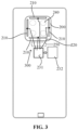
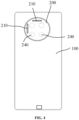
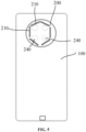
- the cross section of the metal protector 200 may have a generally rectangular shape as shown in FIG. 2 to FIG. 4 , and may also have a circular shape as shown in FIG. 5 .
- the cross section of the metal protector 200 may also have other shapes, which is not limited in the present application.
- the metal protector 200 has a smaller cross-sectional area. There are fewer devices on the metal protector 200, and the forming positions of the slots 210 are more flexible, so that the form of the antenna can be controlled more easily. For example, an antenna capable of transmitting and receiving the circularly polarized signals may be formed. Thus, the antenna is formed on the metal protector 200, so that the polarization mode of the antenna is more flexible, and it is more advantageous in improving the positioning capacity of the antenna.
- the metal protector 200 when applied to a terminal, when the terminal falls or is subjected to a collision, the metal protector 200 will firstly be subjected to an external force to reduce damage to the image acquisition assembly by the external force, thereby ensuring a protection effect on the image acquisition assembly.
- the radiating slots 210 are formed or disposed in the metal protector 200, and the phase shift feed assembly 300 excites the radiating slots in different directions to be capable of transmitting and receiving the wireless signals, so as to realize the antenna function without affecting the protection function of the metal protector 200.
- such a structure can expand the arrangement space of the antenna and increase the number of antennas.
- the same number of antennas is provided, so that the number of antennas formed on the middle frame 100 can be reduced, the influence of the slots 210 on the structural strength of the middle frame 100 is reduced, and the space utilization of the terminal is improved, thereby effectively saving the structural space of the middle frame 100.
- the metal protector of the image acquisition assembly is provided with a plurality of radiating slots, so that transmitting and receiving of wireless signals is realized through the radiating slots.
- the forming direction of the first radiating slot and the forming direction of the second radiating slot are different from each other and are arranged at the first set angle.
- the first radiating slot and the second radiating slot may radiate wireless signals in different polarization directions respectively under the excitation of the phase shift feed assembly 300.
- Such an antenna form improves the controllability of the antenna polarization mode, thereby facilitating achieving the circular polarization of the antenna signals.
- the antennas are formed on the metal protector of the image acquisition assembly, so that the arrangement space of the antenna is enlarged, and the number of antennas formed in the middle frame is reduced, which is beneficial to improve the structural strength of the middle frame and improve the space utilization of the terminal, thereby effectively saving the structural space of the middle frame.
- first direction R1 is perpendicular to the second direction R2, and the second set angle is 90 degrees. This is merely one example of the first direction R1 and the second direction R2.
- the first direction R1 and the second direction R2 are interchangeable, and the angle between the first direction R1 and the second direction R2 may be comprised between 0 degree and 360 degrees.
- the angle between the first radiating slot and the second radiating slot is 90 degrees
- the phase difference between the first signal and the second signal is 90 degrees
- amplitude of the first signal is equal to amplitude of the second signal.
- the polarization mode of the wireless signals radiated by the radiating slots is circular polarization.
- the polarization mode of the wireless signals radiated by the radiating slots is right circular polarization.
- the metal protector includes two radiating slots.
- the metal protector includes at least one first radiating slot and at least one second radiating slot, thus, the metal protector includes at least two radiating slots.
- the metal protector includes a plurality of radiating slots 210, the number of the first radiating slots is equal to the number of the second radiating slots.
- the metal protector includes a plurality of radiating slots 210, two adjacent radiating slots 210 are arranged at an interval. As shown in FIG. 2 to FIG. 5 , the two adjacent radiating slots do not communicate with one another.
- the number of the radiating slots is two.
- the number of the first radiating slot and the number of the second radiating slot are one, and the two radiating slots are arranged perpendicular to each other.
- the two radiating slots are arranged in a T shape.
- an end of one of the radiating slots 210 is arranged adjacent to an end of the other one of the radiating slots 210.
- each of the two radiating slots is arranged along one of the edges of the metal protector 200, and an end of one of the radiating slots is arranged adjacent to an end of the other one of the radiating slots. This arrangement can make full use of the structural space of the metal protector 200, and realize the light transmitting function, the protection function and the antenna function of the metal protector 200 to the image acquisition assembly.
- the two radiating slots 210 are symmetrically distributed on the metal protector 200.
- the first radiating slot 211 and the second radiating slot 212 are located on two adjacent edges of the metal protector 200 respectively.
- the metal protector 200 includes four radiating slots 210.
- the number of the first radiating slots is two, and the number of the second radiating slots is two.
- the four radiating slots 210 are arranged adjacent to one another in end-to-end manner.
- each two adjacent radiating slots 210 are arranged perpendicularly to each other.
- the plurality of radiating slots 210 are distributed in an annular pattern.
- the polarization mode of the wireless signals generated by the plurality of slots 210 distributed in an annular pattern is closer to circular polarization, which is beneficial to further improve the positioning function of the antenna assembly.
- the four slots 210 are distributed in a rectangular annular pattern.
- the metal protector 200 includes six radiating slots 210.
- the six radiating slots are arranged adjacent to one another in end-to-end manner, an angle between each two adjacent radiating slots 210 is 120 degrees, and the second set angle is 60 degrees.
- the angle between each two adjacent radiating slots 210 is 120 degrees.
- the six radiating slots 210 are distributed in an annular pattern.
- the six radiating slots 210 are arranged adjacent to one another in end-to-end manner to form a generally hexagonal annular structure.
- the phase shift feed assembly 300 includes:
- the feed assembly 250 may be coupled with the metal protector 200 to feed the metal protector.
- the feed assembly 250 further includes a feed tab. The feed tab is spaced apart from the metal protector and configured to feed the radiating slots through electromagnetic coupling.
- the feed tab may be a metal sheet, which is located below the slot. That is, the metal sheet is located at an inner side of the metal protector.
- the feed tab may be connected to the processing assembly through a feeder line.
- the feed assembly 250 may be in contact with the metal protector 200 to feed the metal protector.
- the feeder line of the feed assembly 250 is directly in contact with the metal protector to achieve contact feeding.
- the point at which the feeder line is in contact with the metal protector may serve as a feed point.
- an elastic feeder line such as an elastic sheet or an elastic probe may be adopted to connect the metal sheet and the processing assembly, so as to further guarantee the contact between the metal sheet and the metal protector, as well as the performance of the antenna assembly for transmitting and receiving signals.
- the feed assembly 250 includes: a feeder line 220 electrically connected to the processing assembly and electrically connected to the feed point of each radiating slot 210.
- the feed point is located on an outer edge of each radiating slot 210 or an inner edge of each radiating slot 210.
- a distance between the outer edge of each radiating slot and a center of the metal protector 200 is larger than a distance between the inner edge of each radiating slot and the center of the metal protector 200.
- FIG. 2 exemplarily illustrates a feed point located on the outer edge of each radiating slot 210.
- each radiating slot is closer to the center of the metal protector.
- the feeder line 220 includes a coaxial line, a microstrip line, a strip line or a Liquid Crystal Polymer (LCP) line.
- LCP Liquid Crystal Polymer
- one radiating slot 210 includes one feed point.
- the processing assembly 231 may adjust the amplitude and/or phase of the electrical signals transferred to the feed point, so that the first radiating slot 211 radiates the first signal in a first polarization direction, and the second radiating slot 212 radiates the second signal in a second polarization direction.
- the processing assembly 231 may be integrated in a Central Processing Unit (CPU) of the terminal.
- CPU Central Processing Unit
- the feed point is located at a midpoint position of each radiating slot 210.
- the metal sheet of the feed point may be disposed at the midpoint of each radiating slot 210.
- the position of the feed point may also slightly deviate from the midpoint position of each radiating slot.
- the feed point at the midpoint position of each radiating slot is more advantageous in transmitting and receiving the wireless signals.
- the antenna assembly further includes: an insulating filler filled in each slot 210.
- the insulating filler is filled in each slot 210, so that the strength of the metal protector 200 is improved on the basis of ensuring the function of the antenna for transmitting and receiving the wireless signals, which is beneficial to enhance the protection effect on the image acquisition assembly.
- the filler may be made of an insulating material, such as resin or silicate compounds.
- an injection molding material in a molten state may be filled into the slots 210 by injection molding, and then may be cooled and solidified to form an insulating filler.
- the lens of the image acquisition assembly may be aligned with each through hole 240, so as to receive light from an external environment and capture images.
- the metal protector may include one or more through holes 240.
- the through hole 240 is closer to the center of the metal protector 200. That is, the through hole 240 is located within an area enclosed by the slots 210. Such a distribution may simultaneously achieve the protection effect of the metal protector 200 on the image acquisition assembly, the function of the image acquisition assembly for receiving light and the antenna function.
- An example of the present application further provides a terminal.
- the terminal includes:
- the terminal further includes a circuit board disposed on the middle frame 100.
- the antenna assembly is disposed on the circuit board.
- the circuit board may be a main board of the terminal.
- the metal protector 200 may be disposed on the middle frame 100 by means of a snap connection, welding, bonding or a connection through a fastener such as a screw.
- the metal protector 200 and the middle frame 100 are integrally formed by molding.
- the terminals include but not limited to mobile phones, tablets, laptops, unmanned aerial vehicles or wearable devices, etc.
- the terminal is a mobile phone.
- a radiating slot 210 of appropriate length is formed in the metal protector 200 of a mobile phone camera in a transverse direction and a longitudinal direction respectively, namely a first radiating slot 211 formed or disposed in the transverse direction and a second radiating slot 212 formed or disposed in the longitudinal direction.
- the first radiating slot 211 is excited to generate a transverse mode, so as to radiate the horizontally polarized waves.
- the second radiating slot 212 is excited to generate a longitudinal mode, so as to radiate the vertically polarized waves.
- the polarization modes of the electromagnetic waves in the two directions are orthogonal to each other.
- the feed point is connected to the processing assembly through a feeder line 220.
- the processing assembly generates signals having equal amplitude and a phase difference of 90 degrees to excite the first radiating slot 211 and the second exciting slot 212 respectively. That is, a right-hand circularly polarized signal is generated.
- the processing assembly transmits a received signal to a positioning processing unit 232 (generally a CPU) for post processing, so as to decode time information and position information.
- the antenna of the metal protector 200 is an antenna including four radiating slots.
- the processing assembly generates four signals having equal amplitude and a phase difference of 90 degrees to excite the four radiating slots 210 respectively.
- a right-hand circularly polarized signal is generated since the excitation signal has a phase difference of 90 degrees. This form has better circular polarization performance.
- the metal protector 200 of the antenna assembly is electrically connected to the middle frame 100.
- the middle frame 100 forms at least a part of a ground plane of the antenna.
- a part of an area of the metal protector 200 which is not connected to the feed point may serve as the ground plane of the antenna together with the middle frame 100.
- the terminal further includes: a shell disposed on the middle frame 100, in which the shell is provided with an opening, and the antenna assembly is disposed in the opening and at least partially exposed outside the shell.
- the antenna assembly is exposed to the outside, so that the interference of a device in the terminal, such as a circuit board or a loudspeaker, to the antenna is reduced.
- the shell is a battery case.
- the circuit board, the loudspeaker, the battery, the camera and other devices of the terminal may all be located between the middle frame 100 and the shell.
Landscapes
- Engineering & Computer Science (AREA)
- Computer Networks & Wireless Communication (AREA)
- Signal Processing (AREA)
- Variable-Direction Aerials And Aerial Arrays (AREA)
- Details Of Aerials (AREA)
- Waveguide Aerials (AREA)
Claims (13)
- Eine Antennenanordnung, umfassend:einen Metallprotektor (200) einer Bilderfassungsanordnung, wobei der Metallprotektor (200) eine Vielzahl von abstrahlenden Schlitzen (210) umfasst, wobei die Vielzahl von abstrahlenden Schlitzen (210) einen ersten abstrahlenden Schlitz (211), der in einer ersten Richtung (R1) ausgebildet ist, und einen zweiten abstrahlenden Schlitz (212), der in einer zweiten Richtung (R2) ausgebildet ist, umfasst, und die erste Richtung (R1) und die zweite Richtung (R2) in einem ersten Einstellwinkel angeordnet sind; undeine Phasenschiebungs-Zuführeinheit (300), die konfiguriert ist, ein erstes Signal und ein zweites Signal mit einem Phasenunterschied eines zweiten Einstellwinkels zu erzeugen, wobei das erste Signal konfiguriert ist, den ersten abstrahlenden Schlitz (211) anzuregen, und das zweite Signal konfiguriert ist, den zweiten abstrahlenden Schlitz (212) anzuregen,wobei die Phasenschiebungs-Zuführeinheit (300) umfasst:eine Verarbeitungseinheit (231), die konfiguriert ist, das erste Signal und das zweite Signal mit dem Phasenunterschied des zweiten Einstellwinkels zu erzeugen; undeine Zuführeinheit (250), die mit der Verarbeitungseinheit (231) verbunden ist und konfiguriert ist, die abstrahlenden Schlitze (210) zu speisen,dadurch gekennzeichnet, dass die Zuführeinheit (250) umfasst:eine Zuführleitung (220), die elektrisch mit der Verarbeitungseinheit (231) und elektrisch mit einem Zuführungspunkt jedes abstrahlenden Schlitzes (210) verbunden ist,wobei der Zuführungspunkt an einer äußeren Kante jedes abstrahlenden Schlitzes (210) oder an einer inneren Kante jedes abstrahlenden Schlitzes (210) angeordnet ist und wobei der Abstand zwischen der äußeren Kante jedes abstrahlenden Schlitzes (210) und einem Mittelpunkt des Metallprotektors (200) größer ist als der Abstand zwischen der inneren Kante jedes abstrahlenden Schlitzes (210) und dem Mittelpunkt des Metallprotektors (200).
- Die Antennenanordnung nach Anspruch 1, wobei die erste Richtung (R1) senkrecht zur zweiten Richtung (R2) ist und der zweite Einstellwinkel 90 Grad beträgt.
- Die Antennenanordnung nach Anspruch 1 oder Anspruch 2, wobei der Metallprotektor (200) zwei abstrahlende Schlitze (210), den ersten abstrahlenden Schlitz (211) und den zweiten abstrahlenden Schlitz (212) umfasst.
- Die Antennenanordnung nach Anspruch 3, wobei ein Ende des ersten abstrahlenden Schlitzes (211) angrenzend an ein Ende des zweiten abstrahlenden Schlitzes (212) angeordnet ist.
- Die Antennenanordnung nach Anspruch 1 oder Anspruch 2, wobei der Metallprotektor (200) vier abstrahlende Schlitze (210) umfasst.
- Die Antennenanordnung nach Anspruch 5, wobei die vier abstrahlenden Schlitze (210) angrenzend zueinander in einer End-zu-End-Anordnung angeordnet sind.
- Die Antennenanordnung nach Anspruch 1, wobei der Metallprotektor (200) sechs abstrahlende Schlitze (210) umfasst, die sechs abstrahlenden Schlitze (210) angrenzend zueinander in einer End-zu-End-Anordnung angeordnet sind, ein Winkel zwischen jeweils zwei benachbarten abstrahlenden Schlitzen (210) 120 Grad beträgt und der zweite Einstellwinkel 60 Grad beträgt.
- Die Antennenanordnung nach Anspruch 1, Anspruch 2, Anspruch 5, Anspruch 6 oder Anspruch 7, wobei die Vielzahl von abstrahlenden Schlitzen (210) in einem ringförmigen Muster angeordnet sind.
- Die Antennenanordnung nach Anspruch 1, wobei der Zuführungspunkt an einer mittigen Position jedes abstrahlenden Schlitzes (210) angeordnet ist.
- Die Antennenanordnung nach Anspruch 1, wobei die Antennenanordnung ferner umfasst:
eine Zuführlasche, wobei die Zuführlasche vom Metallprotektor (200) beabstandet ist und konfiguriert ist, die abstrahlenden Schlitze (210) durch elektromagnetische Kopplung zu speisen. - Ein Endgerät, dadurch gekennzeichnet, dass das Endgerät umfasst:eine Antennenanordnung nach einem der Ansprüche 1 bis 10; undeinen Mittelrahmen (100), wobei die Phasenschiebungs-Zuführeinheit (300) der Antennenanordnung auf dem Mittelrahmen (100) angeordnet ist.
- Das Endgerät nach Anspruch 11, wobei der Metallprotektor (200) der Antennenanordnung elektrisch mit dem Mittelrahmen (100) verbunden ist und der Mittelrahmen (100) zumindest einen Teil einer Massefläche der Antennenanordnung bildet.
- Das Endgerät nach Anspruch 11 oder Anspruch 12, wobei das Endgerät ferner umfasst:
eine auf dem Mittelrahmen (100) angeordnete Schale, wobei die Schale mit einer Öffnung versehen ist und die Antennenanordnung in der Öffnung angeordnet und zumindest teilweise außerhalb der Schale freiliegend ist.
Applications Claiming Priority (1)
| Application Number | Priority Date | Filing Date | Title |
|---|---|---|---|
| CN202110263719.4A CN115084830B (zh) | 2021-03-11 | 2021-03-11 | 天线模组和终端 |
Publications (2)
| Publication Number | Publication Date |
|---|---|
| EP4057442A1 EP4057442A1 (de) | 2022-09-14 |
| EP4057442B1 true EP4057442B1 (de) | 2025-01-15 |
Family
ID=77042718
Family Applications (1)
| Application Number | Title | Priority Date | Filing Date |
|---|---|---|---|
| EP21187137.1A Active EP4057442B1 (de) | 2021-03-11 | 2021-07-22 | Antennenanordnung und endgerät |
Country Status (3)
| Country | Link |
|---|---|
| US (1) | US11522272B2 (de) |
| EP (1) | EP4057442B1 (de) |
| CN (1) | CN115084830B (de) |
Family Cites Families (13)
| Publication number | Priority date | Publication date | Assignee | Title |
|---|---|---|---|---|
| JP4418375B2 (ja) | 2005-01-25 | 2010-02-17 | アルプス電気株式会社 | アンテナ装置 |
| US9331396B2 (en) * | 2013-05-06 | 2016-05-03 | Qualcomm Incorporated | Antenna structure having orthogonal polarizations |
| KR102508922B1 (ko) | 2016-11-07 | 2023-03-13 | 삼성전자주식회사 | 안테나를 포함하는 전자 장치 |
| CN106898883B (zh) * | 2017-02-28 | 2020-08-04 | 深圳市万普拉斯科技有限公司 | 近场通信nfc天线及移动终端 |
| JP6573182B2 (ja) * | 2018-05-14 | 2019-09-11 | パナソニックIpマネジメント株式会社 | 撮像装置 |
| MX2019012587A (es) * | 2018-10-19 | 2020-07-28 | Abl Ip Holding Llc | Sistemas de antena para comunicacion inalambrica en luminarias. |
| CN113330645B (zh) | 2018-11-09 | 2024-04-09 | 索尼公司 | 天线装置 |
| KR102604289B1 (ko) * | 2018-11-28 | 2023-11-20 | 삼성전자주식회사 | 전자 장치 및 그의 안테나 구조 |
| CN110994134A (zh) * | 2019-12-19 | 2020-04-10 | 深圳市信维通信股份有限公司 | 天线结构及移动终端 |
| CN210805996U (zh) * | 2019-12-31 | 2020-06-19 | Oppo广东移动通信有限公司 | 天线装置及电子设备 |
| CN111342205B (zh) * | 2020-03-03 | 2021-09-21 | 安徽精卓光显技术有限责任公司 | 装饰板及电子设备 |
| CN210899362U (zh) * | 2020-03-12 | 2020-06-30 | 维沃移动通信有限公司 | 摄像头模组及电子设备 |
| CN111697325B (zh) * | 2020-06-23 | 2022-02-15 | Oppo广东移动通信有限公司 | 一种天线模组及终端 |
-
2021
- 2021-03-11 CN CN202110263719.4A patent/CN115084830B/zh active Active
- 2021-07-14 US US17/376,149 patent/US11522272B2/en active Active
- 2021-07-22 EP EP21187137.1A patent/EP4057442B1/de active Active
Also Published As
| Publication number | Publication date |
|---|---|
| CN115084830A (zh) | 2022-09-20 |
| US11522272B2 (en) | 2022-12-06 |
| EP4057442A1 (de) | 2022-09-14 |
| US20220294098A1 (en) | 2022-09-15 |
| CN115084830B (zh) | 2024-05-07 |
Similar Documents
| Publication | Publication Date | Title |
|---|---|---|
| US12413263B2 (en) | Dielectric resonator antenna modules | |
| US8441408B2 (en) | Miniaturized multiple input multiple output (MIMO) antenna | |
| US6879294B2 (en) | Dual antenna capable of transmitting and receiving circularly polarized electromagnetic wave and linearly polarized electromagnetic wave | |
| US7289068B2 (en) | Planar antenna with multiple radiators and notched ground pattern | |
| US7015860B2 (en) | Microstrip Yagi-Uda antenna | |
| CN107808998B (zh) | 多极化辐射振子及天线 | |
| EP3688840B1 (de) | Senkrechte längsstrahlerantennen | |
| US11342661B2 (en) | Antenna structure and wireless communication device using the same | |
| CN103460506B (zh) | 具有圆极化特性的双天线结构 | |
| US6697023B1 (en) | Built-in multi-band mobile phone antenna with meandering conductive portions | |
| EP3091608B1 (de) | Antennensystem und antennenmodul mit einem parasitären element für strahlungsmusterverbesserungen | |
| EP2375488B1 (de) | Planarantenne und tragbare Vorrichtung | |
| US12489220B2 (en) | Terminal antenna | |
| EP4057442B1 (de) | Antennenanordnung und endgerät | |
| JPH1174721A (ja) | 表面実装型円偏波アンテナおよびそれを用いた無線装置 | |
| JP2009284088A (ja) | マイクロストリップアンテナ | |
| CN212626013U (zh) | 一种天线装置和车辆 | |
| JP2004215245A (ja) | 平面アンテナ | |
| US20250167450A1 (en) | Antenna and communication device | |
| JP7444022B2 (ja) | 車両用無線通信装置 | |
| CN119315245A (zh) | 电子设备 | |
| JP2004048367A (ja) | 複合アンテナ | |
| CN119009450A (zh) | 电子设备 | |
| CN119092979A (zh) | 电子设备 | |
| CN119070031A (zh) | 电子设备 |
Legal Events
| Date | Code | Title | Description |
|---|---|---|---|
| PUAI | Public reference made under article 153(3) epc to a published international application that has entered the european phase |
Free format text: ORIGINAL CODE: 0009012 |
|
| STAA | Information on the status of an ep patent application or granted ep patent |
Free format text: STATUS: THE APPLICATION HAS BEEN PUBLISHED |
|
| AK | Designated contracting states |
Kind code of ref document: A1 Designated state(s): AL AT BE BG CH CY CZ DE DK EE ES FI FR GB GR HR HU IE IS IT LI LT LU LV MC MK MT NL NO PL PT RO RS SE SI SK SM TR |
|
| STAA | Information on the status of an ep patent application or granted ep patent |
Free format text: STATUS: REQUEST FOR EXAMINATION WAS MADE |
|
| 17P | Request for examination filed |
Effective date: 20230217 |
|
| RBV | Designated contracting states (corrected) |
Designated state(s): AL AT BE BG CH CY CZ DE DK EE ES FI FR GB GR HR HU IE IS IT LI LT LU LV MC MK MT NL NO PL PT RO RS SE SI SK SM TR |
|
| GRAP | Despatch of communication of intention to grant a patent |
Free format text: ORIGINAL CODE: EPIDOSNIGR1 |
|
| STAA | Information on the status of an ep patent application or granted ep patent |
Free format text: STATUS: GRANT OF PATENT IS INTENDED |
|
| RIC1 | Information provided on ipc code assigned before grant |
Ipc: H01Q 21/24 20060101ALI20240730BHEP Ipc: H01Q 13/10 20060101ALI20240730BHEP Ipc: H01Q 1/44 20060101ALI20240730BHEP Ipc: H01Q 1/24 20060101AFI20240730BHEP |
|
| INTG | Intention to grant announced |
Effective date: 20240904 |
|
| RIN1 | Information on inventor provided before grant (corrected) |
Inventor name: YANG, JINGYU |
|
| GRAS | Grant fee paid |
Free format text: ORIGINAL CODE: EPIDOSNIGR3 |
|
| GRAA | (expected) grant |
Free format text: ORIGINAL CODE: 0009210 |
|
| STAA | Information on the status of an ep patent application or granted ep patent |
Free format text: STATUS: THE PATENT HAS BEEN GRANTED |
|
| P01 | Opt-out of the competence of the unified patent court (upc) registered |
Free format text: CASE NUMBER: APP_64252/2024 Effective date: 20241204 |
|
| AK | Designated contracting states |
Kind code of ref document: B1 Designated state(s): AL AT BE BG CH CY CZ DE DK EE ES FI FR GB GR HR HU IE IS IT LI LT LU LV MC MK MT NL NO PL PT RO RS SE SI SK SM TR |
|
| REG | Reference to a national code |
Ref country code: CH Ref legal event code: EP Ref country code: GB Ref legal event code: FG4D |
|
| REG | Reference to a national code |
Ref country code: DE Ref legal event code: R096 Ref document number: 602021024883 Country of ref document: DE |
|
| REG | Reference to a national code |
Ref country code: IE Ref legal event code: FG4D |
|
| REG | Reference to a national code |
Ref country code: NL Ref legal event code: MP Effective date: 20250115 |
|
| PG25 | Lapsed in a contracting state [announced via postgrant information from national office to epo] |
Ref country code: NL Free format text: LAPSE BECAUSE OF FAILURE TO SUBMIT A TRANSLATION OF THE DESCRIPTION OR TO PAY THE FEE WITHIN THE PRESCRIBED TIME-LIMIT Effective date: 20250115 |
|
| PG25 | Lapsed in a contracting state [announced via postgrant information from national office to epo] |
Ref country code: RS Free format text: LAPSE BECAUSE OF FAILURE TO SUBMIT A TRANSLATION OF THE DESCRIPTION OR TO PAY THE FEE WITHIN THE PRESCRIBED TIME-LIMIT Effective date: 20250415 |
|
| PG25 | Lapsed in a contracting state [announced via postgrant information from national office to epo] |
Ref country code: FI Free format text: LAPSE BECAUSE OF FAILURE TO SUBMIT A TRANSLATION OF THE DESCRIPTION OR TO PAY THE FEE WITHIN THE PRESCRIBED TIME-LIMIT Effective date: 20250115 |
|
| PG25 | Lapsed in a contracting state [announced via postgrant information from national office to epo] |
Ref country code: PL Free format text: LAPSE BECAUSE OF FAILURE TO SUBMIT A TRANSLATION OF THE DESCRIPTION OR TO PAY THE FEE WITHIN THE PRESCRIBED TIME-LIMIT Effective date: 20250115 |
|
| PG25 | Lapsed in a contracting state [announced via postgrant information from national office to epo] |
Ref country code: ES Free format text: LAPSE BECAUSE OF FAILURE TO SUBMIT A TRANSLATION OF THE DESCRIPTION OR TO PAY THE FEE WITHIN THE PRESCRIBED TIME-LIMIT Effective date: 20250115 |
|
| REG | Reference to a national code |
Ref country code: LT Ref legal event code: MG9D |
|
| PG25 | Lapsed in a contracting state [announced via postgrant information from national office to epo] |
Ref country code: IS Free format text: LAPSE BECAUSE OF FAILURE TO SUBMIT A TRANSLATION OF THE DESCRIPTION OR TO PAY THE FEE WITHIN THE PRESCRIBED TIME-LIMIT Effective date: 20250515 Ref country code: NO Free format text: LAPSE BECAUSE OF FAILURE TO SUBMIT A TRANSLATION OF THE DESCRIPTION OR TO PAY THE FEE WITHIN THE PRESCRIBED TIME-LIMIT Effective date: 20250415 |
|
| REG | Reference to a national code |
Ref country code: AT Ref legal event code: MK05 Ref document number: 1760448 Country of ref document: AT Kind code of ref document: T Effective date: 20250115 |
|
| PG25 | Lapsed in a contracting state [announced via postgrant information from national office to epo] |
Ref country code: HR Free format text: LAPSE BECAUSE OF FAILURE TO SUBMIT A TRANSLATION OF THE DESCRIPTION OR TO PAY THE FEE WITHIN THE PRESCRIBED TIME-LIMIT Effective date: 20250115 |
|
| PG25 | Lapsed in a contracting state [announced via postgrant information from national office to epo] |
Ref country code: LV Free format text: LAPSE BECAUSE OF FAILURE TO SUBMIT A TRANSLATION OF THE DESCRIPTION OR TO PAY THE FEE WITHIN THE PRESCRIBED TIME-LIMIT Effective date: 20250115 Ref country code: PT Free format text: LAPSE BECAUSE OF FAILURE TO SUBMIT A TRANSLATION OF THE DESCRIPTION OR TO PAY THE FEE WITHIN THE PRESCRIBED TIME-LIMIT Effective date: 20250515 |
|
| PG25 | Lapsed in a contracting state [announced via postgrant information from national office to epo] |
Ref country code: GR Free format text: LAPSE BECAUSE OF FAILURE TO SUBMIT A TRANSLATION OF THE DESCRIPTION OR TO PAY THE FEE WITHIN THE PRESCRIBED TIME-LIMIT Effective date: 20250416 Ref country code: BG Free format text: LAPSE BECAUSE OF FAILURE TO SUBMIT A TRANSLATION OF THE DESCRIPTION OR TO PAY THE FEE WITHIN THE PRESCRIBED TIME-LIMIT Effective date: 20250115 |
|
| PG25 | Lapsed in a contracting state [announced via postgrant information from national office to epo] |
Ref country code: AT Free format text: LAPSE BECAUSE OF FAILURE TO SUBMIT A TRANSLATION OF THE DESCRIPTION OR TO PAY THE FEE WITHIN THE PRESCRIBED TIME-LIMIT Effective date: 20250115 |
|
| PG25 | Lapsed in a contracting state [announced via postgrant information from national office to epo] |
Ref country code: SE Free format text: LAPSE BECAUSE OF FAILURE TO SUBMIT A TRANSLATION OF THE DESCRIPTION OR TO PAY THE FEE WITHIN THE PRESCRIBED TIME-LIMIT Effective date: 20250115 |
|
| PG25 | Lapsed in a contracting state [announced via postgrant information from national office to epo] |
Ref country code: SM Free format text: LAPSE BECAUSE OF FAILURE TO SUBMIT A TRANSLATION OF THE DESCRIPTION OR TO PAY THE FEE WITHIN THE PRESCRIBED TIME-LIMIT Effective date: 20250115 |
|
| PG25 | Lapsed in a contracting state [announced via postgrant information from national office to epo] |
Ref country code: DK Free format text: LAPSE BECAUSE OF FAILURE TO SUBMIT A TRANSLATION OF THE DESCRIPTION OR TO PAY THE FEE WITHIN THE PRESCRIBED TIME-LIMIT Effective date: 20250115 |
|
| PG25 | Lapsed in a contracting state [announced via postgrant information from national office to epo] |
Ref country code: IT Free format text: LAPSE BECAUSE OF FAILURE TO SUBMIT A TRANSLATION OF THE DESCRIPTION OR TO PAY THE FEE WITHIN THE PRESCRIBED TIME-LIMIT Effective date: 20250115 |
|
| PGFP | Annual fee paid to national office [announced via postgrant information from national office to epo] |
Ref country code: GB Payment date: 20250724 Year of fee payment: 5 |
|
| REG | Reference to a national code |
Ref country code: DE Ref legal event code: R097 Ref document number: 602021024883 Country of ref document: DE |
|
| PG25 | Lapsed in a contracting state [announced via postgrant information from national office to epo] |
Ref country code: CZ Free format text: LAPSE BECAUSE OF FAILURE TO SUBMIT A TRANSLATION OF THE DESCRIPTION OR TO PAY THE FEE WITHIN THE PRESCRIBED TIME-LIMIT Effective date: 20250115 Ref country code: EE Free format text: LAPSE BECAUSE OF FAILURE TO SUBMIT A TRANSLATION OF THE DESCRIPTION OR TO PAY THE FEE WITHIN THE PRESCRIBED TIME-LIMIT Effective date: 20250115 |
|
| PG25 | Lapsed in a contracting state [announced via postgrant information from national office to epo] |
Ref country code: RO Free format text: LAPSE BECAUSE OF FAILURE TO SUBMIT A TRANSLATION OF THE DESCRIPTION OR TO PAY THE FEE WITHIN THE PRESCRIBED TIME-LIMIT Effective date: 20250115 |
|
| PG25 | Lapsed in a contracting state [announced via postgrant information from national office to epo] |
Ref country code: SK Free format text: LAPSE BECAUSE OF FAILURE TO SUBMIT A TRANSLATION OF THE DESCRIPTION OR TO PAY THE FEE WITHIN THE PRESCRIBED TIME-LIMIT Effective date: 20250115 |
|
| PLBE | No opposition filed within time limit |
Free format text: ORIGINAL CODE: 0009261 |
|
| STAA | Information on the status of an ep patent application or granted ep patent |
Free format text: STATUS: NO OPPOSITION FILED WITHIN TIME LIMIT |