EP4056972B1 - Verfahren und vorrichtung zur bestimmung der übergangstemperatur eines leistungshalbleiters - Google Patents
Verfahren und vorrichtung zur bestimmung der übergangstemperatur eines leistungshalbleiters Download PDFInfo
- Publication number
- EP4056972B1 EP4056972B1 EP21305283.0A EP21305283A EP4056972B1 EP 4056972 B1 EP4056972 B1 EP 4056972B1 EP 21305283 A EP21305283 A EP 21305283A EP 4056972 B1 EP4056972 B1 EP 4056972B1
- Authority
- EP
- European Patent Office
- Prior art keywords
- switch
- signal
- terminal
- processor
- opening
- Prior art date
- Legal status (The legal status is an assumption and is not a legal conclusion. Google has not performed a legal analysis and makes no representation as to the accuracy of the status listed.)
- Active
Links
Images


Classifications
-
- G—PHYSICS
- G01—MEASURING; TESTING
- G01K—MEASURING TEMPERATURE; MEASURING QUANTITY OF HEAT; THERMALLY-SENSITIVE ELEMENTS NOT OTHERWISE PROVIDED FOR
- G01K7/00—Measuring temperature based on the use of electric or magnetic elements directly sensitive to heat ; Power supply therefor, e.g. using thermoelectric elements
- G01K7/01—Measuring temperature based on the use of electric or magnetic elements directly sensitive to heat ; Power supply therefor, e.g. using thermoelectric elements using semiconducting elements having PN junctions
-
- G—PHYSICS
- G01—MEASURING; TESTING
- G01K—MEASURING TEMPERATURE; MEASURING QUANTITY OF HEAT; THERMALLY-SENSITIVE ELEMENTS NOT OTHERWISE PROVIDED FOR
- G01K7/00—Measuring temperature based on the use of electric or magnetic elements directly sensitive to heat ; Power supply therefor, e.g. using thermoelectric elements
- G01K7/16—Measuring temperature based on the use of electric or magnetic elements directly sensitive to heat ; Power supply therefor, e.g. using thermoelectric elements using resistive elements
- G01K7/22—Measuring temperature based on the use of electric or magnetic elements directly sensitive to heat ; Power supply therefor, e.g. using thermoelectric elements using resistive elements the element being a non-linear resistance, e.g. thermistor
- G01K7/24—Measuring temperature based on the use of electric or magnetic elements directly sensitive to heat ; Power supply therefor, e.g. using thermoelectric elements using resistive elements the element being a non-linear resistance, e.g. thermistor in a specially-adapted circuit, e.g. bridge circuit
-
- G—PHYSICS
- G01—MEASURING; TESTING
- G01K—MEASURING TEMPERATURE; MEASURING QUANTITY OF HEAT; THERMALLY-SENSITIVE ELEMENTS NOT OTHERWISE PROVIDED FOR
- G01K2215/00—Details concerning sensor power supply
-
- G—PHYSICS
- G01—MEASURING; TESTING
- G01K—MEASURING TEMPERATURE; MEASURING QUANTITY OF HEAT; THERMALLY-SENSITIVE ELEMENTS NOT OTHERWISE PROVIDED FOR
- G01K2217/00—Temperature measurement using electric or magnetic components already present in the system to be measured
Definitions
- the present invention relates generally to a method and a device for determining the junction temperature of a power semiconductor.
- junction temperature of a power semiconductor is a critical parameter to be measured during the operation of the power converter to increase the robustness against over-heating and monitor the state of health of a power module.
- the classical solutions have a small sensitivity in regards to the temperature requiring precise excitations, voltage/current sources and should be acquired precisely in time given their dynamic characteristics.
- Some of the Temperature Sensitive Electrical Parameters (TSEP) based methods also need external sensors for compensating the TSEP dependency on the load conditions.
- TSEP Temperature Sensitive Electrical Parameters
- Some TSEP parameters cannot be measured independently during the power semiconductor operation. Given the variation of some TSEP with the load conditions, a complex calibration phase is necessary.
- the patent application US2016/131538 discloses a temperature detection device. More specifically, the temperature of a power transistor is measured by using a diode formed in the vicinity of the transistor.
- the present invention aims to provide a method and a device for determining the junction temperature of a power semiconductor that does not need high time resolution or high resolution current and voltage measurement and no accurate signal source for determing the function temperature of the power seminconductor.
- the present invention concerns a method for determining the junction temperature of a power semiconductor using a temperature sensitive electrical parameter of a thermal sensitive electrical device as defined in claim 1.
- the present invention concerns also a system for determining the junction temperature of a power semiconductor as defined in claim 8.
- Fig. 1 represents a device for determining the junction temperature of a power semiconductor from a temperature sensitive parameter according to the invention.
- the device for determining the junction temperature of a power semiconductor from a temperature sensitive parameter comprises a thermal sensitive electrical device 100, a signal source 120, an external electrical circuit 110, a compensation module 130, a measurement module 140 and a calculation module 150.
- the signal source 120 is a DC or AC current or voltage source, for example a 25mA dc current source or a 2V peak to peak sinusoidal voltage source.
- the external electrical circuit 110 is a voltage source in series with a resistor or a short circuit or a resistor or a capacitor or an inductor or a switch.
- the thermal sensitive electrical device 100 is for example an internal gate resistance in series with an input capacitance of the power semiconductor device, or a PN junction or a thermistor, resistance dependent on the temperature, implanted on a power semiconductor device, or a PN junction or a thermistor, resistance dependent on the temperature, implanted close to a power semiconductor device.
- the thermal sensitive electrical device 100 will be disclosed in more detail in reference to Figs. 4a to 4c .
- the compensation module 130 is able to connect or disconnect the signal source 120 from the thermal sensitive electrical device 100 in order to enable the measurement module 140 to measure the characteristics of the signal source 120 by measuring a voltage, V i , which is stored on the calculation module 150.
- the compensation module 130 is also able to connect the signal source to the external electrical circuit 110 in order to enable the measurement module 140 to measure the characteristics of the external electrical circuit 110 by measuring a voltage, V j , which is stored on the calculation module 150.
- the compensation module 130 is also able to connect the signal source 120 to the measurement module 140 in order to measure the characteristics of the signal source 120 by measuring a voltage, V k , which is stored on the calculation module 150.
- the measurement module 140 measures the output voltage of the compensation module 130.
- the measurement module 140 is composed by an analogue to digital converter ADC driven by a differential operational amplifier in combination or not with a sample and hold device.
- the calculation module determines the temperature sensitive parameter value from the voltages outputted by the measurement module 140.
- a first terminal of the external electrical circuit 110 is connected to a first terminal of the signal source 120 and to an input noted 4 of the compensation module 130.
- a second terminal of the external electrical circuit 110 is denoted 5.
- the second terminal of the external electric circuit 110 may be connected to a gate of a power semiconductor or to a base of a power semiconductor that is used as thermal sensitive electrical device 100 and to an input noted 2 of the compensation module 130.
- a second terminal of the signal source 120 is connected to an input noted 3 of the compensation module 130.
- a first terminal of the thermal sensitive electrical device 100 is connected to an input noted 2 of the compensation module 130 and a second terminal of the thermal sensitive electrical device 100 is connected to an input noted 1 of the compensation module 130.
- Fig. 2 represents a compensation module of the device for determining the junction temperature of a power semiconductor from a temperature sensitive parameter according to the invention.
- the compensation module 130 is composed of at most six switches S 1 to S 6 .
- the drain of the switch S 1 is connected to the input noted 1 of the compensation module 130.
- the source of the switch S 1 is connected to the source of the switch S 2 , to the source of the switch S 6 , to the drain of the switch S 3 , to a first terminal of a resistor R 1 and to a first terminal of a capacitor C 2 .
- a first terminal of a capacitor C 1 is connected to the input noted 2 of the compensation module 130.
- a second terminal of the capacitor C 1 is connected to the drain of the switch S 2 .
- the drain of the switch S 6 is connected to the input noted 3 of the compensation module 130.
- the input noted 4 of the compensation module 130 is connected to the source of the switch S 3 , to the source of the switch S 4 and to the source of the switch S 5 .
- the voltage Vout at the output of the compensation module 130 is between the source of the switch S 1 and the input noted 4 of the compensation module 130.
- the switch S 6 is used only when the signal source 120 is a voltage source. When the signal source 120 is a current source, the switch S 6 remains closed or may be replaced by a short circuit.
- the compensation module 130 may comprise:
- the compensation module 130 may comprise:
- the compensation module 130 may comprise:
- capacitors C 1 and C 2 are the class 1 type regarding to standard IEC/EN 60384-1.
- the resistor R1 is a stable resistor with a temperature coefficient around 20ppm/°C.
- a classical reference is the resistor family PTN commercialised by the company Vishay.
- Fig. 3 represents an architecture of a calculation module of the device for determining the junction temperature of a power semiconductor from a temperature sensitive parameter according to the invention.
- the calculation module 150 has, for example, an architecture based on components connected together by a bus 301 and a processor 300 controlled by a program as disclosed in Figs. 5a to 5q .
- the bus 301 links the processor 300 to a read only memory ROM 302, a random access memory RAM 303 and an input output I/O IF interface 305.
- the input output I/O IF interface 305 enables the calculation module to drive the switches S 1 and/or S 2 and/or S 3 and/or S 4 and/or S 5 and/or S 6 and to receive the signal Vm outputted by the measurement module 140.
- the memory 303 contains registers intended to receive variables and the instructions of the program related to the algorithm as disclosed in Figs. 5a to 5q .
- the read-only memory or possibly a Flash memory 302 contains instructions of the programs related to the algorithm as disclosed in Figs. 5a to 5q , when the calculation module 150 is powered on, are loaded to the random access memory 303.
- the program may also be executed directly from the ROM memory 302.
- the calculation performed by the calculation module 150 may be implemented in software by execution of a set of instructions or program by a programmable computing machine, such as a PC ( Personal Computer ), a DSP ( Digital Signal Processor ) or a microcontroller; or else implemented in hardware by a machine or a dedicated component, such as an FPGA ( Field-Programmable Gate Array ) or an ASIC (Application-Specific Integrated Circuit).
- a programmable computing machine such as a PC ( Personal Computer ), a DSP ( Digital Signal Processor ) or a microcontroller; or else implemented in hardware by a machine or a dedicated component, such as an FPGA ( Field-Programmable Gate Array ) or an ASIC (Application-Specific Integrated Circuit).
- the calculation module 150 includes circuitry, or a device including circuitry, causing the calculation module 150 to perform the program related to the algorithm as disclosed in Figs. 5a to 5q .
- Fig. 4a represents a first embodiment of a temperature sensitive electric device used for determining the junction temperature of a power semiconductor according to the invention.
- the thermal sensitive electrical device 100 is a power semiconductor device.
- the emitter of the power semiconductor device is connected to the input noted 1 of the compensation module 130 and the gate of the power semiconductor device is connected to the input noted 2 of the compensation module 130 and to the terminal 5 of the external electric circuit 110.
- the thermal sensitive parameter is proportional to the internal gate resistance value that is in series with the input capacitance of the power semiconductor.
- the power semiconductor device may be a MOS-type transistor, for example a MOSFET or an IGBT, the source or the emitter of the power semiconductor device is connected to the input noted 1 of the compensation module 130 and the gate of the power semiconductor device is connected to the input noted 2 of the compensation module 130 and to the terminal 5 of the external electric circuit 110.
- MOS-type transistor for example a MOSFET or an IGBT
- Fig. 4b represents a second embodiment of a temperature sensitive electric device used for determining the junction temperature of a power semiconductor according to the invention.
- the thermal sensitive electrical device 100 is a PN junction implanted on a power semiconductor device or implanted close to the power semiconductor device.
- the thermal sensitive parameter is proportional to the voltage across the PN junction.
- the cathode of the PN junction is connected to the input noted 4 of the compensation module 130, the gate of the power semiconductor device is connected to the terminal 5 of the external electric circuit 110 and the anode of the PN junction is connected to the input noted 1 of the compensation module 130.
- the source or the emitter of the power semiconductor device is connected to the input noted 4 of the compensation module 130.
- the gate of the power semiconductor device is also connected to the input noted 2 of the compensation module 130 and to the terminal 5 of the external electric.
- Fig. 4c represents a third embodiment of a temperature sensitive electric device used for determining the junction temperature of a power semiconductor according to the invention.
- the thermal sensitive electrical device 100 is a resistance dependent on the temperature, implanted on the power semiconductor device or implanted close to a power semiconductor.
- the thermal sensitive parameter is proportional to the resistance value.
- a first terminal of the resistance is connected to the input noted 4 of the compensation module 130, the gate of the power semiconductor device is connected to the terminal 5 of the external electric circuit 110 and a second terminal of the resistance is connected to the input noted 1 of the compensation module 130.
- the source or the emitter of the power semiconductor device is connected to the input noted 4 of the compensation module 130.
- the gate of the power semiconductor device is connected to the input noted 2 of the compensation module 130 and to the terminal 5 of the external electric.
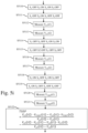
- Fig. 5a represents an example of an algorithm for determining the junction temperature of a power semiconductor from a temperature sensitive parameter according to the present invention and when the compensation module comprises only the switches S 1 and S 3 .
- the present algorithm is disclosed in an example wherein it is executed by the processor 300.
- the processor 300 transfers a signal for closing the switch S 1 and a signal for closing the switch S 3 .
- the processor 300 reads the signal V o outputted by the measurement module 140.
- the Signal V o is representative of an offset voltage generated by parasitic resistors of the compensation module 130 and by an internal offset of the measurement module 140.
- V o is superior to 0.3 Volts, it means that the measurement module 140 has a drift and that a possible malfunctioning exists on the compensation module 130 and/or on the measurement module 140.
- the processor 300 transfers a signal for closing the switch S 1 and a signal for opening the switch S 3 .
- the signal source 120 provides a current with an amplitude I1 that flows through the thermal sensitive electrical device 100.
- the processor 300 At an instant t1, reads the signal V TSEP (t1) outputted by the measurement module 140.
- the instant t1 is for example triggered 1 ⁇ s after the opening of the switch S 3 .
- the processor 300 At step S5004, the processor 300, at an instant t2, reads the signal V TSEP (t2) outputted by the measurement module 140.
- the instant t2 is for example triggered 2 ⁇ s after the opening of the switch S 3 .
- the processor 300 determines the temperature using a look up table determined during a calibration phase strored in the RAM memory 303.
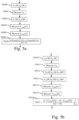
- Fig. 5b represents an example of an algorithm for determining the junction temperature of a power semiconductor from a temperature sensitive parameter according to the present invention and when the compensation module comprises only the switches S 1 , S 3 and S 4 and the resistor R 1 .
- the present algorithm is disclosed in an example wherein it is executed by the processor 300.
- the processor 300 transfers a signal for opening the switch S 3 and a signal for closing the switch S 4 .
- the signal source 120 provides a current with an amplitude I1 that flows through the resistor R1.
- the processor 300 reads the signal V R1 outputted by the measurement module 140 after a certain time, for example 1 ⁇ s.
- the Signal V R1 is representative of the current of the signal source 120 and the resistor R 1 of the compensation module 130.
- the signal V R1 may be outputted for monitoring purposes.
- V R1 increases by more than 5% compared to the nominal value, for example 100mV, the signal source 120 has drift and a possible malfunctioning is present on the signal source 120.
- the processor 300 transfers a signal for closing the switch S 1 , a signal for closing the switch S 3 and a signal for opening the switch S 4 .
- the processor 300 transfers a signal for closing the switch S 1 , a signal for opening the switch S 3 and a signal for opening the switch S 4 .
- the processor 300 reads the signal V TSEP (t1) outputted by the measurement module 140.
- the instant t1 is for example triggered 1 ⁇ s after the opening of the switch S 3 .
- the processor 300 reads the signal V TSEP (t2) outputted by the measurement module 140.
- the instant t2 is for example triggered 2 ⁇ s after the opening of the switch S 3 .
- the processor 300 determines the temperature using a look up table determined during a calibration phase strored in the RAM memory 303.
- Fig. 5c represents an example of an algorithm for determining the junction temperature of a power semiconductor from a temperature sensitive parameter according to the present invention and when the compensation module comprises only switches S 2 , S 3 and S 1 and the capacitor C 1.
- the present algorithm is disclosed in an example wherein it is executed by the processor 300.
- the processor 300 transfers a signal for opening the switch S 1 , a signal for closing the switch S 2 and a signal for closing the switch S 3 .
- the capacitor C1 is charged at the voltage of the external circuit 110.
- the processor 300 transfers a signal for opening the switch S 1 , a signal for closing the switch S 2 and a signal for opening the switch S 3 .
- the processor 300 At an instant t1, reads the signal V C1 (t1) outputted by the measurement module 140.
- the instant t1 is for example triggered 1 ⁇ s after the opening of the switch S 3 .
- the signal source 120 provides a current with an amplitude I1 that flows through the capacitor C1 and to the external electrical circuit 110.
- the processor 300 reads the signal V C1 (t2) outputted by the measurement module 140.
- the instant t2 is for example triggered 2 ⁇ s after the opening of the switch S 3 .
- the signal V C1 (t1), V C1 (t2) may be used for monitoring purposes.
- the nominal value of t 2 ⁇ V C 1 t 1 ⁇ t 1 ⁇ V C 1 t 2 t 2 ⁇ t 1 is memorized or calculated.
- the processor 300 transfers a signal for closing the switch S 1 , a signal for opening the switch S 2 and a signal for closing the switch S 3 .
- the processor 300 transfers a signal for closing the switch S 1 , a signal for opening the switch S 2 and a signal for opening the switch S 3 .
- the signal source 120 provides a current with an amplitude I1 that flows through the thermal sensitive electrical device 100.
- the processor 300 At an instant t1, reads the signal V TSEP (t1) outputted by the measurement module 140.
- the instant t1 is for example triggered 1 ⁇ s after the opening of the switch S 3 .
- the processor 300 reads the signal V TSEP (t2) outputted by the measurement module 140.
- the instant t2 is for example triggered 2 ⁇ s after the opening of the switch S 3 .
- the processor 300 determines the temperature using a look up table determined during a calibration phase strored in the RAM memory 303.
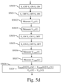
- Fig. 5d represents an example of an algorithm for determining the junction temperature of a power semiconductor from a temperature sensitive parameter according to the present invention and when the compensation module comprises only the switches S 1 , S 3 and S 5 and the capacitor C 2.
- the present algorithm is disclosed in an example wherein it is executed by the processor 300.
- the processor 300 transfers a signal for opening the switch S 1 , a signal for closing the switch S 3 and a signal for closing the switch S 5 .
- the processor 300 transfers a signal for opening the switch S 1 , a signal for opening the switch S 3 and a signal for closing the switch S 5 .
- the processor 300 At step S5032, the processor 300, at an instant t1, reads the signal V C2 (t1) outputted by the measurement module 140.
- the instant t1 is for example triggered 1 ⁇ s after the opening of the switch S 3 .
- the processor 300 reads the signal V C2 (t2) outputted by the measurement module 140.
- the instant t2 is for example triggered 2 ⁇ s after the opening of the switch S 3 .
- the signals V C2 (t1), V C2 (t2) may be outputted for monitoring purposes.
- the nominal value of V C2 (t1) is memorized or calculated.
- V C2 (t1) increases or reduces by more than 10% compared to the nominalvalue, for example 1.8V or 2.2V, a malfunctioning is present on the switch S 3 .
- the processor 300 transfers a signal for closing the switch S 1 , a signal for closing the switch S 3 and a signal for opening the switch S 5 .
- the processor 300 transfers a signal for closing the switch S 1 , a signal for opening the switch S 3 and a signal for opening the switch S 3 .
- the processor 300 At an instant t1, reads the signal V TSEP (t1) outputted by the measurement module 140.
- the instant t1 is for example triggered 1 ⁇ s after the opening of the switch S 3 .
- the processor 300 reads the signal V TSEP (t2) outputted by the measurement module 140.
- the instant t2 is for example triggered 2 ⁇ s after the opening of the switch S 3 .
- the processor 300 determines the temperature using a look up table determined during a calibration phase strored in the RAM memory 303.
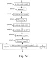
- Fig. 5e represents an example of an algorithm for determining the junction temperature of a power semiconductor from a temperature sensitive parameter according to the first embodiment and when the compensation module comprises only the switches S 3 , S 4 and S 1 and the resistor R 1 .
- the present algorithm is disclosed in an example wherein it is executed by the processor 300.
- the processor 300 transfers a signal for closing the switch S 1 , a signal for closing the switch S 3 and a signal for opening the switch S 4 .
- the processor 300 reads the signal V o outputted by the measurement module 140.
- the Signal V o is representative of an offset voltage generated by parasitic resistors of the compensation module 130 and by an internal offset of the measurement module 140.
- V o is superior to 0.3 Volts, it means that the measurement module 140 has a drift and that a possible malfunctioning exists on the compensation module 130 and/or on the measurement module 140.
- the processor 300 transfers a signal for closing the switch S 1 , a signal for opening the switch S 3 and a signal for closing the switch S 4 .
- the signal source 120 provides a current with an amplitude I1 that flows through the resistor R1. In the steady state, the current I1 flows entirely through R1.
- the processor 300 reads the signal V R1 outputted by the measurement module 140.
- the Signal V R1 is representative of the current of the signal source 120 and the resistor R 1 of the compensation module 130.
- the signal V R1 may be outputted for monitoring purposes.
- V R1 increases by more than 5% compared to the nominal value, for example 100mV, the signal source 120 has drift and a possible malfunctioning is present on the signal source 120.
- the processor 300 transfers a signal for closing the switch S 1 , a signal for closing the switch S 3 and a signal for opening the switch S 4 .
- the processor 300 transfers a signal for closing the switch S 1 , a signal for opening the switch S 3 and a signal for opening the switch S 4 .
- the processor 300 At an instant t1, reads the signal V TSEP (t1) outputted by the measurement module 140.
- the instant t1 is for example triggered 1 ⁇ s after the opening of the switch S 3 .
- the processor 300 reads the signal V TSEP (t2) outputted by the measurement module 140.
- the instant t2 is for example triggered 2 ⁇ s after the opening of the switch S 3 .
- the processor 300 determines the temperature using a look up table determined during a calibration phase strored in the RAM memory 303.
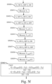
- Fig. 5f represents an example of an algorithm for determining the junction temperature of a power semiconductor from a temperature sensitive parameter according to the first embodiment and when the compensation module comprises only the switches S 1 , S 2 and S 3 and the capacitor C 1.
- the present algorithm is disclosed in an example wherein it is executed by the processor 300.
- the processor 300 transfers a signal for closing the switch S 1 , a signal for opening the switch S 2 and a signal for closing the switch S 3 .
- the processor 300 reads the signal V o outputted by the measurement module 140.
- the Signal V o is representative of an offset voltage generated by parasitic resistors of the compensation module 130 and by an internal offset of the measurement module 140.
- V o is superior to 0.3 Volts, it means that the measurement module 140 has a drift and that a possible malfunctioning exists on the compensation module 130 and/or on the measurement module 140.
- the processor 300 transfers a signal for opening the switch S 1 , a signal for closing the switch S 2 and a signal for closing the switch S 3 .
- the processor 300 transfers a signal for opening the switch S 1 , a signal for closing the switch S 2 and a signal for opening the switch S 3 .
- the processor 300 At an instant t1, reads the signal V C1 (t1) outputted by the measurement module 140.
- the instant t1 is for example triggered 1 ⁇ s after the opening of the switch S 3 .
- the processor 300 At step S5055, the processor 300, at an instant t2, reads the signal V C1 (t2) outputted by the measurement module 140.
- the instant t2 is for example triggered 2 ⁇ s after the opening of the switch S 3 .
- the signal V C1 (t1), V C1 (t2) may be used for monitoring purposes.
- the nominal value of t 2 ⁇ V C 1 t 1 ⁇ t 1 ⁇ V C 1 t 2 t 2 ⁇ t 1 is memorized or calculated.
- the processor 300 transfers a signal for closing the switch S 1 , a signal for opening the switch S 2 and a signal for closing the switch S 3 .
- the processor 300 transfers a signal for closing the switch S 1 , a signal for opening the switch S 2 and a signal for opening the switch S 3 .
- the processor 300 reads the signal V TSEP (t1) outputted by the measurement module 140.
- the instant t1 is for example triggered 1 ⁇ s after the opening of the switch S 3 .
- the processor 300 reads the signal V TSEP (t2) outputted by the measurement module 140.
- the instant t2 is for example triggered 2 ⁇ s after the opening of the switch S 3 .
- the processor 300 determines the temperature using a look up table determined during a calibration phase strored in the RAM memory 303.
- Fig. 5g represents an example of an algorithm for determining the junction temperature of a power semiconductor from a temperature sensitive parameter according to the first embodiment and when the compensation module comprises only the switches S 1 , S 3 and S 5 and the capacitor C 2 .
- the present algorithm is disclosed in an example wherein it is executed by the processor 300.
- the processor 300 transfers a signal for closing the switch S 1 , a signal for closing the switch S 3 and a signal for opening the switch S 5 .
- the processor 300 reads the signal V o outputted by the measurement module 140.
- the Signal V o is representative of an offset voltage generated by parasitic resistors of the compensation module 130 and by an internal offset of the measurement module 140.
- V o is superior to 0.3 Volts, it means that the measurement module 140 has a drift and that a possible malfunctioning exists on the compensation module 130 and/or on the measurement module 140.
- the processor 300 transfers a signal for closing the switch S 1 , a signal for closing the switch S 3 and a signal for closing the switch S 5 .
- the processor 300 transfers a signal for opening the switch S 1 , a signal for opening the switch S 3 and a signal for closing the switch S 5 .
- the processor 300 At an instant t1, reads the signal V C2 (t1) outputted by the measurement module 140.
- the instant t1 is for example triggered 1 ⁇ s after the opening of the switch S 3 .
- the processor 300 reads the signal V C2 (t2) outputted by the measurement module 140.
- the instant t2 is for example triggered 2 ⁇ s after the opening of the switch S 3 .
- the signals V C2 (t1), V C2 (t2) may be outputted for monitoring purposes.
- the nominal value of V C2 (t1) is memorized or calculated.
- V C2 (t1) increases or reduces by more than 10% compared to the nominalvalue, for example 1.8V or 2.2V, a malfunctioning is present on the switch S 3 .
- the processor 300 transfers a signal for closing the switch S 1 , a signal for closing the switch S 3 and a signal for opening the switch S 5 .
- the processor 300 transfers a signal for closing the switch S 1 , a signal for opening the switch S 3 and a signal for opening the switch S 5 .
- the processor 300 At an instant t1, reads the signal V TSEP (t1) outputted by the measurement module 140.
- the instant t1 is for example triggered 1 ⁇ s after the opening of the switch S 3 .
- the processor 300 reads the signal V TSEP (t2) outputted by the measurement module 140.
- the instant t2 is for example triggered 2 ⁇ s after the opening of the switch S 3 .
- the processor 300 determines the temperature using a look up table determined during a calibration phase strored in the RAM memory 303.
- Fig. 5h represents an example of an algorithm for determining the junction temperature of a power semiconductor from a temperature sensitive parameter according to the first embodiment and when the compensation module comprises only the switches S 1 , S 3 , S 4 and S 5 and the capacitor C 2 .
- the present algorithm is disclosed in an example wherein it is executed by the processor 300.
- the processor 300 transfers a signal for closing the switch S 1 , a signal for closing the switch S 3 , a signal for closing the switch S 4 and a signal for opening the switch S 5 .
- the processor 300 reads the signal V R1 outputted by the measurement module 140.
- the Signal V R1 is representative of the current of the signal source 120 and the resistor R 1 of the compensation module 130.
- the signal V R1 may be outputted for monitoring purposes.
- V R1 increases by more than 5% compared to the nominal value, for example 100mV, the signal source 120 has a drift and a possible malfunctioning is present on the signal source 120.
- the processor 300 transfers a signal for opening the switch S 1 , a signal for closing the switch S 3 , a signal for opening the switch S 4 and a signal for opening the switch S 5 .
- the processor 300 transfers a signal for opening the switch S 1 , a signal for opening the switch S 3 , a signal for opening the switch S 4 and a signal for opening the switch S 5 .
- the processor 300 At an instant t1, reads the signal V C2 (t1) outputted by the measurement module 140.
- the instant t1 is for example triggered 1 ⁇ s after the opening of the switch S 3 .
- the processor 300 At step S5095, the processor 300, at an instant t2, reads the signal V C2 (t2) outputted by the measurement module 140.
- the instant t2 is for example triggered 2 ⁇ s after the opening of the switch S 3 .
- the signals V C2 (t1), V C2 (t2) may be outputted for monitoring purposes.
- the nominal value of V C2 (t1) is memorized or calculated.
- V C2 (t1) increases or reduces by more than 10% compared to the nominalvalue, for example 1.8V or 2.2V, a malfunctioning is present on the switch S 3 .
- the processor 300 transfers a signal for closing the switch S 1 , a signal for closing the switch S 3 , a signal for opening the switch S 4 and a signal for opening the switch S 5 .
- the processor 300 transfers a signal for closing the switch S 1 , a signal for opening the switch S 3 , a signal for opening the switch S 4 and a signal for opening the switch S 5 .
- the processor 300 At an instant t1, reads the signal V TSEP (t1) outputted by the measurement module 140.
- the instant t1 is for example triggered 1 ⁇ s after the opening of the switch S 3 .
- the processor 300 reads the signal V TSEP (t2) outputted by the measurement module 140.
- the instant t2 is for example triggered 2 ⁇ s after the opening of the switch S 3 .
- the processor 300 determines the temperature using a look up table determined during a calibration phase strored in the RAM memory 303.
- Fig. 5i represents an example of an algorithm for determining the junction temperature of a power semiconductor from a temperature sensitive parameter according to the first embodiment and when the compensation module comprises only only the switches S 1 , S 2 , S 3 and S 5 and the capacitors C 1 and C 2 .
- the present algorithm is disclosed in an example wherein it is executed by the processor 300.
- the processor 300 transfers a signal for opening the switch S 1 , a signal for closing the switch S 2 , a signal for closing the switch S 3 and a signal for opening the switch S 5 .
- the processor 300 transfers a signal for opening the switch S 1 , a signal for closing the switch S 2 , a signal for opening the switch S 3 and a signal for opening the switch S 5 .
- the processor 300 At an instant t1, reads the signal V C1 (t1) outputted by the measurement module 140.
- the instant t1 is for example triggered 1 ⁇ s after the opening of the switch S 3 .
- the processor 300 reads the signal V C1 (t2) outputted by the measurement module 140.
- the instant t2 is for example triggered 2 ⁇ s after the opening of the switch S 3 .
- the signal V C1 (t1), V C1 (t2) may be used for monitoring purposes.
- the nominal value of t 2 ⁇ V C 1 t 1 ⁇ t 1 ⁇ V C 1 t 2 t 2 ⁇ t 1 is memorized or calculated.
- the processor 300 transfers a signal for opening the switch S 1 , a signal for opening the switch S 2 , a signal for closing the switch S 3 and a signal for closing the switch S 5 .
- the processor 300 transfers a signal for opening the switch S 1 , a signal for opening the switch S 2 , a signal for opening the switch S 4 and a signal for closing the switch S 5 .
- the processor 300 reads the signal V C2 (t1) outputted by the measurement module 140.
- the instant t1 is for example triggered 1 ⁇ s after the opening of the switch S 3 .
- the processor 300 reads the signal V C2 (t2) outputted by the measurement module 140.
- the instant t2 is for example triggered 1 ⁇ s after the opening of the switch S 3 .
- the signals V C2 (t1), V C2 (t2) may be outputted for monitoring purposes.
- the nominal value of V C2 (t1) is memorized or calculated.
- V C2 (t1) increases or reduces by more than 10% compared to the nominalvalue, for example 1.8V or 2.2V, a malfunctioning is present on the switch S 3 .
- the processor 300 transfers a signal for closing the switch S 1 , a signal for opening the switch S 2 , a signal for closing the switch S 3 and a signal for opening the switch S 5 .
- the processor 300 transfers a signal for closing the switch S 1 , a signal for opening the switch S 2 , a signal for opening the switch S 3 and a signal for opening the switch S 5 .
- the processor 300 At step S5120, the processor 300, at an instant t1, reads the signal V TSEP (t1) outputted by the measurement module 140.
- the instant t1 is for example triggered 1 ⁇ s after the opening of the switch S 3 .
- the processor 300 At an instant t2, reads the signal V TSEP (t2) outputted by the measurement module 140.
- the instant t2 is for example triggered 1 ⁇ s after the opening of the switch S 3 .
- the processor 300 determines the temperature using a look up table determined during a calibration phase strored in the RAM memory 303.
- Fig. 5j represents an example of an algorithm for determining the junction temperature of a power semiconductor from a temperature sensitive parameter according to the first embodiment and when the compensation module comprises only only the switches S 1 , S 3 , S 4 and S 5 and the capacitor C 2 and the resistor R 1 .
- the present algorithm is disclosed in an example wherein it is executed by the processor 300.
- the processor 300 transfers a signal for closing the switch S 1 , a signal for closing the switch S 3 , a signal for opening the switch S 4 and a signal for opening the switch S 5 .
- the processor 300 reads the signal V o outputted by the measurement module 140.
- the signal V o is representative of an offset voltage generated by parasitic resistors of the compensation module 130 and by an internal offset of the measurement module 140.
- V o is superior to 0.3 Volts, it means that the measurement module 140 has a drift and a possible malfunctioning exists on the compensation module 130 and/or on the measurement module 140.
- the processor 300 transfers a signal for closing the switch S 1 , a signal for opening the switch S 3 , a signal for closing the switch S 4 and a signal for opening the switch S 5 .
- the processor 300 reads the signal V R1 outputted by the measurement module 140.
- the Signal V R1 is representative of the current of the signal source 120 and the resistor R 1 of the compensation module 130.
- the signal V R1 may be outputted for monitoring purposes.
- V R1 increases by more than 5% compared to the nominal value, for example 100mV, the signal source 120 has drift and a possible malfunctioning is present on the signal source 120.
- the processor 300 transfers a signal for opening the switch S 1 , a signal for closing the switch S 3 , a signal for opening the switch S 4 and a signal for closing the switch S 5 .
- the processor 300 transfers a signal for opening the switch S 1 , a signal for opening the switch S 3 , a signal for opening the switch S 4 and a signal for closing the switch S 5 .
- the processor 300 reads the signal V C2 (t1) outputted by the measurement module 140.
- the instant t1 is for example triggered 1 ⁇ s after the opening of the switch S 3 .
- the processor 300 reads the signal V C2 (t2) outputted by the measurement module 140.
- the instant t2 is for example triggered 2 ⁇ s after the opening of the switch S 3 .
- the signals V C2 (t1), V C2 (t2) may be outputted for monitoring purposes.
- the nominal value of V C2 (t1) is memorized or calculated.
- V C2 (t1) increases or reduces by more than 10% compared to the nominalvalue, for example 1.8V or 2.2V, a malfunctioning is present on the switch S 3 .
- the processor 300 transfers a signal for closing the switch S 1 , a signal for opening the switch S 3 , a signal for opening the switch S 4 and a signal for opening the switch S 5 .
- the processor 300 transfers a signal for closing the switch S 1 , a signal for opening the switch S 3 , a signal for opening the switch S 4 and a signal for opening the switch S 5 .
- the processor 300 At step S5141, the processor 300, at an instant t1, reads the signal V TSEP (t1) outputted by the measurement module 140.
- the instant t1 is for example triggered 1 ⁇ s after the opening of the switch S 3 .
- the processor 300 reads the signal V TSEP (t2) outputted by the measurement module 140.
- the instant t2 is for example triggered 2 ⁇ s after the opening of the switch S 3 .
- the processor 300 determines the temperature using a look up table determined during a calibration phase strored in the RAM memory 303.
- Fig. 5k represents an example of an algorithm for determining the junction temperature of a power semiconductor from a temperature sensitive parameter according to the first embodiment and when the compensation module comprises the switches S 1 , S 2 , S 3 , S 4 and S 5 and the capacitors C 1 , C 2 and the resistor R 1 .
- the present algorithm is disclosed in an example wherein it is executed by the processor 300.
- the processor 300 transfers a signal for closing the switch S 1 , a signal for opening the switch S 2 , a signal for opening the switch S 3 , a signal for closing the switch S 4 and a signal for opening the switch S 5 .
- the processor 300 reads the signal V R1 outputted by the measurement module 140.
- the Signal V R1 is representative of the current of the signal source 120 and the resistor R 1 of the compensation module 130.
- the signal V R1 may be outputted for monitoring purposes.
- V R1 increases by more than 5% compared to the nominal value, for example 100mV, the signal source 120 has drift and a possible malfunctioning is present on the signal source 120.
- the processor 300 transfers a signal for opening the switch S 1 , a signal for closing the switch S 2 , a signal for closing the switch S 3 , a signal for opening the switch S 4 and a signal for opening the switch S 5 .
- the processor 300 transfers a signal for opening the switch S 1 , a signal for closing the switch S 2 , a signal for opening the switch S 3 , a signal for opening the switch S 4 and a signal for opening the switch S 5 .
- the processor 300 At an instant t1, reads the signal V C1 (t1) outputted by the measurement module 140.
- the instant t1 is for example triggered 1 ⁇ s after the opening of the switch S 3 .
- the processor 300 reads the signal V C1 (t2) outputted by the measurement module 140.
- the instant t2 is for example triggered 2 ⁇ s after the opening of the switch S 3 .
- the signal V C1 (t1), V C1 (t2) may be used for monitoring purposes.
- the nominal value of t 2 ⁇ V C 1 t 1 ⁇ t 1 ⁇ V C 1 t 2 t 2 ⁇ t 1 is memorized or calculated.
- the processor 300 transfers a signal for opening the switch S 1 , a signal for opening the switch S 2 , a signal for closing the switch S 3 , a signal for opening the switch S 4 and a signal for closing the switch S 5 .
- the processor 300 transfers a signal for opening the switch S 1 , a signal for opening the switch S 2 , a signal for opening the switch S 3 , a signal for opening the switch S 4 and a signal for closing the switch S 5 .
- the processor 300 reads the signal V C2 (t1) outputted by the measurement module 140.
- the instant t1 is for example triggered 1 ⁇ s after the opening of the switch S 3 .
- the processor 300 reads the signal V C2 (t2) outputted by the measurement module 140.
- the instant t2 is for example triggered 2 ⁇ s after the opening of the switch S 3 .
- the signals V C2 (t1), V C2 (t2) may be outputted for monitoring purposes.
- the nominal value of V C2 (t1) is memorized or calculated.
- V C2 (t1) increases or reduces by more than 10% compared to the nominalvalue, for example 1.8V or 2.2V, a malfunctioning is present on the switch S 3 .
- the processor 300 transfers a signal for closing the switch S 1 , a signal for opening the switch S 2 , a signal for closing the switch S 3 , a signal for opening the switch S 4 and a signal for opening the switch S 5 .
- the processor 300 transfers a signal for closing the switch S 1 , a signal for opening the switch S 2 , a signal for opening the switch S 3 , a signal for opening the switch S 4 and a signal for opening the switch S 5 .
- the processor 300 reads the signal V TSEP (t1) outputted by the measurement module 140.
- the instant t1 is for example triggered 1 ⁇ s after the opening of the switch S 3 .
- the processor 300 reads the signal V TSEP (t2) outputted by the measurement module 140.
- the instant t2 is for example triggered 2 ⁇ s after the opening of the switch S 3 .
- the processor 300 determines the temperature using a look up table determined during a calibration phase strored in the RAM memory 303.
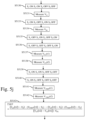
- Fig. 5l represents an example of an algorithm for determining the junction temperature of a power semiconductor from a temperature sensitive parameter according to the first embodiment and when the compensation module comprises the switches S 1 , S 2 , S 3 , S 4 and S 5 and the capacitors C 1 , C 2 and the resistor R 1 .
- the present algorithm is disclosed in an example wherein it is executed by the processor 300.
- the processor 300 transfers a signal for closing the switch S 1 , a signal for opening the switch S 2 , a signal for closing the switch S 3 , a signal for opening the switch S 4 and a signal for opening the switch S 5 .
- the processor 300 transfers a signal for opening the switch S 1 , a signal for opening the switch S 2 , a signal for closing the switch S 3 , a signal for opening the switch S 4 and a signal for opening the switch S 5 .
- the processor 300 reads the signal V o outputted by the measurement module 140.
- the signal V o is representative of an offset voltage generated by parasitic resistors of the compensation module 130 and by an internal offset of the measurement module 140.
- V o is superior to 0.3 Volts, it means that the measurement module 140 has a drift and that a possible malfunctioning exists on the compensation module 130 and/or on the measurement module 140.
- the processor 300 transfers a signal for closing the switch S 1 , a signal for opening the switch S 2 , a signal for opening the switch S 3 , a signal for closing the switch S 4 and a signal for opening the switch S 5 .
- the signal source 120 provides a current with an amplitude I1 that flows through the resistor R1.
- the processor 300 transfers a signal for opening the switch S 1 , a signal for opening the switch S 2 , a signal for opening the switch S 3 , a signal for closing the switch S 4 and a signal for opening the switch S 5 .
- the signal source 120 provides a current with an amplitude I1 that flows through the resistor R1 and through the thermal sensitive electrical device 100 during the transient and flows only through the resistor R1 in the steady state.
- the processor 300 reads the signal V R1 outputted by the measurement module 140 after a certain time, for example 1 ⁇ s.
- the Signal V R1 is representative of the current of the signal source 120 and the resistor R 1 of the compensation module 130.
- the signal V R1 may be outputted for monitoring purposes.
- V R1 increases by more than 5% compared to the nominal value, for example 100mV, the signal source 120 has a drift and a possible malfunctioning is present on the signal source 120.
- the processor 300 transfers a signal for opening the switch S 1 , a signal for closing the switch S 2 , a signal for closing the switch S 3 , a signal for opening the switch S 4 and a signal for opening the switch S 5 .
- the processor 300 transfers a signal for opening the switch S 1 , a signal for closing the switch S 2 , a signal for opening the switch S 3 , a signal for opening the switch S 4 and a signal for opening the switch S 5 .
- the signal source 120 provides a current with an amplitude I1 that flows through the capacitor C1.
- the processor 300 reads the signal V C1 (t1) outputted by the measurement module 140.
- the instant t1 is for example triggered 1 ⁇ s after the opening of the switch S 3 .
- the processor 300 reads the signal V C1 (t2) outputted by the measurement module 140.
- the instant t2 is for example triggered 2 ⁇ s after the opening of the switch S 3 .
- the signal V C1 (t1), V C1 (t2) may be used for monitoring purposes.
- the nominal value of t 2 ⁇ V C 1 t 1 ⁇ t 1 ⁇ V C 1 t 2 t 2 ⁇ t 1 is memorized or calculated.
- the processor 300 transfers a signal for opening the switch S 1 , a signal for opening the switch S 2 , a signal for closing the switch S 3 , a signal for opening the switch S 4 and a signal for closing the switch S 5 .
- the processor 300 transfers a signal for opening the switch S 1 , a signal for opening the switch S 2 , a signal for opening the switch S 3 , a signal for opening the switch S 4 and a signal for closing the switch S 5 .
- the signal source 120 provides a current with an amplitude I1 that flows through the capacitor C2.
- the processor 300 reads the signal V C2 (t1) outputted by the measurement module 140.
- the instant t1 is for example triggered 1 ⁇ s after the opening of the switch S 3 .
- the processor 300 reads the signal V C2 (t2) outputted by the measurement module 140.
- the instant t2 is for example triggered 2 ⁇ s after the opening of the switch S 3 .
- the signals V C2 (t1), V C2 (t2) may be outputted for monitoring purposes.
- the nominal value of V C2 (t1) is memorized or calculated.
- V C2 (t1) increases or reduces by more than 10% compared to the nominalvalue, for example 1.8V or 2.2V, a malfunctioning is present on the switch S 3 .
- the processor 300 transfers a signal for closing the switch S 1 , a signal for opening the switch S 2 , a signal for closing the switch S 3 , a signal for opening the switch S 4 and a signal for opening the switch S 5 .
- the processor 300 transfers a signal for closing the switch S 1 , a signal for opening the switch S 2 , a signal for opening the switch S 3 , a signal for opening the switch S 4 and a signal for opening the switch S 5 .
- the signal source 120 provides a current with an amplitude I1 that flows through the thermal sensitive electrical device 100.
- the processor 300 At an instant t1, reads the signal V TSEP (t1) outputted by the measurement module 140.
- the instant t1 is for example triggered 1 ⁇ s after the opening of the switch S 3 .
- the processor 300 reads the signal V TSEP (t2) outputted by the measurement module 140.
- the instant t2 is for example triggered 2 ⁇ s after the opening of the switch S 3 .
- the processor 300 determines the temperature using a look up table determined during a calibration phase strored in the RAM memory 303.
- Fig. 5m represents an example of an algorithm for determining the junction temperature of a power semiconductor from a temperature sensitive parameter according to the second and third embodiments and when the compensation module comprises only the switches S 1 and S 3 .
- the present algorithm is disclosed in an example wherein it is executed by the processor 300.
- the processor 300 transfers a signal for opening the switch S 1 and a signal for closing the switch S 3 .
- the processor 300 reads the signal V o outputted by the measurement module 140.
- the Signal V o is representative of an offset voltage generated by parasitic resistors of the compensation module 130 and by an internal offset of the measurement module 140.
- V o is superior to 0.3 Volts, it means that the measurement module 140 has a drift and that a possible malfunctioning exists on the compensation module 130 and/or on the measurement module 140.
- the processor 300 transfers a signal for closing the switch S 1 and a signal for opening the switch S 3 .
- the processor 300 At an instant t1, reads the signal V TSEP (t1) outputted by the measurement module 140.
- the instant t1 is for example triggered 1 ⁇ s after the opening of the switch S 3 .
- the processor 300 determines the temperature using a look up table determined during a calibration phase strored in the RAM memory 303.
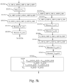
- Fig. 5n represents an example of an algorithm for determining the junction temperature of a power semiconductor from a temperature sensitive parameter according to the second and third embodiments and when the compensation module comprises only the switches S 1 , S 3 and S 4 and the resistor R 1 .
- the present algorithm is disclosed in an example wherein it is executed by the processor 300.
- the processor 300 reads the signal V o outputted by the measurement module 140.
- the Signal V o is representative of an offset voltage generated by parasitic resistors of the compensation module 130 and by an internal offset of the measurement module 140.
- V o is superior to 0.3 Volts, it means that the measurement module 140 has a drift and that a possible malfunctioning exists on the compensation module 130 and/or on the measurement module 140.
- the processor 300 transfers a signal for opening the switch S 1 , a signal for opening the switch S 3 and a signal for closing the switch S 4 .
- the signal source 120 provides a current with an amplitude I1 that flows through the resistor R1. In the steady state, the current I1 flows entirely through R1.
- the processor 300 reads the signal V R1 outputted by the measurement module 140.
- the Signal V R1 is representative of the current of the signal source 120 and the resistor R 1 of the compensation module 130.
- the signal V R1 may be outputted for monitoring purposes.
- V R1 increases by more than 5% compared to the nominal value, for example 100mV, the signal source 120 has a drift and a possible malfunctioning is present on the signal source 120.
- the processor 300 transfers a signal for closing the switch S 1 , a signal for opening the switch S 3 and a signal for opening the switch S 4 .
- the processor 300 At an instant t1, reads the signal V TSEP (t1) outputted by the measurement module 140.
- the instant t1 is for example triggered 1 ⁇ s after the closing of the switch S 1 .
- the processor 300 determines the temperature using a look up table determined during a calibration phase strored in the RAM memory 303.
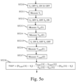
- Fig. 5o represents an example of an algorithm for determining the junction temperature of a power semiconductor from a temperature sensitive parameter according to the second embodiment and when the compensation module comprises only the switches S 1 , S 3 and S 4 and the resistor R 1.
- the present algorithm is disclosed in an example wherein it is executed by the processor 300.
- the processor 300 transfers a signal for opening the switch S 1 , a signal for closing the switch S 3 and a signal for opening the switch S 4 .
- the processor 300 reads the signal V o outputted by the measurement module 140.
- the Signal V o is representative of an offset voltage generated by parasitic resistors of the compensation module 130 and by an internal offset of the measurement module 140.
- V o is superior to 0.3 Volts, it means that the measurement module 140 has a drift and that a possible malfunctioning exists on the compensation module 130 and/or on the measurement module 140.
- the processor 300 transfers a signal for opening the switch S 1 , a signal for opening the switch S 3 and a signal for closing the switch S 4 .
- the processor 300 reads the signal V R1 (II) outputted by the measurement module 140 when the signal source 120 provides a first current I1.
- the signal V R1 (11) is representative of voltage on the resistor R 1 of the compensation module 130.
- the processor 300 reads the signal V R1 (I2) outputted by the measurement module 140 when the signal source provides a second current I2.
- the signal V R1 (I2) is representative of voltage on the resistor R 1 of the compensation module 130.
- the signal V R1 may be outputted for monitoring purposes.
- the nominal value of V R1 is determined by the resistor R 1 value, e.g 100 ⁇ and by the current I1 or I2 value of the signal source 120.
- V R1 increases by more than 5% compared to the nominal value, the signal source 120 has a drift and a possible malfunctioning is present on the signal source 120.
- the processor 300 transfers a signal for closing the switch S 1 , a signal for closing the switch S 3 and a signal for opening the switch S 4 .
- the processor 300 reads the signal V TSEP (I1) outputted by the measurement module 140 when the signal source provides the first current I1.
- the processor 300 reads the signal V TSEP (I2) outputted by the measurement module 140 when the signal source provides the second current I2.
- the processor 300 determines the temperature using a look up table determined during a calibration phase strored in the RAM memory 303.
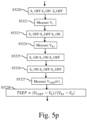
- Fig. 5p represents an example of an algorithm for determining the junction temperature of a power semiconductor from a temperature sensitive parameter according to the second and third embodiments and when the compensation module comprises only the switches S 1 and S 4 and the resistor R 1 .
- the present algorithm is disclosed in an example wherein it is executed by the processor 300.
- the processor 300 transfers a signal for opening the switch S 1 , a signal for closing the switch S 3 and a signal for opening the switch S 4 .
- the processor 300 reads the signal V o outputted by the measurement module 140.
- the Signal V o is representative of an offset voltage generated by parasitic resistors of the compensation module 130 and by an internal offset of the measurement module 140.
- V o is superior to 0.3 Volts, it means that the measurement module 140 has a drift and that a possible malfunctioning exists on the compensation module 130 and/or on the measurement module 140.
- the processor 300 transfers a signal for opening the switch S 1 , a signal for opening the switch S 3 and a signal for closing the switch S 4 .
- the processor 300 reads the signal V R1 outputted by the measurement module 140.
- the Signal V R1 is representative of the current of the signal source 120 and the resistor R 1 of the compensation module 130.
- the signal V R1 may be outputted for monitoring purposes.
- V R1 increases by more than 5% compared to the nominal value, for example 100mV, the signal source 120 has a drift and a possible malfunctioning is present on the signal source 120.
- the processor 300 transfers a signal for closing the switch S 1 , a signal for closing the switch S 3 and a signal for opening the switch S 4 .
- the processor 300 transfers a signal for closing the switch S 1 , a signal for opening the switch S 3 and a signal for opening the switch S 4 .
- the processor 300 At an instant t1, reads the signal V TSEP (t1) outputted by the measurement module 140.
- the instant t1 is for example triggered 1 ⁇ s after the opening of the switch S 3 .
- the processor 300 determines the temperature using a look up table determined during a calibration phase strored in the RAM memory 303.
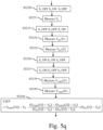
- Fig. 5q represents an example of an algorithm for determining the junction temperature of a power semiconductor from a temperature sensitive parameter according to the second embodiment and when the compensation module comprises only the switches S 1 , S3 and S 4 and the resistor R 1 .
- the present algorithm is disclosed in an example wherein it is executed by the processor 300.
- the processor 300 transfers a signal for opening the switch S 1 , a signal for closing the switch S 3 and a signal for opening the switch S 4 .
- the processor 300 reads the signal V o outputted by the measurement module 140.
- the Signal V o is representative of an offset voltage generated by parasitic resistors of the compensation module 130 and by an internal offset of the measurement module 140.
- V o is superior to 0.3 Volts, it means that the measurement module 140 has a drift and that a possible malfunctioning exists on the compensation module 130 and/or on the measurement module 140.
- the processor 300 transfers a signal for opening the switch S 1 , a signal for opening the switch S 3 and a signal for closing the switch S 4 .
- the processor 300 reads the signal V R1 (I1) outputted by the measurement module 140 when the signal source provides a first current I1.
- the signal V R1 (I1) is representative of voltage on the resistor R 1 of the compensation module 130.
- the processor 300 reads the signal V R1 (I2) outputted by the measurement module 140 when the signal source provides a second current I2.
- the signal V R1 (I2) is representative of voltage on the resistor R 1 of the compensation module 130.
- the signal V R1 may be outputted for monitoring purposes.
- the nominal value of V R1 is determined by the resistor R 1 value and by the current value I1, I2 of the signal source 120.
- V R1 increases by more than 5% compared to the nominal value, the signal source 120 has a drift and a possible malfunctioning is present on the signal source 120.
- the processor 300 transfers a signal for closing the switch S 1 , a signal for closing the switch S 3 and a signal for opening the switch S 4 .
- the processor 300 transfers a signal for closing the switch S 1 , a signal for opening the switch S 3 and a signal for opening the switch S 4 .
- the processor 300 reads the signal V TSEP (I1) outputted by the measurement module 140 when the signal source provides the first current I1.
- the processor 300 reads the signal V TSEP (I2) outputted by the measurement module 140 when the signal source provides the second current I2.
- the processor 300 determines the temperature using a look up table determined during a calibration phase strored in the RAM memory 303.
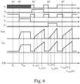
- Fig. 6 represents chronograms of signal used for determining the junction temperature of a power semiconductor according to the first embodiment and wherein all the components shown in Fig. 2 are utilized and that corresponds to the algorithm as disclosed in Fig. 5I .
Landscapes
- Physics & Mathematics (AREA)
- General Physics & Mathematics (AREA)
- Nonlinear Science (AREA)
- Semiconductor Integrated Circuits (AREA)
- Measuring Temperature Or Quantity Of Heat (AREA)
- Testing Of Individual Semiconductor Devices (AREA)
Claims (8)
- Verfahren zur Bestimmung der Sperrschichttemperatur eines Leistungshalbleiters unter Verwendung eines temperatursensitiven elektrischen Parameters eines thermisch empfindlichen elektrischen Bauelements (100) in einem System, welches das thermisch empfindliche elektrische Bauelement (100), eine externe elektrische Schaltung (110), ein Kompensationsmodul (130) und ein Messmodul (140) umfasst, wobei sich das Kompensationsmodul mindestens aus einem ersten und einem zweiten Schalter zusammensetzt, wobei das Verfahren dadurch gekennzeichnet ist, dass ein erster Anschluss des ersten Schalters (S1) mit einem ersten Anschluss des thermisch empfindlichen elektrischen Bauelements verbunden ist, ein zweiter Anschluss des ersten Schalters (S1) mit einem ersten Anschluss des zweiten Schalters (S3), mit einem ersten Anschluss der Signalquelle (120) und mit einem ersten Ausgang des Kompensationsmoduls (130) verbunden ist, ein zweiter Anschluss des zweiten Schalters (S3) mit einem zweiten Anschluss einer Signalquelle und mit einem zweiten Ausgang des Kompensationsmoduls (130) verbunden ist, wobei das Verfahren folgende Schritte umfasst:- Versetzen des ersten Schalters in einen Schließzustand und Versetzen des zweiten Schalters in einen Öffnungszustand während einer ersten Zeitspanne, zur Messung eines ersten Satzes von Spannungen (VTSEP(t1), VTSEP(t2)),- Ändern des Schaltzustands des ersten Schalters und/oder des Schaltzustands des zweiten Schalters oder des Schaltzustands mindestens eines weiteren Schalters während mindestens einer weiteren Zeitspanne, zur Messung mindestens einer weiteren Spannung,- Bestimmen eines Wertes des temperatursensitiven Parameters anhand der gemessenen Spannungen, und wobei:- der Zustand des zweiten Schalters während der als zweite Zeitspanne bezeichneten mindestens einen weiteren Zeitspanne geändert wird, zur Messung der mindestens einen weiteren Spannung, und es sich bei der mindestens einen weiteren Spannung um eine Spannung (Vo) handelt, die eine Offset-Spannung darstellt, welche durch parasitäre Widerstände des Kompensationsmoduls (130) und durch einen internen Offset des Messmoduls (140) erzeugt wird, oder- der Zustand des ersten und des zweiten Schalters während der als dritte Zeitspanne bezeichneten mindestens einen weiteren Zeitspanne geändert wird, und der mindestens eine weitere Schalter ein dritter Schalter (S2) ist, dessen Zustand auf den Schließzustand eingestellt ist, die mindestens eine weitere Spannung ein zweiter Satz von Spannungen (VC1(t1),VC1(t2)) ist, die für die Signalquelle und die externe elektrische Schaltung repräsentativ sind, und ein erster Anschluss des dritten Schalters (S2) mit dem zweiten Anschluss des ersten Schalters verbunden ist, ein zweiter Anschluss des dritten Schalters (S2) mit einem ersten Anschluss eines ersten Kondensators (C1) verbunden ist und ein zweiter Anschluss des ersten Kondensators (C1) mit einem zweiten Anschluss des thermisch empfindlichen elektrischen Bauelements und mit einem zweiten Anschluss der externen elektrischen Schaltung verbunden ist, oder- der Zustand des ersten Schalters während der als vierte Zeitspanne bezeichneten mindestens einen weiteren Zeitspanne geändert wird, und es sich bei dem mindestens einen weiteren Schalter um einen vierten Schalter (S5) handelt, dessen Zustand auf den Schließzustand eingestellt ist, die mindestens eine weitere Spannung ein Satz von Spannungen (VC2(t1), VC2(t2)) ist, die für die Funktion des zweiten Schalters repräsentativ sind, und ein erster Anschluss des vierten Schalters (S5) mit dem zweiten Anschluss des zweiten Schalters verbunden ist, ein zweiter Anschluss des vierten Schalters (S5) mit einem ersten Anschluss eines zweiten Kondensators (C2) verbunden ist und ein zweiter Anschluss des zweiten Kondensators (C2) mit dem zweiten Anschluss des zweiten Schalters (S3) verbunden ist oder es sich bei dem mindestens einen weiteren Schalter um einen fünften Schalter (S4) handelt, dessen Zustand während der als fünfte Zeitspanne bezeichneten mindestens einen weiteren Zeitspanne in den Schließzustand versetzt wird, es sich bei der mindestens einen weiteren Spannung um eine Spannung (VR1) handelt, die für die Signalquelle repräsentativ ist, und ein erster Anschluss des fünften Schalters (S4) mit dem zweiten Anschluss des ersten Schalters verbunden ist, ein zweiter Anschluss des fünften Schalters (S5) mit einem ersten Anschluss eines Widerstands (R1) verbunden ist und ein zweiter Anschluss des Widerstands (R1) mit dem zweiten Anschluss des zweiten Schalters (S3) verbunden ist.
- Verfahren nach Anspruch 1, dadurch gekennzeichnet, dass es sich bei dem thermisch empfindlichen elektrischen Bauelement um einen internen Gate-Widerstand handelt, der mit einer Eingangskapazität eines Leistungshalbleiter-Bauelements in Reihe geschaltet ist.
- Verfahren nach Anspruch 2, dadurch gekennzeichnet, dass es sich bei der externen Schaltung um eine mit einem Widerstand oder einem Kurzschluss oder einem Widerstand oder einem Kondensator oder einem Induktor oder einem Schalter in Reihe geschaltete Spannungsquelle handelt.
- Verfahren nach einem der Ansprüche 1 bis 3, dadurch gekennzeichnet, dass es sich bei der Signalquelle um eine Stromquelle handelt.
- Verfahren nach Anspruch 1 und nach Anspruch 4, dadurch gekennzeichnet, dass es sich bei dem thermisch empfindlichen elektrischen Bauelement um einen auf einem Leistungshalbleiter-Bauelement oder in der Nähe des Leistungshalbleiter-Bauelements implantierten pn-Übergang handelt.
- Verfahren nach Anspruch 1, dadurch gekennzeichnet, dass es sich bei dem thermisch empfindlichen elektrischen Bauelement um einen Widerstand handelt, der von der auf dem Leistungshalbleiter-Bauelement oder in der Nähe eines Leistungshalbleiters implantierten Temperatur abhängig ist.
- Verfahren nach Anspruch 1, dadurch gekennzeichnet, dass die mindestens eine weitere Spannung mit einer Referenzspannung verglichen wird und eine Meldung erzeugt wird, wenn die mindestens eine weitere Spannung außerhalb des Bereichs der Referenzspannung liegt.
- System zur Bestimmung der Sperrschichttemperatur eines Leistungshalbleiters unter Verwendung eines temperatursensitiven elektrischen Parameters eines thermisch empfindlichen elektrischen Bauelements (100), wobei das System das thermisch empfindliche elektrische Bauelement (100), eine externe elektrische Schaltung (110), ein Kompensationsmodul (130), eine Signalquelle (120) und ein Messmodul (140) umfasst, wobei sich das Kompensationsmodul mindestens aus einem ersten und einem zweiten Schalter zusammensetzt, wobei das System dadurch gekennzeichnet ist, dass ein erster Anschluss des ersten Schalters (S1) mit einem ersten Anschluss des thermisch empfindlichen elektrischen Bauelements verbunden ist, ein zweiter Anschluss des ersten Schalters (S1) mit einem ersten Anschluss des zweiten Schalters (S3), mit einem ersten Anschluss der Signalquelle (120) und mit einem ersten Ausgang (3) des Kompensationsmoduls (130) verbunden ist, ein zweiter Anschluss des zweiten Schalters (S3) mit einem zweiten Anschluss der Signalquelle und mit einem zweiten Ausgang (4) des Kompensationsmoduls (130) verbunden ist, wobei das System folgendes umfasst:- Mittel zum Versetzen des ersten Schalters in einen Schließzustand und zum Versetzen des zweiten Schalters in einen Öffnungszustand während einer ersten Zeitspanne, zur Messung eines ersten Satzes von Spannungen (VTSEP(t1), VTSEP(t2)),- Mittel zum Ändern des Zustands des ersten Schalters und/oder des Zustands des zweiten Schalters oder des Zustands mindestens eines weiteren Schalters während mindestens einer weiteren Zeitspanne, zur Messung mindestens einer weiteren Spannung,- Mittel zum Bestimmen eines Wertes des temperatursensitiven Parameters anhand der gemessenen Spannungen, und wobei- der Zustand des zweiten Schalters während der als zweite Zeitspanne bezeichneten mindestens einen weiteren Zeitspanne geändert wird, zur Messung der mindestens einen weiteren Spannung, und es sich bei der mindestens einen weiteren Spannung um eine Spannung (Vo) handelt, die eine Offset-Spannung darstellt, welche durch parasitäre Widerstände des Kompensationsmoduls (130) und durch einen internen Offset des Messmoduls (140) erzeugt wird, oder- der Zustand des ersten und des zweiten Schalters während der als dritte Zeitspanne bezeichneten mindestens einen weiteren Zeitspanne geändert wird, und das System den mindestens einen weiteren Schalter umfasst, bei dem es sich um einen dritten Schalter (S2) handelt, dessen Zustand auf den Schließzustand eingestellt ist, die mindestens eine weitere Spannung ein zweiter Satz von Spannungen (VC1(t1),VC1(t2)) ist, die für die Signalquelle und die externe elektrische Schaltung repräsentativ sind, und ein erster Anschluss des dritten Schalters (S2) mit dem zweiten Anschluss des ersten Schalters verbunden ist, ein zweiter Anschluss des dritten Schalters (S2) mit einem ersten Anschluss eines ersten Kondensators (C1) verbunden ist und ein zweiter Anschluss des ersten Kondensators (C1) mit einem zweiten Anschluss des thermisch empfindlichen elektrischen Bauelements und mit einem zweiten Anschluss der externen elektrischen Schaltung verbunden ist, oder- der Zustand des ersten Schalters während der als vierte Zeitspanne bezeichneten mindestens einen weiteren Zeitspanne geändert wird, und das System umfasstden mindestens einen weiteren Schalter, bei dem es sich um einen vierten Schalter (S5) handelt, dessen Zustand auf den Schließzustand eingestellt ist, die mindestens eine weitere Spannung ein Satz von Spannungen (VC2(t1), VC2(t2)) ist, die für die Funktion des zweiten Schalters repräsentativ sind, und ein erster Anschluss des vierten Schalters (S5) mit dem zweiten Anschluss des zweiten Schalters verbunden ist, ein zweiter Anschluss des vierten Schalters (S5) mit einem ersten Anschluss eines zweiten Kondensators (C2) verbunden ist und ein zweiter Anschluss des zweiten Kondensators (C2) mit dem zweiten Anschluss des zweiten Schalters (S3) verbunden ist, oder das System umfasstden mindestens einen weiteren Schalter, bei dem es sich um einen fünften Schalter (S4) handelt, dessen Zustand während der als fünfte Zeitspanne bezeichneten mindestens einen weiteren Zeitspanne in den Schließzustand versetzt wird, die mindestens eine weitere Spannung eine Spannung (VR1) ist, die für die Signalquelle repräsentativ ist, und ein erster Anschluss des fünften Schalters (S4) mit dem zweiten Anschluss des ersten Schalters verbunden ist, ein zweiter Anschluss des fünften Schalters (S5) mit einem ersten Anschluss eines Widerstands (R1) verbunden ist und ein zweiter Anschluss des Widerstands (R1) mit dem zweiten Anschluss des zweiten Schalters (S3) verbunden ist.
Priority Applications (5)
| Application Number | Priority Date | Filing Date | Title |
|---|---|---|---|
| EP21305283.0A EP4056972B1 (de) | 2021-03-09 | 2021-03-09 | Verfahren und vorrichtung zur bestimmung der übergangstemperatur eines leistungshalbleiters |
| CN202180095187.6A CN116940817A (zh) | 2021-03-09 | 2021-09-14 | 用于确定功率半导体的结温的方法和系统 |
| US18/276,800 US12480823B2 (en) | 2021-03-09 | 2021-09-14 | Method and system for determining junction temperature of power semiconductor |
| JP2023555876A JP2023551344A (ja) | 2021-03-09 | 2021-09-14 | パワー半導体の接合温度を決定する方法及びシステム |
| PCT/JP2021/034921 WO2022190436A1 (en) | 2021-03-09 | 2021-09-14 | Method and system for determining junction temperature of power semiconductor |
Applications Claiming Priority (1)
| Application Number | Priority Date | Filing Date | Title |
|---|---|---|---|
| EP21305283.0A EP4056972B1 (de) | 2021-03-09 | 2021-03-09 | Verfahren und vorrichtung zur bestimmung der übergangstemperatur eines leistungshalbleiters |
Publications (2)
| Publication Number | Publication Date |
|---|---|
| EP4056972A1 EP4056972A1 (de) | 2022-09-14 |
| EP4056972B1 true EP4056972B1 (de) | 2025-05-07 |
Family
ID=75302449
Family Applications (1)
| Application Number | Title | Priority Date | Filing Date |
|---|---|---|---|
| EP21305283.0A Active EP4056972B1 (de) | 2021-03-09 | 2021-03-09 | Verfahren und vorrichtung zur bestimmung der übergangstemperatur eines leistungshalbleiters |
Country Status (5)
| Country | Link |
|---|---|
| US (1) | US12480823B2 (de) |
| EP (1) | EP4056972B1 (de) |
| JP (1) | JP2023551344A (de) |
| CN (1) | CN116940817A (de) |
| WO (1) | WO2022190436A1 (de) |
Families Citing this family (2)
| Publication number | Priority date | Publication date | Assignee | Title |
|---|---|---|---|---|
| CN116184146A (zh) * | 2022-11-23 | 2023-05-30 | 华北电力大学 | 碳化硅mosfet结温在线测量方法、系统及其应用 |
| CN118275850B (zh) * | 2024-06-03 | 2024-08-27 | 安徽大学 | 消除负载干扰的功率半导体器件结温监测模型建立方法 |
Family Cites Families (20)
| Publication number | Priority date | Publication date | Assignee | Title |
|---|---|---|---|---|
| EP0108408B1 (de) * | 1980-04-28 | 1987-07-01 | Fujitsu Limited | Generatorschaltung einer Temperaturkompensationsspannung |
| AT397311B (de) * | 1991-08-16 | 1994-03-25 | Hans Dr Leopold | Verfahren zur bestimmung einer messgrösse sowie schaltungsanordnung zur durchführung des verfahrens |
| BE1008808A3 (nl) * | 1994-10-19 | 1996-08-06 | Imec Inter Uni Micro Electr | Inrichting en werkwijze voor het evalueren van de thermische weerstand van een halfgeleider-component. |
| US20030025488A1 (en) * | 1996-12-26 | 2003-02-06 | Emc Technology, Inc. | Power sensing RF termination apparatus including temperature compensation means |
| JP2004117111A (ja) * | 2002-09-25 | 2004-04-15 | Toshiba Corp | 半導体装置 |
| US7286432B2 (en) * | 2005-07-22 | 2007-10-23 | Infineon Technologies Ag | Temperature update masking to ensure correct measurement of temperature when references become unstable |
| RU2344384C1 (ru) * | 2007-05-10 | 2009-01-20 | Александр Михайлович Кравченко | Цифровой способ измерения температуры и устройство для его реализации |
| US7988354B2 (en) * | 2007-12-26 | 2011-08-02 | Infineon Technologies Ag | Temperature detection for a semiconductor component |
| KR101958485B1 (ko) * | 2012-10-12 | 2019-03-14 | 현대모비스 주식회사 | 전력 반도체의 온도 측정 시스템 및 방법, 그리고 이의 저장 매체 |
| JP5880493B2 (ja) * | 2013-07-04 | 2016-03-09 | 株式会社デンソー | 温度検出装置 |
| EP2830218B1 (de) * | 2013-07-23 | 2021-04-28 | Infineon Technologies AG | Thermischer Beobachter und Überlastungsschutz für Leistungsschalter |
| EP3049779B1 (de) * | 2013-09-24 | 2017-11-15 | ABB Schweiz AG | Verfahren und vorrichtung zur bestimmung einer tatsächlichen übergangstemperatur einer igbt- vorrichtung |
| JP6313150B2 (ja) * | 2014-07-15 | 2018-04-18 | ラピスセミコンダクタ株式会社 | 半導体装置、電池監視システムおよび電池監視方法 |
| JP6203415B2 (ja) * | 2014-09-01 | 2017-09-27 | 三菱電機株式会社 | 半導体試験装置および半導体試験方法 |
| CN106033927A (zh) * | 2015-03-18 | 2016-10-19 | 台达电子工业股份有限公司 | 工频电流变换器及其控制方法 |
| EP3208586B1 (de) * | 2016-02-18 | 2019-08-28 | Mitsubishi Electric R&D Centre Europe B.V. | Verfahren und vorrichtung zur bestimmung der sperrschichttemperatur mindestens eines chips eines leistungshalbleitermoduls |
| GB2552965B (en) * | 2016-08-15 | 2020-07-15 | Thermo Fisher Scient Bremen Gmbh | Temperature-compensated rectifying component |
| CN110020447A (zh) * | 2017-11-07 | 2019-07-16 | 上海大郡动力控制技术有限公司 | 电动汽车控制器中功率元件igbt结温的估算方法 |
| WO2019108219A1 (en) * | 2017-12-01 | 2019-06-06 | General Electric Company | Systems and method for estimating junction temperature of a semiconductor switch |
| JP6993949B2 (ja) * | 2018-09-13 | 2022-01-14 | 株式会社東芝 | 電子回路及び方法 |
-
2021
- 2021-03-09 EP EP21305283.0A patent/EP4056972B1/de active Active
- 2021-09-14 WO PCT/JP2021/034921 patent/WO2022190436A1/en not_active Ceased
- 2021-09-14 CN CN202180095187.6A patent/CN116940817A/zh active Pending
- 2021-09-14 US US18/276,800 patent/US12480823B2/en active Active
- 2021-09-14 JP JP2023555876A patent/JP2023551344A/ja active Pending
Also Published As
| Publication number | Publication date |
|---|---|
| US12480823B2 (en) | 2025-11-25 |
| WO2022190436A1 (en) | 2022-09-15 |
| US20240125655A1 (en) | 2024-04-18 |
| EP4056972A1 (de) | 2022-09-14 |
| JP2023551344A (ja) | 2023-12-07 |
| CN116940817A (zh) | 2023-10-24 |
Similar Documents
| Publication | Publication Date | Title |
|---|---|---|
| US7083328B2 (en) | Remote diode temperature sense method with parasitic resistance cancellation | |
| CN101881791B (zh) | 电压检测装置 | |
| EP4056972B1 (de) | Verfahren und vorrichtung zur bestimmung der übergangstemperatur eines leistungshalbleiters | |
| EP3049779B1 (de) | Verfahren und vorrichtung zur bestimmung einer tatsächlichen übergangstemperatur einer igbt- vorrichtung | |
| JP5900536B2 (ja) | センサ信号検出装置 | |
| US20070091979A1 (en) | Temperature measurement circuit calibrated through shifting a conversion reference level | |
| EP3185024B1 (de) | Stromwandler mit verbesserten temperaturmessfunktionen | |
| JPH05251786A (ja) | 自動補償付ホールセンサ | |
| US11181426B1 (en) | Bias current variation correction for complementary metal-oxide-semiconductor (CMOS) temperature sensor | |
| US20150301103A1 (en) | Precision Measurement of Voltage Drop Across a Semiconductor Switching Element | |
| US20030076084A1 (en) | Method and apparatus for field-effect transistor current sensing using the voltage drop across drain to source resistance that eliminates dependencies on temperature of the field-effect transistor and/or statistical distribution of the initial value of drain to source resistance | |
| WO2021124707A1 (en) | Method for estimating parameters of a junction of a power semi-conductor element and power unit | |
| US20100013544A1 (en) | Temperature-Dependent Signal Provision | |
| US20190154473A1 (en) | Readout circuit for sensor and readout method thereof | |
| US8628240B2 (en) | Temperature measurement using a diode with saturation current cancellation | |
| US20150346311A1 (en) | Power measuring device with internal calibration of diode detectors | |
| EP3179257B1 (de) | Genaue strommessung mit chopping-technik für hochleistungstreiber | |
| US7233464B2 (en) | Apparatus for and method of ground fault detection | |
| US6853180B2 (en) | Measured value acquisition and processing unit for small measuring signals | |
| JP3454708B2 (ja) | 電流検出装置 | |
| US6314544B1 (en) | Characterization procedure for a voltage converter connected to a capacitive circuit | |
| CN104237620B (zh) | 电压检测装置 | |
| EP3719463B1 (de) | Hoch fehlertolerante temperaturerfassung für thermoelementanwendungen | |
| JP7561207B2 (ja) | 電力変換装置、電力変換装置の制御方法 | |
| US20240272011A1 (en) | Temperature Sensor |
Legal Events
| Date | Code | Title | Description |
|---|---|---|---|
| PUAI | Public reference made under article 153(3) epc to a published international application that has entered the european phase |
Free format text: ORIGINAL CODE: 0009012 |
|
| STAA | Information on the status of an ep patent application or granted ep patent |
Free format text: STATUS: THE APPLICATION HAS BEEN PUBLISHED |
|
| AK | Designated contracting states |
Kind code of ref document: A1 Designated state(s): AL AT BE BG CH CY CZ DE DK EE ES FI FR GB GR HR HU IE IS IT LI LT LU LV MC MK MT NL NO PL PT RO RS SE SI SK SM TR |
|
| STAA | Information on the status of an ep patent application or granted ep patent |
Free format text: STATUS: REQUEST FOR EXAMINATION WAS MADE |
|
| 17P | Request for examination filed |
Effective date: 20230313 |
|
| RBV | Designated contracting states (corrected) |
Designated state(s): AL AT BE BG CH CY CZ DE DK EE ES FI FR GB GR HR HU IE IS IT LI LT LU LV MC MK MT NL NO PL PT RO RS SE SI SK SM TR |
|
| GRAP | Despatch of communication of intention to grant a patent |
Free format text: ORIGINAL CODE: EPIDOSNIGR1 |
|
| STAA | Information on the status of an ep patent application or granted ep patent |
Free format text: STATUS: GRANT OF PATENT IS INTENDED |
|
| INTG | Intention to grant announced |
Effective date: 20241125 |
|
| GRAS | Grant fee paid |
Free format text: ORIGINAL CODE: EPIDOSNIGR3 |
|
| P01 | Opt-out of the competence of the unified patent court (upc) registered |
Free format text: CASE NUMBER: APP_7373/2025 Effective date: 20250213 |
|
| GRAA | (expected) grant |
Free format text: ORIGINAL CODE: 0009210 |
|
| STAA | Information on the status of an ep patent application or granted ep patent |
Free format text: STATUS: THE PATENT HAS BEEN GRANTED |
|
| AK | Designated contracting states |
Kind code of ref document: B1 Designated state(s): AL AT BE BG CH CY CZ DE DK EE ES FI FR GB GR HR HU IE IS IT LI LT LU LV MC MK MT NL NO PL PT RO RS SE SI SK SM TR |
|
| REG | Reference to a national code |
Ref country code: GB Ref legal event code: FG4D |
|
| REG | Reference to a national code |
Ref country code: DE Ref legal event code: R082 Ref document number: 602021030361 Country of ref document: DE Representative=s name: PUSCHMANN BORCHERT KAISER KLETTNER PATENTANWAE, DE Ref country code: DE Ref legal event code: R082 Ref document number: 602021030361 Country of ref document: DE Representative=s name: PATCARE PATENTANWAELTE PARTNERSCHAFT MBB, DE |
|
| REG | Reference to a national code |
Ref country code: CH Ref legal event code: EP |
|
| REG | Reference to a national code |
Ref country code: DE Ref legal event code: R096 Ref document number: 602021030361 Country of ref document: DE |
|
| REG | Reference to a national code |
Ref country code: IE Ref legal event code: FG4D |
|
| REG | Reference to a national code |
Ref country code: NL Ref legal event code: MP Effective date: 20250507 |
|
| PG25 | Lapsed in a contracting state [announced via postgrant information from national office to epo] |
Ref country code: PT Free format text: LAPSE BECAUSE OF FAILURE TO SUBMIT A TRANSLATION OF THE DESCRIPTION OR TO PAY THE FEE WITHIN THE PRESCRIBED TIME-LIMIT Effective date: 20250908 Ref country code: ES Free format text: LAPSE BECAUSE OF FAILURE TO SUBMIT A TRANSLATION OF THE DESCRIPTION OR TO PAY THE FEE WITHIN THE PRESCRIBED TIME-LIMIT Effective date: 20250507 Ref country code: FI Free format text: LAPSE BECAUSE OF FAILURE TO SUBMIT A TRANSLATION OF THE DESCRIPTION OR TO PAY THE FEE WITHIN THE PRESCRIBED TIME-LIMIT Effective date: 20250507 |
|
| REG | Reference to a national code |
Ref country code: LT Ref legal event code: MG9D |
|
| PG25 | Lapsed in a contracting state [announced via postgrant information from national office to epo] |
Ref country code: NO Free format text: LAPSE BECAUSE OF FAILURE TO SUBMIT A TRANSLATION OF THE DESCRIPTION OR TO PAY THE FEE WITHIN THE PRESCRIBED TIME-LIMIT Effective date: 20250807 Ref country code: GR Free format text: LAPSE BECAUSE OF FAILURE TO SUBMIT A TRANSLATION OF THE DESCRIPTION OR TO PAY THE FEE WITHIN THE PRESCRIBED TIME-LIMIT Effective date: 20250808 |
|
| PG25 | Lapsed in a contracting state [announced via postgrant information from national office to epo] |
Ref country code: NL Free format text: LAPSE BECAUSE OF FAILURE TO SUBMIT A TRANSLATION OF THE DESCRIPTION OR TO PAY THE FEE WITHIN THE PRESCRIBED TIME-LIMIT Effective date: 20250507 Ref country code: PL Free format text: LAPSE BECAUSE OF FAILURE TO SUBMIT A TRANSLATION OF THE DESCRIPTION OR TO PAY THE FEE WITHIN THE PRESCRIBED TIME-LIMIT Effective date: 20250507 |
|
| REG | Reference to a national code |
Ref country code: AT Ref legal event code: MK05 Ref document number: 1792924 Country of ref document: AT Kind code of ref document: T Effective date: 20250507 |
|
| PG25 | Lapsed in a contracting state [announced via postgrant information from national office to epo] |
Ref country code: BG Free format text: LAPSE BECAUSE OF FAILURE TO SUBMIT A TRANSLATION OF THE DESCRIPTION OR TO PAY THE FEE WITHIN THE PRESCRIBED TIME-LIMIT Effective date: 20250507 |
|
| PG25 | Lapsed in a contracting state [announced via postgrant information from national office to epo] |
Ref country code: HR Free format text: LAPSE BECAUSE OF FAILURE TO SUBMIT A TRANSLATION OF THE DESCRIPTION OR TO PAY THE FEE WITHIN THE PRESCRIBED TIME-LIMIT Effective date: 20250507 |
|
| PG25 | Lapsed in a contracting state [announced via postgrant information from national office to epo] |
Ref country code: AT Free format text: LAPSE BECAUSE OF FAILURE TO SUBMIT A TRANSLATION OF THE DESCRIPTION OR TO PAY THE FEE WITHIN THE PRESCRIBED TIME-LIMIT Effective date: 20250507 |
|
| PG25 | Lapsed in a contracting state [announced via postgrant information from national office to epo] |
Ref country code: RS Free format text: LAPSE BECAUSE OF FAILURE TO SUBMIT A TRANSLATION OF THE DESCRIPTION OR TO PAY THE FEE WITHIN THE PRESCRIBED TIME-LIMIT Effective date: 20250807 |
|
| PG25 | Lapsed in a contracting state [announced via postgrant information from national office to epo] |
Ref country code: IS Free format text: LAPSE BECAUSE OF FAILURE TO SUBMIT A TRANSLATION OF THE DESCRIPTION OR TO PAY THE FEE WITHIN THE PRESCRIBED TIME-LIMIT Effective date: 20250907 |
|
| PG25 | Lapsed in a contracting state [announced via postgrant information from national office to epo] |
Ref country code: LV Free format text: LAPSE BECAUSE OF FAILURE TO SUBMIT A TRANSLATION OF THE DESCRIPTION OR TO PAY THE FEE WITHIN THE PRESCRIBED TIME-LIMIT Effective date: 20250507 |
|
| PG25 | Lapsed in a contracting state [announced via postgrant information from national office to epo] |
Ref country code: DK Free format text: LAPSE BECAUSE OF FAILURE TO SUBMIT A TRANSLATION OF THE DESCRIPTION OR TO PAY THE FEE WITHIN THE PRESCRIBED TIME-LIMIT Effective date: 20250507 Ref country code: SM Free format text: LAPSE BECAUSE OF FAILURE TO SUBMIT A TRANSLATION OF THE DESCRIPTION OR TO PAY THE FEE WITHIN THE PRESCRIBED TIME-LIMIT Effective date: 20250507 |
|
| PG25 | Lapsed in a contracting state [announced via postgrant information from national office to epo] |
Ref country code: CZ Free format text: LAPSE BECAUSE OF FAILURE TO SUBMIT A TRANSLATION OF THE DESCRIPTION OR TO PAY THE FEE WITHIN THE PRESCRIBED TIME-LIMIT Effective date: 20250507 |
|
| PG25 | Lapsed in a contracting state [announced via postgrant information from national office to epo] |
Ref country code: EE Free format text: LAPSE BECAUSE OF FAILURE TO SUBMIT A TRANSLATION OF THE DESCRIPTION OR TO PAY THE FEE WITHIN THE PRESCRIBED TIME-LIMIT Effective date: 20250507 |
|
| PG25 | Lapsed in a contracting state [announced via postgrant information from national office to epo] |
Ref country code: SK Free format text: LAPSE BECAUSE OF FAILURE TO SUBMIT A TRANSLATION OF THE DESCRIPTION OR TO PAY THE FEE WITHIN THE PRESCRIBED TIME-LIMIT Effective date: 20250507 |
|
| PG25 | Lapsed in a contracting state [announced via postgrant information from national office to epo] |
Ref country code: IT Free format text: LAPSE BECAUSE OF FAILURE TO SUBMIT A TRANSLATION OF THE DESCRIPTION OR TO PAY THE FEE WITHIN THE PRESCRIBED TIME-LIMIT Effective date: 20250507 |
|
| REG | Reference to a national code |
Ref country code: DE Ref legal event code: R097 Ref document number: 602021030361 Country of ref document: DE |
|
| PLBE | No opposition filed within time limit |
Free format text: ORIGINAL CODE: 0009261 |
|
| STAA | Information on the status of an ep patent application or granted ep patent |
Free format text: STATUS: NO OPPOSITION FILED WITHIN TIME LIMIT |
|
| REG | Reference to a national code |
Ref country code: CH Ref legal event code: L10 Free format text: ST27 STATUS EVENT CODE: U-0-0-L10-L00 (AS PROVIDED BY THE NATIONAL OFFICE) Effective date: 20260318 |