EP4056894A1 - Method and system for steamcracking - Google Patents
Method and system for steamcracking Download PDFInfo
- Publication number
- EP4056894A1 EP4056894A1 EP21161780.8A EP21161780A EP4056894A1 EP 4056894 A1 EP4056894 A1 EP 4056894A1 EP 21161780 A EP21161780 A EP 21161780A EP 4056894 A1 EP4056894 A1 EP 4056894A1
- Authority
- EP
- European Patent Office
- Prior art keywords
- steam
- quench
- cracking
- electric
- process gas
- Prior art date
- Legal status (The legal status is an assumption and is not a legal conclusion. Google has not performed a legal analysis and makes no representation as to the accuracy of the status listed.)
- Withdrawn
Links
- 238000000034 method Methods 0.000 title claims abstract description 186
- 238000004230 steam cracking Methods 0.000 title claims abstract description 110
- 230000008569 process Effects 0.000 claims abstract description 160
- 238000010791 quenching Methods 0.000 claims abstract description 124
- 229930195733 hydrocarbon Natural products 0.000 claims abstract description 46
- 150000002430 hydrocarbons Chemical class 0.000 claims abstract description 46
- 238000001816 cooling Methods 0.000 claims abstract description 45
- XLYOFNOQVPJJNP-UHFFFAOYSA-N water Substances O XLYOFNOQVPJJNP-UHFFFAOYSA-N 0.000 claims abstract description 41
- 238000013015 e-cracking Methods 0.000 claims abstract description 31
- 239000000203 mixture Substances 0.000 claims abstract description 13
- 230000008016 vaporization Effects 0.000 claims abstract description 10
- 238000005336 cracking Methods 0.000 claims description 39
- 239000004215 Carbon black (E152) Substances 0.000 claims description 15
- 229920006395 saturated elastomer Polymers 0.000 claims description 13
- 239000007789 gas Substances 0.000 description 78
- 238000010438 heat treatment Methods 0.000 description 21
- 239000007788 liquid Substances 0.000 description 14
- CURLTUGMZLYLDI-UHFFFAOYSA-N Carbon dioxide Chemical compound O=C=O CURLTUGMZLYLDI-UHFFFAOYSA-N 0.000 description 12
- 239000003546 flue gas Substances 0.000 description 12
- UGFAIRIUMAVXCW-UHFFFAOYSA-N Carbon monoxide Chemical compound [O+]#[C-] UGFAIRIUMAVXCW-UHFFFAOYSA-N 0.000 description 11
- 239000000243 solution Substances 0.000 description 10
- 230000010354 integration Effects 0.000 description 8
- 230000005611 electricity Effects 0.000 description 7
- 238000000926 separation method Methods 0.000 description 7
- 230000008901 benefit Effects 0.000 description 6
- 229910002092 carbon dioxide Inorganic materials 0.000 description 6
- 239000001569 carbon dioxide Substances 0.000 description 6
- 230000008859 change Effects 0.000 description 6
- 238000006243 chemical reaction Methods 0.000 description 6
- 238000007906 compression Methods 0.000 description 6
- 230000006835 compression Effects 0.000 description 6
- 230000008676 import Effects 0.000 description 6
- 238000002156 mixing Methods 0.000 description 6
- 238000010304 firing Methods 0.000 description 5
- 239000002918 waste heat Substances 0.000 description 5
- 238000005485 electric heating Methods 0.000 description 4
- 230000006870 function Effects 0.000 description 4
- 230000000171 quenching effect Effects 0.000 description 4
- 238000009834 vaporization Methods 0.000 description 4
- 238000005516 engineering process Methods 0.000 description 3
- 239000000446 fuel Substances 0.000 description 3
- 238000002347 injection Methods 0.000 description 3
- 239000007924 injection Substances 0.000 description 3
- 238000004519 manufacturing process Methods 0.000 description 3
- 238000011084 recovery Methods 0.000 description 3
- 239000000126 substance Substances 0.000 description 3
- 230000005540 biological transmission Effects 0.000 description 2
- 238000009835 boiling Methods 0.000 description 2
- 229910052799 carbon Inorganic materials 0.000 description 2
- 125000004432 carbon atom Chemical group C* 0.000 description 2
- 238000009826 distribution Methods 0.000 description 2
- 238000004146 energy storage Methods 0.000 description 2
- 230000001939 inductive effect Effects 0.000 description 2
- 230000009467 reduction Effects 0.000 description 2
- OTMSDBZUPAUEDD-UHFFFAOYSA-N Ethane Chemical compound CC OTMSDBZUPAUEDD-UHFFFAOYSA-N 0.000 description 1
- VGGSQFUCUMXWEO-UHFFFAOYSA-N Ethene Chemical compound C=C VGGSQFUCUMXWEO-UHFFFAOYSA-N 0.000 description 1
- 239000005977 Ethylene Substances 0.000 description 1
- UFHFLCQGNIYNRP-UHFFFAOYSA-N Hydrogen Chemical compound [H][H] UFHFLCQGNIYNRP-UHFFFAOYSA-N 0.000 description 1
- 238000010793 Steam injection (oil industry) Methods 0.000 description 1
- 238000005299 abrasion Methods 0.000 description 1
- 230000006978 adaptation Effects 0.000 description 1
- 150000001336 alkenes Chemical class 0.000 description 1
- 230000009286 beneficial effect Effects 0.000 description 1
- 238000012824 chemical production Methods 0.000 description 1
- 239000003638 chemical reducing agent Substances 0.000 description 1
- 238000002485 combustion reaction Methods 0.000 description 1
- 238000009833 condensation Methods 0.000 description 1
- 230000005494 condensation Effects 0.000 description 1
- 238000006392 deoxygenation reaction Methods 0.000 description 1
- 230000001419 dependent effect Effects 0.000 description 1
- 238000010586 diagram Methods 0.000 description 1
- 230000004069 differentiation Effects 0.000 description 1
- 230000000694 effects Effects 0.000 description 1
- 238000001704 evaporation Methods 0.000 description 1
- 238000000605 extraction Methods 0.000 description 1
- 238000005194 fractionation Methods 0.000 description 1
- 239000002737 fuel gas Substances 0.000 description 1
- 230000005484 gravity Effects 0.000 description 1
- 238000005338 heat storage Methods 0.000 description 1
- 229910052739 hydrogen Inorganic materials 0.000 description 1
- 239000001257 hydrogen Substances 0.000 description 1
- 230000000977 initiatory effect Effects 0.000 description 1
- 239000000463 material Substances 0.000 description 1
- 230000037361 pathway Effects 0.000 description 1
- 238000010248 power generation Methods 0.000 description 1
- 101150025733 pub2 gene Proteins 0.000 description 1
- 230000005855 radiation Effects 0.000 description 1
- 238000009420 retrofitting Methods 0.000 description 1
- 238000005201 scrubbing Methods 0.000 description 1
- 239000007787 solid Substances 0.000 description 1
- 230000000087 stabilizing effect Effects 0.000 description 1
- 238000011144 upstream manufacturing Methods 0.000 description 1
- 239000002699 waste material Substances 0.000 description 1
Images


Classifications
-
- F—MECHANICAL ENGINEERING; LIGHTING; HEATING; WEAPONS; BLASTING
- F22—STEAM GENERATION
- F22B—METHODS OF STEAM GENERATION; STEAM BOILERS
- F22B1/00—Methods of steam generation characterised by form of heating method
- F22B1/02—Methods of steam generation characterised by form of heating method by exploitation of the heat content of hot heat carriers
- F22B1/18—Methods of steam generation characterised by form of heating method by exploitation of the heat content of hot heat carriers the heat carrier being a hot gas, e.g. waste gas such as exhaust gas of internal-combustion engines
-
- C—CHEMISTRY; METALLURGY
- C10—PETROLEUM, GAS OR COKE INDUSTRIES; TECHNICAL GASES CONTAINING CARBON MONOXIDE; FUELS; LUBRICANTS; PEAT
- C10G—CRACKING HYDROCARBON OILS; PRODUCTION OF LIQUID HYDROCARBON MIXTURES, e.g. BY DESTRUCTIVE HYDROGENATION, OLIGOMERISATION, POLYMERISATION; RECOVERY OF HYDROCARBON OILS FROM OIL-SHALE, OIL-SAND, OR GASES; REFINING MIXTURES MAINLY CONSISTING OF HYDROCARBONS; REFORMING OF NAPHTHA; MINERAL WAXES
- C10G9/00—Thermal non-catalytic cracking, in the absence of hydrogen, of hydrocarbon oils
- C10G9/002—Cooling of cracked gases
-
- C—CHEMISTRY; METALLURGY
- C10—PETROLEUM, GAS OR COKE INDUSTRIES; TECHNICAL GASES CONTAINING CARBON MONOXIDE; FUELS; LUBRICANTS; PEAT
- C10G—CRACKING HYDROCARBON OILS; PRODUCTION OF LIQUID HYDROCARBON MIXTURES, e.g. BY DESTRUCTIVE HYDROGENATION, OLIGOMERISATION, POLYMERISATION; RECOVERY OF HYDROCARBON OILS FROM OIL-SHALE, OIL-SAND, OR GASES; REFINING MIXTURES MAINLY CONSISTING OF HYDROCARBONS; REFORMING OF NAPHTHA; MINERAL WAXES
- C10G9/00—Thermal non-catalytic cracking, in the absence of hydrogen, of hydrocarbon oils
- C10G9/24—Thermal non-catalytic cracking, in the absence of hydrogen, of hydrocarbon oils by heating with electrical means
-
- C—CHEMISTRY; METALLURGY
- C10—PETROLEUM, GAS OR COKE INDUSTRIES; TECHNICAL GASES CONTAINING CARBON MONOXIDE; FUELS; LUBRICANTS; PEAT
- C10G—CRACKING HYDROCARBON OILS; PRODUCTION OF LIQUID HYDROCARBON MIXTURES, e.g. BY DESTRUCTIVE HYDROGENATION, OLIGOMERISATION, POLYMERISATION; RECOVERY OF HYDROCARBON OILS FROM OIL-SHALE, OIL-SAND, OR GASES; REFINING MIXTURES MAINLY CONSISTING OF HYDROCARBONS; REFORMING OF NAPHTHA; MINERAL WAXES
- C10G9/00—Thermal non-catalytic cracking, in the absence of hydrogen, of hydrocarbon oils
- C10G9/34—Thermal non-catalytic cracking, in the absence of hydrogen, of hydrocarbon oils by direct contact with inert preheated fluids, e.g. with molten metals or salts
- C10G9/36—Thermal non-catalytic cracking, in the absence of hydrogen, of hydrocarbon oils by direct contact with inert preheated fluids, e.g. with molten metals or salts with heated gases or vapours
-
- F—MECHANICAL ENGINEERING; LIGHTING; HEATING; WEAPONS; BLASTING
- F01—MACHINES OR ENGINES IN GENERAL; ENGINE PLANTS IN GENERAL; STEAM ENGINES
- F01K—STEAM ENGINE PLANTS; STEAM ACCUMULATORS; ENGINE PLANTS NOT OTHERWISE PROVIDED FOR; ENGINES USING SPECIAL WORKING FLUIDS OR CYCLES
- F01K13/00—General layout or general methods of operation of complete plants
- F01K13/02—Controlling, e.g. stopping or starting
Definitions
- the present invention relates to a method and a system for steam cracking according to the preambles of the independent claims.
- the present invention is based on the steam cracking technology for the production of olefins and other base chemicals, as e.g. described in the article " Ethylene” in Ullmann's Encyclopedia of Industrial Chemistry, online publication 15 April 2009, DOI: 10.1002/14356007.a10_045.pub2 .
- the thermal energy required for initiating and maintaining the endothermic cracking reactions in steam cracking is provided by the combustion of fuel gas in a refractory furnace.
- the process gas initially containing steam and the hydrocarbons to be cracked is passed through so-called cracking coils placed inside the refractory box, also called radiant zone or section.
- the process gas is continuously heated, enabling the desired cracking reactions to take place inside the cracking coils, and thus the process gas is continuously enriched in the cracking products.
- Typical inlet temperatures for the process gas into the cracking coils are between 550 and 750°C, outlet temperatures are typically in the ran ge between 800 and 900°C.
- fired cracking furnaces comprise a so-called convection zone or section and a so-called quench zone or section.
- the convection zone is usually positioned above the radiant zone and composed of various tube bundles traversing the flue gas duct from the radiant zone. Its main function is to recover as much energy as possible from the hot flue gas leaving the radiant zone. Indeed, only 35 to 50% of the total firing duty is typically transferred within the radiant zone to the process gas passed through the cracking coils.
- the convection zone therefore plays a central role in the energy management in steam cracking, as it is responsible for the beneficial usage of approximately 40 to 60% of the heat input into a furnace (i.e. of the firing duty).
- the flue gas heat recovered in the convection zone is typically used for process duties such as preheating of boiler feed water and/or hydrocarbon feeds, (partial) vaporization of liquid hydrocarbon feeds (with or without prior process steam injection), and superheating of process steam and high-pressure steam.
- the quench zone is positioned downstream of the radiant zone along the main process gas route. It is composed of one or more heat exchanger units, having the main functions of quickly cooling the process gas below a maximum temperature level to stop the cracking reactions, to further cool down the process gas for downstream treatment, and to effectively recover sensible heat from the process gas for further energetic usage.
- further cooling or quenching can be effected via injection of liquids, e.g. by oil quench cooling when steam cracking liquid feeds.
- the process gas heat recovered in the quench section is typically used for vaporizing high-pressure (HP) or super-high-pressure (SHP) boiler feed water (typical at a pressure range between 30 and 130 bar absolute pressure), and for preheating the same boiler feed water, before it being fed to a steam drum.
- Saturated high-pressure or super-high-pressure steam generated accordingly may be superheated in the convection zone (see above) to form superheated high-pressure or super-high-pressure steam, and from there may be distributed to the central steam system of the plant, providing heat and power for heat exchangers and steam turbines or other rotating equipment.
- the typical degree of steam superheating achieved in furnace convection zones lies between 150 and 250 K above the saturation temperature (dew point margin).
- steam cracking furnaces may operate with high-pressure steam (typically at 30 to 60 bar) or with super-high-pressure-steam (typically at 60 to 130 bar).
- high-pressure-steam will be used for the entire pressure range between 30 and 130 bar, but also beyond this upper limit, since the present invention includes usage of steam at pressures of up to 175 bar.
- An important part of the process gas treatment subsequent to quench cooling is compression which is typically performed after further treatment such as the removal of heavy hydrocarbons and process water, in order to condition the process gas for separation.
- This compression also called process or cracked gas compression, is typically performed with multistage compressors driven by steam turbines.
- steam turbines steam at a suitable pressure from the central steam system of the plant mentioned, and thus comprising steam produced using heat from the convection section and from quench cooling, can be used.
- heat of the flue gas (in the convection zone) and heat of the process gas (in the quench zone) is well balanced with the heat demand for producing a large part of the steam amounts needed for heating and driving steam turbines.
- waste heat may be more or less fully utilized for generating steam which is needed in the plant. Additional heat for steam generation may be provided in a (fired) steam boiler.
- FIG. 1 For reference, and to further illustrate the background of the invention, a conventional fired steam cracking arrangement is illustrated in Figure 1 in a highly simplified, schematic partial representation and is designated 900.
- the steam cracking arrangement 900 illustrated in Figure 1 comprises, as illustrated with a reinforced line, one or more cracking furnaces 90.
- "one" cracking furnace 90 is referred to in the following, while typical steam cracking arrangements 900 may comprise a plurality of cracking furnaces 90 which can be operated under the same or different conditions.
- cracking furnaces 90 may comprise one or more of the components explained below.
- the cracking furnace 90 comprises a radiant zone 91 and a convection zone 92. In other embodiments than the one shown in Figure 1 , also several radiant zones 91 may be associated with a single convection zone 92, etc.
- heat exchangers 921 to 925 are arranged in the convection zone 92, either in the arrangement or sequence shown or in a different arrangement or sequence.
- These heat exchangers 921 to 925 are typically provided in the form of tube bundles passing through the convection zone 92 and are positioned in the flue gas stream from the radiant zone 91.
- the radiant zone 91 is heated by means of a plurality of burners 911 arranged on the floor and wall sides of a refractory forming the radiant zone 91, which are only partially designated.
- the burners 911 may also be provided solely at the wall sides or solely at the floor side. The latter may preferentially be the case e.g. when pure hydrogen is used for firing.
- a gaseous or liquid feed stream 901 containing hydrocarbons is provided to the steam cracking arrangement 900. It is also possible to use several feed streams 901 in the manner shown or in a different manner.
- the feed stream 901 is preheated in the heat exchanger 921 in the convection zone 92.
- a boiler feed water stream 902 is passed through the convection zone 92 or, more precisely, the heat exchanger 922, where it is preheated.
- the boiler feed water stream 902 is thereafter introduced into a steam drum 93.
- a process steam stream 903 which is typically provided from a process steam generation system located outside the furnace system of the steam cracking arrangement 900, is further heated and, in the example illustrated in Figure 1 , thereafter combined with the feed stream 901.
- a stream 904 of feed and steam formed accordingly is passed through a further heat exchanger 925 in the convection zone 92 and is thereafter passed through the radiant zone 91 in typically several cracking coils 912 to form a cracked gas stream 905.
- the illustration in Figure 1 is highly simplified. Typically, a corresponding stream 904 is evenly distributed over a number of cracking coils 912 and a cracked gas formed therein is collected to form the cracked gas stream 905.
- a steam stream 906 can be withdrawn from the steam drum 93 and can be (over)heated in a further heat exchanger 924 in the convection zone 92, generating a high-pressure steam stream 907.
- the high-pressure steam stream 907 can be used in the steam cracking arrangement 900 at any suitable location and for any suitable purpose as not specifically illustrated.
- the cracked gas stream 905 from the radiant zone 12 or the cracking coils 912 is passed via one or more transfer lines to a quench exchanger 94 where it is rapidly cooled for the reasons mentioned.
- the quench exchanger 94 illustrated here represents a primary quench (heat) exchanger. In addition to such a primary quench exchanger 94, further quench exchangers may also be present.
- the cooled cracked gas stream 907 is passed to further process units 95 which are shown here only very schematically.
- These further process units 95 can, in particular, be process units for scrubbing, compression and fractionation of the cracked gas, and a compressor arrangement including a steam turbine, which may be operated using steam from the steam drum 93, being indicated with 96.
- the quench exchanger 94 is operated with a water stream 908 from the steam drum 93.
- a steam stream 909 formed in the quench exchanger 94 is returned to the steam drum 93.
- a voltage source may be used in addition to a burner, the voltage source being connected to the reactor tubes in such a manner that an electric current generated thereby heats the feedstock.
- Steam cracking plants in which electrically heated steam cracking furnaces are used were proposed for example in WO 2020/150244 A1 , WO 2020/150248 A1 and WO 2020/150249 A1 .
- Electric furnace technology in other or broader contexts is for example disclosed in WO 2020/035575 A1 , WO 2015/197181 A1 , EP 3 249 028 A1 , EP 3 249 027 A1 and WO 2014/090914 A1 , or in older documents such as for example DE 23 62 628 A1 DE 1 615 278 A1 , DE 710 185 C and DE 33 34 334 A1 .
- the present invention relates, in this connection, particularly to a situation wherein fired steam cracking furnaces are substituted by electrically heated steam cracking furnaces, resulting in substantially less or no steam to be produced and to be available for steam consumers such as steam turbines or other rotating equipment.
- the present invention particularly relates to a situation wherein a "full electrification" of a steam cracking plant is realized. In such situations, as mentioned, an adapted mode of operation must be found as the conventionally well-balanced steam production and consumption situation is changed almost completely.
- the present invention proposes a method and a system for steam cracking with the features of the independent claims.
- Embodiments of the invention are the subject of the dependent claims and of the description that follows.
- Process steam shall refer to steam that is added to a hydrocarbon feed before the hydrocarbon feed is subjected to steam cracking.
- the process steam is a part of a corresponding feed.
- Process steam therefore takes part in the steam cracking reactions as generally known.
- Process steam may particularly include steam generated from the vaporization of "process water”, i.e. water which was previously separated from a mixed hydrocarbon/water stream, e.g. from the process gas withdrawn from steam cracking furnaces or from a fraction thereof, particularly by gravity separation in vessels/coalescers, deoxygenation units, or using filters.
- the “process gas” is the gas mixture passed through a steam cracking furnace and thereafter subjected to processing steps such as quenching, compression, cooling and separation.
- the process gas when supplied to the steam cracking furnace, comprises steam and the educt hydrocarbons subjected to steam cracking, i.e. also the "feed stream” submitted to steam cracking is, herein, also referred to as process gas. If a differentiation is needed, this is indicated by language such as "process gas introduced into a steam cracking furnace” and “process gas effluent” or similar.
- the process gas is enriched in the cracking products and is particularly depleted in the educt hydrocarbons.
- the composition of the process gas may further change, e.g. due to fractions being separated therefrom.
- high-purity steam shall, in contrast to process steam, refer to steam generated from the vaporization of purified boiler feed water.
- High purity steam is typically specified by standards customary in the field, such as VGB-S-010-T-00 or similar. It typically does not include steam generated from process water, as the latter typically contains some further components from the process gas.
- feed hydrocarbons shall refer to at least one hydrocarbon which is subjected to steam cracking in a steam cracking furnace in a process gas. Where the term “gas feed” is used, the feed hydrocarbons predominantly or exclusively comprise hydrocarbons with two to four carbon atoms per molecule. In contrast, the term “liquid feed” shall refer to feed hydrocarbons which predominantly or exclusively comprise hydrocarbons with four to 40 carbon atoms per molecule, “heavy feed” being at the upper end of this range.
- the term "electric furnace” may generally be used for a steam cracking furnace in which the heat required to heat the process gas in the cracking coils is predominantly or exclusively provided by electricity.
- a furnace may include one or more electric heater devices that are connected to an electric power supply system, either via wired connections and/or via inductive power transmission. Inside the heater device material, the applied electric current is generating a volumetric heat source by Joule heating. If the cracking coil itself is used as electric heating device, the released heat is directly transferred to the process gas by convective-conductive heat transfer.
- the heat released by Joule heating is indirectly transferred from the heating device to the process gas, first from the heating device to the cracking coils preferably via radiation and, to a minor extent, via convection, and then from the cracking coils to the process gas by convective-conductive heat transfer.
- the process gas may be preheated in various ways before being supplied to the cracking furnace.
- a "fired furnace” is, in contrast, generally a steam cracking furnace in which the heat required to heat the process gas in the cracking coils is predominantly or exclusively provided by firing a fuel using one or more burners.
- the process gas may be preheated in various ways before being supplied to the cracking furnace.
- hybrid heating concept may generally be used when, in steam cracking, a combination of electric furnaces and fired furnaces is used.
- a single cracking coil is strictly attributed to a fired or to an electric furnace, i.e. each cracking coil is either exclusively heated by electric energy or exclusively by firing.
- randomly may, herein, refer to a proportion or a content of at least 50%, 60%, 70%, 80%, 90% or 95%.
- rotating equipment may relate to one or more components selected from a compressor, a blower, a pump and a generator, such rotating equipment drivable by a source of mechanical energy such as an electric motor, a steam turbine or a gas turbine.
- a "multi-stream heat exchanger” is a heat exchanger in which particularly the medium to be cooled is passed through a plurality of passages such as in a "transfer line exchanger” as e.g. mentioned in the Ullmann article mentioned at the outset.
- steamcracking arrangement An efficient and effective integration of electric furnaces into a steamcracker (referred to as "steamcracking arrangement” hereinbelow) is of paramount importance for the overall plant design, in particular regarding energy management.
- a major difficulty arises from the fact that electrically heated furnaces do not feature a convection zone, as mentioned. This is of such importance since, as it was already mentioned, in fired cracking furnaces 40 to 60% of the overall heat input is recovered in the convection zone and can be used for various purposes.
- the present invention proposes new process solutions in terms of furnace design, arrangement and operation for such a setup.
- the present invention provides a solution to the following question: "How to balance and distribute heat quantities in a low- to zero-emission steamcracker featuring some, mostly or exclusively electric furnaces?"
- a method of steam cracking using a steam cracking arrangement including an electric cracking furnace without a convection zone and further including a quench cooling train is provided, wherein a process gas stream is passed at least through the electric cracking furnace and the quench cooling train.
- an electric cracking furnace without a convection zone relates to the absence of a zone in which a significant amount of typically more than 500 kW of process heat is continuously recovered from a flue gas stream.
- an electric cracking furnace without a convection zone is a cracking furnace without carbon dioxide emission from flue gas streams that are purposely cooled down to continuously recover significant amounts of typically more than 500 kW of process heat.
- the furnace system may, however, feature carbon dioxide emission sources for non-process purposes, e.g. safety-related pilot burners at the outlet of gas evacuation stacks. These provide, however, significantly lower amounts of generally non-recoverable heat.
- a heat amount of not more than 1000 kW is transferred in the electric cracking furnace as sensible heat to streams other than the process gas stream passed through or withdrawn from the electric cracking furnace according to the present invention.
- Such other streams may for example be high-purity steam streams.
- said heat transferred in the electric cracking furnace to streams other than the process gas may also be not more than 5% or not more than 3% of the heat transferred to the process gas.
- the quench cooling train is operated to comprise at least two distinct cooling steps, wherein in a first one of the cooling steps at least a part of the process gas stream withdrawn from the electric cracking furnace is cooled against vaporizing boiler feed water at an absolute pressure level between 30 and 175 bar, particularly between 60 and 140 bar, more particularly between 80 and 125 bar, and wherein in a second one of the cooling steps at least a part of the process gas stream withdrawn from the electric cracking furnace is cooled against a superheated mixture of feed hydrocarbons and process steam used in forming the process gas stream which is thereby heated to a temperature level between 350 and 750°C, particularly between 400 and 720°C, more particular ly between 450 and 700°C.
- a steam generation arrangement is operated in thermal association with the steam cracking arrangement and may also form part thereof, wherein using the steam generation arrangement at least superheated high pressure steam at a first pressure level of 30 and 175 bar absolute pressure and at a first temperature level and substantially no steam at a higher temperature level than the first temperature level is generated.
- substantially no steam shall, in this connection, particularly refer to a steam amount of less than 10% of the total steam amount generated in the steam generation arrangement.
- the superheated high pressure steam at the first pressure level and the first temperature level is at least in part adiabatically expanded to a second pressure level below the first pressure level, the second pressure level being particularly, but not necessarily, above 20 bar absolute pressure, such that its temperature level is lowered, only by the adiabatic expansion, to a second temperature level.
- the first temperature level is selected such that each intermediate temperature level reached at intermediate pressure levels of more than 20 bar during the adiabatic expansion process is between 5 and 120 K, particularly between 10 and 100 K, further particularly between 20 and 80 K above the dew point of steam at the respective intermediate pressure level during the adiabatic expansion.
- the expanded steam is, by selecting the first temperature level according to the present invention, kept at moderate superheating levels, while simultaneously being held with a sufficient distance from the boiling point curve throughout the process of expansion for all intermediate pressure levels above 20 bar.
- the latter is particularly relevant in the case of an expansion starting from a first pressure level of more than 40 bar as in such cases the two-phase region may be reached or at least temporarily passed. This is avoided according to the present invention.
- the availability of quench heat for feed preheating at higher temperature levels can be maximized .
- higher temperature levels typically more than 300°C
- the import of electric energy to the electric cracking furnaces can be minimized.
- the present invention differs from all known fired furnace integration systems by the fact that neither a feed preheating nor a steam superheating is performed against flue gas (due to the absence of a convection zone). Contrarily to the electric furnace integration concepts proposed previously, the present invention explicitly foresees to use steam as a primary energy carrier, more specifically as a heat carrier to process heat consumers at various temperature levels.
- the steam generation and export conditions are specifically designed to suit the intended purpose of heat distribution inside the steamcracker plant and an adjacent chemical complex.
- topologies used in embodiments according to the present invention for feed hydrocarbon, process steam and boiler feed water preheating up to temperature levels of approximately 300°C, using so lely saturated and/or moderately superheated high pressure steam and its resulting condensates represent an inventive solution for fulfilling these process duties in an electric furnace, in which no additional waste heat from flue gas is available (unlike in fired furnaces).
- These solutions have the benefit of using a heat medium directly available at the furnace, thereby reducing piping needs, and of minimizing exergy losses by keeping temperature differences in heat exchangers small and preferably performing a subcooling of the condensates formed for maximum heat recovery.
- the steam system can be operated flexibly (in relation to pressure and temperature) and can further be used as temporary energy buffer, e.g. by varying the steam superheating and/or pressure levels during operation. This is facilitated by the fact that the produced steam is not used for power generation in steam turbines, which are less tolerant with regard to variations of steam conditions than steam-based heat exchangers.
- the variation of electric energy import can be realized in different ways for the various embodiments, e.g. by modifying the setpoint of controlled outlet temperatures of specific heat exchangers.
- such a variation can be realized by reducing the outlet temperature of the steam-supplied heat exchanger X2, what will result in increasing total electric energy import to other heat exchangers and/or coil heating in order to maintain the same chemical production load of the furnace.
- the variation can be done in straightforward manner by varying the duty.
- no steam generated by the one or more steam generation arrangements is used in steam turbine drives delivering shaft powers of more than 1 MW, and preferably not in steam turbines or other rotating equipment as defined above at all.
- the superheated high pressure steam at the first pressure level and at the first temperature level does preferably not include steam generated from process water and preferably includes only steam generated from boiler feed water.
- the superheated high pressure steam is therefore preferably high-purity steam as defined above.
- the superheated high pressure steam is preferably not used in forming the one or more process gas stream, i.e. it does not participate in the steam cracking reactions.
- a quench cooling train comprising a primary quench exchanger and a secondary quench exchanger
- the primary quench exchanger being used to perform at least a part of the first one of the cooling steps
- the secondary quench exchanger being used to perform at least a part of the second one of the cooling steps or vice versa.
- a multi-flow heat exchanger in which heat is transferred from the process gas stream withdrawn from the electric cracking furnace to a boiler feed water stream and/or a steam stream used in forming the superheated high pressure steam and/or an electric steam superheater may be used in the steam generation arrangement. Furthermore, at least a part of the feed hydrocarbons used in forming the superheated mixture of feed hydrocarbons and process steam, i.e. the process stream then to be cracked, may be preheated using at least a part of the process gas stream withdrawn from the electric cracking furnace in a multi-flow heat exchanger which is then referred to as a feed-effluent exchanger.
- a quench cooling train comprising an arrangement with three or four quench exchangers arranged in series in the process gas stream may be used according to the present invention, of which at least one may be provided as the multi-flow heat exchanger just mentioned.
- the first and second quench exchangers may be the primary and secondary quench exchangers described before.
- Heat may be transferred in a third and, if existing, in a fourth quench exchanger of such a series of three or four quench exchangers to a boiler feed water stream and/or to a steam stream used in forming the superheated high pressure steam.
- the last quench exchanger in a series of three or four quench exchangers may be used to preheat at least a part of the feed hydrocarbons used in forming the superheated mixture of feed hydrocarbons and process steam, particularly in a mixture already including process steam, particularly when an electric steam superheater is provided in an embodiment of the invention.
- the last quench exchanger in a series of three or four quench exchangers is also be referred to as a "tertiary" quench exchanger hereinbelow and the second last quench exchanger in a series of four quench exchangers as an "intermediate" quench exchanger. Be it noted that this specific denomination performed here for easier reference only.
- the superheated high pressure steam at the first pressure level and at the first temperature level does preferably not include steam generated from process water and/or only includes steam generated from boiler feed water, such that the superheated high pressure steam at the first pressure level and at the first temperature level is provided as high-purity superheated high pressure steam. Furthermore, as mentioned above already as well, preferably no steam generated by the one or more steam generation arrangements is used in steam turbine drives delivering shaft powers of more than 1 MW.
- the steam cracking arrangement is operated, according to a particularly preferred embodiment of the present invention, in different operating modes, using differing electric energy amounts, which becomes possible as a result of the flexibility of steam generation and use according to the invention.
- the present invention can also be used for stabilizing an electric grid.
- the proposed arrangement is adapted to perform a method in at least one of the embodiments explained before in more detail.
- the solution to limit the superheating of superheated high pressure steam provided according to an embodiment of the invention particularly breaks with the current state-of-the-art in current steamcracker designs based on fired furnaces and turbine-driven large rotating machinery. This technological choice represents a very efficient solution in the context of highly electrified steamcracker designs.
- the use of electric compressor drives instead of steam turbines leads to a reduction of exergy losses in the steamcracker plant. Furthermore, there is no more efficient use for highly superheated high pressure steam in the separation train. Hence, by reducing the level of superheating, the present invention leads to the use of a large portion of the thermal energy recovered in the quench section for the necessary preheating of the feed hydrocarbon/process steam mixture, either in a direct feed-effluent heat exchanger or indirectly via superheated high pressure steam generation and use of that steam in feed preheating steps.
- the variants in which the primary quench exchanger is used in steam generation offer the benefit of fastest cracked gas cooling and reaction quenching (high heat transfer coefficient by boiling water), whereas the variants with the primary quench exchanger being designed as feed-effluent exchanger offer the benefit of minimum electric energy import.
- the moderate superheating in the given range further allows a straightforward and flexible heat supply to process heat consumers, as the distribution to consumers at different temperature levels can simply be done by monophasic, adiabatic expansion of the moderately superheated steam exported by the furnaces, without need for letdown stations for entire steam levels involving additional boiler feed water injection for desuperheating and/or turbine stages.
- the preheating at lower temperatures reduces piping volumes and allows maximum heat recovery by subcooling steam condensates.
- a steam cracking arrangement 2100 used in implementing a method of steam cracking according to an embodiment of the present invention, and optionally being part of a system according to the present invention is illustrated.
- method steps of the method may be realized by corresponding process units or devices used and explanations relating to method steps may therefore likewise relate to such process units and devices and vice versa. Repeated explanations are omitted for reasons of conciseness only and mixed language describing the arrangements or systems and the methods according to the embodiments of the present invention is used for clarity. If components are described in the singular, this does not exclude that such components are provided in plurality.
- the steam cracking arrangement 2100 such as the other steam cracking arrangements shown below, may be part of a system 200 according to an embodiment of the invention which may include a plurality of further components and whose possible system boundaries are very schematically illustrated in Figure 2 only.
- solid arrows indicate hydrocarbon feed, process steam, process gas, or cracked gas streams and streams formed therefrom, such as hydrocarbon fractions.
- Finely dotted arrows indicate liquid boiler feed water streams, while dashed arrows indicate saturated high-purity steam streams, and dash-dotted arrows indicate superheated high-purity steam streams.
- Condensate streams are indicated with double-dash dotted arrows.
- the steam cracking arrangement 2100 includes using an electric steam cracking furnace 210, as generally described before, also referred to as an "electric coilbox". No convection zone is present.
- Process steam PS particularly at a temperature level of about 185°C is mixed in a mixing nozzle M with a stream of feed hydrocarbons HC which is preheated in a heat exchanger X1.
- a process stream PR thus formed is further heated in a heat exchanger X2 to a temperature level of particularly about 300°C.
- the heat exchangers X1 and X2 can also be combined, particularly if the process steam PS is added upstream of the heat exchanger X1.
- quench exchangers 21, 22, 22a and 23 are arranged in series in a process gas pathway downstream of the electric steam cracking furnace 210, forming a quench cooling train 20 of the steam cracking arrangement 2100.
- the first and second quench exchangers 21, 22 in this series may be the primary and secondary quench exchangers described before.
- the last quench exchanger 23 in the series may also be referred to as a tertiary quench exchanger and the second last quench exchanger 22a in the series as an intermediate quench exchanger.
- the quench exchanger 21 and the quench exchanger 22a may both be referred to as secondary quench exchangers.
- the process stream PR is, before being additionally heated in an electric heater E1 to a temperature level of particularly about 660°C and supplied to the electric steam cracking furnace 210 as a feed stream, preheated in the quench exchanger 22.
- the process stream is, as a cracked gas, and now indicated PE for clarity, withdrawn from the cracking furnace 210 and passed through the quench exchangers 21, 22, 22a and 23.
- the process stream PE effluent from the electric steam cracking furnace 210 is withdrawn from the electric steam cracking furnace 210 at a temperature level of particularly about 840°C, from the quench exchanger 21 at a temperature level of particularly about 550°C, from the quench exchanger 22a at a temperature level of particularly about 340°C and from the quench exchan ger 23 at a temperature level of particularly about 200°C.
- the process stream PE may be, as only shown in Figure 2 , be subjected to any type of processing which includes, according to an embodiment of the present invention, compression in a compressor 60, particularly a process gas compressor, which is driven by an electric motor M.
- a compressor 60 particularly a process gas compressor, which is driven by an electric motor M.
- a separation train is provided in which all or essentially all compressors are driven electrically.
- a steam generation arrangement 30 includes a steam drum 31 and other components used in generating steam.
- a component belonging to one arrangement or group of components primary described with a certain function this does not exclude that this component is not also part of a different arrangement or group of components having an additional or different function, as typical for a plant comprising interconnected parts.
- the quench exchanger 21, the quench exchanger 22 and the quench exchanger 23 are described here as being part of the cooling train 20, but they may also be integrated into the steam generation arrangement 30.
- Boiler feed water BF is heated in a heat exchanger X3 to a temperature level of particularly about 180°C and in the quench exchanger 23 to a temperature level of particularly about 290°C before being supplied to the steam drum 31 from which a stream of boiler feed water BF is also passed to the quench exchanger 21 to be evaporated.
- Saturated steam SS as also illustrated with dashed arrows, which is formed in the steam drum and which may be provided at a temperature level of particularly about 325°C and a pressure level of particularly about 122 bar absolute pressure, may in part be used to operate the heat exchangers X2, X3 and X1 wherein in the heat exchanger X2 a condensate CO is formed which is subcooled in the heat exchangers X3 and X1.
- a remaining part of the saturated steam SS is superheated in the quench exchanger 22a, forming (moderately) superheated high pressure steam SU, as also illustrated with dash-dotted arrows.
- Parameters of the superheated high pressure steam SU have been extensively described before. In the embodiment shown, this may have a temperature of about 375°C and an absolute pressure of about 121 bar.
- the superheated high pressure steam SU is used for heating purposes but preferably not substantially for driving rotary equipment.
- the superheated high pressure steam SU is adiabatically expanded using expansion units 51, 52, 53, forming high pressure steam HP, medium pressure steam MP and low pressure steam LP which is supplied to heat consumers 54, 55, 56.
- Steam (high-pressure or super-high-pressure steam) exported from all furnaces may be collected in a corresponding steam header, i.e. a large-volume piping system which distributes the steam over the plant to the different consumers.
- the supply connection to the lower pressure steam headers is made from this highest pressure header.
- such a steam header is operated at approx. constant pressure (for operation of the turbines), which is slightly below the steam export pressure at the furnace outlet.
- the pressure level of the highest pressure steam header can be varied more extensively, to achieve an advantageous buffer effect.
- the process gas PE is in a first step (in the quench exchanger 21) rapidly and effectively cooled against vaporizing boiler feed water BF, similarly to the state-of-the-art in fired furnaces.
- a second step in the quench exchanger 22
- the process gas PE is cooled in a feed-effluent exchanger against the process gas PR which is preheated before being fed to the electric cracking furnace 11.
- a quench exchanger 22a can be provided to cool down the process gas PE while moderately superheating a portion of the saturated steam SS generated in the quench exchanger 21.
- the quench exchanger 22a is omitted and an electric steam superheater E2 is provided instead.
- the process gas PE is withdrawn here from the quench exchanger 22 at a temperature level of particularly about 340°C.
- FIG 4 a further steam cracking arrangement 2300 according to an embodiment of the present invention is illustrated.
- the explanations relating to the steam cracking arrangement 2200 according to Figure 3 based on the explanations for the steam cracking arrangement 2100 according to Figure 2 apply to the steam cracking arrangement 2300 according to Figure 4 and only differences will be explained below.
- the process gas PE effluent from the electric steam cracking furnace 210 is withdrawn from the quench exchanger 22 at a temperature level of particularly about 340°C.
- the process stream PE is withdrawn from the quench exchanger 21 at a temperature level of particularly about 525°C.
- the first two quenching steps are inverted, meaning that the effluent process gas PE is first cooled against the feed process gas PR to be preheated, and then against evaporating boiler feed water BF.
- the effluent process gas PE is first cooled against the feed process gas PR to be preheated, and then against evaporating boiler feed water BF.
- there is no need for an electric feed preheater as sufficiently high preheating temperatures can be reached in the quench exchanger 21.
- the high pressure steam to be exported is again moderately superheated, wherein both variants from Figure 2 and Figure 3 can be used for superheating the steam.
- All three embodiments shown in Figures 2 to 4 are specifically designed for electric cracking furnaces 210 operating with light (gaseous) feedstocks, most preferably consisting mostly of ethane. Therefore, all these embodiments feature a quench exchanger 23 which, in accordance with today's industrial practice, further cools the cracked gas to temperature levels down to 200°C whi le particularly preheating the boiler feed water fed to the steam drum 31.
- the initial preheating (at temperature levels below 300°C) of hydrocarbon feed HC and process steam PS after mixing to form the process stream is done by using saturated steam in the heat exchanger X2.
- the resulting high-pressure condensate CO can further be used in other preheating steps mentioned.
- FIG 5 a further steam cracking arrangement 2400 according to an embodiment of the present invention is illustrated.
- the explanations relating to the steam cracking arrangement 2200 according to Figure 3 based on the explanations for the steam cracking arrangement 2100 according to Figure 2 apply to the steam cracking arrangement 2400 according to Figure 5 and only differences will be explained below.
- Figure 5 particularly illustrates that alternatively to the embodiments shown before moderately superheated steam SU can also be used for securing the initial preheating of the hydrocarbon feed HC and process steam PS after forming the process stream PR.
- FIG. 6 a further steam cracking arrangement 2500 according to an embodiment of the present invention is illustrated.
- the explanations relating to the main components of the steam cracking arrangement 2100 according to Figure 2 apply to the steam cracking arrangement 2500 according to Figure 6 as well but a number of differences are present and will be explained below.
- process steam PS at a temperature level of particularly about 185°C is mixed in a mixing nozzle M with feed hydrocarbons HC, as above, to form a process stream PR at a temperature level of particularly about 120°C.
- the process stream PR is further heated in the quench exchanger 23 to a temperature level of particularly about 280°C and in the quench exchanger 21, as before, to a temperature level of particularly about 660°C before being supplied to the electric steam cracking furnace 210.
- the process gas PE effluent is withdrawn from the electric steam cracking furnace 210 at a temperature level of particularly about 840°C, from the quench exchanger 21 at a temperature level of particularly about 510°C, from the quench exchanger 22 (no further quench exchanger 22a is present) at a temperature level of particularly about 340°C and from the quench exchanger 23 at a temperature level of particularly about 200°C.
- Boiler feed water BF is provided to the steam drum 31 which is connected with the quench exchanger 22.
- Saturated steam SS may be generated at a pressure level of about 122 bar absolute pressure and at a temperature level of about 325°C. This is superheated, forming superheated steam SU with the parameters given above, in an electric heater E2.
- the embodiment shown in Figure 6 includes a further option for securing the initial preheating of the hydrocarbon feed HC and process steam PS after forming the process stream PR, where the quench exchanger 23 is designed as a feed-effluent exchanger.
- This possibility can be also combined with embodiments such as for example shown in Figures 2 , 3 and 5 .
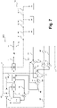
- FIG 7 a further steam cracking arrangement 2600 according to an embodiment of the present invention is illustrated.
- the explanations relating to the steam cracking arrangement 2200 according to Figure 3 based on the explanations for the steam cracking arrangement 2100 according to Figure 2 apply to the steam cracking arrangement 2600 according to Figure 7 and only differences will be explained below.
- Boiler feed water BF is therefore heated in heat exchanger X3 only, particularly to a temperature level of about 260°C, before being passed to the steam drum 31.
- a further heat exchanger X4 is provided, heating the feed hydrocarbons further before being mixed with the process steam PS in the mixing nozzle M.
- the process steam PS is likewise, in a further heat exchanger X5, heated before.
- the heat exchangers X2, X4 and X5 are operated with saturated steam SS and condensate streams are collected before being, as described before, used in the heat exchangers X1 and X3.
- process steam PS is initially provided at a temperature level of particularly about 180°C.
- the temperature level of the process stream PR downstream of the heat exchanger X2 is particularly about 300°C.
- Heating in the electric heater E1 is p articularly performed to a temperature level of about 630°C.
- the process gas P E effluent is withdrawn from the electric cracking furnace 210 at a temperature level of particularly about 870°C, from the quench exchanger 21 at a temperature level of particularly about 600°C, from the first quench exchanger 22 at a temperature level of particularly about 390°C, from the quench exchanger 22a at a temperature level of particularly about 380°C and from the oil quench 25 at a further suitable temperature level.
- the saturated steam generated in the steam drum 21 is provided at a pressure level of particularly about 122 bar absolute pressure and at a temperature level of particularly about 325°C.
- the superheated high pressure steam SU downstream of the quench exchanger 22a is provided at a pressure level of particularly about 121 bar absolute pressure and at a temperature level of particularly about 380°C.
- FIG 8 a further steam cracking arrangement 2700 according to an embodiment of the present invention is illustrated.
- the explanations relating to the steam cracking arrangement 2600 according to Figure 7 based on the explanations for the steam cracking arrangement 2100 according to Figure 2 apply to the steam cracking arrangement 2700 according to Figure 8 and only differences will be explained below.
- process steam PS is successively admixed to the feed hydrocarbons HC in a first and a second mixing nozzle M1, M2, where the process steam PS admixed in the second mixing nozzle M2 is further heated in a further electric heater E3.
- Figures 7 and 8 show exemplary embodiments of the present invention as applied for an electric furnace 210 operating on liquid feedstock and heavy liquid feedstock, respectively.
- the feed preheating section is typically more complex, featuring e.g. additional feed preheating steps (see Figures 7 and 8 , incl. electric process steam superheater usage for heavy liquid feedstocks) and/or one or more process steam superheating steps in multiflow heat exchangers.
- the embodiments shown in Figures 7 and 8 are straightforward adaptations of the embodiment shown in Figure 2 . Consequently, the variants presented by the embodiments shown in Figures 3 to 5 can analogously be applied to liquid feed furnaces as shown in Figures 7 and 8 , as they were applied to the gas feed furnace of Figure 2 .
- FIG 9 a further steam cracking arrangement 2800 according to an embodiment of the present invention is illustrated.
- the explanations relating to the steam cracking arrangement 2700 according to Figure 8 based on the explanations for the steam cracking arrangement 2100 according to Figure 2 apply to the steam cracking arrangement 2800 according to Figure 9 and only differences will be explained below.
- Figure 9 shows a process variant for a heavy liquid feed furnace analogous to the gas feed variant shown in Figure 4 (with the quench exchanger 21 designed as feed-effluent exchanger).
- FIG 10 a Mollier (enthalpy/entropy) diagram with an entropy s in kJ/(K*kg) displayed on the horizontal axis and an enthalpy h in kJ/kg displayed on the vertical axis is shown for water.
- a point 71 a moderate superheating as used according to embodiments of the present invention is indicated while with a point 72, a high superheating as used according to the prior art is indicated.
- an exemplary temperature evolution curve 81 of such an isenthalpic state change is shown in Figure 11 for a pressure range between 20 and 160 bar absolute pressure, altogether with corresponding most preferred curve envelopes 82 and 83 (with + 20 K and + 80 K dew point margins).
- an absolute pressure in bar is indicated on the horizontal axis and a temperature in °C is indic ated on the vertical axis.
Landscapes
- Chemical & Material Sciences (AREA)
- Engineering & Computer Science (AREA)
- Oil, Petroleum & Natural Gas (AREA)
- Physics & Mathematics (AREA)
- Thermal Sciences (AREA)
- Chemical Kinetics & Catalysis (AREA)
- General Chemical & Material Sciences (AREA)
- Organic Chemistry (AREA)
- Combustion & Propulsion (AREA)
- Mechanical Engineering (AREA)
- General Engineering & Computer Science (AREA)
- Life Sciences & Earth Sciences (AREA)
- Sustainable Development (AREA)
- Sustainable Energy (AREA)
- Production Of Liquid Hydrocarbon Mixture For Refining Petroleum (AREA)
- Physical Or Chemical Processes And Apparatus (AREA)
Priority Applications (10)
| Application Number | Priority Date | Filing Date | Title |
|---|---|---|---|
| EP21161780.8A EP4056894A1 (en) | 2021-03-10 | 2021-03-10 | Method and system for steamcracking |
| EP22710615.0A EP4305345B1 (en) | 2021-03-10 | 2022-03-08 | Method and system for steamcracking |
| CA3211811A CA3211811A1 (en) | 2021-03-10 | 2022-03-08 | Method and system for steamcracking |
| JP2023555250A JP2024511735A (ja) | 2021-03-10 | 2022-03-08 | スチームクラッキングのための方法及びシステム |
| US18/548,888 US20240158700A1 (en) | 2021-03-10 | 2022-03-08 | Method and System for Steamcracking |
| CN202280020183.6A CN116981880A (zh) | 2021-03-10 | 2022-03-08 | 用于蒸汽裂解的方法和系统 |
| PCT/EP2022/055878 WO2022189424A1 (en) | 2021-03-10 | 2022-03-08 | Method and system for steamcracking |
| KR1020237034425A KR20230155547A (ko) | 2021-03-10 | 2022-03-08 | 증기 분해 방법 및 시스템 |
| BR112023017590A BR112023017590A2 (pt) | 2021-03-10 | 2022-03-08 | Método e sistema para craqueamento a vapor |
| AU2022235047A AU2022235047A1 (en) | 2021-03-10 | 2022-03-08 | Method and system for steamcracking |
Applications Claiming Priority (1)
| Application Number | Priority Date | Filing Date | Title |
|---|---|---|---|
| EP21161780.8A EP4056894A1 (en) | 2021-03-10 | 2021-03-10 | Method and system for steamcracking |
Publications (1)
| Publication Number | Publication Date |
|---|---|
| EP4056894A1 true EP4056894A1 (en) | 2022-09-14 |
Family
ID=74870715
Family Applications (2)
| Application Number | Title | Priority Date | Filing Date |
|---|---|---|---|
| EP21161780.8A Withdrawn EP4056894A1 (en) | 2021-03-10 | 2021-03-10 | Method and system for steamcracking |
| EP22710615.0A Active EP4305345B1 (en) | 2021-03-10 | 2022-03-08 | Method and system for steamcracking |
Family Applications After (1)
| Application Number | Title | Priority Date | Filing Date |
|---|---|---|---|
| EP22710615.0A Active EP4305345B1 (en) | 2021-03-10 | 2022-03-08 | Method and system for steamcracking |
Country Status (9)
| Country | Link |
|---|---|
| US (1) | US20240158700A1 (ko) |
| EP (2) | EP4056894A1 (ko) |
| JP (1) | JP2024511735A (ko) |
| KR (1) | KR20230155547A (ko) |
| CN (1) | CN116981880A (ko) |
| AU (1) | AU2022235047A1 (ko) |
| BR (1) | BR112023017590A2 (ko) |
| CA (1) | CA3211811A1 (ko) |
| WO (1) | WO2022189424A1 (ko) |
Cited By (1)
| Publication number | Priority date | Publication date | Assignee | Title |
|---|---|---|---|---|
| WO2024121627A1 (en) * | 2022-12-06 | 2024-06-13 | Technip Energies France | Efficient cracking furnace system with reduced emission of co2 |
Citations (15)
| Publication number | Priority date | Publication date | Assignee | Title |
|---|---|---|---|---|
| DE710185C (de) | 1937-11-19 | 1941-09-06 | Siemens Reiniger Werke Akt Ges | Einrichtung zum Bestrahlen mit therapeutisch wirksamen Strahlen |
| DE1615278A1 (de) | 1967-06-30 | 1970-07-23 | Gefi Ges F Industriewaerme Mbh | Elektrischer Widerstandsofen,insbesondere zur Erhitzung gasfoermiger Medien |
| DE2362628A1 (de) | 1973-12-17 | 1975-06-19 | Linde Ag | Rohrofen |
| DE3334334A1 (de) | 1983-09-22 | 1985-04-11 | Hucke, Hans, Pratteln, Basel | Heizvorrichtung fuer das aufheizen eines in einem elektrisch betriebenen durchstroemelement enthaltenen waermetraegers |
| DE4128180A1 (de) * | 1991-08-24 | 1993-02-25 | Herrmann Eduart Obert | Transportable anlage zur rueckstandsarmen aufbereitung von altoel, rueckstandsoelen und anderen schweren oelen zu dieseloel und benzin mit einem softcrackingverfahren |
| US20060116543A1 (en) * | 1999-07-07 | 2006-06-01 | Naphtachimie S.A. & Bp Chemicals Limited | Method and apparatus for steam cracking hydrocarbons |
| WO2014090914A1 (de) | 2012-12-13 | 2014-06-19 | Basf Se | Verfahren zur durchführung wärmeverbrauchender prozesse |
| WO2015197181A1 (de) | 2014-06-26 | 2015-12-30 | Linde Aktiengesellschaft | Einrichtung und verfahren zum heizen eines fluides in einer rohrleitung mit drehstrom |
| EP3075704A1 (de) | 2015-03-31 | 2016-10-05 | Linde Aktiengesellschaft | Ofen mit elektrisch sowie mittels brennstoff beheizbaren reaktorrohren zur dampfreformierung eines kohlenwasserstoffhaltigen einsatzes |
| EP3249027A1 (de) | 2016-05-25 | 2017-11-29 | Linde Aktiengesellschaft | Emissionsreduziertes verfahren zur herstellung von olefinen |
| EP3249028A1 (de) | 2016-05-25 | 2017-11-29 | Linde Aktiengesellschaft | Emissionsreduziertes verfahren zur herstellung von olefinen |
| WO2020035575A1 (de) | 2018-08-16 | 2020-02-20 | Basf Se | Einrichtung und verfahren zum erhitzen eines fluides in einer rohrleitung mit gleichstrom |
| US20200172814A1 (en) * | 2017-06-16 | 2020-06-04 | Technip France | Cracking furnace system and method for cracking hydrocarbon feedstock therein |
| WO2020150244A1 (en) | 2019-01-15 | 2020-07-23 | Sabic Global Technologies, B.V. | Use of renewable energy in olefin synthesis |
| EP3748138A1 (en) * | 2019-06-06 | 2020-12-09 | Technip France | Method for driving machines in an ethylene plant steam generation circuit, and integrated ethylene and power plant system |
-
2021
- 2021-03-10 EP EP21161780.8A patent/EP4056894A1/en not_active Withdrawn
-
2022
- 2022-03-08 EP EP22710615.0A patent/EP4305345B1/en active Active
- 2022-03-08 AU AU2022235047A patent/AU2022235047A1/en active Pending
- 2022-03-08 BR BR112023017590A patent/BR112023017590A2/pt unknown
- 2022-03-08 CA CA3211811A patent/CA3211811A1/en active Pending
- 2022-03-08 CN CN202280020183.6A patent/CN116981880A/zh active Pending
- 2022-03-08 KR KR1020237034425A patent/KR20230155547A/ko unknown
- 2022-03-08 US US18/548,888 patent/US20240158700A1/en active Pending
- 2022-03-08 WO PCT/EP2022/055878 patent/WO2022189424A1/en active Application Filing
- 2022-03-08 JP JP2023555250A patent/JP2024511735A/ja active Pending
Patent Citations (17)
| Publication number | Priority date | Publication date | Assignee | Title |
|---|---|---|---|---|
| DE710185C (de) | 1937-11-19 | 1941-09-06 | Siemens Reiniger Werke Akt Ges | Einrichtung zum Bestrahlen mit therapeutisch wirksamen Strahlen |
| DE1615278A1 (de) | 1967-06-30 | 1970-07-23 | Gefi Ges F Industriewaerme Mbh | Elektrischer Widerstandsofen,insbesondere zur Erhitzung gasfoermiger Medien |
| DE2362628A1 (de) | 1973-12-17 | 1975-06-19 | Linde Ag | Rohrofen |
| DE3334334A1 (de) | 1983-09-22 | 1985-04-11 | Hucke, Hans, Pratteln, Basel | Heizvorrichtung fuer das aufheizen eines in einem elektrisch betriebenen durchstroemelement enthaltenen waermetraegers |
| DE4128180A1 (de) * | 1991-08-24 | 1993-02-25 | Herrmann Eduart Obert | Transportable anlage zur rueckstandsarmen aufbereitung von altoel, rueckstandsoelen und anderen schweren oelen zu dieseloel und benzin mit einem softcrackingverfahren |
| US20060116543A1 (en) * | 1999-07-07 | 2006-06-01 | Naphtachimie S.A. & Bp Chemicals Limited | Method and apparatus for steam cracking hydrocarbons |
| WO2014090914A1 (de) | 2012-12-13 | 2014-06-19 | Basf Se | Verfahren zur durchführung wärmeverbrauchender prozesse |
| WO2015197181A1 (de) | 2014-06-26 | 2015-12-30 | Linde Aktiengesellschaft | Einrichtung und verfahren zum heizen eines fluides in einer rohrleitung mit drehstrom |
| EP3075704A1 (de) | 2015-03-31 | 2016-10-05 | Linde Aktiengesellschaft | Ofen mit elektrisch sowie mittels brennstoff beheizbaren reaktorrohren zur dampfreformierung eines kohlenwasserstoffhaltigen einsatzes |
| EP3249027A1 (de) | 2016-05-25 | 2017-11-29 | Linde Aktiengesellschaft | Emissionsreduziertes verfahren zur herstellung von olefinen |
| EP3249028A1 (de) | 2016-05-25 | 2017-11-29 | Linde Aktiengesellschaft | Emissionsreduziertes verfahren zur herstellung von olefinen |
| US20200172814A1 (en) * | 2017-06-16 | 2020-06-04 | Technip France | Cracking furnace system and method for cracking hydrocarbon feedstock therein |
| WO2020035575A1 (de) | 2018-08-16 | 2020-02-20 | Basf Se | Einrichtung und verfahren zum erhitzen eines fluides in einer rohrleitung mit gleichstrom |
| WO2020150244A1 (en) | 2019-01-15 | 2020-07-23 | Sabic Global Technologies, B.V. | Use of renewable energy in olefin synthesis |
| WO2020150249A1 (en) | 2019-01-15 | 2020-07-23 | Sabic Global Technologies, B.V. | Use of intermittent energy in the production of chemicals |
| WO2020150248A1 (en) | 2019-01-15 | 2020-07-23 | Sabic Global Technologies, B.V. | Use of renewable energy in the production of chemicals |
| EP3748138A1 (en) * | 2019-06-06 | 2020-12-09 | Technip France | Method for driving machines in an ethylene plant steam generation circuit, and integrated ethylene and power plant system |
Non-Patent Citations (1)
| Title |
|---|
| "Ullmann's Encyclopedia of Industrial Chemistry", 15 April 2009, article "Ethylene" |
Cited By (1)
| Publication number | Priority date | Publication date | Assignee | Title |
|---|---|---|---|---|
| WO2024121627A1 (en) * | 2022-12-06 | 2024-06-13 | Technip Energies France | Efficient cracking furnace system with reduced emission of co2 |
Also Published As
| Publication number | Publication date |
|---|---|
| WO2022189424A1 (en) | 2022-09-15 |
| AU2022235047A1 (en) | 2023-09-07 |
| BR112023017590A2 (pt) | 2023-11-07 |
| CN116981880A (zh) | 2023-10-31 |
| US20240158700A1 (en) | 2024-05-16 |
| JP2024511735A (ja) | 2024-03-15 |
| KR20230155547A (ko) | 2023-11-10 |
| EP4305345B1 (en) | 2024-09-25 |
| CA3211811A1 (en) | 2022-09-15 |
| EP4305345A1 (en) | 2024-01-17 |
Similar Documents
| Publication | Publication Date | Title |
|---|---|---|
| RU2764677C2 (ru) | Система печи для крекинга и способ крекинга углеводородного сырья в ней | |
| EP4305343B1 (en) | Method and system for steamcracking | |
| DK2614033T3 (en) | Process and apparatus for producing process steam and boiler feed water in a heatable reforming reactor for the production of synthesis gas | |
| KR20220107064A (ko) | 탄화수소 처리 설비의 열 통합 | |
| EP4305345B1 (en) | Method and system for steamcracking | |
| CN105189417B (zh) | 用于降低使用共沸水/乙苯进料汽化生产苯乙烯单体的能量消耗的方法 | |
| EP4305344B1 (en) | Method and system for steamcracking | |
| WO2022268706A1 (en) | Olefins production process | |
| WO2024052486A1 (en) | Method and system for steam cracking | |
| CN117295806A (zh) | 用于蒸汽裂解的方法和设备 | |
| US11618857B1 (en) | Electric furnace for cracking hydrocarbon feedstock with heat recovery | |
| WO2024196383A1 (en) | Electric furnace for cracking hydrocarbon feedstock with heat recovery | |
| KR20240090391A (ko) | 전동식 열분해 반응기와 공급물-유출물 열 교환기를 포함하는 에틸렌 플랜트 | |
| CN117545824A (zh) | 烯烃生产方法 | |
| CN111032831A (zh) | 裂化炉系统和用于在其中裂化烃原料的方法 |
Legal Events
| Date | Code | Title | Description |
|---|---|---|---|
| PUAI | Public reference made under article 153(3) epc to a published international application that has entered the european phase |
Free format text: ORIGINAL CODE: 0009012 |
|
| STAA | Information on the status of an ep patent application or granted ep patent |
Free format text: STATUS: THE APPLICATION HAS BEEN PUBLISHED |
|
| AK | Designated contracting states |
Kind code of ref document: A1 Designated state(s): AL AT BE BG CH CY CZ DE DK EE ES FI FR GB GR HR HU IE IS IT LI LT LU LV MC MK MT NL NO PL PT RO RS SE SI SK SM TR |
|
| STAA | Information on the status of an ep patent application or granted ep patent |
Free format text: STATUS: THE APPLICATION IS DEEMED TO BE WITHDRAWN |
|
| 18D | Application deemed to be withdrawn |
Effective date: 20230315 |