EP4056831A1 - Method for controlling internal combustion engine, and device for controlling internal combustion engine - Google Patents
Method for controlling internal combustion engine, and device for controlling internal combustion engine Download PDFInfo
- Publication number
- EP4056831A1 EP4056831A1 EP19951851.5A EP19951851A EP4056831A1 EP 4056831 A1 EP4056831 A1 EP 4056831A1 EP 19951851 A EP19951851 A EP 19951851A EP 4056831 A1 EP4056831 A1 EP 4056831A1
- Authority
- EP
- European Patent Office
- Prior art keywords
- internal combustion
- combustion engine
- damper
- torque
- displacement
- Prior art date
- Legal status (The legal status is an assumption and is not a legal conclusion. Google has not performed a legal analysis and makes no representation as to the accuracy of the status listed.)
- Withdrawn
Links
Images


Classifications
-
- B—PERFORMING OPERATIONS; TRANSPORTING
- B60—VEHICLES IN GENERAL
- B60W—CONJOINT CONTROL OF VEHICLE SUB-UNITS OF DIFFERENT TYPE OR DIFFERENT FUNCTION; CONTROL SYSTEMS SPECIALLY ADAPTED FOR HYBRID VEHICLES; ROAD VEHICLE DRIVE CONTROL SYSTEMS FOR PURPOSES NOT RELATED TO THE CONTROL OF A PARTICULAR SUB-UNIT
- B60W20/00—Control systems specially adapted for hybrid vehicles
- B60W20/10—Controlling the power contribution of each of the prime movers to meet required power demand
- B60W20/15—Control strategies specially adapted for achieving a particular effect
- B60W20/17—Control strategies specially adapted for achieving a particular effect for noise reduction
-
- B—PERFORMING OPERATIONS; TRANSPORTING
- B60—VEHICLES IN GENERAL
- B60K—ARRANGEMENT OR MOUNTING OF PROPULSION UNITS OR OF TRANSMISSIONS IN VEHICLES; ARRANGEMENT OR MOUNTING OF PLURAL DIVERSE PRIME-MOVERS IN VEHICLES; AUXILIARY DRIVES FOR VEHICLES; INSTRUMENTATION OR DASHBOARDS FOR VEHICLES; ARRANGEMENTS IN CONNECTION WITH COOLING, AIR INTAKE, GAS EXHAUST OR FUEL SUPPLY OF PROPULSION UNITS IN VEHICLES
- B60K6/00—Arrangement or mounting of plural diverse prime-movers for mutual or common propulsion, e.g. hybrid propulsion systems comprising electric motors and internal combustion engines
- B60K6/20—Arrangement or mounting of plural diverse prime-movers for mutual or common propulsion, e.g. hybrid propulsion systems comprising electric motors and internal combustion engines the prime-movers consisting of electric motors and internal combustion engines, e.g. HEVs
- B60K6/42—Arrangement or mounting of plural diverse prime-movers for mutual or common propulsion, e.g. hybrid propulsion systems comprising electric motors and internal combustion engines the prime-movers consisting of electric motors and internal combustion engines, e.g. HEVs characterised by the architecture of the hybrid electric vehicle
- B60K6/46—Series type
-
- B—PERFORMING OPERATIONS; TRANSPORTING
- B60—VEHICLES IN GENERAL
- B60W—CONJOINT CONTROL OF VEHICLE SUB-UNITS OF DIFFERENT TYPE OR DIFFERENT FUNCTION; CONTROL SYSTEMS SPECIALLY ADAPTED FOR HYBRID VEHICLES; ROAD VEHICLE DRIVE CONTROL SYSTEMS FOR PURPOSES NOT RELATED TO THE CONTROL OF A PARTICULAR SUB-UNIT
- B60W10/00—Conjoint control of vehicle sub-units of different type or different function
- B60W10/04—Conjoint control of vehicle sub-units of different type or different function including control of propulsion units
- B60W10/06—Conjoint control of vehicle sub-units of different type or different function including control of propulsion units including control of combustion engines
-
- B—PERFORMING OPERATIONS; TRANSPORTING
- B60—VEHICLES IN GENERAL
- B60W—CONJOINT CONTROL OF VEHICLE SUB-UNITS OF DIFFERENT TYPE OR DIFFERENT FUNCTION; CONTROL SYSTEMS SPECIALLY ADAPTED FOR HYBRID VEHICLES; ROAD VEHICLE DRIVE CONTROL SYSTEMS FOR PURPOSES NOT RELATED TO THE CONTROL OF A PARTICULAR SUB-UNIT
- B60W10/00—Conjoint control of vehicle sub-units of different type or different function
- B60W10/04—Conjoint control of vehicle sub-units of different type or different function including control of propulsion units
- B60W10/08—Conjoint control of vehicle sub-units of different type or different function including control of propulsion units including control of electric propulsion units, e.g. motors or generators
-
- B—PERFORMING OPERATIONS; TRANSPORTING
- B60—VEHICLES IN GENERAL
- B60W—CONJOINT CONTROL OF VEHICLE SUB-UNITS OF DIFFERENT TYPE OR DIFFERENT FUNCTION; CONTROL SYSTEMS SPECIALLY ADAPTED FOR HYBRID VEHICLES; ROAD VEHICLE DRIVE CONTROL SYSTEMS FOR PURPOSES NOT RELATED TO THE CONTROL OF A PARTICULAR SUB-UNIT
- B60W20/00—Control systems specially adapted for hybrid vehicles
- B60W20/10—Controlling the power contribution of each of the prime movers to meet required power demand
- B60W20/15—Control strategies specially adapted for achieving a particular effect
-
- B—PERFORMING OPERATIONS; TRANSPORTING
- B60—VEHICLES IN GENERAL
- B60W—CONJOINT CONTROL OF VEHICLE SUB-UNITS OF DIFFERENT TYPE OR DIFFERENT FUNCTION; CONTROL SYSTEMS SPECIALLY ADAPTED FOR HYBRID VEHICLES; ROAD VEHICLE DRIVE CONTROL SYSTEMS FOR PURPOSES NOT RELATED TO THE CONTROL OF A PARTICULAR SUB-UNIT
- B60W30/00—Purposes of road vehicle drive control systems not related to the control of a particular sub-unit, e.g. of systems using conjoint control of vehicle sub-units
- B60W30/18—Propelling the vehicle
- B60W30/184—Preventing damage resulting from overload or excessive wear of the driveline
- B60W30/1846—Preventing of breakage of drive line components, e.g. parts of the gearing
-
- B—PERFORMING OPERATIONS; TRANSPORTING
- B60—VEHICLES IN GENERAL
- B60W—CONJOINT CONTROL OF VEHICLE SUB-UNITS OF DIFFERENT TYPE OR DIFFERENT FUNCTION; CONTROL SYSTEMS SPECIALLY ADAPTED FOR HYBRID VEHICLES; ROAD VEHICLE DRIVE CONTROL SYSTEMS FOR PURPOSES NOT RELATED TO THE CONTROL OF A PARTICULAR SUB-UNIT
- B60W30/00—Purposes of road vehicle drive control systems not related to the control of a particular sub-unit, e.g. of systems using conjoint control of vehicle sub-units
- B60W30/18—Propelling the vehicle
- B60W30/20—Reducing vibrations in the driveline
-
- F—MECHANICAL ENGINEERING; LIGHTING; HEATING; WEAPONS; BLASTING
- F02—COMBUSTION ENGINES; HOT-GAS OR COMBUSTION-PRODUCT ENGINE PLANTS
- F02D—CONTROLLING COMBUSTION ENGINES
- F02D29/00—Controlling engines, such controlling being peculiar to the devices driven thereby, the devices being other than parts or accessories essential to engine operation, e.g. controlling of engines by signals external thereto
- F02D29/02—Controlling engines, such controlling being peculiar to the devices driven thereby, the devices being other than parts or accessories essential to engine operation, e.g. controlling of engines by signals external thereto peculiar to engines driving vehicles; peculiar to engines driving variable pitch propellers
-
- F—MECHANICAL ENGINEERING; LIGHTING; HEATING; WEAPONS; BLASTING
- F02—COMBUSTION ENGINES; HOT-GAS OR COMBUSTION-PRODUCT ENGINE PLANTS
- F02D—CONTROLLING COMBUSTION ENGINES
- F02D29/00—Controlling engines, such controlling being peculiar to the devices driven thereby, the devices being other than parts or accessories essential to engine operation, e.g. controlling of engines by signals external thereto
- F02D29/06—Controlling engines, such controlling being peculiar to the devices driven thereby, the devices being other than parts or accessories essential to engine operation, e.g. controlling of engines by signals external thereto peculiar to engines driving electric generators
-
- F—MECHANICAL ENGINEERING; LIGHTING; HEATING; WEAPONS; BLASTING
- F16—ENGINEERING ELEMENTS AND UNITS; GENERAL MEASURES FOR PRODUCING AND MAINTAINING EFFECTIVE FUNCTIONING OF MACHINES OR INSTALLATIONS; THERMAL INSULATION IN GENERAL
- F16F—SPRINGS; SHOCK-ABSORBERS; MEANS FOR DAMPING VIBRATION
- F16F15/00—Suppression of vibrations in systems; Means or arrangements for avoiding or reducing out-of-balance forces, e.g. due to motion
- F16F15/10—Suppression of vibrations in rotating systems by making use of members moving with the system
- F16F15/12—Suppression of vibrations in rotating systems by making use of members moving with the system using elastic members or friction-damping members, e.g. between a rotating shaft and a gyratory mass mounted thereon
- F16F15/121—Suppression of vibrations in rotating systems by making use of members moving with the system using elastic members or friction-damping members, e.g. between a rotating shaft and a gyratory mass mounted thereon using springs as elastic members, e.g. metallic springs
- F16F15/1217—Motion-limiting means, e.g. means for locking the spring unit in pre-defined positions
-
- F—MECHANICAL ENGINEERING; LIGHTING; HEATING; WEAPONS; BLASTING
- F16—ENGINEERING ELEMENTS AND UNITS; GENERAL MEASURES FOR PRODUCING AND MAINTAINING EFFECTIVE FUNCTIONING OF MACHINES OR INSTALLATIONS; THERMAL INSULATION IN GENERAL
- F16F—SPRINGS; SHOCK-ABSORBERS; MEANS FOR DAMPING VIBRATION
- F16F15/00—Suppression of vibrations in systems; Means or arrangements for avoiding or reducing out-of-balance forces, e.g. due to motion
- F16F15/10—Suppression of vibrations in rotating systems by making use of members moving with the system
- F16F15/12—Suppression of vibrations in rotating systems by making use of members moving with the system using elastic members or friction-damping members, e.g. between a rotating shaft and a gyratory mass mounted thereon
- F16F15/121—Suppression of vibrations in rotating systems by making use of members moving with the system using elastic members or friction-damping members, e.g. between a rotating shaft and a gyratory mass mounted thereon using springs as elastic members, e.g. metallic springs
- F16F15/123—Wound springs
- F16F15/1238—Wound springs with pre-damper, i.e. additional set of springs between flange of main damper and hub
-
- B—PERFORMING OPERATIONS; TRANSPORTING
- B60—VEHICLES IN GENERAL
- B60W—CONJOINT CONTROL OF VEHICLE SUB-UNITS OF DIFFERENT TYPE OR DIFFERENT FUNCTION; CONTROL SYSTEMS SPECIALLY ADAPTED FOR HYBRID VEHICLES; ROAD VEHICLE DRIVE CONTROL SYSTEMS FOR PURPOSES NOT RELATED TO THE CONTROL OF A PARTICULAR SUB-UNIT
- B60W30/00—Purposes of road vehicle drive control systems not related to the control of a particular sub-unit, e.g. of systems using conjoint control of vehicle sub-units
- B60W30/18—Propelling the vehicle
- B60W30/20—Reducing vibrations in the driveline
- B60W2030/206—Reducing vibrations in the driveline related or induced by the engine
-
- B—PERFORMING OPERATIONS; TRANSPORTING
- B60—VEHICLES IN GENERAL
- B60W—CONJOINT CONTROL OF VEHICLE SUB-UNITS OF DIFFERENT TYPE OR DIFFERENT FUNCTION; CONTROL SYSTEMS SPECIALLY ADAPTED FOR HYBRID VEHICLES; ROAD VEHICLE DRIVE CONTROL SYSTEMS FOR PURPOSES NOT RELATED TO THE CONTROL OF A PARTICULAR SUB-UNIT
- B60W2710/00—Output or target parameters relating to a particular sub-units
- B60W2710/06—Combustion engines, Gas turbines
- B60W2710/0666—Engine torque
-
- F—MECHANICAL ENGINEERING; LIGHTING; HEATING; WEAPONS; BLASTING
- F02—COMBUSTION ENGINES; HOT-GAS OR COMBUSTION-PRODUCT ENGINE PLANTS
- F02D—CONTROLLING COMBUSTION ENGINES
- F02D2250/00—Engine control related to specific problems or objectives
- F02D2250/18—Control of the engine output torque
- F02D2250/26—Control of the engine output torque by applying a torque limit
-
- F—MECHANICAL ENGINEERING; LIGHTING; HEATING; WEAPONS; BLASTING
- F16—ENGINEERING ELEMENTS AND UNITS; GENERAL MEASURES FOR PRODUCING AND MAINTAINING EFFECTIVE FUNCTIONING OF MACHINES OR INSTALLATIONS; THERMAL INSULATION IN GENERAL
- F16D—COUPLINGS FOR TRANSMITTING ROTATION; CLUTCHES; BRAKES
- F16D3/00—Yielding couplings, i.e. with means permitting movement between the connected parts during the drive
- F16D3/02—Yielding couplings, i.e. with means permitting movement between the connected parts during the drive adapted to specific functions
- F16D3/12—Yielding couplings, i.e. with means permitting movement between the connected parts during the drive adapted to specific functions specially adapted for accumulation of energy to absorb shocks or vibration
-
- Y—GENERAL TAGGING OF NEW TECHNOLOGICAL DEVELOPMENTS; GENERAL TAGGING OF CROSS-SECTIONAL TECHNOLOGIES SPANNING OVER SEVERAL SECTIONS OF THE IPC; TECHNICAL SUBJECTS COVERED BY FORMER USPC CROSS-REFERENCE ART COLLECTIONS [XRACs] AND DIGESTS
- Y02—TECHNOLOGIES OR APPLICATIONS FOR MITIGATION OR ADAPTATION AGAINST CLIMATE CHANGE
- Y02T—CLIMATE CHANGE MITIGATION TECHNOLOGIES RELATED TO TRANSPORTATION
- Y02T10/00—Road transport of goods or passengers
- Y02T10/60—Other road transportation technologies with climate change mitigation effect
- Y02T10/62—Hybrid vehicles
Definitions
- the present invention relates to an internal combustion engine control.
- JP2009-281189A discloses a technique of limiting transmission of an excessive torque in the event of an engine misfire or the like by using a damper installed with a torque limiter.
- JP2009-281189A it is necessary to adopt a damper installed with a torque limiter as a damper in order to limit transmission of an excessive torque.
- a control method for an internal combustion engine is a control method for the internal combustion engine which includes an electric generator driven by a power of the internal combustion engine, and a damper provided between the internal combustion engine and the electric generator in a power transmission path.
- a maximum value of a torque fluctuation generated in an event of a misfire occurring in a cylinder of the internal combustion engine is larger than a value at which a displacement of the damper is allowed to be suppressed to be smaller than a displacement at which abutting occurs on a stopper of the damper by a counter torque of the electric generator.
- the control method includes limiting a torque of the internal combustion engine within a range in which a displacement of the damper is allowed to be controlled to be smaller than a displacement at which abutting occurs on the stopper by a counter torque of the electric generator.
- a control device for an internal combustion engine corresponding to the control method for the internal combustion engine mentioned above is provided.
- FIG. 1 is a schematic configuration diagram illustrating main parts of the vehicle 1.
- the vehicle 1 has an internal combustion engine 3, a power generation motor 4, a battery 5, a driving motor 2, and a controller 7.
- the internal combustion engine 3 may be either a gasoline engine or a diesel engine.
- a flywheel 3b is provided on an output shaft 3a of the internal combustion engine 3.
- the flywheel 3b serves as a rotating member provided between the internal combustion engine 3 and the damper 30 described below in a power transmission path.
- the power generation motor 4 is driven by the power of the internal combustion engine 3 to generate electricity.
- the power generation motor 4 constitutes an electric generator.
- the battery 5 is charged with the electric power generated by the power generation motor 4 and the electric power regenerated by the driving motor 2 as described below.
- the driving motor 2 is driven by the electric power of the battery 5 to drive the driving wheels 6.
- the driving motor 2 also has a so-called regeneration function in which deceleration energy is regenerated as electric power as it rotates along with rotation of the driving wheels 6 during deceleration or the like.
- the controller 7 controls the driving motor 2, the internal combustion engine 3, and the power generation motor 4.
- the controller 7 includes a microcomputer provided with a central processing unit (CPU), a read-only memory (ROM), a random access memory (RAM), and an input/output interface (I/O interface). It is also possible to configure the controller 7 with a plurality of microcomputers.
- the controller 7 receives signals input from various sensors or switches such as a rotation speed sensor for detecting a rotation speed Ne of the internal combustion engine 3, an accelerator position sensor for detecting an accelerator position APO, and a vehicle speed sensor for detecting a vehicle speed VSP.
- the vehicle 1 has a first power transmission path 21 and a second power transmission path 22.
- the first power transmission path 21 transmits power between the driving motor 2 and the driving wheels 6.
- the second power transmission path 22 transmits power between the internal combustion engine 3 and the power generation motor 4.
- the first power transmission path 21 and the second power transmission path 22 are power transmission paths that are independent of each other, that is, power is not transmitted from one of the first power transmission path 21 and the second power transmission path 22 to the other.
- the first power transmission path 21 includes a first reduction gear 8 provided on the rotation shaft 2a of the driving motor 2, a second reduction gear 9 that meshes with the first reduction gear 8, a third reduction gear 10 that is provided coaxially with the second reduction gear 9 and meshes with a differential gear 12, and a differential gear 12 provided on a differential casing 11.
- the second power transmission path 22 includes a fourth reduction gear 16 provided on an output shaft 3a of the internal combustion engine 3, a fifth reduction gear 17 that meshes with the fourth reduction gear 16, and a sixth reduction gear 18 that is provided on the rotation shaft 4a of the power generation motor 4 and meshes with the fifth reduction gear 17.
- the fourth reduction gear 16, the fifth reduction gear 17, and the sixth reduction gear 18 constitute a gear train 19 provided between the internal combustion engine 3 and the power generation motor 4.
- a damper 30 is provided in the second power transmission path 22.
- the damper 30 is provided on the output shaft 3a of the internal combustion engine 3 and attenuates a torsional vibration of the output shaft 3a.
- Each of the first power transmission path 21 and the second power transmission path 22 does not have an element for blocking power transmission. That is, each of the first power transmission path 21 and the second power transmission path 22 has a state where power is transmittable at all times.
- the vehicle 1 having the aforementioned configuration is a series hybrid vehicle in which the driving motor 2 drives the driving wheels 6 by utilizing the electric power of the power generation motor 4 driven by the power of the internal combustion engine 3 to generate electricity.
- FIG. 2 is a diagram schematically illustrating a power transmission system of the second power transmission path 22 including the damper 30.
- the power of the internal combustion engine 3 is transmitted from the internal combustion engine 3, to the output shaft 3a, to the flywheel 3b, to the damper 30, to the output shaft 3a, to the gear train 19, to the rotation shaft 4a of the power generation motor 4, and to the power generation motor 4 in this order.
- the damper 30 includes a main damper 30a and a pre-damper 30b.
- the main damper 30a has a function of attenuating the torsional vibration with respect to the torque Te of the internal combustion engine 3 transmitted from the flywheel 3b.
- the pre-damper 30b has a function of attenuating the torsional vibration with respect to the torque Te transmitted from a first hub 31.
- the main damper 30a includes a first hub 31 and a main coil 33.
- the first hub 31 is provided rotatable by the main coil 33 within a predetermined angle range relative to the flywheel 3b.
- a plurality of main coils 33 are provided in the circumferential direction of the damper 30.
- the pre-damper 30b includes a second hub 32 and a pre-coil 34.
- the second hub 32 is provided rotatable by the pre-coil 34 within a predetermined angle range relative to the first hub 31.
- a plurality of pre-coils 34 are provided in the circumferential direction of the damper 30.
- a plurality of pre-coils 34 are set to have a smaller spring force than that of a plurality of main coils 33 depending on a compression displacement per unit length, and, for example, a coil having a lower spring constant than that of the main coil 33 is used as the pre-coil 34. Therefore, when the power of the internal combustion engine 3 is input to the damper 30, the pre-damper 30b first starts to attenuate the torsional vibration before the main damper 30a, and a relative rotation occurs between the first hub 31 and the second hub 32.
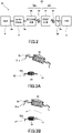
- FIG. 3A is a diagram illustrating a first state of the damper 30.
- FIG. 3B is a diagram illustrating a second state of the damper 30.
- FIGS. 3A and 3B show main parts of the damper 30 as seen along the axial direction of the output shaft 3a.
- both the main damper 30a and the pre-damper 30b are in the first state shown in FIG. 3A .
- compression occurs in the pre-coil 34 on the side where the spring constant is low, so that the first hub 31 starts to rotate relative to the second hub 32. That is, out of the main damper 30a and the pre-damper 30b, the pre-damper 30b first starts to attenuate the torsional vibration.
- the first hub 31 further rotates, as shown in FIG. 3B
- the first hub 31 abuts on the second stopper 32a provided on the second hub 32.
- the second stopper 32a regulates a relative rotation of the first hub 31 with respect to the second hub 32.
- the power of the internal combustion engine 3 is transmitted to the gear train 19.
- the main coil 33 is compressed in the main damper 30a, a relative rotation occurs between the first hub 31 and the flywheel 3b, so that the main damper 30a functions.
- the function of the main damper 30a is secured as long as the main coil 33 is not compressed to the state where abutting occurs on the first stopper 31a.
- the first stopper 31a regulates a relative rotation of the flywheel 3b with respect to the first hub 31.
- the flywheel 3b abuts on the first stopper 31a when there is an excessive input.
- the power of the internal combustion engine 3 may be transmitted from the flywheel 3b to the main damper 30a, for example, via a disk-shaped plate.
- the damper 30 may further have such a plate, and in this case, the plate may form a rotating member that abuts on the first stopper 30a.
- a resonance point is set to be lower than an idle rotation speed range of the internal combustion engine 3.
- the resonance point enters a normal operation range of the internal combustion engine 3 due to a decrease in the number of the ignited cylinders.
- the load caused by the excessive input may be applied to the first stopper 31a as resonance and divergence occur depending on the rotation speed Ne of the internal combustion engine 3.
- the damper 30 may be set as a damper installed with a torque limiter.
- abutting of the first stopper 31a may be prevented by suppressing the displacement of the main damper 30a to be smaller than a displacement at which abutting occurs on the first stopper 31a by a counter torque of the power generation motor 4.
- the maximum value of the fluctuation of the torque Te of the internal combustion engine 3 at which a misfire occurs in a cylinder is larger than a value at which a displacement of the main damper 30a can be suppressed to be smaller than a displacement at which abutting occurs on the first stopper 31a by the counter torque of the power generation motor 4. Therefore, in this case, it is difficult to prevent abutting of the first stopper 31a.
- the controller 7 limits the torque Te of the internal combustion engine 3 within a range in which a displacement of the main damper 30a can be controlled to be smaller than a displacement at which abutting occurs on the first stopper 31a by the counter torque of the power generation motor 4.
- FIG. 4A is a diagram illustrating an operation region of the internal combustion engine 3 including a fluctuation of the torque Te.
- FIG. 4B is a diagram illustrating a twist angle ⁇ of the main damper 30a depending on the rotation speed Ne.
- a case of the comparative example is also illustrated by the broken lines.
- a comparative example shows a case where the controller 7 does not limit the torque Te of the internal combustion engine 3.
- the internal combustion engine 3 is operated on the basis of a preset engine performance line E2.
- the operation region of the internal combustion engine 3 becomes the region RA2 having an extension above and below the engine performance line E2 due to a fluctuation of the torque Te.
- the twist angle ⁇ fluctuates within the region RB2 depending on the region RA2.
- the torque Te of the internal combustion engine 3 is limited as described above.
- the torque Te is limited as described above by operating the internal combustion engine 3 on the basis of the engine performance line E1 obtained by reducing the WOT torque Tew on the engine performance line E2 to a torque lower than the WOT torque Tew on the side where the rotation speed Ne is low.
- such an engine performance line E1 is an engine performance line in which the rotation speed Ne reaching the WOT torque Tew is set to a higher rotation speed Ne side as compared with the engine performance line E2.
- the torque Te is limited during the engine operation at all times. Therefore, the torque Te is limited depending on the operation of the internal combustion engine 3.
- the operation region of the internal combustion engine 3 becomes a region RA1 that does not reach the stopper torque Tes.
- the twist angle ⁇ fluctuates within the region RB1 corresponding to the region RA1, and does not reach the contact angle ⁇ s.
- the engine performance line E1 may be set in advance on the basis of the rotation speed Ne and the torque Te, for example, by using map data.
- the controller 7 configured to limit the torque Te as described above is configured to have a control unit.
- a maximum value of a torque fluctuation generated in the event of a misfire occurring in a cylinder of the internal combustion engine 3 is larger than a value at which a displacement of the main damper 30a of the damper 30 is allowed to be suppressed to be smaller than a displacement at which abutting occurs on the first stopper 31a by a counter torque of the power generation motor 4.
- control method of the internal combustion engine 3 includes limiting the torque Te of the internal combustion engine 3 within a range in which a displacement of the main damper 30a can be controlled to be smaller than a displacement at which abutting occurs on the first stopper 31a by the counter torque of the power generation motor 4.
- a load may be applied to the first stopper 31a between the occurrence of the misfire and the start of the torque Te limitation.
- the torque Te of the internal combustion engine 3 is limited depending on an operation of the internal combustion engine 3. Therefore, it is possible to avoid the occurrence of the load on the first stopper 31a by limiting the torque Te at all time.
- the damper 30 includes the main damper 30a and the pre-damper 30b.
- the first stopper 31a is provided in the first hub 31.
- the flywheel 3b provided between the internal combustion engine 3 and the damper 30 in the power transmission path abuts on the first stopper 31a.
- the internal combustion engine 3 is mounted on a vehicle 1 which serves as a series hybrid vehicle.
- vehicle 1 includes the driving motor 2 that drives the driving wheels 6 by the electric power generated by the power generation motor 4, the first power transmission path 21 for transmitting power between the driving motor 2 and the driving wheels 6, and the second power transmission path 22 for transmitting power between the internal combustion engine 3 and the power generation motor 4.
- the damper 30 is provided in the second power transmission path 22.
- the damper 30 includes the main damper 30a and the pre-damper 30b has been described.
- control method and the control unit of the internal combustion engine 3 are realized by a single controller 7 .
- control method and control unit of the internal combustion engine 3 may also be realized by, for example, a combination of a plurality of controllers.
Landscapes
- Engineering & Computer Science (AREA)
- Mechanical Engineering (AREA)
- Chemical & Material Sciences (AREA)
- Combustion & Propulsion (AREA)
- General Engineering & Computer Science (AREA)
- Transportation (AREA)
- Automation & Control Theory (AREA)
- Physics & Mathematics (AREA)
- Acoustics & Sound (AREA)
- Aviation & Aerospace Engineering (AREA)
- Hybrid Electric Vehicles (AREA)
- Control Of Vehicle Engines Or Engines For Specific Uses (AREA)
Abstract
Description
- The present invention relates to an internal combustion engine control.
-
JP2009-281189A - In
JP2009-281189A - In view of such a problem, it is therefore an object of the present invention to limit transmission of an excessive torque without adopting the torque limiter and reduce a load applied to a stopper of the damper.
- A control method for an internal combustion engine according to a certain aspect of the present invention is a control method for the internal combustion engine which includes an electric generator driven by a power of the internal combustion engine, and a damper provided between the internal combustion engine and the electric generator in a power transmission path. In the control method, a maximum value of a torque fluctuation generated in an event of a misfire occurring in a cylinder of the internal combustion engine is larger than a value at which a displacement of the damper is allowed to be suppressed to be smaller than a displacement at which abutting occurs on a stopper of the damper by a counter torque of the electric generator. The control method includes limiting a torque of the internal combustion engine within a range in which a displacement of the damper is allowed to be controlled to be smaller than a displacement at which abutting occurs on the stopper by a counter torque of the electric generator.
- According to another aspect of the present invention, a control device for an internal combustion engine corresponding to the control method for the internal combustion engine mentioned above is provided.
-
-
FIG. 1 is a schematic configuration diagram illustrating main parts of a vehicle. -
FIG. 2 is a diagram schematically illustrating a power transmission system of a second power transmission path. -
FIG. 3A is a diagram illustrating a first state of the damper. -
FIG. 3B is a diagram illustrating a second state of the damper. -
FIG. 4A is a diagram illustrating an operation region of an internal combustion engine including torque fluctuations. -
FIG. 4B is a diagram illustrating a twist angle of a main damper depending on a rotation speed. - Embodiments of the present invention will now be described with reference to the accompanying drawings.
-
FIG. 1 is a schematic configuration diagram illustrating main parts of the vehicle 1. The vehicle 1 has aninternal combustion engine 3, apower generation motor 4, abattery 5, a drivingmotor 2, and acontroller 7. - The
internal combustion engine 3 may be either a gasoline engine or a diesel engine. Aflywheel 3b is provided on anoutput shaft 3a of theinternal combustion engine 3. Theflywheel 3b serves as a rotating member provided between theinternal combustion engine 3 and thedamper 30 described below in a power transmission path. - The
power generation motor 4 is driven by the power of theinternal combustion engine 3 to generate electricity. Thepower generation motor 4 constitutes an electric generator. - The
battery 5 is charged with the electric power generated by thepower generation motor 4 and the electric power regenerated by the drivingmotor 2 as described below. - The driving
motor 2 is driven by the electric power of thebattery 5 to drive thedriving wheels 6. In addition, thedriving motor 2 also has a so-called regeneration function in which deceleration energy is regenerated as electric power as it rotates along with rotation of thedriving wheels 6 during deceleration or the like. - The
controller 7 controls thedriving motor 2, theinternal combustion engine 3, and thepower generation motor 4. Thecontroller 7 includes a microcomputer provided with a central processing unit (CPU), a read-only memory (ROM), a random access memory (RAM), and an input/output interface (I/O interface). It is also possible to configure thecontroller 7 with a plurality of microcomputers. Thecontroller 7 receives signals input from various sensors or switches such as a rotation speed sensor for detecting a rotation speed Ne of theinternal combustion engine 3, an accelerator position sensor for detecting an accelerator position APO, and a vehicle speed sensor for detecting a vehicle speed VSP. - The vehicle 1 has a first
power transmission path 21 and a secondpower transmission path 22. The firstpower transmission path 21 transmits power between the drivingmotor 2 and thedriving wheels 6. The secondpower transmission path 22 transmits power between theinternal combustion engine 3 and thepower generation motor 4. The firstpower transmission path 21 and the secondpower transmission path 22 are power transmission paths that are independent of each other, that is, power is not transmitted from one of the firstpower transmission path 21 and the secondpower transmission path 22 to the other. - The first
power transmission path 21 includes afirst reduction gear 8 provided on therotation shaft 2a of thedriving motor 2, asecond reduction gear 9 that meshes with thefirst reduction gear 8, athird reduction gear 10 that is provided coaxially with thesecond reduction gear 9 and meshes with adifferential gear 12, and adifferential gear 12 provided on adifferential casing 11. - The second
power transmission path 22 includes afourth reduction gear 16 provided on anoutput shaft 3a of theinternal combustion engine 3, afifth reduction gear 17 that meshes with thefourth reduction gear 16, and asixth reduction gear 18 that is provided on therotation shaft 4a of thepower generation motor 4 and meshes with thefifth reduction gear 17. Thefourth reduction gear 16, thefifth reduction gear 17, and thesixth reduction gear 18 constitute agear train 19 provided between theinternal combustion engine 3 and thepower generation motor 4. - A
damper 30 is provided in the secondpower transmission path 22. Thedamper 30 is provided on theoutput shaft 3a of theinternal combustion engine 3 and attenuates a torsional vibration of theoutput shaft 3a. - Each of the first
power transmission path 21 and the secondpower transmission path 22 does not have an element for blocking power transmission. That is, each of the firstpower transmission path 21 and the secondpower transmission path 22 has a state where power is transmittable at all times. - The vehicle 1 having the aforementioned configuration is a series hybrid vehicle in which the driving
motor 2 drives thedriving wheels 6 by utilizing the electric power of thepower generation motor 4 driven by the power of theinternal combustion engine 3 to generate electricity. -
FIG. 2 is a diagram schematically illustrating a power transmission system of the secondpower transmission path 22 including thedamper 30. In the secondpower transmission path 22, the power of theinternal combustion engine 3 is transmitted from theinternal combustion engine 3, to theoutput shaft 3a, to theflywheel 3b, to thedamper 30, to theoutput shaft 3a, to thegear train 19, to therotation shaft 4a of thepower generation motor 4, and to thepower generation motor 4 in this order. - The
damper 30 includes amain damper 30a and a pre-damper 30b. Themain damper 30a has a function of attenuating the torsional vibration with respect to the torque Te of theinternal combustion engine 3 transmitted from theflywheel 3b. The pre-damper 30b has a function of attenuating the torsional vibration with respect to the torque Te transmitted from afirst hub 31. - The
main damper 30a includes afirst hub 31 and amain coil 33. Thefirst hub 31 is provided rotatable by themain coil 33 within a predetermined angle range relative to theflywheel 3b. A plurality ofmain coils 33 are provided in the circumferential direction of thedamper 30. - The pre-damper 30b includes a
second hub 32 and a pre-coil 34. Thesecond hub 32 is provided rotatable by the pre-coil 34 within a predetermined angle range relative to thefirst hub 31. A plurality of pre-coils 34 are provided in the circumferential direction of thedamper 30. - A plurality of pre-coils 34 are set to have a smaller spring force than that of a plurality of
main coils 33 depending on a compression displacement per unit length, and, for example, a coil having a lower spring constant than that of themain coil 33 is used as the pre-coil 34. Therefore, when the power of theinternal combustion engine 3 is input to thedamper 30, the pre-damper 30b first starts to attenuate the torsional vibration before themain damper 30a, and a relative rotation occurs between thefirst hub 31 and thesecond hub 32. -
FIG. 3A is a diagram illustrating a first state of thedamper 30.FIG. 3B is a diagram illustrating a second state of thedamper 30.FIGS. 3A and 3B show main parts of thedamper 30 as seen along the axial direction of theoutput shaft 3a. - When the power of the
internal combustion engine 3 is not input to thedamper 30, both themain damper 30a and the pre-damper 30b are in the first state shown inFIG. 3A . Then, when the power of theinternal combustion engine 3 is input to thedamper 30 from this state, compression occurs in the pre-coil 34 on the side where the spring constant is low, so that thefirst hub 31 starts to rotate relative to thesecond hub 32. That is, out of themain damper 30a and the pre-damper 30b, the pre-damper 30b first starts to attenuate the torsional vibration. Then, when thefirst hub 31 further rotates, as shown inFIG. 3B , thefirst hub 31 abuts on thesecond stopper 32a provided on thesecond hub 32. Thesecond stopper 32a regulates a relative rotation of thefirst hub 31 with respect to thesecond hub 32. - When the
second hub 32 rotates along with thefirst hub 31 from the second state shown inFIG. 3B , the power of theinternal combustion engine 3 is transmitted to thegear train 19. At this time, when themain coil 33 is compressed in themain damper 30a, a relative rotation occurs between thefirst hub 31 and theflywheel 3b, so that themain damper 30a functions. The function of themain damper 30a is secured as long as themain coil 33 is not compressed to the state where abutting occurs on thefirst stopper 31a. Thefirst stopper 31a regulates a relative rotation of theflywheel 3b with respect to thefirst hub 31. Theflywheel 3b abuts on thefirst stopper 31a when there is an excessive input. The power of theinternal combustion engine 3 may be transmitted from theflywheel 3b to themain damper 30a, for example, via a disk-shaped plate. Thedamper 30 may further have such a plate, and in this case, the plate may form a rotating member that abuts on thefirst stopper 30a. - Meanwhile, in the second
power transmission path 22, a resonance point is set to be lower than an idle rotation speed range of theinternal combustion engine 3. However, when a misfire occurs in theinternal combustion engine 3, the resonance point enters a normal operation range of theinternal combustion engine 3 due to a decrease in the number of the ignited cylinders. - Therefore, when a misfire occurs in the
internal combustion engine 3 during a full load operation, that is, during a power generation operation of theinternal combustion engine 3 in a WOT (Wide Open Throttle) state, the load caused by the excessive input may be applied to thefirst stopper 31a as resonance and divergence occur depending on the rotation speed Ne of theinternal combustion engine 3. - In this regard, for example, the
damper 30 may be set as a damper installed with a torque limiter. However, in this case, it would be disadvantageous in terms of cost. - In addition, for example, it is conceivable that abutting of the
first stopper 31a may be prevented by suppressing the displacement of themain damper 30a to be smaller than a displacement at which abutting occurs on thefirst stopper 31a by a counter torque of thepower generation motor 4. - However, the maximum value of the fluctuation of the torque Te of the
internal combustion engine 3 at which a misfire occurs in a cylinder is larger than a value at which a displacement of themain damper 30a can be suppressed to be smaller than a displacement at which abutting occurs on thefirst stopper 31a by the counter torque of thepower generation motor 4. Therefore, in this case, it is difficult to prevent abutting of thefirst stopper 31a. - In addition, for example, it is conceivable to prevent resonance by increasing the torque hysteresis of the
damper 30 depending on the twist angle θ. However, in this case, due to influence on the rotation suppression function by the pre-damper 30b during an idle operation, a rattling noise may be generated in a low torque range of theinternal combustion engine 3, and the damper function may be degraded. - In view of such circumstances, according to the present embodiment, the
controller 7 limits the torque Te of theinternal combustion engine 3 within a range in which a displacement of themain damper 30a can be controlled to be smaller than a displacement at which abutting occurs on thefirst stopper 31a by the counter torque of thepower generation motor 4. -
FIG. 4A is a diagram illustrating an operation region of theinternal combustion engine 3 including a fluctuation of the torque Te.FIG. 4B is a diagram illustrating a twist angle θ of themain damper 30a depending on the rotation speed Ne. InFIGS. 4A and 4B , a case of the comparative example is also illustrated by the broken lines. A comparative example shows a case where thecontroller 7 does not limit the torque Te of theinternal combustion engine 3. - In the case of the comparative example, as shown in
FIG. 4A , theinternal combustion engine 3 is operated on the basis of a preset engine performance line E2. As a result, the operation region of theinternal combustion engine 3 becomes the region RA2 having an extension above and below the engine performance line E2 due to a fluctuation of the torque Te. Furthermore, as shown inFIG. 4B , the twist angle θ fluctuates within the region RB2 depending on the region RA2. - In the case of the comparative example, when the
internal combustion engine 3 is operated to generate power in the WOT state, it becomes difficult to control the torque Te within a range in which a displacement of themain damper 30a can be controlled to be smaller than a displacement at which abutting occurs on thefirst stopper 31a by the counter torque of thepower generation motor 4. As a result, as shown inFIG. 4A , the torque Te reaches the stopper torque Tes at which abutting occurs on thefirst stopper 31a. In addition, as shown inFIG. 4B , the twist angle θ reaches a contact angle θs for thefirst stopper 31a. The torque Te reaches the stopper torque Tes at the WOT torque Tew set on the engine performance line E2. - In the case of this embodiment, the torque Te of the
internal combustion engine 3 is limited as described above. The torque Te is limited as described above by operating theinternal combustion engine 3 on the basis of the engine performance line E1 obtained by reducing the WOT torque Tew on the engine performance line E2 to a torque lower than the WOT torque Tew on the side where the rotation speed Ne is low. In other words, such an engine performance line E1 is an engine performance line in which the rotation speed Ne reaching the WOT torque Tew is set to a higher rotation speed Ne side as compared with the engine performance line E2. - By operating the
internal combustion engine 3 on the basis of the engine performance line E1, the torque Te is limited during the engine operation at all times. Therefore, the torque Te is limited depending on the operation of theinternal combustion engine 3. As a result, according to the present embodiment, as shown inFIG. 4A , the operation region of theinternal combustion engine 3 becomes a region RA1 that does not reach the stopper torque Tes. In addition, as shown inFIG. 4B , the twist angle θ fluctuates within the region RB1 corresponding to the region RA1, and does not reach the contact angle θs. - The engine performance line E1 may be set in advance on the basis of the rotation speed Ne and the torque Te, for example, by using map data. The
controller 7 configured to limit the torque Te as described above is configured to have a control unit. - Next, main effects of the present embodiment will be described.
- According to the present embodiment, in a control method for an
internal combustion engine 3 including apower generation motor 4 driven by a power of theinternal combustion engine 3 and adamper 30 provided between theinternal combustion engine 3 and thepower generation motor 4 in the power transmission path, a maximum value of a torque fluctuation generated in the event of a misfire occurring in a cylinder of theinternal combustion engine 3 is larger than a value at which a displacement of themain damper 30a of thedamper 30 is allowed to be suppressed to be smaller than a displacement at which abutting occurs on thefirst stopper 31a by a counter torque of thepower generation motor 4. In addition, the control method of theinternal combustion engine 3 includes limiting the torque Te of theinternal combustion engine 3 within a range in which a displacement of themain damper 30a can be controlled to be smaller than a displacement at which abutting occurs on thefirst stopper 31a by the counter torque of thepower generation motor 4. - In this method, since the
internal combustion engine 3 is operated within a range in which abutting does not occur on thefirst stopper 31a, it is possible to limit the transmission of an excessive torque without adopting a damper installed with a torque limiter. Therefore, in this method, it is possible to reduce the load applied to thefirst stopper 31a. - When the torque Te is limited after determining the misfire, a load may be applied to the
first stopper 31a between the occurrence of the misfire and the start of the torque Te limitation. - According to the present embodiment, the torque Te of the
internal combustion engine 3 is limited depending on an operation of theinternal combustion engine 3. Therefore, it is possible to avoid the occurrence of the load on thefirst stopper 31a by limiting the torque Te at all time. - According to the present embodiment, the
damper 30 includes themain damper 30a and the pre-damper 30b. Thefirst stopper 31a is provided in thefirst hub 31. Theflywheel 3b provided between theinternal combustion engine 3 and thedamper 30 in the power transmission path abuts on thefirst stopper 31a. - In the method according to the present embodiment, by configuring the
damper 30 in this manner, it is possible to avoid an increase of the torque hysteresis of thedamper 30 in order to prevent resonance. As a result, it is possible to avoid degradation of the damper function that may occur when the rotation suppression function of the pre-damper 30b during an idle operation is affected by increasing the torque hysteresis. - According to the present embodiment, the
internal combustion engine 3 is mounted on a vehicle 1 which serves as a series hybrid vehicle. The vehicle 1 includes the drivingmotor 2 that drives thedriving wheels 6 by the electric power generated by thepower generation motor 4, the firstpower transmission path 21 for transmitting power between the drivingmotor 2 and thedriving wheels 6, and the secondpower transmission path 22 for transmitting power between theinternal combustion engine 3 and thepower generation motor 4. In the vehicle 1, thedamper 30 is provided in the secondpower transmission path 22. - In the method according to the present embodiment, when the
internal combustion engine 3 is mounted on such a series hybrid vehicle, it is possible to reduce the load applied to thefirst stopper 31a due to occurrence of resonance and divergence caused by a misfire of theinternal combustion engine 3. - While the embodiments of the present invention have been described hereinbefore, the aforementioned embodiments are merely a part of the application examples of the present invention, and are not intended to limit the technical scope of the present invention to the specific configurations of the aforementioned embodiments.
- In the aforementioned embodiments, a case where the
damper 30 includes themain damper 30a and the pre-damper 30b has been described. However, it may also be possible to use a damper that does not have a pre-damper 30b as thedamper 30. Even in this case, it is possible to reduce the load on thefirst stopper 31a by operating theinternal combustion engine 3 within a range in which abutting does not occur on thefirst stopper 31a. - In the aforementioned embodiments, a case where the control method and the control unit of the
internal combustion engine 3 are realized by asingle controller 7 has been described. However, the control method and control unit of theinternal combustion engine 3 may also be realized by, for example, a combination of a plurality of controllers.
Claims (5)
- A control method for an internal combustion engine, whereinthe internal combustion engine includes:an electric generator driven by a power of the internal combustion engine; anda damper provided between the internal combustion engine and the electric generator in a power transmission path,a maximum value of a torque fluctuation generated in an event of a misfire occurring in a cylinder of the internal combustion engine is larger than a value at which a displacement of the damper is allowed to be suppressed to be smaller than a displacement at which abutting occurs on a stopper of the damper by a counter torque of the electric generator, andthe control method comprises limiting a torque of the internal combustion engine within a range in which a displacement of the damper is allowed to be controlled to be smaller than a displacement at which abutting occurs on the stopper by a counter torque of the electric generator.
- The control method according to claim 1, comprising
limiting the torque of the internal combustion engine depending on an operation of the internal combustion engine. - The control method according to claim 1 or 2, whereinthe damper includes a main damper and a pre-damper,the stopper is provided in a hub of the main damper, anda rotating member provided between the internal combustion engine and the damper in the power transmission path abuts on the stopper.
- The control method according to any one of claims 1 to 3, whereinthe internal combustion engine is mounted on a series hybrid vehicle which includes;a driving motor that drives driving wheels by power generated by the electric generator;a first power transmission path that transmits a power between the driving motor and the driving wheels; anda second power transmission path that transmits a power between the internal combustion engine and the electric generator, andin the series hybrid vehicle, the damper is provided in the second power transmission path.
- A control device for an internal combustion engine, whereinthe internal combustion engine includes:an electric generator driven by a power of the internal combustion engine; anda damper provided between the internal combustion engine and the electric generator in a power transmission path,a maximum value of a torque fluctuation generated in an event of a misfire occurring in a cylinder of the internal combustion engine is larger than a value at which a displacement of the damper is allowed to be suppressed to be smaller than a displacement at which abutting occurs on a stopper of the damper by a counter torque of the electric generator, andthe control device comprises a control unit that limits a torque of the internal combustion engine within a range in which a displacement of the damper is allowed to be controlled to be smaller than a displacement at which abutting occurs on the stopper by a counter torque of the electric generator.
Applications Claiming Priority (1)
| Application Number | Priority Date | Filing Date | Title |
|---|---|---|---|
| PCT/JP2019/043959 WO2021090493A1 (en) | 2019-11-08 | 2019-11-08 | Method for controlling internal combustion engine, and device for controlling internal combustion engine |
Publications (2)
| Publication Number | Publication Date |
|---|---|
| EP4056831A1 true EP4056831A1 (en) | 2022-09-14 |
| EP4056831A4 EP4056831A4 (en) | 2022-11-30 |
Family
ID=75848309
Family Applications (1)
| Application Number | Title | Priority Date | Filing Date |
|---|---|---|---|
| EP19951851.5A Withdrawn EP4056831A4 (en) | 2019-11-08 | 2019-11-08 | INTERNAL COMBUSTION ENGINE CONTROL METHOD AND INTERNAL COMBUSTION ENGINE CONTROL DEVICE |
Country Status (5)
| Country | Link |
|---|---|
| US (1) | US11679756B2 (en) |
| EP (1) | EP4056831A4 (en) |
| JP (1) | JP7342969B2 (en) |
| CN (1) | CN114127399B (en) |
| WO (1) | WO2021090493A1 (en) |
Cited By (1)
| Publication number | Priority date | Publication date | Assignee | Title |
|---|---|---|---|---|
| DE102023113165A1 (en) * | 2023-05-19 | 2024-11-21 | Schaeffler Technologies AG & Co. KG | damping device |
Family Cites Families (25)
| Publication number | Priority date | Publication date | Assignee | Title |
|---|---|---|---|---|
| JPS5652658A (en) * | 1979-10-04 | 1981-05-11 | Yamaha Motor Co Ltd | Rotational fluctuation buffer equipment of engine for motor-cycle |
| JP2000080930A (en) | 1998-09-08 | 2000-03-21 | Nissan Motor Co Ltd | Throttle control device for electronically controlled throttle type internal combustion engine |
| JP3622576B2 (en) * | 1999-06-08 | 2005-02-23 | マツダ株式会社 | Powertrain control device |
| US7334552B2 (en) | 2005-10-07 | 2008-02-26 | Ford Global Technologies, Llc | Internal viscous damper monitoring system and method |
| JP4337829B2 (en) * | 2006-02-15 | 2009-09-30 | トヨタ自動車株式会社 | Misfire determination device, hybrid vehicle, and misfire determination method |
| JP5044479B2 (en) | 2008-05-20 | 2012-10-10 | 株式会社日本自動車部品総合研究所 | Internal combustion engine misfire determination device, vehicle, and internal combustion engine misfire determination method |
| JP5189473B2 (en) * | 2008-12-03 | 2013-04-24 | 株式会社日本自動車部品総合研究所 | Control device for hybrid vehicle |
| ITMO20110297A1 (en) * | 2011-11-18 | 2013-05-19 | Cnh Italia Spa | METHOD TO CALIBRATE A DETECTOR IN A DAMPING SET. |
| JP5862760B2 (en) * | 2012-03-16 | 2016-02-16 | 日産自動車株式会社 | Drive control apparatus and drive control method for hybrid drive electric vehicle |
| JP5656949B2 (en) * | 2012-10-01 | 2015-01-21 | トヨタ自動車株式会社 | Damper device for vehicle |
| JP5776673B2 (en) * | 2012-12-07 | 2015-09-09 | トヨタ自動車株式会社 | Control device for hybrid vehicle |
| JP5998911B2 (en) * | 2012-12-17 | 2016-09-28 | トヨタ自動車株式会社 | Control device for hybrid vehicle |
| WO2014122744A1 (en) * | 2013-02-06 | 2014-08-14 | トヨタ自動車株式会社 | Control device of hybrid vehicle |
| JP5895897B2 (en) * | 2013-04-23 | 2016-03-30 | トヨタ自動車株式会社 | Control device for hybrid vehicle |
| JP2014222025A (en) * | 2013-05-13 | 2014-11-27 | トヨタ自動車株式会社 | Vehicle control device |
| JP2016118272A (en) * | 2014-12-22 | 2016-06-30 | アイシン精機株式会社 | Damper device and drive system |
| JP2017052465A (en) * | 2015-09-11 | 2017-03-16 | トヨタ自動車株式会社 | Control device for hybrid vehicle |
| JP2017190029A (en) * | 2016-04-12 | 2017-10-19 | トヨタ自動車株式会社 | Hybrid-vehicular control apparatus |
| JP6828440B2 (en) * | 2017-01-10 | 2021-02-10 | アイシン精機株式会社 | Damper device |
| JP6774352B2 (en) * | 2017-02-17 | 2020-10-21 | 株式会社エクセディ | Torque fluctuation suppression device, torque converter, and power transmission device |
| JP2019049303A (en) * | 2017-09-08 | 2019-03-28 | アイシン精機株式会社 | damper |
| JP6911775B2 (en) * | 2018-01-12 | 2021-07-28 | トヨタ自動車株式会社 | Vehicle control device |
| US10899355B2 (en) * | 2018-09-26 | 2021-01-26 | Fca Us Llc | Crank velocity driveline filtering for consecutive misfire detection |
| US11958472B2 (en) * | 2020-02-20 | 2024-04-16 | Schaeffler Technologies AG & Co. KG | Method for controlling a hybrid drive train |
| JP7327358B2 (en) * | 2020-11-12 | 2023-08-16 | トヨタ自動車株式会社 | Hybrid vehicle engine misfire detection device |
-
2019
- 2019-11-08 CN CN201980098456.7A patent/CN114127399B/en active Active
- 2019-11-08 JP JP2021554548A patent/JP7342969B2/en active Active
- 2019-11-08 WO PCT/JP2019/043959 patent/WO2021090493A1/en not_active Ceased
- 2019-11-08 EP EP19951851.5A patent/EP4056831A4/en not_active Withdrawn
- 2019-11-08 US US17/630,648 patent/US11679756B2/en active Active
Cited By (1)
| Publication number | Priority date | Publication date | Assignee | Title |
|---|---|---|---|---|
| DE102023113165A1 (en) * | 2023-05-19 | 2024-11-21 | Schaeffler Technologies AG & Co. KG | damping device |
Also Published As
| Publication number | Publication date |
|---|---|
| CN114127399B (en) | 2024-05-10 |
| US20220258721A1 (en) | 2022-08-18 |
| EP4056831A4 (en) | 2022-11-30 |
| CN114127399A (en) | 2022-03-01 |
| WO2021090493A1 (en) | 2021-05-14 |
| US11679756B2 (en) | 2023-06-20 |
| JPWO2021090493A1 (en) | 2021-05-14 |
| JP7342969B2 (en) | 2023-09-12 |
Similar Documents
| Publication | Publication Date | Title |
|---|---|---|
| US10072727B2 (en) | Torsional-vibration damping system for a vehicle drive train | |
| US9963140B2 (en) | Hybrid module and drive train having such a module | |
| EP2840247B1 (en) | Method for controlling cylinder deactivation | |
| CN112896144B (en) | New energy automobile range extender resonance judgment method and system and automobile | |
| US20140109720A1 (en) | Hybrid drivetrain having active torsional vibration damping, and method for carrying out the active torsional damping | |
| EP2541041B1 (en) | Device and method for starting engine | |
| US8452473B2 (en) | Method and apparatus for managing torque in a hybrid powertrain system | |
| JP5472490B2 (en) | Torsional vibration damping device | |
| JP2019124143A (en) | Control device for vehicle | |
| WO2020137639A1 (en) | Motor control device | |
| US11679756B2 (en) | Control method and control device for internal combustion engine | |
| CN212028426U (en) | Vehicle shock absorbers and vehicles | |
| CN106481467B (en) | Starting method for internal combustion engine and motor vehicle | |
| US9581122B2 (en) | Stop control apparatus for internal combustion engine | |
| US11719211B2 (en) | Vehicle engine starting method, series hybrid vehicle, and vehicle engine starting device | |
| US20040248655A1 (en) | Frictional resistance generation mechanism | |
| JP2016118272A (en) | Damper device and drive system | |
| WO2017116699A1 (en) | Triple mass flywheel | |
| US20110010029A1 (en) | Method for Simplifying Torque Distribution in Multiple Drive Systems | |
| CN116409301B (en) | Power take-off device | |
| JP2009287728A (en) | Damper device | |
| CN103277456B (en) | Engine flywheel | |
| JP2013185510A (en) | Control device of internal combustion engine | |
| KR20180066753A (en) | Vibration Reducing Control Apparatus For Vehicle With Aged Components, And Control Method Using The Same | |
| JPH037013B2 (en) |
Legal Events
| Date | Code | Title | Description |
|---|---|---|---|
| STAA | Information on the status of an ep patent application or granted ep patent |
Free format text: STATUS: THE INTERNATIONAL PUBLICATION HAS BEEN MADE |
|
| PUAI | Public reference made under article 153(3) epc to a published international application that has entered the european phase |
Free format text: ORIGINAL CODE: 0009012 |
|
| STAA | Information on the status of an ep patent application or granted ep patent |
Free format text: STATUS: REQUEST FOR EXAMINATION WAS MADE |
|
| 17P | Request for examination filed |
Effective date: 20220118 |
|
| AK | Designated contracting states |
Kind code of ref document: A1 Designated state(s): AL AT BE BG CH CY CZ DE DK EE ES FI FR GB GR HR HU IE IS IT LI LT LU LV MC MK MT NL NO PL PT RO RS SE SI SK SM TR |
|
| A4 | Supplementary search report drawn up and despatched |
Effective date: 20221027 |
|
| RIC1 | Information provided on ipc code assigned before grant |
Ipc: F16F 15/14 20060101ALN20221021BHEP Ipc: B60W 10/06 20060101ALI20221021BHEP Ipc: B60K 6/46 20071001ALI20221021BHEP Ipc: B60W 20/17 20160101ALI20221021BHEP Ipc: F02D 29/06 20060101AFI20221021BHEP |
|
| DAV | Request for validation of the european patent (deleted) | ||
| DAX | Request for extension of the european patent (deleted) | ||
| STAA | Information on the status of an ep patent application or granted ep patent |
Free format text: STATUS: EXAMINATION IS IN PROGRESS |
|
| 17Q | First examination report despatched |
Effective date: 20240508 |
|
| GRAP | Despatch of communication of intention to grant a patent |
Free format text: ORIGINAL CODE: EPIDOSNIGR1 |
|
| STAA | Information on the status of an ep patent application or granted ep patent |
Free format text: STATUS: GRANT OF PATENT IS INTENDED |
|
| INTG | Intention to grant announced |
Effective date: 20250702 |
|
| STAA | Information on the status of an ep patent application or granted ep patent |
Free format text: STATUS: THE APPLICATION IS DEEMED TO BE WITHDRAWN |
|
| 18D | Application deemed to be withdrawn |
Effective date: 20251104 |