EP4056765A1 - Hydraulic system for a construction machine - Google Patents
Hydraulic system for a construction machine Download PDFInfo
- Publication number
- EP4056765A1 EP4056765A1 EP22275023.4A EP22275023A EP4056765A1 EP 4056765 A1 EP4056765 A1 EP 4056765A1 EP 22275023 A EP22275023 A EP 22275023A EP 4056765 A1 EP4056765 A1 EP 4056765A1
- Authority
- EP
- European Patent Office
- Prior art keywords
- hydraulically actuated
- hydraulic
- proportional control
- control valve
- pump assembly
- Prior art date
- Legal status (The legal status is an assumption and is not a legal conclusion. Google has not performed a legal analysis and makes no representation as to the accuracy of the status listed.)
- Granted
Links
Images



Classifications
-
- E—FIXED CONSTRUCTIONS
- E02—HYDRAULIC ENGINEERING; FOUNDATIONS; SOIL SHIFTING
- E02F—DREDGING; SOIL-SHIFTING
- E02F9/00—Component parts of dredgers or soil-shifting machines, not restricted to one of the kinds covered by groups E02F3/00 - E02F7/00
- E02F9/20—Drives; Control devices
- E02F9/22—Hydraulic or pneumatic drives
- E02F9/2221—Control of flow rate; Load sensing arrangements
- E02F9/2225—Control of flow rate; Load sensing arrangements using pressure-compensating valves
- E02F9/2228—Control of flow rate; Load sensing arrangements using pressure-compensating valves including an electronic controller
-
- F—MECHANICAL ENGINEERING; LIGHTING; HEATING; WEAPONS; BLASTING
- F15—FLUID-PRESSURE ACTUATORS; HYDRAULICS OR PNEUMATICS IN GENERAL
- F15B—SYSTEMS ACTING BY MEANS OF FLUIDS IN GENERAL; FLUID-PRESSURE ACTUATORS, e.g. SERVOMOTORS; DETAILS OF FLUID-PRESSURE SYSTEMS, NOT OTHERWISE PROVIDED FOR
- F15B11/00—Servomotor systems without provision for follow-up action; Circuits therefor
- F15B11/16—Servomotor systems without provision for follow-up action; Circuits therefor with two or more servomotors
- F15B11/17—Servomotor systems without provision for follow-up action; Circuits therefor with two or more servomotors using two or more pumps
-
- E—FIXED CONSTRUCTIONS
- E02—HYDRAULIC ENGINEERING; FOUNDATIONS; SOIL SHIFTING
- E02F—DREDGING; SOIL-SHIFTING
- E02F9/00—Component parts of dredgers or soil-shifting machines, not restricted to one of the kinds covered by groups E02F3/00 - E02F7/00
- E02F9/20—Drives; Control devices
- E02F9/22—Hydraulic or pneumatic drives
- E02F9/2221—Control of flow rate; Load sensing arrangements
- E02F9/2232—Control of flow rate; Load sensing arrangements using one or more variable displacement pumps
-
- B—PERFORMING OPERATIONS; TRANSPORTING
- B66—HOISTING; LIFTING; HAULING
- B66C—CRANES; LOAD-ENGAGING ELEMENTS OR DEVICES FOR CRANES, CAPSTANS, WINCHES, OR TACKLES
- B66C13/00—Other constructional features or details
- B66C13/18—Control systems or devices
- B66C13/20—Control systems or devices for non-electric drives
-
- B—PERFORMING OPERATIONS; TRANSPORTING
- B66—HOISTING; LIFTING; HAULING
- B66F—HOISTING, LIFTING, HAULING OR PUSHING, NOT OTHERWISE PROVIDED FOR, e.g. DEVICES WHICH APPLY A LIFTING OR PUSHING FORCE DIRECTLY TO THE SURFACE OF A LOAD
- B66F11/00—Lifting devices specially adapted for particular uses not otherwise provided for
- B66F11/04—Lifting devices specially adapted for particular uses not otherwise provided for for movable platforms or cabins, e.g. on vehicles, permitting workmen to place themselves in any desired position for carrying out required operations
-
- E—FIXED CONSTRUCTIONS
- E02—HYDRAULIC ENGINEERING; FOUNDATIONS; SOIL SHIFTING
- E02F—DREDGING; SOIL-SHIFTING
- E02F3/00—Dredgers; Soil-shifting machines
- E02F3/04—Dredgers; Soil-shifting machines mechanically-driven
- E02F3/28—Dredgers; Soil-shifting machines mechanically-driven with digging tools mounted on a dipper- or bucket-arm, i.e. there is either one arm or a pair of arms, e.g. dippers, buckets
- E02F3/30—Dredgers; Soil-shifting machines mechanically-driven with digging tools mounted on a dipper- or bucket-arm, i.e. there is either one arm or a pair of arms, e.g. dippers, buckets with a dipper-arm pivoted on a cantilever beam, i.e. boom
- E02F3/32—Dredgers; Soil-shifting machines mechanically-driven with digging tools mounted on a dipper- or bucket-arm, i.e. there is either one arm or a pair of arms, e.g. dippers, buckets with a dipper-arm pivoted on a cantilever beam, i.e. boom working downwardly and towards the machine, e.g. with backhoes
- E02F3/325—Backhoes of the miniature type
-
- E—FIXED CONSTRUCTIONS
- E02—HYDRAULIC ENGINEERING; FOUNDATIONS; SOIL SHIFTING
- E02F—DREDGING; SOIL-SHIFTING
- E02F3/00—Dredgers; Soil-shifting machines
- E02F3/04—Dredgers; Soil-shifting machines mechanically-driven
- E02F3/28—Dredgers; Soil-shifting machines mechanically-driven with digging tools mounted on a dipper- or bucket-arm, i.e. there is either one arm or a pair of arms, e.g. dippers, buckets
- E02F3/36—Component parts
- E02F3/42—Drives for dippers, buckets, dipper-arms or bucket-arms
- E02F3/425—Drive systems for dipper-arms, backhoes or the like
-
- E—FIXED CONSTRUCTIONS
- E02—HYDRAULIC ENGINEERING; FOUNDATIONS; SOIL SHIFTING
- E02F—DREDGING; SOIL-SHIFTING
- E02F3/00—Dredgers; Soil-shifting machines
- E02F3/04—Dredgers; Soil-shifting machines mechanically-driven
- E02F3/28—Dredgers; Soil-shifting machines mechanically-driven with digging tools mounted on a dipper- or bucket-arm, i.e. there is either one arm or a pair of arms, e.g. dippers, buckets
- E02F3/36—Component parts
- E02F3/42—Drives for dippers, buckets, dipper-arms or bucket-arms
- E02F3/43—Control of dipper or bucket position; Control of sequence of drive operations
- E02F3/435—Control of dipper or bucket position; Control of sequence of drive operations for dipper-arms, backhoes or the like
-
- E—FIXED CONSTRUCTIONS
- E02—HYDRAULIC ENGINEERING; FOUNDATIONS; SOIL SHIFTING
- E02F—DREDGING; SOIL-SHIFTING
- E02F3/00—Dredgers; Soil-shifting machines
- E02F3/04—Dredgers; Soil-shifting machines mechanically-driven
- E02F3/96—Dredgers; Soil-shifting machines mechanically-driven with arrangements for alternate or simultaneous use of different digging elements
-
- E—FIXED CONSTRUCTIONS
- E02—HYDRAULIC ENGINEERING; FOUNDATIONS; SOIL SHIFTING
- E02F—DREDGING; SOIL-SHIFTING
- E02F3/00—Dredgers; Soil-shifting machines
- E02F3/04—Dredgers; Soil-shifting machines mechanically-driven
- E02F3/96—Dredgers; Soil-shifting machines mechanically-driven with arrangements for alternate or simultaneous use of different digging elements
- E02F3/963—Arrangements on backhoes for alternate use of different tools
- E02F3/964—Arrangements on backhoes for alternate use of different tools of several tools mounted on one machine
-
- E—FIXED CONSTRUCTIONS
- E02—HYDRAULIC ENGINEERING; FOUNDATIONS; SOIL SHIFTING
- E02F—DREDGING; SOIL-SHIFTING
- E02F9/00—Component parts of dredgers or soil-shifting machines, not restricted to one of the kinds covered by groups E02F3/00 - E02F7/00
- E02F9/02—Travelling-gear, e.g. associated with slewing gears
-
- E—FIXED CONSTRUCTIONS
- E02—HYDRAULIC ENGINEERING; FOUNDATIONS; SOIL SHIFTING
- E02F—DREDGING; SOIL-SHIFTING
- E02F9/00—Component parts of dredgers or soil-shifting machines, not restricted to one of the kinds covered by groups E02F3/00 - E02F7/00
- E02F9/20—Drives; Control devices
- E02F9/2058—Electric or electro-mechanical or mechanical control devices of vehicle sub-units
- E02F9/2062—Control of propulsion units
- E02F9/207—Control of propulsion units of the type electric propulsion units, e.g. electric motors or generators
-
- E—FIXED CONSTRUCTIONS
- E02—HYDRAULIC ENGINEERING; FOUNDATIONS; SOIL SHIFTING
- E02F—DREDGING; SOIL-SHIFTING
- E02F9/00—Component parts of dredgers or soil-shifting machines, not restricted to one of the kinds covered by groups E02F3/00 - E02F7/00
- E02F9/20—Drives; Control devices
- E02F9/22—Hydraulic or pneumatic drives
-
- E—FIXED CONSTRUCTIONS
- E02—HYDRAULIC ENGINEERING; FOUNDATIONS; SOIL SHIFTING
- E02F—DREDGING; SOIL-SHIFTING
- E02F9/00—Component parts of dredgers or soil-shifting machines, not restricted to one of the kinds covered by groups E02F3/00 - E02F7/00
- E02F9/20—Drives; Control devices
- E02F9/22—Hydraulic or pneumatic drives
- E02F9/2221—Control of flow rate; Load sensing arrangements
- E02F9/2232—Control of flow rate; Load sensing arrangements using one or more variable displacement pumps
- E02F9/2235—Control of flow rate; Load sensing arrangements using one or more variable displacement pumps including an electronic controller
-
- E—FIXED CONSTRUCTIONS
- E02—HYDRAULIC ENGINEERING; FOUNDATIONS; SOIL SHIFTING
- E02F—DREDGING; SOIL-SHIFTING
- E02F9/00—Component parts of dredgers or soil-shifting machines, not restricted to one of the kinds covered by groups E02F3/00 - E02F7/00
- E02F9/20—Drives; Control devices
- E02F9/22—Hydraulic or pneumatic drives
- E02F9/2221—Control of flow rate; Load sensing arrangements
- E02F9/2239—Control of flow rate; Load sensing arrangements using two or more pumps with cross-assistance
- E02F9/2242—Control of flow rate; Load sensing arrangements using two or more pumps with cross-assistance including an electronic controller
-
- E—FIXED CONSTRUCTIONS
- E02—HYDRAULIC ENGINEERING; FOUNDATIONS; SOIL SHIFTING
- E02F—DREDGING; SOIL-SHIFTING
- E02F9/00—Component parts of dredgers or soil-shifting machines, not restricted to one of the kinds covered by groups E02F3/00 - E02F7/00
- E02F9/20—Drives; Control devices
- E02F9/22—Hydraulic or pneumatic drives
- E02F9/2246—Control of prime movers, e.g. depending on the hydraulic load of work tools
-
- E—FIXED CONSTRUCTIONS
- E02—HYDRAULIC ENGINEERING; FOUNDATIONS; SOIL SHIFTING
- E02F—DREDGING; SOIL-SHIFTING
- E02F9/00—Component parts of dredgers or soil-shifting machines, not restricted to one of the kinds covered by groups E02F3/00 - E02F7/00
- E02F9/20—Drives; Control devices
- E02F9/22—Hydraulic or pneumatic drives
- E02F9/2264—Arrangements or adaptations of elements for hydraulic drives
-
- E—FIXED CONSTRUCTIONS
- E02—HYDRAULIC ENGINEERING; FOUNDATIONS; SOIL SHIFTING
- E02F—DREDGING; SOIL-SHIFTING
- E02F9/00—Component parts of dredgers or soil-shifting machines, not restricted to one of the kinds covered by groups E02F3/00 - E02F7/00
- E02F9/20—Drives; Control devices
- E02F9/22—Hydraulic or pneumatic drives
- E02F9/2264—Arrangements or adaptations of elements for hydraulic drives
- E02F9/2267—Valves or distributors
-
- E—FIXED CONSTRUCTIONS
- E02—HYDRAULIC ENGINEERING; FOUNDATIONS; SOIL SHIFTING
- E02F—DREDGING; SOIL-SHIFTING
- E02F9/00—Component parts of dredgers or soil-shifting machines, not restricted to one of the kinds covered by groups E02F3/00 - E02F7/00
- E02F9/20—Drives; Control devices
- E02F9/22—Hydraulic or pneumatic drives
- E02F9/2264—Arrangements or adaptations of elements for hydraulic drives
- E02F9/2271—Actuators and supports therefor and protection therefor
-
- E—FIXED CONSTRUCTIONS
- E02—HYDRAULIC ENGINEERING; FOUNDATIONS; SOIL SHIFTING
- E02F—DREDGING; SOIL-SHIFTING
- E02F9/00—Component parts of dredgers or soil-shifting machines, not restricted to one of the kinds covered by groups E02F3/00 - E02F7/00
- E02F9/20—Drives; Control devices
- E02F9/22—Hydraulic or pneumatic drives
- E02F9/2278—Hydraulic circuits
-
- E—FIXED CONSTRUCTIONS
- E02—HYDRAULIC ENGINEERING; FOUNDATIONS; SOIL SHIFTING
- E02F—DREDGING; SOIL-SHIFTING
- E02F9/00—Component parts of dredgers or soil-shifting machines, not restricted to one of the kinds covered by groups E02F3/00 - E02F7/00
- E02F9/20—Drives; Control devices
- E02F9/22—Hydraulic or pneumatic drives
- E02F9/2278—Hydraulic circuits
- E02F9/2292—Systems with two or more pumps
-
- E—FIXED CONSTRUCTIONS
- E02—HYDRAULIC ENGINEERING; FOUNDATIONS; SOIL SHIFTING
- E02F—DREDGING; SOIL-SHIFTING
- E02F9/00—Component parts of dredgers or soil-shifting machines, not restricted to one of the kinds covered by groups E02F3/00 - E02F7/00
- E02F9/20—Drives; Control devices
- E02F9/22—Hydraulic or pneumatic drives
- E02F9/2278—Hydraulic circuits
- E02F9/2296—Systems with a variable displacement pump
-
- F—MECHANICAL ENGINEERING; LIGHTING; HEATING; WEAPONS; BLASTING
- F15—FLUID-PRESSURE ACTUATORS; HYDRAULICS OR PNEUMATICS IN GENERAL
- F15B—SYSTEMS ACTING BY MEANS OF FLUIDS IN GENERAL; FLUID-PRESSURE ACTUATORS, e.g. SERVOMOTORS; DETAILS OF FLUID-PRESSURE SYSTEMS, NOT OTHERWISE PROVIDED FOR
- F15B11/00—Servomotor systems without provision for follow-up action; Circuits therefor
- F15B11/02—Systems essentially incorporating special features for controlling the speed or actuating force of an output member
- F15B11/04—Systems essentially incorporating special features for controlling the speed or actuating force of an output member for controlling the speed
- F15B11/042—Systems essentially incorporating special features for controlling the speed or actuating force of an output member for controlling the speed by means in the feed line, i.e. "meter in"
-
- F—MECHANICAL ENGINEERING; LIGHTING; HEATING; WEAPONS; BLASTING
- F15—FLUID-PRESSURE ACTUATORS; HYDRAULICS OR PNEUMATICS IN GENERAL
- F15B—SYSTEMS ACTING BY MEANS OF FLUIDS IN GENERAL; FLUID-PRESSURE ACTUATORS, e.g. SERVOMOTORS; DETAILS OF FLUID-PRESSURE SYSTEMS, NOT OTHERWISE PROVIDED FOR
- F15B11/00—Servomotor systems without provision for follow-up action; Circuits therefor
- F15B11/02—Systems essentially incorporating special features for controlling the speed or actuating force of an output member
- F15B11/04—Systems essentially incorporating special features for controlling the speed or actuating force of an output member for controlling the speed
- F15B11/044—Systems essentially incorporating special features for controlling the speed or actuating force of an output member for controlling the speed by means in the return line, i.e. "meter out"
-
- F—MECHANICAL ENGINEERING; LIGHTING; HEATING; WEAPONS; BLASTING
- F15—FLUID-PRESSURE ACTUATORS; HYDRAULICS OR PNEUMATICS IN GENERAL
- F15B—SYSTEMS ACTING BY MEANS OF FLUIDS IN GENERAL; FLUID-PRESSURE ACTUATORS, e.g. SERVOMOTORS; DETAILS OF FLUID-PRESSURE SYSTEMS, NOT OTHERWISE PROVIDED FOR
- F15B11/00—Servomotor systems without provision for follow-up action; Circuits therefor
- F15B11/16—Servomotor systems without provision for follow-up action; Circuits therefor with two or more servomotors
- F15B11/161—Servomotor systems without provision for follow-up action; Circuits therefor with two or more servomotors with sensing of servomotor demand or load
-
- F—MECHANICAL ENGINEERING; LIGHTING; HEATING; WEAPONS; BLASTING
- F15—FLUID-PRESSURE ACTUATORS; HYDRAULICS OR PNEUMATICS IN GENERAL
- F15B—SYSTEMS ACTING BY MEANS OF FLUIDS IN GENERAL; FLUID-PRESSURE ACTUATORS, e.g. SERVOMOTORS; DETAILS OF FLUID-PRESSURE SYSTEMS, NOT OTHERWISE PROVIDED FOR
- F15B11/00—Servomotor systems without provision for follow-up action; Circuits therefor
- F15B11/16—Servomotor systems without provision for follow-up action; Circuits therefor with two or more servomotors
- F15B11/161—Servomotor systems without provision for follow-up action; Circuits therefor with two or more servomotors with sensing of servomotor demand or load
- F15B11/165—Servomotor systems without provision for follow-up action; Circuits therefor with two or more servomotors with sensing of servomotor demand or load for adjusting the pump output or bypass in response to demand
-
- F—MECHANICAL ENGINEERING; LIGHTING; HEATING; WEAPONS; BLASTING
- F15—FLUID-PRESSURE ACTUATORS; HYDRAULICS OR PNEUMATICS IN GENERAL
- F15B—SYSTEMS ACTING BY MEANS OF FLUIDS IN GENERAL; FLUID-PRESSURE ACTUATORS, e.g. SERVOMOTORS; DETAILS OF FLUID-PRESSURE SYSTEMS, NOT OTHERWISE PROVIDED FOR
- F15B13/00—Details of servomotor systems ; Valves for servomotor systems
- F15B13/02—Fluid distribution or supply devices characterised by their adaptation to the control of servomotors
-
- F—MECHANICAL ENGINEERING; LIGHTING; HEATING; WEAPONS; BLASTING
- F15—FLUID-PRESSURE ACTUATORS; HYDRAULICS OR PNEUMATICS IN GENERAL
- F15B—SYSTEMS ACTING BY MEANS OF FLUIDS IN GENERAL; FLUID-PRESSURE ACTUATORS, e.g. SERVOMOTORS; DETAILS OF FLUID-PRESSURE SYSTEMS, NOT OTHERWISE PROVIDED FOR
- F15B13/00—Details of servomotor systems ; Valves for servomotor systems
- F15B13/02—Fluid distribution or supply devices characterised by their adaptation to the control of servomotors
- F15B13/06—Fluid distribution or supply devices characterised by their adaptation to the control of servomotors for use with two or more servomotors
-
- F—MECHANICAL ENGINEERING; LIGHTING; HEATING; WEAPONS; BLASTING
- F15—FLUID-PRESSURE ACTUATORS; HYDRAULICS OR PNEUMATICS IN GENERAL
- F15B—SYSTEMS ACTING BY MEANS OF FLUIDS IN GENERAL; FLUID-PRESSURE ACTUATORS, e.g. SERVOMOTORS; DETAILS OF FLUID-PRESSURE SYSTEMS, NOT OTHERWISE PROVIDED FOR
- F15B19/00—Testing; Calibrating; Fault detection or monitoring; Simulation or modelling of fluid-pressure systems or apparatus not otherwise provided for
-
- F—MECHANICAL ENGINEERING; LIGHTING; HEATING; WEAPONS; BLASTING
- F15—FLUID-PRESSURE ACTUATORS; HYDRAULICS OR PNEUMATICS IN GENERAL
- F15B—SYSTEMS ACTING BY MEANS OF FLUIDS IN GENERAL; FLUID-PRESSURE ACTUATORS, e.g. SERVOMOTORS; DETAILS OF FLUID-PRESSURE SYSTEMS, NOT OTHERWISE PROVIDED FOR
- F15B21/00—Common features of fluid actuator systems; Fluid-pressure actuator systems or details thereof, not covered by any other group of this subclass
- F15B21/08—Servomotor systems incorporating electrically operated control means
-
- E—FIXED CONSTRUCTIONS
- E02—HYDRAULIC ENGINEERING; FOUNDATIONS; SOIL SHIFTING
- E02F—DREDGING; SOIL-SHIFTING
- E02F9/00—Component parts of dredgers or soil-shifting machines, not restricted to one of the kinds covered by groups E02F3/00 - E02F7/00
- E02F9/20—Drives; Control devices
- E02F9/22—Hydraulic or pneumatic drives
- E02F9/2278—Hydraulic circuits
- E02F9/2285—Pilot-operated systems
-
- F—MECHANICAL ENGINEERING; LIGHTING; HEATING; WEAPONS; BLASTING
- F15—FLUID-PRESSURE ACTUATORS; HYDRAULICS OR PNEUMATICS IN GENERAL
- F15B—SYSTEMS ACTING BY MEANS OF FLUIDS IN GENERAL; FLUID-PRESSURE ACTUATORS, e.g. SERVOMOTORS; DETAILS OF FLUID-PRESSURE SYSTEMS, NOT OTHERWISE PROVIDED FOR
- F15B2211/00—Circuits for servomotor systems
- F15B2211/20—Fluid pressure source, e.g. accumulator or variable axial piston pump
- F15B2211/205—Systems with pumps
- F15B2211/20507—Type of prime mover
- F15B2211/20515—Electric motor
-
- F—MECHANICAL ENGINEERING; LIGHTING; HEATING; WEAPONS; BLASTING
- F15—FLUID-PRESSURE ACTUATORS; HYDRAULICS OR PNEUMATICS IN GENERAL
- F15B—SYSTEMS ACTING BY MEANS OF FLUIDS IN GENERAL; FLUID-PRESSURE ACTUATORS, e.g. SERVOMOTORS; DETAILS OF FLUID-PRESSURE SYSTEMS, NOT OTHERWISE PROVIDED FOR
- F15B2211/00—Circuits for servomotor systems
- F15B2211/20—Fluid pressure source, e.g. accumulator or variable axial piston pump
- F15B2211/205—Systems with pumps
- F15B2211/2053—Type of pump
- F15B2211/20538—Type of pump constant capacity
-
- F—MECHANICAL ENGINEERING; LIGHTING; HEATING; WEAPONS; BLASTING
- F15—FLUID-PRESSURE ACTUATORS; HYDRAULICS OR PNEUMATICS IN GENERAL
- F15B—SYSTEMS ACTING BY MEANS OF FLUIDS IN GENERAL; FLUID-PRESSURE ACTUATORS, e.g. SERVOMOTORS; DETAILS OF FLUID-PRESSURE SYSTEMS, NOT OTHERWISE PROVIDED FOR
- F15B2211/00—Circuits for servomotor systems
- F15B2211/20—Fluid pressure source, e.g. accumulator or variable axial piston pump
- F15B2211/205—Systems with pumps
- F15B2211/20576—Systems with pumps with multiple pumps
-
- F—MECHANICAL ENGINEERING; LIGHTING; HEATING; WEAPONS; BLASTING
- F15—FLUID-PRESSURE ACTUATORS; HYDRAULICS OR PNEUMATICS IN GENERAL
- F15B—SYSTEMS ACTING BY MEANS OF FLUIDS IN GENERAL; FLUID-PRESSURE ACTUATORS, e.g. SERVOMOTORS; DETAILS OF FLUID-PRESSURE SYSTEMS, NOT OTHERWISE PROVIDED FOR
- F15B2211/00—Circuits for servomotor systems
- F15B2211/30—Directional control
- F15B2211/305—Directional control characterised by the type of valves
- F15B2211/30525—Directional control valves, e.g. 4/3-directional control valve
- F15B2211/3053—In combination with a pressure compensating valve
- F15B2211/3054—In combination with a pressure compensating valve the pressure compensating valve is arranged between directional control valve and output member
-
- F—MECHANICAL ENGINEERING; LIGHTING; HEATING; WEAPONS; BLASTING
- F15—FLUID-PRESSURE ACTUATORS; HYDRAULICS OR PNEUMATICS IN GENERAL
- F15B—SYSTEMS ACTING BY MEANS OF FLUIDS IN GENERAL; FLUID-PRESSURE ACTUATORS, e.g. SERVOMOTORS; DETAILS OF FLUID-PRESSURE SYSTEMS, NOT OTHERWISE PROVIDED FOR
- F15B2211/00—Circuits for servomotor systems
- F15B2211/30—Directional control
- F15B2211/305—Directional control characterised by the type of valves
- F15B2211/30525—Directional control valves, e.g. 4/3-directional control valve
- F15B2211/3053—In combination with a pressure compensating valve
- F15B2211/30555—Inlet and outlet of the pressure compensating valve being connected to the directional control valve
-
- F—MECHANICAL ENGINEERING; LIGHTING; HEATING; WEAPONS; BLASTING
- F15—FLUID-PRESSURE ACTUATORS; HYDRAULICS OR PNEUMATICS IN GENERAL
- F15B—SYSTEMS ACTING BY MEANS OF FLUIDS IN GENERAL; FLUID-PRESSURE ACTUATORS, e.g. SERVOMOTORS; DETAILS OF FLUID-PRESSURE SYSTEMS, NOT OTHERWISE PROVIDED FOR
- F15B2211/00—Circuits for servomotor systems
- F15B2211/30—Directional control
- F15B2211/31—Directional control characterised by the positions of the valve element
- F15B2211/3144—Directional control characterised by the positions of the valve element the positions being continuously variable, e.g. as realised by proportional valves
-
- F—MECHANICAL ENGINEERING; LIGHTING; HEATING; WEAPONS; BLASTING
- F15—FLUID-PRESSURE ACTUATORS; HYDRAULICS OR PNEUMATICS IN GENERAL
- F15B—SYSTEMS ACTING BY MEANS OF FLUIDS IN GENERAL; FLUID-PRESSURE ACTUATORS, e.g. SERVOMOTORS; DETAILS OF FLUID-PRESSURE SYSTEMS, NOT OTHERWISE PROVIDED FOR
- F15B2211/00—Circuits for servomotor systems
- F15B2211/30—Directional control
- F15B2211/35—Directional control combined with flow control
- F15B2211/353—Flow control by regulating means in return line, i.e. meter-out control
-
- F—MECHANICAL ENGINEERING; LIGHTING; HEATING; WEAPONS; BLASTING
- F15—FLUID-PRESSURE ACTUATORS; HYDRAULICS OR PNEUMATICS IN GENERAL
- F15B—SYSTEMS ACTING BY MEANS OF FLUIDS IN GENERAL; FLUID-PRESSURE ACTUATORS, e.g. SERVOMOTORS; DETAILS OF FLUID-PRESSURE SYSTEMS, NOT OTHERWISE PROVIDED FOR
- F15B2211/00—Circuits for servomotor systems
- F15B2211/60—Circuit components or control therefor
- F15B2211/63—Electronic controllers
- F15B2211/6303—Electronic controllers using input signals
- F15B2211/6306—Electronic controllers using input signals representing a pressure
- F15B2211/6309—Electronic controllers using input signals representing a pressure the pressure being a pressure source supply pressure
-
- F—MECHANICAL ENGINEERING; LIGHTING; HEATING; WEAPONS; BLASTING
- F15—FLUID-PRESSURE ACTUATORS; HYDRAULICS OR PNEUMATICS IN GENERAL
- F15B—SYSTEMS ACTING BY MEANS OF FLUIDS IN GENERAL; FLUID-PRESSURE ACTUATORS, e.g. SERVOMOTORS; DETAILS OF FLUID-PRESSURE SYSTEMS, NOT OTHERWISE PROVIDED FOR
- F15B2211/00—Circuits for servomotor systems
- F15B2211/60—Circuit components or control therefor
- F15B2211/63—Electronic controllers
- F15B2211/6303—Electronic controllers using input signals
- F15B2211/6306—Electronic controllers using input signals representing a pressure
- F15B2211/6313—Electronic controllers using input signals representing a pressure the pressure being a load pressure
-
- F—MECHANICAL ENGINEERING; LIGHTING; HEATING; WEAPONS; BLASTING
- F15—FLUID-PRESSURE ACTUATORS; HYDRAULICS OR PNEUMATICS IN GENERAL
- F15B—SYSTEMS ACTING BY MEANS OF FLUIDS IN GENERAL; FLUID-PRESSURE ACTUATORS, e.g. SERVOMOTORS; DETAILS OF FLUID-PRESSURE SYSTEMS, NOT OTHERWISE PROVIDED FOR
- F15B2211/00—Circuits for servomotor systems
- F15B2211/60—Circuit components or control therefor
- F15B2211/665—Methods of control using electronic components
-
- F—MECHANICAL ENGINEERING; LIGHTING; HEATING; WEAPONS; BLASTING
- F15—FLUID-PRESSURE ACTUATORS; HYDRAULICS OR PNEUMATICS IN GENERAL
- F15B—SYSTEMS ACTING BY MEANS OF FLUIDS IN GENERAL; FLUID-PRESSURE ACTUATORS, e.g. SERVOMOTORS; DETAILS OF FLUID-PRESSURE SYSTEMS, NOT OTHERWISE PROVIDED FOR
- F15B2211/00—Circuits for servomotor systems
- F15B2211/60—Circuit components or control therefor
- F15B2211/665—Methods of control using electronic components
- F15B2211/6651—Control of the prime mover, e.g. control of the output torque or rotational speed
-
- F—MECHANICAL ENGINEERING; LIGHTING; HEATING; WEAPONS; BLASTING
- F15—FLUID-PRESSURE ACTUATORS; HYDRAULICS OR PNEUMATICS IN GENERAL
- F15B—SYSTEMS ACTING BY MEANS OF FLUIDS IN GENERAL; FLUID-PRESSURE ACTUATORS, e.g. SERVOMOTORS; DETAILS OF FLUID-PRESSURE SYSTEMS, NOT OTHERWISE PROVIDED FOR
- F15B2211/00—Circuits for servomotor systems
- F15B2211/60—Circuit components or control therefor
- F15B2211/665—Methods of control using electronic components
- F15B2211/6654—Flow rate control
Definitions
- the proportional control valve is configured so that a pressure differential across a restriction area of the second flow path is less than 10% of a maximum system pressure when the opening position of the proportional control valve is within said first opening range.
- the hydraulic system further comprises a plurality of hydraulically actuated devices and a corresponding plurality of proportional control valves, wherein the hydraulic system is arranged so that hydraulic fluid exiting each of the hydraulically actuated devices flows through a restriction of a respective proportional control valve.
- Such a pressure compensator configuration allows hydraulic fluid to be appropriately apportioned between hydraulically actuated devices.
- the set value of the spring of each pressure compensator is in the range of 2 to 15 bar; optionally, within the range of 5 to 10 bar.
- control system is configured to estimate the loading condition of the or each hydraulically actuated device based on a position of one or more user inputs, such as joysticks, levers, pedals or the like.
- control system is configured to determine the loading condition of the or each hydraulically actuated device as a function of a measured position of the or each hydraulically actuated device or a measured position of one or more elements of said working machine that are actuated by the hydraulically actuated device(s).
- the second group of hydraulically actuated devices further comprises a dozer actuator for actuating a dozer blade of said working vehicle, wherein the dozer actuator is driven by the third of the hydraulic pump assemblies.
- the dozer actuator, left track motor and right track motor are actuated simultaneously. Therefore, having a dozer actuator driven by the third hydraulic pump assembly, while the left and right track motors are driven by first and second pump assemblies respectively, ensures that each of these hydraulically actuated devices which are actuated simultaneously to carry out the levelling function are supplied by independent hydraulic pump assemblies.
- the working vehicle is an excavator.
- the working vehicle 10 is an electric working vehicle, a fuel cell powered working vehicle (e.g. a working vehicle including a hydrogen fuel cell) or hybrid working vehicle of the kind having an electric source of power and an alternative source of power.
- a fuel cell powered working vehicle e.g. a working vehicle including a hydrogen fuel cell
- hybrid working vehicle of the kind having an electric source of power and an alternative source of power.
- actuation pressure of the different actuators will vary depending on the design of the working machine 10 and hydraulic system 48.
- relatively high pressures may be in the range of 100 to 250 Bar
- relatively low pressures may be in the range of 0 to 50 Bar
- medium pressures may be between these ranges (i.e. in the range of 50 to 100 Bar).
- These example pressure ranges are for a small midi excavator. It will be understood that larger excavators or other working vehicles may operate at higher pressures.
- the hydraulic system 48 is arranged so that each of the hydraulically actuated devices 28, 30, 32 of the first group is supplied by a different hydraulic pump assembly 50A, 50B, 50C.
- the hydraulic system 48 is also arranged so that each of the hydraulically actuated devices 34, 36, 42 of the second group is supplied by a different hydraulic pump assembly 50A, 50B, 50C. This effectively de-couples hydraulically actuated devices which are typically actuated simultaneously, because they are supplied by different hydraulic pump assemblies.
- each of the proportional control valves 52 is arranged so that the second flow path is provided between one of the hydraulically actuated devices 28, 30, 32, 34, 36, 38, 40, 42, 46 and a hydraulic supply line 66A, 66B, 66C connected to a respective hydraulic pump assembly 50A, 50B, 50C.
- proportional control valves 52 would be designed so that a pressure differential across the proportional control valves 52 is set to a level that gives acceptable accuracy of the associated pressure compensator (e.g. 5 bar) when the proportional control valve is outside the first opening range 60.
- the hydraulic system 48 includes a control system 74 configured to control the flow rate and/or pressure of hydraulic fluid flowing through the hydraulic system 48.
- the control system is configured to set the opening position of the proportional control valves 52 by varying a pressure of pilot fluid supplied from a pilot supply to first and second pressure ports of the proportional control valves 52 (e.g. by controlling solenoids 77 which alter the position of pilot valves 75, as illustrated in Figure 3 ).
- the proportional control valves 52 are solenoid valves controlled directly by the control system 74, rather than via a pilot pressure.
Landscapes
- Engineering & Computer Science (AREA)
- General Engineering & Computer Science (AREA)
- Structural Engineering (AREA)
- Mining & Mineral Resources (AREA)
- Civil Engineering (AREA)
- Mechanical Engineering (AREA)
- Physics & Mathematics (AREA)
- Fluid Mechanics (AREA)
- Automation & Control Theory (AREA)
- Chemical & Material Sciences (AREA)
- Analytical Chemistry (AREA)
- Life Sciences & Earth Sciences (AREA)
- Geology (AREA)
- Fluid-Pressure Circuits (AREA)
- Operation Control Of Excavators (AREA)
- Lifting Devices For Agricultural Implements (AREA)
- Motor Power Transmission Devices (AREA)
Abstract
Description
- The present disclosure relates to a hydraulic system, and a working vehicle including a hydraulic system.
- Working vehicles such as excavators, backhoe loaders, telehandlers, skid-steer loaders, dumpers and the like often have one or more hydraulically actuated devices such as working arm actuators, track motors, bucket actuators etc. Such hydraulically actuated devices operate by receiving a flow of hydraulic fluid from a hydraulic pump.
- A flow of hydraulic fluid from a hydraulic pump to a hydraulically actuated device (e.g. a hydraulic actuator or motor) needs to be controlled to provide stable operation of the hydraulically-actuated device. Similarly, a flow of hydraulic fluid leaving a hydraulically actuated device also needs to be controlled to prevent overrunning of loads on the hydraulically actuated device and to provide stable control of passive loads.
- Typically, the flow rate of hydraulic fluid supplied to a hydraulically-actuated device is controlled by varying a "meter in" area of a proportional control valve. For a given pump output, a smaller "meter in" area results in a lower flow rate of hydraulic fluid to the hydraulically-actuated device than a larger "meter in" area. Similarly, the flow rate and pressure of hydraulic fluid expelled from a hydraulically-actuated device is often controlled by varying a "meter out" area of a proportional control valve. For a given pump output and "meter in" area, a smaller "meter out" area results in a lower flow rate of hydraulic fluid from the hydraulically-actuated device than a larger "meter out" area. In addition, the lower flow rate of hydraulic fluid associated with a smaller "meter out" area results in an increase of pressure in a hydraulic fluid line connecting the hydraulically-actuated device to the proportional control valve.
- The size of the "meter in" and "meter out" areas is varied in order to optimise flow rates and pressures of hydraulic fluid supplied to or expelled from a hydraulically-actuated device. For example, when a hydraulic cylinder is used to move a load in a direction which is complemented by gravity, this can lead to a "runaway load" which results in cavitation of the hydraulic cylinder. In such a situation, the "meter out" area may be decreased to reduce the flow rate of hydraulic fluid exiting the hydraulic cylinder and increase the pressure on the outlet side of the hydraulic cylinder. This ensures stable movement of the load.
- As another example, when a single hydraulic pump is required to provide hydraulic fluid to two or more hydraulically-actuated devices, the hydraulic fluid supplied by the pump is shared between the hydraulically-actuated devices based on the size of the respective "meter in" areas. For example, increasing the size of the "meter in" area for a first hydraulically-actuated device relative to the size of the "meter in" area for a second hydraulically-actuated device (e.g. by varying the restriction of an associated pressure compensator) results in an increase in the proportion of pump output which is supplied to the first hydraulically-actuated device.
- A downside of restricting the "meter in" area to control a flow of fluid to a hydraulically-actuated device is that it results in an increase in pressure upstream of the proportional control valve, which reduces the efficiency of the hydraulic system (e.g. due to an increased temperature associated with the increased pressure).
- The present disclosure seeks to overcome, or at least mitigate, one or more problems of the prior art.
- According to a first aspect of the disclosure, a hydraulic system for a working vehicle is provided, the hydraulic system comprising:
- a hydraulically actuated device;
- a hydraulic pump assembly for supplying a variable output of hydraulic fluid to the hydraulically actuated device; and
- a proportional control valve, wherein the hydraulic system is arranged such that hydraulic fluid exiting the hydraulically actuated device flows through a restriction of the proportional control valve; and
- wherein the hydraulic system is configured to control a flow of hydraulic fluid supplied to the hydraulically actuated device by varying the output of hydraulic fluid from the hydraulic pump assembly, and to control a flow of hydraulic fluid exiting the hydraulically actuated device via adjusting a restriction area of the proportional control valve.
- By having a hydraulic pump assembly configured to supply a variable output of hydraulic fluid to the hydraulically actuated device, a reduced flow of hydraulic fluid to the hydraulically actuated device can be achieved via reducing the output from the pump assembly (i.e. rather than restricting a flow of hydraulic fluid from the pump across a valve). This has been found to lead to increased efficiency of the hydraulic system.
- Optionally, the hydraulic system is configured so that restriction of the proportional control valve is controlled independently to the output from the hydraulic pump assembly such that pressure of an inlet side of the hydraulically actuated device is controlled independently of the pressure of an outlet side of the hydraulically actuated device.
- The restriction of the proportional control valve being controlled independently to the output from the hydraulic pump assembly such that the pressure of an inlet side of a hydraulically actuated device is controlled separately to (i.e. independently of) the pressure of an outlet side of the hydraulically actuated device has been found to improve system controllability and increase efficiency of the hydraulic system.
- Optionally, the proportional control valve is moveable within a first opening range between a first opening position and a second opening position.
- Optionally, the proportional control valve defines a first flow path through which a flow of hydraulic fluid from the hydraulically actuated device flows, and wherein the proportional control valve is configured so that a size of a restriction area of the first flow path decreases as the proportional control valve is moved from the first opening position to the second opening position in order to increase a pressure of hydraulic fluid in an outlet side of the hydraulically actuated device.
- Such a configuration allows a flow of hydraulic fluid from the hydraulically actuated device to be controlled via varying altering the position of the proportional control valve (and thus altering the restriction area of the flow path for hydraulic fluid leaving the hydraulically actuated device).
- Optionally, the proportional control valve defines a second flow path, and wherein the hydraulic system is arranged such that the proportional control valve connects the hydraulic pump assembly to the hydraulically actuated device so that hydraulic fluid supplied by the hydraulic pump assembly to the hydraulically actuated device flows through the second flow path.
- Optionally, the proportional control valve is a directional proportional control valve.
- The proportional control valve being a directional proportional control valve allows the hydraulically actuated device to be actuated in two directions (e.g. extension/retraction of a hydraulic cylinder, or clockwise/anti-clockwise rotation of a hydraulic motor) by changing the direction of the directional proportional control valve. This removes the need for additional control valves to change an actuation direction of the hydraulically actuated device.
- Optionally, the proportional control valve is configured so that a pressure differential across a restriction area of the second flow path is less than 10% of a maximum system pressure when the opening position of the proportional control valve is within said first opening range.
- The pressure differential across the restriction area of the second flow path being less than 10% of the maximum system pressure (within the first opening range) allows flow and pressure of hydraulic fluid in the inlet side to be controlled predominantly by varying the output from the hydraulic pump assembly. This allows independent control of the flows of hydraulic fluid to/from the hydraulically actuated device (and of pressures in the inlet and outlet sides of the hydraulically actuated device) without the need for separate "independent metering" valves. In other words, this configuration of the proportional control valve provides a simple and cheap valve arrangement for achieving "independent metering" functionality using a conventional type of proportional control valve (e.g. a conventional directional spool valve).
- Optionally, the hydraulic system further comprises a plurality of hydraulically actuated devices and a corresponding plurality of proportional control valves, wherein the hydraulic system is arranged so that hydraulic fluid exiting each of the hydraulically actuated devices flows through a restriction of a respective proportional control valve.
- A plurality of hydraulically actuated devices allow multiple functions of a working vehicle to be controlled (e.g. independent control of working arm raising/lowering and pivoting, working implement actuation, left and right movement tracks, etc.). Each hydraulically actuated device being connected to a respective proportional control valve allows flows to/from the hydraulically actuated devices to be controlled independently of each other.
- Optionally, the hydraulic system further comprises a plurality of hydraulic pump assemblies for supplying a variable output of hydraulic fluid to the hydraulically actuated devices.
- Having a plurality of hydraulic pump assemblies reduces the requirement for hydraulic fluid from a given hydraulic pump assembly to be shared between multiple hydraulically actuated devices, which reduces the amount of parallel/confluence losses and thus increases the efficiency of the hydraulic system. In other words, having multiple hydraulic pump assemblies facilitates a de-coupling of hydraulically actuated devices which are driven by different pump assemblies, thus increasing hydraulic system efficiency.
- Optionally, the number of hydraulic pump assemblies corresponds to the number of hydraulically actuated devices, wherein the hydraulic system is configured to control a flow of hydraulic fluid entering each hydraulically actuated device via varying the output of hydraulic fluid from a respective hydraulic pump assembly, and to control a flow of hydraulic fluid exiting each hydraulically actuated device via varying a restriction of a respective proportional control valve.
- Having an equal number of hydraulic pump assemblies and hydraulically actuated devices eliminates the requirement for hydraulic fluid from a given hydraulic pump assembly to be shared between multiple hydraulically actuated devices. This eliminates parallel/ confluence losses and thus increases the efficiency of the hydraulic system. In other words, each hydraulically actuated device is effectively de-coupled from the other hydraulically actuated devices, thus increasing hydraulic system efficiency.
- Optionally, the number of hydraulic pump assemblies is less than the number of hydraulically actuated devices, and wherein one or more of the hydraulic pump assemblies is a shared pump assembly for supplying hydraulic fluid to two or more hydraulically actuated devices.
- Optionally, the hydraulic system is configured so that the shared pump assembly supplies hydraulic fluid to two or more hydraulically actuated devices simultaneously.
- Having one or more shared pump assemblies each for supplying hydraulic fluid to two or more hydraulically actuated devices (e.g. devices which typically operate under similar load pressures) reduces the total number of pumps required which leads to lower pumping system cost and physical size. In other words, sharing pump flow between some hydraulically actuated devices (e.g. devices which are less commonly used together, such as a track motor and a working arm actuator on an excavator) can lead to a cheaper/smaller pump system.
- Optionally, each of the hydraulically actuated devices supplied by the shared pump assembly is connected to the shared pump assembly via a respective pressure compensator, and wherein the pressure compensators are arranged to restrict flow into their respective hydraulically actuated devices to control a share of the flow of hydraulic fluid supplied by the shared pump assembly between multiple hydraulically actuated devices.
- Such a pressure compensator configuration allows hydraulic fluid to be appropriately apportioned between hydraulically actuated devices.
- Optionally, each pressure compensator is biased open by a spring, wherein a compensator opening area of each pressure compensator is controlled by a pressure differential across a restriction area of the second flow path of a respective proportional control valve, and wherein the proportional control valve is configured so that said pressure differential across the restriction area of said second flow path is less than a set value of the pressure compensator spring when the opening position of the proportional control valve is within the first opening range and is greater than said set value of the pressure compensator spring when the opening position of the proportional control valve is outside the first opening range.
- Having the pressure differential across the restriction area of said second flow path being less than a set value of the pressure compensator spring ensures that a restriction area of the pressure compensator is fully open when the proportional control valve is in the first opening range (e.g. in an operating condition where the shared pump assembly is only supplying hydraulic fluid to a single hydraulically actuated device). Such a configuration also facilitates simple control of the pressure compensators when it is required to share pump flow between multiple hydraulically actuated devices - e.g. by setting the opening positions of the associated proportional control valves to a value outside the first opening range so that said pressure differentials across the restriction areas of said second flow paths are greater than the set value of the spring.
- Optionally, the set value of the spring of each pressure compensator is in the range of 2 to 15 bar; optionally, within the range of 5 to 10 bar.
- Optionally, the plurality of hydraulically-actuated devices comprise a left-hand track motor for actuating a left-hand track of the working vehicle and a right-hand track motor for actuating a right-hand track of the working vehicle, and wherein the left-hand track motor is supplied with hydraulic fluid from a first of the hydraulic pump assemblies and the right-hand track motor is supplied with hydraulic fluid from a second of the hydraulic pump assemblies.
- Left and right track motors are commonly used in tandem on a working vehicle such as an excavator (e.g. when moving in a straight line). Therefore, having the left and right track motors supplied by different hydraulic pump assemblies provides for independent straight line tracking control and reliable movement of a working vehicle.
- Optionally, the first of the hydraulic pump assemblies is a shared pump assembly for supplying hydraulic fluid to the left-hand track motor and a first working arm actuator for actuating a working arm of the working vehicle, and/or wherein the second of the hydraulic pump assemblies is a shared pump assembly for supplying hydraulic fluid to the right-hand track motor and a second working arm actuator for actuating a working arm of the working vehicle.
- Track motors are not regularly used in tandem with working arm actuators of a working vehicle. For example, most commonly, a working vehicle moves with the working arm stationary, or is stationary whilst moving the working arm. Therefore, supplying a track motor and a working arm actuator with hydraulic fluid from the same hydraulic pump assembly is less likely to result in parallel losses (due to restriction of pressure compensators) than if devices which are typically actuated together share a common hydraulic pump assembly.
- Nevertheless, in operating conditions where a track motor and working arm actuator are actuated simultaneously (e.g. during a grading operation), such a hydraulic system configuration still permits simultaneous actuation via control of the respective pressure compensators to share the flow of hydraulic fluid from the shared pump assembly.
- Optionally, the plurality of hydraulically-actuated devices comprise a boom actuator for raising or lowering a working arm of the working vehicle and a dipper arm actuator for pivoting a dipper arm of the working vehicle relative to a boom of the working vehicle, and wherein the boom actuator is supplied with hydraulic fluid from one of the hydraulic pump assemblies and the dipper arm actuator is supplied with hydraulic fluid from a different one of the hydraulic pump assemblies.
- Boom and dipper arm actuators are commonly used in tandem on a working vehicle such as an excavator (e.g. when extending the position of an implement relative to a chassis of the working vehicle via lowering the boom and pivoting the dipper arm upwards).
- Therefore, having the boom and dipper arm actuators supplied by different hydraulic pump assemblies provides for independent working arm limb control and reliable movement of the working arm.
- Optionally, the or each hydraulic pump assembly is driven by a respective electric motor, and wherein the hydraulic system is configured such that output of hydraulic fluid from the or each hydraulic pump assembly is varied by adjusting the rotation speed of said electric motor.
- Such an arrangement provides for simple and effective control of the output of hydraulic fluid from the hydraulic pump assembly. Furthermore, use of an electric motor to drive the pump assembly is particularly beneficial when the working vehicle is an electric working vehicle or a fuel cell powered working vehicle without an internal combustion engine to provide a mechanical drive for the pump assembly, or a hybrid working vehicle in which an internal combustion engine is not operated continuously.
- Optionally, the or each hydraulic pump assembly is driven by a mechanically-driven shaft and comprises a variable displacement pump.
- Such an arrangement provides for simple and effective control of the output of hydraulic fluid from the hydraulic pump assembly when a mechanical source of power is available (e.g. in a traditional working vehicle powered by an internal combustion engine).
- Optionally, the hydraulic system further comprises a control system configured to control the flow rate and/or pressure of hydraulic fluid flowing through the hydraulic system.
- Optionally, the control system is configured to set an output command of the or each hydraulic pump assembly.
- Optionally, the control system is configured to calculate a target velocity for the or each hydraulically actuated device based on one or more user inputs of the working vehicle, and set a flow command of the or each hydraulic pump assembly based on the or each target velocity.
- In this way, a pump flow required to move a hydraulically actuated device at a required speed is set directly by the control system, which removes the need for flow of hydraulic fluid from the pump to be restricted and increases hydraulic system efficiency.
- Optionally, the control system is configured to set an opening position command of the or each proportional control valve to vary the restriction of the proportional control valve.
- Optionally, the control system is configured to determine a loading condition of the or each hydraulically actuated device and to adjust the restriction area of the respective proportional control valve in order to inhibit cavitation of said hydraulically actuated device.
- Optionally, the control system is configured to estimate the loading condition of the or each hydraulically actuated device through use of a look-up table of typical loading conditions.
- Optionally, the control system is configured to estimate the loading condition of the or each hydraulically actuated device based on a position of one or more user inputs, such as joysticks, levers, pedals or the like.
- Optionally, the control system is configured to determine the loading condition of the or each hydraulically actuated device as a function of a measured pressure of hydraulic fluid supplied by the or each hydraulic pump assembly.
- Optionally, the control system is configured to determine the loading condition of the or each hydraulically actuated device based on a measured pressure at an outlet port of the or each hydraulically actuated device and/or a measured pressure at an inlet port of the or each hydraulically actuated device.
- Optionally, the control system is configured to determine the loading condition of the or each hydraulically actuated device as a function of a measured force acting on the or each hydraulically actuated device.
- Optionally, the control system is configured to determine the loading condition of the or each hydraulically actuated device as a function of a measured position of the or each hydraulically actuated device or a measured position of one or more elements of said working machine that are actuated by the hydraulically actuated device(s).
- Optionally, the control system is configured to:
- monitor a loading condition of the or each hydraulically actuated device;
- compare the or each of said monitored loading conditions against a respective loading condition threshold;
- when one of said monitored loading conditions is less than its respective loading condition threshold, set an opening position command to decrease a restriction area of the first flow path of the respective proportional control valve; and
- when one of said monitored loading conditions is greater than its respective loading condition threshold, set an opening position command to increase the restriction area of the first flow path of the respective proportional control valve.
- Optionally, the control system is configured to:
- monitor a pressure of hydraulic fluid supplied by the or each hydraulic pump assembly;
- compare the or each of said monitored pressures against a respective pressure threshold;
- when one of said monitored pressures is less than its respective pressure threshold, set an opening position command to decrease a restriction area of the first flow path of the respective proportional control valve; or
- when one of said monitored pressures is greater than its respective pressure threshold, set an opening position command to increase the restriction area of the first flow path of the respective proportional control valve.
- Optionally, the control system is further configured to filter pressure signals indicative of the pressure of hydraulic fluid supplied by the or each hydraulic pump assembly.
- Such a configuration has been found to provide stable control of the hydraulically actuated device(s) even with significant variations on load. Furthermore, such a configuration has been found to provide effective control with a limited number of pressure transducers (e.g. only a pressure transducer for the or each hydraulic pump assembly).
- Optionally, the hydraulic system further comprises a plurality of hydraulically actuated devices and a plurality of hydraulic pump assemblies, wherein:
- the number of hydraulic pump assemblies is less than the number of hydraulically actuated devices;
- one or more of the hydraulic pump assemblies is a shared pump assembly for supplying hydraulic fluid to two or more hydraulically actuated devices;
- wherein each of the hydraulically actuated devices supplied by the shared pump assembly is connected to the shared pump assembly via a respective proportional control valve and the control system is configured to set an opening position of each proportional control valve to vary a restriction area of said proportional control valve in order to control a share of the flow of hydraulic fluid supplied by the shared pump assembly between multiple hydraulically actuated devices.
- Optionally, the control system is configured to determine a required opening position of each proportional control valve based on the operating conditions of its respective hydraulic pump assembly and hydraulically actuated device.
- Optionally, the hydraulic system further comprises a plurality of hydraulically actuated devices and a plurality of hydraulic pump assemblies, wherein:
- the number of hydraulic pump assemblies is less than the number of hydraulically actuated devices;
- one or more of the hydraulic pump assemblies is a shared pump assembly for supplying hydraulic fluid to two or more hydraulically actuated devices;
- wherein each of the hydraulically actuated devices supplied by the shared pump assembly is connected to the shared pump assembly via a respective pressure compensator, and
- the control system is configured to set an opening position of each pressure compensator to vary a restriction area of said pressure compensator in order to control a share of the flow of hydraulic fluid supplied by the shared pump assembly between multiple hydraulically actuated devices.
- Optionally, the control system is configured to determine a required opening position of each pressure compensator based on the operating conditions of its respective hydraulic pump assembly and proportional control valve.
- Having one or more shared pump assemblies each configured to supply hydraulic fluid to two or more hydraulically actuated devices reduces the total number of pumps required which leads to lower pumping system cost and physical size. In other words, sharing pump flow between some hydraulically actuated devices (e.g. devices which are less commonly used together, such as a track motor and a working arm actuator on an excavator) can lead to a cheaper/smaller pump system.
- Furthermore, such a pressure compensator configuration allows hydraulic fluid to be efficiently apportioned between hydraulically actuated devices.
- According to a second aspect of the disclosure, a hydraulic system for a working vehicle is provided, the hydraulic system comprising:
- a first group of hydraulically actuated devices which are actuated simultaneously to carry out a first set of functions of said working vehicle and which are not actuated in order to carry out a second set of functions of said working vehicle;
- a second group of hydraulically actuated devices which are actuated simultaneously to carry out the second set of functions of said working vehicle and which are not actuated in order to carry out the first set of functions of said working vehicle; and
- two or more hydraulic pump assemblies for supplying hydraulic fluid to the hydraulically actuated devices of the first and second groups;
- wherein the hydraulic system is arranged so that each hydraulically actuated devices of the first group is supplied by a different one of the hydraulic pump assemblies;
- wherein the hydraulic system is arranged so that each hydraulically actuated devices of the second group is supplied by a different one of the hydraulic pump assemblies; and
- wherein at least one of the hydraulic pump assemblies is arranged for supplying hydraulic fluid to both a hydraulically actuated device of the first group and a hydraulically actuated device of the second group.
- Having each hydraulically actuated device of the first group supplied by a different hydraulic pump assembly reduces parallel efficiency losses associated with sharing flow from a single pump (e.g. via actuation of associated pressure compensators), since each actuator used simultaneously for the first normal operating condition is driven by an independent pump assembly.
- Similarly, having each hydraulically actuated device of the second group supplied by a different hydraulic pump assembly reduces parallel efficiency losses associated with sharing flow from a single pump (e.g. via actuation of associated pressure compensators), since each actuator used simultaneously for the second normal operating condition is driven by an independent pump assembly.
- Having at least one hydraulic pump assembly arranged for supplying hydraulic fluid to both a hydraulically actuated device of the first group and a hydraulically actuated device of the second group reduces the total number of hydraulic pump assemblies required (which reduces the cost/physical size of the hydraulic system), whilst reducing the likelihood of a single hydraulic pump assembly being used to actuate multiple devices simultaneously and the associated parallel/confluence losses (since devices from the first and second group are not typically actuated simultaneously during the first and second normal operating conditions).
- In other words, hydraulically actuated devices which are typically actuated simultaneously are effectively de-coupled because they are supplied by different hydraulic pump assemblies.
- Optionally, the first set of functions relates to movement of a working arm of said working vehicle, and wherein the first group of hydraulically actuated devices comprises two or more actuators associated with movement of said working arm.
- Optionally, the first group of hydraulically actuated devices comprises at least two of: a boom actuator, a dipper arm actuator and/or an implement actuator.
- Optionally, the first set of functions comprises: excavating material with a working arm; raising/lowering a working arm; slewing the working arm about a vertical axis; and/or dumping excavated material from the working arm.
- Optionally, the second set of functions relates to movement of a chassis of said working vehicle, and wherein the second group of hydraulically actuated devices comprises two or more actuators associated with movement of the chassis.
- Optionally, the second group of hydraulically actuated devices comprises a left track motor and a right track motor.
- Optionally, the second group of hydraulically actuated devices comprises a dozer actuator.
- Optionally, the second set of functions comprises: moving said chassis (e.g. forward or backwards in a straight line or curved path, or rotating about a vertical axis); and/or levelling material with a dozer blade (e.g. moving said chassis whilst simultaneously actuating a dozer blade) .
- Optionally, the first group of hydraulically actuated devices comprises: a boom actuator for raising/lowering a boom of a working arm; a dipper actuator for pivoting a dipper arm of a working arm with respect to said boom; and an implement actuator for pivoting, extending or otherwise actuating an implement coupled to said dipper arm;
- wherein the second group of hydraulically actuated devices comprises a left track motor, a right track motor;
- wherein the left track motor and one of the boom actuator, dipper actuator and implement actuator are driven by a first of the hydraulic pump assemblies;
- wherein the right track motor and another of the boom actuator, dipper actuator and implement actuator are driven by a second of the hydraulic pump assemblies; and
- wherein the other of the boom actuator, dipper actuator and implement actuator is driven by a third of the hydraulic pump assemblies.
- Such a hydraulic system configuration has been found to be a particular efficient way of de-coupling hydraulically actuated devices which are typically actuated simultaneously, and thus reducing the hydraulic system efficiency losses associated with parallel flows of hydraulic fluid driven by a shared pump assembly. Furthermore, the hydraulically actuated devices which are driven by the same hydraulic pump assembly of this configuration typically operate at similar load pressures, which allows optimal sizing of each hydraulic pump assembly, and reduces the amount of compensation required to split the flow when multiple devices are actuated by a shared pump assembly simultaneously.
- Optionally, the second group of hydraulically actuated devices further comprises a dozer actuator for actuating a dozer blade of said working vehicle, wherein the dozer actuator is driven by the third of the hydraulic pump assemblies.
- When levelling ground using a dozer blade, the dozer actuator, left track motor and right track motor are actuated simultaneously. Therefore, having a dozer actuator driven by the third hydraulic pump assembly, while the left and right track motors are driven by first and second pump assemblies respectively, ensures that each of these hydraulically actuated devices which are actuated simultaneously to carry out the levelling function are supplied by independent hydraulic pump assemblies.
- Optionally, the dipper actuator and one of the left or right track motors are driven by the first hydraulic pump assembly; the slew motor, implement actuator and the other of the left or right track motors are driven by the second hydraulic pump assembly; and the boom actuator and dozer actuator are driven by the third hydraulic pump assembly.
- Such a hydraulic system configuration has been found to be a particular efficient way of de-coupling hydraulically actuated devices which are typically actuated simultaneously, and thus reducing the hydraulic system efficiency losses associated with parallel flows of hydraulic fluid driven by a shared pump assembly.
- Optionally, one or more hydraulically actuated devices of the first group and one or more hydraulically actuated devices of the second group are actuated simultaneously to carry out a third set of functions of said working vehicle.
- Optionally, the third set of functions relate to simultaneous movement of a chassis of said working vehicle and movement of a working arm of said working vehicle (e.g. spreading excavated material by dumping with a working arm whilst moving a chassis of the working vehicle).
- Having a hydraulic system in which actuators from the first and second groups of actuators can be actuated simultaneously during a third function (e.g. a non-typical operating condition in which the chassis and working arm of the working vehicle are moved simultaneously) allows full functionality of the working vehicle.
- According to a third aspect of the disclosure, a working vehicle is provided, the working vehicle comprising a hydraulic system as disclosed herein.
- Optionally, the working vehicle is an excavator.
- Optionally, the working vehicle is an electric working vehicle.
- Optionally, the working vehicle is a fuel cell powered working vehicle (e.g. comprising a hydrogen fuel cell for powering the working vehicle).
- Optionally, the working vehicle is a hybrid working vehicle of the kind having an electric source of power and an alternative source of power.
- The hydraulic system of the first aspect of the disclosure has been found to significantly reduce hydraulic system losses by up to 50% compared to traditional independent metering hydraulic systems. Therefore, when the hydraulic system is used on an electric or hybrid working vehicle, this leads to a proportionate reduction in battery energy consumption. Similarly, when the hydraulic system is used on a fuel cell powered working vehicle, this leads to a proportionate reduction in fuel consumption.
- According to a fourth aspect of the disclosure, a method of controlling a hydraulic system for a working vehicle is provided, the method comprising:
- calculating a target velocity for each of one or more hydraulically actuated devices from one or more user inputs;
- setting a flow command of each of one or more hydraulic pump assemblies in response to the one or more calculated target velocities;
- supplying hydraulic fluid from the one or more hydraulic pump assemblies to a respective one or more inlets of the one or more hydraulically actuated devices;
- determining a loading condition of each of the one or more hydraulically actuated devices; and
- adjusting a restriction area of a first flow path of one or more proportional control valves each connected to an outlet of a respective hydraulically actuated device, in order to inhibit cavitation of said hydraulically actuated device.
- Optionally, the method further comprises:
- monitoring a loading condition of the or each hydraulically actuated device;
- comparing the or each of said monitored loading conditions against a respective loading condition threshold;
- decreasing a restriction area of the first flow path of the respective proportional control valve when one of said monitored loading conditions is less than its respective loading condition threshold; and
- increasing the restriction area of the first flow path of the respective proportional control valve when one of said monitored loading conditions is greater than its respective loading condition threshold.
- Optionally, the method comprises:
- monitoring a pressure of hydraulic fluid supplied by the hydraulic pump assembly and comparing said pressure against a threshold pressure;
- decreasing a restriction area of a first flow path of a proportional control valve connected to an outlet of the hydraulically actuated device when the pressure of hydraulic fluid supplied by the hydraulic pump assembly is below the threshold pressure; and
- increasing the restriction area of the first flow path of the proportional control valve when the pressure of hydraulic fluid supplied by the hydraulic pump assembly is greater than or equal to the threshold pressure.
- Such a method has been found to provide efficient and stable control of a hydraulic system.
- Optionally, the method further comprises:
- calculating a plurality of target velocities for a plurality of hydraulically actuated devices from a plurality of user inputs;
- setting a flow command of one or more hydraulic pump assemblies in response to the calculated target velocities, wherein the number of hydraulic pump assemblies is less than the number of hydraulically-actuated devices and one or more of the hydraulic pump assemblies is a shared pump assembly for supplying hydraulic fluid to two or more hydraulically actuated devices via a corresponding two or more pressure compensators; and
- controlling the share of hydraulic fluid supplied by each shared pump assembly to its associated two or more hydraulically actuated devices by setting an opening position for each pressure compensator to vary a restriction area of said pressure compensator.
- Having one or more shared pump assemblies each configured to supply hydraulic fluid to two or more hydraulically actuated devices reduces the total number of pumps required which leads to lower pumping system cost and physical size. In other words, sharing pump flow between some hydraulically actuated devices (e.g. devices which are less commonly used together, such as a track motor and a working arm actuator on an excavator) can lead to a cheaper/smaller pump system.
- Furthermore, such a pressure compensator configuration allows hydraulic fluid to be appropriately apportioned between hydraulically actuated devices.
- According to a fifth aspect of the disclosure, a proportional control valve is provided, the proportional control valve comprising:
- a pump port for receiving hydraulic fluid from a hydraulic pump;
- a tank port for supplying hydraulic fluid to a tank; and
- first and second actuator ports for supplying hydraulic fluid to or receiving hydraulic fluid from a hydraulic actuator;
- wherein the proportional control valve defines a first flow path through which a flow of hydraulic fluid from the first or second actuator ports flows to the tank port and a second flow path through which a flow of hydraulic fluid from the pump port flows to the first or second actuator ports;
- wherein the proportional control valve is moveable within a first opening range between a first opening position and a second opening position;
wherein the proportional control valve is configured so that the size of a restriction area of the first flow path decreases as the proportional control valve is moved from the first opening position to the second opening position in order to increase a pressure differential between the first or second actuator port and the tank port; and - wherein the proportional control valve is configured so that a pressure differential across a restriction area of the second flow path is less than 10% of a maximum system pressure when the opening position of the proportional control valve is within said first opening range.
- The pressure differential across the restriction area of the second flow path being less than 10% of the maximum system pressure (within the first opening range) allows flow and pressure of hydraulic fluid in the inlet side to be controlled predominantly by varying the output from the hydraulic pump assembly. This allows independent control of the flows of hydraulic fluid to/from the hydraulically actuated device (and of pressures in the inlet and outlet sides of the hydraulically actuated device) without the need for separate "independent metering" valves. In other words, this configuration of the proportional control valve provides a simple and cheap valve arrangement for achieving "independent metering" functionality using a conventional type of proportional control valve (e.g. a conventional directional spool valve).
-
-
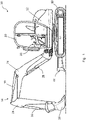
Figure 1 is a side view of a working vehicle according to an embodiment; -
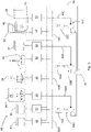
Figure 2 is a schematic of a hydraulic system of the working vehicle ofFigure 1 ; -
Figure 3 is a detailed schematic of a valve group of the hydraulic system ofFigure 2 ; -
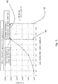
Figures 4 and5 are graphs representing characteristics of the proportional control valves ofFigures 2 and3 ; and -
Figure 6 is a flow chart for a method of controlling the hydraulic system ofFigures 2 and3 . - Referring to
Figure 1 , a working machine according to an embodiment is indicated at 10. The workingmachine 10 has achassis 12, a workingarm 14 attached to thechassis 12, and an implement 16 connected to a free end of the workingarm 14. In the illustrated embodiment, tracks 18 are provided to move the workingmachine 10. In alternative embodiments, wheels may be provided to move the workingmachine 10, instead of tracks 18. - The working
machine 10 includes acab 20 with a collection ofcontrols 22 for moving the workingarm 14, thetracks 18, or controlling other functions of the workingmachine 10. - The working
arm 14 includes aboom 24 pivotally attached to thechassis 12, adipper arm 26 pivotally attached to theboom 24, and an implement pivotally attached to thedipper arm 26. In the illustrated embodiment, the implement is abucket 16, which is used for soil-shifting or materials handling operations (e.g. trenching, grading, and loading) and/or materials handling (e.g. depositing aggregate in trenches, lifting materials and placing them on an elevated platform). In alternative embodiments, thebucket 16 may be removed and replaced with an alternative implement, such as a hydraulic hammer drill. - A
boom actuator 28 is provided to move theboom 24 in an ascending direction and a descending direction. The workingmachine 10 also includes adipper actuator 30, for pivoting thedipper arm 26 with respect to theboom 24, and abucket actuator 32, for pivoting thebucket 16 with respect to thedipper arm 26. - The working
machine 10 also includes, shown in schematic form inFigure 2 but not shown inFigure 1 : left andright track motors right tracks 18 forwards or backwards; aslew motor 38 for slewing thechassis 12 relative to thetracks 18; aswing actuator 40 for pivoting the workingarm 14 about a vertical axis relative to thechassis 12; adozer actuator 42 for actuating adozer blade 44; and a track extendactuator 46 for varying a length of thetracks 18. In some embodiments, the workingmachine 10 also includes one or more auxiliary hydraulic ports (not shown). - In the illustrated embodiment, the working
machine 10 is a slew excavator. In alternative embodiments, the workingmachine 10 may be any type of working machine including one or more hydraulically actuateddevices - The working
machine 10 also includes a hydraulic system for controlling the hydraulically actuateddevices Figures 2 to 6b. - In some embodiments, the working
vehicle 10 is an electric working vehicle, a fuel cell powered working vehicle (e.g. a working vehicle including a hydrogen fuel cell) or hybrid working vehicle of the kind having an electric source of power and an alternative source of power. The aspects of the disclosure described below have been found to significantly reduce hydraulic system losses by up to 50% compared to traditional independent metering hydraulic systems. This leads to a proportionate reduction in battery energy consumption when the hydraulic system is used on an electric workingvehicle 10, or a proportionate reduction in fuel consumption when the hydraulic system is used on a fuel cell powered working vehicle. - Referring now to
Figure 2 , a hydraulic system for the workingmachine 10 ofFigure 1 is indicated at 48. Thehydraulic system 48 is configured to supply hydraulic fluid to the hydraulically actuateddevices - As will be described in more detail below, the
hydraulic system 48 includes a plurality ofhydraulic pump assemblies tank 56 to one or more hydraulically-actuateddevices - In the illustrated embodiment, each
hydraulic pump assembly electric motor hydraulic system 48 is configured such that output of hydraulic fluid from eachhydraulic pump assembly electric motor hydraulic pump assemblies electric motors hydraulic pump assemblies vehicle 10 is an electric working vehicle or fuel cell powered working vehicle without an internal combustion engine to provide a mechanical drive for thehydraulic pump assemblies hybrid working vehicle 10 in which an internal combustion engine is not operated continuously. In alternative embodiments, thehydraulic pump assemblies hydraulic 50B, 50C.pump assembly 50A - As will be described in more detail below, a first group of the hydraulically actuated
devices vehicle 10, and are not actuated in order to carry out a second set of functions of the workingvehicle 10. The first group of hydraulically actuated devices includes theboom actuator 28,dipper actuator 30 andbucket actuator 32, and the first set of functions relates to movement of the workingarm 14. For example, the first set of functions includes excavating material with the workingarm 14; raising/lowering the workingarm 14; slewing the workingarm 14 about a vertical axis; and/or dumping excavated material from the working arm. - Referring to Table 1, an excavating function typically requires simultaneous actuation of the
boom actuator 28 at a relatively low pressure, actuation of thedipper actuator 30 at relatively high pressure, and actuation of thebucket actuator 32 at a medium pressure. A combined lifting and slewing function typically requires simultaneous actuation of theboom actuator 28 at a relatively high pressure, actuation of thedipper actuator 30 at relatively a low pressure, and actuation of theslew motor 38 at a relatively high pressure. A dumping function typically requires simultaneous actuation of theboom actuator 28 at high pressure, actuation of thedipper actuator 30 at relatively low pressure, and actuation of thebucket actuator 32 at a relatively low pressure. A return-to-trench function (i.e. after dumping an excavated load) typically requires simultaneous actuation of theboom actuator 28 anddipper actuator 30 at relatively low pressures, and actuation of theslew motor 38 at a medium pressure. - It will be understood that Table 1 only indicates typical pressure ranges, and that the actuation pressure of hydraulically actuated
devices Table 1: An overview of working machine functions and relative actuation pressures of associated hydraulically actuated devices Pump Assembly First (50A) Second (50B) Third (50C) Group 1 2 1 2 1 1 2 Hydraulically Actuated Device Boom (28) Dozer (42) Dipper (30) Left Track (34) Bucket (32) Slew (38) Right track (36) First set of functions Excavate LOW HIGH MEDIUM Lift and Slew HIGH LOW HIGH Dump HIGH LOW LOW Return to Trench LOW LOW MEDIUM Second set of functions Travel MEDIUM MEDIUM Levelling with Dozer LOW HIGH HIGH - As will also be described in more detail below, a second group of the hydraulically actuated
devices vehicle 10, and are not actuated in order to carry out the first set of functions of the workingvehicle 10. The second group of hydraulically actuated devices includes the left andright track motors chassis 12. For example, the second set of functions includes moving thechassis 12 forward or backwards in a straight line or curved path, or rotating thechassis 12 about a vertical axis (e.g. by rotating the left andright tracks 18 in opposite directions). - In the illustrated embodiment, the second group of hydraulically actuated devices also includes the
dozer actuator 42, and the second set of functions also includes levelling material with the dozer blade 44 (e.g. by moving thechassis 12 whilst simultaneously actuating the dozer blade 44). - Referring again to Table 1, a travelling function typically requires simultaneous actuation of the left and
right track motors dozer blade 44 typically requires simultaneous actuation of thedozer actuator 42 at a relatively low pressure, and actuation of the left andright track motors - It will be understand that the actuation pressure of the different actuators will vary depending on the design of the working
machine 10 andhydraulic system 48. For example, in some embodiments, relatively high pressures may be in the range of 100 to 250 Bar, relatively low pressures may be in the range of 0 to 50 Bar, and medium pressures may be between these ranges (i.e. in the range of 50 to 100 Bar). These example pressure ranges are for a small midi excavator. It will be understood that larger excavators or other working vehicles may operate at higher pressures. - As will be described in more detail below, the
hydraulic system 48 is arranged so that each of the hydraulically actuateddevices hydraulic pump assembly hydraulic system 48 is also arranged so that each of the hydraulically actuateddevices hydraulic pump assembly - However, it will be understood that such an architecture of the
hydraulic system 48 does not preclude simultaneous actuation of hydraulically actuated devices from the first and second groups. For example, it would still be possible to carry out a third set of non-typical functions in which thechassis 12 and workingarm 14 are moved simultaneously (e.g. when spreading excavated material by dumping with the workingarm 14 whilst moving thechassis 12 with the tracks 18). - In some embodiments, at least one of the
hydraulic pump assemblies device device - In the embodiment illustrated in
Figure 2 , thehydraulic system 48 includes threehydraulic pump assemblies tank 56 to two or more of the hydraulically actuateddevices hydraulic pump assemblies - However, in alternative embodiments, a dedicated hydraulic pump assembly is provided for each hydraulically actuated
device devices - In some embodiments, the
hydraulic system 48 is configured so that each of the sharedpump assemblies devices hydraulic system 48 is configured so that each of the sharedpump assemblies device - In the illustrated embodiment, the first
hydraulic pump assembly 50A supplies hydraulic fluid to theswing actuator 40,dipper actuator 30 and lefthand track motor 34; the secondhydraulic pump assembly 50B supplies hydraulic fluid to the righthand track motor 36,slew motor 38, andbucket actuator 32; and the thirdhydraulic pump assembly 50C supplies hydraulic fluid to thedozer actuator 42, track extendactuator 46 andboom actuator 28. - Such a hydraulic system configuration has been found to be a particularly efficient way of de-coupling those of hydraulically actuated
devices pump assembly devices hydraulic pump assembly - Left and
right track motors vehicle 10 in a straight line). Therefore, having the left andright track motors hydraulic pump assemblies vehicle 10. Similarly, aboom actuator 28,dipper arm actuator 30 andbucket actuator 32 are commonly used in tandem on a working vehicle 10 (e.g. when moving the working arm 14). Therefore, having theboom actuator 28,dipper actuator 30 andbucket actuator 32 supplied by differenthydraulic pump assemblies arm 14. - Conversely,
track motors arm actuators vehicle 10. For example, most commonly, a workingvehicle 10 moves with the workingarm 14 stationary, or the workingvehicle 10 is stationary whilst moving the workingarm 14. Therefore, supplying atrack motor arm actuator hydraulic pump assembly - In other words, those of hydraulically actuated
devices - Nevertheless, in operating conditions where a
track motor arm actuator Figure 3 ) to share the flow of hydraulic fluid from the shared pump assembly. - The
hydraulic system 48 also includes a plurality ofproportional control valves 52 which are each connected to a respective hydraulically-actuateddevice hydraulic system 48 is arranged so that hydraulic fluid exiting each of the hydraulically actuateddevices proportional control valve 52 before returning to thetank 56 via atank line 58. - In the illustrated embodiment, the
boom actuator 28,dipper actuator 30,bucket actuator 32, lefttrack motor 34,right track motor 36,slew motor 38 andswing actuator 40 are each connected to a dedicatedproportional control valve 52. In contrast, thedozer actuator 42 and track extendactuator 46 are connected to a commonproportional control valve 52 via a switchingvalve 53. The switchingvalve 53 has a first state which connects thedozer actuator 42 to the associatedproportional control valve 52, and a second state which connects the track extend actuator to the associatedproportional control valve 52. Such a switching arrangement is suitable when multiple hydraulically actuated devices will never be actuated simultaneously (e.g. actuation of thedozer blade 44 and extension of the tracks 18). The switching arrangement also reduces the required number ofproportional control valves 52 which are comparatively more expensive/complex than switching valves. However, it will be understood that wherever hydraulically actuated devices may need to be actuated simultaneously, they will be connected to independentproportional control valves 52. - In the illustrated embodiment, there are three
valve groups hydraulic pump assemblies proportional control valves 52 is part of one of thevalve groups valve groups proportional control valves 52 are shown schematically inFigure 2 . Specific details ofvalve groups 54A and theproportional control valves 52 are shown inFigure 3 , as discussed below. - The
hydraulic system 48 is configured to control a flow of hydraulic fluid supplied to each hydraulically actuateddevice hydraulic pump assemblies hydraulic system 48 is also configured to control a flow of hydraulic fluid exiting each of the hydraulically actuateddevice proportional control valves 52, as will be described in more detail below. - The
hydraulic system 48 is configured so that restriction of theproportional control valves 52 is controlled independently to the output from thehydraulic pump assemblies proportional control valves 52 being controlled independently to the output from thehydraulic pump assemblies device device hydraulic system 48. - Referring to
Figure 4 , each of theproportional control valves 52 is moveable within afirst opening range 60 between afirst opening position 62 and asecond opening position 64. Each of theproportional control valves 52 defines a first flow path through which a flow of hydraulic fluid from a respective hydraulically actuateddevice proportional control valves 52 are each configured so that a size of a restriction area of the first flow path decreases as theproportional control valve 52 is moved from thefirst opening position 62 to thesecond opening position 64 in order to increase a pressure of hydraulic fluid in an outlet side of the respective hydraulically actuateddevice - Referring to
Figure 5 , each of theproportional control valves 52 also defines a second flow path and thehydraulic system 48 is arranged such that theproportional control valves 52 each connect one of thehydraulic pump assemblies device hydraulic pump assemblies device proportional control valves 52 is arranged so that the second flow path is provided between one of the hydraulically actuateddevices hydraulic supply line hydraulic pump assembly - Each of the
proportional control valves 52 is configured so that a pressure differential across a restriction area of the second flow path is less than 10% of a maximum system pressure when the opening position of the proportional control valve is within said first opening range. For example, when the maximum system pressure is 230 bar, the pressure differential across the restriction area of the second flow path is less than 23 bar when the opening position of theproportional control valve 52 is within thefirst opening range 60. In some embodiments, the pressure differential across the restriction area of the second flow path is in the range of 0.5 bar to 4 bar (e.g. 1 bar) when theproportional control valve 52 is at thefirst opening position 62, and the pressure differential across the restriction area of the second flow path is in the range of 5 bar to 10 bar (e.g. 7 bar) when theproportional control valve 52 is at thesecond opening position 64. - It will be understood that the first opening ranges 60 of the
proportional control valves 52 differ depending on the output of hydraulic fluid from the associatedhydraulic pump assembly hydraulic pump assembly first opening range 60 may span from afirst opening position 62 of 100% of the maximum restriction area of the second flow path to asecond opening position 64 of 70% of the maximum restriction area of the second flow path. For the same hydraulic system at 50% of the maximum flow rate of the associatedhydraulic pump assembly first opening range 60 may span from afirst opening position 62 of 100% of the maximum restriction area of the second flow path to asecond opening position 64 of around 53% of the maximum restriction area of the second flow path. In alternative embodiments, thesecond opening position 64 may differ from those outlined above (e.g. greater or less than 70% of the maximum restriction area at 100% flow rate, and greater or less than 53% of the maximum restriction area at 50% flow rate). In any case, for a given hydraulic system configuration, thesecond opening position 64 which defines the bottom of thefirst opening range 60 will be lower when the flow rate of fluid supplied by the associatedhydraulic pump assembly - It will be understood that each of the
proportional control valves 52 may also be set to an opening position outside thefirst opening range 60, in order to further reduce the size of the restriction areas of the first and second flow paths to a fully closed position. In other words, theproportional control valves 52 are moveable within a second opening range between thesecond opening position 64 and a closed position. - Referring now to
Figure 3 , each of theproportional control valves 52 is a directional proportional control valve. In other words, each of theproportional control valves 52 has: a first state 68A for driving an associated hydraulically actuateddevice device device supply line Figures 4 and5 . - The
proportional control valves 52 being directional proportional control valves allows the hydraulically actuateddevices proportional control valve 52. This removes the need for additional control valves to change an actuation direction of the hydraulically actuateddevices - However, in alternative embodiments the
proportional control valves 52 are not directional control valves. For example, two separateproportional control valves 52 may be provided for each hydraulically actuateddevice proportional control valves 52 being configured to move the associated hydraulically actuateddevice - The
hydraulic system 48 also includes a plurality of pressure compensators 70. The number of pressure compensators 70 corresponds to the number ofproportional control valves 52 which are connected to a sharedpump assembly valve group 54A illustrated inFigure 3 , there are threeproportional control valves 52 connected to thehydraulic supply line 66A and three associated pressure compensators 70. In other words, each of the hydraulically actuateddevices pump assembly 50A is connected to the sharedpump assembly 50A via a respective pressure compensator 70. The pressure compensators 70 are arranged to restrict flow into their respective hydraulically actuateddevices pump assembly 50A between multiple hydraulically actuateddevices - In the illustrated embodiment, each of pressure compensators 70 is of the type commonly referred to as a "pre-compensator", whereby the pressure compensator 70 is provided between the
hydraulic pump assembly 50A and the associatedproportional control valve 52. A compensator opening area of each pressure compensator 70 is controlled by a pressure differential across the associated proportional control valve 52 (which is proportional to the flow passing across the restriction area of the second flow path of the proportional control valve 52) and is biased open by a spring 72. - When said pressure differential across the associated
proportional control valve 52 reaches a set value of the spring 72, a size of the compensator opening area is reduced to the point where it begins generate additional restriction to the flow of hydraulic fluid from thehydraulic pump assembly 50A to the associated hydraulically actuateddevice proportional control valve 52 increases further, the size of the compensator opening area is reduced further restrict the flow of hydraulic fluid from thehydraulic pump assembly 50A to the associated hydraulically actuateddevice proportional control valve 52, and thus how aggressively the flow of hydraulic fluid from thehydraulic pump assembly 50A to the associated hydraulically actuateddevice - In some embodiments, each
proportional control valve 52 is designed so that when its opening position is within thefirst opening range 60, the pressure differential across the restriction area of the second flow path of theproportional control valve 52 is less than the set value of the spring 72 of the associated pressure compensator 70. In this way, the compensator opening of the pressure compensator 70 is held fully open and has no restrictive effect when the opening position of the associatedproportional control valve 52 is within thefirst opening range 60. - In some embodiments, the set value of each spring is in the range of 2 to 15 bar or in the range of 5 to 10 bar (e.g. 7 bar).
- When only one of the hydraulically actuated
devices proportional control valve 52 will be within thefirst opening range 60. In this way, the associated pressure compensator 70 is fully open and a flow of hydraulic fluid into the hydraulically actuateddevice hydraulic pump assembly 50A. In other words, the pressure compensator 70 and restriction area of the second flow path of theproportional control valve 52 do not have a significant effect on the flow of hydraulic fluid entering the hydraulically actuateddevice - When multiple hydraulically actuated
devices proportional control valves 52 is set to a value outside the first opening range so that the associated pressure compensators 70 restrict a flow of hydraulic fluid to the hydraulically actuateddevices hydraulic pump assembly 50A between the hydraulically actuateddevices - In order to control the amount of compensation provided by the pressure compensators 70 so that certain hydraulically actuated
devices proportional control valve 52 associated with a higher priority hydraulically actuateddevice proportional control valve 52 before the associated compensator 70 begins to operate, giving priority to the associated hydraulically actuateddevice - In alternative embodiments, the pressure compensators 70 are of the type commonly known as "post-compensators". In such embodiments, the opening position of the pressure compensators 70 are each controlled by the load pressure of the associated hydraulically actuated
device proportional control valves 52 to achieve an equal pressure differential across allproportional control valves 52. In a post compensated system, the restriction areas of the first and second flow paths of theproportional control valves 52 would be designed as described above, but the requirement to design thefirst opening range 60 around the set value of the springs 72 is removed. Instead, theproportional control valves 52 would be designed so that a pressure differential across theproportional control valves 52 is set to a level that gives acceptable accuracy of the associated pressure compensator (e.g. 5 bar) when the proportional control valve is outside thefirst opening range 60. - The
hydraulic system 48 includes a control system 74 configured to control the flow rate and/or pressure of hydraulic fluid flowing through thehydraulic system 48. In the illustrated embodiment, the control system is configured to set the opening position of theproportional control valves 52 by varying a pressure of pilot fluid supplied from a pilot supply to first and second pressure ports of the proportional control valves 52 (e.g. by controlling solenoids 77 which alter the position of pilot valves 75, as illustrated inFigure 3 ). In alternative embodiments, theproportional control valves 52 are solenoid valves controlled directly by the control system 74, rather than via a pilot pressure. - The control system 74 is also configured to control the output of the
hydraulic pump assemblies electric motors Figure 2 ). - As will be described in more detail below, the control system 74 is configured to determine a loading condition of each hydraulically actuated
device - In some embodiments, the control system 74 is configured to determine such loading conditions via open-loop estimation. For example, the control system 74 may be configured to estimate the loading conditions of the hydraulically actuated
devices - In some embodiments, the control system 74 is configured to determine the loading conditions via feedback based on measurements indicative of the loading conditions.
- For example, the
hydraulic system 48 may include one or more pressure transducers for measuring a pressure of hydraulic fluid supplied by thehydraulic pump assemblies hydraulic pump assemblies - Alternatively, the
hydraulic system 48 may include one or more pressure transducers for measuring a pressure of hydraulic fluid entering or leaving each of the hydraulically actuated devices (e.g. a pair of pressure transducers for each of the hydraulically actuateddevices - Alternatively, the
hydraulic system 48 may include one or more force sensors for measuring a force acting on the hydraulically actuateddevices device - Alternatively, the
hydraulic system 48 may include one or more position sensors for measuring positions of the hydraulically actuateddevices e.g. boom 24,dipper arm 26, implement 16) and the control system 74 may be configured to determine the loading conditions as a function of the measured positions. - In some embodiments, the control system 74 may determine the loading conditions via an alternative means to those described above. In some embodiments, two or more of the means for determining the loading conditions described above may be combined to increase the accuracy of the loading condition determination.
- As will be described in more detail below, after determining the loading conditions the control system 74 is configured to adjust the restriction area of the respective
proportional control valves 52 in order to inhibit cavitation of the hydraulically actuateddevices - A method of controlling the
hydraulic system 48 outlined above will now be described in relation toFigure 6 . - In the illustrated embodiment, the control system 74 is configured to set an output command of the
hydraulic pump assemblies device more user inputs 22 of the workingvehicle 10, and set a flow command for eachhydraulic pump assembly device pump assemblies hydraulic system 48. - In the illustrated embodiment, the control system 74 is configured to set an opening position command for each
proportional control valve 52 to vary the restriction areas of the first and second flow paths of eachproportional control valve 52. - In the illustrated embodiment, the control system 74 is configured to do the following:
- monitor a loading condition of the hydraulically actuated
devices - compare each of said monitored loading conditions against a respective loading condition threshold;
- when one of said monitored loading conditions is less than its respective loading condition threshold, set an opening position command to decrease the restriction area of the first flow path of the respective
proportional control valve 52; and - when one of said monitored loading conditions is greater than its respective loading condition threshold, set an opening position command to increase the restriction area of the first flow path of the respective
proportional control valve 52. - In particular, the control system 74 is configured to do the following:
- monitor a pressure of hydraulic fluid supplied by each
hydraulic pump assembly - compare each of the monitored pressures against a respective pressure threshold (steps S22, S24, S26);
- when one of the monitored pressures is less than its respective pressure threshold, set an opening position command to decrease the restriction area of the first flow path of the respective proportional control valve 52 (step S32); or
- when one of said monitored pressures is greater than its respective pressure threshold, set an opening position command to increase the restriction area of the first flow path of the respective proportional control valve 52 (step S30).
- If the pump pressure is much greater than the target pressure (as calculated at step S22), the
proportional control valve 52 even at maximum opening position will still restrict valve area to a certain extent to maintain good back pressure on the hydraulically actuated device (step S28). - If the pump pressure matches the target pressure exactly, the opening position of the associated
proportional control valve 52 is held at its current position (step S34). - In some embodiments, the control system 74 is further configured to filter pressure signals indicative of the pressure of hydraulic fluid supplied by the or each
hydraulic pump assembly - In some embodiments, the control system 74 is further configured to set an opening position of each pressure compensator 70 to vary a restriction area of said pressure compensator 70 in order to control a share of flow of hydraulic fluid supplied by a shared
pump assembly devices - In some embodiments, the control system 74 is configured to determine a required opening position of each pressure compensator 70 based on the operating conditions of its associated
hydraulic pump assembly - When the calculations above indicate the
proportional control valve 52 needs to change opening position, theproportional control valve 52 is moved to the new target position at step S38. - The
hydraulic system 48 described above has been found to significantly reduce hydraulic system losses by up to 50% compared to traditional independent metering hydraulic systems. - A proportional control valve according to an embodiment will now be described in more detail. The
proportional control valve 52 includes a pump port for receiving hydraulic fluid from a hydraulic pump (e.g. a pump of thehydraulic pump assemblies hydraulic system 48 ofFigures 2 to 5 ); and a tank port for supplying hydraulic fluid to a tank (e.g. thetank 56 of the hydraulic system ofFigures 2 to 5 ). Theproportional control valve 52 also includes first and second actuator ports for supplying hydraulic fluid to a hydraulically actuated device or receiving hydraulic fluid from a hydraulically actuated device (e.g. one of the hydraulically actuateddevices hydraulic system 48 described above). - The
proportional control valve 52 defines a first flow path through which a flow of hydraulic fluid from the first or second actuator ports flows to the tank port. Theproportional control valve 52 also defines a second flow path through which a flow of hydraulic fluid from the pump port flows to the first or second actuator ports. - The
proportional control valve 52 is moveable within afirst opening range 60 between afirst opening position 62 and asecond opening position 64. It will be understood that the opening position of theproportional control valve 52 is continuously movable within the first opening range 60 (i.e. at thefirst opening position 62, thesecond opening position 64, or any opening position therebetween). - The
proportional control valve 52 is configured so that the size of a restriction area of the first flow path decreases as theproportional control valve 52 is moved from thefirst opening position 62 to thesecond opening position 64 in order to increase a pressure differential between the first or second actuator port and the tank port. - The
proportional control valve 52 is also configured so that a pressure differential across the restriction area of the second flow path is less than 10% of a maximum system pressure when the opening position of theproportional control valve 52 is within thefirst opening range 60. For example, when the maximum system pressure is 230 bar, the pressure differential across the restriction area of the second flow path is less than 23 bar when the opening position of theproportional control valve 52 is within thefirst opening range 60. In some embodiments, the pressure differential across the restriction area of the second flow path is in the range of 0.5 bar to 4 bar (e.g. 1 bar) when theproportional control valve 52 is at thefirst opening position 62, and the pressure differential across the restriction area of the second flow path is in the range of 5 bar to 10 bar (e.g. 7 bar) when theproportional control valve 52 is at thesecond opening position 64. - The
proportional control valve 52 is also moveable within a second opening range between the second opening position and a closed position, and theproportional control valve 52 is configured so that the size of the restriction areas of the first and second flow paths decreases as the proportional control valve is moved from the second opening position to the closed position in order to increase the pressure differentials across the first and second flow paths. - The aspects of the disclosure described above have been found to significantly reduce hydraulic system losses by up to 50% compared to traditional independent metering hydraulic systems. This leads to a proportionate reduction in battery energy consumption when the hydraulic system is used on an electric working vehicle, or a proportionate reduction in fuel consumption when the hydraulic system is used on a fuel cell powered working vehicle.
- It will be understood that the use of conventional proportional control valves 52 (i.e. directional spool valves) that are configured to operate as described above provides significant advantages over more complex/expensive "independent metering valves" with similar functionality.
- Although the diclosure has been described in relation to one or more embodiments, it will be appreciated that various changes or modifications can be made without departing from the scope defined by the appended claims.
- For example, in alternative embodiments, the pressure compensators 70 are omitted entirely. When flow sharing is required in such embodiments, the restriction areas of the first and second flow paths of the
proportional control valves 52 can be adjusted directly to control the sharing of flow from the respective sharedpump assembly devices device proportional control valves 52 are then actuated by the control system 74 so that the combined restriction of the respective first and second flow paths of theproportional control valves 52 creates the necessary pressure differential for each hydraulically actuateddevice - It will be understood that in such an uncompensated hydraulic system embodiment, the control system 74 follows similar steps to those shown in the flow chart of
Figure 6 , but that step S36 is replaced by the flow sharing strategy outlined above. - In further alternative embodiments, the
slew motor 38 for slewing thechassis 12 relative to thetracks 18 is an electric motor rather than a hydraulic motor. An overview of the working machine functions and associated pressures for such an embodiment is outlined in Table 2 below. In contrast to Table 1 above, because thehydraulic slew motor 38 has been replaced with an electric slew motor the thirdhydraulic pump assembly 50C only has one hydraulically actuated device assigned to the "Group 1" functions (the bucket actuator 32). In this way, when only "Group 1" functions are selected, no flow sharing would take place, which further increases the efficiency of the hydraulic system.Table 2: An overview of working machine functions and relative actuation pressures of associated hydraulically actuated devices Pump Assembly First (50A) Second (50B) Third (50C) Group 1 2 1 2 1 2 Hydraulically Actuated Device Boom (28) Dozer (42) Dipper (30) Left Track (34) Bucket (32) Right track (36) First set of functions Excavate LOW HIGH MEDIUM Lift and Slew HIGH LOW Dump HIGH LOW LOW Return to Trench LOW LOW Second set of functions Travel MEDIUM MEDIUM Levelling with Dozer LOW HIGH HIGH - It should also be noted that whilst the appended claims set out particular combinations of features described above, the scope of the present disclosure is not limited to the particular combinations hereafter claimed, but instead extends to encompass each feature herein disclosed in isolation, as well as any combination of features herein disclosed.
Claims (16)
- A hydraulic system for a working vehicle, the hydraulic system comprising:a hydraulically actuated device;a hydraulic pump assembly for supplying a variable output of hydraulic fluid to the hydraulically actuated device; anda proportional control valve, wherein the hydraulic system is arranged such that hydraulic fluid exiting the hydraulically actuated device flows through a restriction of the proportional control valve; andwherein the hydraulic system is configured to control a flow of hydraulic fluid supplied to the hydraulically actuated device by varying the output of hydraulic fluid from the hydraulic pump assembly, and to control a flow of hydraulic fluid exiting the hydraulically actuated device via adjusting a restriction area of the proportional control valve.
- A hydraulic system according to claim 1, wherein the hydraulic system is configured so that restriction of the proportional control valve is controlled independently to the output from the hydraulic pump assembly such that pressure of an inlet side of the hydraulically actuated device is controlled independently of the pressure of an outlet side of the hydraulically actuated device.
- A hydraulic system according to claim 1 or 2, wherein the proportional control valve is moveable within a first opening range between a first opening position and a second opening position, wherein the proportional control valve defines a first flow path through which a flow of hydraulic fluid from the hydraulically actuated device flows, and wherein the proportional control valve is configured so that a size of a restriction area of the first flow path decreases as the proportional control valve is moved from the first opening position to the second opening position in order to increase a pressure of hydraulic fluid in an outlet side of the hydraulically actuated device.
- A hydraulic system according to claim 3, wherein the proportional control valve defines a second flow path, and wherein the hydraulic system is arranged such that the proportional control valve connects the hydraulic pump assembly to the hydraulically actuated device so that hydraulic fluid supplied by the hydraulic pump assembly to the hydraulically actuated device flows through the second flow path, wherein the proportional control valve is configured so that a pressure differential across a restriction area of the second flow path is less than 10% of a maximum system pressure when the opening position of the proportional control valve is within said first opening range; optionally, wherein the proportional control valve is a directional proportional control valve.
- A hydraulic system according to any preceding claim, further comprising a plurality of hydraulically actuated devices and a corresponding plurality of proportional control valves, wherein the hydraulic system is arranged so that hydraulic fluid exiting each of the hydraulically actuated devices flows through a restriction of a respective proportional control valve; optionally, further comprising a plurality of hydraulic pump assemblies for supplying a variable output of hydraulic fluid to the hydraulically actuated devices.
- A hydraulic system according to claim 5, wherein the number of hydraulic pump assemblies corresponds to the number of hydraulically actuated devices, wherein the hydraulic system is configured to control a flow of hydraulic fluid entering each hydraulically actuated device via varying the output of hydraulic fluid from a respective hydraulic pump assembly, and to control a flow of hydraulic fluid exiting each hydraulically actuated device via varying a restriction of a respective proportional control valve.
- A hydraulic system according to claim 5, wherein the number of hydraulic pump assemblies is less than the number of hydraulically actuated devices, and wherein one or more of the hydraulic pump assemblies is a shared pump assembly for supplying hydraulic fluid to two or more hydraulically actuated devices; optionally, wherein the hydraulic system is configured so that the shared pump assembly supplies hydraulic fluid to two or more hydraulically actuated devices simultaneously; optionally, wherein each of the hydraulically actuated devices supplied by the shared pump assembly is connected to the shared pump assembly via a respective pressure compensator, and wherein the pressure compensators are arranged to restrict flow into their respective hydraulically actuated devices to control a share of the flow of hydraulic fluid supplied by the shared pump assembly between multiple hydraulically actuated devices; optionally, wherein each pressure compensator is biased open by a spring, wherein a compensator opening area of each pressure compensator is controlled by a pressure differential across a restriction area of the second flow path of a respective proportional control valve, and wherein the proportional control valve is configured so that said pressure differential across the restriction area of said second flow path is less than a set value of the pressure compensator spring when the opening position of the proportional control valve is within the first opening range and is greater than said set value of the pressure compensator spring when the opening position of the proportional control valve is outside the first opening range.
- A hydraulic system according to any of claims 5 to 7, wherein the hydraulic system comprises a plurality of hydraulic pump assemblies for supplying a variable output of hydraulic fluid to the hydraulically actuated devices, wherein:the plurality of hydraulically-actuated devices comprise a left-hand track motor for actuating a left-hand track of the working vehicle and a right-hand track motor for actuating a right-hand track of the working vehicle, and wherein the left-hand track motor is supplied with hydraulic fluid from a first of the hydraulic pump assemblies and the right-hand track motor is supplied with hydraulic fluid from a second of the hydraulic pump assemblies, optionally, wherein the first of the hydraulic pump assemblies is a shared pump assembly for supplying hydraulic fluid to the left-hand track motor and a first working arm actuator for actuating a working arm of the working vehicle, and/or wherein the second of the hydraulic pump assemblies is a shared pump assembly for supplying hydraulic fluid to the right-hand track motor and a second working arm actuator for actuating a working arm of the working vehicle; and/orthe plurality of hydraulically-actuated devices comprise a boom actuator for raising or lowering a working arm of the working vehicle and a dipper arm actuator for pivoting a dipper arm of the working vehicle relative to a boom of the working vehicle, and wherein the boom actuator is supplied with hydraulic fluid from one of the hydraulic pump assemblies and the dipper arm actuator is supplied with hydraulic fluid from a different one of the hydraulic pump assemblies.
- A hydraulic system according to any preceding claim, wherein the or each hydraulic pump assembly is driven by a respective electric motor, and wherein the hydraulic system is configured such that output of hydraulic fluid from the or each hydraulic pump assembly is varied by adjusting a rotation speed of said electric motor.
- A hydraulic system according to any preceding claim, further comprising a control system configured to control a flow rate and/or pressure of hydraulic fluid flowing through the hydraulic system; optionally, wherein the control system is configured to set an output command of the or each hydraulic pump assembly, optionally, wherein the control system is configured to calculate a target velocity for the or each hydraulically actuated device based on one or more user inputs of the working vehicle, and set a flow command of the or each hydraulic pump assembly based on the or each target velocity.
- A hydraulic system according to claim 10, wherein the control system is configured to set an opening position command of the or each proportional control valve to vary the restriction of the proportional control valve; optionally, wherein the control system is configured to determine a loading condition of the or each hydraulically actuated device and to adjust the restriction area of the respective proportional control valve in order to inhibit cavitation of said hydraulically actuated device;optionally, wherein the control system is configured to estimate the loading condition of the or each hydraulically actuated device through use of a look-up table of typical loading conditions;optionally, wherein the control system is configured to estimate the loading condition of the or each hydraulically actuated device based on a position of one or more user inputs, such as joysticks, levers, pedals or the like;optionally, wherein the control system is configured to determine the loading condition of the or each hydraulically actuated device as a function of a measured pressure of hydraulic fluid supplied by the or each hydraulic pump assembly;optionally, wherein the control system is configured to determine the loading condition of the or each hydraulically actuated device based on a measured pressure at an outlet port of the or each hydraulically actuated device and/or a measured pressure at an inlet port of the or each hydraulically actuated device;optionally, wherein the control system is configured to determine the loading condition of the or each hydraulically actuated device as a function of a measured force acting on the or each hydraulically actuated device; and/oroptionally, wherein the control system is configured to determine the loading condition of the or each hydraulically actuated device as a function of a measured position of the or each hydraulically actuated device or a measured position of one or more elements of said working machine that are actuated by the hydraulically actuated device(s).
- A hydraulic system according to claim 11, wherein the control system is configured to:monitor a loading condition of the or each hydraulically actuated device;compare the or each of said monitored loading conditions against a respective loading condition threshold;when one of said monitored loading conditions is less than its respective loading condition threshold, set an opening position command to decrease a restriction area of the first flow path of the respective proportional control valve; andwhen one of said monitored loading conditions is greater than its respective loading condition threshold, set an opening position command to increase the restriction area of the first flow path of the respective proportional control valve;optionally, wherein the control system is configured to:monitor a pressure of hydraulic fluid supplied by the or each hydraulic pump assembly;compare the or each of said monitored pressures against a respective pressure threshold;when one of said monitored pressures is less than its respective pressure threshold, set an opening position command to decrease a restriction area of the first flow path of the respective proportional control valve; orwhen one of said monitored pressures is greater than its respective pressure threshold, set an opening position command to increase the restriction area of the first flow path of the respective proportional control valve;optionally, wherein the control system is further configured to filter pressure signals indicative of the pressure of hydraulic fluid supplied by the or each hydraulic pump assembly.
- A hydraulic system according to any of claims 10 to 12, further comprising a plurality of hydraulically actuated devices and a plurality of hydraulic pump assemblies, wherein:the number of hydraulic pump assemblies is less than the number of hydraulically actuated devices;one or more of the hydraulic pump assemblies is a shared pump assembly for supplying hydraulic fluid to two or more hydraulically actuated devices;wherein each of the hydraulically actuated devices supplied by the shared pump assembly is connected to the shared pump assembly via a respective proportional control valve and the control system is configured to set an opening position of each proportional control valve to vary a restriction area of said proportional control valve in order to control a share of the flow of hydraulic fluid supplied by the shared pump assembly between multiple hydraulically actuated devices, optionally, wherein the control system is configured to determine a required opening position of each proportional control valve based on the operating conditions of its respective hydraulic pump assembly and hydraulically actuated device; orwherein each of the hydraulically actuated devices supplied by the shared pump assembly is connected to the shared pump assembly via a respective pressure compensator and the control system is configured to set an opening position of each pressure compensator to vary a restriction area of said pressure compensator in order to control a share of the flow of hydraulic fluid supplied by the shared pump assembly between multiple hydraulically actuated devices, optionally, wherein the control system is configured to determine a required opening position of each pressure compensator based on the operating conditions of its respective hydraulic pump assembly and proportional control valve.
- A hydraulic system for a working vehicle, the hydraulic system comprising:a first group of hydraulically actuated devices which are actuated simultaneously to carry out a first set of functions of said working vehicle and which are not actuated in order to carry out a second set of functions of said working vehicle;a second group of hydraulically actuated devices which are actuated simultaneously to carry out the second set of functions of said working vehicle and which are not actuated in order to carry out the first set of functions of said working vehicle; andtwo or more hydraulic pump assemblies for supplying hydraulic fluid to the hydraulically actuated devices of the first and second groups;wherein the hydraulic system is arranged so that each hydraulically actuated devices of the first group is supplied by a different one of the hydraulic pump assemblies;wherein the hydraulic system is arranged so that each hydraulically actuated devices of the second group is supplied by a different one of the hydraulic pump assemblies; andwherein at least one of the hydraulic pump assemblies is arranged for supplying hydraulic fluid to both a hydraulically actuated device of the first group and a hydraulically actuated device of the second group;optionally, wherein one or more hydraulically actuated devices of the first group and one or more hydraulically actuated devices of the second group are actuated simultaneously to carry out a third set of functions of said working vehicle; optionally, wherein the third set of functions relate to simultaneous movement of a chassis of said working vehicle and movement of a working arm of said working vehicle (e.g. spreading excavated material by dumping with a working arm whilst moving a chassis of the working vehicle).
- A hydraulic system according to claim 14, wherein the first set of functions relates to movement of a working arm of said working vehicle, and wherein the first group of hydraulically actuated devices comprises two or more actuators associated with movement of said working arm; optionally, wherein the first group of hydraulically actuated devices comprises at least two of: a boom actuator, a dipper arm actuator and/or an implement actuator; optionally, wherein the first set of functions comprises: excavating material with a working arm; raising/lowering a working arm; slewing the working arm about a vertical axis; and/or dumping excavated material from the working arm; and/or
wherein the second set of functions relates to movement of a chassis of said working vehicle, and wherein the second group of hydraulically actuated devices comprises two or more actuators associated with movement of the chassis; optionally, wherein the second group of hydraulically actuated devices comprises a left track motor and a right track motor; optionally, wherein the second group of hydraulically actuated devices comprises a dozer actuator; optionally, wherein the second set of functions comprises: moving said chassis (e.g. forward or backwards in a straight line or curved path, or rotating about a vertical axis); and/or levelling material with a dozer blade (e.g. moving said chassis whilst simultaneously actuating a dozer blade). - A hydraulic system according to claim 14 or 15,wherein the first group of hydraulically actuated devices comprises: a boom actuator for raising/lowering a boom of a working arm; a dipper actuator for pivoting a dipper arm of a working arm with respect to said boom; and an implement actuator for pivoting, extending or otherwise actuating an implement coupled to said dipper arm,wherein the second group of hydraulically actuated devices comprises a left track motor, a right track motor,wherein the left track motor and one of the boom actuator, dipper actuator and implement actuator are driven by a first of the hydraulic pump assemblies,wherein the right track motor and another of the boom actuator, dipper actuator and implement actuator are driven by a second of the hydraulic pump assemblies, andwherein the other of the boom actuator, dipper actuator and implement actuator is driven by a third of the hydraulic pump assemblies, optionally, wherein the second group of hydraulically actuated devices further comprises a dozer actuator for actuating a dozer blade of said working vehicle, wherein the dozer actuator is driven by the third of the hydraulic pump assemblies, and/or optionally wherein:the dipper actuator and one of the left or right track motors are driven by the first hydraulic pump assembly,the implement actuator, the other of the left or right track motors and, optionally, a slew motor are driven by the second hydraulic pump assembly, andthe boom actuator and dozer actuator are driven by the third hydraulic pump assembly.
Priority Applications (2)
| Application Number | Priority Date | Filing Date | Title |
|---|---|---|---|
| EP25210301.5A EP4660464A3 (en) | 2021-03-08 | 2022-03-02 | Hydraulic system |
| EP23217704.8A EP4317707B1 (en) | 2021-03-08 | 2022-03-02 | Hydraulic system for a construction machine |
Applications Claiming Priority (1)
| Application Number | Priority Date | Filing Date | Title |
|---|---|---|---|
| GB2103208.1A GB2604608B (en) | 2021-03-08 | 2021-03-08 | Hydraulic system |
Related Child Applications (2)
| Application Number | Title | Priority Date | Filing Date |
|---|---|---|---|
| EP23217704.8A Division EP4317707B1 (en) | 2021-03-08 | 2022-03-02 | Hydraulic system for a construction machine |
| EP25210301.5A Division EP4660464A3 (en) | 2021-03-08 | 2022-03-02 | Hydraulic system |
Publications (2)
| Publication Number | Publication Date |
|---|---|
| EP4056765A1 true EP4056765A1 (en) | 2022-09-14 |
| EP4056765B1 EP4056765B1 (en) | 2024-01-03 |
Family
ID=75472484
Family Applications (3)
| Application Number | Title | Priority Date | Filing Date |
|---|---|---|---|
| EP25210301.5A Pending EP4660464A3 (en) | 2021-03-08 | 2022-03-02 | Hydraulic system |
| EP22275023.4A Active EP4056765B1 (en) | 2021-03-08 | 2022-03-02 | Hydraulic system for a construction machine |
| EP23217704.8A Active EP4317707B1 (en) | 2021-03-08 | 2022-03-02 | Hydraulic system for a construction machine |
Family Applications Before (1)
| Application Number | Title | Priority Date | Filing Date |
|---|---|---|---|
| EP25210301.5A Pending EP4660464A3 (en) | 2021-03-08 | 2022-03-02 | Hydraulic system |
Family Applications After (1)
| Application Number | Title | Priority Date | Filing Date |
|---|---|---|---|
| EP23217704.8A Active EP4317707B1 (en) | 2021-03-08 | 2022-03-02 | Hydraulic system for a construction machine |
Country Status (5)
| Country | Link |
|---|---|
| US (1) | US12281461B2 (en) |
| EP (3) | EP4660464A3 (en) |
| CN (1) | CN115045874A (en) |
| BR (1) | BR102022004280A2 (en) |
| GB (1) | GB2604608B (en) |
Families Citing this family (2)
| Publication number | Priority date | Publication date | Assignee | Title |
|---|---|---|---|---|
| CN115325218A (en) * | 2022-09-16 | 2022-11-11 | 湖州生力液压有限公司 | Monostable type flashlight integrated control valve |
| CN115614342B (en) * | 2022-09-26 | 2025-08-05 | 江苏国瑞液压机械有限公司 | A multi-dimensional discrete micro-high-speed switching valve and its working method |
Citations (12)
| Publication number | Priority date | Publication date | Assignee | Title |
|---|---|---|---|---|
| EP0533958A1 (en) * | 1991-04-12 | 1993-03-31 | Hitachi Construction Machinery Co., Ltd. | Hydraulic driving system in construction machine |
| EP1750017A1 (en) * | 2005-08-02 | 2007-02-07 | Volvo Construction Equipment Holding Sweden AB | Traveling system for heavy construction equipment |
| EP2541072A2 (en) * | 2011-07-01 | 2013-01-02 | Robert Bosch Gmbh | Control assembly and method for controlling multiple hydraulic consumers |
| WO2014036232A1 (en) * | 2012-08-31 | 2014-03-06 | Caterpillar Inc. | Hydraulic control system having over-pressure protection |
| US20140116038A1 (en) * | 2012-11-01 | 2014-05-01 | Husco International, Inc. | Hydraulic system with open loop electrohydraulic pressure compensation |
| US20180051720A1 (en) * | 2015-09-29 | 2018-02-22 | Hitachi Construction Machinery Co., Ltd. | Hydraulic Fluid Energy Regeneration Apparatus of Work Machine |
| US20180051444A1 (en) * | 2015-06-01 | 2018-02-22 | Hitachi Construction Machinery Co., Ltd. | Hydraulic Control System of Construction Machine |
| US20180106278A1 (en) * | 2016-03-10 | 2018-04-19 | Hitachi Construction Machinery Co., Ltd. | Construction machine |
| EP3489424A1 (en) * | 2017-03-13 | 2019-05-29 | Hitachi Construction Machinery Tierra Co., Ltd. | Hydraulic drive device for electric hydraulic work machine |
| US20190186105A1 (en) * | 2017-05-09 | 2019-06-20 | Hitachi Construction Machinery Co., Ltd. | Work Machine |
| JP2019199726A (en) * | 2018-05-15 | 2019-11-21 | 川崎重工業株式会社 | Driving system of hydraulic shovel |
| EP3674563A1 (en) * | 2018-09-05 | 2020-07-01 | Hitachi Construction Machinery Tierra Co., Ltd. | Hydraulic drive device of electric-powered hydraulic operating machine |
Family Cites Families (15)
| Publication number | Priority date | Publication date | Assignee | Title |
|---|---|---|---|---|
| DE4120665A1 (en) | 1991-06-22 | 1992-12-24 | Teves Gmbh Alfred | ELECTRICALLY DRIVEN HYDRAULIC PUMP |
| DE19612582A1 (en) | 1996-03-29 | 1997-10-02 | Miag Fahrzeugbau Gmbh | Drive unit for vehicle e.g forklift truck |
| EP0857871B1 (en) | 1997-02-05 | 2001-11-07 | Hoerbiger Hydraulik GmbH | Motor pump unit |
| US6918248B2 (en) * | 2001-04-17 | 2005-07-19 | Caterpillar Inc | Independent metering valve assembly for multiple hydraulic load functions |
| JP2008032175A (en) * | 2006-07-31 | 2008-02-14 | Shin Caterpillar Mitsubishi Ltd | Fluid-pressure circuit |
| JP5351813B2 (en) * | 2010-03-31 | 2013-11-27 | 株式会社クボタ | Working vehicle hydraulic system |
| WO2014109131A1 (en) * | 2013-01-08 | 2014-07-17 | 日立建機株式会社 | Hydraulic system for work machine |
| US9915192B2 (en) * | 2014-08-04 | 2018-03-13 | Jeffrey J. Buschur | Power conversion device |
| ITUB20153995A1 (en) * | 2015-09-29 | 2017-03-29 | Cnh Ind Italia Spa | Hydraulic circuit for use on a CVT vehicle. |
| DE102015119055B4 (en) | 2015-11-06 | 2019-05-09 | Knorr-Bremse Systeme für Schienenfahrzeuge GmbH | Hydro unit |
| US20200230115A1 (en) * | 2017-07-24 | 2020-07-23 | University Of Cincinnati | Methods of treating influenza-associated viral pneumonia |
| KR20190032287A (en) * | 2017-08-31 | 2019-03-27 | 가부시키가이샤 고마쓰 세이사쿠쇼 | Control system of working machine and control method of working machine |
| EP3708718B1 (en) * | 2017-11-10 | 2024-06-12 | Sumitomo (S.H.I.) Construction Machinery Co., Ltd. | Excavator |
| JP6974217B2 (en) * | 2018-02-28 | 2021-12-01 | 株式会社小松製作所 | Construction management equipment |
| JP7431604B2 (en) * | 2020-02-13 | 2024-02-15 | キャタピラー エス エー アール エル | Valve calibration system and method |
-
2021
- 2021-03-08 GB GB2103208.1A patent/GB2604608B/en active Active
-
2022
- 2022-03-02 EP EP25210301.5A patent/EP4660464A3/en active Pending
- 2022-03-02 EP EP22275023.4A patent/EP4056765B1/en active Active
- 2022-03-02 EP EP23217704.8A patent/EP4317707B1/en active Active
- 2022-03-08 BR BR102022004280-2A patent/BR102022004280A2/en unknown
- 2022-03-08 CN CN202210220582.9A patent/CN115045874A/en active Pending
- 2022-03-08 US US17/689,975 patent/US12281461B2/en active Active
Patent Citations (12)
| Publication number | Priority date | Publication date | Assignee | Title |
|---|---|---|---|---|
| EP0533958A1 (en) * | 1991-04-12 | 1993-03-31 | Hitachi Construction Machinery Co., Ltd. | Hydraulic driving system in construction machine |
| EP1750017A1 (en) * | 2005-08-02 | 2007-02-07 | Volvo Construction Equipment Holding Sweden AB | Traveling system for heavy construction equipment |
| EP2541072A2 (en) * | 2011-07-01 | 2013-01-02 | Robert Bosch Gmbh | Control assembly and method for controlling multiple hydraulic consumers |
| WO2014036232A1 (en) * | 2012-08-31 | 2014-03-06 | Caterpillar Inc. | Hydraulic control system having over-pressure protection |
| US20140116038A1 (en) * | 2012-11-01 | 2014-05-01 | Husco International, Inc. | Hydraulic system with open loop electrohydraulic pressure compensation |
| US20180051444A1 (en) * | 2015-06-01 | 2018-02-22 | Hitachi Construction Machinery Co., Ltd. | Hydraulic Control System of Construction Machine |
| US20180051720A1 (en) * | 2015-09-29 | 2018-02-22 | Hitachi Construction Machinery Co., Ltd. | Hydraulic Fluid Energy Regeneration Apparatus of Work Machine |
| US20180106278A1 (en) * | 2016-03-10 | 2018-04-19 | Hitachi Construction Machinery Co., Ltd. | Construction machine |
| EP3489424A1 (en) * | 2017-03-13 | 2019-05-29 | Hitachi Construction Machinery Tierra Co., Ltd. | Hydraulic drive device for electric hydraulic work machine |
| US20190186105A1 (en) * | 2017-05-09 | 2019-06-20 | Hitachi Construction Machinery Co., Ltd. | Work Machine |
| JP2019199726A (en) * | 2018-05-15 | 2019-11-21 | 川崎重工業株式会社 | Driving system of hydraulic shovel |
| EP3674563A1 (en) * | 2018-09-05 | 2020-07-01 | Hitachi Construction Machinery Tierra Co., Ltd. | Hydraulic drive device of electric-powered hydraulic operating machine |
Also Published As
| Publication number | Publication date |
|---|---|
| EP4660464A2 (en) | 2025-12-10 |
| EP4317707A2 (en) | 2024-02-07 |
| GB2604608B (en) | 2025-04-23 |
| EP4660464A3 (en) | 2026-03-18 |
| EP4317707A3 (en) | 2024-05-01 |
| GB202103208D0 (en) | 2021-04-21 |
| CN115045874A (en) | 2022-09-13 |
| BR102022004280A2 (en) | 2022-10-11 |
| EP4056765B1 (en) | 2024-01-03 |
| US20220282454A1 (en) | 2022-09-08 |
| GB2604608A (en) | 2022-09-14 |
| EP4317707B1 (en) | 2025-10-29 |
| US12281461B2 (en) | 2025-04-22 |
Similar Documents
| Publication | Publication Date | Title |
|---|---|---|
| CN106795707B (en) | Excavator | |
| JP4454131B2 (en) | Construction machine hydraulic regeneration device and construction machine | |
| US9341198B2 (en) | Hydraulic drive device for working machine | |
| EP2351937B1 (en) | Hydraulic control system in working machine | |
| US9074346B2 (en) | Work machine and control method for work machines | |
| EP0503073A1 (en) | Hydraulic control system in construction machine | |
| WO2019049435A1 (en) | Construction machine | |
| US11542963B2 (en) | Hydraulic drive device for traveling work machine | |
| WO2017056199A1 (en) | Construction machine | |
| US12241229B2 (en) | Shovel | |
| KR101865285B1 (en) | Control system, work machine, and control method | |
| EP4317707B1 (en) | Hydraulic system for a construction machine | |
| CN114555957A (en) | Regeneration device, hydraulic drive system provided with regeneration device, and control device for hydraulic drive system | |
| CN114245838B (en) | Hydraulic drives for construction machinery | |
| JP2020139574A (en) | Construction machine | |
| JP6615137B2 (en) | Hydraulic drive unit for construction machinery | |
| JP2004197825A (en) | Hydraulic drive | |
| CN112567141B (en) | construction machinery | |
| JP4702894B2 (en) | Hydraulic control system for hydraulic excavator | |
| JP2022170467A (en) | Work machine | |
| EP3608548B1 (en) | Construction machine | |
| EP4686790A1 (en) | Control system | |
| JP2013249900A (en) | Hydraulic drive circuit | |
| JP2025034785A (en) | Excavator | |
| JP2025144462A (en) | Work machinery |
Legal Events
| Date | Code | Title | Description |
|---|---|---|---|
| PUAI | Public reference made under article 153(3) epc to a published international application that has entered the european phase |
Free format text: ORIGINAL CODE: 0009012 |
|
| STAA | Information on the status of an ep patent application or granted ep patent |
Free format text: STATUS: THE APPLICATION HAS BEEN PUBLISHED |
|
| AK | Designated contracting states |
Kind code of ref document: A1 Designated state(s): AL AT BE BG CH CY CZ DE DK EE ES FI FR GB GR HR HU IE IS IT LI LT LU LV MC MK MT NL NO PL PT RO RS SE SI SK SM TR |
|
| STAA | Information on the status of an ep patent application or granted ep patent |
Free format text: STATUS: REQUEST FOR EXAMINATION WAS MADE |
|
| STAA | Information on the status of an ep patent application or granted ep patent |
Free format text: STATUS: EXAMINATION IS IN PROGRESS |
|
| 17P | Request for examination filed |
Effective date: 20230313 |
|
| RBV | Designated contracting states (corrected) |
Designated state(s): AL AT BE BG CH CY CZ DE DK EE ES FI FR GB GR HR HU IE IS IT LI LT LU LV MC MK MT NL NO PL PT RO RS SE SI SK SM TR |
|
| 17Q | First examination report despatched |
Effective date: 20230405 |
|
| GRAP | Despatch of communication of intention to grant a patent |
Free format text: ORIGINAL CODE: EPIDOSNIGR1 |
|
| STAA | Information on the status of an ep patent application or granted ep patent |
Free format text: STATUS: GRANT OF PATENT IS INTENDED |
|
| RIC1 | Information provided on ipc code assigned before grant |
Ipc: F15B 11/16 20060101ALI20230415BHEP Ipc: E02F 3/32 20060101ALI20230415BHEP Ipc: E02F 9/20 20060101ALI20230415BHEP Ipc: E02F 3/96 20060101ALI20230415BHEP Ipc: B66F 11/04 20060101ALI20230415BHEP Ipc: F15B 21/08 20060101ALI20230415BHEP Ipc: F15B 11/044 20060101ALI20230415BHEP Ipc: F15B 11/042 20060101ALI20230415BHEP Ipc: E02F 9/22 20060101AFI20230415BHEP |
|
| INTG | Intention to grant announced |
Effective date: 20230523 |
|
| GRAJ | Information related to disapproval of communication of intention to grant by the applicant or resumption of examination proceedings by the epo deleted |
Free format text: ORIGINAL CODE: EPIDOSDIGR1 |
|
| STAA | Information on the status of an ep patent application or granted ep patent |
Free format text: STATUS: EXAMINATION IS IN PROGRESS |
|
| GRAP | Despatch of communication of intention to grant a patent |
Free format text: ORIGINAL CODE: EPIDOSNIGR1 |
|
| STAA | Information on the status of an ep patent application or granted ep patent |
Free format text: STATUS: GRANT OF PATENT IS INTENDED |
|
| INTC | Intention to grant announced (deleted) | ||
| INTG | Intention to grant announced |
Effective date: 20230925 |
|
| GRAS | Grant fee paid |
Free format text: ORIGINAL CODE: EPIDOSNIGR3 |
|
| GRAA | (expected) grant |
Free format text: ORIGINAL CODE: 0009210 |
|
| STAA | Information on the status of an ep patent application or granted ep patent |
Free format text: STATUS: THE PATENT HAS BEEN GRANTED |
|
| P01 | Opt-out of the competence of the unified patent court (upc) registered |
Effective date: 20231030 |
|
| AK | Designated contracting states |
Kind code of ref document: B1 Designated state(s): AL AT BE BG CH CY CZ DE DK EE ES FI FR GB GR HR HU IE IS IT LI LT LU LV MC MK MT NL NO PL PT RO RS SE SI SK SM TR |
|
| REG | Reference to a national code |
Ref country code: GB Ref legal event code: FG4D |
|
| REG | Reference to a national code |
Ref country code: CH Ref legal event code: EP |
|
| REG | Reference to a national code |
Ref country code: DE Ref legal event code: R096 Ref document number: 602022001554 Country of ref document: DE |
|
| REG | Reference to a national code |
Ref country code: IE Ref legal event code: FG4D |
|
| REG | Reference to a national code |
Ref country code: SE Ref legal event code: TRGR |
|
| REG | Reference to a national code |
Ref country code: LT Ref legal event code: MG9D |
|
| PG25 | Lapsed in a contracting state [announced via postgrant information from national office to epo] |
Ref country code: ES Free format text: LAPSE BECAUSE OF FAILURE TO SUBMIT A TRANSLATION OF THE DESCRIPTION OR TO PAY THE FEE WITHIN THE PRESCRIBED TIME-LIMIT Effective date: 20240103 |
|
| PG25 | Lapsed in a contracting state [announced via postgrant information from national office to epo] |
Ref country code: ES Free format text: LAPSE BECAUSE OF FAILURE TO SUBMIT A TRANSLATION OF THE DESCRIPTION OR TO PAY THE FEE WITHIN THE PRESCRIBED TIME-LIMIT Effective date: 20240103 |
|
| REG | Reference to a national code |
Ref country code: NL Ref legal event code: MP Effective date: 20240103 |
|
| REG | Reference to a national code |
Ref country code: AT Ref legal event code: MK05 Ref document number: 1646916 Country of ref document: AT Kind code of ref document: T Effective date: 20240103 |
|
| PG25 | Lapsed in a contracting state [announced via postgrant information from national office to epo] |
Ref country code: NL Free format text: LAPSE BECAUSE OF FAILURE TO SUBMIT A TRANSLATION OF THE DESCRIPTION OR TO PAY THE FEE WITHIN THE PRESCRIBED TIME-LIMIT Effective date: 20240103 |
|
| PG25 | Lapsed in a contracting state [announced via postgrant information from national office to epo] |
Ref country code: NL Free format text: LAPSE BECAUSE OF FAILURE TO SUBMIT A TRANSLATION OF THE DESCRIPTION OR TO PAY THE FEE WITHIN THE PRESCRIBED TIME-LIMIT Effective date: 20240103 |
|
| PG25 | Lapsed in a contracting state [announced via postgrant information from national office to epo] |
Ref country code: IS Free format text: LAPSE BECAUSE OF FAILURE TO SUBMIT A TRANSLATION OF THE DESCRIPTION OR TO PAY THE FEE WITHIN THE PRESCRIBED TIME-LIMIT Effective date: 20240503 |
|
| PG25 | Lapsed in a contracting state [announced via postgrant information from national office to epo] |
Ref country code: LT Free format text: LAPSE BECAUSE OF FAILURE TO SUBMIT A TRANSLATION OF THE DESCRIPTION OR TO PAY THE FEE WITHIN THE PRESCRIBED TIME-LIMIT Effective date: 20240103 |
|
| PG25 | Lapsed in a contracting state [announced via postgrant information from national office to epo] |
Ref country code: GR Free format text: LAPSE BECAUSE OF FAILURE TO SUBMIT A TRANSLATION OF THE DESCRIPTION OR TO PAY THE FEE WITHIN THE PRESCRIBED TIME-LIMIT Effective date: 20240404 |
|
| PG25 | Lapsed in a contracting state [announced via postgrant information from national office to epo] |
Ref country code: HR Free format text: LAPSE BECAUSE OF FAILURE TO SUBMIT A TRANSLATION OF THE DESCRIPTION OR TO PAY THE FEE WITHIN THE PRESCRIBED TIME-LIMIT Effective date: 20240103 Ref country code: RS Free format text: LAPSE BECAUSE OF FAILURE TO SUBMIT A TRANSLATION OF THE DESCRIPTION OR TO PAY THE FEE WITHIN THE PRESCRIBED TIME-LIMIT Effective date: 20240403 |
|
| PG25 | Lapsed in a contracting state [announced via postgrant information from national office to epo] |
Ref country code: CZ Free format text: LAPSE BECAUSE OF FAILURE TO SUBMIT A TRANSLATION OF THE DESCRIPTION OR TO PAY THE FEE WITHIN THE PRESCRIBED TIME-LIMIT Effective date: 20240103 Ref country code: AT Free format text: LAPSE BECAUSE OF FAILURE TO SUBMIT A TRANSLATION OF THE DESCRIPTION OR TO PAY THE FEE WITHIN THE PRESCRIBED TIME-LIMIT Effective date: 20240103 |
|
| PG25 | Lapsed in a contracting state [announced via postgrant information from national office to epo] |
Ref country code: RS Free format text: LAPSE BECAUSE OF FAILURE TO SUBMIT A TRANSLATION OF THE DESCRIPTION OR TO PAY THE FEE WITHIN THE PRESCRIBED TIME-LIMIT Effective date: 20240403 Ref country code: NO Free format text: LAPSE BECAUSE OF FAILURE TO SUBMIT A TRANSLATION OF THE DESCRIPTION OR TO PAY THE FEE WITHIN THE PRESCRIBED TIME-LIMIT Effective date: 20240403 Ref country code: LT Free format text: LAPSE BECAUSE OF FAILURE TO SUBMIT A TRANSLATION OF THE DESCRIPTION OR TO PAY THE FEE WITHIN THE PRESCRIBED TIME-LIMIT Effective date: 20240103 Ref country code: IS Free format text: LAPSE BECAUSE OF FAILURE TO SUBMIT A TRANSLATION OF THE DESCRIPTION OR TO PAY THE FEE WITHIN THE PRESCRIBED TIME-LIMIT Effective date: 20240503 Ref country code: HR Free format text: LAPSE BECAUSE OF FAILURE TO SUBMIT A TRANSLATION OF THE DESCRIPTION OR TO PAY THE FEE WITHIN THE PRESCRIBED TIME-LIMIT Effective date: 20240103 Ref country code: GR Free format text: LAPSE BECAUSE OF FAILURE TO SUBMIT A TRANSLATION OF THE DESCRIPTION OR TO PAY THE FEE WITHIN THE PRESCRIBED TIME-LIMIT Effective date: 20240404 Ref country code: CZ Free format text: LAPSE BECAUSE OF FAILURE TO SUBMIT A TRANSLATION OF THE DESCRIPTION OR TO PAY THE FEE WITHIN THE PRESCRIBED TIME-LIMIT Effective date: 20240103 Ref country code: BG Free format text: LAPSE BECAUSE OF FAILURE TO SUBMIT A TRANSLATION OF THE DESCRIPTION OR TO PAY THE FEE WITHIN THE PRESCRIBED TIME-LIMIT Effective date: 20240103 Ref country code: AT Free format text: LAPSE BECAUSE OF FAILURE TO SUBMIT A TRANSLATION OF THE DESCRIPTION OR TO PAY THE FEE WITHIN THE PRESCRIBED TIME-LIMIT Effective date: 20240103 |
|
| PG25 | Lapsed in a contracting state [announced via postgrant information from national office to epo] |
Ref country code: PL Free format text: LAPSE BECAUSE OF FAILURE TO SUBMIT A TRANSLATION OF THE DESCRIPTION OR TO PAY THE FEE WITHIN THE PRESCRIBED TIME-LIMIT Effective date: 20240103 Ref country code: PT Free format text: LAPSE BECAUSE OF FAILURE TO SUBMIT A TRANSLATION OF THE DESCRIPTION OR TO PAY THE FEE WITHIN THE PRESCRIBED TIME-LIMIT Effective date: 20240503 |
|
| PG25 | Lapsed in a contracting state [announced via postgrant information from national office to epo] |
Ref country code: PT Free format text: LAPSE BECAUSE OF FAILURE TO SUBMIT A TRANSLATION OF THE DESCRIPTION OR TO PAY THE FEE WITHIN THE PRESCRIBED TIME-LIMIT Effective date: 20240503 Ref country code: PL Free format text: LAPSE BECAUSE OF FAILURE TO SUBMIT A TRANSLATION OF THE DESCRIPTION OR TO PAY THE FEE WITHIN THE PRESCRIBED TIME-LIMIT Effective date: 20240103 Ref country code: LV Free format text: LAPSE BECAUSE OF FAILURE TO SUBMIT A TRANSLATION OF THE DESCRIPTION OR TO PAY THE FEE WITHIN THE PRESCRIBED TIME-LIMIT Effective date: 20240103 |
|
| REG | Reference to a national code |
Ref country code: DE Ref legal event code: R097 Ref document number: 602022001554 Country of ref document: DE |
|
| PG25 | Lapsed in a contracting state [announced via postgrant information from national office to epo] |
Ref country code: DK Free format text: LAPSE BECAUSE OF FAILURE TO SUBMIT A TRANSLATION OF THE DESCRIPTION OR TO PAY THE FEE WITHIN THE PRESCRIBED TIME-LIMIT Effective date: 20240103 |
|
| PG25 | Lapsed in a contracting state [announced via postgrant information from national office to epo] |
Ref country code: SM Free format text: LAPSE BECAUSE OF FAILURE TO SUBMIT A TRANSLATION OF THE DESCRIPTION OR TO PAY THE FEE WITHIN THE PRESCRIBED TIME-LIMIT Effective date: 20240103 |
|
| PG25 | Lapsed in a contracting state [announced via postgrant information from national office to epo] |
Ref country code: EE Free format text: LAPSE BECAUSE OF FAILURE TO SUBMIT A TRANSLATION OF THE DESCRIPTION OR TO PAY THE FEE WITHIN THE PRESCRIBED TIME-LIMIT Effective date: 20240103 |
|
| PG25 | Lapsed in a contracting state [announced via postgrant information from national office to epo] |
Ref country code: SK Free format text: LAPSE BECAUSE OF FAILURE TO SUBMIT A TRANSLATION OF THE DESCRIPTION OR TO PAY THE FEE WITHIN THE PRESCRIBED TIME-LIMIT Effective date: 20240103 |
|
| PG25 | Lapsed in a contracting state [announced via postgrant information from national office to epo] |
Ref country code: SM Free format text: LAPSE BECAUSE OF FAILURE TO SUBMIT A TRANSLATION OF THE DESCRIPTION OR TO PAY THE FEE WITHIN THE PRESCRIBED TIME-LIMIT Effective date: 20240103 Ref country code: SK Free format text: LAPSE BECAUSE OF FAILURE TO SUBMIT A TRANSLATION OF THE DESCRIPTION OR TO PAY THE FEE WITHIN THE PRESCRIBED TIME-LIMIT Effective date: 20240103 Ref country code: RO Free format text: LAPSE BECAUSE OF FAILURE TO SUBMIT A TRANSLATION OF THE DESCRIPTION OR TO PAY THE FEE WITHIN THE PRESCRIBED TIME-LIMIT Effective date: 20240103 Ref country code: EE Free format text: LAPSE BECAUSE OF FAILURE TO SUBMIT A TRANSLATION OF THE DESCRIPTION OR TO PAY THE FEE WITHIN THE PRESCRIBED TIME-LIMIT Effective date: 20240103 Ref country code: DK Free format text: LAPSE BECAUSE OF FAILURE TO SUBMIT A TRANSLATION OF THE DESCRIPTION OR TO PAY THE FEE WITHIN THE PRESCRIBED TIME-LIMIT Effective date: 20240103 |
|
| PLBE | No opposition filed within time limit |
Free format text: ORIGINAL CODE: 0009261 |
|
| STAA | Information on the status of an ep patent application or granted ep patent |
Free format text: STATUS: NO OPPOSITION FILED WITHIN TIME LIMIT |
|
| PG25 | Lapsed in a contracting state [announced via postgrant information from national office to epo] |
Ref country code: LU Free format text: LAPSE BECAUSE OF NON-PAYMENT OF DUE FEES Effective date: 20240302 |
|
| PG25 | Lapsed in a contracting state [announced via postgrant information from national office to epo] |
Ref country code: MC Free format text: LAPSE BECAUSE OF FAILURE TO SUBMIT A TRANSLATION OF THE DESCRIPTION OR TO PAY THE FEE WITHIN THE PRESCRIBED TIME-LIMIT Effective date: 20240103 |
|
| PG25 | Lapsed in a contracting state [announced via postgrant information from national office to epo] |
Ref country code: MC Free format text: LAPSE BECAUSE OF FAILURE TO SUBMIT A TRANSLATION OF THE DESCRIPTION OR TO PAY THE FEE WITHIN THE PRESCRIBED TIME-LIMIT Effective date: 20240103 Ref country code: LU Free format text: LAPSE BECAUSE OF NON-PAYMENT OF DUE FEES Effective date: 20240302 |
|
| 26N | No opposition filed |
Effective date: 20241007 |
|
| REG | Reference to a national code |
Ref country code: BE Ref legal event code: MM Effective date: 20240331 |
|
| PG25 | Lapsed in a contracting state [announced via postgrant information from national office to epo] |
Ref country code: BE Free format text: LAPSE BECAUSE OF NON-PAYMENT OF DUE FEES Effective date: 20240331 |
|
| PG25 | Lapsed in a contracting state [announced via postgrant information from national office to epo] |
Ref country code: IE Free format text: LAPSE BECAUSE OF NON-PAYMENT OF DUE FEES Effective date: 20240302 |
|
| PG25 | Lapsed in a contracting state [announced via postgrant information from national office to epo] |
Ref country code: IE Free format text: LAPSE BECAUSE OF NON-PAYMENT OF DUE FEES Effective date: 20240302 Ref country code: BE Free format text: LAPSE BECAUSE OF NON-PAYMENT OF DUE FEES Effective date: 20240331 |
|
| PG25 | Lapsed in a contracting state [announced via postgrant information from national office to epo] |
Ref country code: SI Free format text: LAPSE BECAUSE OF FAILURE TO SUBMIT A TRANSLATION OF THE DESCRIPTION OR TO PAY THE FEE WITHIN THE PRESCRIBED TIME-LIMIT Effective date: 20240103 |
|
| PG25 | Lapsed in a contracting state [announced via postgrant information from national office to epo] |
Ref country code: CY Free format text: LAPSE BECAUSE OF FAILURE TO SUBMIT A TRANSLATION OF THE DESCRIPTION OR TO PAY THE FEE WITHIN THE PRESCRIBED TIME-LIMIT; INVALID AB INITIO Effective date: 20220302 |
|
| PG25 | Lapsed in a contracting state [announced via postgrant information from national office to epo] |
Ref country code: FI Free format text: LAPSE BECAUSE OF FAILURE TO SUBMIT A TRANSLATION OF THE DESCRIPTION OR TO PAY THE FEE WITHIN THE PRESCRIBED TIME-LIMIT Effective date: 20240103 |
|
| REG | Reference to a national code |
Ref country code: CH Ref legal event code: H13 Free format text: ST27 STATUS EVENT CODE: U-0-0-H10-H13 (AS PROVIDED BY THE NATIONAL OFFICE) Effective date: 20251024 |
|
| PG25 | Lapsed in a contracting state [announced via postgrant information from national office to epo] |
Ref country code: TR Free format text: LAPSE BECAUSE OF FAILURE TO SUBMIT A TRANSLATION OF THE DESCRIPTION OR TO PAY THE FEE WITHIN THE PRESCRIBED TIME-LIMIT Effective date: 20240103 |
|
| PG25 | Lapsed in a contracting state [announced via postgrant information from national office to epo] |
Ref country code: CH Free format text: LAPSE BECAUSE OF NON-PAYMENT OF DUE FEES Effective date: 20250331 |
|
| PGFP | Annual fee paid to national office [announced via postgrant information from national office to epo] |
Ref country code: SE Payment date: 20260319 Year of fee payment: 5 |
|
| PGFP | Annual fee paid to national office [announced via postgrant information from national office to epo] |
Ref country code: GB Payment date: 20260316 Year of fee payment: 5 |
|
| PGFP | Annual fee paid to national office [announced via postgrant information from national office to epo] |
Ref country code: DE Payment date: 20260319 Year of fee payment: 5 |
|
| PGFP | Annual fee paid to national office [announced via postgrant information from national office to epo] |
Ref country code: IT Payment date: 20260319 Year of fee payment: 5 |
|
| PGFP | Annual fee paid to national office [announced via postgrant information from national office to epo] |
Ref country code: FR Payment date: 20260323 Year of fee payment: 5 |