EP4056508B1 - Verfahren und system zum aufwickeln eines kontinuierlichen länglichen elements - Google Patents
Verfahren und system zum aufwickeln eines kontinuierlichen länglichen elements Download PDFInfo
- Publication number
- EP4056508B1 EP4056508B1 EP21162123.0A EP21162123A EP4056508B1 EP 4056508 B1 EP4056508 B1 EP 4056508B1 EP 21162123 A EP21162123 A EP 21162123A EP 4056508 B1 EP4056508 B1 EP 4056508B1
- Authority
- EP
- European Patent Office
- Prior art keywords
- cylindrical element
- cylindrical
- continuous elongate
- rotatable member
- elongate element
- Prior art date
- Legal status (The legal status is an assumption and is not a legal conclusion. Google has not performed a legal analysis and makes no representation as to the accuracy of the status listed.)
- Active
Links
Images


Classifications
-
- B—PERFORMING OPERATIONS; TRANSPORTING
- B65—CONVEYING; PACKING; STORING; HANDLING THIN OR FILAMENTARY MATERIAL
- B65H—HANDLING THIN OR FILAMENTARY MATERIAL, e.g. SHEETS, WEBS, CABLES
- B65H67/00—Replacing or removing cores, receptacles, or completed packages at paying-out, winding, or depositing stations
- B65H67/04—Arrangements for removing completed take-up packages and or replacing by cores, formers, or empty receptacles at winding or depositing stations; Transferring material between adjacent full and empty take-up elements
- B65H67/044—Continuous winding apparatus for winding on two or more winding heads in succession
- B65H67/056—Continuous winding apparatus for winding on two or more winding heads in succession having two or more winding heads arranged in series with each other
-
- B—PERFORMING OPERATIONS; TRANSPORTING
- B65—CONVEYING; PACKING; STORING; HANDLING THIN OR FILAMENTARY MATERIAL
- B65H—HANDLING THIN OR FILAMENTARY MATERIAL, e.g. SHEETS, WEBS, CABLES
- B65H54/00—Winding, coiling, or depositing filamentary material
- B65H54/02—Winding and traversing material on to reels, bobbins, tubes, or like package cores or formers
- B65H54/10—Winding and traversing material on to reels, bobbins, tubes, or like package cores or formers for making packages of specified shapes or on specified types of bobbins, tubes, cores, or formers
- B65H54/20—Winding and traversing material on to reels, bobbins, tubes, or like package cores or formers for making packages of specified shapes or on specified types of bobbins, tubes, cores, or formers forming multiple packages
- B65H54/205—Winding and traversing material on to reels, bobbins, tubes, or like package cores or formers for making packages of specified shapes or on specified types of bobbins, tubes, cores, or formers forming multiple packages the winding material being continuously transferred from one bobbin to the adjacent one
-
- B—PERFORMING OPERATIONS; TRANSPORTING
- B65—CONVEYING; PACKING; STORING; HANDLING THIN OR FILAMENTARY MATERIAL
- B65H—HANDLING THIN OR FILAMENTARY MATERIAL, e.g. SHEETS, WEBS, CABLES
- B65H54/00—Winding, coiling, or depositing filamentary material
- B65H54/02—Winding and traversing material on to reels, bobbins, tubes, or like package cores or formers
- B65H54/40—Arrangements for rotating packages
- B65H54/54—Arrangements for supporting cores or formers at winding stations; Securing cores or formers to driving members
-
- B—PERFORMING OPERATIONS; TRANSPORTING
- B65—CONVEYING; PACKING; STORING; HANDLING THIN OR FILAMENTARY MATERIAL
- B65H—HANDLING THIN OR FILAMENTARY MATERIAL, e.g. SHEETS, WEBS, CABLES
- B65H54/00—Winding, coiling, or depositing filamentary material
- B65H54/70—Other constructional features of yarn-winding machines
- B65H54/71—Arrangements for severing filamentary materials
Definitions
- Continuous elongate elements such as wires, cables, filaments threads, etc. are commonly provided in a wound state.
- this may be cupper wires for electronic or constructional applications, plastic filaments for 3D printing applications, and of course many other implementations in which it is practical to provide a continuous elongate element in a wound state.
- a continuous elongate element such as a wire, cable, filament, thread or the like
- cylindrical elements such as spools, reels, mandrels or the like
- the central rotatable member may be provided in different conceivable configurations. For instance, it may be in the form of a plate or a disc. It does not necessarily have to be circular or substantially circular. It may, for instance be rectangular or even provided as an X-shape or with a central hub from which a plurality of spokes extend radially. Thus, the rotatable member may have any suitable shape as long as it has an engagement portion with which the continuous elongate element comes into engagement when the feeder is shifted from being aligned with the firs cylindrical element to being aligned with the second cylindrical element.
- the feeder may be any suitable device or arrangement from which the continuous elongate element may be pulled onto the rotating cylindrical elements.
- the term "feeder” as used in this disclosure should not be construed as limited to a device which actually provides a force to the continuous elongate element for driving the continuous elongate onto the rotating cylindrical elements. Rather the term “feeder” should be understood as a device or arrangement from which the continuous elongate element can be provided to a cylindrical elements be it by a pushing force or pulling force or any other force for making the continuous elongate element to be continuously provided to the cylindrical element.
- the rotation of the cylindrical element may provide a pulling force, i.e. pulling the continuous elongate element from the feeder.
- the continuous elongate element may be provided to the feeder in various different conceivable ways.
- the feeder may be receive the continuous elongate element as it is being produced, such as in a continuous extrusion manufacturing process.
- the feeder receives the continuous elongate element from a storage.
- the finished product may, for instance, be a spool or reel carrying a wound continuous elongate element portion.
- the cylindrical element may be mandrel which is removed after the winding, thus leaving a coil of the continuous elongate element.
- the winding of the continuous elongate element onto the first cylindrical element may be cut to provide an individual product of the winded continuous elongate element (either supported by the cylindrical element such as a spool, reel etc., or as a coil without an internal supporting core). This is reflected in at least the following exemplary embodiment.
- the method comprises, when the continuous elongate element is being wound onto the second cylindrical element,
- the plurality of cylindrical elements may be only two, for example in the case of the cylindrical elements being mandrels used for production of the coils of the continuous elongate element.
- the plurality of cylindrical elements may suitably be a multitude administered from one or more storage and/or supply devices.
- empty cylindrical elements such as spools or reels may be stacked and sequentially fed to the central rotatable member when a previous spool/reel has been completed (i.e. winding finished) and removed from the central rotatable member.
- the control unit may be configured to receive input parameter values relating to dimensions of an individual cylindrical element of said plurality of cylindrical elements and/or relating to dimensions of the continuous elongate element, wherein the control unit is configured to, based on the received input parameter values, determine when to switch the winding of the continuous elongate element from the first cylindrical element to the second cylindrical element. For instance, an operator may provide information relating to the width of axial length of the windable surface of the cylindrical element. In the case of the cylindrical elements being spools having end walls, the radial extent thereof may be input, etc.
- the input parameter values do not necessarily need to be input manually, but may be automated, e.g. by the provision of a scanner, RFID, QR-codes, or any other suitable means which allows identification of dimensions or identification of the type of cylindrical element, the dimensions of which may be stored in a look-up table included in or accessible by the control unit.
- each cylindrical element comprises a cylindrical winding portion delimited by a wall portion at each end of the cylindrical winding portion, wherein, when the first cylindrical element, the second cylindrical element and the central rotatable member rotate around the common geometrical rotational axis, the radial distance between the common geometrical rotational axis and the engagement portion is larger than the radial distance between the common geometrical rotational axis and a circumference of said wall portions of the first and second cylindrical elements.
- the system comprises a cutter, wherein the control unit is configured to control the cutter to cut the continuous elongate element at its engagement with the engagement portion so as to split it into two portions, a first portion already wound on the first cylindrical element and a second portion which is still being winded onto the second cylindrical element.
- the system comprises
- control unit may keep operating one of the motors for winding the continuous elongate element onto the cylindrical element that the motor is operatively connected to, while temporarily deactivating the other motor replacing a full cylindrical element or making the cylindrical element ready to receive a new portion of the continuous elongate element.
- the control unit may also synchronize the rotational speed of the motors for making a smooth transition when the feeder is displaced from being aligned with one of the cylindrical elements to becoming aligned with the other one.
- the first rotatable shaft is provided with a first spindle which is displaceable along said geometrical rotational axis, the first spindle being provided with a first magnet
- the second rotatable shaft is provided with a second spindle which is displaceable along said geometrical rotational axis
- the second spindle is provided with a second magnet
- the central rotatable member is provided with one or more magnetic portions, for magnetically connecting the central rotatable member to the first magnet and the second magnet to enable the central rotatable member to rotate with cylindrical elements held by the first and second rotatable shafts.
- the first and second spindles may suitably be retractable and advanceable within the respective rotatable shafts.
- the associated rotatable shaft may still hold the cylindrical element at the central rotatable member.
- the magnetic connection and the displacement of the cylindrical element may be individually controlled.
- the axial displacement of the spindle may be individually controlled relative to the axial displacement of the associated rotatable shaft.
- the first and second magnets may be of any suitable type, such as permanent magnets or electromagnets.
- the control unit is configured to disconnect the first magnet from said one or more magnetic portions of the central rotatable member and axially remove the first cylindrical element from the central rotatable member which continues to rotate with the second cylindrical element.
- the cylindrical elements may be re-used (e.g. when being in the form of mandrels which will not form part of the end product for the wound continuous elongate element) or they may be replaced by new cylindrical elements.
- the control unit is configured to provide a third cylindrical element to the first rotatable shaft to arrange the third cylindrical element at the previous winding position of the first cylindrical element, so that the second cylindrical element and the third cylindrical element are located on respective sides of the central rotatable member such that the second cylindrical element, the third cylindrical element and the central rotatable member have the same geometrical rotational axis and rotate with the same rotational speed.
- control unit is configured to control the first and second motor in master-slave-synchronization mode in which the slave is synchronized with the rotational speed of the master, wherein at any given point in time, the one of the first and second motors that is operating a cylindrical element onto which the continuous elongate element is currently being winded is the master, while the other one of the first and second motors is the slave.
- master-slave-synchronization mode in which the slave is synchronized with the rotational speed of the master, wherein at any given point in time, the one of the first and second motors that is operating a cylindrical element onto which the continuous elongate element is currently being winded is the master, while the other one of the first and second motors is the slave.
- the system comprises at least one roller, wherein the control unit is configured to apply the at least one roller against the already winded portion of the continuous elongate element before the cutter cuts the continuous elongate element.
- the control unit is configured to apply the at least one roller against the already winded portion of the continuous elongate element before the cutter cuts the continuous elongate element.
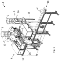
- Fig. 1 illustrates a system 1 according to at least one exemplary embodiment of the present invention.
- the system 1 comprises a plurality of cylindrical elements 2 onto which a continuous elongate element 4 is to be winded (see Fig. 8 and Fig. 9 ).
- Each cylindrical element 2 will thus receive a respective portion of the continuous elongate element 4.
- the cylindrical elements 2 may be of various different types.
- the cylindrical elements 2 are illustrated in the form of spools.
- the continuous elongate element 4 may be any suitable windable element, such as a filament, thread, wire, cable, etc.
- the post-winding section 10 which in some embodiments may be omitted, may be of any suitable form for receiving the cylindrical elements 2 after they have been provided with the thereon winded continuous elongate element 4 (or for receiving winded coils without the cylindrical elements).
- the post-winding section 10 is here illustrated as including a receiving rail, however other receiver or means of transport (such as conveyors) are conceivable to include in the post-winding section 10.
- Fig. 1 merely presents a very general overview of the system 1, and therefore the cylindrical elements 2 at the post-winding section 10 are not illustrated as having received the continuous elongate element 4 (which, as mentioned previously is shown in Fig. 8 and Fig. 9 ).
- Fig. 3 is a close-up view of details in Fig. 2 .
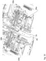
- Fig. 10 is a cross-sectional view of a part of the system, taken in a horizontal plane, thus viewed from above.
- the details on the left side have been zoomed in, i.e. the details relating to components affecting the operation of the second cylindrical element 2b.
- corresponding details are provided on the right side for affecting the operation of the first cylindrical element 2a.
- Fig. 10 is a close-up view of details in Fig. 2 .
- Fig. 10 is a cross-sectional view of a part of the system, taken in a horizontal plane, thus viewed from above.
- the details on the left side have been zoomed in, i.e. the details relating to components affecting the operation of the second cylindrical element 2b.
- corresponding details are provided on the right side for affecting the operation of the first cylindrical element 2a.
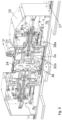
- the first motor 26a is configured to drive a first rotatable shaft 28a and the second motor 26b is configured to drive a second rotatable shaft 28b.
- the second rotatable shaft 28b is configured to receive and hold a cylindrical element on the one side of the central rotatable member 24, i.e. in this case the second cylindrical element 2b (similarly, the first rotatable shaft 28a may hold the first cylindrical element 2a on the opposite side, as seen in Fig. 10 ).
- the control unit 20 (see Fig. 1 ) is configured to control the operation of the first motor 26a and the second motor 26b.
- each one of said rotatable shafts is provided with a respective spindle.
- the second rotatable shaft 28b is illustrated as being provided with a second spindle 30b which is displaceable along the common geometrical rotational axis around which the cylindrical elements 2a, 2b and the central rotatable member 24 are configured to commonly rotate (similarly, the first rotatable shaft is provided with a displaceable first spindle).
- the second spindle 30b is provided with a second magnet 32b, here illustrated at an end of the second spindle 30b (similarly the first spindle is provided with a first magnet 32a, which can be seen in Fig. 3 ).
- the second spindle 30b may suitably be configured to rotate with the second rotatable shaft 28b in order to enable the second cylindrical element 2b (driven by the second rotatable shaft 28b) and the central rotatable member 24 (connected to the second magnet 32b) to be rotated at the same speed.
- Corresponding relationship may, of course, suitably apply to the first rotatable shaft, the first spindle and the first magnet.
- the first spindle and the second spindle are rotatably lockable to the first rotatable shaft and the second rotatable shaft, respectively.
- the first spindle and the second spindle are axially movably in a bore of the first rotatable shaft and the second rotatable shaft, respectively (as for example illustrated in the figures).
- the first spindle and the second spindle extend along the common geometrical axis (as for example seen in the figures).
- first cylindrical element 2a may be configured to do this disconnection action and also to axially remove the first cylindrical element 2a from the central rotatable member 24 which continues to rotate with the second cylindrical element 2b.
- the action of removal of the first cylindrical element 2a from the central rotatable member 24 is illustrated in Fig. 6 .
- FIG. 6 illustrates, similarly to Fig. 2 and Fig. 4 , a cross-sectional view of a part of the system, however now the first cylindrical element 2a has been removed by the first rotatable shaft 28a and the first magnet 32a has been disconnected from the magnetic portion 36 of the central rotatable member 24.
- the shaft 28a is fixed in a head part 15.
- the head part 15 is movable along a track 17.
- the movement of the head part 15 may be accomplished by a suitable actuator (not shown).
- the rotatable shafts 28a, 28b may be arranged to be movable without fixing them to a respective head part 15 that is slidable along a track 17.
- the control unit 20 may be configured to provide a third cylindrical element (for example from one of the stacks illustrated in Fig. 1 ) to the first rotatable shaft 28a so as to arrange the third cylindrical element at the previous winding position of the first cylindrical element 2a.
- the control unit 20 is suitably configured to control the first and second motor 26a, 26b in master-slave-synchronization mode in which the slave is synchronized with the rotational speed of the master, wherein at any given point in time, the one of the first and second motors 26, 26b that is operating a cylindrical element onto which the continuous elongate element is currently being winded is the master, while the other one of the first and second motors is the slave.
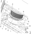
- Fig. 8 illustrates the system winding a continuous elongate element onto cylindrical elements.
- Fig. 9 is a close-up view of details of Fig. 8 .
- the system 1 comprises a feeder 22 from which the continuous elongate element 4 may be provided to cylindrical elements 2 in consecutive order.
- the cylindrical elements 2 may thus be provided in the winding section 8 of the system 1 for receiving and winding the continuous elongate element 4 onto the cylindrical elements 2.
- the same two mandrels may be reused over and over again, and thus the mandrels will alternatingly and repeatedly wind the continuous elongate element 4 (i.e. when one is fully wound, the coil is removed therefrom, while the empty one receives the continuous elongate element 4).
- the cylindrical elements are in the form of spools.
- the first cylindrical element 2a has been fully winded, and the second cylindrical element 2b has started to receive the continuous elongate element 4.
- the feeder 22 was aligned with the first cylindrical element 2a, but has in Fig.8 and Fig. 9 been displaced to become aligned with the second cylindrical element 2b.
- the displacement of the feeder is controlled by the control unit 20 ( Fig. 1 ).
- the continuous elongate element 4 has already been wound a few rotations/laps around a cylindrical winding portion 46 of the second cylindrical element 2b.
- the control unit 20 ( Fig. 1 ) has first aligned the feeder 22 with the first cylindrical element 2a, thereby winding the continuous elongate element 4 onto the first cylindrical element 2a by rotating the first cylindrical element 2a. Thereafter, while the first cylindrical element 2a, the second cylindrical element 2b and the central rotatable member 24 rotate, the control unit 20 has caused the feeder 22 to be displaced from being aligned with the first cylindrical element 2a to being aligned with the second cylindrical element 2b.
- the protrusions 42 present abutment surfaces for catching the continuous elongate element 4 as the feeder 22 is moved from being aligned with the first cylindrical element 2a to being aligned with the second cylindrical element 2b (or vice versa).
- the control unit 20 continues to rotate the second cylindrical element 2b for winding the continuous elongate element 4 from the feeder 22 onto the second cylindrical element 2b.
- the first cylindrical element 2a and the central rotatable member 24 continuous to rotate with the second cylindrical element 2b for a sufficient number of rotations until the winding of the continuous elongate element 4 on the second cylindrical element 2b has become self-locking.
- control unit may suitably be configured to apply a roller 50 against the already winded portion of the continuous elongate element 4 before the continuous elongate element is cut, and the roller 50 may suitably be kept against the already winded portion after the continuous elongate element 4 has been cut, until the first cylindrical element 2a has decelerated sufficiently (thereby reducing the risk of the already winded portion unwinding after the cutting).
Landscapes
- Engineering & Computer Science (AREA)
- Textile Engineering (AREA)
- Winding Filamentary Materials (AREA)
Claims (10)
- System (1) zum Aufwickeln eines kontinuierlichen länglichen Elements (4), wie etwa ein Draht, ein Kabel, ein Filament, ein Faden oder dergleichen, auf zylindrische Elemente (2), wie etwa Spulen, Rollen, Spindeln oder dergleichen, wobei das System Folgendes umfasst:- eine Zuführeinrichtung (22), von der aus das kontinuierliche längliche Element (4) zylindrischen Elementen (2) in aufeinanderfolgender Reihenfolge bereitstellbar ist,- eine Vielzahl von zylindrischen Elementen (2) zum Aufnehmen und Aufwickeln des kontinuierlichen länglichen Elements (4),- ein zentrales drehbares Element (24), das mit einem Eingriffsabschnitt (40) bereitgestellt ist, und- eine Steuereinheit (20),wobei die Steuereinheit (20) zu Folgendem konfiguriert ist:- Ausrichten der Zuführeinrichtung (22) mit einem ersten zylindrischen Element (2a) der Vielzahl von zylindrischen Elementen (2) zum Aufwickeln des kontinuierlichen länglichen Elements (4) auf das erste zylindrische Element (2a) durch Drehen des ersten zylindrischen Elements (2a),- Bereitstellen des ersten zylindrischen Elements (2a) und eines zweiten zylindrischen Elements (2b) der Vielzahl von zylindrischen Elementen (2) auf jeweiligen Seiten des zentralen drehbaren Elements (24) entlang einer gemeinsamen geometrischen Drehachse,- Drehen des ersten zylindrischen Elements (2a), des zweiten zylindrischen Elements (2b) und des zentralen drehbaren Elements (24) mit der gleichen Drehgeschwindigkeit,- während sich das erste zylindrische Element (2a), das zweite zylindrische Element (2b) und das zentrale drehbare Element (24) drehen, Veranlassen, dass die Zuführeinrichtung (22) von einer Ausrichtung mit dem ersten zylindrischen Element (2a) in eine Ausrichtung mit dem zweiten zylindrischen Element (2b) verschoben wird, wobei die Verschiebung veranlasst, dass das kontinuierliche längliche Element (4) in Eingriff mit dem Eingriffsabschnitt (40) des zentralen drehbaren Elements (24) kommt, wodurch verhindert wird, dass der bereits aufgewickelte Abschnitt des kontinuierlichen länglichen Elements (4) von dem ersten zylindrischen Element (2a) abgewickelt wird, und- Weiterdrehen des zweiten zylindrischen Elements (2b) zum Aufwickeln des kontinuierlichen länglichen Elements (4) von der Zuführeinrichtung (22) auf das zweite zylindrische Element (2b),wobei das System ferner Folgendes umfasst:- einen ersten Motor (26a), der dazu konfiguriert ist, eine erste drehbare Welle (28a) anzutreiben, wobei die erste drehbare Welle (28a) dazu konfiguriert ist, ein zylindrisches Element (2a) auf einer Seite des zentralen drehbaren Elements (24) aufzunehmen und zu halten,- einen zweiten Motor (26b), der dazu konfiguriert ist, eine zweite drehbare Welle (28b) anzutreiben, wobei die zweite drehbare Welle (28b) dazu konfiguriert ist, ein zylindrisches Element (2b) auf der gegenüberliegenden Seite des zentralen drehbaren Elements (24) aufzunehmen und zu halten,wobei die Steuereinheit (20) dazu konfiguriert ist, den Betrieb des ersten und des zweiten Motors (26a, 26b) zu steuern,wobei die erste drehbare Welle (28a) mit einer ersten Spindel bereitgestellt ist, die entlang der geometrischen Drehachse verschiebbar ist, wobei die erste Spindel mit einem ersten Magneten (32a) bereitgestellt ist,wobei die zweite drehbare Welle (28b) mit einer zweiten Spindel (30b) bereitgestellt ist, die entlang der geometrischen Drehachse verschiebbar ist, wobei die zweite Spindel (30b) mit einem zweiten Magneten (32b) bereitgestellt ist,wobei das zentrale drehbare Element (24) mit einem oder mehreren magnetischen Abschnitten (36) bereitgestellt ist, um das zentrale drehbare Element (24) magnetisch mit dem ersten Magneten (32a) und dem zweiten Magneten (32b) zu verbinden, um das zentrale drehbare Element (24) in die Lage zu versetzen, sich mit den zylindrischen Elementen (2a, 2b), die von der ersten und der zweiten drehbaren Welle (28a, 28b) gehalten werden, zu drehen,wobei die axiale Verschiebung der ersten Spindel relativ zu der axialen Verschiebung der ersten drehbaren Welle (28a) individuell steuerbar ist und wobei die axiale Verschiebung der zweiten Spindel (30b) relativ zu der axialen Verschiebung der zweiten drehbaren Welle (28b) individuell steuerbar ist.
- System (1) nach Anspruch 1, wobei jedes zylindrische Element (2) einen zylindrischen Aufwickelabschnitt (46) umfasst, der durch einen Wandabschnitt (48) an jedem Ende des zylindrischen Aufwickelabschnitts (46) begrenzt ist, wobei, wenn sich das erste zylindrische Element (2a), das zweite zylindrische Element (2b) und das zentrale drehbare Element (24) um die gemeinsame geometrische Drehachse drehen, der radiale Abstand zwischen der gemeinsamen geometrischen Drehachse und dem Eingriffsabschnitt (40) größer ist als der radiale Abstand zwischen der gemeinsamen geometrischen Drehachse und einem Umfang der Wandabschnitte (48) des ersten und des zweiten zylindrischen Elements (2a, 2b).
- System (1) nach einem der Ansprüche 1-2, wobei der Eingriffsabschnitt (40) des zentralen drehbaren Elements (24) eine Vielzahl von Vorsprüngen (42) umfasst, wie etwa zahnartige, hakenartige oder stachelartige Vorsprünge, wobei die Vielzahl von Vorsprüngen (42) Anschlagflächen zum Auffangen des kontinuierlichen länglichen Elements (4) aufweist, wenn die Zuführeinrichtung (22) von einer Ausrichtung mit dem ersten zylindrischen Element (2a) in eine Ausrichtung mit dem zweiten zylindrischen Element (2b) bewegt wird.
- System (1) nach einem der Ansprüche 1-3, umfassend einen Schneider (38), wobei die Steuereinheit (20) dazu konfiguriert ist, den Schneider (38) zu steuern, um das kontinuierliche längliche Element (4) an seiner Eingriffsstelle mit dem Eingriffsabschnitt (40) zu schneiden, um es in zwei Abschnitte aufzuteilen, einen ersten Abschnitt, der bereits auf das erste zylindrische Element (2a) gewickelt ist, und einen zweiten Abschnitt, der noch auf das zweite zylindrische Element (2b) gewickelt wird.
- System (1) nach Anspruch 4, wobei das zentrale drehbare Element (24) einen kreisförmigen Schlitz (44) umfasst, der sich entlang des Umfangs des zentralen drehbaren Elements (24) erstreckt, wobei der kreisförmige Schlitz (44) dazu konfiguriert ist, den Schneider (38) aufzunehmen, um den Schneider (38) in die Lage zu versetzen, das kontinuierliche längliche Element (4) in zwei Abschnitte aufzuteilen.
- System (1) nach einem der Ansprüche 4-5, wobei die Steuereinheit (20), nachdem der Schneider (38) das kontinuierliche längliche Element (4) geschnitten hat, dazu konfiguriert ist, den ersten Magneten (32a) von dem einen oder den mehreren magnetischen Abschnitten (36) des zentralen drehbaren Elements (24) zu trennen und das erste zylindrische Element (2a) axial von dem zentralen drehbaren Element (24) zu entfernen, das sich weiterhin mit dem zweiten zylindrischen Element (2b) dreht.
- System (1) nach Anspruch 6, wobei die Steuereinheit (20) dazu konfiguriert ist, der ersten drehbaren Welle (28a) ein drittes zylindrisches Element (2) bereitzustellen, um das dritte zylindrische Element (2) an der vorherigen Aufwickelposition des ersten zylindrischen Elements (2a) anzuordnen, so dass sich das zweite zylindrische Element (2b) und das dritte zylindrische Element (2) auf jeweiligen Seiten des zentralen drehbaren Elements (24) befinden, so dass das zweite zylindrische Element (2b), das dritte zylindrische Element (2) und das zentrale drehbare Element (24) dieselbe geometrische Drehachse haben und sich mit derselben Drehgeschwindigkeit drehen.
- System (1) nach einem der Ansprüche 1-7, wobei die Steuereinheit (20) dazu konfiguriert ist, den ersten und den zweiten Motor (26a, 26b) in einem Master-Slave-Synchronisierungsmodus zu steuern, in dem der Slave mit der Drehgeschwindigkeit des Masters synchronisiert ist, wobei zu einem beliebigen Zeitpunkt derjenige des ersten und des zweiten Motors (26a, 26b), der ein zylindrisches Element (2) betreibt, auf welches das kontinuierliche längliche Element (4) aktuell aufgewickelt wird, der Master ist, während der andere des ersten und des zweiten Motors (26a, 26b) der Slave ist.
- System (1) nach Anspruch 4 oder einem der Ansprüche 5-8 in Abhängigkeit von Anspruch 4, umfassend mindestens eine Rolle, wobei die Steuereinheit (20) dazu konfiguriert ist, die mindestens eine Rolle (50) gegen den bereits aufgewickelten Abschnitt des kontinuierlichen länglichen Elements (4) zu drücken, bevor der Schneider (38) das kontinuierliche längliche Element (4) schneidet.
- System (1) nach einem der Ansprüche 1-9, wobei die Steuereinheit (20) dazu konfiguriert ist, Eingabeparameterwerte in Bezug auf Abmessungen eines einzelnen zylindrischen Elements (2) der Vielzahl von zylindrischen Elementen und/oder in Bezug auf Abmessungen des kontinuierlichen länglichen Elements (4) zu empfangen, wobei die Steuereinheit (20) dazu konfiguriert ist, basierend auf den empfangenen Eingabeparameterwerten zu bestimmen, wann das Aufwickeln des kontinuierlichen länglichen Elements (4) von dem ersten zylindrischen Element (2a) auf das zweite zylindrische Element (2b) umzuschalten ist.
Priority Applications (2)
| Application Number | Priority Date | Filing Date | Title |
|---|---|---|---|
| EP21162123.0A EP4056508B1 (de) | 2021-03-11 | 2021-03-11 | Verfahren und system zum aufwickeln eines kontinuierlichen länglichen elements |
| US17/690,172 US12221316B2 (en) | 2021-03-11 | 2022-03-09 | Method and system for winding a continuous elongate element |
Applications Claiming Priority (1)
| Application Number | Priority Date | Filing Date | Title |
|---|---|---|---|
| EP21162123.0A EP4056508B1 (de) | 2021-03-11 | 2021-03-11 | Verfahren und system zum aufwickeln eines kontinuierlichen länglichen elements |
Publications (3)
| Publication Number | Publication Date |
|---|---|
| EP4056508A1 EP4056508A1 (de) | 2022-09-14 |
| EP4056508C0 EP4056508C0 (de) | 2025-04-16 |
| EP4056508B1 true EP4056508B1 (de) | 2025-04-16 |
Family
ID=74871308
Family Applications (1)
| Application Number | Title | Priority Date | Filing Date |
|---|---|---|---|
| EP21162123.0A Active EP4056508B1 (de) | 2021-03-11 | 2021-03-11 | Verfahren und system zum aufwickeln eines kontinuierlichen länglichen elements |
Country Status (2)
| Country | Link |
|---|---|
| US (1) | US12221316B2 (de) |
| EP (1) | EP4056508B1 (de) |
Family Cites Families (9)
| Publication number | Priority date | Publication date | Assignee | Title |
|---|---|---|---|---|
| US2735629A (en) * | 1956-02-21 | Take-up reel apparatus | ||
| US2902230A (en) * | 1957-11-27 | 1959-09-01 | Western Electric Co | Snagging wheel |
| US3080128A (en) * | 1960-10-06 | 1963-03-05 | Western Electric Co | Strand-reeling apparatus |
| US3051403A (en) * | 1961-01-09 | 1962-08-28 | Western Electric Co | Cutover mechanisms for strand-reeling installations |
| US3368765A (en) * | 1966-08-03 | 1968-02-13 | Syncro Mach Co | Continuous spooling of aluminum wire |
| US3661335A (en) * | 1970-04-24 | 1972-05-09 | Northern Electric Co | Anti-ricochet wire guard |
| DE2403861C2 (de) * | 1973-03-26 | 1981-11-12 | Veb Kabelwerk Oberspree (Kwo), Ddr 1160 Berlin | Wickelvorrichtung für automatische Ringwickler |
| US4848687A (en) * | 1986-12-05 | 1989-07-18 | American Telephone And Telegraph Company, At&T Technologies, Inc. | Methods of taking up optical fiber |
| US20110215182A1 (en) * | 2010-03-04 | 2011-09-08 | Kiswel, Inc. | Methods and Apparatus for Continuous Winding of Spools and Products Made Therefrom |
-
2021
- 2021-03-11 EP EP21162123.0A patent/EP4056508B1/de active Active
-
2022
- 2022-03-09 US US17/690,172 patent/US12221316B2/en active Active
Also Published As
| Publication number | Publication date |
|---|---|
| US20220289515A1 (en) | 2022-09-15 |
| EP4056508C0 (de) | 2025-04-16 |
| US12221316B2 (en) | 2025-02-11 |
| EP4056508A1 (de) | 2022-09-14 |
Similar Documents
| Publication | Publication Date | Title |
|---|---|---|
| JP5858575B2 (ja) | コイルの多連巻線装置及びその多連巻線方法 | |
| JP6110477B2 (ja) | プリプレグテープのスリット加工の装置及び方法 | |
| US20110215182A1 (en) | Methods and Apparatus for Continuous Winding of Spools and Products Made Therefrom | |
| WO2004015845A1 (ja) | コイル形成方法及びコイル形成装置 | |
| US20090038759A1 (en) | Filament Winding Automated System | |
| EP4194384B1 (de) | Spulenhandhabungsroboter und verfahren zur handhabung von rollen mit bahnmaterial | |
| CN218057975U (zh) | 衬里卷轴、包括该衬里卷轴的盒及释放工位 | |
| EP4056508B1 (de) | Verfahren und system zum aufwickeln eines kontinuierlichen länglichen elements | |
| CN1094673C (zh) | 制造波形分布绕组的方法和设备 | |
| CN107697728A (zh) | 线轴、卷绕机、卷绕线轴的方法和计算机可读的存储介质 | |
| JP4403714B2 (ja) | コイル形成挿入装置及びコイル形成挿入方法 | |
| FI103399B (fi) | Menetelmä ja sovitelma kaksoispuolauksen yhteydessä | |
| GB2039805A (en) | Machine for winding and inserting coils | |
| CA2792178C (en) | A web rewinding apparatus | |
| JP2024153754A (ja) | ストックリールからタイヤ部品を巻き戻すための巻き戻しシステム、アセンブリ、および方法 | |
| JP4456053B2 (ja) | コイルの巻線システム及び巻線方法 | |
| US4884758A (en) | Self-loading wire winding assembly and method | |
| WO2015056215A1 (en) | High performance rewinding machine of extendable film | |
| US2789775A (en) | Layer winding and reeling | |
| CN117637337B (zh) | 分层间隔线圈绕线方法 | |
| CN222922688U (zh) | 一种可快速换筒的丝线卷绕机 | |
| CN220392964U (zh) | 一种丝材收放线绕丝机 | |
| US5341998A (en) | Pin hub for wire reel | |
| WO2024203894A1 (ja) | 巻取装置および巻取方法 | |
| US6343762B1 (en) | Winders for electric motor armatures |
Legal Events
| Date | Code | Title | Description |
|---|---|---|---|
| PUAI | Public reference made under article 153(3) epc to a published international application that has entered the european phase |
Free format text: ORIGINAL CODE: 0009012 |
|
| STAA | Information on the status of an ep patent application or granted ep patent |
Free format text: STATUS: THE APPLICATION HAS BEEN PUBLISHED |
|
| AK | Designated contracting states |
Kind code of ref document: A1 Designated state(s): AL AT BE BG CH CY CZ DE DK EE ES FI FR GB GR HR HU IE IS IT LI LT LU LV MC MK MT NL NO PL PT RO RS SE SI SK SM TR |
|
| STAA | Information on the status of an ep patent application or granted ep patent |
Free format text: STATUS: REQUEST FOR EXAMINATION WAS MADE |
|
| 17P | Request for examination filed |
Effective date: 20230302 |
|
| RBV | Designated contracting states (corrected) |
Designated state(s): AL AT BE BG CH CY CZ DE DK EE ES FI FR GB GR HR HU IE IS IT LI LT LU LV MC MK MT NL NO PL PT RO RS SE SI SK SM TR |
|
| STAA | Information on the status of an ep patent application or granted ep patent |
Free format text: STATUS: EXAMINATION IS IN PROGRESS |
|
| 17Q | First examination report despatched |
Effective date: 20240214 |
|
| GRAP | Despatch of communication of intention to grant a patent |
Free format text: ORIGINAL CODE: EPIDOSNIGR1 |
|
| STAA | Information on the status of an ep patent application or granted ep patent |
Free format text: STATUS: GRANT OF PATENT IS INTENDED |
|
| INTG | Intention to grant announced |
Effective date: 20241209 |
|
| GRAS | Grant fee paid |
Free format text: ORIGINAL CODE: EPIDOSNIGR3 |
|
| GRAA | (expected) grant |
Free format text: ORIGINAL CODE: 0009210 |
|
| STAA | Information on the status of an ep patent application or granted ep patent |
Free format text: STATUS: THE PATENT HAS BEEN GRANTED |
|
| AK | Designated contracting states |
Kind code of ref document: B1 Designated state(s): AL AT BE BG CH CY CZ DE DK EE ES FI FR GB GR HR HU IE IS IT LI LT LU LV MC MK MT NL NO PL PT RO RS SE SI SK SM TR |
|
| REG | Reference to a national code |
Ref country code: GB Ref legal event code: FG4D |
|
| REG | Reference to a national code |
Ref country code: CH Ref legal event code: EP Ref country code: DE Ref legal event code: R096 Ref document number: 602021029108 Country of ref document: DE |
|
| REG | Reference to a national code |
Ref country code: IE Ref legal event code: FG4D |
|
| U01 | Request for unitary effect filed |
Effective date: 20250502 |
|
| U07 | Unitary effect registered |
Designated state(s): AT BE BG DE DK EE FI FR IT LT LU LV MT NL PT RO SE SI Effective date: 20250509 |
|
| PG25 | Lapsed in a contracting state [announced via postgrant information from national office to epo] |
Ref country code: ES Free format text: LAPSE BECAUSE OF FAILURE TO SUBMIT A TRANSLATION OF THE DESCRIPTION OR TO PAY THE FEE WITHIN THE PRESCRIBED TIME-LIMIT Effective date: 20250416 |
|
| PG25 | Lapsed in a contracting state [announced via postgrant information from national office to epo] |
Ref country code: NO Free format text: LAPSE BECAUSE OF FAILURE TO SUBMIT A TRANSLATION OF THE DESCRIPTION OR TO PAY THE FEE WITHIN THE PRESCRIBED TIME-LIMIT Effective date: 20250716 Ref country code: GR Free format text: LAPSE BECAUSE OF FAILURE TO SUBMIT A TRANSLATION OF THE DESCRIPTION OR TO PAY THE FEE WITHIN THE PRESCRIBED TIME-LIMIT Effective date: 20250717 |
|
| PG25 | Lapsed in a contracting state [announced via postgrant information from national office to epo] |
Ref country code: PL Free format text: LAPSE BECAUSE OF FAILURE TO SUBMIT A TRANSLATION OF THE DESCRIPTION OR TO PAY THE FEE WITHIN THE PRESCRIBED TIME-LIMIT Effective date: 20250416 |
|
| PG25 | Lapsed in a contracting state [announced via postgrant information from national office to epo] |
Ref country code: HR Free format text: LAPSE BECAUSE OF FAILURE TO SUBMIT A TRANSLATION OF THE DESCRIPTION OR TO PAY THE FEE WITHIN THE PRESCRIBED TIME-LIMIT Effective date: 20250416 |
|
| PG25 | Lapsed in a contracting state [announced via postgrant information from national office to epo] |
Ref country code: RS Free format text: LAPSE BECAUSE OF FAILURE TO SUBMIT A TRANSLATION OF THE DESCRIPTION OR TO PAY THE FEE WITHIN THE PRESCRIBED TIME-LIMIT Effective date: 20250716 |
|
| PG25 | Lapsed in a contracting state [announced via postgrant information from national office to epo] |
Ref country code: IS Free format text: LAPSE BECAUSE OF FAILURE TO SUBMIT A TRANSLATION OF THE DESCRIPTION OR TO PAY THE FEE WITHIN THE PRESCRIBED TIME-LIMIT Effective date: 20250816 |