EP4056459B1 - Ship and method of loading liquefied carbon dioxide into ship - Google Patents
Ship and method of loading liquefied carbon dioxide into ship Download PDFInfo
- Publication number
- EP4056459B1 EP4056459B1 EP20901800.1A EP20901800A EP4056459B1 EP 4056459 B1 EP4056459 B1 EP 4056459B1 EP 20901800 A EP20901800 A EP 20901800A EP 4056459 B1 EP4056459 B1 EP 4056459B1
- Authority
- EP
- European Patent Office
- Prior art keywords
- carbon dioxide
- liquefied carbon
- tank
- valve
- loading pipe
- Prior art date
- Legal status (The legal status is an assumption and is not a legal conclusion. Google has not performed a legal analysis and makes no representation as to the accuracy of the status listed.)
- Active
Links
Images



Classifications
-
- B—PERFORMING OPERATIONS; TRANSPORTING
- B63—SHIPS OR OTHER WATERBORNE VESSELS; RELATED EQUIPMENT
- B63B—SHIPS OR OTHER WATERBORNE VESSELS; EQUIPMENT FOR SHIPPING
- B63B25/00—Load-accommodating arrangements, e.g. stowing, trimming; Vessels characterised thereby
- B63B25/02—Load-accommodating arrangements, e.g. stowing, trimming; Vessels characterised thereby for bulk goods
- B63B25/08—Load-accommodating arrangements, e.g. stowing, trimming; Vessels characterised thereby for bulk goods fluid
- B63B25/12—Load-accommodating arrangements, e.g. stowing, trimming; Vessels characterised thereby for bulk goods fluid closed
- B63B25/16—Load-accommodating arrangements, e.g. stowing, trimming; Vessels characterised thereby for bulk goods fluid closed heat-insulated
-
- B—PERFORMING OPERATIONS; TRANSPORTING
- B63—SHIPS OR OTHER WATERBORNE VESSELS; RELATED EQUIPMENT
- B63B—SHIPS OR OTHER WATERBORNE VESSELS; EQUIPMENT FOR SHIPPING
- B63B27/00—Arrangement of ship-based loading or unloading equipment for cargo or passengers
- B63B27/24—Arrangement of ship-based loading or unloading equipment for cargo or passengers of pipe-lines
-
- B—PERFORMING OPERATIONS; TRANSPORTING
- B63—SHIPS OR OTHER WATERBORNE VESSELS; RELATED EQUIPMENT
- B63B—SHIPS OR OTHER WATERBORNE VESSELS; EQUIPMENT FOR SHIPPING
- B63B27/00—Arrangement of ship-based loading or unloading equipment for cargo or passengers
- B63B27/30—Arrangement of ship-based loading or unloading equipment for transfer at sea between ships or between ships and off-shore structures
- B63B27/34—Arrangement of ship-based loading or unloading equipment for transfer at sea between ships or between ships and off-shore structures using pipe-lines
-
- B—PERFORMING OPERATIONS; TRANSPORTING
- B63—SHIPS OR OTHER WATERBORNE VESSELS; RELATED EQUIPMENT
- B63B—SHIPS OR OTHER WATERBORNE VESSELS; EQUIPMENT FOR SHIPPING
- B63B79/00—Monitoring properties or operating parameters of vessels in operation
- B63B79/10—Monitoring properties or operating parameters of vessels in operation using sensors, e.g. pressure sensors, strain gauges or accelerometers
-
- F—MECHANICAL ENGINEERING; LIGHTING; HEATING; WEAPONS; BLASTING
- F17—STORING OR DISTRIBUTING GASES OR LIQUIDS
- F17C—VESSELS FOR CONTAINING OR STORING COMPRESSED, LIQUEFIED OR SOLIDIFIED GASES; FIXED-CAPACITY GAS-HOLDERS; FILLING VESSELS WITH, OR DISCHARGING FROM VESSELS, COMPRESSED, LIQUEFIED, OR SOLIDIFIED GASES
- F17C13/00—Details of vessels or of the filling or discharging of vessels
- F17C13/02—Special adaptations of indicating, measuring, or monitoring equipment
- F17C13/021—Special adaptations of indicating, measuring, or monitoring equipment having the height as the parameter
-
- F—MECHANICAL ENGINEERING; LIGHTING; HEATING; WEAPONS; BLASTING
- F17—STORING OR DISTRIBUTING GASES OR LIQUIDS
- F17C—VESSELS FOR CONTAINING OR STORING COMPRESSED, LIQUEFIED OR SOLIDIFIED GASES; FIXED-CAPACITY GAS-HOLDERS; FILLING VESSELS WITH, OR DISCHARGING FROM VESSELS, COMPRESSED, LIQUEFIED, OR SOLIDIFIED GASES
- F17C13/00—Details of vessels or of the filling or discharging of vessels
- F17C13/02—Special adaptations of indicating, measuring, or monitoring equipment
- F17C13/025—Special adaptations of indicating, measuring, or monitoring equipment having the pressure as the parameter
-
- F—MECHANICAL ENGINEERING; LIGHTING; HEATING; WEAPONS; BLASTING
- F17—STORING OR DISTRIBUTING GASES OR LIQUIDS
- F17C—VESSELS FOR CONTAINING OR STORING COMPRESSED, LIQUEFIED OR SOLIDIFIED GASES; FIXED-CAPACITY GAS-HOLDERS; FILLING VESSELS WITH, OR DISCHARGING FROM VESSELS, COMPRESSED, LIQUEFIED, OR SOLIDIFIED GASES
- F17C13/00—Details of vessels or of the filling or discharging of vessels
- F17C13/04—Arrangement or mounting of valves
-
- F—MECHANICAL ENGINEERING; LIGHTING; HEATING; WEAPONS; BLASTING
- F17—STORING OR DISTRIBUTING GASES OR LIQUIDS
- F17C—VESSELS FOR CONTAINING OR STORING COMPRESSED, LIQUEFIED OR SOLIDIFIED GASES; FIXED-CAPACITY GAS-HOLDERS; FILLING VESSELS WITH, OR DISCHARGING FROM VESSELS, COMPRESSED, LIQUEFIED, OR SOLIDIFIED GASES
- F17C2201/00—Vessel construction, in particular geometry, arrangement or size
- F17C2201/01—Shape
- F17C2201/0104—Shape cylindrical
- F17C2201/0109—Shape cylindrical with exteriorly curved end-piece
-
- F—MECHANICAL ENGINEERING; LIGHTING; HEATING; WEAPONS; BLASTING
- F17—STORING OR DISTRIBUTING GASES OR LIQUIDS
- F17C—VESSELS FOR CONTAINING OR STORING COMPRESSED, LIQUEFIED OR SOLIDIFIED GASES; FIXED-CAPACITY GAS-HOLDERS; FILLING VESSELS WITH, OR DISCHARGING FROM VESSELS, COMPRESSED, LIQUEFIED, OR SOLIDIFIED GASES
- F17C2201/00—Vessel construction, in particular geometry, arrangement or size
- F17C2201/01—Shape
- F17C2201/0128—Shape spherical or elliptical
-
- F—MECHANICAL ENGINEERING; LIGHTING; HEATING; WEAPONS; BLASTING
- F17—STORING OR DISTRIBUTING GASES OR LIQUIDS
- F17C—VESSELS FOR CONTAINING OR STORING COMPRESSED, LIQUEFIED OR SOLIDIFIED GASES; FIXED-CAPACITY GAS-HOLDERS; FILLING VESSELS WITH, OR DISCHARGING FROM VESSELS, COMPRESSED, LIQUEFIED, OR SOLIDIFIED GASES
- F17C2201/00—Vessel construction, in particular geometry, arrangement or size
- F17C2201/03—Orientation
- F17C2201/035—Orientation with substantially horizontal main axis
-
- F—MECHANICAL ENGINEERING; LIGHTING; HEATING; WEAPONS; BLASTING
- F17—STORING OR DISTRIBUTING GASES OR LIQUIDS
- F17C—VESSELS FOR CONTAINING OR STORING COMPRESSED, LIQUEFIED OR SOLIDIFIED GASES; FIXED-CAPACITY GAS-HOLDERS; FILLING VESSELS WITH, OR DISCHARGING FROM VESSELS, COMPRESSED, LIQUEFIED, OR SOLIDIFIED GASES
- F17C2201/00—Vessel construction, in particular geometry, arrangement or size
- F17C2201/05—Size
- F17C2201/052—Size large (>1000 m3)
-
- F—MECHANICAL ENGINEERING; LIGHTING; HEATING; WEAPONS; BLASTING
- F17—STORING OR DISTRIBUTING GASES OR LIQUIDS
- F17C—VESSELS FOR CONTAINING OR STORING COMPRESSED, LIQUEFIED OR SOLIDIFIED GASES; FIXED-CAPACITY GAS-HOLDERS; FILLING VESSELS WITH, OR DISCHARGING FROM VESSELS, COMPRESSED, LIQUEFIED, OR SOLIDIFIED GASES
- F17C2201/00—Vessel construction, in particular geometry, arrangement or size
- F17C2201/05—Size
- F17C2201/054—Size medium (>1 m3)
-
- F—MECHANICAL ENGINEERING; LIGHTING; HEATING; WEAPONS; BLASTING
- F17—STORING OR DISTRIBUTING GASES OR LIQUIDS
- F17C—VESSELS FOR CONTAINING OR STORING COMPRESSED, LIQUEFIED OR SOLIDIFIED GASES; FIXED-CAPACITY GAS-HOLDERS; FILLING VESSELS WITH, OR DISCHARGING FROM VESSELS, COMPRESSED, LIQUEFIED, OR SOLIDIFIED GASES
- F17C2205/00—Vessel construction, in particular mounting arrangements, attachments or identifications means
- F17C2205/01—Mounting arrangements
- F17C2205/0123—Mounting arrangements characterised by number of vessels
- F17C2205/013—Two or more vessels
-
- F—MECHANICAL ENGINEERING; LIGHTING; HEATING; WEAPONS; BLASTING
- F17—STORING OR DISTRIBUTING GASES OR LIQUIDS
- F17C—VESSELS FOR CONTAINING OR STORING COMPRESSED, LIQUEFIED OR SOLIDIFIED GASES; FIXED-CAPACITY GAS-HOLDERS; FILLING VESSELS WITH, OR DISCHARGING FROM VESSELS, COMPRESSED, LIQUEFIED, OR SOLIDIFIED GASES
- F17C2221/00—Handled fluid, in particular type of fluid
- F17C2221/01—Pure fluids
- F17C2221/013—Carbon dioxide
-
- F—MECHANICAL ENGINEERING; LIGHTING; HEATING; WEAPONS; BLASTING
- F17—STORING OR DISTRIBUTING GASES OR LIQUIDS
- F17C—VESSELS FOR CONTAINING OR STORING COMPRESSED, LIQUEFIED OR SOLIDIFIED GASES; FIXED-CAPACITY GAS-HOLDERS; FILLING VESSELS WITH, OR DISCHARGING FROM VESSELS, COMPRESSED, LIQUEFIED, OR SOLIDIFIED GASES
- F17C2223/00—Handled fluid before transfer, i.e. state of fluid when stored in the vessel or before transfer from the vessel
- F17C2223/01—Handled fluid before transfer, i.e. state of fluid when stored in the vessel or before transfer from the vessel characterised by the phase
- F17C2223/0146—Two-phase
- F17C2223/0153—Liquefied gas, e.g. LPG, GPL
- F17C2223/0161—Liquefied gas, e.g. LPG, GPL cryogenic, e.g. LNG, GNL, PLNG
-
- F—MECHANICAL ENGINEERING; LIGHTING; HEATING; WEAPONS; BLASTING
- F17—STORING OR DISTRIBUTING GASES OR LIQUIDS
- F17C—VESSELS FOR CONTAINING OR STORING COMPRESSED, LIQUEFIED OR SOLIDIFIED GASES; FIXED-CAPACITY GAS-HOLDERS; FILLING VESSELS WITH, OR DISCHARGING FROM VESSELS, COMPRESSED, LIQUEFIED, OR SOLIDIFIED GASES
- F17C2223/00—Handled fluid before transfer, i.e. state of fluid when stored in the vessel or before transfer from the vessel
- F17C2223/01—Handled fluid before transfer, i.e. state of fluid when stored in the vessel or before transfer from the vessel characterised by the phase
- F17C2223/0192—Three-phase, e.g. CO2 at triple point
-
- F—MECHANICAL ENGINEERING; LIGHTING; HEATING; WEAPONS; BLASTING
- F17—STORING OR DISTRIBUTING GASES OR LIQUIDS
- F17C—VESSELS FOR CONTAINING OR STORING COMPRESSED, LIQUEFIED OR SOLIDIFIED GASES; FIXED-CAPACITY GAS-HOLDERS; FILLING VESSELS WITH, OR DISCHARGING FROM VESSELS, COMPRESSED, LIQUEFIED, OR SOLIDIFIED GASES
- F17C2223/00—Handled fluid before transfer, i.e. state of fluid when stored in the vessel or before transfer from the vessel
- F17C2223/03—Handled fluid before transfer, i.e. state of fluid when stored in the vessel or before transfer from the vessel characterised by the pressure level
- F17C2223/033—Small pressure, e.g. for liquefied gas
-
- F—MECHANICAL ENGINEERING; LIGHTING; HEATING; WEAPONS; BLASTING
- F17—STORING OR DISTRIBUTING GASES OR LIQUIDS
- F17C—VESSELS FOR CONTAINING OR STORING COMPRESSED, LIQUEFIED OR SOLIDIFIED GASES; FIXED-CAPACITY GAS-HOLDERS; FILLING VESSELS WITH, OR DISCHARGING FROM VESSELS, COMPRESSED, LIQUEFIED, OR SOLIDIFIED GASES
- F17C2225/00—Handled fluid after transfer, i.e. state of fluid after transfer from the vessel
- F17C2225/01—Handled fluid after transfer, i.e. state of fluid after transfer from the vessel characterised by the phase
- F17C2225/0192—Three-phase, e.g. CO2 at triple point
-
- F—MECHANICAL ENGINEERING; LIGHTING; HEATING; WEAPONS; BLASTING
- F17—STORING OR DISTRIBUTING GASES OR LIQUIDS
- F17C—VESSELS FOR CONTAINING OR STORING COMPRESSED, LIQUEFIED OR SOLIDIFIED GASES; FIXED-CAPACITY GAS-HOLDERS; FILLING VESSELS WITH, OR DISCHARGING FROM VESSELS, COMPRESSED, LIQUEFIED, OR SOLIDIFIED GASES
- F17C2225/00—Handled fluid after transfer, i.e. state of fluid after transfer from the vessel
- F17C2225/04—Handled fluid after transfer, i.e. state of fluid after transfer from the vessel characterised by other properties of handled fluid after transfer
- F17C2225/042—Localisation of the filling point
- F17C2225/043—Localisation of the filling point in the gas
- F17C2225/045—Localisation of the filling point in the gas with a dip tube
-
- F—MECHANICAL ENGINEERING; LIGHTING; HEATING; WEAPONS; BLASTING
- F17—STORING OR DISTRIBUTING GASES OR LIQUIDS
- F17C—VESSELS FOR CONTAINING OR STORING COMPRESSED, LIQUEFIED OR SOLIDIFIED GASES; FIXED-CAPACITY GAS-HOLDERS; FILLING VESSELS WITH, OR DISCHARGING FROM VESSELS, COMPRESSED, LIQUEFIED, OR SOLIDIFIED GASES
- F17C2225/00—Handled fluid after transfer, i.e. state of fluid after transfer from the vessel
- F17C2225/04—Handled fluid after transfer, i.e. state of fluid after transfer from the vessel characterised by other properties of handled fluid after transfer
- F17C2225/042—Localisation of the filling point
- F17C2225/046—Localisation of the filling point in the liquid
- F17C2225/047—Localisation of the filling point in the liquid with a dip tube
-
- F—MECHANICAL ENGINEERING; LIGHTING; HEATING; WEAPONS; BLASTING
- F17—STORING OR DISTRIBUTING GASES OR LIQUIDS
- F17C—VESSELS FOR CONTAINING OR STORING COMPRESSED, LIQUEFIED OR SOLIDIFIED GASES; FIXED-CAPACITY GAS-HOLDERS; FILLING VESSELS WITH, OR DISCHARGING FROM VESSELS, COMPRESSED, LIQUEFIED, OR SOLIDIFIED GASES
- F17C2227/00—Transfer of fluids, i.e. method or means for transferring the fluid; Heat exchange with the fluid
- F17C2227/04—Methods for emptying or filling
-
- F—MECHANICAL ENGINEERING; LIGHTING; HEATING; WEAPONS; BLASTING
- F17—STORING OR DISTRIBUTING GASES OR LIQUIDS
- F17C—VESSELS FOR CONTAINING OR STORING COMPRESSED, LIQUEFIED OR SOLIDIFIED GASES; FIXED-CAPACITY GAS-HOLDERS; FILLING VESSELS WITH, OR DISCHARGING FROM VESSELS, COMPRESSED, LIQUEFIED, OR SOLIDIFIED GASES
- F17C2250/00—Accessories; Control means; Indicating, measuring or monitoring of parameters
- F17C2250/03—Control means
- F17C2250/032—Control means using computers
-
- F—MECHANICAL ENGINEERING; LIGHTING; HEATING; WEAPONS; BLASTING
- F17—STORING OR DISTRIBUTING GASES OR LIQUIDS
- F17C—VESSELS FOR CONTAINING OR STORING COMPRESSED, LIQUEFIED OR SOLIDIFIED GASES; FIXED-CAPACITY GAS-HOLDERS; FILLING VESSELS WITH, OR DISCHARGING FROM VESSELS, COMPRESSED, LIQUEFIED, OR SOLIDIFIED GASES
- F17C2250/00—Accessories; Control means; Indicating, measuring or monitoring of parameters
- F17C2250/04—Indicating or measuring of parameters as input values
- F17C2250/0404—Parameters indicated or measured
- F17C2250/0408—Level of content in the vessel
-
- F—MECHANICAL ENGINEERING; LIGHTING; HEATING; WEAPONS; BLASTING
- F17—STORING OR DISTRIBUTING GASES OR LIQUIDS
- F17C—VESSELS FOR CONTAINING OR STORING COMPRESSED, LIQUEFIED OR SOLIDIFIED GASES; FIXED-CAPACITY GAS-HOLDERS; FILLING VESSELS WITH, OR DISCHARGING FROM VESSELS, COMPRESSED, LIQUEFIED, OR SOLIDIFIED GASES
- F17C2250/00—Accessories; Control means; Indicating, measuring or monitoring of parameters
- F17C2250/04—Indicating or measuring of parameters as input values
- F17C2250/0404—Parameters indicated or measured
- F17C2250/043—Pressure
-
- F—MECHANICAL ENGINEERING; LIGHTING; HEATING; WEAPONS; BLASTING
- F17—STORING OR DISTRIBUTING GASES OR LIQUIDS
- F17C—VESSELS FOR CONTAINING OR STORING COMPRESSED, LIQUEFIED OR SOLIDIFIED GASES; FIXED-CAPACITY GAS-HOLDERS; FILLING VESSELS WITH, OR DISCHARGING FROM VESSELS, COMPRESSED, LIQUEFIED, OR SOLIDIFIED GASES
- F17C2260/00—Purposes of gas storage and gas handling
- F17C2260/02—Improving properties related to fluid or fluid transfer
- F17C2260/026—Improving properties related to fluid or fluid transfer by calculation
-
- F—MECHANICAL ENGINEERING; LIGHTING; HEATING; WEAPONS; BLASTING
- F17—STORING OR DISTRIBUTING GASES OR LIQUIDS
- F17C—VESSELS FOR CONTAINING OR STORING COMPRESSED, LIQUEFIED OR SOLIDIFIED GASES; FIXED-CAPACITY GAS-HOLDERS; FILLING VESSELS WITH, OR DISCHARGING FROM VESSELS, COMPRESSED, LIQUEFIED, OR SOLIDIFIED GASES
- F17C2270/00—Applications
- F17C2270/01—Applications for fluid transport or storage
- F17C2270/0102—Applications for fluid transport or storage on or in the water
- F17C2270/0105—Ships
-
- F—MECHANICAL ENGINEERING; LIGHTING; HEATING; WEAPONS; BLASTING
- F17—STORING OR DISTRIBUTING GASES OR LIQUIDS
- F17C—VESSELS FOR CONTAINING OR STORING COMPRESSED, LIQUEFIED OR SOLIDIFIED GASES; FIXED-CAPACITY GAS-HOLDERS; FILLING VESSELS WITH, OR DISCHARGING FROM VESSELS, COMPRESSED, LIQUEFIED, OR SOLIDIFIED GASES
- F17C6/00—Methods and apparatus for filling vessels not under pressure with liquefied or solidified gases
Definitions
- the present disclosure relates to a ship and a method of loading liquefied carbon dioxide into a ship.
- PTL 1 discloses loading a liquefied gas such as LNG (Liquefied Natural Gas) into a tank through a pipe led from the vicinity of a top portion of the tank to the vicinity of a bottom portion of the tank.
- LNG Liquefied Natural Gas
- the pressure of a triple point (hereinafter referred to as triple point pressure) at which a gas phase, a liquid phase, and a solid phase coexist is higher than the triple point pressure of LNG or LPG. Therefore, the triple point pressure becomes close to the operating pressure of the tank.
- triple point pressure a triple point at which a gas phase, a liquid phase, and a solid phase coexist. Therefore, the triple point pressure becomes close to the operating pressure of the tank.
- the liquefied carbon dioxide is contained in the tank, for the following reasons, there is a possibility that the liquefied carbon dioxide may be solidified to generate dry ice.
- a lower end of a loading pipe which is open in the tank, is disposed at a lower portion in the tank.
- the vicinity of the opening of the loading pipe is pressurized with an increase in liquid head. Therefore, flash evaporation of the liquefied gas discharged from the opening of the loading pipe can be suppressed.
- the pressure of the liquefied carbon dioxide inside is reduced by the amount corresponds to the height difference between the liquid level of the liquefied carbon dioxide in the tank and the pipe top portion with respect to the pressure of the liquefied carbon dioxide at the pipe lower end.
- the pressure of the liquefied carbon dioxide becomes equal to or lower than the triple point pressure in the pipe top portion of the loading pipe where the pressure of the liquefied carbon dioxide becomes the lowest, or the liquefied carbon dioxide evaporates, and due to the evaporation latent heat thereof, the temperature of the liquefied carbon dioxide remaining without evaporating is lowered, so that there is a possibility that the liquefied carbon dioxide may be solidified in the pipe top portion of the loading pipe to generate dry ice.
- the present disclosure has been made in order to solve the above problem, and has an object to provide a ship and a method of loading liquefied carbon dioxide into a ship, in which it is possible to suppress the generation of dry ice in a loading pipe and smoothly perform the operation of a tank.
- a ship includes a hull, a tank, and a loading pipe.
- the hull has a pair of broadsides.
- the tank is provided in the hull.
- the tank is capable of storing liquefied carbon dioxide.
- the loading pipe loads liquefied carbon dioxide that is supplied from an outside of the ship into the tank.
- the loading pipe includes a transport pipe, an upper loading pipe, a lower loading pipe, a first on-off valve, and a second on-off valve.
- the transport pipe has a connection part for connection with the outside of the ship.
- the upper loading pipe branches off and extends from the transport pipe.
- the upper loading pipe is open to an upper portion in the tank.
- the lower loading pipe branches off and extends from the transport pipe.
- the lower loading pipe is open to a lower portion in the tank.
- the first on-off valve is provided in the upper loading pipe.
- the second on-off valve is provided in the lower loading pipe.
- a method of loading liquefied carbon dioxide into a ship is a method of loading liquefied carbon dioxide into the ship described above.
- the method of loading liquefied carbon dioxide into a ship includes: a step of opening the first on-off valve to load the liquefied carbon dioxide into the tank through the upper loading pipe; and a step of closing the first on-off valve and opening the second on-off valve to load the liquefied carbon dioxide into the tank through the lower loading pipe, after a liquid level of the liquefied carbon dioxide in the tank has reached a switching level set to be higher than an opening of the lower loading pipe.
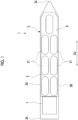
- a ship 1 of an embodiment of the present disclosure carries liquefied carbon dioxide or various liquefied gases including liquefied carbon dioxide. As shown in Figs. 1 and 2 , the ship 1 includes at least a hull 2, a tank 21, and a loading pipe 30. In this embodiment, a case of carrying liquefied carbon dioxide will be described as an example.
- the hull 2 has a pair of broadsides 3A and 3B forming an outer shell thereof, a ship bottom (not shown), and an exposure deck 5.
- the broadsides 3A and 3B are provided with a pair of broadside outer plates forming the left and right broadsides respectively.
- the ship bottom (not shown) is provided with a ship bottom outer plate connecting the broadsides 3A and 3B. Due to the pair of broadsides 3A and 3B and the ship bottom (not shown), the outer shell of the hull 2 has a U-shape in a cross-section orthogonal to a bow-stern direction Da.
- the exposure deck 5 is an all-deck that is exposed to the outside.
- a superstructure 7 having an accommodation space is formed on the exposure deck 5 on the stern 2b side.
- a tank system storage compartment (a hold) 8 is formed on the bow 2a side with respect to the superstructure (the accommodation space) 7.
- the tank system storage compartment 8 is a closed compartment that is recessed toward the ship bottom (not shown) below the exposure deck 5 and protrudes upward or has the exposure deck 5 as a ceiling.
- a plurality of tanks 21 are provided in the tank system storage compartment 8.
- a total of seven tanks 21 are provided in the tank system storage compartment 8.
- the layout and the number of tanks 21 installed in the tank system storage compartment 8 are not limited in any way.
- each tank 21 has, for example, a cylindrical shape extending in the horizontal direction (specifically, the bow-stern direction).
- the tank 21 contains liquefied carbon dioxide L inside.
- the tank 21 is not limited to a cylindrical shape and may have a spherical shape.
- the loading pipe 30 loads the liquefied carbon dioxide L, which is supplied from the outside of the ship, such as a liquefied carbon dioxide supply facility on land or a bunker ship, into the tank 21.
- the loading pipe 30 includes a transport pipe 31, an upper loading pipe 32, a lower loading pipe 33, a first on-off valve 34, a second on-off valve 35, and a spray pipe 38.
- the loading pipe 30 has a connection part 31j provided at a bunker station or the like and connected to the outside of the ship.
- the connection part 31j has, for example, a flange or the like, and is provided on at least one (for example, the broadside 3A) of the broadsides 3A and 3B.
- the loading pipe 30 is mainly provided in the hull 2.
- the upper loading pipe 32 branches off from the transport pipe 31 and reaches the inside of the tank 21.
- the upper loading pipe 32 of this embodiment extends downward in a ship height direction (hereinafter referred to as an up-down direction Dv) from the transport pipe 31.
- An opening 32a formed at a lower end of the upper loading pipe 32 is located at an upper portion in the tank 21.
- the upper portion in the tank 21 means a region in the tank 21 above the center of the tank 21 in the up-down direction Dv.
- the opening 32a of the upper loading pipe 32 may be located at a height equal to or higher than a height Ha when a liquid level Lf of the liquefied carbon dioxide L is at a height corresponding to, for example, 900 of the volume of the tank 21 in the up-down direction Dv.
- the upper loading pipe 32 supplies the liquefied carbon dioxide L into the tank 21 from the opening 32a provided at the upper portion in the tank 21.
- the lower loading pipe 33 branches off from the transport pipe 31 and reaches the inside of the tank 21, similar to the upper loading pipe 32.
- the lower loading pipe 33 of this embodiment extends downward in the up-down direction Dv from the transport pipe 31.
- An opening 33a formed at a lower end of the lower loading pipe 33 is located at a lower portion in the tank 21.
- the lower portion in the tank 21 means a region in the tank 21 below the center of the tank 21 in the up-down direction Dv.
- the opening 33a of the lower loading pipe 33 may be located at a height equal to or lower than a height Hb when the liquid level Lf of the liquefied carbon dioxide L is at a height corresponding to, for example, 10% of the volume of the tank 21 in the up-down direction Dv.
- the lower loading pipe 33 supplies the liquefied carbon dioxide L into the tank 21 from the opening 33a provided at the lower portion in the tank 21.
- the first on-off valve 34 is provided in the upper loading pipe 32.
- the first on-off valve 34 opens and closes the flow path in the upper loading pipe 32.
- the second on-off valve 35 is provided in the lower loading pipe 33.
- the second on-off valve 35 opens and closes the flow path in the lower loading pipe 33.
- Each of the first on-off valve 34 and the second on-off valve 35 can be switched between an opened state and a closed state, based on a control signal that is output from a control device 60 (described later).
- the spray pipe 38 branches off from the transport pipe 31 and reaches the inside of the tank 21.
- the spray pipe 38 has a plurality of injection holes (not shown).
- the injection holes of the spray pipe 38 exemplified in this embodiment are disposed on the lower side with respect to the opening 32a of the upper loading pipe 32 and the lower side with respect to the opening 33a of the lower loading pipe 33 in the up-down direction Dv.
- the spray pipe 38 injects the liquefied carbon dioxide L that is supplied through the transport pipe 31 into the tank 21 from the plurality of injection holes.
- the spray pipe 38 is provided with an on-off valve 39 for opening and closing the flow path from the transport pipe 31 to the spray pipe 38 on the side close to the transport pipe 31.
- the on-off valve 39 can be switched between an opened state and a closed state, based on a control signal that is output from the control device 60 (described later).
- the ship 1 further includes a liquid level detection unit 51, a pressure detection unit 52, and the control device 60.
- the liquid level detection unit 51 detects the liquid level Lf of the liquefied carbon dioxide L that is stored in the tank 21.
- the liquid level detection unit 51 outputs a detection signal of the detected liquid level Lf to the control device 60.
- the pressure detection unit 52 detects a pressure P of the liquefied carbon dioxide L in the loading pipe 30.
- the pressure detection unit 52 is provided, for example, at a top portion 30t, which is the highest position of the loading pipe 30.
- the pressure detection unit 52 detects the pressure P of the liquefied carbon dioxide L in the loading pipe 30 at the top portion 30t.
- the pressure detection unit 52 outputs a detection signal of the detected pressure P to the control device 60.
- the control device 60 controls the opening/closing operations of the first on-off valve 34 and the second on-off valve 35, based on the liquid level Lf of the liquefied carbon dioxide L in the tank 21, which is detected by the liquid level detection unit 51, when the liquefied carbon dioxide L is loaded into the tank 21.
- the control device 60 is a computer that includes a CPU 61 (Central Processing Unit), a ROM 62 (Read Only Memory), a RAM 63 (Random Access Memory), an HDD 64 (Hard Disk Drive), and a signal receiving module 65.
- the detection signal from the liquid level detection unit 51 and the detection signal from the pressure detection unit 52 are input to the signal receiving module 65.
- the control device 60 realizes a functional configuration of each of a signal input unit 70, an on-off valve control unit 71, a liquid level determination unit 72, a pressure determination unit 73, and an output unit 74 by executing, for example, a program stored in the own device in advance by the CPU 61.
- the signal input unit 70 receives the detection signal from the liquid level detection unit 51 and the detection signal from the pressure detection unit 52 by using the signal receiving module 65.
- the liquid level determination unit 72 determines whether or not the liquid level Lf of the liquefied carbon dioxide L in the tank 21 detected by the liquid level detection unit 51 has reached a switching level Ls (refer to Figs. 2 and 3 ) set in advance to be higher than the opening 33a of the lower loading pipe 33.
- a switching level Ls for example, the liquid level Lf in the range where the pressure P of the liquefied carbon dioxide L in the loading pipe 30 at the top portion 30t becomes higher than the triple point pressure of the liquefied carbon dioxide L when only the second on-off valve 35 of the lower loading pipe 33 is made be in an opened state is set.
- the switching level Ls a lower limit or the liquid level Lf slightly higher than the lower limit, of the liquid level Lf in the range where the pressure P of the liquefied carbon dioxide L in the loading pipe 30 at the top portion 30t becomes higher than the triple point pressure of the liquefied carbon dioxide L, may be set.
- the switching level Ls can be obtained by, for example, an experiment, simulation, calculation, or the like.
- the pressure determination unit 73 determines whether or not the pressure P of the liquefied carbon dioxide L detected by the pressure detection unit 52 has been lowered to a pressure equal to or lower than a reference pressure Ps determined in advance.
- the reference pressure Ps is the triple point pressure of the liquefied carbon dioxide L, or a pressure higher than the triple point pressure.
- the on-off valve control unit 71 controls the opening/closing operations of the first on-off valve 34, the second on-off valve 35, and the on-off valve 39.
- the on-off valve control unit 71 makes the on-off valve 39 be in an opened state and the first on-off valve 34 and the second on-off valve 35 be in a closed state, prior to the loading of the liquefied carbon dioxide L into the tank 21. At the time of the start of the loading of the liquefied carbon dioxide L into the tank 21, the on-off valve control unit 71 makes the on-off valve 39 be in a closed state and the first on-off valve 34 be in an opened state.
- the on-off valve control unit 71 makes the first on-off valve 34 be in a closed state and the second on-off valve 35 be in an opened state, in a case where the liquid level determination unit 72 determines that the liquid level Lf of the liquefied carbon dioxide L detected by the liquid level detection unit 51 has reached the switching level Ls.
- the on-off valve control unit 71 outputs a control signal for opening and closing the first on-off valve 34 and the second on-off valve 35 to the first on-off valve 34 and the second on-off valve 35 through the output unit 74.
- the on-off valve control unit 71 makes the first on-off valve 34 be in an opened state, in a case where the pressure of the liquefied carbon dioxide L detected by the pressure detection unit 52 becomes equal to or lower than the reference pressure Ps determined in advance, when the second on-off valve 35 is made be in an opened state.
- a method S10 of loading the liquefied carbon dioxide L into the ship 1 includes a step S11 of loading the liquefied carbon dioxide through the upper loading pipe, and a step S12 of loading the liquefied carbon dioxide through the lower loading pipe.
- step S11 of loading the liquefied carbon dioxide through the upper loading pipe first, only the on-off valve 39 among the first on-off valve 34, the second on-off valve 35, and the on-off valve 39 is made be in an opened state. Then, as shown in Fig. 4 , the liquefied carbon dioxide L is injected from the spray pipe 38 into the tank. In this way, the inside of the tank 21 is cooled, the pressure in the tank 21 is lowered, and more liquefied carbon dioxide L can be loaded.
- the on-off valve 39 is made be in a closed state and the first on-off valve 34 is made be in an opened state.
- the liquefied carbon dioxide L is loaded into the tank 21 through the upper loading pipe 32.
- the upper loading pipe 32 is open to the upper portion in the tank 21. Therefore, the liquefied carbon dioxide L is discharged to a gas phase in the tank 21 from the opening 32a of the upper loading pipe 32.
- a height difference ⁇ h1 from the top portion 30t which is located at the highest position of the loading pipe 30, is smaller than a height difference ⁇ h2 between the opening 33a of the lower loading pipe 33, which is open to the lower portion in the tank 21, and the top portion 30t. Therefore, it is possible to suppress a decrease in the pressure of the liquefied carbon dioxide L in the top portion 30t of the loading pipe 30 regardless of the position of the liquid level Lf of the liquefied carbon dioxide L.
- the processing transitions to the step S12 of loading the liquefied carbon dioxide through the lower loading pipe.
- the first on-off valve 34 is made be in a closed state and the second on-off valve 35 is made be in an opened state. In this way, as shown in Fig. 2 , the liquefied carbon dioxide L is loaded into the tank 21 through the lower loading pipe 33.
- the liquefied carbon dioxide L is stored to a level higher than the opening 33a of the lower loading pipe 33 (specifically, a level higher than the switching level Ls). Therefore, a pressure according to the height of the liquid level Lf (specifically, the switching level Ls or higher) of the liquefied carbon dioxide L stored in the tank 21 is applied to the liquefied carbon dioxide L in the lower loading pipe 33. In this way, the pressure of the liquefied carbon dioxide L in the top portion 30t of the loading pipe 30 is increased.
- the control device 60 causes the on-off valve control unit 71 to make the on-off valve 39 of the spray pipe 38 be in an opened state (step S21). Then, the liquefied carbon dioxide L that is supplied from the outside of the ship is injected into the tank 21 from the spray pipe 38, and the pressure in the tank 21 is lowered.
- control device 60 causes the on-off valve control unit 71 to make the on-off valve 39 be in a closed state and the first on-off valve 34 be in an opened state (step S22).
- the liquefied carbon dioxide L which is supplied from the outside of the ship, is supplied from the upper portion in the tank 21 through the transport pipe 31 and the upper loading pipe 32. In this way, the "step S11 of loading the liquefied carbon dioxide through the upper loading pipe" is executed.
- the liquid level determination unit 72 determines whether or not the liquid level Lf of the liquefied carbon dioxide L detected by the liquid level detection unit 51 has reached the switching level Ls set to be higher than the opening 33a of the lower loading pipe 33 (step S23). As a result of this determination, in a case where it is determined that the liquid level Lf has not reached the switching level Ls, the processing of step S23 is repeated at time intervals determined in advance. On the other hand, in a case where it is determined that the liquid level Lf has reached the switching level Ls, the processing proceeds to step S24.
- step S24 the on-off valve control unit 71 makes the first on-off valve 34 be in a closed state and the second on-off valve 35 be in an opened state. In this way, the supply of the liquefied carbon dioxide L to the tank 21 through the upper loading pipe 32 is stopped. Further, the supply of the liquefied carbon dioxide L to the tank 21 through the lower loading pipe 33 is started. In this way, the "step S12 of loading the liquefied carbon dioxide through the lower loading pipe" is executed.
- the pressure determination unit 73 determines whether or not the pressure P detected by the pressure detection unit 52, that is, the pressure P of the liquefied carbon dioxide L in the top portion 30t of the loading pipe 30 has been lowered to a pressure equal to or lower than the reference pressure Ps determined in advance (step S25). As a result, in a case where it is determined that the pressure of the liquefied carbon dioxide L has reached the reference pressure Ps, the processing proceeds to step S26.
- step S26 the on-off valve control unit 71 operates the second on-off valve 35 toward a closed state and the first on-off valve 34 toward an opened state.
- the second on-off valve 35 may be operated to a fully-closed state in a short time or may be gradually closed, such as being stepwise closed for each the opening degree set in advance, for example.
- the first on-off valve 34 may be operated to a fully-opened state in a short time or may be gradually opened, such as being stepwise opened for each opening degree determined in advance, for example.
- the first on-off valve 34 is operated in an open direction. Then, as shown in Fig. 3 , the liquefied carbon dioxide L is supplied into the tank 21 from the upper loading pipe 32. At this time, the opening 32a of the upper loading pipe 32 is disposed in the gas phase above the liquid level Lf of the liquefied carbon dioxide L loaded in the tank 21.
- the pressure of the gas phase (the operating pressure of the tank 21) is set to be higher than the reference pressure Ps. Therefore, the pressure of the liquefied carbon dioxide L in the top portion 30t of the loading pipe 30 increases.
- the pressure determination unit 73 determines whether or not the pressure of the liquefied carbon dioxide L in the top portion 30t of the loading pipe 30, which is detected by the pressure detection unit 52, has been returned to a return pressure Pt determined in advance (Pt > Ps) (Step S27). As a result of this determination, in a case where it is determined that the pressure of the liquefied carbon dioxide L has not reached the return pressure Pt, the loading of the liquefied carbon dioxide L from the upper loading pipe 32 is continued.
- step S27 it is determined that the pressure of the liquefied carbon dioxide L has reached the return pressure Pt, the on-off valve control unit 71 makes the first on-off valve 34 be in a closed state and the second on-off valve 35 be in an opened state (step S28). In this way, the liquefied carbon dioxide L returns to a state of being supplied into the tank 21 from the lower loading pipe 33.
- the on-off valve control unit 71 closes both the first on-off valve 34 and the second on-off valve 35 and ends the loading of the liquefied carbon dioxide L.
- the ship 1 of the above embodiment includes the upper loading pipe 32 that is open to the upper portion in the tank 21, the lower loading pipe 33 that is open to the lower portion in the tank 21, the first on-off valve 34 provided in the upper loading pipe 32, and the second on-off valve 35 provided in the lower loading pipe 33.
- the first on-off valve 34 when the first on-off valve 34 is made be in an opened state, the liquefied carbon dioxide L that is supplied from the outside of the ship 1 is supplied from the upper portion of the tank 21 through the transport pipe 31 and the upper loading pipe 32. Further, when the second on-off valve 35 is made be in an opened state, the liquefied carbon dioxide L that is supplied from the outside of the ship is supplied from the lower portion of the tank 21 through the transport pipe 31 and the lower loading pipe 33.
- the opening 32a of the upper loading pipe 32 is located at the upper portion in the tank 21, the height difference from the top portion 30t that is at the highest position in the loading pipe 30 is smaller than that in the opening 33a of the lower loading pipe 33 that is located at the lower portion in the tank 21, Therefore, when the liquefied carbon dioxide L is loaded by the upper loading pipe 32, it is possible to suppress a decrease in the pressure P of the liquefied carbon dioxide L at the highest position in the loading pipe 30 regardless of the liquid level Lf.
- the opening 33a of the lower loading pipe 33 is located at the lower portion in the tank 21, if the liquefied carbon dioxide L is stored to a level higher than the opening 33a of the lower loading pipe 33, a pressure according to the height of the liquid level Lf of the liquefied carbon dioxide L stored in the tank 21 is applied to the liquefied carbon dioxide L in the lower loading pipe 33. Then, if the liquid level Lf reaches a position where due to a rise of the liquid level Lf, an ambient pressure of the opening 33a becomes higher than the gas phase in the tank 21, it is possible to make the liquefied carbon dioxide L flowing into the tank 21 from the opening 33a be in a pressurized state (in other words, a sub-cool state). Therefore, it is possible to suppress the occurrence of flash evaporation of the liquefied carbon dioxide L flowing into the tank 21.
- the ship 1 of the above embodiment further includes the control device 60 for controlling the opening/closing operations of the first on-off valve 34 and the second on-off valve 35, based on the liquid level Lf of the liquefied carbon dioxide L in the tank 21, in a case where the liquefied carbon dioxide L is loaded into the tank 21.
- a configuration is made such that the control device 60 makes the second on-off valve 35 be in an opened state in a case where the liquid level Lf of the liquefied carbon dioxide L that is detected by the liquid level detection unit 51 reaches the switching level Ls set to be higher than the opening 33a of the lower loading pipe 33.
- control device 60 By such control of the control device 60, it is possible to load the liquefied carbon dioxide L into the tank 21 through the upper loading pipe 32 by making the first on-off valve 34 be in an opened state until the liquid level Lf of the liquefied carbon dioxide L in the tank 21 reaches the set switching level Ls. Since the upper loading pipe 32 is open to the upper portion in the tank 21, it is possible to perform the loading of the liquefied carbon dioxide L in a state of suppressing a decrease in the pressure of the liquefied carbon dioxide L at the highest position of the loading pipe 30.
- the control device 60 it is possible to load the liquefied carbon dioxide L into the tank 21 through the lower loading pipe 33 by making the second on-off valve 35 be in an opened state in a case where the liquid level Lf of the liquefied carbon dioxide L in the tank 21 reaches the switching level Ls.
- a pressure according to the height of the liquid level Lf of the liquefied carbon dioxide L stored in the tank 21, that is, the liquid level Lf equal to or higher than the switching level Ls is applied to the liquefied carbon dioxide L in the lower loading pipe 33. In this way, it is possible to perform the loading of the liquefied carbon dioxide L in a state where the pressure of the liquefied carbon dioxide L at the highest position of the loading pipe 30 is increased.
- a configuration is made such that the control device 60 makes the first on-off valve 34 be in an opened state in a case where the pressure P of the liquefied carbon dioxide L that is detected by the pressure detection unit 52 is equal to or lower than the reference pressure Ps determined in advance, when the second on-off valve 35 is in an opened state.
- the first on-off valve 34 be in an opened state in a case where the pressure P of the liquefied carbon dioxide L in the loading pipe 30 is lowered to a pressure equal to or lower than the reference pressure Ps in a state where the second on-off valve 35 is made be in an opened state and the liquefied carbon dioxide L is loaded into the tank 21 through the lower loading pipe 33. Since the upper loading pipe 32 is open to the upper portion in the tank 21, it is possible to make the height difference from the highest position of the loading pipe 30 small as compared with when the liquefied carbon dioxide L is loaded through the lower loading pipe 33. In this way, it becomes possible to increase the pressure of the liquefied carbon dioxide L at the highest position of the loading pipe 30.
- the first on-off valve 34 is made be in an opened state and the liquefied carbon dioxide L is loaded into the tank 21 through the upper loading pipe 32. Since the upper loading pipe 32 is open to the upper portion in the tank 21, it is possible to perform the loading of the liquefied carbon dioxide L in a state of suppressing a decrease in the pressure of the liquefied carbon dioxide L at the highest position of the loading pipe 30.
- the second on-off valve 35 is made be in an opened state and the liquefied carbon dioxide L is loaded into the tank 21 through the lower loading pipe 33.
- the liquefied carbon dioxide L is stored to a level higher than the opening of the lower loading pipe 33. Therefore, a pressure according to the height of the liquid level Lf of the liquefied carbon dioxide L stored in the tank 21 can be applied to the liquefied carbon dioxide L in the lower loading pipe 33. In this way, flash evaporation of the liquefied carbon dioxide L that has flowed into the tank 21 can be suppressed.
- the lower loading pipe 33 is provided so as to extend downward from the top portion of the tank 21 into the tank 21.
- the lower loading pipe 33 is provided so as to extend downward from the top portion of the tank 21 into the tank 21.
- a lower loading pipe 33B may be provided so as to wrap around from the upper side to the lower side of the tank 21, and an end portion of the lower loading pipe 33B may be connected to a lower end 21b of the tank 21. Even with such a configuration, the opening 33a of the lower loading pipe 33B can be located at the lower portion in the tank 21.
- the processing procedure in the method S10 of loading the liquefied carbon dioxide L into the ship 1 and the control device 60 for executing the method S10 of loading the liquefied carbon dioxide L into the ship 1 are shown.
- the procedure can be appropriately changed in order.
- the liquefied carbon dioxide L is injected from the spray pipe 38 into the tank 21.
- the injection of the liquefied carbon dioxide L may be omitted.
- the ships 1 and the method of loading liquefied carbon dioxide into the ship 1 described in the embodiment are grasped as follows, for example.
- the liquefied carbon dioxide L that is supplied from the outside of the ship is supplied from the upper portion in the tank 21 through the transport pipe 31 and the upper loading pipe 32. Further, when the second on-off valve 35 is opened, the liquefied carbon dioxide L that is supplied from the outside of the ship is supplied from the lower portion in the tank 21 through the transport pipe 31 and the lower loading pipe 33.
- the height difference from the highest position in the loading pipe 30 is small as compared with that in the lower loading pipe 33 that is open to the lower portion in the tank 21. In this way, it is possible to suppress a decrease in the pressure of the liquefied carbon dioxide L at the highest position of the loading pipe 30 regardless of the liquid level Lf in the tank 21.
- the lower loading pipe 33 is open to the lower portion in the tank 21, when the liquefied carbon dioxide L is stored to a level higher than the opening of the lower loading pipe 33, a pressure according to the height of the liquid level Lf of the liquefied carbon dioxide L stored in the tank 21 is applied to the liquefied carbon dioxide L in the lower loading pipe 33. In this way, the pressure of the liquefied carbon dioxide L at the highest position of the loading pipe 30 can be increased.
- the ship according to the above (1) further includes the control device 60 that controls the opening/closing operations of the first on-off valve 34 and the second on-off valve 35, based on the liquid level Lf of the liquefied carbon dioxide L in the tank 21, in a case where the liquefied carbon dioxide L is loaded into the tank 21.
- control device 60 controls the opening/closing operations of the first on-off valve 34 and the second on-off valve 35, based on the liquid level Lf of the liquefied carbon dioxide L in the tank 21, so that it is possible to automatically suppress a decrease in the pressure of the liquefied carbon dioxide L at the highest position in the loading pipe 30.
- the ship 1 of the above (2) further includes the liquid level detection unit 51 that detects the liquid level Lf of the liquefied carbon dioxide L that is stored in the tank 21, in which the control device 60 opens the first on-off valve 34 to load the liquefied carbon dioxide L into the tank 21 through the upper loading pipe 32, and opens the second on-off valve 35 to load the liquefied carbon dioxide L into the tank 21 through the lower loading pipe 33 in a case where the liquid level Lf of the liquefied carbon dioxide L that is detected by the liquid level detection unit 51 reaches the switching level Ls set to be higher than the opening 33a of the lower loading pipe 33.
- the first on-off valve 34 is opened and the liquefied carbon dioxide L is loaded into the tank 21 through the upper loading pipe 32 until the liquid level Lf of the liquefied carbon dioxide L in the tank 21 reaches the set switching level Ls. Since the upper loading pipe 32 is open to the upper portion in the tank 21, the loading of the liquefied carbon dioxide L can be performed in a state of suppressing a decrease in the pressure of the liquefied carbon dioxide L at the highest position in the loading pipe 30.
- the control of the control device 60 when the liquid level Lf of the liquefied carbon dioxide L in the tank 21 has reached the switching level Ls set to be higher than the opening 33a of the lower loading pipe 33, the second on-off valve 35 is opened and the liquefied carbon dioxide L is loaded into the tank 21 through the lower loading pipe 33.
- the liquefied carbon dioxide L is stored to a level higher than the opening of the lower loading pipe 33, and therefore, a pressure according to the height of the liquid level Lf of the liquefied carbon dioxide L stored in the tank 21 is applied to the liquefied carbon dioxide L in the lower loading pipe 33. In this way, it is possible to perform the loading of the liquefied carbon dioxide L in a state where the pressure of the liquefied carbon dioxide L at the highest position of the loading pipe 30 is increased.
- the ship 1 of the above (2) or (3) further includes the pressure detection unit 52 that detects the pressure of the liquefied carbon dioxide L in the loading pipe 30, in which the control device 60 opens the first on-off valve 34 in a case where the pressure P of the liquefied carbon dioxide L that is detected by the pressure detection unit 52 is equal to or lower than the reference pressure Ps determined in advance, in a state where the second on-off valve 35 is opened.
- the first on-off valve 34 is opened in a case where the pressure P of the liquefied carbon dioxide L in the loading pipe 30 has been lowered to a pressure equal to or lower than the reference pressure Ps in a state where the second on-off valve 35 is opened and the liquefied carbon dioxide L is loaded into the tank 21 through the lower loading pipe 33. Since the upper loading pipe 32 is open to the upper portion in the tank 21, it is possible to make the height difference from the highest position in the loading pipe 30 small as compared with when the liquefied carbon dioxide L is loaded through the lower loading pipe 33. In this way, it is possible to perform the loading of the liquefied carbon dioxide L in a state of suppressing a decrease in the pressure of the liquefied carbon dioxide L at the highest position in the loading pipe 30.
- the method of loading the liquefied carbon dioxide L into the ship 1 according to a fifth aspect is a method of loading the liquefied carbon dioxide L into the ship 1 of any one of the above (1) to (4) including: a step S11 of opening the first on-off valve 34 to load the liquefied carbon dioxide L into the tank 21 through the upper loading pipe 32, and a step S12 of closing the first on-off valve 34 and opening the second on-off valve 35 to load the liquefied carbon dioxide L into the tank 21 through the lower loading pipe 33, after the liquid level Lf of the liquefied carbon dioxide L in the tank 21 has reached the switching level Ls set to be higher than the opening 33a of the lower loading pipe 33.
- the first on-off valve 34 is opened and the liquefied carbon dioxide L is loaded into the tank 21 through the upper loading pipe 32. Since the upper loading pipe 32 is open to the upper portion in the tank 21, the loading of the liquefied carbon dioxide L can be performed in a state of suppressing a decrease in the pressure of the liquefied carbon dioxide L at the highest position in the loading pipe 30.
- the second on-off valve 35 is opened and the liquefied carbon dioxide L is loaded into the tank 21 through the lower loading pipe 33.
- the liquefied carbon dioxide L is stored to a level higher than the opening of the lower loading pipe 33, and therefore, a pressure according to the height of the liquid level Lf of the liquefied carbon dioxide L stored in the tank 21 is applied to the liquefied carbon dioxide L in the lower loading pipe 33. In this way, it is possible to perform the loading of the liquefied carbon dioxide L in a state where the pressure of the liquefied carbon dioxide L at the highest position of the loading pipe 30 is increased.
- the pressure of the liquefied carbon dioxide L at the highest position of the loading pipe 30 is restrained from approaching the triple point pressure. In this way, it is possible to suppress the generation of dry ice due to the solidification of the liquefied carbon dioxide L in the loading pipe 30. As a result, in a case where the liquefied carbon dioxide L is contained in the tank 21, it is possible to suppress the generation of dry ice in the loading pipe 30 and smoothly perform the operation of the tank 21.
Landscapes
- Engineering & Computer Science (AREA)
- Mechanical Engineering (AREA)
- Chemical & Material Sciences (AREA)
- Combustion & Propulsion (AREA)
- Ocean & Marine Engineering (AREA)
- General Engineering & Computer Science (AREA)
- Filling Or Discharging Of Gas Storage Vessels (AREA)
Description
- The present disclosure relates to a ship and a method of loading liquefied carbon dioxide into a ship.
- This application claims the right of priority based on
Japanese Patent Application No. 2019-228784 filed with the Japan Patent Office on December 19, 2019 -
PTL 1 discloses loading a liquefied gas such as LNG (Liquefied Natural Gas) into a tank through a pipe led from the vicinity of a top portion of the tank to the vicinity of a bottom portion of the tank. -
- [PTL 1]
Japanese Patent No. 5769445 - [PTL 2]
WO 2013/141453 A1 - [PTL 3]
WO 2015/002499 A1 - Incidentally, there is a demand for carrying liquefied carbon dioxide by using a tank as in
PTL 1. In the liquefied carbon dioxide, the pressure of a triple point (hereinafter referred to as triple point pressure) at which a gas phase, a liquid phase, and a solid phase coexist is higher than the triple point pressure of LNG or LPG. Therefore, the triple point pressure becomes close to the operating pressure of the tank. In a case where the liquefied carbon dioxide is contained in the tank, for the following reasons, there is a possibility that the liquefied carbon dioxide may be solidified to generate dry ice. - In the tank of
PTL 1, a lower end of a loading pipe, which is open in the tank, is disposed at a lower portion in the tank. With such disposition, the vicinity of the opening of the loading pipe is pressurized with an increase in liquid head. Therefore, flash evaporation of the liquefied gas discharged from the opening of the loading pipe can be suppressed. However, in a pipe top portion disposed at the highest position of the loading pipe, the pressure of the liquefied carbon dioxide inside is reduced by the amount corresponds to the height difference between the liquid level of the liquefied carbon dioxide in the tank and the pipe top portion with respect to the pressure of the liquefied carbon dioxide at the pipe lower end. - As a result, depending on a tank operating pressure, the pressure of the liquefied carbon dioxide becomes equal to or lower than the triple point pressure in the pipe top portion of the loading pipe where the pressure of the liquefied carbon dioxide becomes the lowest, or the liquefied carbon dioxide evaporates, and due to the evaporation latent heat thereof, the temperature of the liquefied carbon dioxide remaining without evaporating is lowered, so that there is a possibility that the liquefied carbon dioxide may be solidified in the pipe top portion of the loading pipe to generate dry ice.
- Then, in this manner, if dry ice is generated in the loading pipe, the flow of the liquefied carbon dioxide in the loading pipe is obstructed, so that there is a possibility that the operation of the tank may be affected.
- The present disclosure has been made in order to solve the above problem, and has an object to provide a ship and a method of loading liquefied carbon dioxide into a ship, in which it is possible to suppress the generation of dry ice in a loading pipe and smoothly perform the operation of a tank.
- In order to solve the above problem, a ship according to the present disclosure includes a hull, a tank, and a loading pipe. The hull has a pair of broadsides. The tank is provided in the hull. The tank is capable of storing liquefied carbon dioxide. The loading pipe loads liquefied carbon dioxide that is supplied from an outside of the ship into the tank. The loading pipe includes a transport pipe, an upper loading pipe, a lower loading pipe, a first on-off valve, and a second on-off valve. The transport pipe has a connection part for connection with the outside of the ship. The upper loading pipe branches off and extends from the transport pipe. The upper loading pipe is open to an upper portion in the tank. The lower loading pipe branches off and extends from the transport pipe. The lower loading pipe is open to a lower portion in the tank. The first on-off valve is provided in the upper loading pipe. The second on-off valve is provided in the lower loading pipe.
- A method of loading liquefied carbon dioxide into a ship according to the present disclosure is a method of loading liquefied carbon dioxide into the ship described above. The method of loading liquefied carbon dioxide into a ship includes: a step of opening the first on-off valve to load the liquefied carbon dioxide into the tank through the upper loading pipe; and a step of closing the first on-off valve and opening the second on-off valve to load the liquefied carbon dioxide into the tank through the lower loading pipe, after a liquid level of the liquefied carbon dioxide in the tank has reached a switching level set to be higher than an opening of the lower loading pipe.
- According to the ship and the method of loading liquefied carbon dioxide into a ship of the present disclosure, it is possible to suppress the generation of dry ice in a loading pipe and smoothly perform the operation of a tank.
-
-
Fig. 1 is a plan view showing a schematic configuration of a ship according to an embodiment of the present disclosure. -
Fig. 2 is a side sectional view showing a tank and a loading pipe provided in the ship according to the embodiment of the present disclosure. -
Fig. 3 is a side sectional view showing a state where liquefied carbon dioxide is loaded into a tank from an upper loading pipe, in the ship according to the embodiment of the present disclosure. -
Fig. 4 is a side sectional view showing a state where liquefied carbon dioxide is loaded into a tank from a spray pipe, in the ship according to the embodiment of the present disclosure. -
Fig. 5 is a diagram showing a hardware configuration of a control device provided on the ship according to the embodiment of the present disclosure. -
Fig. 6 is a functional block diagram of the control device provided on the ship according to the embodiment of the present disclosure. -
Fig. 7 is a flowchart showing procedure of a method of loading liquefied carbon dioxide into a ship according to the embodiment of the present disclosure. -
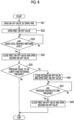
Fig. 8 is a flowchart showing procedure of processing that is performed by the control device in order to execute the method of loading liquefied carbon dioxide into a ship according to the embodiment of the present disclosure. -
Fig. 9 is a side sectional view showing a tank and a loading pipe provided in a ship according to a modification example the embodiment of the present disclosure. Description of Embodiments - Hereinafter, a ship according to an embodiment of the present disclosure will be described with reference to
Figs. 1 and2 . - A
ship 1 of an embodiment of the present disclosure carries liquefied carbon dioxide or various liquefied gases including liquefied carbon dioxide. As shown inFigs. 1 and2 , theship 1 includes at least a hull 2, atank 21, and aloading pipe 30. In this embodiment, a case of carrying liquefied carbon dioxide will be described as an example. - As shown in
Fig. 1 , the hull 2 has a pair ofbroadsides exposure deck 5. Thebroadsides broadsides broadsides exposure deck 5 is an all-deck that is exposed to the outside. In the hull 2, asuperstructure 7 having an accommodation space is formed on theexposure deck 5 on thestern 2b side. - In the hull 2, a tank system storage compartment (a hold) 8 is formed on the
bow 2a side with respect to the superstructure (the accommodation space) 7. The tank system storage compartment 8 is a closed compartment that is recessed toward the ship bottom (not shown) below theexposure deck 5 and protrudes upward or has theexposure deck 5 as a ceiling. - A plurality of
tanks 21 are provided in the tank system storage compartment 8. In thetank 21 in this embodiment, for example, a total of seventanks 21 are provided in the tank system storage compartment 8. The layout and the number oftanks 21 installed in the tank system storage compartment 8 are not limited in any way. In this embodiment, eachtank 21 has, for example, a cylindrical shape extending in the horizontal direction (specifically, the bow-stern direction). Thetank 21 contains liquefied carbon dioxide L inside. Thetank 21 is not limited to a cylindrical shape and may have a spherical shape. - The
loading pipe 30 loads the liquefied carbon dioxide L, which is supplied from the outside of the ship, such as a liquefied carbon dioxide supply facility on land or a bunker ship, into thetank 21. - As shown in
Fig. 2 , theloading pipe 30 includes atransport pipe 31, anupper loading pipe 32, alower loading pipe 33, a first on-offvalve 34, a second on-offvalve 35, and aspray pipe 38. - The
loading pipe 30 has aconnection part 31j provided at a bunker station or the like and connected to the outside of the ship. Theconnection part 31j has, for example, a flange or the like, and is provided on at least one (for example, thebroadside 3A) of thebroadsides connection part 31j. Theloading pipe 30 is mainly provided in the hull 2. - The
upper loading pipe 32 branches off from thetransport pipe 31 and reaches the inside of thetank 21. Theupper loading pipe 32 of this embodiment extends downward in a ship height direction (hereinafter referred to as an up-down direction Dv) from thetransport pipe 31. Anopening 32a formed at a lower end of theupper loading pipe 32 is located at an upper portion in thetank 21. Here, the upper portion in thetank 21 means a region in thetank 21 above the center of thetank 21 in the up-down direction Dv. Theopening 32a of theupper loading pipe 32 may be located at a height equal to or higher than a height Ha when a liquid level Lf of the liquefied carbon dioxide L is at a height corresponding to, for example, 900 of the volume of thetank 21 in the up-down direction Dv. As shown inFig. 3 , theupper loading pipe 32 supplies the liquefied carbon dioxide L into thetank 21 from theopening 32a provided at the upper portion in thetank 21. - The
lower loading pipe 33 branches off from thetransport pipe 31 and reaches the inside of thetank 21, similar to theupper loading pipe 32. Thelower loading pipe 33 of this embodiment extends downward in the up-down direction Dv from thetransport pipe 31. Anopening 33a formed at a lower end of thelower loading pipe 33 is located at a lower portion in thetank 21. Here, the lower portion in thetank 21 means a region in thetank 21 below the center of thetank 21 in the up-down direction Dv. Theopening 33a of thelower loading pipe 33 may be located at a height equal to or lower than a height Hb when the liquid level Lf of the liquefied carbon dioxide L is at a height corresponding to, for example, 10% of the volume of thetank 21 in the up-down direction Dv. As shown inFig. 2 , thelower loading pipe 33 supplies the liquefied carbon dioxide L into thetank 21 from theopening 33a provided at the lower portion in thetank 21. - The first on-off
valve 34 is provided in theupper loading pipe 32. The first on-offvalve 34 opens and closes the flow path in theupper loading pipe 32. - The second on-off
valve 35 is provided in thelower loading pipe 33. The second on-offvalve 35 opens and closes the flow path in thelower loading pipe 33. - Each of the first on-off
valve 34 and the second on-offvalve 35 can be switched between an opened state and a closed state, based on a control signal that is output from a control device 60 (described later). - The
spray pipe 38 branches off from thetransport pipe 31 and reaches the inside of thetank 21. Thespray pipe 38 has a plurality of injection holes (not shown). The injection holes of thespray pipe 38 exemplified in this embodiment are disposed on the lower side with respect to theopening 32a of theupper loading pipe 32 and the lower side with respect to theopening 33a of thelower loading pipe 33 in the up-down direction Dv. As shown inFig. 4 , thespray pipe 38 injects the liquefied carbon dioxide L that is supplied through thetransport pipe 31 into thetank 21 from the plurality of injection holes. Thespray pipe 38 is provided with an on-offvalve 39 for opening and closing the flow path from thetransport pipe 31 to thespray pipe 38 on the side close to thetransport pipe 31. The on-offvalve 39 can be switched between an opened state and a closed state, based on a control signal that is output from the control device 60 (described later). - The
ship 1 further includes a liquidlevel detection unit 51, apressure detection unit 52, and thecontrol device 60. - The liquid
level detection unit 51 detects the liquid level Lf of the liquefied carbon dioxide L that is stored in thetank 21. The liquidlevel detection unit 51 outputs a detection signal of the detected liquid level Lf to thecontrol device 60. - The
pressure detection unit 52 detects a pressure P of the liquefied carbon dioxide L in theloading pipe 30. Thepressure detection unit 52 is provided, for example, at atop portion 30t, which is the highest position of theloading pipe 30. Thepressure detection unit 52 detects the pressure P of the liquefied carbon dioxide L in theloading pipe 30 at thetop portion 30t. Thepressure detection unit 52 outputs a detection signal of the detected pressure P to thecontrol device 60. - The
control device 60 controls the opening/closing operations of the first on-offvalve 34 and the second on-offvalve 35, based on the liquid level Lf of the liquefied carbon dioxide L in thetank 21, which is detected by the liquidlevel detection unit 51, when the liquefied carbon dioxide L is loaded into thetank 21. - As shown in
Fig. 5 , thecontrol device 60 is a computer that includes a CPU 61 (Central Processing Unit), a ROM 62 (Read Only Memory), a RAM 63 (Random Access Memory), an HDD 64 (Hard Disk Drive), and asignal receiving module 65. The detection signal from the liquidlevel detection unit 51 and the detection signal from thepressure detection unit 52 are input to thesignal receiving module 65. - As shown in
Fig. 6 , thecontrol device 60 realizes a functional configuration of each of asignal input unit 70, an on-offvalve control unit 71, a liquidlevel determination unit 72, apressure determination unit 73, and anoutput unit 74 by executing, for example, a program stored in the own device in advance by theCPU 61. - The
signal input unit 70 receives the detection signal from the liquidlevel detection unit 51 and the detection signal from thepressure detection unit 52 by using thesignal receiving module 65. - The liquid
level determination unit 72 determines whether or not the liquid level Lf of the liquefied carbon dioxide L in thetank 21 detected by the liquidlevel detection unit 51 has reached a switching level Ls (refer toFigs. 2 and 3 ) set in advance to be higher than theopening 33a of thelower loading pipe 33. As the switching level Ls, for example, the liquid level Lf in the range where the pressure P of the liquefied carbon dioxide L in theloading pipe 30 at thetop portion 30t becomes higher than the triple point pressure of the liquefied carbon dioxide L when only the second on-offvalve 35 of thelower loading pipe 33 is made be in an opened state is set. Further, as the switching level Ls, a lower limit or the liquid level Lf slightly higher than the lower limit, of the liquid level Lf in the range where the pressure P of the liquefied carbon dioxide L in theloading pipe 30 at thetop portion 30t becomes higher than the triple point pressure of the liquefied carbon dioxide L, may be set. The switching level Ls can be obtained by, for example, an experiment, simulation, calculation, or the like. - The
pressure determination unit 73 determines whether or not the pressure P of the liquefied carbon dioxide L detected by thepressure detection unit 52 has been lowered to a pressure equal to or lower than a reference pressure Ps determined in advance. Here, the reference pressure Ps is the triple point pressure of the liquefied carbon dioxide L, or a pressure higher than the triple point pressure. - The on-off
valve control unit 71 controls the opening/closing operations of the first on-offvalve 34, the second on-offvalve 35, and the on-offvalve 39. - The on-off
valve control unit 71 makes the on-offvalve 39 be in an opened state and the first on-offvalve 34 and the second on-offvalve 35 be in a closed state, prior to the loading of the liquefied carbon dioxide L into thetank 21. At the time of the start of the loading of the liquefied carbon dioxide L into thetank 21, the on-offvalve control unit 71 makes the on-offvalve 39 be in a closed state and the first on-offvalve 34 be in an opened state. Further, after the start of the loading of the liquefied carbon dioxide L, the on-offvalve control unit 71 makes the first on-offvalve 34 be in a closed state and the second on-offvalve 35 be in an opened state, in a case where the liquidlevel determination unit 72 determines that the liquid level Lf of the liquefied carbon dioxide L detected by the liquidlevel detection unit 51 has reached the switching level Ls. The on-offvalve control unit 71 outputs a control signal for opening and closing the first on-offvalve 34 and the second on-offvalve 35 to the first on-offvalve 34 and the second on-offvalve 35 through theoutput unit 74. Further, the on-offvalve control unit 71 makes the first on-offvalve 34 be in an opened state, in a case where the pressure of the liquefied carbon dioxide L detected by thepressure detection unit 52 becomes equal to or lower than the reference pressure Ps determined in advance, when the second on-offvalve 35 is made be in an opened state. - As shown in
Fig. 7 , a method S10 of loading the liquefied carbon dioxide L into theship 1 according to this embodiment includes a step S11 of loading the liquefied carbon dioxide through the upper loading pipe, and a step S12 of loading the liquefied carbon dioxide through the lower loading pipe. - In the step S11 of loading the liquefied carbon dioxide through the upper loading pipe, first, only the on-off
valve 39 among the first on-offvalve 34, the second on-offvalve 35, and the on-offvalve 39 is made be in an opened state. Then, as shown inFig. 4 , the liquefied carbon dioxide L is injected from thespray pipe 38 into the tank. In this way, the inside of thetank 21 is cooled, the pressure in thetank 21 is lowered, and more liquefied carbon dioxide L can be loaded. - Thereafter, the on-off
valve 39 is made be in a closed state and the first on-offvalve 34 is made be in an opened state. In this way, as shown inFig. 3 , the liquefied carbon dioxide L is loaded into thetank 21 through theupper loading pipe 32. In this state, theupper loading pipe 32 is open to the upper portion in thetank 21. Therefore, the liquefied carbon dioxide L is discharged to a gas phase in thetank 21 from theopening 32a of theupper loading pipe 32. Further, a height difference Δh1 from thetop portion 30t, which is located at the highest position of theloading pipe 30, is smaller than a height difference Δh2 between theopening 33a of thelower loading pipe 33, which is open to the lower portion in thetank 21, and thetop portion 30t. Therefore, it is possible to suppress a decrease in the pressure of the liquefied carbon dioxide L in thetop portion 30t of theloading pipe 30 regardless of the position of the liquid level Lf of the liquefied carbon dioxide L. - After the liquefied carbon dioxide L is loaded into the
tank 21 through theupper loading pipe 32 and the liquid level Lf of the liquefied carbon dioxide L has reached the switching level Ls set to be higher than theopening 33a of thelower loading pipe 33, the processing transitions to the step S12 of loading the liquefied carbon dioxide through the lower loading pipe. In the step S12 of loading the liquefied carbon dioxide through the lower loading pipe, the first on-offvalve 34 is made be in a closed state and the second on-offvalve 35 is made be in an opened state. In this way, as shown inFig. 2 , the liquefied carbon dioxide L is loaded into thetank 21 through thelower loading pipe 33. In this state, the liquefied carbon dioxide L is stored to a level higher than theopening 33a of the lower loading pipe 33 (specifically, a level higher than the switching level Ls). Therefore, a pressure according to the height of the liquid level Lf (specifically, the switching level Ls or higher) of the liquefied carbon dioxide L stored in thetank 21 is applied to the liquefied carbon dioxide L in thelower loading pipe 33. In this way, the pressure of the liquefied carbon dioxide L in thetop portion 30t of theloading pipe 30 is increased. - Next, procedure of processing for automatically executing the method of loading the liquefied carbon dioxide into the ship under the control of the
control device 60 will be described. - As shown in
Fig. 8 , when the loading of the liquefied carbon dioxide L into thetank 21 is started, first, thecontrol device 60 causes the on-offvalve control unit 71 to make the on-offvalve 39 of thespray pipe 38 be in an opened state (step S21). Then, the liquefied carbon dioxide L that is supplied from the outside of the ship is injected into thetank 21 from thespray pipe 38, and the pressure in thetank 21 is lowered. - Subsequently, the
control device 60 causes the on-offvalve control unit 71 to make the on-offvalve 39 be in a closed state and the first on-offvalve 34 be in an opened state (step S22). Then, the liquefied carbon dioxide L, which is supplied from the outside of the ship, is supplied from the upper portion in thetank 21 through thetransport pipe 31 and theupper loading pipe 32. In this way, the "step S11 of loading the liquefied carbon dioxide through the upper loading pipe" is executed. - After the start of the loading of the liquefied carbon dioxide L, the liquid
level determination unit 72 determines whether or not the liquid level Lf of the liquefied carbon dioxide L detected by the liquidlevel detection unit 51 has reached the switching level Ls set to be higher than theopening 33a of the lower loading pipe 33 (step S23). As a result of this determination, in a case where it is determined that the liquid level Lf has not reached the switching level Ls, the processing of step S23 is repeated at time intervals determined in advance. On the other hand, in a case where it is determined that the liquid level Lf has reached the switching level Ls, the processing proceeds to step S24. - In step S24, the on-off
valve control unit 71 makes the first on-offvalve 34 be in a closed state and the second on-offvalve 35 be in an opened state. In this way, the supply of the liquefied carbon dioxide L to thetank 21 through theupper loading pipe 32 is stopped. Further, the supply of the liquefied carbon dioxide L to thetank 21 through thelower loading pipe 33 is started. In this way, the "step S12 of loading the liquefied carbon dioxide through the lower loading pipe" is executed. - After the start of the loading of the liquefied carbon dioxide L through the
lower loading pipe 33, thepressure determination unit 73 determines whether or not the pressure P detected by thepressure detection unit 52, that is, the pressure P of the liquefied carbon dioxide L in thetop portion 30t of theloading pipe 30 has been lowered to a pressure equal to or lower than the reference pressure Ps determined in advance (step S25). As a result, in a case where it is determined that the pressure of the liquefied carbon dioxide L has reached the reference pressure Ps, the processing proceeds to step S26. - In step S26, the on-off
valve control unit 71 operates the second on-offvalve 35 toward a closed state and the first on-offvalve 34 toward an opened state. At this time, the second on-offvalve 35 may be operated to a fully-closed state in a short time or may be gradually closed, such as being stepwise closed for each the opening degree set in advance, for example. Similarly, the first on-offvalve 34 may be operated to a fully-opened state in a short time or may be gradually opened, such as being stepwise opened for each opening degree determined in advance, for example. - In this way, for example, in a case where the pressure P of the liquefied carbon dioxide L is lowered to a pressure equal to or lower than the reference pressure Ps while the liquefied carbon dioxide L is being loaded through the
lower loading pipe 33, the first on-offvalve 34 is operated in an open direction. Then, as shown inFig. 3 , the liquefied carbon dioxide L is supplied into thetank 21 from theupper loading pipe 32. At this time, theopening 32a of theupper loading pipe 32 is disposed in the gas phase above the liquid level Lf of the liquefied carbon dioxide L loaded in thetank 21. The pressure of the gas phase (the operating pressure of the tank 21) is set to be higher than the reference pressure Ps. Therefore, the pressure of the liquefied carbon dioxide L in thetop portion 30t of theloading pipe 30 increases. - Thereafter, the
pressure determination unit 73 determines whether or not the pressure of the liquefied carbon dioxide L in thetop portion 30t of theloading pipe 30, which is detected by thepressure detection unit 52, has been returned to a return pressure Pt determined in advance (Pt > Ps) (Step S27). As a result of this determination, in a case where it is determined that the pressure of the liquefied carbon dioxide L has not reached the return pressure Pt, the loading of the liquefied carbon dioxide L from theupper loading pipe 32 is continued. On the other hand, in a case where in step S27, it is determined that the pressure of the liquefied carbon dioxide L has reached the return pressure Pt, the on-offvalve control unit 71 makes the first on-offvalve 34 be in a closed state and the second on-offvalve 35 be in an opened state (step S28). In this way, the liquefied carbon dioxide L returns to a state of being supplied into thetank 21 from thelower loading pipe 33. - In this way, the liquefied carbon dioxide L is loaded into the
tank 21, and when loading of a predetermined amount is completed, the on-offvalve control unit 71 closes both the first on-offvalve 34 and the second on-offvalve 35 and ends the loading of the liquefied carbon dioxide L. - The
ship 1 of the above embodiment includes theupper loading pipe 32 that is open to the upper portion in thetank 21, thelower loading pipe 33 that is open to the lower portion in thetank 21, the first on-offvalve 34 provided in theupper loading pipe 32, and the second on-offvalve 35 provided in thelower loading pipe 33. - In the
ship 1, when the first on-offvalve 34 is made be in an opened state, the liquefied carbon dioxide L that is supplied from the outside of theship 1 is supplied from the upper portion of thetank 21 through thetransport pipe 31 and theupper loading pipe 32. Further, when the second on-offvalve 35 is made be in an opened state, the liquefied carbon dioxide L that is supplied from the outside of the ship is supplied from the lower portion of thetank 21 through thetransport pipe 31 and thelower loading pipe 33. Since theopening 32a of theupper loading pipe 32 is located at the upper portion in thetank 21, the height difference from thetop portion 30t that is at the highest position in theloading pipe 30 is smaller than that in theopening 33a of thelower loading pipe 33 that is located at the lower portion in thetank 21, Therefore, when the liquefied carbon dioxide L is loaded by theupper loading pipe 32, it is possible to suppress a decrease in the pressure P of the liquefied carbon dioxide L at the highest position in theloading pipe 30 regardless of the liquid level Lf. - Further, since the
opening 33a of thelower loading pipe 33 is located at the lower portion in thetank 21, if the liquefied carbon dioxide L is stored to a level higher than theopening 33a of thelower loading pipe 33, a pressure according to the height of the liquid level Lf of the liquefied carbon dioxide L stored in thetank 21 is applied to the liquefied carbon dioxide L in thelower loading pipe 33. Then, if the liquid level Lf reaches a position where due to a rise of the liquid level Lf, an ambient pressure of theopening 33a becomes higher than the gas phase in thetank 21, it is possible to make the liquefied carbon dioxide L flowing into thetank 21 from theopening 33a be in a pressurized state (in other words, a sub-cool state). Therefore, it is possible to suppress the occurrence of flash evaporation of the liquefied carbon dioxide L flowing into thetank 21. - In this manner, by appropriately adjusting the open/closed states of the first on-off
valve 34 and the second on-offvalve 35 according to the storage state or the like of the liquefied carbon dioxide L in thetank 21, it is possible to suppress a decrease in the pressure of the liquefied carbon dioxide L at the highest position of theloading pipe 30. Therefore, it is possible to restrain the pressure of the liquefied carbon dioxide L at the highest position of theloading pipe 30 from approaching the triple point pressure. In this way, it becomes possible to suppress the generation of dry ice due to the solidification of the liquefied carbon dioxide L in theloading pipe 30 and smoothly perform the operation of thetank 21. - The
ship 1 of the above embodiment further includes thecontrol device 60 for controlling the opening/closing operations of the first on-offvalve 34 and the second on-offvalve 35, based on the liquid level Lf of the liquefied carbon dioxide L in thetank 21, in a case where the liquefied carbon dioxide L is loaded into thetank 21. - By controlling the opening/closing operations of the first on-off
valve 34 and the second on-offvalve 35 by thecontrol device 60, based on the liquid level Lf of the liquefied carbon dioxide L in thetank 21, it is possible to automatically suppress a decrease in the pressure of the liquefied carbon dioxide L at the highest position of theloading pipe 30. - Further, in the
ship 1 of the above embodiment, a configuration is made such that thecontrol device 60 makes the second on-offvalve 35 be in an opened state in a case where the liquid level Lf of the liquefied carbon dioxide L that is detected by the liquidlevel detection unit 51 reaches the switching level Ls set to be higher than theopening 33a of thelower loading pipe 33. - By such control of the
control device 60, it is possible to load the liquefied carbon dioxide L into thetank 21 through theupper loading pipe 32 by making the first on-offvalve 34 be in an opened state until the liquid level Lf of the liquefied carbon dioxide L in thetank 21 reaches the set switching level Ls. Since theupper loading pipe 32 is open to the upper portion in thetank 21, it is possible to perform the loading of the liquefied carbon dioxide L in a state of suppressing a decrease in the pressure of the liquefied carbon dioxide L at the highest position of theloading pipe 30. - Further, by such control of the
control device 60, it is possible to load the liquefied carbon dioxide L into thetank 21 through thelower loading pipe 33 by making the second on-offvalve 35 be in an opened state in a case where the liquid level Lf of the liquefied carbon dioxide L in thetank 21 reaches the switching level Ls. At this time, since the liquefied carbon dioxide L is stored to a level higher than the switching level Ls, a pressure according to the height of the liquid level Lf of the liquefied carbon dioxide L stored in thetank 21, that is, the liquid level Lf equal to or higher than the switching level Ls, is applied to the liquefied carbon dioxide L in thelower loading pipe 33. In this way, it is possible to perform the loading of the liquefied carbon dioxide L in a state where the pressure of the liquefied carbon dioxide L at the highest position of theloading pipe 30 is increased. - Further, in the
ship 1 of the above embodiment, a configuration is made such that thecontrol device 60 makes the first on-offvalve 34 be in an opened state in a case where the pressure P of the liquefied carbon dioxide L that is detected by thepressure detection unit 52 is equal to or lower than the reference pressure Ps determined in advance, when the second on-offvalve 35 is in an opened state. - In this way, it is possible to make the first on-off
valve 34 be in an opened state in a case where the pressure P of the liquefied carbon dioxide L in theloading pipe 30 is lowered to a pressure equal to or lower than the reference pressure Ps in a state where the second on-offvalve 35 is made be in an opened state and the liquefied carbon dioxide L is loaded into thetank 21 through thelower loading pipe 33. Since theupper loading pipe 32 is open to the upper portion in thetank 21, it is possible to make the height difference from the highest position of theloading pipe 30 small as compared with when the liquefied carbon dioxide L is loaded through thelower loading pipe 33. In this way, it becomes possible to increase the pressure of the liquefied carbon dioxide L at the highest position of theloading pipe 30. - In the method of loading the liquefied carbon dioxide L into the
ship 1 of the above embodiment, when loading the liquefied carbon dioxide L into thetank 21, first, the first on-offvalve 34 is made be in an opened state and the liquefied carbon dioxide L is loaded into thetank 21 through theupper loading pipe 32. Since theupper loading pipe 32 is open to the upper portion in thetank 21, it is possible to perform the loading of the liquefied carbon dioxide L in a state of suppressing a decrease in the pressure of the liquefied carbon dioxide L at the highest position of theloading pipe 30. Therefore, by restraining the pressure of the liquefied carbon dioxide L at the highest position of theloading pipe 30 from approaching the triple point pressure, it is possible to suppress the generation of dry ice due to the solidification of the liquefied carbon dioxide L in theloading pipe 30. Therefore, it becomes possible to smoothly perform the operation of thetank 21. - In the method of loading the liquefied carbon dioxide L, thereafter, the second on-off
valve 35 is made be in an opened state and the liquefied carbon dioxide L is loaded into thetank 21 through thelower loading pipe 33. In a state where the liquefied carbon dioxide L is loaded through thelower loading pipe 33, the liquefied carbon dioxide L is stored to a level higher than the opening of thelower loading pipe 33. Therefore, a pressure according to the height of the liquid level Lf of the liquefied carbon dioxide L stored in thetank 21 can be applied to the liquefied carbon dioxide L in thelower loading pipe 33. In this way, flash evaporation of the liquefied carbon dioxide L that has flowed into thetank 21 can be suppressed. - The embodiments of the present disclosure have been described in detail above with reference to the drawings. However, the specific configurations are not limited to the embodiments, and also include design changes or the like within a scope which does not deviate from the gist of the present disclosure.
- In the above embodiment, the
lower loading pipe 33 is provided so as to extend downward from the top portion of thetank 21 into thetank 21. However, there is no limitation thereto. - For example, as shown in
Fig. 9 , alower loading pipe 33B may be provided so as to wrap around from the upper side to the lower side of thetank 21, and an end portion of thelower loading pipe 33B may be connected to alower end 21b of thetank 21. Even with such a configuration, theopening 33a of thelower loading pipe 33B can be located at the lower portion in thetank 21. - Further, in the above embodiment, the processing procedure in the method S10 of loading the liquefied carbon dioxide L into the
ship 1 and thecontrol device 60 for executing the method S10 of loading the liquefied carbon dioxide L into theship 1 are shown. However, the procedure can be appropriately changed in order. - Further, in the above embodiment, the liquefied carbon dioxide L is injected from the
spray pipe 38 into thetank 21. However, the injection of the liquefied carbon dioxide L may be omitted. - The
ships 1 and the method of loading liquefied carbon dioxide into theship 1 described in the embodiment are grasped as follows, for example. - (1) The
ship 1 according to a first aspect includes the hull 2 having a pair ofbroadsides tank 21 that is provided in the hull 2 and is capable of storing the liquefied carbon dioxide L, and theloading pipe 30 that loads the liquefied carbon dioxide L that is supplied from the outside of the ship into thetank 21, in which theloading pipe 30 includes thetransport pipe 31 having theconnection part 31j for connection with the outside of the ship and extending into the hull 2, theupper loading pipe 32 that branches off and extends from thetransport pipe 31 and is open to the upper portion in thetank 21, thelower loading pipe 33 that branches off and extends from thetransport pipe 31 and is open to the lower portion in thetank 21, the first on-offvalve 34 provided in theupper loading pipe 32, and the second on-offvalve 35 provided in thelower loading pipe 33. - In the
ship 1, when the first on-offvalve 34 is opened, the liquefied carbon dioxide L that is supplied from the outside of the ship is supplied from the upper portion in thetank 21 through thetransport pipe 31 and theupper loading pipe 32. Further, when the second on-offvalve 35 is opened, the liquefied carbon dioxide L that is supplied from the outside of the ship is supplied from the lower portion in thetank 21 through thetransport pipe 31 and thelower loading pipe 33. - Since the
upper loading pipe 32 is open to the upper portion in thetank 21, the height difference from the highest position in theloading pipe 30 is small as compared with that in thelower loading pipe 33 that is open to the lower portion in thetank 21. In this way, it is possible to suppress a decrease in the pressure of the liquefied carbon dioxide L at the highest position of theloading pipe 30 regardless of the liquid level Lf in thetank 21. - Further, since the
lower loading pipe 33 is open to the lower portion in thetank 21, when the liquefied carbon dioxide L is stored to a level higher than the opening of thelower loading pipe 33, a pressure according to the height of the liquid level Lf of the liquefied carbon dioxide L stored in thetank 21 is applied to the liquefied carbon dioxide L in thelower loading pipe 33. In this way, the pressure of the liquefied carbon dioxide L at the highest position of theloading pipe 30 can be increased. - In this manner, by appropriately adjusting the opening and closing of the first on-off
valve 34 and the second on-offvalve 35 according to the storage situation or the like of the liquefied carbon dioxide L in thetank 21, it is possible to suppress a decrease in the pressure of the liquefied carbon dioxide L at the highest position in theloading pipe 30. Therefore, the pressure of the liquefied carbon dioxide L at the highest position of theloading pipe 30 can be restrained from approaching the triple point pressure. In this way, it is possible to suppress the generation of dry ice due to the solidification of the liquefied carbon dioxide L in theloading pipe 30. As a result, in a case where the liquefied carbon dioxide L is contained in thetank 21, it is possible to suppress the generation of dry ice in theloading pipe 30 and smoothly perform the operation of thetank 21. - (2) In the
ship 1 according to a second aspect, the ship according to the above (1) further includes thecontrol device 60 that controls the opening/closing operations of the first on-offvalve 34 and the second on-offvalve 35, based on the liquid level Lf of the liquefied carbon dioxide L in thetank 21, in a case where the liquefied carbon dioxide L is loaded into thetank 21. - In this way, the
control device 60 controls the opening/closing operations of the first on-offvalve 34 and the second on-offvalve 35, based on the liquid level Lf of the liquefied carbon dioxide L in thetank 21, so that it is possible to automatically suppress a decrease in the pressure of the liquefied carbon dioxide L at the highest position in theloading pipe 30. - (3) In the
ship 1 according to the above (3), theship 1 of the above (2) further includes the liquidlevel detection unit 51 that detects the liquid level Lf of the liquefied carbon dioxide L that is stored in thetank 21, in which thecontrol device 60 opens the first on-offvalve 34 to load the liquefied carbon dioxide L into thetank 21 through theupper loading pipe 32, and opens the second on-offvalve 35 to load the liquefied carbon dioxide L into thetank 21 through thelower loading pipe 33 in a case where the liquid level Lf of the liquefied carbon dioxide L that is detected by the liquidlevel detection unit 51 reaches the switching level Ls set to be higher than theopening 33a of thelower loading pipe 33. - In this way, by the control of the
control device 60, the first on-offvalve 34 is opened and the liquefied carbon dioxide L is loaded into thetank 21 through theupper loading pipe 32 until the liquid level Lf of the liquefied carbon dioxide L in thetank 21 reaches the set switching level Ls. Since theupper loading pipe 32 is open to the upper portion in thetank 21, the loading of the liquefied carbon dioxide L can be performed in a state of suppressing a decrease in the pressure of the liquefied carbon dioxide L at the highest position in theloading pipe 30. - Further, by the control of the
control device 60, when the liquid level Lf of the liquefied carbon dioxide L in thetank 21 has reached the switching level Ls set to be higher than theopening 33a of thelower loading pipe 33, the second on-offvalve 35 is opened and the liquefied carbon dioxide L is loaded into thetank 21 through thelower loading pipe 33. In this state, the liquefied carbon dioxide L is stored to a level higher than the opening of thelower loading pipe 33, and therefore, a pressure according to the height of the liquid level Lf of the liquefied carbon dioxide L stored in thetank 21 is applied to the liquefied carbon dioxide L in thelower loading pipe 33. In this way, it is possible to perform the loading of the liquefied carbon dioxide L in a state where the pressure of the liquefied carbon dioxide L at the highest position of theloading pipe 30 is increased. - (4) In the
ship 1 according to a fourth aspect, theship 1 of the above (2) or (3) further includes thepressure detection unit 52 that detects the pressure of the liquefied carbon dioxide L in theloading pipe 30, in which thecontrol device 60 opens the first on-offvalve 34 in a case where the pressure P of the liquefied carbon dioxide L that is detected by thepressure detection unit 52 is equal to or lower than the reference pressure Ps determined in advance, in a state where the second on-offvalve 35 is opened. - In this way, the first on-off
valve 34 is opened in a case where the pressure P of the liquefied carbon dioxide L in theloading pipe 30 has been lowered to a pressure equal to or lower than the reference pressure Ps in a state where the second on-offvalve 35 is opened and the liquefied carbon dioxide L is loaded into thetank 21 through thelower loading pipe 33. Since theupper loading pipe 32 is open to the upper portion in thetank 21, it is possible to make the height difference from the highest position in theloading pipe 30 small as compared with when the liquefied carbon dioxide L is loaded through thelower loading pipe 33. In this way, it is possible to perform the loading of the liquefied carbon dioxide L in a state of suppressing a decrease in the pressure of the liquefied carbon dioxide L at the highest position in theloading pipe 30. - (5) The method of loading the liquefied carbon dioxide L into the
ship 1 according to a fifth aspect is a method of loading the liquefied carbon dioxide L into theship 1 of any one of the above (1) to (4) including: a step S11 of opening the first on-offvalve 34 to load the liquefied carbon dioxide L into thetank 21 through theupper loading pipe 32, and a step S12 of closing the first on-offvalve 34 and opening the second on-offvalve 35 to load the liquefied carbon dioxide L into thetank 21 through thelower loading pipe 33, after the liquid level Lf of the liquefied carbon dioxide L in thetank 21 has reached the switching level Ls set to be higher than theopening 33a of thelower loading pipe 33. - In this way, when the liquefied carbon dioxide L is loaded into the
tank 21, first, the first on-offvalve 34 is opened and the liquefied carbon dioxide L is loaded into thetank 21 through theupper loading pipe 32. Since theupper loading pipe 32 is open to the upper portion in thetank 21, the loading of the liquefied carbon dioxide L can be performed in a state of suppressing a decrease in the pressure of the liquefied carbon dioxide L at the highest position in theloading pipe 30. - Thereafter, the second on-off
valve 35 is opened and the liquefied carbon dioxide L is loaded into thetank 21 through thelower loading pipe 33. In this state, the liquefied carbon dioxide L is stored to a level higher than the opening of thelower loading pipe 33, and therefore, a pressure according to the height of the liquid level Lf of the liquefied carbon dioxide L stored in thetank 21 is applied to the liquefied carbon dioxide L in thelower loading pipe 33. In this way, it is possible to perform the loading of the liquefied carbon dioxide L in a state where the pressure of the liquefied carbon dioxide L at the highest position of theloading pipe 30 is increased. - In this way, the pressure of the liquefied carbon dioxide L at the highest position of the
loading pipe 30 is restrained from approaching the triple point pressure. In this way, it is possible to suppress the generation of dry ice due to the solidification of the liquefied carbon dioxide L in theloading pipe 30. As a result, in a case where the liquefied carbon dioxide L is contained in thetank 21, it is possible to suppress the generation of dry ice in theloading pipe 30 and smoothly perform the operation of thetank 21. - According to the ship and the method of loading liquefied carbon dioxide into a ship of the present disclosure, it is possible to suppress the generation of dry ice in a loading pipe and smoothly perform the operation of a tank.
-
- 1: ship
- 2: hull
- 2a: bow
- 2b: stern
- 3A, 3B: broadside
- 5: exposure deck
- 7: superstructure
- 8: tank system storage compartment
- 21: tank
- 21b: lower end
- 30: loading pipe
- 30t: top portion
- 31: transport pipe
- 31j: connection part
- 32: upper loading pipe
- 32a: opening
- 33, 33B: lower loading pipe
- 33a: opening
- 34: first on-off valve
- 35: second on-off valve
- 38: spray pipe
- 39: on-off valve
- 51: liquid level detection unit
- 52: pressure detection unit
- 60: control device
- 61: CPU
- 62: ROM
- 63: RAM
- 64: HDD
- 65: signal receiving module
- 70: signal input unit
- 71: on-off valve control unit
- 72: liquid level determination unit
- 73: pressure determination unit
- 74: output unit
- L: liquefied carbon dioxide
- Lf: liquid level
- Ls: switching level
Claims (5)
- A ship (1) comprising:a hull (2) having a pair of broadsides (3A, 3B);a tank (21) that is provided in the hull (2) and is capable of storing liquefied carbon dioxide (L); anda loading pipe (30) that loads liquefied carbon dioxide (L) that is supplied from an outside of the ship (1) into the tank (21),wherein the loading pipe (30) includesa transport pipe (31) having a connection part (31j) for connection with the outside of the ship (1),an upper loading pipe (32) that branches off and extends from the transport pipe (31) and is open to an upper portion in the tank (21),a lower loading pipe (33) that branches off and extends from the transport pipe (31) and is open to a lower portion in the tank (21),a first on-off valve (34) provided in the upper loading pipe (32),a second on-off valve (35) provided in the lower loading pipe (33),a spray pipe (38) that branches off from the transport pipe (31) to reach inside the tank (21) and has a plurality of injection holes disposed on a lower side with respect to an opening (32a) of the upper loading pipe (32) and on an upper side with respect to an opening (33a) of the lower loading pipe (33), andan on-off valve (39) provided in the spray pipe (38).
- The ship (1) according to claim 1, further comprising:
a control device (60) that controls opening/closing operations of the first on-off valve (34) and the second on-off valve (35), based on a liquid level (Lf) of the liquefied carbon dioxide (L) in the tank (21), when the liquefied carbon dioxide (L) is loaded into the tank (21). - The ship (1) according to claim 2, further comprising:a liquid level detection unit (51) that detects the liquid level (Lf) of the liquefied carbon dioxide (L) that is stored in the tank (21),wherein the control device (60) opens the first on-off valve (34) to load the liquefied carbon dioxide (L) into the tank (21) through the upper loading pipe (32), and opens the second on-off valve (35) to load the liquefied carbon dioxide (L) into the tank (21) through the lower loading pipe (33) in a case where the liquid level (Lf) of the liquefied carbon dioxide (L) that is detected by the liquid level detection unit (51) reaches a switching level (Ls) set to be higher than the opening (33a) of the lower loading pipe (33).
- The ship (1) according to claim 2 or 3, further comprising:a pressure detection unit (52) that detects a pressure of the liquefied carbon dioxide (L) in the loading pipe (30),wherein the control device (60) opens the first on-off valve (34) in a case where the pressure of the liquefied carbon dioxide (L) that is detected by the pressure detection unit (52) becomes equal to or lower than a reference pressure (Ps) determined in advance, in a state where the second on-off valve (35) is opened.
- A method of loading liquefied carbon dioxide (L) into the ship (1) according to any one of claims 1 to 4, the method comprising:a step of opening the on-off valve (39) to inject the liquefied carbon dioxide (L) into the tank (21) from the spray pipe (38);a step of opening the first on-off valve (34) to load the liquefied carbon dioxide (L) into the tank (21) through the upper loading pipe (32); anda step of closing the first on-off valve (34) and opening the second on-off valve (35) to load the liquefied carbon dioxide (L) into the tank (21) through the lower loading pipe (33), after a liquid level (Lf) of the liquefied carbon dioxide (L) in the tank (21) has reached a switching level (Ls) set to be higher than the opening (33a) of the lower loading pipe (33).
Applications Claiming Priority (2)
| Application Number | Priority Date | Filing Date | Title |
|---|---|---|---|
| JP2019228784A JP7350647B2 (en) | 2019-12-19 | 2019-12-19 | How to load liquefied carbon dioxide on ships and ships |
| PCT/JP2020/033866 WO2021124619A1 (en) | 2019-12-19 | 2020-09-08 | Ship and method of loading liquefied carbon dioxide into ship |
Publications (3)
| Publication Number | Publication Date |
|---|---|
| EP4056459A1 EP4056459A1 (en) | 2022-09-14 |
| EP4056459A4 EP4056459A4 (en) | 2022-12-28 |
| EP4056459B1 true EP4056459B1 (en) | 2024-02-21 |
Family
ID=76431982
Family Applications (1)
| Application Number | Title | Priority Date | Filing Date |
|---|---|---|---|
| EP20901800.1A Active EP4056459B1 (en) | 2019-12-19 | 2020-09-08 | Ship and method of loading liquefied carbon dioxide into ship |
Country Status (8)
| Country | Link |
|---|---|
| EP (1) | EP4056459B1 (en) |
| JP (1) | JP7350647B2 (en) |
| KR (1) | KR102744965B1 (en) |
| CN (1) | CN114761317B (en) |
| AU (1) | AU2020404622B9 (en) |
| DK (1) | DK4056459T3 (en) |
| FI (1) | FI4056459T3 (en) |
| WO (1) | WO2021124619A1 (en) |
Families Citing this family (6)
| Publication number | Priority date | Publication date | Assignee | Title |
|---|---|---|---|---|
| EP4406823A4 (en) * | 2021-11-04 | 2024-11-27 | Mitsubishi Shipbuilding Co., Ltd. | Ship |
| JP7588621B2 (en) * | 2022-06-15 | 2024-11-22 | 三菱重工業株式会社 | Liquefied carbon dioxide discharge facility, floating body, and liquefied carbon dioxide discharge method |
| CN115199937B (en) * | 2022-07-25 | 2023-07-18 | 江南造船(集团)有限责任公司 | Carbon dioxide transport ship cabin pressure control method and system and carbon dioxide transport ship |
| JP7245949B1 (en) * | 2022-08-24 | 2023-03-24 | 三菱造船株式会社 | Liquefied carbon dioxide equipment, method for estimating generation status of dry ice |
| NO347928B1 (en) * | 2023-04-12 | 2024-05-13 | Azane Fuel Solutions As | A system for preventing pressure-driven liquid spillage |
| KR102884343B1 (en) * | 2023-05-02 | 2025-11-13 | 한화오션 주식회사 | Liquefied carbon dioxide unloading system and liquefied carbon dioxide unloading method preventing dry ice generation |
Family Cites Families (21)
| Publication number | Priority date | Publication date | Assignee | Title |
|---|---|---|---|---|
| US3962881A (en) * | 1974-02-19 | 1976-06-15 | Airco, Inc. | Liquefaction of a vapor utilizing refrigeration of LNG |
| JPS5769445U (en) | 1980-10-08 | 1982-04-26 | ||
| JPH04297392A (en) * | 1991-03-26 | 1992-10-21 | Mitsubishi Heavy Ind Ltd | Carbonic acid gas transport ship |
| TW359736B (en) * | 1997-06-20 | 1999-06-01 | Exxon Production Research Co | Systems for vehicular, land-based distribution of liquefied natural gas |
| JP4763915B2 (en) * | 2001-05-23 | 2011-08-31 | 三菱重工業株式会社 | Liquefied carbon dioxide storage / discharge device and liquefied carbon dioxide underwater injection system |
| JP2004125039A (en) * | 2002-10-01 | 2004-04-22 | Mitsubishi Heavy Ind Ltd | Co2 transporting method, fluid storing device, plug shooting device, plug recovering device, and fluid storing method |
| GB2416390B (en) * | 2004-07-16 | 2006-07-26 | Statoil Asa | LCD Offshore Transport System |
| GB0614250D0 (en) * | 2006-07-18 | 2006-08-30 | Ntnu Technology Transfer As | Apparatus and Methods for Natural Gas Transportation and Processing |
| JP2010196825A (en) * | 2009-02-25 | 2010-09-09 | Chugoku Electric Power Co Inc:The | Low temperature liquefied gas delivery device and low temperature liquefied gas delivery method |
| KR20100125624A (en) * | 2009-05-21 | 2010-12-01 | 대우조선해양 주식회사 | Low pressure prevention system for transfer tank of combined vessel carrying carbon dioxide and natural gas |
| CN201764248U (en) * | 2010-07-22 | 2011-03-16 | 陈新法 | Improved carbon dioxide filling device |
| JP5769445B2 (en) | 2011-02-25 | 2015-08-26 | 三菱重工業株式会社 | Surplus gas generation suppression method for liquefied natural gas storage / transport ship and liquefied natural gas storage / transport ship |
| KR101378995B1 (en) * | 2012-03-22 | 2014-04-02 | 삼성중공업 주식회사 | Carbon Dioxide Handling System And Method |
| KR101379954B1 (en) * | 2012-03-22 | 2014-03-28 | 삼성중공업 주식회사 | Carbon Dioxide Handling System and Method |
| KR20140067216A (en) * | 2012-11-26 | 2014-06-05 | 대우조선해양 주식회사 | Co2 carrying ship having buffer tank |
| KR101497420B1 (en) * | 2013-07-05 | 2015-03-03 | 삼성중공업 주식회사 | LNG transportation Apparatus for reducing Boil-Off Gas |
| WO2017000072A1 (en) * | 2015-06-29 | 2017-01-05 | Westport Power Inc. | Multi-vessel fluid storage and delivery system |
| KR101826687B1 (en) * | 2016-06-22 | 2018-02-07 | 대우조선해양 주식회사 | Cargo Tank Management System and Method of Liquefied Gas Carrier |
| JP6603969B2 (en) * | 2017-04-06 | 2019-11-13 | 三菱造船株式会社 | Ship |
| JP7034759B2 (en) * | 2018-02-23 | 2022-03-14 | 三菱重工マリンマシナリ株式会社 | Condensation system control method and condensate system and ships equipped with it |
| FR3082015B1 (en) * | 2018-05-31 | 2021-11-05 | Gaztransport Et Technigaz | METHOD FOR MANAGING THE FILLING LEVELS OF TANKS |
-
2019
- 2019-12-19 JP JP2019228784A patent/JP7350647B2/en active Active
-
2020
- 2020-09-08 AU AU2020404622A patent/AU2020404622B9/en active Active
- 2020-09-08 KR KR1020227019303A patent/KR102744965B1/en active Active
- 2020-09-08 FI FIEP20901800.1T patent/FI4056459T3/en active
- 2020-09-08 DK DK20901800.1T patent/DK4056459T3/en active
- 2020-09-08 WO PCT/JP2020/033866 patent/WO2021124619A1/en not_active Ceased
- 2020-09-08 CN CN202080085172.7A patent/CN114761317B/en active Active
- 2020-09-08 EP EP20901800.1A patent/EP4056459B1/en active Active
Also Published As
| Publication number | Publication date |
|---|---|
| EP4056459A4 (en) | 2022-12-28 |
| WO2021124619A1 (en) | 2021-06-24 |
| AU2020404622A1 (en) | 2022-06-23 |
| JP2021095051A (en) | 2021-06-24 |
| JP7350647B2 (en) | 2023-09-26 |
| FI4056459T3 (en) | 2024-04-24 |
| CN114761317A (en) | 2022-07-15 |
| AU2020404622B2 (en) | 2024-04-11 |
| CN114761317B (en) | 2024-04-09 |
| EP4056459A1 (en) | 2022-09-14 |
| DK4056459T3 (en) | 2024-03-04 |
| KR20220093214A (en) | 2022-07-05 |
| KR102744965B1 (en) | 2024-12-19 |
| AU2020404622B9 (en) | 2024-05-02 |
Similar Documents
| Publication | Publication Date | Title |
|---|---|---|
| AU2020404622B2 (en) | Ship and method of loading liquefied carbon dioxide into ship | |
| JP7221856B2 (en) | tank systems, ships | |
| KR20190111135A (en) | Ship | |
| JP7834076B2 (en) | Gas replacement method | |
| AU2020407675B2 (en) | Ship | |
| JP7561574B2 (en) | Floating body, method for loading liquefied carbon dioxide, and method for unloading liquefied carbon dioxide | |
| KR20220000431A (en) | Floating structure having hybrid cargo tank | |
| KR102903736B1 (en) | Method for regulating the pressure of a tank in a ship or vessel | |
| KR102808417B1 (en) | Fuel storage system for ship | |
| KR20090099367A (en) | Floating structure with propulsion device for propulsion and bow angle control and bow angle control method of the floating structure | |
| AU2021369256B2 (en) | Floating Structure | |
| WO2024202270A1 (en) | Liquefied carbon dioxide tank system and method for controlling liquefied carbon dioxide tank system | |
| EP4406823A1 (en) | Ship | |
| KR20250154138A (en) | Cargo transportation system | |
| KR20140014980A (en) | Cargo manifold appartus for lng carrier | |
| KR20120000972A (en) | Liquefied gas storage tank with safety valve | |
| KR20120000971A (en) | Liquefied gas storage tank with safety valve | |
| KR102448810B1 (en) | turning device | |
| KR20250148759A (en) | Liquefied gas storage tank | |
| KR102514082B1 (en) | Anti-rolling system for ship | |
| KR20240138137A (en) | Sloshing impact reduction control system for ship carrying liquid cargo | |
| KR20220004866A (en) | Apparatus and method for controlling pressure of lng tank | |
| KR20190058122A (en) | Semi-submersible ocean structure having lng storage tank |
Legal Events
| Date | Code | Title | Description |
|---|---|---|---|
| STAA | Information on the status of an ep patent application or granted ep patent |
Free format text: STATUS: THE INTERNATIONAL PUBLICATION HAS BEEN MADE |
|
| PUAI | Public reference made under article 153(3) epc to a published international application that has entered the european phase |
Free format text: ORIGINAL CODE: 0009012 |
|
| STAA | Information on the status of an ep patent application or granted ep patent |
Free format text: STATUS: REQUEST FOR EXAMINATION WAS MADE |
|
| 17P | Request for examination filed |
Effective date: 20220609 |
|
| AK | Designated contracting states |
Kind code of ref document: A1 Designated state(s): AL AT BE BG CH CY CZ DE DK EE ES FI FR GB GR HR HU IE IS IT LI LT LU LV MC MK MT NL NO PL PT RO RS SE SI SK SM TR |
|
| A4 | Supplementary search report drawn up and despatched |
Effective date: 20221130 |
|
| RIC1 | Information provided on ipc code assigned before grant |
Ipc: F17C 13/00 20060101ALI20221124BHEP Ipc: F17C 6/00 20060101ALI20221124BHEP Ipc: B63B 27/24 20060101ALI20221124BHEP Ipc: B63B 25/08 20060101AFI20221124BHEP |
|
| DAV | Request for validation of the european patent (deleted) | ||
| DAX | Request for extension of the european patent (deleted) | ||
| GRAP | Despatch of communication of intention to grant a patent |
Free format text: ORIGINAL CODE: EPIDOSNIGR1 |
|
| STAA | Information on the status of an ep patent application or granted ep patent |
Free format text: STATUS: GRANT OF PATENT IS INTENDED |
|
| INTG | Intention to grant announced |
Effective date: 20230918 |
|
| GRAS | Grant fee paid |
Free format text: ORIGINAL CODE: EPIDOSNIGR3 |
|
| GRAA | (expected) grant |
Free format text: ORIGINAL CODE: 0009210 |
|
| STAA | Information on the status of an ep patent application or granted ep patent |
Free format text: STATUS: THE PATENT HAS BEEN GRANTED |
|
| AK | Designated contracting states |
Kind code of ref document: B1 Designated state(s): AL AT BE BG CH CY CZ DE DK EE ES FI FR GB GR HR HU IE IS IT LI LT LU LV MC MK MT NL NO PL PT RO RS SE SI SK SM TR |
|
| REG | Reference to a national code |
Ref country code: GB Ref legal event code: FG4D |
|
| REG | Reference to a national code |
Ref country code: CH Ref legal event code: EP |
|
| REG | Reference to a national code |
Ref country code: DK Ref legal event code: T3 Effective date: 20240229 |
|
| REG | Reference to a national code |
Ref country code: IE Ref legal event code: FG4D |
|
| REG | Reference to a national code |
Ref country code: DE Ref legal event code: R096 Ref document number: 602020026234 Country of ref document: DE |
|
| REG | Reference to a national code |
Ref country code: FI Ref legal event code: FGE |
|
| REG | Reference to a national code |
Ref country code: LT Ref legal event code: MG9D |
|
| REG | Reference to a national code |
Ref country code: NL Ref legal event code: MP Effective date: 20240221 |
|
| PG25 | Lapsed in a contracting state [announced via postgrant information from national office to epo] |
Ref country code: IS Free format text: LAPSE BECAUSE OF FAILURE TO SUBMIT A TRANSLATION OF THE DESCRIPTION OR TO PAY THE FEE WITHIN THE PRESCRIBED TIME-LIMIT Effective date: 20240621 |
|
| PG25 | Lapsed in a contracting state [announced via postgrant information from national office to epo] |
Ref country code: LT Free format text: LAPSE BECAUSE OF FAILURE TO SUBMIT A TRANSLATION OF THE DESCRIPTION OR TO PAY THE FEE WITHIN THE PRESCRIBED TIME-LIMIT Effective date: 20240221 |
|
| PG25 | Lapsed in a contracting state [announced via postgrant information from national office to epo] |
Ref country code: GR Free format text: LAPSE BECAUSE OF FAILURE TO SUBMIT A TRANSLATION OF THE DESCRIPTION OR TO PAY THE FEE WITHIN THE PRESCRIBED TIME-LIMIT Effective date: 20240522 |
|
| REG | Reference to a national code |
Ref country code: AT Ref legal event code: MK05 Ref document number: 1658922 Country of ref document: AT Kind code of ref document: T Effective date: 20240221 |
|
| PG25 | Lapsed in a contracting state [announced via postgrant information from national office to epo] |
Ref country code: RS Free format text: LAPSE BECAUSE OF FAILURE TO SUBMIT A TRANSLATION OF THE DESCRIPTION OR TO PAY THE FEE WITHIN THE PRESCRIBED TIME-LIMIT Effective date: 20240521 Ref country code: HR Free format text: LAPSE BECAUSE OF FAILURE TO SUBMIT A TRANSLATION OF THE DESCRIPTION OR TO PAY THE FEE WITHIN THE PRESCRIBED TIME-LIMIT Effective date: 20240221 Ref country code: NL Free format text: LAPSE BECAUSE OF FAILURE TO SUBMIT A TRANSLATION OF THE DESCRIPTION OR TO PAY THE FEE WITHIN THE PRESCRIBED TIME-LIMIT Effective date: 20240221 |
|
| PG25 | Lapsed in a contracting state [announced via postgrant information from national office to epo] |
Ref country code: ES Free format text: LAPSE BECAUSE OF FAILURE TO SUBMIT A TRANSLATION OF THE DESCRIPTION OR TO PAY THE FEE WITHIN THE PRESCRIBED TIME-LIMIT Effective date: 20240221 |
|
| PG25 | Lapsed in a contracting state [announced via postgrant information from national office to epo] |
Ref country code: AT Free format text: LAPSE BECAUSE OF FAILURE TO SUBMIT A TRANSLATION OF THE DESCRIPTION OR TO PAY THE FEE WITHIN THE PRESCRIBED TIME-LIMIT Effective date: 20240221 |
|
| PG25 | Lapsed in a contracting state [announced via postgrant information from national office to epo] |
Ref country code: RS Free format text: LAPSE BECAUSE OF FAILURE TO SUBMIT A TRANSLATION OF THE DESCRIPTION OR TO PAY THE FEE WITHIN THE PRESCRIBED TIME-LIMIT Effective date: 20240521 Ref country code: NL Free format text: LAPSE BECAUSE OF FAILURE TO SUBMIT A TRANSLATION OF THE DESCRIPTION OR TO PAY THE FEE WITHIN THE PRESCRIBED TIME-LIMIT Effective date: 20240221 Ref country code: LT Free format text: LAPSE BECAUSE OF FAILURE TO SUBMIT A TRANSLATION OF THE DESCRIPTION OR TO PAY THE FEE WITHIN THE PRESCRIBED TIME-LIMIT Effective date: 20240221 Ref country code: IS Free format text: LAPSE BECAUSE OF FAILURE TO SUBMIT A TRANSLATION OF THE DESCRIPTION OR TO PAY THE FEE WITHIN THE PRESCRIBED TIME-LIMIT Effective date: 20240621 Ref country code: HR Free format text: LAPSE BECAUSE OF FAILURE TO SUBMIT A TRANSLATION OF THE DESCRIPTION OR TO PAY THE FEE WITHIN THE PRESCRIBED TIME-LIMIT Effective date: 20240221 Ref country code: GR Free format text: LAPSE BECAUSE OF FAILURE TO SUBMIT A TRANSLATION OF THE DESCRIPTION OR TO PAY THE FEE WITHIN THE PRESCRIBED TIME-LIMIT Effective date: 20240522 Ref country code: ES Free format text: LAPSE BECAUSE OF FAILURE TO SUBMIT A TRANSLATION OF THE DESCRIPTION OR TO PAY THE FEE WITHIN THE PRESCRIBED TIME-LIMIT Effective date: 20240221 Ref country code: BG Free format text: LAPSE BECAUSE OF FAILURE TO SUBMIT A TRANSLATION OF THE DESCRIPTION OR TO PAY THE FEE WITHIN THE PRESCRIBED TIME-LIMIT Effective date: 20240221 Ref country code: AT Free format text: LAPSE BECAUSE OF FAILURE TO SUBMIT A TRANSLATION OF THE DESCRIPTION OR TO PAY THE FEE WITHIN THE PRESCRIBED TIME-LIMIT Effective date: 20240221 |
|
| PG25 | Lapsed in a contracting state [announced via postgrant information from national office to epo] |
Ref country code: PL Free format text: LAPSE BECAUSE OF FAILURE TO SUBMIT A TRANSLATION OF THE DESCRIPTION OR TO PAY THE FEE WITHIN THE PRESCRIBED TIME-LIMIT Effective date: 20240221 Ref country code: PT Free format text: LAPSE BECAUSE OF FAILURE TO SUBMIT A TRANSLATION OF THE DESCRIPTION OR TO PAY THE FEE WITHIN THE PRESCRIBED TIME-LIMIT Effective date: 20240621 |
|
| PG25 | Lapsed in a contracting state [announced via postgrant information from national office to epo] |
Ref country code: SE Free format text: LAPSE BECAUSE OF FAILURE TO SUBMIT A TRANSLATION OF THE DESCRIPTION OR TO PAY THE FEE WITHIN THE PRESCRIBED TIME-LIMIT Effective date: 20240221 Ref country code: PT Free format text: LAPSE BECAUSE OF FAILURE TO SUBMIT A TRANSLATION OF THE DESCRIPTION OR TO PAY THE FEE WITHIN THE PRESCRIBED TIME-LIMIT Effective date: 20240621 Ref country code: PL Free format text: LAPSE BECAUSE OF FAILURE TO SUBMIT A TRANSLATION OF THE DESCRIPTION OR TO PAY THE FEE WITHIN THE PRESCRIBED TIME-LIMIT Effective date: 20240221 Ref country code: LV Free format text: LAPSE BECAUSE OF FAILURE TO SUBMIT A TRANSLATION OF THE DESCRIPTION OR TO PAY THE FEE WITHIN THE PRESCRIBED TIME-LIMIT Effective date: 20240221 |
|
| PG25 | Lapsed in a contracting state [announced via postgrant information from national office to epo] |
Ref country code: SM Free format text: LAPSE BECAUSE OF FAILURE TO SUBMIT A TRANSLATION OF THE DESCRIPTION OR TO PAY THE FEE WITHIN THE PRESCRIBED TIME-LIMIT Effective date: 20240221 |
|
| PG25 | Lapsed in a contracting state [announced via postgrant information from national office to epo] |
Ref country code: EE Free format text: LAPSE BECAUSE OF FAILURE TO SUBMIT A TRANSLATION OF THE DESCRIPTION OR TO PAY THE FEE WITHIN THE PRESCRIBED TIME-LIMIT Effective date: 20240221 Ref country code: CZ Free format text: LAPSE BECAUSE OF FAILURE TO SUBMIT A TRANSLATION OF THE DESCRIPTION OR TO PAY THE FEE WITHIN THE PRESCRIBED TIME-LIMIT Effective date: 20240221 |
|
| PG25 | Lapsed in a contracting state [announced via postgrant information from national office to epo] |
Ref country code: SK Free format text: LAPSE BECAUSE OF FAILURE TO SUBMIT A TRANSLATION OF THE DESCRIPTION OR TO PAY THE FEE WITHIN THE PRESCRIBED TIME-LIMIT Effective date: 20240221 |
|
| PG25 | Lapsed in a contracting state [announced via postgrant information from national office to epo] |
Ref country code: SM Free format text: LAPSE BECAUSE OF FAILURE TO SUBMIT A TRANSLATION OF THE DESCRIPTION OR TO PAY THE FEE WITHIN THE PRESCRIBED TIME-LIMIT Effective date: 20240221 Ref country code: SK Free format text: LAPSE BECAUSE OF FAILURE TO SUBMIT A TRANSLATION OF THE DESCRIPTION OR TO PAY THE FEE WITHIN THE PRESCRIBED TIME-LIMIT Effective date: 20240221 Ref country code: RO Free format text: LAPSE BECAUSE OF FAILURE TO SUBMIT A TRANSLATION OF THE DESCRIPTION OR TO PAY THE FEE WITHIN THE PRESCRIBED TIME-LIMIT Effective date: 20240221 Ref country code: EE Free format text: LAPSE BECAUSE OF FAILURE TO SUBMIT A TRANSLATION OF THE DESCRIPTION OR TO PAY THE FEE WITHIN THE PRESCRIBED TIME-LIMIT Effective date: 20240221 Ref country code: CZ Free format text: LAPSE BECAUSE OF FAILURE TO SUBMIT A TRANSLATION OF THE DESCRIPTION OR TO PAY THE FEE WITHIN THE PRESCRIBED TIME-LIMIT Effective date: 20240221 |
|
| REG | Reference to a national code |
Ref country code: DE Ref legal event code: R097 Ref document number: 602020026234 Country of ref document: DE |
|
| PG25 | Lapsed in a contracting state [announced via postgrant information from national office to epo] |
Ref country code: IT Free format text: LAPSE BECAUSE OF FAILURE TO SUBMIT A TRANSLATION OF THE DESCRIPTION OR TO PAY THE FEE WITHIN THE PRESCRIBED TIME-LIMIT Effective date: 20240221 |
|
| PLBE | No opposition filed within time limit |
Free format text: ORIGINAL CODE: 0009261 |
|
| STAA | Information on the status of an ep patent application or granted ep patent |
Free format text: STATUS: NO OPPOSITION FILED WITHIN TIME LIMIT |
|
| PG25 | Lapsed in a contracting state [announced via postgrant information from national office to epo] |
Ref country code: IT Free format text: LAPSE BECAUSE OF FAILURE TO SUBMIT A TRANSLATION OF THE DESCRIPTION OR TO PAY THE FEE WITHIN THE PRESCRIBED TIME-LIMIT Effective date: 20240221 |
|
| 26N | No opposition filed |
Effective date: 20241122 |
|
| PG25 | Lapsed in a contracting state [announced via postgrant information from national office to epo] |
Ref country code: SI Free format text: LAPSE BECAUSE OF FAILURE TO SUBMIT A TRANSLATION OF THE DESCRIPTION OR TO PAY THE FEE WITHIN THE PRESCRIBED TIME-LIMIT Effective date: 20240221 Ref country code: MC Free format text: LAPSE BECAUSE OF FAILURE TO SUBMIT A TRANSLATION OF THE DESCRIPTION OR TO PAY THE FEE WITHIN THE PRESCRIBED TIME-LIMIT Effective date: 20240221 |
|
| REG | Reference to a national code |
Ref country code: CH Ref legal event code: PL |
|
| PG25 | Lapsed in a contracting state [announced via postgrant information from national office to epo] |
Ref country code: LU Free format text: LAPSE BECAUSE OF NON-PAYMENT OF DUE FEES Effective date: 20240908 |
|
| REG | Reference to a national code |
Ref country code: BE Ref legal event code: MM Effective date: 20240930 |
|
| PG25 | Lapsed in a contracting state [announced via postgrant information from national office to epo] |
Ref country code: BE Free format text: LAPSE BECAUSE OF NON-PAYMENT OF DUE FEES Effective date: 20240930 |
|
| PG25 | Lapsed in a contracting state [announced via postgrant information from national office to epo] |
Ref country code: FR Free format text: LAPSE BECAUSE OF NON-PAYMENT OF DUE FEES Effective date: 20240930 |
|
| PG25 | Lapsed in a contracting state [announced via postgrant information from national office to epo] |
Ref country code: CH Free format text: LAPSE BECAUSE OF NON-PAYMENT OF DUE FEES Effective date: 20240930 |
|
| PG25 | Lapsed in a contracting state [announced via postgrant information from national office to epo] |
Ref country code: IE Free format text: LAPSE BECAUSE OF NON-PAYMENT OF DUE FEES Effective date: 20240908 |
|
| PGFP | Annual fee paid to national office [announced via postgrant information from national office to epo] |
Ref country code: FI Payment date: 20250912 Year of fee payment: 6 |
|
| PGFP | Annual fee paid to national office [announced via postgrant information from national office to epo] |
Ref country code: DE Payment date: 20250730 Year of fee payment: 6 Ref country code: DK Payment date: 20250911 Year of fee payment: 6 |
|
| PGFP | Annual fee paid to national office [announced via postgrant information from national office to epo] |
Ref country code: NO Payment date: 20250909 Year of fee payment: 6 |
|
| PGFP | Annual fee paid to national office [announced via postgrant information from national office to epo] |
Ref country code: GB Payment date: 20250731 Year of fee payment: 6 |
|
| PG25 | Lapsed in a contracting state [announced via postgrant information from national office to epo] |
Ref country code: CY Free format text: LAPSE BECAUSE OF FAILURE TO SUBMIT A TRANSLATION OF THE DESCRIPTION OR TO PAY THE FEE WITHIN THE PRESCRIBED TIME-LIMIT; INVALID AB INITIO Effective date: 20200908 |
|
| PG25 | Lapsed in a contracting state [announced via postgrant information from national office to epo] |
Ref country code: HU Free format text: LAPSE BECAUSE OF FAILURE TO SUBMIT A TRANSLATION OF THE DESCRIPTION OR TO PAY THE FEE WITHIN THE PRESCRIBED TIME-LIMIT; INVALID AB INITIO Effective date: 20200908 |