EP4056458A1 - A method for inspection of catenary anchor lines connected to a floating object - Google Patents
A method for inspection of catenary anchor lines connected to a floating object Download PDFInfo
- Publication number
- EP4056458A1 EP4056458A1 EP22171188.0A EP22171188A EP4056458A1 EP 4056458 A1 EP4056458 A1 EP 4056458A1 EP 22171188 A EP22171188 A EP 22171188A EP 4056458 A1 EP4056458 A1 EP 4056458A1
- Authority
- EP
- European Patent Office
- Prior art keywords
- line
- floating object
- mooring line
- mooring
- angle
- Prior art date
- Legal status (The legal status is an assumption and is not a legal conclusion. Google has not performed a legal analysis and makes no representation as to the accuracy of the status listed.)
- Pending
Links
Images


Classifications
-
- B—PERFORMING OPERATIONS; TRANSPORTING
- B63—SHIPS OR OTHER WATERBORNE VESSELS; RELATED EQUIPMENT
- B63B—SHIPS OR OTHER WATERBORNE VESSELS; EQUIPMENT FOR SHIPPING
- B63B79/00—Monitoring properties or operating parameters of vessels in operation
- B63B79/10—Monitoring properties or operating parameters of vessels in operation using sensors, e.g. pressure sensors, strain gauges or accelerometers
-
- B—PERFORMING OPERATIONS; TRANSPORTING
- B63—SHIPS OR OTHER WATERBORNE VESSELS; RELATED EQUIPMENT
- B63B—SHIPS OR OTHER WATERBORNE VESSELS; EQUIPMENT FOR SHIPPING
- B63B21/00—Tying-up; Shifting, towing, or pushing equipment; Anchoring
- B63B21/50—Anchoring arrangements or methods for special vessels, e.g. for floating drilling platforms or dredgers
- B63B21/507—Anchoring arrangements or methods for special vessels, e.g. for floating drilling platforms or dredgers with mooring turrets
-
- B—PERFORMING OPERATIONS; TRANSPORTING
- B63—SHIPS OR OTHER WATERBORNE VESSELS; RELATED EQUIPMENT
- B63B—SHIPS OR OTHER WATERBORNE VESSELS; EQUIPMENT FOR SHIPPING
- B63B21/00—Tying-up; Shifting, towing, or pushing equipment; Anchoring
- B63B21/50—Anchoring arrangements or methods for special vessels, e.g. for floating drilling platforms or dredgers
-
- B—PERFORMING OPERATIONS; TRANSPORTING
- B63—SHIPS OR OTHER WATERBORNE VESSELS; RELATED EQUIPMENT
- B63B—SHIPS OR OTHER WATERBORNE VESSELS; EQUIPMENT FOR SHIPPING
- B63B79/00—Monitoring properties or operating parameters of vessels in operation
- B63B79/20—Monitoring properties or operating parameters of vessels in operation using models or simulation, e.g. statistical models or stochastic models
-
- B—PERFORMING OPERATIONS; TRANSPORTING
- B63—SHIPS OR OTHER WATERBORNE VESSELS; RELATED EQUIPMENT
- B63B—SHIPS OR OTHER WATERBORNE VESSELS; EQUIPMENT FOR SHIPPING
- B63B79/00—Monitoring properties or operating parameters of vessels in operation
- B63B79/30—Monitoring properties or operating parameters of vessels in operation for diagnosing, testing or predicting the integrity or performance of vessels
-
- G—PHYSICS
- G01—MEASURING; TESTING
- G01L—MEASURING FORCE, STRESS, TORQUE, WORK, MECHANICAL POWER, MECHANICAL EFFICIENCY, OR FLUID PRESSURE
- G01L5/00—Apparatus for, or methods of, measuring force, work, mechanical power, or torque, specially adapted for specific purposes
- G01L5/04—Apparatus for, or methods of, measuring force, work, mechanical power, or torque, specially adapted for specific purposes for measuring tension in flexible members, e.g. ropes, cables, wires, threads, belts or bands
- G01L5/10—Apparatus for, or methods of, measuring force, work, mechanical power, or torque, specially adapted for specific purposes for measuring tension in flexible members, e.g. ropes, cables, wires, threads, belts or bands using electrical means
- G01L5/102—Apparatus for, or methods of, measuring force, work, mechanical power, or torque, specially adapted for specific purposes for measuring tension in flexible members, e.g. ropes, cables, wires, threads, belts or bands using electrical means using sensors located at a non-interrupted part of the flexible member
-
- B—PERFORMING OPERATIONS; TRANSPORTING
- B63—SHIPS OR OTHER WATERBORNE VESSELS; RELATED EQUIPMENT
- B63B—SHIPS OR OTHER WATERBORNE VESSELS; EQUIPMENT FOR SHIPPING
- B63B21/00—Tying-up; Shifting, towing, or pushing equipment; Anchoring
- B63B2021/003—Mooring or anchoring equipment, not otherwise provided for
- B63B2021/007—Remotely controlled subsea assistance tools, or related methods for handling of anchors or mooring lines, e.g. using remotely operated underwater vehicles for connecting mooring lines to anchors
-
- B—PERFORMING OPERATIONS; TRANSPORTING
- B63—SHIPS OR OTHER WATERBORNE VESSELS; RELATED EQUIPMENT
- B63B—SHIPS OR OTHER WATERBORNE VESSELS; EQUIPMENT FOR SHIPPING
- B63B21/00—Tying-up; Shifting, towing, or pushing equipment; Anchoring
- B63B2021/003—Mooring or anchoring equipment, not otherwise provided for
- B63B2021/008—Load monitors
-
- B—PERFORMING OPERATIONS; TRANSPORTING
- B63—SHIPS OR OTHER WATERBORNE VESSELS; RELATED EQUIPMENT
- B63B—SHIPS OR OTHER WATERBORNE VESSELS; EQUIPMENT FOR SHIPPING
- B63B21/00—Tying-up; Shifting, towing, or pushing equipment; Anchoring
- B63B2021/003—Mooring or anchoring equipment, not otherwise provided for
- B63B2021/009—Drift monitors
-
- B—PERFORMING OPERATIONS; TRANSPORTING
- B63—SHIPS OR OTHER WATERBORNE VESSELS; RELATED EQUIPMENT
- B63B—SHIPS OR OTHER WATERBORNE VESSELS; EQUIPMENT FOR SHIPPING
- B63B35/00—Vessels or similar floating structures specially adapted for specific purposes and not otherwise provided for
- B63B2035/006—Unmanned surface vessels, e.g. remotely controlled
Definitions
- the present invention relates to a method for measuring a line angle of a mooring line connected to a floating object. Also, the invention relates to a system for measuring a line angle of a mooring line connected to a floating object.
- Mooring lines comprise lines made from synthetic material such as nylon and polyester, and/or steel wire or combinations thereof.
- a mooring line may consist of a mooring chain consisting of steel links or may comprise at least a segment of such a mooring chain.
- One of the measures that need to be performed during the periodic inspection of the terminal is that of the line angles formed by the mooring lines with the vertical direction in close proximity of the buoy and of its mooring line connectors.
- the object is achieved by a method in accordance with claim 1 for measuring a line angle of at least one mooring line connected to a floating object, the floating object floating in a body of water, the mooring line being connected between the floating object and an anchoring body disposed in a bed of the body of water, in which the floating object is coupled to the mooring line by a line connector.
- the method allows to measure the anchor line curve from either positions of at least three points or positions at a first and a second point plus a local line angle of the anchor line curve at a third point, and determine the line angle without the need to perform a measurement in the submerged zone adjacent to the buoy by a diver or ROV.
- the invention also relates to a system for measuring a line angle of a mooring line connected to a floating object, in accordance with claim 7. Moreover, the present invention relates to a floating object provided with a system for measuring a line angle of a mooring line connected to the floating object.
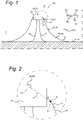
- Figure 1 schematically shows a floating object moored in a body of water illustrating an embodiment of the invention.
- a floating object 10 is moored by means of mooring lines 12 to anchoring bodies 14.
- Each anchoring body 14 is disposed on or in the sea bed 2 or lake bed 2.
- Each mooring line 12 is connected to the floating object 10 by means of a line connector 16, that comprises an articulation 18 to allow a line angle 22 between the mooring line and the vertical (i.e., a mooring line angle) to change depending on forces exerted on the floating object, such as low-tide, high-tide, currents and storm.
- a line connector 16 that comprises an articulation 18 to allow a line angle 22 between the mooring line and the vertical (i.e., a mooring line angle) to change depending on forces exerted on the floating object, such as low-tide, high-tide, currents and storm.
- risers 20 for transporting hydrocarbon liquid and/or gas may be running between well heads (not shown) on the sea bed 2 and the floating object 10.
- a system 50 is provided for determining the line angle 22 at the articulation 18 from the shape of the mooring line 12 between the floating object 10 and the anchoring body 14.
- an anchor line curve is referred to as an anchor line curve.
- the anchor line curve shape it is considered to measure a geographical location (hereafter: geolocation) of at least three points P1, P2, P3 on the anchor line curve or a geolocation of two points P1, P2 plus a locally measured line angle at a third point P3 on the anchor line curve.
- a curve fitting procedure is performed to obtain a set of parameters describing the anchor line curve as function of the geolocation. From the set of parameters, a derivative of the anchor line curve can be calculated at the geolocation of the articulation 18, which is a predetermined location on the mooring line. From the derivative of the anchor line curve at the geolocation of the articulation 18, the line angle 22 at the articulation with the vertical is then established.
- the locally measured line angle at the third point may be measured at a same location as the geolocation of the second point.
- the locations of the second and third points may coincide in that case.
- the system comprises at least first, second and third position sensors 52, 54, 56, that are to be installed on the mooring line to be measured.
- the system comprises a first device 58 for receiving from each position sensor 52, 54, 56 the respective position signal and a second device 60 for determining from each received position signal the location of the respective position sensor, the location of the point on the mooring line associated with the respective position sensor.
- each of the at least first, second and third position sensors 52, 54, 56 is a transponder that is configured to transmit a signal relating to the respective location thereof.
- the first device 58 is a transceiver that is configured to transmit signals to the position sensors to initiate the transmission of the location related signals from the transponders, and to receive the location related signals from the transponders.
- the location related signals can comprise data of either absolute locations or relative locations.
- the absolute locations can comprise geographical coordinates.
- the relative locations can comprise locations relative to the location of the first device 58.
- the first position sensor 52 is based on a first GPS sensor which is configured to produce first position sensor geolocation coordinates.
- the first GPS sensor is installed on the floating object 10. Using the first position sensor geolocation coordinates from the first GPS sensor 52 a location of the centre of the articulation 18 of the line connector 16 is determined as the geolocation of the first point P1. This will be explained in more detail with reference to Figure 2 , below.
- the signals of the first GPS sensor 52 are received by a suitable receiver (not shown) and transferred to the second device 60 as geolocation of the floating object 10.
- the first position sensor 52 is the first GPS sensor and the second and third position sensors 54, 56 are USBL (ultra-short baseline) transponders installed at a location of the second point and third point respectively.
- USBL ultra-short baseline
- a remotely operated underwater vehicle is used to install them on the mooring line.
- ROV remotely operated underwater vehicle
- the use of the ROV allows diver-less deployment of the underwater position sensors 54, 56.
- the location of the second point and third point are obtained by the USBL transceiver 58 from the readings of the USBL transponders 54, 56.
- the transceiver 58 and second device 60 are deployed on a support vessel 64, positioned at some distance from the floating object.
- the locations of the second point and third point can be referenced to absolute locations (geolocations) of the second point and third point P2, P3 through the GPS coordinates of the second GPS sensor 62 associated with the USBL transceiver 58.
- the second GPS sensor 62 is typically close to the USBL transceiver 58, on the support vessel 64. In this manner, the location of the USBL transceiver can be determined from a GPS location by the second GPS sensor associated with the USBL transceiver.
- the second device 60 is a computational device capable of executing a first computational procedure for determining parameter values of an equation describing an anchor line curve passing through the respective locations of said at least three points P1, P2, P3, obtained as described above, and may be based on any suitable numerical curve fitting method.
- the first computational procedure may comprise determining parameter values of an equation describing an anchor line curve passing through the respective locations of two points P1, P2, plus taking into account a locally measured line angle at a third point P3 (which third point may coincide with the second point).
- the second device 60 is capable of executing a second computational procedure for calculating at a predetermined position on the mooring line a line angle 22 with the vertical direction from a derivative of the equation of the anchor line curve based on the determined parameter values.
- the second device 60 can be a single computational device, or a number of computational devices arranged in a network, arranged for carrying out the computational procedures.
- the second device 60 is connected to the first device 58 for data-communication by a network (not shown), either wired or wireless, and may be located at a same location as the first device 58, but could be located at a different location.
- the line angle 22 at the articulation is determined from parameters describing the anchor line curve shape by using computation involving the derivative of the anchor line curve at the location of the articulation 18 of the line connector 16.
- Figure 2 schematically shows a part of Figure 1 in more detail.
- the centre of the articulation 18 of the line connector 16 is taken as the geolocation of the first point.
- the geolocation of the first point is then calculated from the geolocation of the first GPS sensor on the floating object 10 with a correction for the distance between a location L2 of the first GPS sensor on the floating object and a location L1 of the centre of the articulation 18.
- the correction can be determined from the actual layout of the floating object construction and a position of the centre of the articulation 18 of the line connector 16 at the floating object 10, corresponding to a distance vector denoted X (indicated by dashed line) between the centre of the articulation 18 and the actual position of the first GPS sensor 52 on the floating object 10, i.e., between location L2 and location L1.
- the correction is performed by the second device 60.
- Figure 3 shows a flow diagram of a method in accordance with an embodiment of the invention.
- a method for carrying out a procedure 300 to determine a line angle value 22 for the floating object 10 moored by the mooring line 12.
- the method comprises the installation of the first GPS sensor as the first sensor on the floating object and at least the second and third sensors on the mooring line. Also this step comprises the deployment of a measurement facility 64 comprising at least the first device 58 at some distance from the floating object and mooring line.
- the second device 60 may be located at the measurement facility 64 near the first device 58, but alternatively could be located at a different location.
- the method comprises the step of receiving by the first computational device 58, location related signals from the first position sensor and at least one of the second and third sensors.
- the first position sensor can be equipped with an attitude sensor to measure local attitude or local line angle related signal in combination with the position signal.
- location related signals are received from the second position sensor and local line angle related signals are received from the third sensor.
- the second device 60 is arranged to carry out a procedure 330 to determine the location of each of the first position sensor and at least the second and third sensor on the mooring line 12.
- the determined locations can be either relative locations, with relative positions with respect to the location of the measurement facility or absolute locations for example defined as geolocations.
- the second computation device 60 is arranged to carry out a procedure 340 to determine the location of the first point at the centre of the articulation 18 of the line connector 16 from the location of the first position sensor and the distance vector X.
- the second device 60 is arranged to carry out a procedure 350 to determine parameter values that describe the anchor line curve shape as a function of the location of the at least three points on the mooring line 12 (or the location of two points on the mooring line plus a local line angle at a point on the mooring line).
- the procedure 350 may use a curve fitting method to obtain the parameter values.
- the second device 60 is arranged to carry out a procedure 360 to determine a line angle value at the location of the centre of the articulation 18 of the line connector 16, by calculating the local derivative at the latter location.
- the line angle value can be determined repeatedly over time to obtain a time-average of the line angle value (and/or any one of the values of the curve fitting parameters, the locations of the at least three points and/or the locations of the at least three position sensors), by repeating the procedural steps 320 - 360, as described above.
- the method comprises in a step 380 that real-time values or time-averaged values of the line angle, and/or the curve fitting parameters, and/or the locations of the at least three points and/or the locations of the at least three position sensors are stored in a computer readable medium.
- Such a method may comprise storing a value of at least the calculated line angle with either the vertical or the horizontal direction in a computer readable medium, and/or storing a value of the measured positions for the at least three data points on the mooring line in a computer readable medium, and/or storing a value of measured position signals from the at least three position sensors in a computer readable medium, and/or storing a value of determined parameters of the equation describing the anchor line curve from the measured values associated with the location on the mooring line for said at least three data points.
- the stored data values can be used for example for on-line or off-line analysis, but also in relation to process monitoring or process control when a vessel (not shown) is moored at the floating object 10 for offloading liquid or gaseous hydrocarbons from the risers 20.
- the mooring buoy arrangement is used in a water depth of about 2000 m or less.
- Figure 4 schematically shows a floating object moored in a body of water illustrating an embodiment of the invention.
- a method for measuring the chain angle which comprises indirectly measuring a top angle of at least one mooring chain connected to a floating object 10 via a 3D bathymetry system 71 attached to an unmanned surface vehicle 70.
- the top angle is determined by fitting of the catenary line to bathymetry reflection points together with a 3D surface fit.
- the method comprises:
Landscapes
- Chemical & Material Sciences (AREA)
- Engineering & Computer Science (AREA)
- Combustion & Propulsion (AREA)
- Mechanical Engineering (AREA)
- Ocean & Marine Engineering (AREA)
- Physics & Mathematics (AREA)
- Analytical Chemistry (AREA)
- General Physics & Mathematics (AREA)
- Probability & Statistics with Applications (AREA)
- Position Fixing By Use Of Radio Waves (AREA)
- Testing Or Calibration Of Command Recording Devices (AREA)
- Length Measuring Devices With Unspecified Measuring Means (AREA)
- Testing Of Devices, Machine Parts, Or Other Structures Thereof (AREA)
Abstract
A method is disclosed for measuring a line angle of a mooring line connected to a floating object floating in a body of water, the mooring line being connected between the floating object and an anchoring body disposed in a bed of the body of water, in which the floating object is coupled to the mooring line by a line connector. The method includes; defining at least three data points each associated with a respective location on the mooring line; on the data points obtaining a value associated with the location on the mooring line; determining parameters of an equation describing an anchor line curve from the values associated with the location on the mooring line for the data points; calculating at a predetermined position on the mooring line a line angle of the mooring line from a derivative of the equation at the predetermined position based on the parameters.
Description
- The present invention relates to a method for measuring a line angle of a mooring line connected to a floating object. Also, the invention relates to a system for measuring a line angle of a mooring line connected to a floating object.
- There is a worldwide trend in the offshore industry to minimize diver intervention to reduce the associated risks of this kind of operation. At the same time, progress in automated control system have allowed the deployment of sophisticated vehicles in difficult environments.
- For a floating object such as a buoy that is moored at sea by mooring lines, a periodic inspection of the submerged part of the floating object is required to check the state of the mooring lines and to avoid unexpected failure thereof. Mooring lines comprise lines made from synthetic material such as nylon and polyester, and/or steel wire or combinations thereof. Also a mooring line may consist of a mooring chain consisting of steel links or may comprise at least a segment of such a mooring chain.
- One of the measures that need to be performed during the periodic inspection of the terminal is that of the line angles formed by the mooring lines with the vertical direction in close proximity of the buoy and of its mooring line connectors.
- In particular for catenary anchor leg based mooring, i.e., for CALM terminals, where the buoy responds to even moderate sea states with a considerable amplitude of motions and speeds, the approach to the buoy by a diver or a remotely operated device (ROV) can be difficult. For example, a wave height of about one metre, can cause motion excursions of several meters for the terminal.
- It is an object of the present invention to provide a method for measuring a line angle of the mooring line near the buoy, with adequate precision, but without divers or ROV and without directly approaching the buoy, thus avoiding a collision risk associated to large motions of the buoy.
- The object is achieved by a method in accordance with
claim 1 for measuring a line angle of at least one mooring line connected to a floating object, the floating object floating in a body of water, the mooring line being connected between the floating object and an anchoring body disposed in a bed of the body of water, in which the floating object is coupled to the mooring line by a line connector. - The method allows to measure the anchor line curve from either positions of at least three points or positions at a first and a second point plus a local line angle of the anchor line curve at a third point, and determine the line angle without the need to perform a measurement in the submerged zone adjacent to the buoy by a diver or ROV.
- The invention also relates to a system for measuring a line angle of a mooring line connected to a floating object, in accordance with claim 7. Moreover, the present invention relates to a floating object provided with a system for measuring a line angle of a mooring line connected to the floating object.
- Embodiments of the present invention will be described hereinafter, by way of example only, with reference to the accompanying drawings which are schematic in nature and therefore not necessarily drawn to scale. In the drawings, identical or similar elements are indicated by the same reference sign.
-
Figure 1 schematically shows a floating object moored in a body of water illustrating an embodiment of the invention; -
Figure 2 schematically shows a portion ofFigure 1 in more detail,
and -
Figure 3 shows a flow diagram of a method in accordance with an embodiment of the invention. -
Figure 1 schematically shows a floating object moored in a body of water illustrating an embodiment of the invention. - In a body of
water 1 such as a sea or lake, afloating object 10 is moored by means ofmooring lines 12 to anchoringbodies 14. Each anchoringbody 14 is disposed on or in the sea bed 2 or lake bed 2. - Each
mooring line 12 is connected to thefloating object 10 by means of aline connector 16, that comprises anarticulation 18 to allow aline angle 22 between the mooring line and the vertical (i.e., a mooring line angle) to change depending on forces exerted on the floating object, such as low-tide, high-tide, currents and storm. - Further, some
risers 20 for transporting hydrocarbon liquid and/or gas may be running between well heads (not shown) on the sea bed 2 and thefloating object 10. - To allow measurement of the line angle, a
system 50 is provided for determining theline angle 22 at thearticulation 18 from the shape of themooring line 12 between thefloating object 10 and theanchoring body 14. Here such a shape is referred to as an anchor line curve. - To determine the anchor line curve shape, it is considered to measure a geographical location (hereafter: geolocation) of at least three points P1, P2, P3 on the anchor line curve or a geolocation of two points P1, P2 plus a locally measured line angle at a third point P3 on the anchor line curve. Using the respective three geolocations (or the two geolocations plus a local line angle) of these at least one 3 points P1, P2, P3 a curve fitting procedure is performed to obtain a set of parameters describing the anchor line curve as function of the geolocation. From the set of parameters, a derivative of the anchor line curve can be calculated at the geolocation of the
articulation 18, which is a predetermined location on the mooring line. From the derivative of the anchor line curve at the geolocation of thearticulation 18, theline angle 22 at the articulation with the vertical is then established. - In case the geolocation of two points plus the locally measured line angle at the third point are measured, the locally measured line angle at the third point may be measured at a same location as the geolocation of the second point. The locations of the second and third points may coincide in that case.
- The system comprises at least first, second and third position sensors 52, 54, 56, that are to be installed on the mooring line to be measured.
- Further, the system comprises a
first device 58 for receiving from each position sensor 52, 54, 56 the respective position signal and asecond device 60 for determining from each received position signal the location of the respective position sensor, the location of the point on the mooring line associated with the respective position sensor. - In an embodiment, each of the at least first, second and third position sensors 52, 54, 56 is a transponder that is configured to transmit a signal relating to the respective location thereof. The
first device 58 is a transceiver that is configured to transmit signals to the position sensors to initiate the transmission of the location related signals from the transponders, and to receive the location related signals from the transponders. - Depending on the transponder or sensor type, the location related signals can comprise data of either absolute locations or relative locations. The absolute locations can comprise geographical coordinates. The relative locations can comprise locations relative to the location of the
first device 58. - In a further embodiment, the first position sensor 52 is based on a first GPS sensor which is configured to produce first position sensor geolocation coordinates. The first GPS sensor is installed on the
floating object 10. Using the first position sensor geolocation coordinates from the first GPS sensor 52 a location of the centre of thearticulation 18 of theline connector 16 is determined as the geolocation of the first point P1. This will be explained in more detail with reference toFigure 2 , below. The signals of the first GPS sensor 52 are received by a suitable receiver (not shown) and transferred to thesecond device 60 as geolocation of thefloating object 10. - In a preferred embodiment, the first position sensor 52 is the first GPS sensor and the second and third position sensors 54, 56 are USBL (ultra-short baseline) transponders installed at a location of the second point and third point respectively.
- According to a method of the invention, a remotely operated underwater vehicle (ROV) is used to install them on the mooring line. Advantageously, the use of the ROV allows diver-less deployment of the underwater position sensors 54, 56.
- The location of the second point and third point are obtained by the
USBL transceiver 58 from the readings of the USBL transponders 54, 56. Typically, thetransceiver 58 andsecond device 60 are deployed on asupport vessel 64, positioned at some distance from the floating object. - In case the
USBL transceiver 58 is associated with asecond GPS sensor 62, the locations of the second point and third point can be referenced to absolute locations (geolocations) of the second point and third point P2, P3 through the GPS coordinates of thesecond GPS sensor 62 associated with theUSBL transceiver 58. Thesecond GPS sensor 62 is typically close to theUSBL transceiver 58, on thesupport vessel 64. In this manner, the location of the USBL transceiver can be determined from a GPS location by the second GPS sensor associated with the USBL transceiver. - The
second device 60 is a computational device capable of executing a first computational procedure for determining parameter values of an equation describing an anchor line curve passing through the respective locations of said at least three points P1, P2, P3, obtained as described above, and may be based on any suitable numerical curve fitting method. - Alternatively, the first computational procedure may comprise determining parameter values of an equation describing an anchor line curve passing through the respective locations of two points P1, P2, plus taking into account a locally measured line angle at a third point P3 (which third point may coincide with the second point).
- Additionally, the
second device 60 is capable of executing a second computational procedure for calculating at a predetermined position on the mooring line aline angle 22 with the vertical direction from a derivative of the equation of the anchor line curve based on the determined parameter values. - An embodiment of the first and second computational procedures will be described in more detail with reference to
Figure 3 . - The skilled person will appreciate that the
second device 60 can be a single computational device, or a number of computational devices arranged in a network, arranged for carrying out the computational procedures. Thesecond device 60 is connected to thefirst device 58 for data-communication by a network (not shown), either wired or wireless, and may be located at a same location as thefirst device 58, but could be located at a different location. - According to the invention, the
line angle 22 at the articulation is determined from parameters describing the anchor line curve shape by using computation involving the derivative of the anchor line curve at the location of thearticulation 18 of theline connector 16. -
Figure 2 schematically shows a part ofFigure 1 in more detail. - In case the first position sensor 52 on the floating
object 10 is a first GPS sensor as described above, the centre of thearticulation 18 of theline connector 16 is taken as the geolocation of the first point. The geolocation of the first point is then calculated from the geolocation of the first GPS sensor on the floatingobject 10 with a correction for the distance between a location L2 of the first GPS sensor on the floating object and a location L1 of the centre of thearticulation 18. The correction can be determined from the actual layout of the floating object construction and a position of the centre of thearticulation 18 of theline connector 16 at the floatingobject 10, corresponding to a distance vector denoted X (indicated by dashed line) between the centre of thearticulation 18 and the actual position of the first GPS sensor 52 on the floatingobject 10, i.e., between location L2 and location L1. - In an embodiment, the correction is performed by the
second device 60. -
Figure 3 shows a flow diagram of a method in accordance with an embodiment of the invention. - According to an embodiment of the invention, a method is provided for carrying out a
procedure 300 to determine aline angle value 22 for the floatingobject 10 moored by themooring line 12. - In a
first step 310, the method comprises the installation of the first GPS sensor as the first sensor on the floating object and at least the second and third sensors on the mooring line. Also this step comprises the deployment of ameasurement facility 64 comprising at least thefirst device 58 at some distance from the floating object and mooring line. Thesecond device 60 may be located at themeasurement facility 64 near thefirst device 58, but alternatively could be located at a different location. - In a
subsequent step 320, the method comprises the step of receiving by the firstcomputational device 58, location related signals from the first position sensor and at least one of the second and third sensors. - Additionally, the first position sensor can be equipped with an attitude sensor to measure local attitude or local line angle related signal in combination with the position signal.
- In an alternative embodiment, location related signals are received from the second position sensor and local line angle related signals are received from the third sensor.
- In a next step, the
second device 60 is arranged to carry out aprocedure 330 to determine the location of each of the first position sensor and at least the second and third sensor on themooring line 12. The determined locations can be either relative locations, with relative positions with respect to the location of the measurement facility or absolute locations for example defined as geolocations. - In a subsequent step, the
second computation device 60 is arranged to carry out aprocedure 340 to determine the location of the first point at the centre of thearticulation 18 of theline connector 16 from the location of the first position sensor and the distance vector X. - In a next step, the
second device 60 is arranged to carry out aprocedure 350 to determine parameter values that describe the anchor line curve shape as a function of the location of the at least three points on the mooring line 12 (or the location of two points on the mooring line plus a local line angle at a point on the mooring line). Theprocedure 350 may use a curve fitting method to obtain the parameter values. - In a further step, the
second device 60 is arranged to carry out aprocedure 360 to determine a line angle value at the location of the centre of thearticulation 18 of theline connector 16, by calculating the local derivative at the latter location. - Optionally, the line angle value can be determined repeatedly over time to obtain a time-average of the line angle value (and/or any one of the values of the curve fitting parameters, the locations of the at least three points and/or the locations of the at least three position sensors), by repeating the procedural steps 320 - 360, as described above.
- In a further embodiment, the method comprises in a
step 380 that real-time values or time-averaged values of the line angle, and/or the curve fitting parameters, and/or the locations of the at least three points and/or the locations of the at least three position sensors are stored in a computer readable medium. - Such a method may comprise storing a value of at least the calculated line angle with either the vertical or the horizontal direction in a computer readable medium, and/or storing a value of the measured positions for the at least three data points on the mooring line in a computer readable medium, and/or storing a value of measured position signals from the at least three position sensors in a computer readable medium, and/or storing a value of determined parameters of the equation describing the anchor line curve from the measured values associated with the location on the mooring line for said at least three data points.
- The stored data values can be used for example for on-line or off-line analysis, but also in relation to process monitoring or process control when a vessel (not shown) is moored at the floating
object 10 for offloading liquid or gaseous hydrocarbons from therisers 20. - In an embodiment, the mooring buoy arrangement is used in a water depth of about 2000 m or less.
-
Figure 4 schematically shows a floating object moored in a body of water illustrating an embodiment of the invention. - In
Figure 4 entities with the same reference number as shown in Figure(s) 1-3 refer to corresponding entities. - According to an embodiment of the invention, a method is provided for measuring the chain angle which comprises indirectly measuring a top angle of at least one mooring chain connected to a floating
object 10 via a3D bathymetry system 71 attached to anunmanned surface vehicle 70. The top angle is determined by fitting of the catenary line to bathymetry reflection points together with a 3D surface fit. - The method comprises:
- i. navigating around the floating object with the unmanned surface vehicle 70 (a fully remotely operated survey vehicle) while acquiring a 3D point cloud representative of the subsea layout mapping underneath the floating terminal.
The3D bathymetry system 71, attached to theunmanned surface vehicle 70, emits acoustic waves towards the seabed and every time the acoustic waves come across a subsea structure, there is a reflection of the acoustic waves back to the bathymetry system. The amount of time it takes for the acoustic waves to bounce off structures on the seabed 2 and return to (a receiver of) the 3D bathymetry system is used to determine exact coordinates and depth of each reflection point, creating an accurate field layout mapping of all underwater structures underneath the floating object. - ii. post processing the respective 3D point cloud using advanced data analytics tools by interpolating a best-fitting 3D surface among the reflection points that represent the catenary line (for example by parametrizing a catenary line equation using nonlinear least-squares regression analysis) for one or more of the
mooring lines 12 while computing best confidence, prediction and calibration intervals using well-known statistical tools. - iii. calculating a top inclination (top angle) value of each measured mooring line with (predetermined) adequate precision and accuracy from a derivative of the equation of the anchor line curve at a predetermined position.
- The foregoing description details certain embodiments of the invention. It will be appreciated, however, that no matter how detailed the foregoing appears in text, the invention may be practiced in various ways.
- While the above detailed description has shown, described, and pointed out novel features of the invention as applied to various embodiments, it will be understood that various modifications in the form and details of the system or method illustrated may be made by those skilled in the art without departing from the spirit of the invention. The scope of the invention is indicated by the appended claims rather than by the foregoing description. All modifications that come within the meaning and range of equivalency of the claims are to be embraced within their scope.
Claims (8)
- A method for measuring a line angle of at least one mooring line connected to a floating object, the floating object floating in a body of water, the mooring line being connected between the floating object and an anchoring body disposed in a bed of the body of water, in which the floating object is coupled to the mooring line by a line connector;
the method comprising:▪ providing a 3D bathymetry system attached to an unmanned surface vehicle;▪ navigating around the floating object with the unmanned surface vehicle (70);▪ during said navigating acquiring a 3D point cloud representative of a subsea layout mapping underneath the floating object by the 3D bathymetry system;▪ creating a field layout mapping of underwater structures under the floating object by determining coordinates and depth of reflection points received by the 3D bathymetry system;▪ post processing the 3D point cloud among the reflection points by interpolating a best-fitting 3D surface to represent a catenary line equation parameters for said at least one mooring line;▪ calculating a top inclination (top angle) value of each represented catenary line parameters of said mooring line from a derivative of the catenary line equation at a predetermined position. - The method according to claim 1, wherein the catenary line equation parameters are determined by parametrizing a catenary line equation using nonlinear least-squares regression analysis.
- The method according to claim 2, said regression analysis further comprising computing best confidence, prediction and calibration intervals using statistical tools.
- The method according to claim 1, 2 or 3, wherein determining coordinates and depth of reflection points received by the 3D bathymetry system is based on an amount of time to bounce off bathymetry signals from the underwater structures.
- The method according to claim 1, wherein the predetermined position is a first location on the line connector, preferably a centre of an articulation of the line connector.
- The method according to any one of the preceding claims, wherein an average of the calculated line angle is determined as a function of time.
- A system for measuring a line angle of at least one mooring line connected to a floating object moored in a body of water by the mooring line, the mooring line being connected between the floating object and an anchoring body disposed on a bed of the body of water, in which the floating object is coupled to the mooring line by a line connector,wherein the system comprises an 3D bathymetry system and an unmanned surface vehicle, the 3D bathymetry system attached to the unmanned surface vehicle,the system being configured to carry out a method comprising:▪ navigating around the floating object with the unmanned surface vehicle (70);▪ during said navigating acquiring a 3D point cloud representative of a subsea layout mapping underneath the floating object by the 3D bathymetry system;▪ creating a field layout mapping of underwater structures under the floating object by determining coordinates and depth of reflection points received by the 3D bathymetry system based on an amount of time to bounce off the underwater structures;▪ post processing the 3D point cloud among the reflection points by interpolating a best-fitting 3D surface to represent a catenary line equation parameters for said at least one mooring line;▪ calculating a top inclination (top angle) value of each represented catenary line parameters of said mooring line from a derivative of the catenary line equation at a predetermined position.
- A floating object moored in a body of water by at least one mooring line, the mooring line being connected between the floating object and an anchoring body disposed in a bed of the body of water, in which the floating object is coupled to the mooring line by a line connector, provided with a system for measuring a line angle of the at least one mooring line in accordance with claim 7.
Applications Claiming Priority (3)
| Application Number | Priority Date | Filing Date | Title |
|---|---|---|---|
| EP19167343 | 2019-04-04 | ||
| EP20701653.6A EP3947134B1 (en) | 2019-04-04 | 2020-01-30 | A method for inspection of catenary anchor lines connected to a floating object |
| PCT/EP2020/052338 WO2020200541A1 (en) | 2019-04-04 | 2020-01-30 | A method for inspection of catenary anchor lines connected to a floating object |
Related Parent Applications (2)
| Application Number | Title | Priority Date | Filing Date |
|---|---|---|---|
| EP20701653.6A Division-Into EP3947134B1 (en) | 2019-04-04 | 2020-01-30 | A method for inspection of catenary anchor lines connected to a floating object |
| EP20701653.6A Division EP3947134B1 (en) | 2019-04-04 | 2020-01-30 | A method for inspection of catenary anchor lines connected to a floating object |
Publications (1)
| Publication Number | Publication Date |
|---|---|
| EP4056458A1 true EP4056458A1 (en) | 2022-09-14 |
Family
ID=66092208
Family Applications (2)
| Application Number | Title | Priority Date | Filing Date |
|---|---|---|---|
| EP22171188.0A Pending EP4056458A1 (en) | 2019-04-04 | 2020-01-30 | A method for inspection of catenary anchor lines connected to a floating object |
| EP20701653.6A Active EP3947134B1 (en) | 2019-04-04 | 2020-01-30 | A method for inspection of catenary anchor lines connected to a floating object |
Family Applications After (1)
| Application Number | Title | Priority Date | Filing Date |
|---|---|---|---|
| EP20701653.6A Active EP3947134B1 (en) | 2019-04-04 | 2020-01-30 | A method for inspection of catenary anchor lines connected to a floating object |
Country Status (9)
| Country | Link |
|---|---|
| US (1) | US12116087B2 (en) |
| EP (2) | EP4056458A1 (en) |
| JP (1) | JP7472164B2 (en) |
| KR (1) | KR102847652B1 (en) |
| CN (1) | CN113692378B (en) |
| CA (1) | CA3135229A1 (en) |
| MX (1) | MX2021012093A (en) |
| MY (1) | MY209962A (en) |
| WO (1) | WO2020200541A1 (en) |
Families Citing this family (4)
| Publication number | Priority date | Publication date | Assignee | Title |
|---|---|---|---|---|
| US20220204061A1 (en) * | 2012-08-10 | 2022-06-30 | Transportation Ip Holdings, Llc | Examining system and method |
| JP7472164B2 (en) * | 2019-04-04 | 2024-04-22 | シングル・ブイ・ムーリングス・インコーポレイテッド | Method for inspecting a suspension anchor line connected to a floating object |
| CN115442761A (en) * | 2022-08-08 | 2022-12-06 | 中钢集团郑州金属制品研究院股份有限公司 | Friction coefficient detection system and detection method based on wireless transmission |
| KR20240096215A (en) * | 2022-12-19 | 2024-06-26 | 주식회사 포스코 | Mooring apparatus, offshore wind power generator and control method thereof |
Citations (5)
| Publication number | Priority date | Publication date | Assignee | Title |
|---|---|---|---|---|
| US3810081A (en) * | 1972-11-15 | 1974-05-07 | Global Marine Inc | Submerged chain angle measurement |
| US20060207488A1 (en) * | 2005-03-18 | 2006-09-21 | Shell Oil Company | Method and apparatus for handling mooring lines |
| WO2007079556A1 (en) * | 2006-01-09 | 2007-07-19 | Anselmo Carvalho Pontes | Method, device and system to monitor underwater lines |
| US20130239649A1 (en) * | 2010-09-15 | 2013-09-19 | Catenary Testing Limited | Method of determining the tension in a mooring line |
| WO2015011871A1 (en) * | 2013-07-22 | 2015-01-29 | ヤマハ発動機株式会社 | Route determination device and autonomous mobile body system provided with same |
Family Cites Families (18)
| Publication number | Priority date | Publication date | Assignee | Title |
|---|---|---|---|---|
| JPS5932584A (en) * | 1982-08-17 | 1984-02-22 | Hitachi Zosen Corp | Floating mooring device |
| GB8300176D0 (en) * | 1983-01-05 | 1983-02-09 | Shell Int Research | Surveying positions of mooring lines |
| US4912464A (en) * | 1989-02-17 | 1990-03-27 | Bachman Donald H | Anchor alarm for boats and the like |
| JP3202444B2 (en) * | 1993-09-27 | 2001-08-27 | 三菱重工業株式会社 | Evacuation device for deep sea suspension pipe |
| GB9508476D0 (en) * | 1995-04-26 | 1995-06-14 | Brupat Ltd | Mooring bed assessment apparatus and method |
| US20090287414A1 (en) * | 2007-05-14 | 2009-11-19 | Zupt, Llc | System and process for the precise positioning of subsea units |
| NL2002086C (en) * | 2008-10-10 | 2010-04-13 | Stevlos Bv | ANCHOR WITH MEASUREMENT COUPLING. |
| JP2012236445A (en) * | 2011-05-10 | 2012-12-06 | Mitsui Eng & Shipbuild Co Ltd | Mooring buoy system, mooring buoy, and tension calculation method for mooring rope |
| CN103010415B (en) * | 2011-09-22 | 2015-08-19 | 江门强光海洋工程股份有限公司 | Support the prestressed concrete floating platform of offshore wind turbine and ocean power generator |
| CN102385051A (en) * | 2011-11-08 | 2012-03-21 | 中国海洋石油总公司 | Device and method for monitoring mooring system based on short base line hydro-acoustic positioning |
| KR101379510B1 (en) * | 2012-07-27 | 2014-03-27 | 삼성중공업 주식회사 | Monitoring system for equipment of underwater |
| CN103295078B (en) * | 2013-05-21 | 2016-03-16 | 中国海洋石油总公司 | The structural design optimization method of deep water catenary mooring line |
| KR101599452B1 (en) * | 2014-02-18 | 2016-03-03 | 삼성중공업 주식회사 | Apparatus for preventing chain from damage for turret |
| US9671231B2 (en) * | 2015-07-20 | 2017-06-06 | Technip France | Monitoring system and method for vessel mooring |
| US20190233070A1 (en) | 2016-10-24 | 2019-08-01 | Seabed Geosolutions B.V. | Catenary modeling for a plurality of deployment lines for an offshore seismic system |
| US10370962B2 (en) * | 2016-12-08 | 2019-08-06 | Exxonmobile Research And Engineering Company | Systems and methods for real-time monitoring of a line |
| US10618788B2 (en) * | 2017-05-23 | 2020-04-14 | Goodrich Corporation | Hoist cable load sensor |
| JP7472164B2 (en) * | 2019-04-04 | 2024-04-22 | シングル・ブイ・ムーリングス・インコーポレイテッド | Method for inspecting a suspension anchor line connected to a floating object |
-
2020
- 2020-01-30 JP JP2021559137A patent/JP7472164B2/en active Active
- 2020-01-30 MX MX2021012093A patent/MX2021012093A/en unknown
- 2020-01-30 MY MYPI2021005627A patent/MY209962A/en unknown
- 2020-01-30 US US17/600,879 patent/US12116087B2/en active Active
- 2020-01-30 KR KR1020217035604A patent/KR102847652B1/en active Active
- 2020-01-30 CA CA3135229A patent/CA3135229A1/en active Pending
- 2020-01-30 CN CN202080027326.7A patent/CN113692378B/en active Active
- 2020-01-30 WO PCT/EP2020/052338 patent/WO2020200541A1/en not_active Ceased
- 2020-01-30 EP EP22171188.0A patent/EP4056458A1/en active Pending
- 2020-01-30 EP EP20701653.6A patent/EP3947134B1/en active Active
Patent Citations (5)
| Publication number | Priority date | Publication date | Assignee | Title |
|---|---|---|---|---|
| US3810081A (en) * | 1972-11-15 | 1974-05-07 | Global Marine Inc | Submerged chain angle measurement |
| US20060207488A1 (en) * | 2005-03-18 | 2006-09-21 | Shell Oil Company | Method and apparatus for handling mooring lines |
| WO2007079556A1 (en) * | 2006-01-09 | 2007-07-19 | Anselmo Carvalho Pontes | Method, device and system to monitor underwater lines |
| US20130239649A1 (en) * | 2010-09-15 | 2013-09-19 | Catenary Testing Limited | Method of determining the tension in a mooring line |
| WO2015011871A1 (en) * | 2013-07-22 | 2015-01-29 | ヤマハ発動機株式会社 | Route determination device and autonomous mobile body system provided with same |
Also Published As
| Publication number | Publication date |
|---|---|
| JP2022526981A (en) | 2022-05-27 |
| WO2020200541A1 (en) | 2020-10-08 |
| CA3135229A1 (en) | 2020-10-08 |
| KR102847652B1 (en) | 2025-08-19 |
| US20220185431A1 (en) | 2022-06-16 |
| EP3947134B1 (en) | 2024-12-18 |
| EP3947134A1 (en) | 2022-02-09 |
| KR20210150451A (en) | 2021-12-10 |
| MY209962A (en) | 2025-08-15 |
| MX2021012093A (en) | 2021-11-03 |
| US12116087B2 (en) | 2024-10-15 |
| CN113692378A (en) | 2021-11-23 |
| CN113692378B (en) | 2024-07-19 |
| JP7472164B2 (en) | 2024-04-22 |
Similar Documents
| Publication | Publication Date | Title |
|---|---|---|
| EP3947134B1 (en) | A method for inspection of catenary anchor lines connected to a floating object | |
| AU2018248022B2 (en) | Automated draft survey | |
| AU2000234653B2 (en) | Apparatus for deploying a load to an underwater target position with enhanced accuracy and a method to control such apparatus | |
| EP2616786B1 (en) | Method of determining the tension in a mooring line | |
| KR20150117468A (en) | Ocean observing bouy system and method using anchor | |
| CA2640301C (en) | Method for simulating the positioning of at least one streamer comprising a step for predicting the current on at least two distinct points of the streamer | |
| JP6241995B2 (en) | Diver information acquisition method and diver information acquisition system | |
| JP5777049B2 (en) | Wave measuring method and wave measuring system using ultrasonic waves | |
| KR101408211B1 (en) | Apparatus for measuring position of rov | |
| CN106645622A (en) | Operation method of water quality detection robot | |
| RU2282217C1 (en) | Method of determining comprehensive data on ocean condition | |
| US4610007A (en) | Method and apparatus for surveying positions of mooring lines | |
| CN114966711A (en) | Manned submersible vehicle-oriented seawater depth determination method and system | |
| Chang et al. | Preliminary test of Tide-independent Bathymetric measurement Based on GPS | |
| RU2559311C1 (en) | Assessment method of state of ice field | |
| JP4830269B2 (en) | Mooring sensor positioning method and apparatus | |
| Castro et al. | Diverless Underwater Inspection by Marine Drone: Unmanned Vehicle to Optimize Structural Integrity and Life Extension Programs | |
| JP4485895B2 (en) | A device for measuring the position of a device in water, including an acoustic array with a sound velocity meter | |
| JP2009047699A (en) | Navigation processor, processing configuration having the navigation processor, measuring system having the navigation processor, and method for measuring position and attitude of underwater system | |
| Reichert et al. | X-Band radar derived sea surface elevation maps as input to ship motion forecasting | |
| JP2005351685A (en) | Position measurement method for object in sea and on sea surface | |
| Dannenberg et al. | Wave profiles derived from nautical X-band radar as data source for ship motion prediction | |
| Caiti et al. | Underwater archaeology: available techniques and open problems in fully automated search and inspection | |
| US20240017420A1 (en) | Non-destructive device and method for surveying, inspection, and cleaning marine growth around offshore structure | |
| CN121899748A (en) | A method for positioning ships during offshore construction |
Legal Events
| Date | Code | Title | Description |
|---|---|---|---|
| PUAI | Public reference made under article 153(3) epc to a published international application that has entered the european phase |
Free format text: ORIGINAL CODE: 0009012 |
|
| STAA | Information on the status of an ep patent application or granted ep patent |
Free format text: STATUS: REQUEST FOR EXAMINATION WAS MADE |
|
| 17P | Request for examination filed |
Effective date: 20220502 |
|
| AC | Divisional application: reference to earlier application |
Ref document number: 3947134 Country of ref document: EP Kind code of ref document: P |
|
| AK | Designated contracting states |
Kind code of ref document: A1 Designated state(s): AL AT BE BG CH CY CZ DE DK EE ES FI FR GB GR HR HU IE IS IT LI LT LU LV MC MK MT NL NO PL PT RO RS SE SI SK SM TR |