EP4056447B1 - Gauge-variable wheelset and rail vehicle - Google Patents
Gauge-variable wheelset and rail vehicle Download PDFInfo
- Publication number
- EP4056447B1 EP4056447B1 EP21851372.9A EP21851372A EP4056447B1 EP 4056447 B1 EP4056447 B1 EP 4056447B1 EP 21851372 A EP21851372 A EP 21851372A EP 4056447 B1 EP4056447 B1 EP 4056447B1
- Authority
- EP
- European Patent Office
- Prior art keywords
- axle
- locking
- gauge
- positioning
- outer sleeve
- Prior art date
- Legal status (The legal status is an assumption and is not a legal conclusion. Google has not performed a legal analysis and makes no representation as to the accuracy of the status listed.)
- Active
Links
Images


Classifications
-
- B—PERFORMING OPERATIONS; TRANSPORTING
- B61—RAILWAYS
- B61F—RAIL VEHICLE SUSPENSIONS, e.g. UNDERFRAMES, BOGIES OR ARRANGEMENTS OF WHEEL AXLES; RAIL VEHICLES FOR USE ON TRACKS OF DIFFERENT WIDTH; PREVENTING DERAILING OF RAIL VEHICLES; WHEEL GUARDS, OBSTRUCTION REMOVERS OR THE LIKE FOR RAIL VEHICLES
- B61F7/00—Rail vehicles equipped for use on tracks of different width
-
- B—PERFORMING OPERATIONS; TRANSPORTING
- B60—VEHICLES IN GENERAL
- B60B—VEHICLE WHEELS; CASTORS; AXLES FOR WHEELS OR CASTORS; INCREASING WHEEL ADHESION
- B60B35/00—Axle units; Parts thereof ; Arrangements for lubrication of axles
-
- B—PERFORMING OPERATIONS; TRANSPORTING
- B60—VEHICLES IN GENERAL
- B60B—VEHICLE WHEELS; CASTORS; AXLES FOR WHEELS OR CASTORS; INCREASING WHEEL ADHESION
- B60B35/00—Axle units; Parts thereof ; Arrangements for lubrication of axles
- B60B35/02—Dead axles, i.e. not transmitting torque
- B60B35/10—Dead axles, i.e. not transmitting torque adjustable for varying track
-
- B—PERFORMING OPERATIONS; TRANSPORTING
- B60—VEHICLES IN GENERAL
- B60B—VEHICLE WHEELS; CASTORS; AXLES FOR WHEELS OR CASTORS; INCREASING WHEEL ADHESION
- B60B17/00—Wheels characterised by rail-engaging elements
-
- B—PERFORMING OPERATIONS; TRANSPORTING
- B60—VEHICLES IN GENERAL
- B60B—VEHICLE WHEELS; CASTORS; AXLES FOR WHEELS OR CASTORS; INCREASING WHEEL ADHESION
- B60B35/00—Axle units; Parts thereof ; Arrangements for lubrication of axles
- B60B35/02—Dead axles, i.e. not transmitting torque
- B60B35/04—Dead axles, i.e. not transmitting torque straight
-
- B—PERFORMING OPERATIONS; TRANSPORTING
- B60—VEHICLES IN GENERAL
- B60Y—INDEXING SCHEME RELATING TO ASPECTS CROSS-CUTTING VEHICLE TECHNOLOGY
- B60Y2200/00—Type of vehicle
- B60Y2200/30—Railway vehicles
-
- Y—GENERAL TAGGING OF NEW TECHNOLOGICAL DEVELOPMENTS; GENERAL TAGGING OF CROSS-SECTIONAL TECHNOLOGIES SPANNING OVER SEVERAL SECTIONS OF THE IPC; TECHNICAL SUBJECTS COVERED BY FORMER USPC CROSS-REFERENCE ART COLLECTIONS [XRACs] AND DIGESTS
- Y02—TECHNOLOGIES OR APPLICATIONS FOR MITIGATION OR ADAPTATION AGAINST CLIMATE CHANGE
- Y02T—CLIMATE CHANGE MITIGATION TECHNOLOGIES RELATED TO TRANSPORTATION
- Y02T10/00—Road transport of goods or passengers
- Y02T10/80—Technologies aiming to reduce greenhouse gasses emissions common to all road transportation technologies
- Y02T10/86—Optimisation of rolling resistance, e.g. weight reduction
Definitions
- the present application relates to the technical field of railway vehicle gauge changing, and in particular, to a gauge-changing wheelset and a railway vehicle.
- Gauge-changing wheelsets are known from DE 737 575 C , CN 109 572 740 A and CH 502 913 A , for instance.
- the present application further provides a railway vehicle.
- a gauge-changing wheelset including an axle, a pair of wheels, a pair of axle sleeves, an outer sleeve and a linkage mechanism;
- an outer circumference of the axle close to a middle portion thereof is provided with a section of outer spline extending in an axial direction of the axle, and the outer spline of the axle is provided with an oblong hole radially extending through the outer spline and having a longitudinal direction coinciding with the axial direction of the axle.
- the linkage mechanism includes a locking slip ring, a thrust pin and a locking elastic piece; and the locking slip ring is slidably sleeved at the outer spline of the axle, and the locking slip ring is provided therein with an inner spline matched with the outer spline of the axle, and provided externally with an outer spline matched with the inner spline of the outer sleeve.
- An inner wall of the locking slip ring is radially provided with a pair of open grooves having openings communicated with an end of the locking slip ring.
- the thrust pin passes through the oblong hole, and both ends of the thrust pin extend out of the oblong hole and both ends of the thrust pin exposed outside the oblong hole are embedded inside the pair of the open grooves by the openings of the open grooves.
- the locking elastic piece is sleeved on the axle, and has an end abutted against an outer wall of the first raceway, and another end abutted against an end of the locking slip ring away from the open groove.
- the outer spline outside the locking slip ring is at least partially located in the inner spline of a corresponding side of the outer sleeve to lock the rotation of the outer sleeve.
- the gauge-changing wheelset further includes a thrust rod penetrating through a central through hole provided along the axial direction of the axle, an end of the thrust rod penetrates through the central through hole of the axle and abuts against a side of the thrust pin at which the open groove is located, and another end of the thrust rod extends to an end portion of the axle.
- the thrust rod pushes the locking slip ring to compress the locking elastic piece and disengage from the inner spline of the outer sleeve by applying a thrust to the thrust rod, so as to unlock the rotation of the outer sleeve relative to the axle.
- the first non-self-locking thread has a length greater than the length of the second non-self-locking thread and equal to half of the gauge to be changed;
- the gauge-changing wheelset further includes a thrust converting mechanism, and axle-box bodies mounted at both ends of the axle and outside the wheels;
- the mounting base includes a base body and an extending base extending to a side along the base body, and the base body and the extending base are connected to each other by a frustum-shaped transition connecting base having a large end connected with the base body and a small end connected with the extending base, and a periphery of the base body is provided with connecting holes and the horizontal through hole penetrate through the extending base, the transition connecting base and the base body.
- the lower side of the extending base is provided with a notch penetrating through an end thereof;
- the outer end of the extending base is provided with a jacking gland
- a jacking shaft support ring is fixed at the end of the axle and is disposed coaxially with the central through hole.
- the jacking shaft support ring partially extends inside the central through hole and has an inner diameter matched with an outer diameter of the jacking shaft; and the jacking shaft enters the central through hole through the jacking shaft support ring and is configured to push the thrust rod.
- a railway vehicle including a vehicle body and a bogie disposed under the vehicle body, and each of the bogies is provided with a pair of the gauge-changing wheelsets.
- the linkage mechanism is mounted between the axle and the outer sleeve for locking or unlocking the rotation of the outer sleeve relative to the axle; and when the rotation of the outer sleeve relative to the axle is unlocked by the linkage mechanism and the wheels are in an unloaded state, the pair of wheels are pushed to rotate synchronously to move closer to each other or away from each other so as to change the gauge, resulting in a simple gauge-changing operation and high reliability in changing gauge.
- the railway vehicle according to an embodiment of the present application has all the advantages of the gauge-changing wheelset by being equipped with the above-mentioned gauge-changeable wheelset, which will not be repeated here.
- axle 11. outer spline of axle; 12. oblong hole; 13. first raceway; 14. second non-self-locking thread; 15. central through hole; 20. axle sleeve; 21. first non-self-locking thread; 22. outer spline of axle sleeve; 23. sliding bearing mounting groove; 24. wheel mounting base; 25. sliding bearing gland mounting groove; 30. wheel; 40. outer sleeve; 41. second raceway; 42. inner spline; 50. axle-box body; 60. locking slip ring; 70. locking spring; 80. thrust pin; 90. thrust rod; 100. thrust converting mechanism; 101. mounting base; 101-1. base body; 101-2. transition connecting base; 101-3. extending base; 102.
- jacking shaft 102-1. jacking portion; 103. positioning pin; 104. preloaded spring; 105. friction block; 106. jacking gland; 107. jacking shaft support ring; 110. sliding bearing; 120. gear box; 130. brake disc; 140. gear box mounting base; 150. brake disc mounting interface.
- orientation or positional relationships indicated by terms such as “center”, “longitudinal”, “lateral”, “upper”, “lower”, “front”, “rear”, “left”, “right”, “vertical”, “horizontal”, “top”, “bottom”, “inside”, “outside”, etc. are based on the orientation or positional relationship shown in the drawings, and are merely for the convenience of describing the embodiments of the present application and simplifying the description, rather than indicating or implying that the device or component stated must have a particular orientation, is constructed and operated in a particular orientation, and thus is not to be construed as limiting the embodiments of the present application.
- the terms “first”, “second”, “third”, and the like are used for descriptive purposes only and are not to be construed as indicating or implying relative importance.
- connection with shall be understood broadly, for example, it may be either fixedly connected or detachably connected, or can be integrated; it may be mechanically connected, or electrically connected; it may be directly connected, or indirectly connected through an intermediate medium.
- connection shall be understood broadly, for example, it may be either fixedly connected or detachably connected, or can be integrated; it may be mechanically connected, or electrically connected; it may be directly connected, or indirectly connected through an intermediate medium.
- the first feature being located “on” or “under” the second feature means that the first feature is in direct contact with the second feature or the first feature is in contact with the second feature by an intervening media.
- the first feature being located “on”, “above” and “on top of” the second feature may mean that the first feature is directly on or above the second feature, or it simply means that the level of the first feature is higher than the second feature.
- the first feature being located “under”, “below” and “on bottom of” the second feature may mean that the first feature is directly under or below the second feature, or it simply means that the level of the first feature is lower than the second feature.
- an embodiment of the present application provides a gauge-changing wheel set.
- a gauge-change wheelset includes an axle sleeve 20, an outer sleeve 40, an axle 10, a pair of wheels 30 and a linkage mechanism.
- each axle sleeve An outer circumference of a first end of each axle sleeve is provided with a wheel mounting base 24 having a width consistent with the width of the hub of each wheel 30, the wheel 30 is fastened on the wheel mounting base 24, and may be in interference fit with the wheel mounting base 24 so as to ensure the reliability of the connection between the two.
- An inner circumference of the second end of each axle sleeve 20 is provided with a section of a first non-self-locking thread 21.
- the first non-self-locking threads 21 of the pair of axle sleeves 20 have opposite directions of rotation, and the pair of wheels 30 are fastened on the wheel mounting bases 24 of the pair of axle sleeves 20.
- the axle 10 is provided with two sections of second non-self-locking threads 14 that form a non-self-locking thread pair with the first non-self-locking thread 21 at intervals, that is, the pair of second non-self-locking threads 14 also have opposite directions of rotation.
- the wheels 30 are mounted on the axle 10 through the axle sleeves 20, and each first non-self-locking thread 21 is connected with each second non-self-locking thread 14.
- the pair of wheels 30 When the pair of wheels 30 is pushed inward or outward at the same time after the wheels 30 are unloaded, due to the non-self-locking thread pair having opposite direction of rotation, the pair of wheels 30 may move closer to each other or away from each other when they rotate in the same direction until they move to a set gauge-changing position so as to change the gauge.
- the wheels 30 By arranging the axle sleeve 20, the wheels 30 can easily slide along the axle 10 to change the gauge, and the connection structure of the axle 10 and the wheel 30 is simple, and the gauge-changing reliability is high.
- the first non-self-locking thread 21 has a length greater than the length of the second non-self-locking thread 14, and the length difference is equal to half of the gauge to be changed, so that both wheels 30 can move half of the gauge to be changed relative to the axle 10 during the rotation by following respective axle sleeves 20, so that a sum of the distances along which both wheels 30 move is equal to the distance of the desired gauge to be changed.
- a sliding bearing mounting groove 23 extending from a first end to a second end of the axle sleeve 20 at an inner circumference of the axle sleeve 20 is used for mounting a sliding bearing 110.
- the sliding bearing mounting groove 23 extends to a position close to the first non-self-locking thread 21, and has a length equal to a length of the sliding bearing 110.
- the inner circumference of the axle sleeve 20 is provided with a sealing ring mounting groove at the position between the sliding bearing mounting groove 23 and the first non-self-locking thread 21, and the sealing ring mounting groove is used for mounting the sealing ring so as to seal the end of the sliding bearing 110.
- the first end of the axle sleeve 20 is provided with a sliding bearing gland mounting groove 25 used to mount the sliding bearing gland.
- a plurality of threaded holes are disposed at the circumferential bottom surface of the sliding bearing gland mounting groove 25 at intervals, so that the sliding bearing gland is fixed in the sliding bearing gland mounting groove 25 by a fastener and the sliding bearing 110 is fixed by the sliding bearing gland.
- an inner circumference of the sliding bearing gland is provided with a sealing ring mounting groove for mounting the sealing ring, thereby forming a sealing structure at both ends of the sliding bearing 110 to prevent grease from entering the joint surface of the sliding bearing 110 and the axle 10.
- the outside of the axle sleeve 20 has a three-stage stepped shape having a descending diameter from the first end to the second end and the wheel mounting base 24 has the largest diameter and the highest strength, and adjacent steps are connected by arc surface transition so as to avoid stress concentration at the connection between the steps.
- an outer circumference of the axle 10 close to a middle portion thereof is provided with a section of outer spline extending in the axial direction of the axle 10, and both axial sides of the outer spline 11 of the axle at the outer circumference thereof are provided with a pair of second non-self-locking threads 14 having opposite direction of rotation, that is, the axle 10 is further provided with two sections of second non-self-locking thread 14 having opposite direction of rotation disposed at both axial sides of the outer spline 11.
- the outer spline 11 of the axle 10 is provided with an oblong hole 12 radially extending through the outer spline. That is, the oblong hole 12 is disposed to coincide with the outer spline, and has a longitudinal direction along the axial direction of the axle, that is, the oblong hole 12 has a longitudinal direction consistent with the extending direction of the outer spline 11 of the axle.
- a part of the axle 20 between one of the second non-self-locking threads 14 and the outer spline 11 of the axle is provided with at least one first raceway 13 circumferentially disposed around the axle 10, and the first raceway 13 is disposed close to the outer spline 11 of the axle.
- the first raceway 13 has a cross section of concave semicircle.
- the outer sleeve 40 is sleeved outside the axle 10, an inner circumference of the outer sleeve 40 is provided with a second raceway 41 corresponding to the first raceway 13, and the second raceway 41 has the same size and shape as those of the first raceway 13. That is, the second raceway 41 also has a cross section of concave semicircle.
- the second raceway 41 is provided with a rolling element mounting hole and is snap-fitted with the first raceway 13 to form a circular rolling space in which a rolling element is mounted through the rolling element mounting hole.
- the rolling element which may be a rolling ball, has an outer diameter matched with an inner diameter of the rolling space.
- the rolling space is filled with the rolling elements.
- a sealing plug is provided at the rolling element mounting hole.
- the outer circumference of the second end of the axle sleeve 20 is provided with a section of outer splines extending along its axial direction. After being mounted, the second end of the axle sleeve 20 is located inside the wheel 30 and faces the outer sleeve 40; inner splines 42 matched with the outer splines on the axle sleeve 20 are respectively disposed on both axial sides of the second raceway 41 45- inside the inner circumference of the outer sleeve and located at a predetermined interval from the second raceway 41.
- the axle sleeve 20 and the outer sleeve 40 are connected through the inner splines 42 of the outer sleeve 40 and the outer splines 22 of the axle sleeve 20 such that the axle sleeve 20 can rotate together with the outer sleeve 40, or the axle sleeve 20 can move axially relative to the outer sleeve 40.
- the axle sleeve 20 by arranging the axle sleeve 20, the torque transmission between the wheel 30 and the outer sleeve 40 and the lateral slip between the wheel 30 and the axle 10 are realized.
- the axle sleeve 20 has a simple and reliable structure, and can be used for the conversion among various gauges.
- predetermined interval can be set according to specific needs, and the predetermined interval between the inner splines 42 on both axial sides of the second raceway 41 and the second raceway 41 can be different.
- the linkage mechanism is mounted between the axle 10 and the outer sleeve 40 for locking or unlocking the rotation of the outer sleeve 40 relative to the axle 10; and when the rotation of the outer sleeve 40 relative to the axle 10 is unlocked by the linkage mechanism and the wheels 30 are in an unloaded state, the pair of wheels 30 are pushed to rotate synchronously such that they move closer to each other or away from each other until the gauge to be changed is reached and thus the gauge is changed.
- the gauge-changing wheelset of the present embodiment further includes a thrust rod 90.
- a central through hole through which the thrust rod 90 penetrates is provided along the axial direction of the axle 10.
- the thrust rod 90 has an end connected with the linkage mechanism and the other end extending to an outer end of the axle.
- the linkage mechanism includes a locking slip ring 60, a thrust pin 80 and a locking elastic piece.
- the locking slip ring 60 is slidably sleeved at the outer spline 11 of the axle, and the locking slip ring is provided therein with an inner spline 42 matched with the outer spline 11 of the axle, and provided externally with an outer spline matched with the inner spline 42 of the outer sleeve 40.
- An inner wall of the locking slip ring 60 is radially provided with a pair of open grooves having openings communicated with an end of the locking slip ring 60.
- the thrust pin 80 passes through the oblong hole 12 and both ends of the thrust pin 80 extend out of the oblong hole 12, and both ends of the thrust pin 80 exposed outside the oblong hole 12 are embedded inside the pair of the open grooves by the openings of the open grooves.
- the thrust pin 80 has a length consistent with a distance between the top walls of the pair of open grooves, and both ends of the thrust pin 80 abut against the top walls of the open groove.
- the thrust pin 80 has a width consistent with widths of the open grooves such that the thrust pin 80 and the locking slip ring 60 have reliable connection.
- the thrust pin 80 has a width smaller than the length of the oblong hole 12, and a thickness less than or equal to the width of the oblong hole 12.
- the width of the locking slip ring 60 should not be too wide to ensure that the locking slip ring 60 can have an amount of movement in the space between the second raceway 41 of the outer sleeve 40 and the inner spline 42 of the outer sleeve 40.
- the oblong hole 12 should have a length lightly smaller than the length of the outer spline 11 of the axle, so that the locking slip ring 60 always moves on the outer spline 11 of the axle.
- the locking elastic piece for example, an elastic spring 70
- the locking elastic piece is sleeved on the axle, and has an end abutted against an outer wall, i.e., a stop end surface of the first raceway 13, and the other end abutted against an end of the locking slip ring 60 away from the open groove.
- the outer spline 42 outside the locking slip ring 60 is at least partially located in the inner spline 42 of a corresponding side of the outer sleeve 40 to lock the rotation of the outer sleeve 40 for fixing the outer sleeve relative to the axle 10.
- the wheels and the axle sleeve 20 as well as the outer sleeve 40 and the axle 10 are integrated and have no rotation relative to each other, and the wheels 30 are in a locked state.
- an end of the thrust rod 90 penetrates into the central through hole 15 of the axle 10 and abuts against a side of the thrust pin 80 where the open groove is located, and the other end of the thrust rod 90 extends to the end of the axle 10.
- the thrust rod 90 pushes the locking slip ring 60 to compress the locking elastic element and disengage from the inner splines 42 of the outer sleeve 40 to unlock the rotation of the outer sleeve 40 relative to the axle 10.
- the first non-self-locking thread 21 is a trapezoidal thread
- the second non-self-locking thread 14 is a trapezoidal thread matching the trapezoidal thread having reliable performance.
- the locking elastic piece may also be other elastic sleeves with certain elasticity.
- an inner circumference of the outer sleeve 40 is provided with an annular boss at the second raceway 41 and the second raceway 41 is formed on the annular boss.
- the sliding bearing 110 is in sliding contact with the axle 10 and is inserted into the outer sleeve 40 from the mounting space; the outer spline 22 of the axle sleeve move axially relative to the inner spline 42 of the outer sleeve 40 until the first non-self-locking thread 21 of the axle 20 is in contact with the second non-self-locking thread 14 of the axle 10, then the axle sleeve 20 is rotated such that the first non-self-locking thread 21 is screwed into the second non-self-locking thread 14.
- annular flange is formed at a position of the axle 10 where the first raceway 13 is constructed.
- the annular flange has an outer diameter larger than the outer diameter of the remaining part of the axle 10 such that a stop end surface is formed at both axial ends of the annular flange so as to define a limit position at which the axle sleeve 20 stops moving.
- a gearbox 120 is mounted outside the outer sleeve 40, and for a gauge-changing wheelset for trailer, a plurality of brake discs 130 are mounted outside the outer sleeve 40.
- first raceways 13 arranged side by side.
- second raceways 41 thus forming two raceway spaces arranged side by side.
- the axle 10 is divided into a main half shaft and an auxiliary half shaft by each first raceway 13, and the part of the axle 10 provided with the outer splines and the oblong hole 12 is the main half shaft.
- the locking slip ring 60 is mounted on the main half shaft, and the open groove of the locking slip ring 60 faces towards the free end of the main half shaft, and the locking spring 70 is mounted between the stop end surface of the annular flange and the locking slip ring 60.
- the first raceway 13 is disposed close to the outer spline 11 of the axle 10.
- a distance between the outer splines 11 of the axle and the adjacent second non-self-locking threads 14 is equal to a distance between the annular flange and the adjacent second non-self-locking threads 14, and both of them are equal to half of the gauge to be changed, and the distance serves as a movement space of the first non-self-locking thread 21 of the axle sleeve 20.
- the outer sleeve 40 is constructed with a gearbox mounting base 140 for mounting the gearbox 120; as shown in FIG. 6 , for the gauge-changing wheelset for trailer, the outer sleeve 40 is constructed with a brake disc mounting interface 150 and there are a plurality of the brake disc mounting interfaces 150 arranged at intervals for mounting a plurality of brake discs 130 arranged at intervals.
- both ends of the axle 10 located outside the pair of wheels 30 are respectively mounted with axle-box bodies 50.
- both axial ends of the axle 10 are configured as stepped shafts with diameters at both ends smaller than the middle diameter, so that both ends of the stepped shaft are used to mount the axle-box body 50.
- sliding sections are respectively formed on the intermediate shaft of the stepped shaft between each section of the second non-self-locking thread 14 and the shaft end of the intermediate shaft, so that the sliding bearings 110 of the axle sleeve 20 slides relative to the axle 10.
- the central through hole 15 provided on the axle 10 is beneficial to reduce the weight of the axle 10.
- the gauge-changing wheelset further includes a thrust converting mechanism 100 capable of directly applying thrust on the thrust rod 90 by means of an external force during changing gauge, and the thrust converting mechanism 100 is mounted an end of the axle 10 where the thrust rod 90 is located, that is, the thrust converting mechanism 100 only needs to be mounted on an end of the axle 10.
- the thrust converting mechanism 100 includes a mounting base 101 and a jacking shaft 102 axially penetrating through the mounting base 101, the mounting base 101 is fixedly mounted outside the axle-box body 50, and the jacking shaft 102 is connected to the thrust rod 90.
- the jacking shaft 102 pushes the thrust rod 90 to move to unlock the wheel 30.
- the mounting base 101 is provided with a horizontal through hole along the axial direction of the axle-box body 50; the jacking shaft 102 penetrates movably through the horizontal through hole, and is opposite to the end of the thrust rod 90 located at the outer end of the axle 10.
- An open slot is formed in one of the jacking shaft 102 and the mounting base 101 at an opposite position of the jacking shaft 102. That is, the open slot may be provided on the radial outer wall of the jacking shaft 102 or may be provided on the corresponding inner wall of the mounting base 101.
- the open slot has an axis perpendicular to the axis of the horizontal through hole.
- a positioning piece is mounted in the open slot and connected with the open slot by an elastic preloaded piece such that it has an amount of movement along the axis of the open slot; the other one of the jacking shaft 102 and the mounting base 101 is provided with a positioning recess. That is, when the jacking shaft 102 is provided with the open slot, the mounting base 101 is provided with a positioning recess, while when the mounting base 101 is provided with the open slot, the jacking shaft 102 is provided with a positioning recess.
- a positioning end of the positioning piece is matched with the positioning recess.
- the positioning recess has a matching spherical surface, and the two spherical surfaces are compatible.
- the jacking shaft 102 When the positioning end of the positioning piece is located in the positioning recess, the jacking shaft 102 is in a locked state, and when the positioning end of the positioning piece disengages from the positioning recess due to the jacking shaft 102 being subjected to a lateral thrust, the jacking shaft 102 is in a movable state. Specifically, the lateral thrust acts on the positioning end of the positioning piece, thereby generating a vertical component force, compressing the elastic preloaded piece so that the positioning piece is retracted into the open slot, and the lateral positioning of the jacking shaft 102 is released. In this case, the jacking shaft 102 is in the movable state, and continues to push the jacking shaft 102, which may push the thrust rod 90.
- the ground gauge-changing facility will no longer apply thrust on the jacking shaft 102, that is, the thrust of the thrust rod 90 on the thrust pin 80 is removed in this case, and the thrust pin 80 will follow the locking slip ring 60 to return to its original position under the elastic reset action of the locking elastic piece, that is, the outer splines of the locking slip ring 60 are re-inserted into the outer splines 22 of the outer sleeve 40 to lock the rotational degree of freedom of the outer sleeve 40.
- the axle sleeve 20 and the outer sleeve 40 cannot rotate relative to the axle 10, the axle sleeve 20 and the outer sleeve 40 can only rotate together with the axle 10, that is, the axle sleeve 20 and the outer sleeve 40 are locked on the axle 10, and the wheel 30 is re-locked.
- a jacking shaft support ring 107 is fixed at the end of the axle 10, and is coaxial with the central through hole 15.
- the jacking shaft support ring 107 partially extends into the central through hole 15, so that the jacking shaft support ring 107 can be mounted reliably.
- the jacking shaft support ring 107 has an inner diameter matching the outer diameter of the jacking shaft 102 so as to ensure that the jacking shaft 102 does not shake during the movement process, the jacking shaft 102 enters the central through hole 15 through the jacking shaft support ring 107 and pushes the thrust rod 90, and the movement process is smooth.
- the gauge-changing wheelset according to the embodiment has convenient and reliable gauge-changing operation, and simple overall structure.
- the mounting base 101 includes a base body 101-1 and an extending base 101-3 extending to a side along the base body 101-1, and the base body 101-1 and the extending base 101-3 are connected by a frustum-shaped transition connecting base 101-2 having a large end connected with the base body 101-1 and a small end connected with the extending base 101-3, which can form a reasonable avoidance and match with the ground gauge-changing facility.
- a periphery of the base body is provided with connecting holes and the base body 101-1 is mounted on the outer end of the axle-box body 50 by allowing the connecting pieces to pass through the connecting holes.
- the horizontal through hole penetrates through the extending base 101-3, the transition connecting base 101-2 and the base body 101-1.
- the extending base 101-3, the transition connecting base 101-2 and the base body 101-1 are integrally formed, which is convenient for processing and leads to high strength.
- the mounting base 101 of the present embodiment is directly mounted on the outer end of the axle-box body 50, and can additionally function as the outer end cover of the axle-box body 50.
- the base body -101-1 has a shape matching the shape of the outer end of the axle-box body 50, for example, can be in a square shape and rounded arcs around the square.
- the base body 101-1 is plate-shaped, and the extending base 101-3 is cylinder-shaped.
- the lower side of the extending base 101-3 is provided with a notch penetrating through the end thereof, and the notch can be formed by cutting a side wall corresponding to a sub-arc along the axial direction from the end of the extending base 101-3; the specific cutting length is set based on the length of the desired changing gauge.
- An outer end of the jacking shaft 102 is flush with an outer end of the extending base 101-3 when the positioning end of the positioning piece is located in the positioning recess; that is, the jacking shaft 102 is movable in the mounting base 101, specifically the extending base 101-3.
- the outer end of the jacking shaft 102 is flush with the outer end of the extending base 101-3 during no movement occurs and the jacking shaft 102 moves into the extending base 101-3 along the notch during movement.
- the jacking portion 102-1 may be subjected to a lateral thrust until the positioning end of the positioning piece disengages from the positioning recess and move along the notch, and the specific movable length is equal to the length of the notch.
- the outer end of the extending base 101-3 is provided with a jacking gland 106 for limiting the position of the jacking shaft 102 to avoid the jacking shaft 102 to extend out of the outer end of the extending base 101-3.
- the outer end of the jacking shaft 102 is provided with a connecting portion extending downward and inclined toward a direction away from the jacking gland 106, the jacking portion 102-1 is formed at a free end of the connecting portion, and is provided with a vertical flat surface.
- a friction block 105 is mounted on the vertical flat surface of the jacking portion 102-1.
- the strength of the jacking portion 102-1 is increased, and on the other hand, the service life of the jacking portion 102-1 is prolonged.
- the friction block 105 when the friction block 105 is worn out, it may be directly replaced without replacing the jacking portion 102-1 and mounting base 101, which saves costs.
- the positioning piece is a positioning pin 103 having a positioning end configured to have a convex arc surface, such as a convex spherical surface, and the positioning recess is configured to have a concave arc surface matched with the convex arc surface, such as a concave spherical surface.
- a part of the convex arc surface is located in the concave arc surface such that the positioning end can be retracted from the positioning recess in time when it is subjected to a lateral thrust.
- the positioning pin 103 when the positioning pin 103 is subjected to a lateral thrust, its convex arc surface is subjected to a vertical thrust force component and a lateral thrust force component, and the vertical thrust force component compresses the elastic preloaded piece so that the positioning pin 103 moves downward, and the lateral thrust component pushes the positioning pin 103 away from the positioning recess.
- the elastic preloaded piece is a preloaded spring 104 having an end fastened in the open slot, and the other end fastened and sleeved on an end of the positioning pin 103 distal to the positioning end.
- the positioning pin 103 may be provided with a connecting end with a diameter smaller than that of the positioning end.
- a positioning step is formed at the connection between the connecting end and the positioning end, and the preloaded spring 104 is directly sleeved on the connecting end and abuts against the positioning step.
- the gauge-changing process is described as follows.
- a railway vehicle includes a vehicle body and a bogie arranged under the vehicle body, and each bogie is provided with a pair of gauge-changing wheelsets. By arranging the gauge-changing wheelsets on each bogie, the railway vehicle may drive on rails having different gauges.
Landscapes
- Engineering & Computer Science (AREA)
- Mechanical Engineering (AREA)
- Rolling Contact Bearings (AREA)
Description
- The present application claims priority to
Chinese application No. 202010737192.X filed on July 28, 2020 - The present application relates to the technical field of railway vehicle gauge changing, and in particular, to a gauge-changing wheelset and a railway vehicle. Gauge-changing wheelsets are known from
DE 737 575 C ,CN 109 572 740 A andCH 502 913 A - Transnational passenger and cargo transportation has grown rapidly in recent years. However, different rail gauges of various countries have seriously hindered the transnational rail transportation. In order to solve the problem that the different rail gauges of various countries hinder the transnational railway transportation, a gauge-changing train is proposed, when the train runs on the railway of another country, a distance between wheels on an axle is changeable so as to adapt to the gauge of other countries' railways.
- However, traditional gauge-changing wheelset has complex gauge-changing mechanism, cumbersome gauge-changing operations, and low reliability.
- The present application is intended to address at least one of technical problems in the prior art. Therefore, the present application provides a gauge-changing wheelset having simple gauge-changing operation and high gauge-changing reliability.
- The present application further provides a railway vehicle.
- According to an embodiment of an aspect of the present application, a gauge-changing wheelset is provided, including an axle, a pair of wheels, a pair of axle sleeves, an outer sleeve and a linkage mechanism;
- an outer circumference of a first end of each axle sleeve is provided with a wheel mounting base, an outer circumference of a second end of each axle sleeve is provided with a section of an outer spline extending along an axial direction of the axle sleeve, an inner circumference of the second end of each axle sleeve is provided with a section of a first non-self-locking thread, a pair of the first non-self-locking threads have opposite directions of rotation, and the pair of wheels are fastened on the wheel mounting bases of the pair of axle sleeves;
- the axle is provided with two sections of second non-self-locking threads at intervals, each second non-self-locking thread forming a non-self-locking thread pair with the first non-self-locking thread; the wheels are mounted on the axle through the axle sleeves, the first non-self-locking thread is fitted and connected with the second non-self-locking thread, and a part of the axle between the pair of second non-self-locking threads is provided with at least one first raceway circumferentially disposed around the axle;
- the outer sleeve is sleeved outside the axle, an inner circumference of the outer sleeve is provided with a second raceway corresponding to and being snap-fitted with the first raceway to form a rolling space in which a rolling element matched therewith is mounted such that the outer sleeve is rotatably connected outside the axle, and an inner spline matched with the outer spline on the axle sleeve is provided on both axial sides of the second raceway inside the outer sleeve and located at a predetermined distance from the second raceway; and
- the linkage mechanism is mounted between the axle and the outer sleeve for locking or unlocking rotation of the outer sleeve relative to the axle; and when the rotation of the outer sleeve relative to the axle is unlocked by the linkage mechanism and the wheels are in an unloaded state, the pair of wheels are pushed to rotate synchronously to move closer to each other or away from each other, so as to change the gauge.
- According to an embodiment of the present application, an outer circumference of the axle close to a middle portion thereof is provided with a section of outer spline extending in an axial direction of the axle, and the outer spline of the axle is provided with an oblong hole radially extending through the outer spline and having a longitudinal direction coinciding with the axial direction of the axle.
- According to an embodiment of the present application, the linkage mechanism includes a locking slip ring, a thrust pin and a locking elastic piece; and
the locking slip ring is slidably sleeved at the outer spline of the axle, and the locking slip ring is provided therein with an inner spline matched with the outer spline of the axle, and provided externally with an outer spline matched with the inner spline of the outer sleeve. An inner wall of the locking slip ring is radially provided with a pair of open grooves having openings communicated with an end of the locking slip ring. The thrust pin passes through the oblong hole, and both ends of the thrust pin extend out of the oblong hole and both ends of the thrust pin exposed outside the oblong hole are embedded inside the pair of the open grooves by the openings of the open grooves. The locking elastic piece is sleeved on the axle, and has an end abutted against an outer wall of the first raceway, and another end abutted against an end of the locking slip ring away from the open groove. When the locking elastic piece is in a natural state, the outer spline outside the locking slip ring is at least partially located in the inner spline of a corresponding side of the outer sleeve to lock the rotation of the outer sleeve. - According to an embodiment of the present application, the gauge-changing wheelset further includes a thrust rod penetrating through a central through hole provided along the axial direction of the axle, an end of the thrust rod penetrates through the central through hole of the axle and abuts against a side of the thrust pin at which the open groove is located, and another end of the thrust rod extends to an end portion of the axle. The thrust rod pushes the locking slip ring to compress the locking elastic piece and disengage from the inner spline of the outer sleeve by applying a thrust to the thrust rod, so as to unlock the rotation of the outer sleeve relative to the axle.
- According to an embodiment of the present application, the first non-self-locking thread has a length greater than the length of the second non-self-locking thread and equal to half of the gauge to be changed;
- an inner circumference of the outer sleeve is provided with an annular boss at the second raceway, and after the outer sleeve is connected to the axle, a pair of mounting spaces for the axle sleeves are formed between the outer sleeve and the axle at both axial sides of the rolling space;
- the second raceway is provided with a rolling element mounting hole through which the rolling element is mounted in the rolling space; and
- the locking elastic piece is a locking spring.
- According to an embodiment of the present application, the gauge-changing wheelset further includes a thrust converting mechanism, and axle-box bodies mounted at both ends of the axle and outside the wheels;
- the thrust converting mechanism includes a mounting base and a jacking shaft, wherein the mounting base is mounted on an outer end of the axle-box body close to an end of the thrust rod, and is provided with a horizontal through hole along the axial direction of each axle-box body;
- the jacking shaft is movably inserted in the horizontal through hole and is opposite to the thrust rod, and an open slot is provided in one of the jacking shaft and the mounting base at an opposite position of the jacking shaft to the mounting base and has an axis perpendicular to the axis of the horizontal through hole. A positioning piece is mounted in the open slot and connected with the open slot by an elastic preloaded piece; the other one of the jacking shaft and the mounting base is provided with a positioning recess matched with a positioning end of the positioning piece; and
- the positioning end of the positioning piece is located in the positioning recess and when the jacking shaft is in a locked state, the jacking shaft is pushed so that the positioning end of the positioning piece disengages from the positioning recess, to allow the jacking shaft to be in a movable state to push the thrust rod.
- According to an embodiment of the present application, the mounting base includes a base body and an extending base extending to a side along the base body, and the base body and the extending base are connected to each other by a frustum-shaped transition connecting base having a large end connected with the base body and a small end connected with the extending base, and a periphery of the base body is provided with connecting holes and the horizontal through hole penetrate through the extending base, the transition connecting base and the base body.
- According to an embodiment of the present application, the lower side of the extending base is provided with a notch penetrating through an end thereof;
- a jacking portion extends downward from an outer end of the jacking shaft, and the outer end of the jacking shaft is flush with an outer end of the extending base when the positioning end of the positioning piece is located in the positioning recess; and
- when the jacking portion is pushed, the positioning end of the positioning piece disengages from the positioning recess and moves along the notch.
- According to an embodiment of the present application, the outer end of the extending base is provided with a jacking gland;
- the outer end of the jacking shaft is provided with a connecting portion extending downward and inclined toward a direction away from the jacking gland, and the jacking portion is formed at a free end of the connecting portion, and is provided with a vertical flat surface; and
- a friction block is mounted on the vertical flat surface of the jacking portion.
- According to an embodiment of the present application, the positioning piece is a positioning pin having a positioning end configured to have a convex arc surface, and the positioning recess is configured to have a concave arc surface matched with the convex arc surface; and a part of the convex arc surface is located in the concave arc surface; and
the elastic preloaded piece is a preloaded spring having an end fastened in the open slot, and the other end fastened and sleeved on an end of the positioning pin distal to the positioning end. - According to an embodiment of the present application, a jacking shaft support ring is fixed at the end of the axle and is disposed coaxially with the central through hole. The jacking shaft support ring partially extends inside the central through hole and has an inner diameter matched with an outer diameter of the jacking shaft; and the jacking shaft enters the central through hole through the jacking shaft support ring and is configured to push the thrust rod.
- According to an embodiment of another aspect of the present application, provided is a railway vehicle, including a vehicle body and a bogie disposed under the vehicle body, and each of the bogies is provided with a pair of the gauge-changing wheelsets.
- One or more technical solutions in the embodiments of the present application mentioned above have at least one of the following technical effects.
- For the gauge-changing wheelset according to the embodiments of the present application, by using the technical solutions, the linkage mechanism is mounted between the axle and the outer sleeve for locking or unlocking the rotation of the outer sleeve relative to the axle; and when the rotation of the outer sleeve relative to the axle is unlocked by the linkage mechanism and the wheels are in an unloaded state, the pair of wheels are pushed to rotate synchronously to move closer to each other or away from each other so as to change the gauge, resulting in a simple gauge-changing operation and high reliability in changing gauge.
- The railway vehicle according to an embodiment of the present application has all the advantages of the gauge-changing wheelset by being equipped with the above-mentioned gauge-changeable wheelset, which will not be repeated here.
- The additional aspects and advantages of this application will be partially given in the following description, and some thereof will be obvious from the following description, or be understood through the practice of the present application.
- In order to more clearly illustrate technical solutions disclosed in the embodiments of the present application or the prior art, the drawings used in the descriptions of the embodiments or the prior art will be briefly described below. Obviously, the drawings in the following description are only certain embodiments of the present application, and other drawings can be obtained according to the drawings without any creative work for those skilled in the art.
-
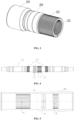
FIG. 1 is a front schematic structural diagram showing an axle sleeve of a gauge-changing wheelset according to an embodiment of the present application; -
FIG. 2 is an axial sectional schematic diagram ofFIG. 1 ; -
FIG. 3 is a perspective schematic structural diagram showing an axle sleeve of a gauge-changing wheelset according to an embodiment of the present application; -
FIG. 4 is a front schematic structural diagram showing an axle of a gauge-changing wheelset according to an embodiment of the present application; -
FIG. 5 is an axial sectional schematic structural diagram of an outer sleeve for a motor vehicle according to an embodiment of the present application; -
FIG. 6 is an axial sectional schematic structural diagram of an outer sleeve for a trailer according to an embodiment of the present application; -
FIG. 7 is an axial sectional schematic structural diagram of a gauge-changing wheelset according to an embodiment of the present application; -
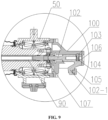
FIG. 8 is an axial sectional schematic structural diagram of another gauge-changing wheelset according to an embodiment of the present application; and -
FIG. 9 is a partial enlarged view of A inFIG. 8 . - 10. axle; 11. outer spline of axle; 12. oblong hole; 13. first raceway; 14. second non-self-locking thread; 15. central through hole; 20. axle sleeve; 21. first non-self-locking thread; 22. outer spline of axle sleeve; 23. sliding bearing mounting groove; 24. wheel mounting base; 25. sliding bearing gland mounting groove; 30. wheel; 40. outer sleeve; 41. second raceway; 42. inner spline; 50. axle-box body; 60. locking slip ring; 70. locking spring; 80. thrust pin; 90. thrust rod; 100. thrust converting mechanism; 101. mounting base; 101-1. base body; 101-2. transition connecting base; 101-3. extending base; 102. jacking shaft; 102-1. jacking portion; 103. positioning pin; 104. preloaded spring; 105. friction block; 106. jacking gland; 107. jacking shaft support ring; 110. sliding bearing; 120. gear box; 130. brake disc; 140. gear box mounting base; 150. brake disc mounting interface.
- Embodiments of the present application are further described in detail below in conjunction with the drawings and embodiments. The following embodiments are intended to illustrate the application, but are not intended to limit the scope of the application.
- In the description of the embodiments of the present application, it is to be noted that the orientation or positional relationships indicated by terms such as "center", "longitudinal", "lateral", "upper", "lower", "front", "rear", "left", "right", "vertical", "horizontal", "top", "bottom", "inside", "outside", etc. are based on the orientation or positional relationship shown in the drawings, and are merely for the convenience of describing the embodiments of the present application and simplifying the description, rather than indicating or implying that the device or component stated must have a particular orientation, is constructed and operated in a particular orientation, and thus is not to be construed as limiting the embodiments of the present application. Moreover, the terms "first", "second", "third", and the like are used for descriptive purposes only and are not to be construed as indicating or implying relative importance.
- In the description of the embodiments of the present application, it is to be noted that unless explicitly stated and defined otherwise, the terms "connected with", and "connected" shall be understood broadly, for example, it may be either fixedly connected or detachably connected, or can be integrated; it may be mechanically connected, or electrically connected; it may be directly connected, or indirectly connected through an intermediate medium. The specific meanings of the terms above in embodiments of the present application can be understood by a person skilled in the art in accordance with specific conditions.
- In the embodiments of this application, unless otherwise clearly stated and defined, the first feature being located "on" or "under" the second feature means that the first feature is in direct contact with the second feature or the first feature is in contact with the second feature by an intervening media. Also, the first feature being located "on", "above" and "on top of" the second feature may mean that the first feature is directly on or above the second feature, or it simply means that the level of the first feature is higher than the second feature. The first feature being located "under", "below" and "on bottom of" the second feature may mean that the first feature is directly under or below the second feature, or it simply means that the level of the first feature is lower than the second feature.
- In the description of this specification, descriptions with reference to the terms "one embodiment", "some embodiments", "examples", "specific examples", or "some examples" etc. mean that specific features, structure, materials or characteristics described in conjunction with the embodiment or example are included in at least one embodiment or example of the embodiments of the present application. In this specification, the schematic expressions of the above terms do not necessarily refer to the same embodiment or example. Also, the described specific features, structures, materials or characteristics can be combined in any one or more embodiments or examples in a suitable manner. In addition, those skilled in the art may integrate and combine the different embodiments or examples and the features of the different embodiments or examples described in this specification without contradicting each other.
- As shown in
FIGS. 1 to 9 , an embodiment of the present application provides a gauge-changing wheel set. - A gauge-change wheelset according to an embodiment of the present application includes an
axle sleeve 20, anouter sleeve 40, anaxle 10, a pair ofwheels 30 and a linkage mechanism. - An outer circumference of a first end of each axle sleeve is provided with a
wheel mounting base 24 having a width consistent with the width of the hub of eachwheel 30, thewheel 30 is fastened on thewheel mounting base 24, and may be in interference fit with thewheel mounting base 24 so as to ensure the reliability of the connection between the two. - An inner circumference of the second end of each
axle sleeve 20 is provided with a section of a first non-self-lockingthread 21. The first non-self-lockingthreads 21 of the pair ofaxle sleeves 20 have opposite directions of rotation, and the pair ofwheels 30 are fastened on thewheel mounting bases 24 of the pair ofaxle sleeves 20. Theaxle 10 is provided with two sections of second non-self-lockingthreads 14 that form a non-self-locking thread pair with the first non-self-lockingthread 21 at intervals, that is, the pair of second non-self-lockingthreads 14 also have opposite directions of rotation. Thewheels 30 are mounted on theaxle 10 through theaxle sleeves 20, and each first non-self-lockingthread 21 is connected with each second non-self-lockingthread 14. - When the pair of
wheels 30 is pushed inward or outward at the same time after thewheels 30 are unloaded, due to the non-self-locking thread pair having opposite direction of rotation, the pair ofwheels 30 may move closer to each other or away from each other when they rotate in the same direction until they move to a set gauge-changing position so as to change the gauge. By arranging theaxle sleeve 20, thewheels 30 can easily slide along theaxle 10 to change the gauge, and the connection structure of theaxle 10 and thewheel 30 is simple, and the gauge-changing reliability is high. - The
axle sleeve 20 engages with the second non-self-lockingthread 14 of theaxle 10 by the first non-self-lockingthread 21 for transmitting part of the torque, and generating relative rotation and lateral movement between theaxle sleeve 20 and theaxle 10 in the unlocked state. - Specifically, the first non-self-locking
thread 21 has a length greater than the length of the second non-self-lockingthread 14, and the length difference is equal to half of the gauge to be changed, so that bothwheels 30 can move half of the gauge to be changed relative to theaxle 10 during the rotation by followingrespective axle sleeves 20, so that a sum of the distances along which bothwheels 30 move is equal to the distance of the desired gauge to be changed. - According to an embodiment of the present application, as shown in
FIG. 1 to FIG. 3 , a slidingbearing mounting groove 23 extending from a first end to a second end of theaxle sleeve 20 at an inner circumference of theaxle sleeve 20 is used for mounting a slidingbearing 110. The slidingbearing mounting groove 23 extends to a position close to the first non-self-lockingthread 21, and has a length equal to a length of the slidingbearing 110. By arranging the slidingbearing 110, it is convenient for theaxle sleeve 20 to slide stably and smoothly and a protective effect on theaxle sleeve 20 is provided. - According to an embodiment of the present application, the inner circumference of the
axle sleeve 20 is provided with a sealing ring mounting groove at the position between the slidingbearing mounting groove 23 and the first non-self-lockingthread 21, and the sealing ring mounting groove is used for mounting the sealing ring so as to seal the end of the slidingbearing 110. - According to an embodiment of the present application, the first end of the
axle sleeve 20 is provided with a sliding bearinggland mounting groove 25 used to mount the sliding bearing gland. A plurality of threaded holes are disposed at the circumferential bottom surface of the sliding bearinggland mounting groove 25 at intervals, so that the sliding bearing gland is fixed in the sliding bearinggland mounting groove 25 by a fastener and the slidingbearing 110 is fixed by the sliding bearing gland. In addition, an inner circumference of the sliding bearing gland is provided with a sealing ring mounting groove for mounting the sealing ring, thereby forming a sealing structure at both ends of the slidingbearing 110 to prevent grease from entering the joint surface of the slidingbearing 110 and theaxle 10. - In order to optimize the structure, according to an embodiment of the present application, the outside of the
axle sleeve 20 has a three-stage stepped shape having a descending diameter from the first end to the second end and thewheel mounting base 24 has the largest diameter and the highest strength, and adjacent steps are connected by arc surface transition so as to avoid stress concentration at the connection between the steps. - Specifically, as shown in
FIG. 4 , an outer circumference of theaxle 10 close to a middle portion thereof is provided with a section of outer spline extending in the axial direction of theaxle 10, and both axial sides of theouter spline 11 of the axle at the outer circumference thereof are provided with a pair of second non-self-lockingthreads 14 having opposite direction of rotation, that is, theaxle 10 is further provided with two sections of second non-self-lockingthread 14 having opposite direction of rotation disposed at both axial sides of theouter spline 11. In an embodiment, there is a space between each section of second non-self-lockingthread 14 and theouter spline 11 of the axle. Theouter spline 11 of theaxle 10 is provided with anoblong hole 12 radially extending through the outer spline. That is, theoblong hole 12 is disposed to coincide with the outer spline, and has a longitudinal direction along the axial direction of the axle, that is, theoblong hole 12 has a longitudinal direction consistent with the extending direction of theouter spline 11 of the axle. - Further, a part of the
axle 20 between one of the second non-self-lockingthreads 14 and theouter spline 11 of the axle is provided with at least onefirst raceway 13 circumferentially disposed around theaxle 10, and thefirst raceway 13 is disposed close to theouter spline 11 of the axle. - In the present embodiment, the
first raceway 13 has a cross section of concave semicircle. - The
outer sleeve 40 is sleeved outside theaxle 10, an inner circumference of theouter sleeve 40 is provided with asecond raceway 41 corresponding to thefirst raceway 13, and thesecond raceway 41 has the same size and shape as those of thefirst raceway 13. That is, thesecond raceway 41 also has a cross section of concave semicircle. Thesecond raceway 41 is provided with a rolling element mounting hole and is snap-fitted with thefirst raceway 13 to form a circular rolling space in which a rolling element is mounted through the rolling element mounting hole. The rolling element, which may be a rolling ball, has an outer diameter matched with an inner diameter of the rolling space. The rolling space is filled with the rolling elements. In order to prevent impurities such as dust from entering the rolling space, a sealing plug is provided at the rolling element mounting hole. By connecting theouter sleeve 40 with theaxle 10 through the rolling element, theouter sleeve 40 is rotatably connected outside theaxle 10, in other words, theouter sleeve 40 has rotational degree of freedom, but is limited in the movement degree of freedom, that is, theouter sleeve 40 can rotate relative to theaxle 10 but cannot move. - The outer circumference of the second end of the
axle sleeve 20 is provided with a section of outer splines extending along its axial direction. After being mounted, the second end of theaxle sleeve 20 is located inside thewheel 30 and faces theouter sleeve 40;inner splines 42 matched with the outer splines on theaxle sleeve 20 are respectively disposed on both axial sides of thesecond raceway 41 45- inside the inner circumference of the outer sleeve and located at a predetermined interval from thesecond raceway 41. Theaxle sleeve 20 and theouter sleeve 40 are connected through theinner splines 42 of theouter sleeve 40 and theouter splines 22 of theaxle sleeve 20 such that theaxle sleeve 20 can rotate together with theouter sleeve 40, or theaxle sleeve 20 can move axially relative to theouter sleeve 40. In the present embodiment, by arranging theaxle sleeve 20, the torque transmission between thewheel 30 and theouter sleeve 40 and the lateral slip between thewheel 30 and theaxle 10 are realized. Theaxle sleeve 20 has a simple and reliable structure, and can be used for the conversion among various gauges. - It should be noted that the "predetermined interval" can be set according to specific needs, and the predetermined interval between the
inner splines 42 on both axial sides of thesecond raceway 41 and thesecond raceway 41 can be different. - The linkage mechanism according to the present embodiment is mounted between the
axle 10 and theouter sleeve 40 for locking or unlocking the rotation of theouter sleeve 40 relative to theaxle 10; and when the rotation of theouter sleeve 40 relative to theaxle 10 is unlocked by the linkage mechanism and thewheels 30 are in an unloaded state, the pair ofwheels 30 are pushed to rotate synchronously such that they move closer to each other or away from each other until the gauge to be changed is reached and thus the gauge is changed. - The gauge-changing wheelset of the present embodiment further includes a
thrust rod 90. A central through hole through which thethrust rod 90 penetrates is provided along the axial direction of theaxle 10. Thethrust rod 90 has an end connected with the linkage mechanism and the other end extending to an outer end of the axle. By applying a thrust to thethrust rod 90, thewheels 30 are unlocked by driving the linkage mechanism through thethrust rod 90. - According to an embodiment, the linkage mechanism includes a locking slip ring 60, a
thrust pin 80 and a locking elastic piece. In an embodiment, the locking slip ring 60 is slidably sleeved at theouter spline 11 of the axle, and the locking slip ring is provided therein with aninner spline 42 matched with theouter spline 11 of the axle, and provided externally with an outer spline matched with theinner spline 42 of theouter sleeve 40. An inner wall of the locking slip ring 60 is radially provided with a pair of open grooves having openings communicated with an end of the locking slip ring 60. Thethrust pin 80 passes through theoblong hole 12 and both ends of thethrust pin 80 extend out of theoblong hole 12, and both ends of thethrust pin 80 exposed outside theoblong hole 12 are embedded inside the pair of the open grooves by the openings of the open grooves. Thethrust pin 80 has a length consistent with a distance between the top walls of the pair of open grooves, and both ends of thethrust pin 80 abut against the top walls of the open groove. In addition, thethrust pin 80 has a width consistent with widths of the open grooves such that thethrust pin 80 and the locking slip ring 60 have reliable connection. - In order to facilitate the axial movement of the
thrust pin 80 along theoblong hole 12, thethrust pin 80 has a width smaller than the length of theoblong hole 12, and a thickness less than or equal to the width of theoblong hole 12. In addition, the width of the locking slip ring 60 should not be too wide to ensure that the locking slip ring 60 can have an amount of movement in the space between thesecond raceway 41 of theouter sleeve 40 and theinner spline 42 of theouter sleeve 40. In addition, theoblong hole 12 should have a length lightly smaller than the length of theouter spline 11 of the axle, so that the locking slip ring 60 always moves on theouter spline 11 of the axle. - The locking elastic piece, for example, an elastic spring 70, is sleeved on the axle, and has an end abutted against an outer wall, i.e., a stop end surface of the
first raceway 13, and the other end abutted against an end of the locking slip ring 60 away from the open groove. When the locking elastic piece is in a natural state, theouter spline 42 outside the locking slip ring 60 is at least partially located in theinner spline 42 of a corresponding side of theouter sleeve 40 to lock the rotation of theouter sleeve 40 for fixing the outer sleeve relative to theaxle 10. In this case, the wheels and theaxle sleeve 20 as well as theouter sleeve 40 and theaxle 10 are integrated and have no rotation relative to each other, and thewheels 30 are in a locked state. - Specifically, an end of the
thrust rod 90 penetrates into the central throughhole 15 of theaxle 10 and abuts against a side of thethrust pin 80 where the open groove is located, and the other end of thethrust rod 90 extends to the end of theaxle 10. By applying a thrust to thethrust rod 90, thethrust rod 90 pushes the locking slip ring 60 to compress the locking elastic element and disengage from theinner splines 42 of theouter sleeve 40 to unlock the rotation of theouter sleeve 40 relative to theaxle 10. - In the present embodiment, the first non-self-locking
thread 21 is a trapezoidal thread, and correspondingly, the second non-self-lockingthread 14 is a trapezoidal thread matching the trapezoidal thread having reliable performance. - It should be noted that the locking elastic piece may also be other elastic sleeves with certain elasticity.
- According to an embodiment of the present application, an inner circumference of the
outer sleeve 40 is provided with an annular boss at thesecond raceway 41 and thesecond raceway 41 is formed on the annular boss. After theouter sleeve 40 and theaxle 10 are connected by a rolling ball, a pair of mounting spaces for theaxle sleeves 20 are formed between theouter sleeve 40 and theaxle 10 at both axial sides of the rolling space. During the sliding process, the slidingbearing 110 is in sliding contact with theaxle 10 and is inserted into theouter sleeve 40 from the mounting space; theouter spline 22 of the axle sleeve move axially relative to theinner spline 42 of theouter sleeve 40 until the first non-self-lockingthread 21 of theaxle 20 is in contact with the second non-self-lockingthread 14 of theaxle 10, then theaxle sleeve 20 is rotated such that the first non-self-lockingthread 21 is screwed into the second non-self-lockingthread 14. - According to an embodiment of the present application, an annular flange is formed at a position of the
axle 10 where thefirst raceway 13 is constructed. The annular flange has an outer diameter larger than the outer diameter of the remaining part of theaxle 10 such that a stop end surface is formed at both axial ends of the annular flange so as to define a limit position at which theaxle sleeve 20 stops moving. - For a gauge-changing wheelset for motor vehicle, a
gearbox 120 is mounted outside theouter sleeve 40, and for a gauge-changing wheelset for trailer, a plurality ofbrake discs 130 are mounted outside theouter sleeve 40. - In order to improve the reliability of the connection between the
outer sleeve 40 and theaxle 10, according to an embodiment of the present application, there are twofirst raceways 13 arranged side by side. Correspondingly, there are twosecond raceways 41, thus forming two raceway spaces arranged side by side. - Further, the
axle 10 is divided into a main half shaft and an auxiliary half shaft by eachfirst raceway 13, and the part of theaxle 10 provided with the outer splines and theoblong hole 12 is the main half shaft. The locking slip ring 60 is mounted on the main half shaft, and the open groove of the locking slip ring 60 faces towards the free end of the main half shaft, and the locking spring 70 is mounted between the stop end surface of the annular flange and the locking slip ring 60. - For optimizing the structure, the
first raceway 13 is disposed close to theouter spline 11 of theaxle 10. - According to an embodiment of the present application, a distance between the
outer splines 11 of the axle and the adjacent second non-self-lockingthreads 14 is equal to a distance between the annular flange and the adjacent second non-self-lockingthreads 14, and both of them are equal to half of the gauge to be changed, and the distance serves as a movement space of the first non-self-lockingthread 21 of theaxle sleeve 20. - As shown in
FIG. 5 , for the gauge-changing wheelset for motor vehicle, theouter sleeve 40 is constructed with agearbox mounting base 140 for mounting thegearbox 120; as shown inFIG. 6 , for the gauge-changing wheelset for trailer, theouter sleeve 40 is constructed with a brakedisc mounting interface 150 and there are a plurality of the brakedisc mounting interfaces 150 arranged at intervals for mounting a plurality ofbrake discs 130 arranged at intervals. - Specifically, both ends of the
axle 10 located outside the pair ofwheels 30 are respectively mounted with axle-box bodies 50. - According to an embodiment of the present application, both axial ends of the
axle 10 are configured as stepped shafts with diameters at both ends smaller than the middle diameter, so that both ends of the stepped shaft are used to mount the axle-box body 50. - According to an embodiment of the present application, sliding sections are respectively formed on the intermediate shaft of the stepped shaft between each section of the second non-self-locking
thread 14 and the shaft end of the intermediate shaft, so that the slidingbearings 110 of theaxle sleeve 20 slides relative to theaxle 10. - In addition, the central through
hole 15 provided on theaxle 10 is beneficial to reduce the weight of theaxle 10. - According to an embodiment of the present application, the gauge-changing wheelset further includes a
thrust converting mechanism 100 capable of directly applying thrust on thethrust rod 90 by means of an external force during changing gauge, and thethrust converting mechanism 100 is mounted an end of theaxle 10 where thethrust rod 90 is located, that is, thethrust converting mechanism 100 only needs to be mounted on an end of theaxle 10. - Specifically, as shown in
FIGS. 8 and9 , thethrust converting mechanism 100 includes a mountingbase 101 and a jackingshaft 102 axially penetrating through the mountingbase 101, the mountingbase 101 is fixedly mounted outside the axle-box body 50, and the jackingshaft 102 is connected to thethrust rod 90. When the track side wall of the ground gauge-changing facility applies an axial thrust to the jackingshaft 102, the jackingshaft 102 pushes thethrust rod 90 to move to unlock thewheel 30. - Specifically, the mounting
base 101 is provided with a horizontal through hole along the axial direction of the axle-box body 50; the jackingshaft 102 penetrates movably through the horizontal through hole, and is opposite to the end of thethrust rod 90 located at the outer end of theaxle 10. An open slot is formed in one of the jackingshaft 102 and the mountingbase 101 at an opposite position of the jackingshaft 102. That is, the open slot may be provided on the radial outer wall of the jackingshaft 102 or may be provided on the corresponding inner wall of the mountingbase 101. - The open slot has an axis perpendicular to the axis of the horizontal through hole. A positioning piece is mounted in the open slot and connected with the open slot by an elastic preloaded piece such that it has an amount of movement along the axis of the open slot; the other one of the jacking
shaft 102 and the mountingbase 101 is provided with a positioning recess. That is, when the jackingshaft 102 is provided with the open slot, the mountingbase 101 is provided with a positioning recess, while when the mountingbase 101 is provided with the open slot, the jackingshaft 102 is provided with a positioning recess. - Further, a positioning end of the positioning piece is matched with the positioning recess. For example, when the positioning end of the positioning piece is a spherical surface, the positioning recess has a matching spherical surface, and the two spherical surfaces are compatible.
- When the positioning end of the positioning piece is located in the positioning recess, the jacking
shaft 102 is in a locked state, and when the positioning end of the positioning piece disengages from the positioning recess due to the jackingshaft 102 being subjected to a lateral thrust, the jackingshaft 102 is in a movable state. Specifically, the lateral thrust acts on the positioning end of the positioning piece, thereby generating a vertical component force, compressing the elastic preloaded piece so that the positioning piece is retracted into the open slot, and the lateral positioning of the jackingshaft 102 is released. In this case, the jackingshaft 102 is in the movable state, and continues to push the jackingshaft 102, which may push thethrust rod 90. - After the axle-
box body 50 is lifted by an unlocking rail to unload thewheel 30, a thrust is applied to thethrust rod 90 through the jackingshaft 102, thethrust rod 90 pushes thethrust pin 80 to drive the locking slip ring 60 to compress the locking elastic piece on theaxle 10 and move away from theinner splines 42 of theouter sleeve 40 to disengage theinner splines 42 of theouter sleeve 40, thereby unlocking the rotational degree of freedom of theouter sleeve 40. In this case, when thewheels 30 are pushed, since theaxle sleeve 20 is connected with theaxle 10 through the non-self-locking thread pair, theouter sleeve 40, thewheel 30 and theaxle sleeve 20 will rotate together around theaxle 10, the first non-self-lockingthread 21 of theaxle sleeve 20 moves along the second non-self-lockingthread 14 of theaxle 10 during the rotation, so that thewheel 30 moves along with theaxle sleeve 20 during the rotation until the gauge is changed. - After the gauge is changed, the ground gauge-changing facility will no longer apply thrust on the jacking
shaft 102, that is, the thrust of thethrust rod 90 on thethrust pin 80 is removed in this case, and thethrust pin 80 will follow the locking slip ring 60 to return to its original position under the elastic reset action of the locking elastic piece, that is, the outer splines of the locking slip ring 60 are re-inserted into theouter splines 22 of theouter sleeve 40 to lock the rotational degree of freedom of theouter sleeve 40. In this case, theaxle sleeve 20 and theouter sleeve 40 cannot rotate relative to theaxle 10, theaxle sleeve 20 and theouter sleeve 40 can only rotate together with theaxle 10, that is, theaxle sleeve 20 and theouter sleeve 40 are locked on theaxle 10, and thewheel 30 is re-locked. - In order to ensure the stability of the jacking
shaft 102 when being pushed, a jackingshaft support ring 107 is fixed at the end of theaxle 10, and is coaxial with the central throughhole 15. The jackingshaft support ring 107 partially extends into the central throughhole 15, so that the jackingshaft support ring 107 can be mounted reliably. The jackingshaft support ring 107 has an inner diameter matching the outer diameter of the jackingshaft 102 so as to ensure that the jackingshaft 102 does not shake during the movement process, the jackingshaft 102 enters the central throughhole 15 through the jackingshaft support ring 107 and pushes thethrust rod 90, and the movement process is smooth. - The gauge-changing wheelset according to the embodiment has convenient and reliable gauge-changing operation, and simple overall structure.
- Further, as shown in
FIG. 8 , the mountingbase 101 includes a base body 101-1 and an extending base 101-3 extending to a side along the base body 101-1, and the base body 101-1 and the extending base 101-3 are connected by a frustum-shaped transition connecting base 101-2 having a large end connected with the base body 101-1 and a small end connected with the extending base 101-3, which can form a reasonable avoidance and match with the ground gauge-changing facility. - Further, a periphery of the base body is provided with connecting holes and the base body 101-1 is mounted on the outer end of the axle-
box body 50 by allowing the connecting pieces to pass through the connecting holes. The horizontal through hole penetrates through the extending base 101-3, the transition connecting base 101-2 and the base body 101-1. Specifically, the extending base 101-3, the transition connecting base 101-2 and the base body 101-1 are integrally formed, which is convenient for processing and leads to high strength. The mountingbase 101 of the present embodiment is directly mounted on the outer end of the axle-box body 50, and can additionally function as the outer end cover of the axle-box body 50. The base body -101-1 has a shape matching the shape of the outer end of the axle-box body 50, for example, can be in a square shape and rounded arcs around the square. - In the present embodiment, the base body 101-1 is plate-shaped, and the extending base 101-3 is cylinder-shaped. The lower side of the extending base 101-3 is provided with a notch penetrating through the end thereof, and the notch can be formed by cutting a side wall corresponding to a sub-arc along the axial direction from the end of the extending base 101-3; the specific cutting length is set based on the length of the desired changing gauge.
- An outer end of the jacking
shaft 102 is flush with an outer end of the extending base 101-3 when the positioning end of the positioning piece is located in the positioning recess; that is, the jackingshaft 102 is movable in the mountingbase 101, specifically the extending base 101-3. The outer end of the jackingshaft 102 is flush with the outer end of the extending base 101-3 during no movement occurs and the jackingshaft 102 moves into the extending base 101-3 along the notch during movement. - Specifically, the jacking portion 102-1 may be subjected to a lateral thrust until the positioning end of the positioning piece disengages from the positioning recess and move along the notch, and the specific movable length is equal to the length of the notch.
- According to an embodiment of the present application, as shown in
FIGS. 8 to 9 , the outer end of the extending base 101-3 is provided with a jackinggland 106 for limiting the position of the jackingshaft 102 to avoid the jackingshaft 102 to extend out of the outer end of the extending base 101-3. - The outer end of the jacking
shaft 102 is provided with a connecting portion extending downward and inclined toward a direction away from the jackinggland 106, the jacking portion 102-1 is formed at a free end of the connecting portion, and is provided with a vertical flat surface. By arranging the jacking portion 102-1 at the lower end of the jackingshaft 102, it is convenient to push the jackingshaft 102 from the bottom of the jackingshaft 102, which on one hand, may reasonably avoid the jackinggland 106, and on the other hand, may adapt to the height of the track side wall of the ground gauge-changing facility. - According to an embodiment of the present application, a
friction block 105 is mounted on the vertical flat surface of the jacking portion 102-1. By arranging thefriction block 105, on one hand, the strength of the jacking portion 102-1 is increased, and on the other hand, the service life of the jacking portion 102-1 is prolonged. In addition, when thefriction block 105 is worn out, it may be directly replaced without replacing the jacking portion 102-1 and mountingbase 101, which saves costs. - According to an embodiment of the present application, the positioning piece is a
positioning pin 103 having a positioning end configured to have a convex arc surface, such as a convex spherical surface, and the positioning recess is configured to have a concave arc surface matched with the convex arc surface, such as a concave spherical surface. A part of the convex arc surface is located in the concave arc surface such that the positioning end can be retracted from the positioning recess in time when it is subjected to a lateral thrust. It should be noted that, when thepositioning pin 103 is subjected to a lateral thrust, its convex arc surface is subjected to a vertical thrust force component and a lateral thrust force component, and the vertical thrust force component compresses the elastic preloaded piece so that thepositioning pin 103 moves downward, and the lateral thrust component pushes thepositioning pin 103 away from the positioning recess. - According to an embodiment of the present application, the elastic preloaded piece is a
preloaded spring 104 having an end fastened in the open slot, and the other end fastened and sleeved on an end of thepositioning pin 103 distal to the positioning end. Thepositioning pin 103 may be provided with a connecting end with a diameter smaller than that of the positioning end. A positioning step is formed at the connection between the connecting end and the positioning end, and thepreloaded spring 104 is directly sleeved on the connecting end and abuts against the positioning step. - According to the present embodiment, the gauge-changing process is described as follows.
- 1. unlocking stage: the axle-
box body 50 is gradually lifted by an unlocking rail, so that thewheel 30 is unloaded. After thethrust converting mechanism 100 is triggered, the jackingshaft 102 is pushed inward to contact thethrust rod 90, and thethrust pin 80 and the locking slip ring 60 are pushed to move inward and compress the locking spring 70 until the locking slip ring 60 is out of contact with theinner splines 42 of theouter sleeve 40, and the rotational constraint between theaxle 10 and theaxle sleeve 20 is released. - 2. gauge-changing stage: after entering the gauge-changing stage, the
wheels 30 move inward (or outward) under the action of the gauge-changing lateral force, and thewheels 30 and theaxle sleeve 20 rotate together around the non-self-locking thread pair to reach a target gauge. - 3. locking stage: after entering the locking section, the unlocking rail gradually lowers and no longer plays the supporting role, and the locking slip ring 60 moves outward under the thrust of the locking spring 70 and is inserted into the
inner spline 42 of theouter sleeve 40 to be re-locked. The jackingshaft 102 recovers under the action of the restoring force of the locking spring 70 and is out of contact with thethrust rod 90, the gauge-changing process ends, the wheelset is completely locked, and the normal operation state is re-entered. - A railway vehicle according to an embodiment of the present application includes a vehicle body and a bogie arranged under the vehicle body, and each bogie is provided with a pair of gauge-changing wheelsets. By arranging the gauge-changing wheelsets on each bogie, the railway vehicle may drive on rails having different gauges.
- The implementations above are only used to illustrate the present application, but not to limit the present application. Although the present application has been described in detail with reference to the embodiments, those skilled in the art should understand that various combinations, modifications, or equivalent replacements of the technical solutions of the present application do not depart from the scope of the technical solutions of the present application provided they are covered by the claims of the present application.
Claims (12)
- A gauge-changing wheelset, comprising an axle (10), a pair of wheels, further comprising a pair of axle sleeves (20), an outer sleeve (40) and a linkage mechanism (60, 70, 80),wherein an outer circumference of a first end of each axle sleeve is provided with a wheel mounting base (24), an outer circumference of a second end of each axle sleeve (20) is provided with a section of an outer spline (22) extending along an axial direction of the axle sleeve, an inner circumference of the second end of each axle sleeve is provided with a section of a first non-self-locking thread (21), a pair of the first non-self-locking threads of the pair of axle sleeves have opposite directions of rotation, and the pair of wheels are fastened on the wheel mounting bases (24) of the pair of axle sleeves;the axle is provided with two sections of second non-self-locking threads (14) at intervals, each second non-self-locking thread forming a non-self-locking thread pair with the first non-self-locking thread (21); the wheels are mounted on the axle through the axle sleeves (20), the first non-self-locking thread is fitted and connected with the second non-self-locking thread, and a part of the axle between the pair of second non-self-locking threads is provided with at least one first raceway (13) circumferentially disposed around the axle;the outer sleeve (40) is sleeved outside the axle, an inner circumference of the outer sleeve is provided with a second raceway (41) corresponding to and being snap-fitted with the first raceway to form a rolling space in which a rolling element matched therewith is mounted such that the outer sleeve is rotatably connected outside the axle, and an inner spline (42) matched with the outer spline (22) on the axle sleeve (20) is provided on both axial sides of the second raceway (41) inside the outer sleeve (40) and located at a predetermined distance from the second raceway; andthe linkage mechanism is mounted between the axle and the outer sleeve (40) for locking or unlocking rotation of the outer sleeve relative to the axle; and when the rotation of the outer sleeve relative to the axle is unlocked by the linkage mechanism and the wheels are in an unloaded state, the pair of wheels are pushed to rotate synchronously to move closer to each other or away from each other, so as to change the gauge.
- The gauge-changing wheelset of claim 1, wherein an outer circumference of the axle close to a middle portion thereof is provided with a section of outer spline (11) extending in an axial direction of the axle, and the outer spline of the axle is provided with an oblong hole (12) radially extending through the outer spline and having a longitudinal direction coinciding with the axial direction of the axle.
- The gauge-changing wheelset of claim 2, wherein the linkage mechanism comprises a locking slip ring (60), a thrust pin (80) and a locking elastic piece (70);
the locking slip ring is slidably sleeved at the outer spline of the axle, and the locking slip ring is provided therein with an inner spline matched with the outer spline of the axle, and provided externally with an outer spline matched with the inner spline of the outer sleeve; an inner wall of the locking slip ring is radially provided with a pair of open grooves having openings communicated with an end of the locking slip ring; the thrust pin passes through the oblong hole, and both ends of the thrust pin extend out of the oblong hole and both ends of the thrust pin exposed outside the oblong hole are embedded inside the pair of the open grooves by the openings of the open grooves; the locking elastic piece is sleeved on the axle, and has an end abutted against an outer wall of the first raceway, and another end abutted against an end of the locking slip ring away from the open groove; and when the locking elastic piece is in a natural state, the outer spline outside the locking slip ring is at least partially located in the inner spline of a corresponding side of the outer sleeve to lock the rotation of the outer sleeve. - The gauge-changing wheelset of claim 3, wherein the gauge-changing wheelset further comprises a thrust rod (90) penetrating through a central through hole provided along the axial direction of the axle, an end of the thrust rod penetrates through the central through hole (15) of the axle and abuts against a side of the thrust pin (80) at which the open groove is located, and another end of the thrust rod extends to an end portion of the axle; the thrust rod pushes the locking slip ring (60) to compress the locking elastic piece (70) and disengage from the inner spline of the outer sleeve by applying thrust to the thrust rod, so as to unlock the rotation of the outer sleeve relative to the axle.
- The gauge-changing wheelset of claim 3, whereinthe first non-self-locking thread (21) has a length greater than the length of the second non-self-locking thread (14) and equal to half of the gauge to be changed;an inner circumference of the outer sleeve is provided with an annular boss at the second raceway, and after the outer sleeve is connected to the axle, a pair of mounting spaces for the axle sleeves are formed between the outer sleeve and the axle at both axial sides of the rolling space;the second raceway is provided with a rolling element mounting hole through which the rolling element is mounted in the rolling space; andthe locking elastic piece (70) is a locking spring.
- The gauge-changing wheelset of claim 4, further comprising a thrust converting mechanism (100), and axle-box bodies mounted at both ends of the axle and outside the wheels;the thrust converting mechanism comprises a mounting base (101) and a jacking shaft (102), wherein the mounting base is mounted on an outer end of the axle-box body close to an end of the thrust rod (90), and is provided with a horizontal through hole along the axial direction of each axle-box body;the jacking shaft is movably inserted in the horizontal through hole and is opposite to the thrust rod, and an open slot is provided in one of the jacking shaft and the mounting base at an opposite position of the jacking shaft to the mounting base and has an axis perpendicular to the axis of the horizontal through hole; a positioning piece is mounted in the open slot and connected with the open slot by an elastic preloaded piece; the other one of the jacking shaft and the mounting base is provided with a positioning recess matched with a positioning end of the positioning piece; andthe positioning end of the positioning piece is located in the positioning recess and when the jacking shaft is in a locked state, the jacking shaft is pushed so that the positioning end of the positioning piece disengages from the positioning recess, to allow the jacking shaft to be in a movable state to push the thrust rod.
- The gauge-changing wheelset of claim 6, wherein the mounting base comprises a base body (101-1) and an extending base (101-3) extending to a side along the base body, and the base body and the extending base are connected to each other by a frustum-shaped transition connecting base (101-2) having a large end connected with the base body and a small end connected with the extending base, and a periphery of the base body is provided with connecting holes and the horizontal through hole penetrates through the extending base, the transition connecting base and the base body.
- The gauge-changing wheelset of claim 7, wherein a lower side of the extending base is provided with a notch penetrating through an end thereof;a jacking portion (102-1) extends downward from an outer end of the jacking shaft, and the outer end of the jacking shaft is flush with an outer end of the extending base when the positioning end of the positioning piece is located in the positioning recess; andwhen the jacking portion is pushed, the positioning end of the positioning piece disengages from the positioning recess and moves along the notch.
- The gauge-changing wheelset of claim 8, wherein the outer end of the extending base is provided with a jacking gland (106);the outer end of the jacking shaft is provided with a connecting portion extending downward and inclined toward a direction away from the jacking gland, and the jacking portion is formed at a free end of the connecting portion, and is provided with a vertical flat surface; anda friction block is mounted on the vertical flat surface of the jacking portion.
- The gauge-changing wheelset of any one of claims 6 to 9, wherein the positioning piece is a positioning pin (103) having a positioning end configured to have a convex arc surface, and the positioning recess is configured to have a concave arc surface matched with the convex arc surface; and a part of the convex arc surface is located in the concave arc surface; and
the elastic preloaded piece is a preloaded spring having an end fastened in the open slot, and the other end fastened and sleeved on an end of the positioning pin distal to the positioning end. - The gauge-changing wheelset of any one of claims 6 to 9, wherein a jacking shaft support ring is fixed at the end of the axle and is disposed coaxially with the central through hole (15); the jacking shaft support ring partially extends inside the central through hole and has an inner diameter matched with an outer diameter of the jacking shaft; and the jacking shaft enters the central through hole through the jacking shaft support ring and is configured to push the thrust rod.
- A railway vehicle, comprising a vehicle body and a bogie arranged under the vehicle body, wherein each bogie is provided with a pair of gauge-changing wheelsets according to any one of claims 1 to 11.
Applications Claiming Priority (2)
| Application Number | Priority Date | Filing Date | Title |
|---|---|---|---|
| CN202010737192.XA CN111806499B (en) | 2020-07-28 | 2020-07-28 | Variable gauge wheelsets and rail vehicles |
| PCT/CN2021/076579 WO2022021843A1 (en) | 2020-07-28 | 2021-02-10 | Gauge-variable wheelset and rail vehicle |
Publications (3)
| Publication Number | Publication Date |
|---|---|
| EP4056447A1 EP4056447A1 (en) | 2022-09-14 |
| EP4056447A4 EP4056447A4 (en) | 2023-07-05 |
| EP4056447B1 true EP4056447B1 (en) | 2024-12-11 |
Family
ID=72864234
Family Applications (1)
| Application Number | Title | Priority Date | Filing Date |
|---|---|---|---|
| EP21851372.9A Active EP4056447B1 (en) | 2020-07-28 | 2021-02-10 | Gauge-variable wheelset and rail vehicle |
Country Status (4)
| Country | Link |
|---|---|
| EP (1) | EP4056447B1 (en) |
| CN (1) | CN111806499B (en) |
| ES (1) | ES3004659T3 (en) |
| WO (1) | WO2022021843A1 (en) |
Families Citing this family (3)
| Publication number | Priority date | Publication date | Assignee | Title |
|---|---|---|---|---|
| CN111806499B (en) * | 2020-07-28 | 2021-05-11 | 中车青岛四方机车车辆股份有限公司 | Variable gauge wheelsets and rail vehicles |
| CN115362792B (en) * | 2022-09-22 | 2024-04-30 | 中国烟草总公司重庆市公司巫山分公司 | Perforating device for tobacco planting |
| CN116104602B (en) * | 2023-02-28 | 2024-04-12 | 中国空气动力研究与发展中心空天技术研究所 | Force transmission mechanism for engine compressor deflation |
Family Cites Families (10)
| Publication number | Priority date | Publication date | Assignee | Title |
|---|---|---|---|---|
| DE235085C (en) * | 1909-12-04 | 1911-05-30 | WHEEL AXLE WITH VERSATILE TRACK | |
| FR849826A (en) * | 1938-10-11 | 1939-12-02 | Esslingen Maschf | Device for modifying the wheel spacing of a vehicle, in particular the wheels of railway wagons |
| DE737575C (en) * | 1938-10-11 | 1943-07-24 | Esslingen Maschf | Automatic re-gauging device for railway vehicles |
| FR1529679A (en) * | 1967-03-31 | 1968-06-21 | Electro-mechanical variable gauge axle device for passenger cars and freight wagons | |
| CH490214A (en) * | 1969-03-12 | 1970-05-15 | Const Mecaniques De Vervey S A | Railway installation |
| CH502913A (en) * | 1969-12-02 | 1971-02-15 | Vevey Atel Const Mec | Railway installation |
| ES2021919A6 (en) * | 1990-01-04 | 1991-11-16 | Pinto Silva Julio | Gauge changer for railway vehicles having wheel sets, with wheels that are towed or powered by engines arranged transverse to the axis of the vehicle |
| CN202358119U (en) * | 2011-12-18 | 2012-08-01 | 徐州矿山设备制造有限公司 | Tractor rail-changing wheel |
| CN109572740B (en) * | 2018-10-18 | 2024-06-21 | 舍弗勒技术股份两合公司 | Variable gauge axle system and rail vehicle |
| CN111806499B (en) * | 2020-07-28 | 2021-05-11 | 中车青岛四方机车车辆股份有限公司 | Variable gauge wheelsets and rail vehicles |
-
2020
- 2020-07-28 CN CN202010737192.XA patent/CN111806499B/en active Active
-
2021
- 2021-02-10 ES ES21851372T patent/ES3004659T3/en active Active
- 2021-02-10 EP EP21851372.9A patent/EP4056447B1/en active Active
- 2021-02-10 WO PCT/CN2021/076579 patent/WO2022021843A1/en not_active Ceased
Also Published As
| Publication number | Publication date |
|---|---|
| EP4056447A4 (en) | 2023-07-05 |
| ES3004659T3 (en) | 2025-03-12 |
| CN111806499B (en) | 2021-05-11 |
| CN111806499A (en) | 2020-10-23 |
| WO2022021843A1 (en) | 2022-02-03 |
| EP4056447A1 (en) | 2022-09-14 |
Similar Documents
| Publication | Publication Date | Title |
|---|---|---|
| EP4056447B1 (en) | Gauge-variable wheelset and rail vehicle | |
| JP7036932B2 (en) | High-speed train variable gauge trolley for track vehicles | |
| CN108622127B (en) | A variable gauge wheelset | |
| WO2020001097A1 (en) | Wheel set used for variable gauge bogie and bogie | |
| CN108909354B (en) | Locking mechanism for track-variable wheel set and track-variable wheel set | |
| CN111137320B (en) | Variable-track-pitch bogie and track pitch changing method thereof | |
| EP4032778B1 (en) | Wheel mounting bushing for variable-gauge wheelset, and variable-gauge wheelset | |
| CN108583607A (en) | A kind of trailer gauge-changeable bogie used for rail vehicle | |
| CN108909762A (en) | A kind of rail vehicle gauge-changeable bogie wheel pair and bogie | |
| EP4043315B1 (en) | Thrust conversion mechanism for gauge-variable wheel set, unlocking device, and gauge-variable wheel set | |
| EP4190666B1 (en) | Axle for use in gauge-changeable wheel set, and gauge-changeable wheel set | |
| CN111806501B (en) | Unlocking mechanism for gauge wheelset, gauge wheelset and ground track change facility | |
| RU2785611C1 (en) | Variable gauge wheels and railway vehicle | |
| RU2785735C1 (en) | Axle load conversion mechanism for variable track wheelset, release device and variable track wheelsset | |
| CN115195346B (en) | A wheel set for a variable gauge bogie | |
| CN111806496A (en) | Unlocking mechanism for gauge wheelset, gauge wheelset and ground track change facility | |
| RU2781114C1 (en) | Clutch for installing the wheel pair with the possibility of changing the track wheel and the wheels pair with the possibility of changing the track | |
| CN111806498B (en) | Thrust conversion mechanism, unlocking device, track-pitch-variable wheel pair and ground track-changing facility | |
| CN111806495B (en) | Variable gauge wheelsets and rail vehicles | |
| CN111137318A (en) | Locking device of variable-gauge bogie | |
| CN120646045A (en) | Axle non-rotating variable gauge wheel set, bogie and railway vehicle |
Legal Events
| Date | Code | Title | Description |
|---|---|---|---|
| STAA | Information on the status of an ep patent application or granted ep patent |
Free format text: STATUS: THE INTERNATIONAL PUBLICATION HAS BEEN MADE |
|
| PUAI | Public reference made under article 153(3) epc to a published international application that has entered the european phase |
Free format text: ORIGINAL CODE: 0009012 |
|
| STAA | Information on the status of an ep patent application or granted ep patent |
Free format text: STATUS: REQUEST FOR EXAMINATION WAS MADE |
|
| 17P | Request for examination filed |
Effective date: 20220609 |
|
| AK | Designated contracting states |
Kind code of ref document: A1 Designated state(s): AL AT BE BG CH CY CZ DE DK EE ES FI FR GB GR HR HU IE IS IT LI LT LU LV MC MK MT NL NO PL PT RO RS SE SI SK SM TR |
|
| A4 | Supplementary search report drawn up and despatched |
Effective date: 20230607 |
|
| RIC1 | Information provided on ipc code assigned before grant |
Ipc: B61F 7/00 20060101AFI20230601BHEP |
|
| DAV | Request for validation of the european patent (deleted) | ||
| DAX | Request for extension of the european patent (deleted) | ||
| GRAP | Despatch of communication of intention to grant a patent |
Free format text: ORIGINAL CODE: EPIDOSNIGR1 |
|
| STAA | Information on the status of an ep patent application or granted ep patent |
Free format text: STATUS: GRANT OF PATENT IS INTENDED |
|
| INTG | Intention to grant announced |
Effective date: 20240129 |
|
| GRAS | Grant fee paid |
Free format text: ORIGINAL CODE: EPIDOSNIGR3 |
|
| GRAJ | Information related to disapproval of communication of intention to grant by the applicant or resumption of examination proceedings by the epo deleted |
Free format text: ORIGINAL CODE: EPIDOSDIGR1 |
|
| GRAL | Information related to payment of fee for publishing/printing deleted |
Free format text: ORIGINAL CODE: EPIDOSDIGR3 |
|
| STAA | Information on the status of an ep patent application or granted ep patent |
Free format text: STATUS: REQUEST FOR EXAMINATION WAS MADE |
|
| INTC | Intention to grant announced (deleted) | ||
| GRAP | Despatch of communication of intention to grant a patent |
Free format text: ORIGINAL CODE: EPIDOSNIGR1 |
|
| STAA | Information on the status of an ep patent application or granted ep patent |
Free format text: STATUS: GRANT OF PATENT IS INTENDED |
|
| INTG | Intention to grant announced |
Effective date: 20241011 |
|
| GRAA | (expected) grant |
Free format text: ORIGINAL CODE: 0009210 |
|
| STAA | Information on the status of an ep patent application or granted ep patent |
Free format text: STATUS: THE PATENT HAS BEEN GRANTED |
|
| AK | Designated contracting states |
Kind code of ref document: B1 Designated state(s): AL AT BE BG CH CY CZ DE DK EE ES FI FR GB GR HR HU IE IS IT LI LT LU LV MC MK MT NL NO PL PT RO RS SE SI SK SM TR |
|
| REG | Reference to a national code |
Ref country code: GB Ref legal event code: FG4D |
|
| REG | Reference to a national code |
Ref country code: CH Ref legal event code: EP |
|
| REG | Reference to a national code |
Ref country code: IE Ref legal event code: FG4D |
|
| REG | Reference to a national code |
Ref country code: DE Ref legal event code: R096 Ref document number: 602021023384 Country of ref document: DE |
|
| REG | Reference to a national code |
Ref country code: ES Ref legal event code: FG2A Ref document number: 3004659 Country of ref document: ES Kind code of ref document: T3 Effective date: 20250312 |
|
| REG | Reference to a national code |
Ref country code: LT Ref legal event code: MG9D |
|
| PG25 | Lapsed in a contracting state [announced via postgrant information from national office to epo] |
Ref country code: HR Free format text: LAPSE BECAUSE OF FAILURE TO SUBMIT A TRANSLATION OF THE DESCRIPTION OR TO PAY THE FEE WITHIN THE PRESCRIBED TIME-LIMIT Effective date: 20241211 |
|
| PG25 | Lapsed in a contracting state [announced via postgrant information from national office to epo] |
Ref country code: FI Free format text: LAPSE BECAUSE OF FAILURE TO SUBMIT A TRANSLATION OF THE DESCRIPTION OR TO PAY THE FEE WITHIN THE PRESCRIBED TIME-LIMIT Effective date: 20241211 |
|
| PG25 | Lapsed in a contracting state [announced via postgrant information from national office to epo] |
Ref country code: BG Free format text: LAPSE BECAUSE OF FAILURE TO SUBMIT A TRANSLATION OF THE DESCRIPTION OR TO PAY THE FEE WITHIN THE PRESCRIBED TIME-LIMIT Effective date: 20241211 |
|
| REG | Reference to a national code |
Ref country code: NL Ref legal event code: MP Effective date: 20241211 |
|
| PG25 | Lapsed in a contracting state [announced via postgrant information from national office to epo] |
Ref country code: NO Free format text: LAPSE BECAUSE OF FAILURE TO SUBMIT A TRANSLATION OF THE DESCRIPTION OR TO PAY THE FEE WITHIN THE PRESCRIBED TIME-LIMIT Effective date: 20250311 |
|
| PG25 | Lapsed in a contracting state [announced via postgrant information from national office to epo] |
Ref country code: LV Free format text: LAPSE BECAUSE OF FAILURE TO SUBMIT A TRANSLATION OF THE DESCRIPTION OR TO PAY THE FEE WITHIN THE PRESCRIBED TIME-LIMIT Effective date: 20241211 Ref country code: GR Free format text: LAPSE BECAUSE OF FAILURE TO SUBMIT A TRANSLATION OF THE DESCRIPTION OR TO PAY THE FEE WITHIN THE PRESCRIBED TIME-LIMIT Effective date: 20250312 |
|
| PG25 | Lapsed in a contracting state [announced via postgrant information from national office to epo] |
Ref country code: RS Free format text: LAPSE BECAUSE OF FAILURE TO SUBMIT A TRANSLATION OF THE DESCRIPTION OR TO PAY THE FEE WITHIN THE PRESCRIBED TIME-LIMIT Effective date: 20250311 |
|
| PG25 | Lapsed in a contracting state [announced via postgrant information from national office to epo] |
Ref country code: NL Free format text: LAPSE BECAUSE OF FAILURE TO SUBMIT A TRANSLATION OF THE DESCRIPTION OR TO PAY THE FEE WITHIN THE PRESCRIBED TIME-LIMIT Effective date: 20241211 |
|
| REG | Reference to a national code |
Ref country code: AT Ref legal event code: MK05 Ref document number: 1750193 Country of ref document: AT Kind code of ref document: T Effective date: 20241211 |
|
| PG25 | Lapsed in a contracting state [announced via postgrant information from national office to epo] |
Ref country code: SM Free format text: LAPSE BECAUSE OF FAILURE TO SUBMIT A TRANSLATION OF THE DESCRIPTION OR TO PAY THE FEE WITHIN THE PRESCRIBED TIME-LIMIT Effective date: 20241211 |
|
| PG25 | Lapsed in a contracting state [announced via postgrant information from national office to epo] |
Ref country code: PL Free format text: LAPSE BECAUSE OF FAILURE TO SUBMIT A TRANSLATION OF THE DESCRIPTION OR TO PAY THE FEE WITHIN THE PRESCRIBED TIME-LIMIT Effective date: 20241211 |
|
| PG25 | Lapsed in a contracting state [announced via postgrant information from national office to epo] |
Ref country code: IS Free format text: LAPSE BECAUSE OF FAILURE TO SUBMIT A TRANSLATION OF THE DESCRIPTION OR TO PAY THE FEE WITHIN THE PRESCRIBED TIME-LIMIT Effective date: 20250411 |
|
| PG25 | Lapsed in a contracting state [announced via postgrant information from national office to epo] |
Ref country code: PT Free format text: LAPSE BECAUSE OF FAILURE TO SUBMIT A TRANSLATION OF THE DESCRIPTION OR TO PAY THE FEE WITHIN THE PRESCRIBED TIME-LIMIT Effective date: 20250411 |
|
| PG25 | Lapsed in a contracting state [announced via postgrant information from national office to epo] |
Ref country code: EE Free format text: LAPSE BECAUSE OF FAILURE TO SUBMIT A TRANSLATION OF THE DESCRIPTION OR TO PAY THE FEE WITHIN THE PRESCRIBED TIME-LIMIT Effective date: 20241211 |
|
| PG25 | Lapsed in a contracting state [announced via postgrant information from national office to epo] |
Ref country code: AT Free format text: LAPSE BECAUSE OF FAILURE TO SUBMIT A TRANSLATION OF THE DESCRIPTION OR TO PAY THE FEE WITHIN THE PRESCRIBED TIME-LIMIT Effective date: 20241211 Ref country code: RO Free format text: LAPSE BECAUSE OF FAILURE TO SUBMIT A TRANSLATION OF THE DESCRIPTION OR TO PAY THE FEE WITHIN THE PRESCRIBED TIME-LIMIT Effective date: 20241211 |
|
| PG25 | Lapsed in a contracting state [announced via postgrant information from national office to epo] |
Ref country code: SK Free format text: LAPSE BECAUSE OF FAILURE TO SUBMIT A TRANSLATION OF THE DESCRIPTION OR TO PAY THE FEE WITHIN THE PRESCRIBED TIME-LIMIT Effective date: 20241211 |
|
| PG25 | Lapsed in a contracting state [announced via postgrant information from national office to epo] |
Ref country code: CZ Free format text: LAPSE BECAUSE OF FAILURE TO SUBMIT A TRANSLATION OF THE DESCRIPTION OR TO PAY THE FEE WITHIN THE PRESCRIBED TIME-LIMIT Effective date: 20241211 |
|
| PG25 | Lapsed in a contracting state [announced via postgrant information from national office to epo] |
Ref country code: IT Free format text: LAPSE BECAUSE OF FAILURE TO SUBMIT A TRANSLATION OF THE DESCRIPTION OR TO PAY THE FEE WITHIN THE PRESCRIBED TIME-LIMIT Effective date: 20241211 |
|
| PG25 | Lapsed in a contracting state [announced via postgrant information from national office to epo] |
Ref country code: SE Free format text: LAPSE BECAUSE OF FAILURE TO SUBMIT A TRANSLATION OF THE DESCRIPTION OR TO PAY THE FEE WITHIN THE PRESCRIBED TIME-LIMIT Effective date: 20241211 |
|
| REG | Reference to a national code |
Ref country code: DE Ref legal event code: R097 Ref document number: 602021023384 Country of ref document: DE |
|
| PG25 | Lapsed in a contracting state [announced via postgrant information from national office to epo] |
Ref country code: MC Free format text: LAPSE BECAUSE OF FAILURE TO SUBMIT A TRANSLATION OF THE DESCRIPTION OR TO PAY THE FEE WITHIN THE PRESCRIBED TIME-LIMIT Effective date: 20241211 |
|
| REG | Reference to a national code |
Ref country code: CH Ref legal event code: PL |
|
| PG25 | Lapsed in a contracting state [announced via postgrant information from national office to epo] |
Ref country code: DK Free format text: LAPSE BECAUSE OF FAILURE TO SUBMIT A TRANSLATION OF THE DESCRIPTION OR TO PAY THE FEE WITHIN THE PRESCRIBED TIME-LIMIT Effective date: 20241211 |
|
| PG25 | Lapsed in a contracting state [announced via postgrant information from national office to epo] |
Ref country code: LU Free format text: LAPSE BECAUSE OF NON-PAYMENT OF DUE FEES Effective date: 20250210 |
|
| PLBE | No opposition filed within time limit |
Free format text: ORIGINAL CODE: 0009261 |
|
| STAA | Information on the status of an ep patent application or granted ep patent |
Free format text: STATUS: NO OPPOSITION FILED WITHIN TIME LIMIT |
|
| PG25 | Lapsed in a contracting state [announced via postgrant information from national office to epo] |
Ref country code: CH Free format text: LAPSE BECAUSE OF NON-PAYMENT OF DUE FEES Effective date: 20250228 |
|
| 26N | No opposition filed |
Effective date: 20250912 |
|
| GBPC | Gb: european patent ceased through non-payment of renewal fee |
Effective date: 20250311 |
|
| REG | Reference to a national code |
Ref country code: BE Ref legal event code: MM Effective date: 20250228 |
|
| PG25 | Lapsed in a contracting state [announced via postgrant information from national office to epo] |
Ref country code: GB Free format text: LAPSE BECAUSE OF NON-PAYMENT OF DUE FEES Effective date: 20250311 |
|
| PGFP | Annual fee paid to national office [announced via postgrant information from national office to epo] |
Ref country code: FR Payment date: 20251201 Year of fee payment: 6 |
|
| PG25 | Lapsed in a contracting state [announced via postgrant information from national office to epo] |
Ref country code: BE Free format text: LAPSE BECAUSE OF NON-PAYMENT OF DUE FEES Effective date: 20250228 |
|
| PG25 | Lapsed in a contracting state [announced via postgrant information from national office to epo] |
Ref country code: IE Free format text: LAPSE BECAUSE OF NON-PAYMENT OF DUE FEES Effective date: 20250210 |
|
| PGFP | Annual fee paid to national office [announced via postgrant information from national office to epo] |
Ref country code: ES Payment date: 20260319 Year of fee payment: 6 |
|
| PGFP | Annual fee paid to national office [announced via postgrant information from national office to epo] |
Ref country code: DE Payment date: 20260217 Year of fee payment: 6 |