EP4056437A1 - Driving control apparatus for vehicle - Google Patents
Driving control apparatus for vehicle Download PDFInfo
- Publication number
- EP4056437A1 EP4056437A1 EP21212906.8A EP21212906A EP4056437A1 EP 4056437 A1 EP4056437 A1 EP 4056437A1 EP 21212906 A EP21212906 A EP 21212906A EP 4056437 A1 EP4056437 A1 EP 4056437A1
- Authority
- EP
- European Patent Office
- Prior art keywords
- vehicle
- torque request
- control apparatus
- road surface
- driving control
- Prior art date
- Legal status (The legal status is an assumption and is not a legal conclusion. Google has not performed a legal analysis and makes no representation as to the accuracy of the status listed.)
- Granted
Links
Images


Classifications
-
- B—PERFORMING OPERATIONS; TRANSPORTING
- B60—VEHICLES IN GENERAL
- B60W—CONJOINT CONTROL OF VEHICLE SUB-UNITS OF DIFFERENT TYPE OR DIFFERENT FUNCTION; CONTROL SYSTEMS SPECIALLY ADAPTED FOR HYBRID VEHICLES; ROAD VEHICLE DRIVE CONTROL SYSTEMS FOR PURPOSES NOT RELATED TO THE CONTROL OF A PARTICULAR SUB-UNIT
- B60W10/00—Conjoint control of vehicle sub-units of different type or different function
- B60W10/04—Conjoint control of vehicle sub-units of different type or different function including control of propulsion units
- B60W10/06—Conjoint control of vehicle sub-units of different type or different function including control of propulsion units including control of combustion engines
-
- B—PERFORMING OPERATIONS; TRANSPORTING
- B60—VEHICLES IN GENERAL
- B60W—CONJOINT CONTROL OF VEHICLE SUB-UNITS OF DIFFERENT TYPE OR DIFFERENT FUNCTION; CONTROL SYSTEMS SPECIALLY ADAPTED FOR HYBRID VEHICLES; ROAD VEHICLE DRIVE CONTROL SYSTEMS FOR PURPOSES NOT RELATED TO THE CONTROL OF A PARTICULAR SUB-UNIT
- B60W10/00—Conjoint control of vehicle sub-units of different type or different function
- B60W10/02—Conjoint control of vehicle sub-units of different type or different function including control of driveline clutches
-
- B—PERFORMING OPERATIONS; TRANSPORTING
- B60—VEHICLES IN GENERAL
- B60W—CONJOINT CONTROL OF VEHICLE SUB-UNITS OF DIFFERENT TYPE OR DIFFERENT FUNCTION; CONTROL SYSTEMS SPECIALLY ADAPTED FOR HYBRID VEHICLES; ROAD VEHICLE DRIVE CONTROL SYSTEMS FOR PURPOSES NOT RELATED TO THE CONTROL OF A PARTICULAR SUB-UNIT
- B60W10/00—Conjoint control of vehicle sub-units of different type or different function
- B60W10/18—Conjoint control of vehicle sub-units of different type or different function including control of braking systems
- B60W10/184—Conjoint control of vehicle sub-units of different type or different function including control of braking systems with wheel brakes
-
- B—PERFORMING OPERATIONS; TRANSPORTING
- B60—VEHICLES IN GENERAL
- B60W—CONJOINT CONTROL OF VEHICLE SUB-UNITS OF DIFFERENT TYPE OR DIFFERENT FUNCTION; CONTROL SYSTEMS SPECIALLY ADAPTED FOR HYBRID VEHICLES; ROAD VEHICLE DRIVE CONTROL SYSTEMS FOR PURPOSES NOT RELATED TO THE CONTROL OF A PARTICULAR SUB-UNIT
- B60W30/00—Purposes of road vehicle drive control systems not related to the control of a particular sub-unit, e.g. of systems using conjoint control of vehicle sub-units
- B60W30/14—Adaptive cruise control
- B60W30/16—Control of distance between vehicles, e.g. keeping a distance to preceding vehicle
- B60W30/17—Control of distance between vehicles, e.g. keeping a distance to preceding vehicle with provision for special action when the preceding vehicle comes to a halt, e.g. stop and go
-
- B—PERFORMING OPERATIONS; TRANSPORTING
- B60—VEHICLES IN GENERAL
- B60W—CONJOINT CONTROL OF VEHICLE SUB-UNITS OF DIFFERENT TYPE OR DIFFERENT FUNCTION; CONTROL SYSTEMS SPECIALLY ADAPTED FOR HYBRID VEHICLES; ROAD VEHICLE DRIVE CONTROL SYSTEMS FOR PURPOSES NOT RELATED TO THE CONTROL OF A PARTICULAR SUB-UNIT
- B60W40/00—Estimation or calculation of non-directly measurable driving parameters for road vehicle drive control systems not related to the control of a particular sub unit, e.g. by using mathematical models
- B60W40/10—Estimation or calculation of non-directly measurable driving parameters for road vehicle drive control systems not related to the control of a particular sub unit, e.g. by using mathematical models related to vehicle motion
- B60W40/11—Pitch movement
-
- B—PERFORMING OPERATIONS; TRANSPORTING
- B60—VEHICLES IN GENERAL
- B60W—CONJOINT CONTROL OF VEHICLE SUB-UNITS OF DIFFERENT TYPE OR DIFFERENT FUNCTION; CONTROL SYSTEMS SPECIALLY ADAPTED FOR HYBRID VEHICLES; ROAD VEHICLE DRIVE CONTROL SYSTEMS FOR PURPOSES NOT RELATED TO THE CONTROL OF A PARTICULAR SUB-UNIT
- B60W2510/00—Input parameters relating to a particular sub-units
- B60W2510/06—Combustion engines, Gas turbines
- B60W2510/0657—Engine torque
-
- B—PERFORMING OPERATIONS; TRANSPORTING
- B60—VEHICLES IN GENERAL
- B60W—CONJOINT CONTROL OF VEHICLE SUB-UNITS OF DIFFERENT TYPE OR DIFFERENT FUNCTION; CONTROL SYSTEMS SPECIALLY ADAPTED FOR HYBRID VEHICLES; ROAD VEHICLE DRIVE CONTROL SYSTEMS FOR PURPOSES NOT RELATED TO THE CONTROL OF A PARTICULAR SUB-UNIT
- B60W2510/00—Input parameters relating to a particular sub-units
- B60W2510/18—Braking system
- B60W2510/182—Brake pressure, e.g. of fluid or between pad and disc
-
- B—PERFORMING OPERATIONS; TRANSPORTING
- B60—VEHICLES IN GENERAL
- B60W—CONJOINT CONTROL OF VEHICLE SUB-UNITS OF DIFFERENT TYPE OR DIFFERENT FUNCTION; CONTROL SYSTEMS SPECIALLY ADAPTED FOR HYBRID VEHICLES; ROAD VEHICLE DRIVE CONTROL SYSTEMS FOR PURPOSES NOT RELATED TO THE CONTROL OF A PARTICULAR SUB-UNIT
- B60W2520/00—Input parameters relating to overall vehicle dynamics
- B60W2520/16—Pitch
-
- B—PERFORMING OPERATIONS; TRANSPORTING
- B60—VEHICLES IN GENERAL
- B60W—CONJOINT CONTROL OF VEHICLE SUB-UNITS OF DIFFERENT TYPE OR DIFFERENT FUNCTION; CONTROL SYSTEMS SPECIALLY ADAPTED FOR HYBRID VEHICLES; ROAD VEHICLE DRIVE CONTROL SYSTEMS FOR PURPOSES NOT RELATED TO THE CONTROL OF A PARTICULAR SUB-UNIT
- B60W2540/00—Input parameters relating to occupants
- B60W2540/12—Brake pedal position
-
- B—PERFORMING OPERATIONS; TRANSPORTING
- B60—VEHICLES IN GENERAL
- B60W—CONJOINT CONTROL OF VEHICLE SUB-UNITS OF DIFFERENT TYPE OR DIFFERENT FUNCTION; CONTROL SYSTEMS SPECIALLY ADAPTED FOR HYBRID VEHICLES; ROAD VEHICLE DRIVE CONTROL SYSTEMS FOR PURPOSES NOT RELATED TO THE CONTROL OF A PARTICULAR SUB-UNIT
- B60W2552/00—Input parameters relating to infrastructure
- B60W2552/15—Road slope, i.e. the inclination of a road segment in the longitudinal direction
-
- B—PERFORMING OPERATIONS; TRANSPORTING
- B60—VEHICLES IN GENERAL
- B60W—CONJOINT CONTROL OF VEHICLE SUB-UNITS OF DIFFERENT TYPE OR DIFFERENT FUNCTION; CONTROL SYSTEMS SPECIALLY ADAPTED FOR HYBRID VEHICLES; ROAD VEHICLE DRIVE CONTROL SYSTEMS FOR PURPOSES NOT RELATED TO THE CONTROL OF A PARTICULAR SUB-UNIT
- B60W2554/00—Input parameters relating to objects
- B60W2554/80—Spatial relation or speed relative to objects
- B60W2554/802—Longitudinal distance
Definitions
- the present invention relates to driving control apparatuses for vehicles, and in particular, relates to a driving control apparatus for a vehicle having an automatic braking function.
- Driving control apparatuses for vehicles having automatic braking functions for example, driving control apparatuses having full speed range ACC functions, decelerate a vehicle to a stop by operating automatic braking when the vehicle approaches a vehicle ahead that decelerated to a stop or when a vehicle ahead as a target of following cruise has decelerated to a stop.
- driving control apparatuses having full speed range ACC functions decelerate a vehicle to a stop by operating automatic braking when the vehicle approaches a vehicle ahead that decelerated to a stop or when a vehicle ahead as a target of following cruise has decelerated to a stop.
- control to temporarily reduce brake pressure immediately before stopping is known (for example, Patent Literature 1).
- a vehicle equipped with an AMT type automatic transmission can improve sensation when the vehicle decelerates and stops by disengaging a clutch and disconnecting an engine from a drive shaft side when the vehicle decelerates and stops by an automatic brake.
- this control and the above-mentioned pitching suppression control were used together on an uphill road, it was recognized that there was a tendency to feel a slight backward movement at a stop position until a braking force increased after brake pressure reduction.
- the present invention has been made in view of the above-described circumstances, and an object is to provide a driving control apparatus for a vehicle that can provide the same deceleration-and-stop-time sensation as on a flat road, even on an uphill road.
- the predetermined torque request is made to the engine in addition to the pitching suppression control of increasing pressure after temporarily reducing pressure of the braking force when a road surface gradient equal to or greater than the predetermined threshold value is detected when the vehicle decelerates and stops according to a vehicle ahead, the same deceleration-and-stop sensation as on a flat road can be provided without the sensation of a slight backward movement, even on an uphill road.
- a vehicle 1 includes an internal combustion engine 2 and an AMT type automatic transmission 5 in a torque transmission path from the engine 2 to drive wheels (3), and also includes an engine controller 10 as engine control means for making a torque request to the engine 2, and an AMT controller 14 that controls a gear shifting operation of the automatic transmission 5 to a gear stage determined based on an engine speed and the torque request, and a clutch opening/closing operation linked thereto.
- the vehicle 1 includes a brake system that includes a brake control apparatus 20 (including a brake controller and a brake actuator (hydraulic actuator)) capable of individually controlling the braking force of brakes 33 of left and right front wheels 3 and brakes 44 of left and right rear wheels 4, a brake pedal 21, a hydraulic pressure sensor 22, wheel speed sensors 23 of the left and right front wheels 3 and wheel speed sensors 24 of the left and right rear wheels 4, and forms an ABS/vehicle behavior stabilization apparatus.
- a brake control apparatus 20 including a brake controller and a brake actuator (hydraulic actuator)
- brake actuator hydraulic actuator
- the vehicle 1 further includes vehicle ahead detection means 11 that forms an ACC system together with an ACC controller 12.
- vehicle ahead detection means 11 that forms an ACC system together with an ACC controller 12.
- One or more detection means such as a millimeter wave radar, stereo camera, or LiDAR, that have a function for detecting the presence of a vehicle ahead or an object (obstacle or structure) in front of the vehicle and can measure a relative distance between the vehicle ahead or obstacle and the vehicle can be used for the vehicle ahead detection means 11.
- the ACC controller 12 is configured to issue an acceleration/deceleration command to the engine controller 10 and the brake control apparatus 20 instead of the driver's accelerator/brake operation on the basis of a vehicle speed calculated from detection information of the vehicle ahead detection means 11 and detection values of the wheel speed sensors 23 and 24, and perform full speed range adaptive cruise control (constant speed cruise/following cruise control/deceleration stop and restart control).
- the brake control apparatus 20 that has received the deceleration command from the ACC controller 12 controls the vehicle speed by issuing a braking request (hydraulic request) to a brake actuator and controlling the braking force of the brakes 33 and 44.
- the engine controller 10 that has received the acceleration/deceleration command as a torque request to the engine 2 from the ACC controller 12, controls actuator output (degree of throttle opening), thereby controls the torque of the engine 2, and controls the vehicle speed.
- time gap inter-vehicle distance / vehicle speed
- the engine controller 10, AMT controller 14, brake controller of the brake control apparatus 20, and ACC controller 12 described above each include a microcomputer (MCU) composed of a ROM for storing a control program, setting data or the like, a RAM for temporarily storing arithmetic processing results, a CPU for performing arithmetic processing, a communication interface (I/F), and the like, and are connected with each other intercommunicatively together with the vehicle ahead detection means 11 and a sensor group including a gradient sensor 13 described below via an on-vehicle network (such as a CAN).
- MCU microcomputer
- the vehicle 1 includes a gradient sensor 13 as gradient detection means for detecting a road surface gradient.
- a gradient sensor 13 for detecting a gradient in the front-rear direction of the vehicle 1 on the basis of gravitational acceleration, an acceleration sensor, a multi-axis inertia sensor, or the like can be used.
- the driving control system is characterized by deceleration stop control in an ACC function performed by the ACC controller 12, and performs deceleration stop control in consideration of the road surface gradient detected by the gradient sensor 13 in addition to the detection information of the vehicle ahead detection means 11.
- deceleration stop control will be described with reference to Figures 2-4 .
- the ACC controller 12 issues a deceleration command.
- a torque request is issued to the engine 2 on the basis of the required value ( Figure 4 , step 103) when the vehicle 1 reaches a first vehicle speed Va (for example, 3 km/h) immediately before stopping (point a in Figure 3 and YES in step 102 in Figure 4 ), and at the same time, a fastening force is applied to the clutch of the automatic transmission 5, and the torque begins to be transmitted to the drive shaft.
- a first vehicle speed Va for example, 3 km/h
- the deceleration of the vehicle 1 is mitigated; when the vehicle 1 reaches a third speed Vc (for example, 1 km/h) regarded as substantially a stopped state (point c in Figure 3 and YES in step 106 in Figure 4 ), the brake pressure is increased (step 107 in Figure 4 ); and even after the vehicle 1 completely stops (YES in step 108) and the increase in the brake pressure is completed, the brake pressure is maintained (step 109).
- Vc for example, 1 km/h
- the brake pressure is increased (step 107 in Figure 4 ); and even after the vehicle 1 completely stops (YES in step 108) and the increase in the brake pressure is completed, the brake pressure is maintained (step 109).
- the torque request becomes zero, and at the same time, the clutch of the automatic transmission 5 is disengaged (step 110 in Figure 4 ).
- the brake pressure is temporarily reduced (step 112 in Figure 4 ) when the predetermined vehicle speed Vd (for example, 1.5 km/h) is reached (YES in step 111 in Figure 4 ); then when the vehicle 1 reaches the third speed Vc (for example, 0.5 km/h) regarded as substantially a stopped state (YES in step 113 in Figure 4 ), the brake pressure is increased (step 107 in Figure 4 ), and the vehicle 1 is completely stopped (steps 108-109).
- Vd for example, 1.5 km/h
- Vc for example, 0.5 km/h
- step 103 After the torque request according to the road surface gradient is issued in step 103 in Figure 4 and the clutch of the automatic transmission 5 is fastened (for example, point b' in Figure 3 ), as shown in Figure 5 , when the brake pedal 21 is depressed by the driver, and a brake pedal ON signal is detected (step 131), the torque request immediately becomes zero in order to avoid engine stall, and at the same time, the clutch of the automatic transmission 5 is disengaged (step 110).
- control by the ACC controller 12 is overridden by the driver's brake pedal operation, and the driver may be notified of ACC cancellation by an HMI apparatus and the shift to manual operation may be performed or the ACC control may be continued by the specified button operation or accelerator pedal operation, as described above.
- the vehicle 1 can stop in a state in which torque is applied in the uphill direction while suppressing pitching at the time of decelerating and stopping, and the same deceleration-and-stop sensation as on a flat road can be provided without sensation of a slight backward movement, even on an uphill road.
- the vehicle can be stopped in a state in which the torque is reliably applied before the temporary reduction in the braking force.
- the vehicle 1 equipped with the AMT type automatic transmission 5 performs fastening processing of the clutch at the same time as the torque request, a fastening force is applied to the clutch immediately before the braking force is increased and a time to generate a driving force (creep torque) is very short, and so the load on the clutch is small and there is no effect on the clutch due to heat generation.
- a torque request when a road surface gradient equal to or greater than the predetermined threshold value is detected is preferably a torque request corresponding to a torque for making the vehicle stand still against the road surface gradient.
- a compensation torque request value is set according to the road surface gradient within a range in which the torque request is not excessive.
- the compensation torque is set to be greater in proportion to the road surface gradient, and it is advantageous to prepare a compensation torque request value corresponding to the road surface gradient as a lookup table.
- the clutch of the automatic transmission 5 is disengaged at the same time as the torque request becomes zero, and the clutch is fastened at the same time as the torque request.
- the present invention can also be implemented in a vehicle equipped with another type of automatic transmission, such as a CTV type, which is weaker than a force to balance the gradient.
- the embodiment describes the case in which the present invention is implemented in the vehicle 1 having the ACC function.
- the present invention can also be implemented in a vehicle having an automated lane keeping function (automated driving function) including the ACC function.
Landscapes
- Engineering & Computer Science (AREA)
- Chemical & Material Sciences (AREA)
- Combustion & Propulsion (AREA)
- Transportation (AREA)
- Mechanical Engineering (AREA)
- Automation & Control Theory (AREA)
- Physics & Mathematics (AREA)
- Mathematical Physics (AREA)
- Regulating Braking Force (AREA)
- Control Of Driving Devices And Active Controlling Of Vehicle (AREA)
- Traffic Control Systems (AREA)
Abstract
Description
- The present invention relates to driving control apparatuses for vehicles, and in particular, relates to a driving control apparatus for a vehicle having an automatic braking function.
- Driving control apparatuses for vehicles having automatic braking functions, for example, driving control apparatuses having full speed range ACC functions, decelerate a vehicle to a stop by operating automatic braking when the vehicle approaches a vehicle ahead that decelerated to a stop or when a vehicle ahead as a target of following cruise has decelerated to a stop. In order to suppress swing back (pitching vibration) at the time of such deceleration and stop, control to temporarily reduce brake pressure immediately before stopping is known (for example, Patent Literature 1).
- [Patent Literature 1]
JP H01-122764 A - A vehicle equipped with an AMT type automatic transmission can improve sensation when the vehicle decelerates and stops by disengaging a clutch and disconnecting an engine from a drive shaft side when the vehicle decelerates and stops by an automatic brake. However, when this control and the above-mentioned pitching suppression control were used together on an uphill road, it was recognized that there was a tendency to feel a slight backward movement at a stop position until a braking force increased after brake pressure reduction.
- The present invention has been made in view of the above-described circumstances, and an object is to provide a driving control apparatus for a vehicle that can provide the same deceleration-and-stop-time sensation as on a flat road, even on an uphill road.
- In order to solve the above-described problems, the present invention is
- a driving control apparatus for a vehicle, including engine control means for controlling an engine according to a torque request, brake control means for controlling a braking force of a break according to a braking request, gradient detection means for detecting a road surface gradient, and vehicle ahead detection means for detecting a vehicle ahead,
- the driving control apparatus having a function for decelerating and stopping while maintaining a predetermined inter-vehicle distance when the vehicle ahead detected by the vehicle ahead detection means decelerates to a stop, and configured to perform pitching suppression control of increasing pressure after temporarily reducing pressure of the braking force immediately before the vehicle stops,
- wherein the driving control apparatus is further configured to perform predetermined torque request in parallel with the pitching suppression control in a case in which a road surface gradient equal to or greater than a predetermined threshold value is detected by the gradient detection means when the vehicle reaches a first vehicle speed based on which the vehicle is determined to be immediately before stopping.
- In the driving control apparatus for a vehicle according to the present invention, as described above, since the predetermined torque request is made to the engine in addition to the pitching suppression control of increasing pressure after temporarily reducing pressure of the braking force when a road surface gradient equal to or greater than the predetermined threshold value is detected when the vehicle decelerates and stops according to a vehicle ahead, the same deceleration-and-stop sensation as on a flat road can be provided without the sensation of a slight backward movement, even on an uphill road.
-
- [
Figure 1] Figure 1 is a block diagram showing a driving control system of a vehicle. - [
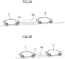
Figure 2] Figure 2A, 2B are schematic diagrams showing deceleration and stop of the vehicle on an uphill road. - [
Figure 3] Figure 3 is a time chart showing driving control according to an embodiment of the present invention. - [
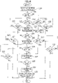
Figure 4] Figure 4 is a flowchart showing the driving control according to the embodiment of the present invention. - [
Figure 5] Figure 5 is a flowchart showing control when a brake pedal is operated in the driving control according to the embodiment of the present invention. - Hereinafter, an embodiment of the present invention will be described in detail with reference to the drawings.
- In
Figure 1 , a vehicle 1 includes aninternal combustion engine 2 and an AMT type automatic transmission 5 in a torque transmission path from theengine 2 to drive wheels (3), and also includes anengine controller 10 as engine control means for making a torque request to theengine 2, and anAMT controller 14 that controls a gear shifting operation of the automatic transmission 5 to a gear stage determined based on an engine speed and the torque request, and a clutch opening/closing operation linked thereto. - The vehicle 1 includes a brake system that includes a brake control apparatus 20 (including a brake controller and a brake actuator (hydraulic actuator)) capable of individually controlling the braking force of
brakes 33 of left and rightfront wheels 3 andbrakes 44 of left and rightrear wheels 4, abrake pedal 21, ahydraulic pressure sensor 22,wheel speed sensors 23 of the left and rightfront wheels 3 andwheel speed sensors 24 of the left and rightrear wheels 4, and forms an ABS/vehicle behavior stabilization apparatus. - The vehicle 1 further includes vehicle ahead detection means 11 that forms an ACC system together with an
ACC controller 12. One or more detection means, such as a millimeter wave radar, stereo camera, or LiDAR, that have a function for detecting the presence of a vehicle ahead or an object (obstacle or structure) in front of the vehicle and can measure a relative distance between the vehicle ahead or obstacle and the vehicle can be used for the vehicle ahead detection means 11. - The
ACC controller 12 is configured to issue an acceleration/deceleration command to theengine controller 10 and thebrake control apparatus 20 instead of the driver's accelerator/brake operation on the basis of a vehicle speed calculated from detection information of the vehicle ahead detection means 11 and detection values of thewheel speed sensors - That is, the brake control apparatus 20 (brake controller) that has received the deceleration command from the
ACC controller 12 controls the vehicle speed by issuing a braking request (hydraulic request) to a brake actuator and controlling the braking force of thebrakes engine controller 10 that has received the acceleration/deceleration command as a torque request to theengine 2 from theACC controller 12, controls actuator output (degree of throttle opening), thereby controls the torque of theengine 2, and controls the vehicle speed. - By the above-described control of the
ACC controller 12, the vehicle 1 performs constant speed cruise while maintaining a set vehicle speed when there is no vehicle ahead, and when catching up with a vehicle ahead, performs following cruise to the vehicle ahead while maintaining an inter-vehicle distance corresponding to a predetermined inter-vehicle time (time gap = inter-vehicle distance / vehicle speed) according to the speed of the vehicle ahead. Furthermore, when the vehicle ahead decelerates and stops while the vehicle 1 is performing following cruise or the vehicle 1 approaches the vehicle ahead that has decelerated and stopped, the vehicle 1 decelerates and stops while ensuring the predetermined inter-vehicle distance, and when the vehicle ahead starts within a predetermined time, restarts accordingly and continues the following cruise. - The
engine controller 10,AMT controller 14, brake controller of thebrake control apparatus 20, andACC controller 12 described above each include a microcomputer (MCU) composed of a ROM for storing a control program, setting data or the like, a RAM for temporarily storing arithmetic processing results, a CPU for performing arithmetic processing, a communication interface (I/F), and the like, and are connected with each other intercommunicatively together with the vehicle ahead detection means 11 and a sensor group including agradient sensor 13 described below via an on-vehicle network (such as a CAN). - The vehicle 1 according to the embodiment of the present invention includes a
gradient sensor 13 as gradient detection means for detecting a road surface gradient. As thegradient sensor 13, a gradient sensor for detecting a gradient in the front-rear direction of the vehicle 1 on the basis of gravitational acceleration, an acceleration sensor, a multi-axis inertia sensor, or the like can be used. - The driving control system according to the present invention is characterized by deceleration stop control in an ACC function performed by the
ACC controller 12, and performs deceleration stop control in consideration of the road surface gradient detected by thegradient sensor 13 in addition to the detection information of the vehicle ahead detection means 11. Hereinafter, improved deceleration stop control will be described with reference toFigures 2-4 . - First, as shown in
Figure 2A , when the vehicle ahead 6 decelerates and stops while the vehicle is performing following cruise at a predetermined set inter-vehicle time Xg to a vehicle ahead 6 detected by the vehicle ahead detection means 11, or the vehicle approaches the vehicle ahead 6 that decelerates and stops, theACC controller 12 issues a deceleration command. - As shown in
Figure 3 , a brake hydraulic pressure rises due to a braking request and a braking force starts to act; on the other hand, at the same time as a torque request to theengine 2 becomes zero, a clutch of the automatic transmission 5 is disengaged, a drive torque transmitted to a drive shaft becomes zero, and the vehicle 1 starts decelerating at a predetermined deceleration according to the braking request (Figure 4 , step 100). - After that, as shown in
Figure 2B , in a case of a sloped road about which a road surface gradient equal to or greater than a predetermined threshold value (for example, 3%) is detected by the gradient sensor 13 (YES instep 101 inFigure 4 ) immediately before the vehicle 1 stops while ensuring an inter-vehicle distance Xd from the vehicle ahead 6, a required value of creep torque (torque that makes the vehicle 1 stand still against the road surface gradient) that compensates for the road surface gradient is calculated. - Next, a torque request is issued to the
engine 2 on the basis of the required value (Figure 4 , step 103) when the vehicle 1 reaches a first vehicle speed Va (for example, 3 km/h) immediately before stopping (point a inFigure 3 and YES instep 102 inFigure 4 ), and at the same time, a fastening force is applied to the clutch of the automatic transmission 5, and the torque begins to be transmitted to the drive shaft. - Although the torque transmission starts together with such a torque request and clutch fastening, the braking force of the brakes further decelerates the vehicle 1, and when a second vehicle speed Vb (for example, 2 km/h) is reached (point b in
Figure 3 and YES instep 104 inFigure 4 ), a brake pressure is temporarily reduced (point b inFigure 3 andstep 105 inFigure 4 ). - By the increase in the drive torque and the reduction in the brake pressure, the deceleration of the vehicle 1 is mitigated; when the vehicle 1 reaches a third speed Vc (for example, 1 km/h) regarded as substantially a stopped state (point c in
Figure 3 and YES instep 106 inFigure 4 ), the brake pressure is increased (step 107 inFigure 4 ); and even after the vehicle 1 completely stops (YES in step 108) and the increase in the brake pressure is completed, the brake pressure is maintained (step 109). In the elapse of a predetermined time after stopping, the torque request becomes zero, and at the same time, the clutch of the automatic transmission 5 is disengaged (step 110 inFigure 4 ). - On the other hand, in a case of a flat road for which the road surface gradient detected by the
gradient sensor 13 is less than the predetermined threshold value (for example, 3%) (NO instep 101 inFigure 4 ) immediately before the vehicle 1 stops while ensuring the predetermined inter-vehicle distance Xd from the vehicle ahead 6, the brake pressure is temporarily reduced (step 112 inFigure 4 ) when the predetermined vehicle speed Vd (for example, 1.5 km/h) is reached (YES instep 111 inFigure 4 ); then when the vehicle 1 reaches the third speed Vc (for example, 0.5 km/h) regarded as substantially a stopped state (YES instep 113 inFigure 4 ), the brake pressure is increased (step 107 inFigure 4 ), and the vehicle 1 is completely stopped (steps 108-109). - In
Figure 4 , in eachstep step 101 or in eachstep ACC controller 12 is stopped due to start of the vehicle ahead 6 or the like, the deceleration stop control ends at that time point, and the operation returns to ACC control. When the vehicle ahead 6 starts after deceleration stop, depression of the accelerator pedal or a predetermined button operation makes the operation return to the ACC control. - After the torque request according to the road surface gradient is issued in
step 103 inFigure 4 and the clutch of the automatic transmission 5 is fastened (for example, point b' inFigure 3 ), as shown inFigure 5 , when thebrake pedal 21 is depressed by the driver, and a brake pedal ON signal is detected (step 131), the torque request immediately becomes zero in order to avoid engine stall, and at the same time, the clutch of the automatic transmission 5 is disengaged (step 110). - In this case, it is determined that control by the
ACC controller 12 is overridden by the driver's brake pedal operation, and the driver may be notified of ACC cancellation by an HMI apparatus and the shift to manual operation may be performed or the ACC control may be continued by the specified button operation or accelerator pedal operation, as described above. - As detailed above, in the driving control system according to the present invention, since the predetermined torque request is made in parallel with the control of increasing pressure after temporarily reducing pressure of the braking force when a road surface gradient equal to or greater than the predetermined threshold value is detected when the vehicle 1 reaches the first vehicle speed Va based on which the vehicle 1 is determined to be immediately before stopping, the vehicle 1 can stop in a state in which torque is applied in the uphill direction while suppressing pitching at the time of decelerating and stopping, and the same deceleration-and-stop sensation as on a flat road can be provided without sensation of a slight backward movement, even on an uphill road.
- In particular, by starting the control of increasing pressure after temporarily reducing pressure of the braking force at a second time point when the vehicle reaches the second vehicle speed Vb that is slower than the first vehicle speed Va after the predetermined torque request at a first time point when the vehicle reaches the first vehicle speed Va based on which the vehicle is determined to be immediately before stopping, the vehicle can be stopped in a state in which the torque is reliably applied before the temporary reduction in the braking force.
- Although the vehicle 1 equipped with the AMT type automatic transmission 5 performs fastening processing of the clutch at the same time as the torque request, a fastening force is applied to the clutch immediately before the braking force is increased and a time to generate a driving force (creep torque) is very short, and so the load on the clutch is small and there is no effect on the clutch due to heat generation.
- A torque request when a road surface gradient equal to or greater than the predetermined threshold value is detected is preferably a torque request corresponding to a torque for making the vehicle stand still against the road surface gradient. However, it is not necessary to be a request value to strictly balance, a compensation torque request value is set according to the road surface gradient within a range in which the torque request is not excessive. For example, the compensation torque is set to be greater in proportion to the road surface gradient, and it is advantageous to prepare a compensation torque request value corresponding to the road surface gradient as a lookup table.
- It is also possible to obtain acceleration of the vehicle 1 and slip ratios of the wheels from wheel speeds detected by the
wheel speed sensors - In the above embodiment, in the vehicle 1 equipped with the AMT type automatic transmission 5 in the torque transmission path from the
engine 2 to the drive wheels (3), the clutch of the automatic transmission 5 is disengaged at the same time as the torque request becomes zero, and the clutch is fastened at the same time as the torque request. However, the present invention can also be implemented in a vehicle equipped with another type of automatic transmission, such as a CTV type, which is weaker than a force to balance the gradient. - Furthermore, the embodiment describes the case in which the present invention is implemented in the vehicle 1 having the ACC function. However, the present invention can also be implemented in a vehicle having an automated lane keeping function (automated driving function) including the ACC function.
- Although embodiments of the present invention have been described above, the present invention is not limited to these embodiments, and various modifications and changes are possible based on the technical concept of the present invention.
-
- 1
- Vehicle
- 2
- Engine
- 5
- Automatic transmission
- 10
- Engine controller
- 11
- Vehicle ahead detection means
- 12
- ACC controller
- 13
- Gradient sensor
- 14
- AMT controller
- 20
- Brake control apparatus
- 21
- Brake pedal
- 22
- Hydraulic pressure sensor
- 23, 24
- Wheel speed sensor
- 33, 44
- Brake
Claims (9)
- A driving control apparatus for a vehicle comprising: engine control means for controlling an engine according to a torque request, brake control means for controlling a braking force of a break according to a braking request, gradient detection means for detecting a road surface gradient, and vehicle ahead detection means for detecting a vehicle ahead,the driving control apparatus having a function for decelerating and stopping with maintaining a predetermined inter-vehicle distance when the vehicle ahead detected by the vehicle ahead detection means decelerates to a stop, and configured to perform pitching suppression control of increasing pressure after temporarily reducing pressure of the braking force immediately before the vehicle stops,wherein the driving control apparatus is further configured to make a predetermined torque request in parallel with the pitching suppression control in a case in which a road surface gradient equal to or greater than a predetermined threshold value is detected by the gradient detection means when the vehicle reaches a first vehicle speed based on which the vehicle is determined to be immediately before stopping.
- The driving control apparatus for the vehicle according to claim 1, wherein the torque request is set to zero and a predetermined braking request is made in order to decelerate and stop the vehicle when the vehicle ahead decelerates and stops, the predetermined torque request is made in a case in which a road surface gradient equal to or greater than the predetermined value is detected by the gradient detection means at a first time point when the vehicle reaches the first vehicle speed based on which the vehicle is determined to be immediately before stopping, and at the same time or a second time point when the vehicle reaches a second vehicle speed that is slower than the first vehicle speed, the pitching suppression control of increasing pressure after temporarily reducing pressure of the braking force is started.
- The driving control apparatus for the vehicle according to claim 1 or 2, wherein the torque request in the case in which the road surface gradient equal to or greater than the predetermined threshold value is detected is corresponding to a torque for making the vehicle stand still against the road surface gradient.
- The driving control apparatus for the vehicle according to any one of claims 1 to 3, wherein the torque request in the case in which the road surface gradient equal to or greater than the predetermined threshold value is detected is set to zero at elapse of a predetermined time after the vehicle stops.
- The driving control apparatus for the vehicle according to any one of claims 1 to 4, wherein the torque request is set to zero when a brake pedal is operated after the torque request in the case in which the road surface gradient equal to or greater than the predetermined threshold value is detected.
- The driving control apparatus for the vehicle according to claim 2 or 3, wherein:an AMT type automatic transmission is provided in a torque transmission path from the engine to drive wheels; anda clutch of the automatic transmission is disengaged at the same time as the torque request is set to zero when the vehicle ahead decelerated to a stop, and the clutch is engaged at the same time as the predetermined torque request in the case in which the road surface gradient equal to or greater than the predetermined threshold value is detected by the gradient detection means at the first time point.
- The driving control apparatus for the vehicle according to claim 6, wherein the torque request in the case in which the road surface gradient equal to or greater than the predetermined threshold value is detected is set to zero at elapse of a predetermined time after the vehicle stops, and at the same time the clutch is disengaged.
- The driving control apparatus for the vehicle according to claim 6 or 7, wherein the torque request is set to zero when a brake pedal is operated after the torque request in the case in which the road surface gradient equal to or greater than the predetermined threshold value is detected, and at the same time, the clutch is disengaged.
- The driving control apparatus for the vehicle according to any one of claims 1 to 8, wherein the torque request is kept at zero when a detection value of the gradient detection means is less than the predetermined threshold value when the vehicle reaches the first vehicle speed based on which the vehicle is determined to be immediately before stopping.
Applications Claiming Priority (1)
| Application Number | Priority Date | Filing Date | Title |
|---|---|---|---|
| JP2021037377A JP7627427B2 (en) | 2021-03-09 | 2021-03-09 | Vehicle driving control device |
Publications (2)
| Publication Number | Publication Date |
|---|---|
| EP4056437A1 true EP4056437A1 (en) | 2022-09-14 |
| EP4056437B1 EP4056437B1 (en) | 2024-09-25 |
Family
ID=78825156
Family Applications (1)
| Application Number | Title | Priority Date | Filing Date |
|---|---|---|---|
| EP21212906.8A Active EP4056437B1 (en) | 2021-03-09 | 2021-12-07 | Driving control apparatus for vehicle |
Country Status (3)
| Country | Link |
|---|---|
| EP (1) | EP4056437B1 (en) |
| JP (1) | JP7627427B2 (en) |
| HU (1) | HUE069654T2 (en) |
Cited By (2)
| Publication number | Priority date | Publication date | Assignee | Title |
|---|---|---|---|---|
| WO2024239799A1 (en) * | 2023-05-23 | 2024-11-28 | 蔚来汽车科技(安徽)有限公司 | Vehicle braking-to-stop control method, computer device, storage medium, and vehicle |
| US20250002017A1 (en) * | 2023-06-28 | 2025-01-02 | Honda Motor Co., Ltd. | Vehicle control device and control method |
Families Citing this family (3)
| Publication number | Priority date | Publication date | Assignee | Title |
|---|---|---|---|---|
| EP4610128A1 (en) * | 2022-10-24 | 2025-09-03 | SoftBank Group Corp. | Information processing device, vehicle, information processing method, and program |
| EP4610134A1 (en) * | 2022-10-24 | 2025-09-03 | SoftBank Group Corp. | Information processing device, vehicle, and program |
| JP7842385B2 (en) * | 2023-03-27 | 2026-04-08 | 三菱自動車工業株式会社 | Vehicle body attitude control system |
Citations (6)
| Publication number | Priority date | Publication date | Assignee | Title |
|---|---|---|---|---|
| US20110276216A1 (en) * | 2010-05-07 | 2011-11-10 | Texas Instruments Incorporated | Automotive cruise controls, circuits, systems and processes |
| US20110307154A1 (en) * | 2010-06-10 | 2011-12-15 | Denso Corporation | Braking/driving control apparatus for vehicle |
| GB2516934A (en) * | 2013-08-07 | 2015-02-11 | Jaguar Land Rover Ltd | Vehicle speed control system and method |
| GB2519024A (en) * | 2012-08-16 | 2015-04-08 | Jaguar Land Rover Ltd | Improvements in vehicle speed control |
| JP2016028913A (en) * | 2014-07-25 | 2016-03-03 | 日産自動車株式会社 | Vehicle longitudinal vibration control device |
| US20170043767A1 (en) * | 2015-08-13 | 2017-02-16 | Ford Global Technologies, Llc | Vehicle having acc stop and go with braking auto-hold to increase engine autostop availability |
Family Cites Families (2)
| Publication number | Priority date | Publication date | Assignee | Title |
|---|---|---|---|---|
| JP5613597B2 (en) | 2011-03-16 | 2014-10-29 | 富士重工業株式会社 | Vehicle driving support device |
| JP7147585B2 (en) | 2019-01-23 | 2022-10-05 | トヨタ自動車株式会社 | vehicle controller |
-
2021
- 2021-03-09 JP JP2021037377A patent/JP7627427B2/en active Active
- 2021-12-07 HU HUE21212906A patent/HUE069654T2/en unknown
- 2021-12-07 EP EP21212906.8A patent/EP4056437B1/en active Active
Patent Citations (6)
| Publication number | Priority date | Publication date | Assignee | Title |
|---|---|---|---|---|
| US20110276216A1 (en) * | 2010-05-07 | 2011-11-10 | Texas Instruments Incorporated | Automotive cruise controls, circuits, systems and processes |
| US20110307154A1 (en) * | 2010-06-10 | 2011-12-15 | Denso Corporation | Braking/driving control apparatus for vehicle |
| GB2519024A (en) * | 2012-08-16 | 2015-04-08 | Jaguar Land Rover Ltd | Improvements in vehicle speed control |
| GB2516934A (en) * | 2013-08-07 | 2015-02-11 | Jaguar Land Rover Ltd | Vehicle speed control system and method |
| JP2016028913A (en) * | 2014-07-25 | 2016-03-03 | 日産自動車株式会社 | Vehicle longitudinal vibration control device |
| US20170043767A1 (en) * | 2015-08-13 | 2017-02-16 | Ford Global Technologies, Llc | Vehicle having acc stop and go with braking auto-hold to increase engine autostop availability |
Cited By (2)
| Publication number | Priority date | Publication date | Assignee | Title |
|---|---|---|---|---|
| WO2024239799A1 (en) * | 2023-05-23 | 2024-11-28 | 蔚来汽车科技(安徽)有限公司 | Vehicle braking-to-stop control method, computer device, storage medium, and vehicle |
| US20250002017A1 (en) * | 2023-06-28 | 2025-01-02 | Honda Motor Co., Ltd. | Vehicle control device and control method |
Also Published As
| Publication number | Publication date |
|---|---|
| HUE069654T2 (en) | 2025-03-28 |
| JP2022137732A (en) | 2022-09-22 |
| JP7627427B2 (en) | 2025-02-06 |
| EP4056437B1 (en) | 2024-09-25 |
Similar Documents
| Publication | Publication Date | Title |
|---|---|---|
| EP4056437B1 (en) | Driving control apparatus for vehicle | |
| US10625741B2 (en) | Vehicle control device | |
| US9180769B2 (en) | Vehicle control system | |
| US6339740B1 (en) | Adaptive vehicle speed control system | |
| US8214124B2 (en) | Cruise control system and method | |
| US8292784B2 (en) | Vehicle control device | |
| US20110022284A1 (en) | Acceleration control device | |
| US8996275B2 (en) | Control device for vehicle | |
| JPH10109627A (en) | Automatic deceleration control method, automatic deceleration control device, inter-vehicle distance control method, inter-vehicle distance control device, and storage medium | |
| EP2000380A2 (en) | Vehicle travel control device and vehicle travel control method | |
| CN110271520B (en) | vehicle control device | |
| JP2017154614A (en) | Vehicle travel controlling apparatus | |
| JP2024051012A (en) | Vehicle Driving Assistance Device | |
| JP2020059367A (en) | Control device of vehicle | |
| US6772059B2 (en) | Method for adaptive distance and/or driving speed adjustment in a motor vehicle | |
| CN115009277A (en) | Downhill control method and system for automobile adaptive cruise system | |
| JP2010241245A (en) | Vehicle driving force control device | |
| US11752877B2 (en) | Control device of vehicle | |
| JP7294185B2 (en) | Driving support method and driving support device | |
| EP3441274A1 (en) | Traveling control device, vehicle, and traveling control method | |
| JP7716647B2 (en) | Hybrid vehicle driving control device | |
| JP4649279B2 (en) | Brake control device for vehicle | |
| JP2014172456A (en) | Controller of idling stop car | |
| JP7622453B2 (en) | Driving Support Devices | |
| JP2025129762A (en) | Vehicle driving control system |
Legal Events
| Date | Code | Title | Description |
|---|---|---|---|
| PUAI | Public reference made under article 153(3) epc to a published international application that has entered the european phase |
Free format text: ORIGINAL CODE: 0009012 |
|
| STAA | Information on the status of an ep patent application or granted ep patent |
Free format text: STATUS: REQUEST FOR EXAMINATION WAS MADE |
|
| 17P | Request for examination filed |
Effective date: 20211207 |
|
| AK | Designated contracting states |
Kind code of ref document: A1 Designated state(s): AL AT BE BG CH CY CZ DE DK EE ES FI FR GB GR HR HU IE IS IT LI LT LU LV MC MK MT NL NO PL PT RO RS SE SI SK SM TR |
|
| GRAP | Despatch of communication of intention to grant a patent |
Free format text: ORIGINAL CODE: EPIDOSNIGR1 |
|
| STAA | Information on the status of an ep patent application or granted ep patent |
Free format text: STATUS: GRANT OF PATENT IS INTENDED |
|
| INTG | Intention to grant announced |
Effective date: 20240612 |
|
| GRAS | Grant fee paid |
Free format text: ORIGINAL CODE: EPIDOSNIGR3 |
|
| GRAA | (expected) grant |
Free format text: ORIGINAL CODE: 0009210 |
|
| STAA | Information on the status of an ep patent application or granted ep patent |
Free format text: STATUS: THE PATENT HAS BEEN GRANTED |
|
| AK | Designated contracting states |
Kind code of ref document: B1 Designated state(s): AL AT BE BG CH CY CZ DE DK EE ES FI FR GB GR HR HU IE IS IT LI LT LU LV MC MK MT NL NO PL PT RO RS SE SI SK SM TR |
|
| REG | Reference to a national code |
Ref country code: GB Ref legal event code: FG4D |
|
| REG | Reference to a national code |
Ref country code: CH Ref legal event code: EP |
|
| REG | Reference to a national code |
Ref country code: DE Ref legal event code: R096 Ref document number: 602021019253 Country of ref document: DE |
|
| REG | Reference to a national code |
Ref country code: IE Ref legal event code: FG4D |
|
| REG | Reference to a national code |
Ref country code: LT Ref legal event code: MG9D |
|
| PG25 | Lapsed in a contracting state [announced via postgrant information from national office to epo] |
Ref country code: NO Free format text: LAPSE BECAUSE OF FAILURE TO SUBMIT A TRANSLATION OF THE DESCRIPTION OR TO PAY THE FEE WITHIN THE PRESCRIBED TIME-LIMIT Effective date: 20241225 |
|
| PG25 | Lapsed in a contracting state [announced via postgrant information from national office to epo] |
Ref country code: GR Free format text: LAPSE BECAUSE OF FAILURE TO SUBMIT A TRANSLATION OF THE DESCRIPTION OR TO PAY THE FEE WITHIN THE PRESCRIBED TIME-LIMIT Effective date: 20241226 Ref country code: FI Free format text: LAPSE BECAUSE OF FAILURE TO SUBMIT A TRANSLATION OF THE DESCRIPTION OR TO PAY THE FEE WITHIN THE PRESCRIBED TIME-LIMIT Effective date: 20240925 |
|
| PG25 | Lapsed in a contracting state [announced via postgrant information from national office to epo] |
Ref country code: BG Free format text: LAPSE BECAUSE OF FAILURE TO SUBMIT A TRANSLATION OF THE DESCRIPTION OR TO PAY THE FEE WITHIN THE PRESCRIBED TIME-LIMIT Effective date: 20240925 |
|
| PG25 | Lapsed in a contracting state [announced via postgrant information from national office to epo] |
Ref country code: LV Free format text: LAPSE BECAUSE OF FAILURE TO SUBMIT A TRANSLATION OF THE DESCRIPTION OR TO PAY THE FEE WITHIN THE PRESCRIBED TIME-LIMIT Effective date: 20240925 |
|
| PG25 | Lapsed in a contracting state [announced via postgrant information from national office to epo] |
Ref country code: RS Free format text: LAPSE BECAUSE OF FAILURE TO SUBMIT A TRANSLATION OF THE DESCRIPTION OR TO PAY THE FEE WITHIN THE PRESCRIBED TIME-LIMIT Effective date: 20241225 |
|
| REG | Reference to a national code |
Ref country code: NL Ref legal event code: MP Effective date: 20240925 |
|
| PG25 | Lapsed in a contracting state [announced via postgrant information from national office to epo] |
Ref country code: RS Free format text: LAPSE BECAUSE OF FAILURE TO SUBMIT A TRANSLATION OF THE DESCRIPTION OR TO PAY THE FEE WITHIN THE PRESCRIBED TIME-LIMIT Effective date: 20241225 Ref country code: NO Free format text: LAPSE BECAUSE OF FAILURE TO SUBMIT A TRANSLATION OF THE DESCRIPTION OR TO PAY THE FEE WITHIN THE PRESCRIBED TIME-LIMIT Effective date: 20241225 Ref country code: LV Free format text: LAPSE BECAUSE OF FAILURE TO SUBMIT A TRANSLATION OF THE DESCRIPTION OR TO PAY THE FEE WITHIN THE PRESCRIBED TIME-LIMIT Effective date: 20240925 Ref country code: GR Free format text: LAPSE BECAUSE OF FAILURE TO SUBMIT A TRANSLATION OF THE DESCRIPTION OR TO PAY THE FEE WITHIN THE PRESCRIBED TIME-LIMIT Effective date: 20241226 Ref country code: FI Free format text: LAPSE BECAUSE OF FAILURE TO SUBMIT A TRANSLATION OF THE DESCRIPTION OR TO PAY THE FEE WITHIN THE PRESCRIBED TIME-LIMIT Effective date: 20240925 Ref country code: BG Free format text: LAPSE BECAUSE OF FAILURE TO SUBMIT A TRANSLATION OF THE DESCRIPTION OR TO PAY THE FEE WITHIN THE PRESCRIBED TIME-LIMIT Effective date: 20240925 |
|
| REG | Reference to a national code |
Ref country code: AT Ref legal event code: MK05 Ref document number: 1726440 Country of ref document: AT Kind code of ref document: T Effective date: 20240925 |
|
| PG25 | Lapsed in a contracting state [announced via postgrant information from national office to epo] |
Ref country code: NL Free format text: LAPSE BECAUSE OF FAILURE TO SUBMIT A TRANSLATION OF THE DESCRIPTION OR TO PAY THE FEE WITHIN THE PRESCRIBED TIME-LIMIT Effective date: 20240925 |
|
| REG | Reference to a national code |
Ref country code: HU Ref legal event code: AG4A Ref document number: E069654 Country of ref document: HU |
|
| PG25 | Lapsed in a contracting state [announced via postgrant information from national office to epo] |
Ref country code: IS Free format text: LAPSE BECAUSE OF FAILURE TO SUBMIT A TRANSLATION OF THE DESCRIPTION OR TO PAY THE FEE WITHIN THE PRESCRIBED TIME-LIMIT Effective date: 20250125 Ref country code: PT Free format text: LAPSE BECAUSE OF FAILURE TO SUBMIT A TRANSLATION OF THE DESCRIPTION OR TO PAY THE FEE WITHIN THE PRESCRIBED TIME-LIMIT Effective date: 20250127 |
|
| PG25 | Lapsed in a contracting state [announced via postgrant information from national office to epo] |
Ref country code: RO Free format text: LAPSE BECAUSE OF FAILURE TO SUBMIT A TRANSLATION OF THE DESCRIPTION OR TO PAY THE FEE WITHIN THE PRESCRIBED TIME-LIMIT Effective date: 20240925 Ref country code: SM Free format text: LAPSE BECAUSE OF FAILURE TO SUBMIT A TRANSLATION OF THE DESCRIPTION OR TO PAY THE FEE WITHIN THE PRESCRIBED TIME-LIMIT Effective date: 20240925 |
|
| PG25 | Lapsed in a contracting state [announced via postgrant information from national office to epo] |
Ref country code: ES Free format text: LAPSE BECAUSE OF FAILURE TO SUBMIT A TRANSLATION OF THE DESCRIPTION OR TO PAY THE FEE WITHIN THE PRESCRIBED TIME-LIMIT Effective date: 20240925 |
|
| PG25 | Lapsed in a contracting state [announced via postgrant information from national office to epo] |
Ref country code: EE Free format text: LAPSE BECAUSE OF FAILURE TO SUBMIT A TRANSLATION OF THE DESCRIPTION OR TO PAY THE FEE WITHIN THE PRESCRIBED TIME-LIMIT Effective date: 20240925 Ref country code: AT Free format text: LAPSE BECAUSE OF FAILURE TO SUBMIT A TRANSLATION OF THE DESCRIPTION OR TO PAY THE FEE WITHIN THE PRESCRIBED TIME-LIMIT Effective date: 20240925 |
|
| PG25 | Lapsed in a contracting state [announced via postgrant information from national office to epo] |
Ref country code: PL Free format text: LAPSE BECAUSE OF FAILURE TO SUBMIT A TRANSLATION OF THE DESCRIPTION OR TO PAY THE FEE WITHIN THE PRESCRIBED TIME-LIMIT Effective date: 20240925 Ref country code: CZ Free format text: LAPSE BECAUSE OF FAILURE TO SUBMIT A TRANSLATION OF THE DESCRIPTION OR TO PAY THE FEE WITHIN THE PRESCRIBED TIME-LIMIT Effective date: 20240925 |
|
| PG25 | Lapsed in a contracting state [announced via postgrant information from national office to epo] |
Ref country code: IT Free format text: LAPSE BECAUSE OF FAILURE TO SUBMIT A TRANSLATION OF THE DESCRIPTION OR TO PAY THE FEE WITHIN THE PRESCRIBED TIME-LIMIT Effective date: 20240925 Ref country code: SK Free format text: LAPSE BECAUSE OF FAILURE TO SUBMIT A TRANSLATION OF THE DESCRIPTION OR TO PAY THE FEE WITHIN THE PRESCRIBED TIME-LIMIT Effective date: 20240925 |
|
| REG | Reference to a national code |
Ref country code: DE Ref legal event code: R097 Ref document number: 602021019253 Country of ref document: DE |
|
| PG25 | Lapsed in a contracting state [announced via postgrant information from national office to epo] |
Ref country code: MC Free format text: LAPSE BECAUSE OF FAILURE TO SUBMIT A TRANSLATION OF THE DESCRIPTION OR TO PAY THE FEE WITHIN THE PRESCRIBED TIME-LIMIT Effective date: 20240925 |
|
| PG25 | Lapsed in a contracting state [announced via postgrant information from national office to epo] |
Ref country code: DK Free format text: LAPSE BECAUSE OF FAILURE TO SUBMIT A TRANSLATION OF THE DESCRIPTION OR TO PAY THE FEE WITHIN THE PRESCRIBED TIME-LIMIT Effective date: 20240925 |
|
| REG | Reference to a national code |
Ref country code: CH Ref legal event code: PL |
|
| PLBE | No opposition filed within time limit |
Free format text: ORIGINAL CODE: 0009261 |
|
| STAA | Information on the status of an ep patent application or granted ep patent |
Free format text: STATUS: NO OPPOSITION FILED WITHIN TIME LIMIT |
|
| PG25 | Lapsed in a contracting state [announced via postgrant information from national office to epo] |
Ref country code: LU Free format text: LAPSE BECAUSE OF NON-PAYMENT OF DUE FEES Effective date: 20241207 |
|
| 26N | No opposition filed |
Effective date: 20250626 |
|
| PG25 | Lapsed in a contracting state [announced via postgrant information from national office to epo] |
Ref country code: SE Free format text: LAPSE BECAUSE OF FAILURE TO SUBMIT A TRANSLATION OF THE DESCRIPTION OR TO PAY THE FEE WITHIN THE PRESCRIBED TIME-LIMIT Effective date: 20240925 |
|
| REG | Reference to a national code |
Ref country code: BE Ref legal event code: MM Effective date: 20241231 |
|
| PG25 | Lapsed in a contracting state [announced via postgrant information from national office to epo] |
Ref country code: BE Free format text: LAPSE BECAUSE OF NON-PAYMENT OF DUE FEES Effective date: 20241231 |
|
| PG25 | Lapsed in a contracting state [announced via postgrant information from national office to epo] |
Ref country code: CH Free format text: LAPSE BECAUSE OF NON-PAYMENT OF DUE FEES Effective date: 20241231 |
|
| PG25 | Lapsed in a contracting state [announced via postgrant information from national office to epo] |
Ref country code: IE Free format text: LAPSE BECAUSE OF NON-PAYMENT OF DUE FEES Effective date: 20241207 |
|
| PGFP | Annual fee paid to national office [announced via postgrant information from national office to epo] |
Ref country code: DE Payment date: 20251028 Year of fee payment: 5 |
|
| PG25 | Lapsed in a contracting state [announced via postgrant information from national office to epo] |
Ref country code: HR Free format text: LAPSE BECAUSE OF FAILURE TO SUBMIT A TRANSLATION OF THE DESCRIPTION OR TO PAY THE FEE WITHIN THE PRESCRIBED TIME-LIMIT Effective date: 20240925 |
|
| PGFP | Annual fee paid to national office [announced via postgrant information from national office to epo] |
Ref country code: HU Payment date: 20251127 Year of fee payment: 5 Ref country code: FR Payment date: 20251110 Year of fee payment: 5 |
|
| PG25 | Lapsed in a contracting state [announced via postgrant information from national office to epo] |
Ref country code: CY Free format text: LAPSE BECAUSE OF FAILURE TO SUBMIT A TRANSLATION OF THE DESCRIPTION OR TO PAY THE FEE WITHIN THE PRESCRIBED TIME-LIMIT; INVALID AB INITIO Effective date: 20211207 |