EP4056210A1 - Pumping mechanism with wire-pulled plunger - Google Patents
Pumping mechanism with wire-pulled plunger Download PDFInfo
- Publication number
- EP4056210A1 EP4056210A1 EP22161247.6A EP22161247A EP4056210A1 EP 4056210 A1 EP4056210 A1 EP 4056210A1 EP 22161247 A EP22161247 A EP 22161247A EP 4056210 A1 EP4056210 A1 EP 4056210A1
- Authority
- EP
- European Patent Office
- Prior art keywords
- reservoir
- plunger
- wire
- user
- flexible member
- Prior art date
- Legal status (The legal status is an assumption and is not a legal conclusion. Google has not performed a legal analysis and makes no representation as to the accuracy of the status listed.)
- Pending
Links
Images




Classifications
-
- A—HUMAN NECESSITIES
- A61—MEDICAL OR VETERINARY SCIENCE; HYGIENE
- A61M—DEVICES FOR INTRODUCING MEDIA INTO, OR ONTO, THE BODY; DEVICES FOR TRANSDUCING BODY MEDIA OR FOR TAKING MEDIA FROM THE BODY; DEVICES FOR PRODUCING OR ENDING SLEEP OR STUPOR
- A61M5/00—Devices for bringing media into the body in a subcutaneous, intra-vascular or intramuscular way; Accessories therefor, e.g. filling or cleaning devices, arm-rests
- A61M5/14—Infusion devices, e.g. infusing by gravity; Blood infusion; Accessories therefor
- A61M5/142—Pressure infusion, e.g. using pumps
- A61M5/14212—Pumping with an aspiration and an expulsion action
- A61M5/14232—Roller pumps
-
- A—HUMAN NECESSITIES
- A61—MEDICAL OR VETERINARY SCIENCE; HYGIENE
- A61M—DEVICES FOR INTRODUCING MEDIA INTO, OR ONTO, THE BODY; DEVICES FOR TRANSDUCING BODY MEDIA OR FOR TAKING MEDIA FROM THE BODY; DEVICES FOR PRODUCING OR ENDING SLEEP OR STUPOR
- A61M5/00—Devices for bringing media into the body in a subcutaneous, intra-vascular or intramuscular way; Accessories therefor, e.g. filling or cleaning devices, arm-rests
- A61M5/14—Infusion devices, e.g. infusing by gravity; Blood infusion; Accessories therefor
- A61M5/142—Pressure infusion, e.g. using pumps
- A61M5/14244—Pressure infusion, e.g. using pumps adapted to be carried by the patient, e.g. portable on the body
- A61M5/14248—Pressure infusion, e.g. using pumps adapted to be carried by the patient, e.g. portable on the body of the skin patch type
-
- A—HUMAN NECESSITIES
- A61—MEDICAL OR VETERINARY SCIENCE; HYGIENE
- A61M—DEVICES FOR INTRODUCING MEDIA INTO, OR ONTO, THE BODY; DEVICES FOR TRANSDUCING BODY MEDIA OR FOR TAKING MEDIA FROM THE BODY; DEVICES FOR PRODUCING OR ENDING SLEEP OR STUPOR
- A61M5/00—Devices for bringing media into the body in a subcutaneous, intra-vascular or intramuscular way; Accessories therefor, e.g. filling or cleaning devices, arm-rests
- A61M5/14—Infusion devices, e.g. infusing by gravity; Blood infusion; Accessories therefor
- A61M5/142—Pressure infusion, e.g. using pumps
- A61M5/145—Pressure infusion, e.g. using pumps using pressurised reservoirs, e.g. pressurised by means of pistons
- A61M5/1452—Pressure infusion, e.g. using pumps using pressurised reservoirs, e.g. pressurised by means of pistons pressurised by means of pistons
-
- A—HUMAN NECESSITIES
- A61—MEDICAL OR VETERINARY SCIENCE; HYGIENE
- A61M—DEVICES FOR INTRODUCING MEDIA INTO, OR ONTO, THE BODY; DEVICES FOR TRANSDUCING BODY MEDIA OR FOR TAKING MEDIA FROM THE BODY; DEVICES FOR PRODUCING OR ENDING SLEEP OR STUPOR
- A61M5/00—Devices for bringing media into the body in a subcutaneous, intra-vascular or intramuscular way; Accessories therefor, e.g. filling or cleaning devices, arm-rests
- A61M5/178—Syringes
- A61M5/31—Details
- A61M5/315—Pistons; Piston-rods; Guiding, blocking or restricting the movement of the rod or piston; Appliances on the rod for facilitating dosing ; Dosing mechanisms
- A61M5/31511—Piston or piston-rod constructions, e.g. connection of piston with piston-rod
-
- A—HUMAN NECESSITIES
- A61—MEDICAL OR VETERINARY SCIENCE; HYGIENE
- A61M—DEVICES FOR INTRODUCING MEDIA INTO, OR ONTO, THE BODY; DEVICES FOR TRANSDUCING BODY MEDIA OR FOR TAKING MEDIA FROM THE BODY; DEVICES FOR PRODUCING OR ENDING SLEEP OR STUPOR
- A61M5/00—Devices for bringing media into the body in a subcutaneous, intra-vascular or intramuscular way; Accessories therefor, e.g. filling or cleaning devices, arm-rests
- A61M5/14—Infusion devices, e.g. infusing by gravity; Blood infusion; Accessories therefor
- A61M5/142—Pressure infusion, e.g. using pumps
- A61M5/14244—Pressure infusion, e.g. using pumps adapted to be carried by the patient, e.g. portable on the body
- A61M5/14248—Pressure infusion, e.g. using pumps adapted to be carried by the patient, e.g. portable on the body of the skin patch type
- A61M2005/14252—Pressure infusion, e.g. using pumps adapted to be carried by the patient, e.g. portable on the body of the skin patch type with needle insertion means
-
- A—HUMAN NECESSITIES
- A61—MEDICAL OR VETERINARY SCIENCE; HYGIENE
- A61M—DEVICES FOR INTRODUCING MEDIA INTO, OR ONTO, THE BODY; DEVICES FOR TRANSDUCING BODY MEDIA OR FOR TAKING MEDIA FROM THE BODY; DEVICES FOR PRODUCING OR ENDING SLEEP OR STUPOR
- A61M5/00—Devices for bringing media into the body in a subcutaneous, intra-vascular or intramuscular way; Accessories therefor, e.g. filling or cleaning devices, arm-rests
- A61M5/14—Infusion devices, e.g. infusing by gravity; Blood infusion; Accessories therefor
- A61M5/142—Pressure infusion, e.g. using pumps
- A61M5/14244—Pressure infusion, e.g. using pumps adapted to be carried by the patient, e.g. portable on the body
- A61M5/14248—Pressure infusion, e.g. using pumps adapted to be carried by the patient, e.g. portable on the body of the skin patch type
- A61M2005/1426—Pressure infusion, e.g. using pumps adapted to be carried by the patient, e.g. portable on the body of the skin patch type with means for preventing access to the needle after use
-
- A—HUMAN NECESSITIES
- A61—MEDICAL OR VETERINARY SCIENCE; HYGIENE
- A61M—DEVICES FOR INTRODUCING MEDIA INTO, OR ONTO, THE BODY; DEVICES FOR TRANSDUCING BODY MEDIA OR FOR TAKING MEDIA FROM THE BODY; DEVICES FOR PRODUCING OR ENDING SLEEP OR STUPOR
- A61M5/00—Devices for bringing media into the body in a subcutaneous, intra-vascular or intramuscular way; Accessories therefor, e.g. filling or cleaning devices, arm-rests
- A61M5/178—Syringes
- A61M5/31—Details
- A61M5/315—Pistons; Piston-rods; Guiding, blocking or restricting the movement of the rod or piston; Appliances on the rod for facilitating dosing ; Dosing mechanisms
- A61M5/31511—Piston or piston-rod constructions, e.g. connection of piston with piston-rod
- A61M2005/31518—Piston or piston-rod constructions, e.g. connection of piston with piston-rod designed to reduce the overall size of an injection device, e.g. using flexible or pivotally connected chain-like rod members
-
- A—HUMAN NECESSITIES
- A61—MEDICAL OR VETERINARY SCIENCE; HYGIENE
- A61M—DEVICES FOR INTRODUCING MEDIA INTO, OR ONTO, THE BODY; DEVICES FOR TRANSDUCING BODY MEDIA OR FOR TAKING MEDIA FROM THE BODY; DEVICES FOR PRODUCING OR ENDING SLEEP OR STUPOR
- A61M5/00—Devices for bringing media into the body in a subcutaneous, intra-vascular or intramuscular way; Accessories therefor, e.g. filling or cleaning devices, arm-rests
- A61M5/178—Syringes
- A61M5/31—Details
- A61M5/315—Pistons; Piston-rods; Guiding, blocking or restricting the movement of the rod or piston; Appliances on the rod for facilitating dosing ; Dosing mechanisms
- A61M5/31511—Piston or piston-rod constructions, e.g. connection of piston with piston-rod
- A61M2005/3152—Piston or piston-rod constructions, e.g. connection of piston with piston-rod including gearings to multiply or attenuate the piston displacing force
-
- A—HUMAN NECESSITIES
- A61—MEDICAL OR VETERINARY SCIENCE; HYGIENE
- A61M—DEVICES FOR INTRODUCING MEDIA INTO, OR ONTO, THE BODY; DEVICES FOR TRANSDUCING BODY MEDIA OR FOR TAKING MEDIA FROM THE BODY; DEVICES FOR PRODUCING OR ENDING SLEEP OR STUPOR
- A61M2205/00—General characteristics of the apparatus
- A61M2205/02—General characteristics of the apparatus characterised by a particular materials
- A61M2205/0266—Shape memory materials
-
- A—HUMAN NECESSITIES
- A61—MEDICAL OR VETERINARY SCIENCE; HYGIENE
- A61M—DEVICES FOR INTRODUCING MEDIA INTO, OR ONTO, THE BODY; DEVICES FOR TRANSDUCING BODY MEDIA OR FOR TAKING MEDIA FROM THE BODY; DEVICES FOR PRODUCING OR ENDING SLEEP OR STUPOR
- A61M2205/00—General characteristics of the apparatus
- A61M2205/10—General characteristics of the apparatus with powered movement mechanisms
-
- A—HUMAN NECESSITIES
- A61—MEDICAL OR VETERINARY SCIENCE; HYGIENE
- A61M—DEVICES FOR INTRODUCING MEDIA INTO, OR ONTO, THE BODY; DEVICES FOR TRANSDUCING BODY MEDIA OR FOR TAKING MEDIA FROM THE BODY; DEVICES FOR PRODUCING OR ENDING SLEEP OR STUPOR
- A61M2205/00—General characteristics of the apparatus
- A61M2205/10—General characteristics of the apparatus with powered movement mechanisms
- A61M2205/103—General characteristics of the apparatus with powered movement mechanisms rotating
-
- A—HUMAN NECESSITIES
- A61—MEDICAL OR VETERINARY SCIENCE; HYGIENE
- A61M—DEVICES FOR INTRODUCING MEDIA INTO, OR ONTO, THE BODY; DEVICES FOR TRANSDUCING BODY MEDIA OR FOR TAKING MEDIA FROM THE BODY; DEVICES FOR PRODUCING OR ENDING SLEEP OR STUPOR
- A61M2205/00—General characteristics of the apparatus
- A61M2205/35—Communication
- A61M2205/3576—Communication with non implanted data transmission devices, e.g. using external transmitter or receiver
- A61M2205/3592—Communication with non implanted data transmission devices, e.g. using external transmitter or receiver using telemetric means, e.g. radio or optical transmission
Definitions
- the drug delivery device 102 can be designed to deliver any type of liquid drug to a user.
- the drug delivery device 102 can be, for example, an OmniPod ® drug delivery device manufactured by Insulet Corporation of Acton, Massachusetts.
- the drug delivery device 102 can be a drug delivery device such as those described in U.S. Pat. No. 7,303,549 , U.S. Pat. No. 7,137,964 , or U.S. Pat. No. 6,740,059 , each of which is incorporated herein by reference in its entirety.
- Drug delivery device 102 typically includes a positive displacement pump mechanism.
- the pump mechanism comprises a reservoir that stores the liquid drug.
- the liquid drug stored in the reservoir may be delivered to the user by expelling the drug from a reservoir using a driven plunger that longitudinally translates though the reservoir to force the liquid drug through a fluid port defined in the reservoir.
- the plunger may be longitudinally translated through the reservoir by, for example, a rigid leadscrew which pushes the plunger forward during pumping. When the reservoir is filled, the leadscrew travels backwards with the plunger. The leadscrew extends past the back of the plunger a distance equal to the stroke of the plunger plus an additional amount to allow for engagement with the drive mechanism. This leads to a space efficiency constraint when scaling the design. If the stroke of the plunger increases, the length of the leadscrew must increase by the same amount.
- liquid drug should be interpreted to include any drug in liquid form capable of being administered by a drug delivery device via a subcutaneous cannula, including, for example, insulin, GLP-1, pramlintide, morphine, blood pressure medicines, chemotherapy drugs, fertility drugs or the like or co-formulations of two or more of GLP-1, pramlintide, and insulin.
- a first embodiment of the invention disclosed herein uses a flexible wire to pull the plunger through the reservoir to deliver the liquid drug to the user.
- a pair of mated rollers grips on the wire and one of the rollers is driven to rotate the rollers, thereby advancing the wire.
- the wire is fixed to the plunger so that the plunger advances through the reservoir as the wire is pulled by the rollers.
- a second embodiment of the invention disclosed herein uses a flexible ribbon instead of a wire to pull the plunger through the reservoir.
- the ribbon is pulled by a clutch mechanism which grabs the ribbon.
- the clutch mechanism is coupled to a leadscrew which longitudinally translates the clutch mechanism along the exterior of the reservoir to pull the ribbon, which is coupled to the plunger.
- the clutch mechanism may be disengaged from the ribbon to allow filling of the reservoir, which requires that the plunger be able to move in a direction opposite the direction in which the ribbon pulls the plunger.
- the plunger is supported in both directions, which prevents advancement of the plunger in either direction due to changes in atmospheric pressure.
- This mechanism also eliminates some challenges that are inherent in a system in which the wire or ribbon is spooled, as spooling changes the distance from the center of the roller to the wire or ribbon, which introduces inaccuracies in the delivery of the liquid drug. The workings of both embodiments is described in further detail below.
- This disclosure presents various systems, components and methods for moving a liquid drug from a liquid reservoir in a drug delivery device to a patient interface, such as a needle or cannula.
- a patient interface such as a needle or cannula.
- the embodiments described herein provide one or more advantages over conventional, prior art systems, components and methods, namely, a smaller overall footprint of the drug delivery device.
- Various embodiments of the present invention include systems and methods for delivering a medication to a user using a drug delivery device (sometimes referred to herein as a "pod"), either autonomously, or in accordance with a wireless signal received from an electronic device.
- the electronic device may be a user device comprising a smartphone, a smart watch, a smart necklace, a module attached to the drug delivery device, or any other type or sort of electronic device that may be carried by the user or worn on the body of the user and that executes an algorithm that computes the times and dosages of delivery of the medication.
- the user device may execute an "artificial-pancreas" algorithm that computes the times and dosages of delivery of insulin.
- the user device may also be in communication with a sensor, such as a glucose sensor, that collects data on a physical attribute or condition of the user, such as a glucose level.
- the sensor may be disposed in or on the body of the user and may be part of the drug delivery device or may be a separate device.
- the drug delivery device may be in communication with the sensor in lieu of or in addition to the communication between the sensor and the user device.
- the communication may be direct (if, e.g., the sensor is integrated with or otherwise a part of the drug delivery device) or remote/wireless (if, e.g., the sensor is disposed in a different housing than the drug delivery device).
- the drug delivery device contains computing hardware (e.g., a processor, memory, firmware, etc.) that executes some or all of the algorithm that computes the times and dosages of delivery of the medication.
- FIG. 1 illustrates a functional block diagram of an exemplary drug delivery system 100 suitable for implementing the systems and methods described herein.
- the drug delivery system 100 may implement (and/or provide functionality for) a medication delivery algorithm, such as an artificial pancreas (AP) application, to govern or control the automated delivery of a drug or medication, such as insulin, to a user (e.g., to maintain euglycemia - a normal level of glucose in the blood).
- the drug delivery system 100 may be an automated drug delivery system that may include a drug delivery device 102 (which may be wearable), an analyte sensor 108 (which may also be wearable), and a user device 105.
- Drug delivery system 100 may also include an accessory device 106, such as a smartwatch, a personal assistant device, or the like, which may communicate with the other components of system 100 via either a wired or wireless communication links 191-193.
- an accessory device 106 such as a smartwatch, a personal assistant device, or the like, which may communicate with the other components of system 100 via either a wired or wireless communication links 191-193.
- the user device 105 may be a computing device such as a smartphone, a tablet, a personal diabetes management (PDM) device, a dedicated diabetes therapy management device, or the like.
- user device 105 may include a processor 151, device memory 153, a user interface 158, and a communication interface 154.
- the user device 105 may also contain analog and/or digital circuitry that may be implemented as a processor 151 for executing processes based on programming code stored in device memory 153, such as user application 160 to manage a user's blood glucose levels and for controlling the delivery of the drug, medication, or therapeutic agent to the user, as well for providing other functions, such as calculating carbohydrate-compensation dosage, a correction bolus dosage and the like as discussed below.
- the user device 105 may be used to program, adjust settings, and/or control operation of drug delivery device 102 and/or the analyte sensor 103 as well as the optional smart accessory device 106.
- the processor 151 may also be configured to execute programming code stored in device memory 153, such as the user app 160.
- the user app 160 may be a computer application that is operable to deliver a drug based on information received from the analyte sensor 103, the cloud-based services 111 and/or the user device 105 or optional accessory device 106.
- the memory 153 may also store programming code to, for example, operate the user interface 158 (e.g., a touchscreen device, a camera or the like), the communication interface 154 and the like.
- the processor 151 when executing user app 160, may be configured to implement indications and notifications related to meal ingestion, blood glucose measurements, and the like.
- the user interface 158 may be under the control of the processor 151 and be configured to present a graphical user interface that enables the input of a meal announcement, adjust setting selections and the like as described herein.
- the processor 151 is also configured to execute a diabetes treatment plan (which may be stored in a memory) that is managed by user app 160.
- a diabetes treatment plan (which may be stored in a memory) that is managed by user app 160.
- user app 160 when user app 160 is an AP application, it may further provide functionality to determine a carbohydrate-compensation dosage, a correction bolus dosage and determine a basal dosage according to a diabetes treatment plan.
- user app 160 provides functionality to output signals to the drug delivery device 102 via communications interface 154 to deliver the determined bolus and basal dosages.
- the communication interface 154 may include one or more transceivers that operate according to one or more radio-frequency protocols.
- the transceivers may comprise a cellular transceiver and a Bluetooth ® transceiver.
- the communication interface 154 may be configured to receive and transmit signals containing information usable by user app 160.
- User device 105 may be further provided with one or more output devices 155 which may be, for example, a speaker or a vibration transducer, to provide various signals to the user.
- output devices 155 may be, for example, a speaker or a vibration transducer, to provide various signals to the user.
- drug delivery device 102 may include a reservoir 124 and drive mechanism 125, which are controllable by controller 121, executing a medication delivery algorithm (MDA) 129 stored in memory 123.
- controller 121 may act to control reservoir 124 and drive mechanism 125 based on signals received from user app 160 executing on a user device 105 and communicated to drug delivery device 102 via communication link 194.
- Drive mechanism 125 operates to longitudinally translate a plunger through the reservoir, such as to force the liquid drug through an outlet fluid port to needle / cannula 186.
- drug delivery device 102 may also include an optional second reservoir 124-2 and second drive mechanism 125-2 which enables the independent delivery of two different liquid drugs.
- reservoir 124 may be filled with insulin, while reservoir 124-2 may be filled with Pramlintide or GLP-1.
- each of reservoirs 124, 124-2 may be configured with a separate drive mechanism 125, 125-2, respectively, which may be separately controllable by controller 121 under the direction of MDA 129. Both reservoirs 124, 124-2 may be connected to a common needle / cannula 186.
- Drug delivery device 102 may be optionally configured with a user interface 127 providing a means for receiving input from the user and a means for outputting information to the user.
- User interface 127 may include, for example, light-emitting diodes, buttons on a housing of drug delivery device 102, a sound transducer, a micro-display, a microphone, an accelerometer for detecting motions of the device or user gestures (e.g., tapping on a housing of the device) or any other type of interface device that is configured to allow a user to enter information and/or allow drug delivery device 102 to output information for presentation to the user (e.g., alarm signals or the like).
- Drug delivery device 102 includes a patient interface 186 for interfacing with the user to deliver the liquid drug.
- Patient interface may be, for example, a needle or cannula for delivering the drug into the body of the user (which may be done subcutaneously, intraperitoneally, or intravenously).
- Drug delivery device 102 further includes a mechanism for inserting the needle / cannula 186 into the body of the user, which may be integral with or attachable to drug delivery device 102.
- the insertion mechanism may comprise, in one embodiment, an actuator that inserts the needle / cannula 186 under the skin of the user and thereafter retracts the needle, leaving the cannula in place.
- drug delivery device 102 includes a communication interface 126, which may be a transceiver that operates according to one or more radio-frequency protocols, such as Bluetooth ® , Wi-Fi, near-field communication, cellular, or the like.
- the controller 121 may, for example, communicate with user device 105 and an analyte sensor 108 via the communication interface 126.
- drug delivery device 102 may be provided with one or more sensors 184.
- the sensors 184 may include one or more of a pressure sensor, a power sensor, or the like that are communicatively coupled to the controller 121 and provide various signals.
- a pressure sensor may be configured to provide an indication of the fluid pressure detected in a fluid pathway between the patient interface 186 and reservoir 124.
- the pressure sensor may be coupled to or integral with the actuator for inserting the patient interface 186 into the user.
- the controller 121 may be operable to determine a rate of drug infusion based on the indication of the fluid pressure.
- the rate of drug infusion may be compared to an infusion rate threshold, and the comparison result may be usable in determining an amount of insulin onboard (IOB) or a total daily insulin (TDI) amount.
- analyte sensor 108 may be integral with drug delivery device 102.
- Drug delivery device 102 further includes a power source 128, such as a battery, a piezoelectric device, an energy harvesting device, or the like, for supplying electrical power to controller 121, memory 123, drive mechanisms 125 and/or other components of drug delivery device 102.
- a power source 128, such as a battery, a piezoelectric device, an energy harvesting device, or the like, for supplying electrical power to controller 121, memory 123, drive mechanisms 125 and/or other components of drug delivery device 102.
- Drug delivery device 102 may be configured to perform and execute processes required to deliver doses of the medication to the user without input from the user device 105 or the optional accessory device 106.
- MDA 129 may be operable, for example, to determine an amount of insulin to be delivered, IOB, insulin remaining, and the like and to cause controller 121 to activate drive mechanism 125 to deliver the medication from reservoir 124.
- MDA 129 may take as input data received from the analyte sensor 108 or from user app 160.
- the reservoirs 124, 124-2 may be configured to store drugs, medications or therapeutic agents suitable for automated delivery, such as insulin, Pramlintide, GLP-1, co-formulations of insulin and GLP-1, morphine, blood pressure medicines, chemotherapy drugs, fertility drugs or the like.
- drugs, medications or therapeutic agents suitable for automated delivery such as insulin, Pramlintide, GLP-1, co-formulations of insulin and GLP-1, morphine, blood pressure medicines, chemotherapy drugs, fertility drugs or the like.
- Drug delivery device 102 may be a wearable device and may be attached to the body of a user, such as a patient or diabetic, at an attachment location and may deliver any therapeutic agent, including any drug or medicine, such as insulin or the like, to a user at or around the attachment location.
- a surface of drug delivery device 102 may include an adhesive to facilitate attachment to the skin of a user.
- drug delivery device 102 When configured to communicate with an external device, such as the user device 105 or the analyte sensor 108, drug delivery device 102 may receive signals over the wired or wireless link 194 from the user device 105 or from the analyte sensor 108.
- the controller 121 of drug delivery device 102 may receive and process the signals from the respective external devices as well as implementing delivery of a drug to the user according to a diabetes treatment plan or other drug delivery regimen.
- Optional accessory device 107 may be, a wearable smart device, for example, a smart watch (e.g., an Apple Watch ® ), smart eyeglasses, smart jewelry, a global positioning system-enabled wearable, a wearable fitness device, smart clothing, or the like. Similar to user device 105, the accessory device 107 may also be configured to perform various functions including controlling drug delivery device 102.
- the accessory device 107 may include a communication interface 174, a processor 171, a user interface 178 and a memory 173.
- the user interface 178 may be a graphical user interface presented on a touchscreen display of the smart accessory device 107.
- the memory 173 may store programming code to operate different functions of the smart accessory device 107 as well as an instance of the user app 160, or a pared-down version of user app 160 with reduced functionality.
- accessory device 107 may also include sensors of various types.
- the analyte sensor 108 may include a controller 131, a memory 132, a sensing/measuring device 133, an optional user interface 137, a power source/energy harvesting circuitry 134, and a communication interface 135.
- the analyte sensor 108 may be communicatively coupled to the processor 151 of the management device 105 or controller 121 of drug delivery device 102.
- the memory 132 may be configured to store information and programming code 136.
- the analyte sensor 108 may be configured to detect multiple different analytes, such as glucose, lactate, ketones, uric acid, sodium, potassium, alcohol levels or the like, and output results of the detections, such as measurement values or the like.
- the analyte sensor 108 may, in an exemplary embodiment, be configured to measure a blood glucose value at a predetermined time interval, such as every 5 minutes, every 1 minute, or the like.
- the communication interface 135 of analyte sensor 108 may have circuitry that operates as a transceiver for communicating the measured blood glucose values to the user device 105 over a wireless link 195 or with drug delivery device 102 over the wireless communication link 108.
- the sensing/measuring device 133 of the analyte sensor 108 may include one or more additional sensing elements, such as a glucose measurement element, a heart rate monitor, a pressure sensor, or the like.
- the controller 131 may include discrete, specialized logic and/or components, an application-specific integrated circuit, a microcontroller or processor that executes software instructions, firmware, programming instructions stored in memory (such as memory 132), or any combination thereof.
- the controller 131 of the analyte sensor 108 may be operable to perform many functions.
- the controller 131 may be configured by programming code 136 to manage the collection and analysis of data detected by the sensing and measuring device 133.
- the analyte sensor 108 is depicted in FIG. 1 as separate from drug delivery device 102, in various embodiments, the analyte sensor 108 and drug delivery device 102 may be incorporated into the same unit. That is, in various examples, the analyte sensor 108 may be a part of and integral with drug delivery device 102 and contained within the same housing as drug delivery device 102 or an attachable housing thereto. In such an example configuration, the controller 121 may be able to implement the functions required for the proper delivery of the medication alone without any external inputs from user device 105, the cloud-based services 111, another sensor (not shown), the optional accessory device 106, or the like.
- Drug delivery system 100 may communicate with or receive services from cloud-based services 111.
- Services provided by cloud-based services 111 may include data storage that stores personal or anonymized data, such as blood glucose measurement values, historical IOB or TDI, prior carbohydrate-compensation dosage, and other forms of data.
- the cloud-based services 111 may process anonymized data from multiple users to provide generalized information related to TDI, insulin sensitivity, IOB and the like.
- the communication link 115 that couples the cloud-based services 111 to the respective devices 102, 105, 106, 108 of system 100 may be a cellular link, a Wi-Fi link, a Bluetooth ® link, or a combination thereof.
- the wireless communication links 115 and 191-196 may be any type of wireless link operating using known wireless communication standards or proprietary standards.
- the wireless communication links 191-196 may provide communication links based on Bluetooth ® , Zigbee ® , Wi-Fi, a near-field communication standard, a cellular standard, or any other wireless protocol via the respective communication interfaces 126, 135, 154 and 174.
- user application 160 implements a graphical user interface that is the primary interface with the user and is used to start and stop drug delivery device 102, program basal and bolus calculator settings for manual mode as well as program settings specific for automated mode (hybrid closed-loop or closed-loop).
- User app 160 provides a graphical user interface 158 that allows for the use of large text, graphics, and on-screen instructions to prompt the user through the set-up processes and the use of system 100. It will also be used to program the user's custom basal insulin delivery profile, check the status, of drug delivery device 102, initiate bolus doses of insulin, make changes to a patient's insulin delivery profile, handle system alerts and alarms, and allow the user to switch between automated mode and manual mode.
- User app 160 may be configured to operate in a manual mode in which user app 160 will deliver insulin at programmed basal rates and bolus amounts with the option to set temporary basal profiles.
- the controller 121 will also have the ability to function as a sensor-augmented pump in manual mode, using sensor glucose data provided by the analyte sensor 108 to populate the bolus calculator.
- User app 160 may be configured to operate in an automated mode in which user app 160 supports the use of multiple target blood glucose values.
- target blood glucose values can range from 110-150 mg/dL, in 10 mg/dL increments, in 5 mg/dL increments, or other increments, but preferably 10 mg/dL increments.
- the experience for the user will reflect current setup flows whereby the healthcare provider assists the user to program basal rates, glucose targets and bolus calculator settings. These in turn will inform the user app 160 for insulin dosing parameters.
- the insulin dosing parameters will be adapted over time based on the total daily insulin (TDI) delivered during each use of drug delivery device 102.
- a temporary hypoglycemia protection mode may be implemented by the user for various time durations in automated mode. With hypoglycemia protection mode, the algorithm reduces insulin delivery and is intended for use over temporary durations when insulin sensitivity is expected to be higher, such as during exercise.
- the user app 160 may provide periodic insulin micro-boluses based upon past glucose measurements and/or a predicted glucose over a prediction horizon (e.g., 60 minutes). Optimal post-prandial control may require the user to give meal boluses in the same manner as current pump therapy, but normal operation of the user app 160 will compensate for missed meal boluses and mitigate prolonged hyperglycemia.
- the user app 160 uses a control-to-target strategy that attempts to achieve and maintain a set target glucose value, thereby reducing the duration of prolonged hyperglycemia and hypoglycemia.
- user device 105 and the analyte sensor 108 may not communicate directly with one another. Instead, data (e.g., blood glucose readings) from analyte sensor may be communicated to drug delivery device 102 via link 196 and then relayed to user device 105 via link 194. In some embodiments, to enable communication between analyte sensor 108 and user device 105, the serial number of the analyte sensor must be entered into user app 160.
- data e.g., blood glucose readings
- User app 160 may provide the ability to calculate a suggested bolus dose through the use of a bolus calculator.
- the bolus calculator is provided as a convenience to the user to aid in determining the suggested bolus dose based on ingested carbohydrates, most-recent blood glucose readings (or a blood glucose reading if using fingerstick), programmable correction factor, insulin to carbohydrate ratio, target glucose value and insulin on board (IOB).
- IOB is estimated by user app 160 taking into account any manual bolus and insulin delivered by the algorithm.
- the invention provides two possible embodiments for drive mechanism 125, which is responsible for the longitudinal translation of the plunger through reservoir 124.
- a flexible member is coupled to the plunger and extends through a wall of the reservoir toward which the plunger is being linearly translated. A pulling force on the flexible member causes the plunger to linearly translate toward the end wall of the reservoir, thereby forcing any fluid contained in the reservoir out of the reservoir through a fluid port.
- a fluid for example, a liquid drug
- the reservoir 302 may, in various embodiments of the invention, be composed of polyethylene or an injection-molded plastic, but, in other embodiments, may be composed of any material impermeable to the fluid disposed therein.
- drive mechanism 125 The purpose of drive mechanism 125 is to move plunger 304 in direction "A" toward the distal end of reservoir 302, thereby forcing the fluid through an outlet fluid port (not shown) preferably defined in the distal end of reservoir 302.
- Plunger 304 forms a fluid seal between plunger 304 and the inner wall of reservoir 302 by virtue of O-ring 306, which may be composed of any flexible, fluid-impermeable material, for example, rubber.
- the flexible member is a wire 308 which is rigidly attached to plunger 304 via clip 316 such that movement of wire 308 in direction "A” causes plunger 304 to linearly translate within the interior of reservoir 302 in direction "A" toward the distal end of reservoir 302.
- Wire 308 passes through plunger 304 and septum 314, which forms a fluid seal between wire 308 and plunger 304.
- wire 308 also passes through opening 313 in reservoir 304 which is sealed by septum 312.
- wire 308 may be a stranded wire allowing for higher strength-to-flexibility ratio, however, in other embodiments of the invention, a solid wire may be used.
- wire 308 is composed of strands of stainless steel or copper, but other materials may also be used.
- wire 308 is covered by a layer of insulation such as to be able to maintain a fluid-tight seal with septum 314 and septum 312.
- the insulation may be Polytetrafluoroethylene (PTFE), but any other suitable material may also be used.
- Wire 308 is pulled in direction "A" by action of rollers 324 and 326.
- the insulation on wire 308 aids in the frictional engagement between wire 308 and rollers 324, 326, which may, in some embodiments, have knurling defined on the surface thereof to aid in the gripping of wire 308.
- Rollers 324, 326 are mated together with spur gears 318, 320, coupled rollers 324, 326 respectively, to ensure that rollers 324, 326 move in unison to prevent slippage of wire 308.
- one or the other of rollers 324, 326 is driven by a motor.
- gear 320 is coupled to gear 328 by roller 326.
- Gear 328 is coupled to a motor (not shown) directly or via one or more other gears (not shown) such that rotation of the motor will cause a rotational movement of both gears 318 and 320 and, in turn, rollers 324, 326.
- gear 318 may be the driven gear.
- wire 308 are coupled by wire crimp 310, such that the wire forms a continuous, taut loop, supported by dummy rollers 322, and extending through plunger 304 and the interior of reservoir 302.
- the taut loop prevents unwanted movement of plunger 304 in either direction due to, for example, changes in atmospheric pressure or other forces.
- a clutch mechanism (not shown) may be provided which will disengage rollers 324, 326 from wire 308 to allow plunger 304 to move in a direction opposite direction "A", to allow filling of the reservoir.
- gears 318, 320 may be driven such as to cause wire 308 to move plunger 304 in a direction opposite direction "A”.
- wire clip 316 is shown in FIG. 5 .
- wire 308 is passed through opening 502 prior to wire 308 being formed into a loop by engagement with wire crimp 310.
- Wire 308 is then slid into slot 504 such at the edges of slot 504 engage the insulation of wire 308, thereby causing a coupling between wire clip 316 and wire 308.
- Wire clip 316 may be permanently attached to plunger 304, by, for example, an adhesive or other means.
- wire clip 316 may not be permanently attached to plunger 304 but is nevertheless able to move plunger 30 or by virtue of a force applied by the movement of wire 308 in direction "A".
- wire clip 316 shown in FIG. 5 is only one possible embodiment of a means for attaching wire 308 to plunger 304. In other embodiments of the invention, any other means may be used to attach wire 308 to plunger 304.
- the flexible member comprises ribbon 604, which is rigidly attached to plunger 304 by any known means.
- the ribbon 604 may be composed of a coated fiberglass or metal. In other embodiments of the invention, any other suitable material may be used.
- Ribbon 604 is driven by clutch mechanism 606 which is caused to move in direction "B” by virtue of a threaded engagement 704 with leadscrew 602, as shown in a top view in FIG. 7 .
- Rotation of lead screw 602 causes movement of clutch 606 in direction “B” which, in turn, causes the linear translation of plunger 304 through the interior of reservoir 302 in direction "A”.
- Leadscrew 602 may be rotationally driven by a motor (not shown) which may be coupled to leadscrew 602 via one or more gears (not shown).
- Ribbon 604 is formed into a taut loop and held in place by guides 608 located at the top and bottom of reservoir 302.
- guides 608 are composed of a low-friction material or may be lubricated to allow the unimpeded movement of ribbon 604 over guides 608.
- dummy rollers of the type shown in FIG. 3 as reference number 322 may also be used.
- Cutch mechanism 606 is shown in top view in FIG. 7 .
- Clutch mechanism 606 comprises a housing 702 which is in threaded engagement 704 with leadscrew 602.
- Spring 706 causes movement of engagement member 708 in direction "C", which causes a frictional engagement of ribbon 604 between engagement member 708 and housing 702, such that the movement of clutch 606 in direction "B” also causes movement of ribbon 604.
- Clutch 606 may initially be disengaged from ribbon 604 by, for example, a trigger mechanism (not shown) which holds engagement member 708 such as to not be frictionally engaged with ribbon 604. This allows the free movement of ribbon 604 in either direction so as to allow movement of plunger 304 in direction "B” to allow filling of reservoir 302 with the liquid drug.
- reservoir 302 Once reservoir 302 is full, the trigger mechanism may be tripped, causing engagement member 708 to move in direction "C" by virtue of the action of spring 706, and into frictional engagement with ribbon 604.
- the exterior surface of reservoir 302 may define a guide 710 which engages housing 702 of clutch 606 to guide the movement of clutch 606 along the exterior of reservoir 302.
- Example 1 is a first embodiment of a device comprising a reservoir, a plunger configured to be linearly translated through the reservoir, a flexible member rigidly coupled to the plunger and a drive mechanism for pulling the flexible member to cause the linear translation of the plunger through the reservoir.
- Example 2 is an extension of Example 1, or any other example disclosed herein, wherein the device further comprises a fluid port, defined in the reservoir such that a linear translation of the plunger through the reservoir forces a fluid contained in the reservoir through the fluid port.
- Example 3 is an extension of Example 1, or any other example disclosed herein, wherein the flexible member is a wire.
- Example 4 is an extension of Example 3, or any other example disclosed herein, wherein the device further comprises an opening defined in end of the reservoir and a septum sealing the opening along the wire it passed therethrough.
- Example 5 is an extension of Example 1, or any other example disclosed herein, wherein the drive mechanism comprises a pair of rollers in frictional engagement with the wire and rotating in opposite directions.
- Example 6 is an extension of Example 5, or any other example disclosed herein, wherein the drive mechanism further comprises a gear coupled to each of the rollers, wherein the gears are in rotational engagement with each other.
- Example 7 is an extension of Example 6, or any other example disclosed herein, wherein at least one of the gears is rotationally driven such as to cause a rotation of the rollers in opposite directions.
- Example 8 is an extension of Example 3, wherein the wire is insulated such as to be able to form a fluid seal with the septum.
- Example 9 is an extension of Example 8, or any other example disclosed herein, wherein a circumferential surface of each of the rollers defines the knurled pattern such as to cause a frictional engagement with the insulation of the wire.
- Example 10 is an extension of Example 3, or any other example disclosed herein, wherein the wire is a stranded wire.
- Example 11 is an extension of Example 3, or any other example disclosed herein, wherein the wire forms a complete, taut loop and further wherein the wire passes through the plunger such as to prevent movement of the plunger absent a movement of the wire caused by the drive mechanism.
- Example 12 is an extension of Example 11, or any other example disclosed herein, wherein the device further comprises a plurality of roller members performing the wire into the taut loop.
- Example 13 is extension of Example 1, or any other example disclosed herein, wherein the flexible member is a ribbon.
- Example 14 is an extension of Example 11, or any other example disclosed herein, wherein rotation of the leadscrew causes a linear translation of the clutch mechanism along an outside surface of the reservoir.
- Example 15 is an extension of Example 14, or any other example disclosed herein, wherein the clutch mechanism comprises a housing, a spring in an engagement member, wherein the spring holds ribbon and frictional engagement between the housing in the engagement member.
- Example 16 is extension of Example 15, or any other example disclosed herein, wherein the clutch mechanism further comprises a trigger mechanism for holding the engagement member away from the ribbon such as to allow free movement of the ribbon prior to the trigger mechanism being tripped.
- Example 17 is an extension of Example 14, or any other example disclosed herein, wherein an exterior surface of the reservoir defines a guide thereon for guiding the clutch mechanism along the exterior surface of the reservoir.
- Example 18 is an extension of Example 13, or any other example disclosed herein, wherein the ribbon is composed of coated fiberglass or metal.
- Example 19 is an extension of example 13, or any other example disclosed herein, wherein the ribbon forms a complete, taut loop and further wherein the ribbon passes through the plunger such as to prevent movement of the plunger absent a movement of the ribbon caused by the drive mechanism.
- Example 20 is an extension of Example 19, or any other example disclosed herein, wherein the device further comprises a plurality of rollers performing the ribbon into the taut loop.
- Example 21 is a method of linearly translating the plunger to a reservoir comprising attaching a flexible member to the plunger, the flexible member passing through a wall of the reservoir toward which the plunger is being linearly translated and pulling the flexible member to linearly translate the plunger toward the wall of the reservoir.
- Example 22 is an extension of example 21, or any other example defined herein, wherein the flexible member is an insulated wire or ribbon.
- Software related implementations of the techniques described herein may include, but are not limited to, firmware, application specific software, or any other type of computer readable instructions that may be executed by one or more processors.
- the computer readable instructions may be provided via non-transitory computer-readable media.
- Hardware related implementations of the techniques described herein may include, but are not limited to, integrated circuits (ICs), application specific ICs (ASICs), field programmable arrays (FPGAs), and/or programmable logic devices (PLDs).
- ICs integrated circuits
- ASICs application specific ICs
- FPGAs field programmable arrays
- PLDs programmable logic devices
- the techniques described herein, and/or any system or constituent component described herein may be implemented with a processor executing computer readable instructions stored on one or more memory components.
Landscapes
- Health & Medical Sciences (AREA)
- Vascular Medicine (AREA)
- Engineering & Computer Science (AREA)
- Anesthesiology (AREA)
- Biomedical Technology (AREA)
- Heart & Thoracic Surgery (AREA)
- Hematology (AREA)
- Life Sciences & Earth Sciences (AREA)
- Animal Behavior & Ethology (AREA)
- General Health & Medical Sciences (AREA)
- Public Health (AREA)
- Veterinary Medicine (AREA)
- Dermatology (AREA)
- Infusion, Injection, And Reservoir Apparatuses (AREA)
Abstract
Description
- This application claims the benefit of
U.S. Provisional Patent Application No. 63/160,240, filed March 12, 2021 U.S. Provisional Patent Application No. 63/306,765, filed February 4, 2022 - Many conventional automatic drug delivery systems are well known, including, for example, wearable drug delivery devices of the type shown in
FIG. 2 . Thedrug delivery device 102 can be designed to deliver any type of liquid drug to a user. In specific embodiments, thedrug delivery device 102 can be, for example, an OmniPod® drug delivery device manufactured by Insulet Corporation of Acton, Massachusetts. Thedrug delivery device 102 can be a drug delivery device such as those described inU.S. Pat. No. 7,303,549 ,U.S. Pat. No. 7,137,964 , orU.S. Pat. No. 6,740,059 , each of which is incorporated herein by reference in its entirety. -
Drug delivery device 102 typically includes a positive displacement pump mechanism. Typically, the pump mechanism comprises a reservoir that stores the liquid drug. The liquid drug stored in the reservoir may be delivered to the user by expelling the drug from a reservoir using a driven plunger that longitudinally translates though the reservoir to force the liquid drug through a fluid port defined in the reservoir. The plunger may be longitudinally translated through the reservoir by, for example, a rigid leadscrew which pushes the plunger forward during pumping. When the reservoir is filled, the leadscrew travels backwards with the plunger. The leadscrew extends past the back of the plunger a distance equal to the stroke of the plunger plus an additional amount to allow for engagement with the drive mechanism. This leads to a space efficiency constraint when scaling the design. If the stroke of the plunger increases, the length of the leadscrew must increase by the same amount. - In wearable, on-body devices, it is desirable to keep the pump mechanism, as well as the overall
drug delivery device 102, as small as possible to minimize the impact to the wearer. Additionally, because such drug delivery devices are typically powered by an on-board battery, it is desirable to minimize the power required to operate the device. - Therefore, it would be desirable to replace the prior art pump mechanism with a positive displacement pump having a more space-efficient pumping mechanism to allow for a smaller device, which would decrease the burden on the user.
- As used herein, the term " liquid drug " should be interpreted to include any drug in liquid form capable of being administered by a drug delivery device via a subcutaneous cannula, including, for example, insulin, GLP-1, pramlintide, morphine, blood pressure medicines, chemotherapy drugs, fertility drugs or the like or co-formulations of two or more of GLP-1, pramlintide, and insulin.
- This Summary is provided to introduce a selection of concepts in a simplified form that are further described below in the Detailed Description. This Summary is not intended to identify key features or essential features of the claimed subject matter, nor is it intended as an aid in determining the scope of the claimed subject matter.
- A first embodiment of the invention disclosed herein uses a flexible wire to pull the plunger through the reservoir to deliver the liquid drug to the user. A pair of mated rollers grips on the wire and one of the rollers is driven to rotate the rollers, thereby advancing the wire. The wire is fixed to the plunger so that the plunger advances through the reservoir as the wire is pulled by the rollers.
- A second embodiment of the invention disclosed herein uses a flexible ribbon instead of a wire to pull the plunger through the reservoir. The ribbon is pulled by a clutch mechanism which grabs the ribbon. The clutch mechanism is coupled to a leadscrew which longitudinally translates the clutch mechanism along the exterior of the reservoir to pull the ribbon, which is coupled to the plunger. The clutch mechanism may be disengaged from the ribbon to allow filling of the reservoir, which requires that the plunger be able to move in a direction opposite the direction in which the ribbon pulls the plunger.
- In either embodiment, by having the wire or ribbon configured in as a taut, closed loop, the plunger is supported in both directions, which prevents advancement of the plunger in either direction due to changes in atmospheric pressure. This mechanism also eliminates some challenges that are inherent in a system in which the wire or ribbon is spooled, as spooling changes the distance from the center of the roller to the wire or ribbon, which introduces inaccuracies in the delivery of the liquid drug. The workings of both embodiments is described in further detail below.
- In the drawings, like reference characters generally refer to the same parts throughout the different views. In the following description, various embodiments of the present invention are described with reference to the following drawings, in which:
-
FIG. 1 illustrates a functional block diagram of an exemplary system suitable for implementing the systems and methods disclosed herein. -
FIG. 2 is a depiction of a prior art wearable drug delivery device of the type in which the invention disclosed herein would be used. -
FIG. 3 is a cross-sectional view of a first embodiment of the invention, in which a wire is used to pull the plunger through the reservoir. -
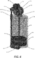
FIG. 4 is a perspective view of the first embodiment of the invention. -
FIG. 5 is a drawing showing one possible embodiment of a wire clip for use with the first embodiment for attaching the wire to the plunger. -
FIG. 6 is a perspective view of the second embodiment of the invention, in which a ribbon is used to pull the plunger through the reservoir. -
FIG. 7 is a top view of the clutch mechanism used with the second embodiment of the invention. - This disclosure presents various systems, components and methods for moving a liquid drug from a liquid reservoir in a drug delivery device to a patient interface, such as a needle or cannula. The embodiments described herein provide one or more advantages over conventional, prior art systems, components and methods, namely, a smaller overall footprint of the drug delivery device.
- Various embodiments of the present invention include systems and methods for delivering a medication to a user using a drug delivery device (sometimes referred to herein as a "pod"), either autonomously, or in accordance with a wireless signal received from an electronic device. In various embodiments, the electronic device may be a user device comprising a smartphone, a smart watch, a smart necklace, a module attached to the drug delivery device, or any other type or sort of electronic device that may be carried by the user or worn on the body of the user and that executes an algorithm that computes the times and dosages of delivery of the medication.
- For example, the user device may execute an "artificial-pancreas" algorithm that computes the times and dosages of delivery of insulin. The user device may also be in communication with a sensor, such as a glucose sensor, that collects data on a physical attribute or condition of the user, such as a glucose level. The sensor may be disposed in or on the body of the user and may be part of the drug delivery device or may be a separate device.
- Alternatively, the drug delivery device may be in communication with the sensor in lieu of or in addition to the communication between the sensor and the user device. The communication may be direct (if, e.g., the sensor is integrated with or otherwise a part of the drug delivery device) or remote/wireless (if, e.g., the sensor is disposed in a different housing than the drug delivery device). In these embodiments, the drug delivery device contains computing hardware (e.g., a processor, memory, firmware, etc.) that executes some or all of the algorithm that computes the times and dosages of delivery of the medication.
-
FIG. 1 illustrates a functional block diagram of an exemplarydrug delivery system 100 suitable for implementing the systems and methods described herein. Thedrug delivery system 100 may implement (and/or provide functionality for) a medication delivery algorithm, such as an artificial pancreas (AP) application, to govern or control the automated delivery of a drug or medication, such as insulin, to a user (e.g., to maintain euglycemia - a normal level of glucose in the blood). Thedrug delivery system 100 may be an automated drug delivery system that may include a drug delivery device 102 (which may be wearable), an analyte sensor 108 (which may also be wearable), and a user device 105. -
Drug delivery system 100, in an optional example, may also include anaccessory device 106, such as a smartwatch, a personal assistant device, or the like, which may communicate with the other components ofsystem 100 via either a wired or wireless communication links 191-193. - The user device 105 may be a computing device such as a smartphone, a tablet, a personal diabetes management (PDM) device, a dedicated diabetes therapy management device, or the like. In an example, user device 105 may include a
processor 151,device memory 153, a user interface 158, and acommunication interface 154. The user device 105 may also contain analog and/or digital circuitry that may be implemented as aprocessor 151 for executing processes based on programming code stored indevice memory 153, such asuser application 160 to manage a user's blood glucose levels and for controlling the delivery of the drug, medication, or therapeutic agent to the user, as well for providing other functions, such as calculating carbohydrate-compensation dosage, a correction bolus dosage and the like as discussed below. The user device 105 may be used to program, adjust settings, and/or control operation ofdrug delivery device 102 and/or the analyte sensor 103 as well as the optional smartaccessory device 106. - The
processor 151 may also be configured to execute programming code stored indevice memory 153, such as theuser app 160. Theuser app 160 may be a computer application that is operable to deliver a drug based on information received from the analyte sensor 103, the cloud-basedservices 111 and/or the user device 105 oroptional accessory device 106. Thememory 153 may also store programming code to, for example, operate the user interface 158 (e.g., a touchscreen device, a camera or the like), thecommunication interface 154 and the like. Theprocessor 151, when executinguser app 160, may be configured to implement indications and notifications related to meal ingestion, blood glucose measurements, and the like. The user interface 158 may be under the control of theprocessor 151 and be configured to present a graphical user interface that enables the input of a meal announcement, adjust setting selections and the like as described herein. - In a specific example, when the
user app 160 is an AP application, theprocessor 151 is also configured to execute a diabetes treatment plan (which may be stored in a memory) that is managed byuser app 160. In addition to the functions mentioned above, whenuser app 160 is an AP application, it may further provide functionality to determine a carbohydrate-compensation dosage, a correction bolus dosage and determine a basal dosage according to a diabetes treatment plan. In addition, as an AP application,user app 160 provides functionality to output signals to thedrug delivery device 102 viacommunications interface 154 to deliver the determined bolus and basal dosages. - The
communication interface 154 may include one or more transceivers that operate according to one or more radio-frequency protocols. In one embodiment, the transceivers may comprise a cellular transceiver and a Bluetooth® transceiver. Thecommunication interface 154 may be configured to receive and transmit signals containing information usable byuser app 160. - User device 105 may be further provided with one or
more output devices 155 which may be, for example, a speaker or a vibration transducer, to provide various signals to the user. - In various exemplary embodiments,
drug delivery device 102 may include areservoir 124 anddrive mechanism 125, which are controllable bycontroller 121, executing a medication delivery algorithm (MDA) 129 stored inmemory 123. Alternatively,controller 121 may act to controlreservoir 124 anddrive mechanism 125 based on signals received fromuser app 160 executing on a user device 105 and communicated todrug delivery device 102 viacommunication link 194.Drive mechanism 125 operates to longitudinally translate a plunger through the reservoir, such as to force the liquid drug through an outlet fluid port to needle /cannula 186. - In an alternate embodiment,
drug delivery device 102 may also include an optional second reservoir 124-2 and second drive mechanism 125-2 which enables the independent delivery of two different liquid drugs. As an example,reservoir 124 may be filled with insulin, while reservoir 124-2 may be filled with Pramlintide or GLP-1. In some embodiments, each ofreservoirs 124, 124-2 may be configured with aseparate drive mechanism 125, 125-2, respectively, which may be separately controllable bycontroller 121 under the direction ofMDA 129. Bothreservoirs 124, 124-2 may be connected to a common needle /cannula 186. -
Drug delivery device 102 may be optionally configured with auser interface 127 providing a means for receiving input from the user and a means for outputting information to the user.User interface 127 may include, for example, light-emitting diodes, buttons on a housing ofdrug delivery device 102, a sound transducer, a micro-display, a microphone, an accelerometer for detecting motions of the device or user gestures (e.g., tapping on a housing of the device) or any other type of interface device that is configured to allow a user to enter information and/or allowdrug delivery device 102 to output information for presentation to the user (e.g., alarm signals or the like). -
Drug delivery device 102 includes apatient interface 186 for interfacing with the user to deliver the liquid drug. Patient interface may be, for example, a needle or cannula for delivering the drug into the body of the user (which may be done subcutaneously, intraperitoneally, or intravenously).Drug delivery device 102 further includes a mechanism for inserting the needle /cannula 186 into the body of the user, which may be integral with or attachable todrug delivery device 102. The insertion mechanism may comprise, in one embodiment, an actuator that inserts the needle /cannula 186 under the skin of the user and thereafter retracts the needle, leaving the cannula in place. - In one embodiment,
drug delivery device 102 includes acommunication interface 126, which may be a transceiver that operates according to one or more radio-frequency protocols, such as Bluetooth®, Wi-Fi, near-field communication, cellular, or the like. Thecontroller 121 may, for example, communicate with user device 105 and ananalyte sensor 108 via thecommunication interface 126. - In some embodiments,
drug delivery device 102 may be provided with one ormore sensors 184. Thesensors 184 may include one or more of a pressure sensor, a power sensor, or the like that are communicatively coupled to thecontroller 121 and provide various signals. For example, a pressure sensor may be configured to provide an indication of the fluid pressure detected in a fluid pathway between thepatient interface 186 andreservoir 124. The pressure sensor may be coupled to or integral with the actuator for inserting thepatient interface 186 into the user. In an example, thecontroller 121 may be operable to determine a rate of drug infusion based on the indication of the fluid pressure. The rate of drug infusion may be compared to an infusion rate threshold, and the comparison result may be usable in determining an amount of insulin onboard (IOB) or a total daily insulin (TDI) amount. In one embodiment,analyte sensor 108 may be integral withdrug delivery device 102. -
Drug delivery device 102 further includes apower source 128, such as a battery, a piezoelectric device, an energy harvesting device, or the like, for supplying electrical power tocontroller 121,memory 123, drivemechanisms 125 and/or other components ofdrug delivery device 102. -
Drug delivery device 102 may be configured to perform and execute processes required to deliver doses of the medication to the user without input from the user device 105 or theoptional accessory device 106. As explained in more detail,MDA 129 may be operable, for example, to determine an amount of insulin to be delivered, IOB, insulin remaining, and the like and to causecontroller 121 to activatedrive mechanism 125 to deliver the medication fromreservoir 124.MDA 129 may take as input data received from theanalyte sensor 108 or fromuser app 160. - The
reservoirs 124, 124-2 may be configured to store drugs, medications or therapeutic agents suitable for automated delivery, such as insulin, Pramlintide, GLP-1, co-formulations of insulin and GLP-1, morphine, blood pressure medicines, chemotherapy drugs, fertility drugs or the like. -
Drug delivery device 102 may be a wearable device and may be attached to the body of a user, such as a patient or diabetic, at an attachment location and may deliver any therapeutic agent, including any drug or medicine, such as insulin or the like, to a user at or around the attachment location. A surface ofdrug delivery device 102 may include an adhesive to facilitate attachment to the skin of a user. - When configured to communicate with an external device, such as the user device 105 or the
analyte sensor 108,drug delivery device 102 may receive signals over the wired or wireless link 194 from the user device 105 or from theanalyte sensor 108. Thecontroller 121 ofdrug delivery device 102 may receive and process the signals from the respective external devices as well as implementing delivery of a drug to the user according to a diabetes treatment plan or other drug delivery regimen. - Optional accessory device 107 may be, a wearable smart device, for example, a smart watch (e.g., an Apple Watch®), smart eyeglasses, smart jewelry, a global positioning system-enabled wearable, a wearable fitness device, smart clothing, or the like. Similar to user device 105, the accessory device 107 may also be configured to perform various functions including controlling
drug delivery device 102. For example, the accessory device 107 may include acommunication interface 174, aprocessor 171, auser interface 178 and amemory 173. Theuser interface 178 may be a graphical user interface presented on a touchscreen display of the smart accessory device 107. Thememory 173 may store programming code to operate different functions of the smart accessory device 107 as well as an instance of theuser app 160, or a pared-down version ofuser app 160 with reduced functionality. In some instances, accessory device 107 may also include sensors of various types. - The
analyte sensor 108 may include acontroller 131, amemory 132, a sensing/measuring device 133, anoptional user interface 137, a power source/energy harvesting circuitry 134, and acommunication interface 135. Theanalyte sensor 108 may be communicatively coupled to theprocessor 151 of the management device 105 orcontroller 121 ofdrug delivery device 102. Thememory 132 may be configured to store information andprogramming code 136. - The
analyte sensor 108 may be configured to detect multiple different analytes, such as glucose, lactate, ketones, uric acid, sodium, potassium, alcohol levels or the like, and output results of the detections, such as measurement values or the like. Theanalyte sensor 108 may, in an exemplary embodiment, be configured to measure a blood glucose value at a predetermined time interval, such as every 5 minutes, every 1 minute, or the like. Thecommunication interface 135 ofanalyte sensor 108 may have circuitry that operates as a transceiver for communicating the measured blood glucose values to the user device 105 over awireless link 195 or withdrug delivery device 102 over thewireless communication link 108. While referred to herein as ananalyte sensor 108, the sensing/measuring device 133 of theanalyte sensor 108 may include one or more additional sensing elements, such as a glucose measurement element, a heart rate monitor, a pressure sensor, or the like. Thecontroller 131 may include discrete, specialized logic and/or components, an application-specific integrated circuit, a microcontroller or processor that executes software instructions, firmware, programming instructions stored in memory (such as memory 132), or any combination thereof. - Similar to the
controller 121 ofdrug delivery device 102, thecontroller 131 of theanalyte sensor 108 may be operable to perform many functions. For example, thecontroller 131 may be configured byprogramming code 136 to manage the collection and analysis of data detected by the sensing and measuringdevice 133. - Although the
analyte sensor 108 is depicted inFIG. 1 as separate fromdrug delivery device 102, in various embodiments, theanalyte sensor 108 anddrug delivery device 102 may be incorporated into the same unit. That is, in various examples, theanalyte sensor 108 may be a part of and integral withdrug delivery device 102 and contained within the same housing asdrug delivery device 102 or an attachable housing thereto. In such an example configuration, thecontroller 121 may be able to implement the functions required for the proper delivery of the medication alone without any external inputs from user device 105, the cloud-basedservices 111, another sensor (not shown), theoptional accessory device 106, or the like. -
Drug delivery system 100 may communicate with or receive services from cloud-basedservices 111. Services provided by cloud-basedservices 111 may include data storage that stores personal or anonymized data, such as blood glucose measurement values, historical IOB or TDI, prior carbohydrate-compensation dosage, and other forms of data. In addition, the cloud-basedservices 111 may process anonymized data from multiple users to provide generalized information related to TDI, insulin sensitivity, IOB and the like. The communication link 115 that couples the cloud-basedservices 111 to therespective devices system 100 may be a cellular link, a Wi-Fi link, a Bluetooth® link, or a combination thereof. - The wireless communication links 115 and 191-196 may be any type of wireless link operating using known wireless communication standards or proprietary standards. As an example, the wireless communication links 191-196 may provide communication links based on Bluetooth®, Zigbee®, Wi-Fi, a near-field communication standard, a cellular standard, or any other wireless protocol via the
respective communication interfaces - In an operational example,
user application 160 implements a graphical user interface that is the primary interface with the user and is used to start and stopdrug delivery device 102, program basal and bolus calculator settings for manual mode as well as program settings specific for automated mode (hybrid closed-loop or closed-loop). -
User app 160, provides a graphical user interface 158 that allows for the use of large text, graphics, and on-screen instructions to prompt the user through the set-up processes and the use ofsystem 100. It will also be used to program the user's custom basal insulin delivery profile, check the status, ofdrug delivery device 102, initiate bolus doses of insulin, make changes to a patient's insulin delivery profile, handle system alerts and alarms, and allow the user to switch between automated mode and manual mode. -
User app 160 may configured to operate in a manual mode in whichuser app 160 will deliver insulin at programmed basal rates and bolus amounts with the option to set temporary basal profiles. Thecontroller 121 will also have the ability to function as a sensor-augmented pump in manual mode, using sensor glucose data provided by theanalyte sensor 108 to populate the bolus calculator. -
User app 160 may configured to operate in an automated mode in whichuser app 160 supports the use of multiple target blood glucose values. For example, in one embodiment, target blood glucose values can range from 110-150 mg/dL, in 10 mg/dL increments, in 5 mg/dL increments, or other increments, but preferably 10 mg/dL increments. The experience for the user will reflect current setup flows whereby the healthcare provider assists the user to program basal rates, glucose targets and bolus calculator settings. These in turn will inform theuser app 160 for insulin dosing parameters. The insulin dosing parameters will be adapted over time based on the total daily insulin (TDI) delivered during each use ofdrug delivery device 102. A temporary hypoglycemia protection mode may be implemented by the user for various time durations in automated mode. With hypoglycemia protection mode, the algorithm reduces insulin delivery and is intended for use over temporary durations when insulin sensitivity is expected to be higher, such as during exercise. - The user app 160 (or MDA 129) may provide periodic insulin micro-boluses based upon past glucose measurements and/or a predicted glucose over a prediction horizon (e.g., 60 minutes). Optimal post-prandial control may require the user to give meal boluses in the same manner as current pump therapy, but normal operation of the
user app 160 will compensate for missed meal boluses and mitigate prolonged hyperglycemia. Theuser app 160 uses a control-to-target strategy that attempts to achieve and maintain a set target glucose value, thereby reducing the duration of prolonged hyperglycemia and hypoglycemia. - In some embodiments, user device 105 and the
analyte sensor 108 may not communicate directly with one another. Instead, data (e.g., blood glucose readings) from analyte sensor may be communicated todrug delivery device 102 vialink 196 and then relayed to user device 105 vialink 194. In some embodiments, to enable communication betweenanalyte sensor 108 and user device 105, the serial number of the analyte sensor must be entered intouser app 160. -
User app 160 may provide the ability to calculate a suggested bolus dose through the use of a bolus calculator. The bolus calculator is provided as a convenience to the user to aid in determining the suggested bolus dose based on ingested carbohydrates, most-recent blood glucose readings (or a blood glucose reading if using fingerstick), programmable correction factor, insulin to carbohydrate ratio, target glucose value and insulin on board (IOB). IOB is estimated byuser app 160 taking into account any manual bolus and insulin delivered by the algorithm. - The invention provides two possible embodiments for
drive mechanism 125, which is responsible for the longitudinal translation of the plunger throughreservoir 124. In general terms, a flexible member is coupled to the plunger and extends through a wall of the reservoir toward which the plunger is being linearly translated. A pulling force on the flexible member causes the plunger to linearly translate toward the end wall of the reservoir, thereby forcing any fluid contained in the reservoir out of the reservoir through a fluid port. - In a first embodiment of the invention is shown in cross-sectional view in
FIG. 3 and in perspective view inFIG. 4 . A fluid, for example, a liquid drug, is contained withinreservoir 302. Thereservoir 302 may, in various embodiments of the invention, be composed of polyethylene or an injection-molded plastic, but, in other embodiments, may be composed of any material impermeable to the fluid disposed therein. - The purpose of
drive mechanism 125 is to moveplunger 304 in direction "A" toward the distal end ofreservoir 302, thereby forcing the fluid through an outlet fluid port (not shown) preferably defined in the distal end ofreservoir 302.Plunger 304 forms a fluid seal betweenplunger 304 and the inner wall ofreservoir 302 by virtue of O-ring 306, which may be composed of any flexible, fluid-impermeable material, for example, rubber. - In this embodiment, the flexible member is a
wire 308 which is rigidly attached toplunger 304 viaclip 316 such that movement ofwire 308 in direction "A" causesplunger 304 to linearly translate within the interior ofreservoir 302 in direction "A" toward the distal end ofreservoir 302.Wire 308 passes throughplunger 304 andseptum 314, which forms a fluid seal betweenwire 308 andplunger 304. In addition,wire 308 also passes throughopening 313 inreservoir 304 which is sealed byseptum 312. - In preferred embodiments of the invention,
wire 308 may be a stranded wire allowing for higher strength-to-flexibility ratio, however, in other embodiments of the invention, a solid wire may be used. In some embodiments,wire 308 is composed of strands of stainless steel or copper, but other materials may also be used. Preferably,wire 308 is covered by a layer of insulation such as to be able to maintain a fluid-tight seal withseptum 314 andseptum 312. In some embodiments, the insulation may be Polytetrafluoroethylene (PTFE), but any other suitable material may also be used. -
Wire 308 is pulled in direction "A" by action ofrollers wire 308 aids in the frictional engagement betweenwire 308 androllers wire 308.Rollers spur gears rollers rollers wire 308. In preferred embodiments of the invention, one or the other ofrollers FIG. 4 ,gear 320 is coupled to gear 328 byroller 326.Gear 328 is coupled to a motor (not shown) directly or via one or more other gears (not shown) such that rotation of the motor will cause a rotational movement of bothgears rollers gear 318 may be the driven gear. - The ends of
wire 308 are coupled bywire crimp 310, such that the wire forms a continuous, taut loop, supported bydummy rollers 322, and extending throughplunger 304 and the interior ofreservoir 302. The taut loop prevents unwanted movement ofplunger 304 in either direction due to, for example, changes in atmospheric pressure or other forces. - In certain embodiments of the invention, a clutch mechanism (not shown) may be provided which will disengage
rollers wire 308 to allowplunger 304 to move in a direction opposite direction "A", to allow filling of the reservoir. In other embodiments, gears 318, 320, may be driven such as to causewire 308 to moveplunger 304 in a direction opposite direction "A". - One possible embodiment of
wire clip 316 is shown inFIG. 5 . In this embodiment,wire 308 is passed throughopening 502 prior towire 308 being formed into a loop by engagement withwire crimp 310.Wire 308 is then slid intoslot 504 such at the edges ofslot 504 engage the insulation ofwire 308, thereby causing a coupling betweenwire clip 316 andwire 308.Wire clip 316 may be permanently attached toplunger 304, by, for example, an adhesive or other means. In other embodiments,wire clip 316 may not be permanently attached toplunger 304 but is nevertheless able to move plunger 30 or by virtue of a force applied by the movement ofwire 308 in direction "A". As would be realized by one of skill in the art,wire clip 316 shown inFIG. 5 is only one possible embodiment of a means for attachingwire 308 toplunger 304. In other embodiments of the invention, any other means may be used to attachwire 308 toplunger 304. - A second embodiment of the invention is shown in perspective view in
FIG. 6 . In this embodiment, the flexible member comprisesribbon 604, which is rigidly attached toplunger 304 by any known means. In preferred embodiments of the invention, theribbon 604 may be composed of a coated fiberglass or metal. In other embodiments of the invention, any other suitable material may be used. -
Ribbon 604 is driven byclutch mechanism 606 which is caused to move in direction "B" by virtue of a threadedengagement 704 withleadscrew 602, as shown in a top view inFIG. 7 . Rotation oflead screw 602 causes movement ofclutch 606 in direction "B" which, in turn, causes the linear translation ofplunger 304 through the interior ofreservoir 302 in direction "A".Leadscrew 602 may be rotationally driven by a motor (not shown) which may be coupled toleadscrew 602 via one or more gears (not shown). -
Ribbon 604 is formed into a taut loop and held in place byguides 608 located at the top and bottom ofreservoir 302. Preferably guides 608 are composed of a low-friction material or may be lubricated to allow the unimpeded movement ofribbon 604 overguides 608. In alternate embodiments of the invention, dummy rollers of the type shown inFIG. 3 asreference number 322 may also be used. -
Cutch mechanism 606 is shown in top view inFIG. 7 .Clutch mechanism 606 comprises ahousing 702 which is in threadedengagement 704 withleadscrew 602.Spring 706 causes movement ofengagement member 708 in direction "C", which causes a frictional engagement ofribbon 604 betweenengagement member 708 andhousing 702, such that the movement ofclutch 606 in direction "B" also causes movement ofribbon 604.Clutch 606 may initially be disengaged fromribbon 604 by, for example, a trigger mechanism (not shown) which holdsengagement member 708 such as to not be frictionally engaged withribbon 604. This allows the free movement ofribbon 604 in either direction so as to allow movement ofplunger 304 in direction "B" to allow filling ofreservoir 302 with the liquid drug. Oncereservoir 302 is full, the trigger mechanism may be tripped, causingengagement member 708 to move in direction "C" by virtue of the action ofspring 706, and into frictional engagement withribbon 604. The exterior surface ofreservoir 302 may define aguide 710 which engageshousing 702 of clutch 606 to guide the movement ofclutch 606 along the exterior ofreservoir 302. - The following examples pertain to various embodiments of the systems and methods disclosed herein for implementation of an automatic drug delivery system dispensing with Pramlintide and insulin.
- Example 1 is a first embodiment of a device comprising a reservoir, a plunger configured to be linearly translated through the reservoir, a flexible member rigidly coupled to the plunger and a drive mechanism for pulling the flexible member to cause the linear translation of the plunger through the reservoir.
- Example 2 is an extension of Example 1, or any other example disclosed herein, wherein the device further comprises a fluid port, defined in the reservoir such that a linear translation of the plunger through the reservoir forces a fluid contained in the reservoir through the fluid port.
- Example 3 is an extension of Example 1, or any other example disclosed herein, wherein the flexible member is a wire.
- Example 4 is an extension of Example 3, or any other example disclosed herein, wherein the device further comprises an opening defined in end of the reservoir and a septum sealing the opening along the wire it passed therethrough.
- Example 5 is an extension of Example 1, or any other example disclosed herein, wherein the drive mechanism comprises a pair of rollers in frictional engagement with the wire and rotating in opposite directions.
- Example 6 is an extension of Example 5, or any other example disclosed herein, wherein the drive mechanism further comprises a gear coupled to each of the rollers, wherein the gears are in rotational engagement with each other.
- Example 7 is an extension of Example 6, or any other example disclosed herein, wherein at least one of the gears is rotationally driven such as to cause a rotation of the rollers in opposite directions.
- Example 8 is an extension of Example 3, wherein the wire is insulated such as to be able to form a fluid seal with the septum.
- Example 9 is an extension of Example 8, or any other example disclosed herein, wherein a circumferential surface of each of the rollers defines the knurled pattern such as to cause a frictional engagement with the insulation of the wire.
- Example 10 is an extension of Example 3, or any other example disclosed herein, wherein the wire is a stranded wire.
- Example 11 is an extension of Example 3, or any other example disclosed herein, wherein the wire forms a complete, taut loop and further wherein the wire passes through the plunger such as to prevent movement of the plunger absent a movement of the wire caused by the drive mechanism.
- Example 12 is an extension of Example 11, or any other example disclosed herein, wherein the device further comprises a plurality of roller members performing the wire into the taut loop.
- Example 13 is extension of Example 1, or any other example disclosed herein, wherein the flexible member is a ribbon.
- Example 14 is an extension of Example 11, or any other example disclosed herein, wherein rotation of the leadscrew causes a linear translation of the clutch mechanism along an outside surface of the reservoir.
- Example 15 is an extension of Example 14, or any other example disclosed herein, wherein the clutch mechanism comprises a housing, a spring in an engagement member, wherein the spring holds ribbon and frictional engagement between the housing in the engagement member.
- Example 16 is extension of Example 15, or any other example disclosed herein, wherein the clutch mechanism further comprises a trigger mechanism for holding the engagement member away from the ribbon such as to allow free movement of the ribbon prior to the trigger mechanism being tripped.
- Example 17 is an extension of Example 14, or any other example disclosed herein, wherein an exterior surface of the reservoir defines a guide thereon for guiding the clutch mechanism along the exterior surface of the reservoir.
- Example 18 is an extension of Example 13, or any other example disclosed herein, wherein the ribbon is composed of coated fiberglass or metal.
- Example 19 is an extension of example 13, or any other example disclosed herein, wherein the ribbon forms a complete, taut loop and further wherein the ribbon passes through the plunger such as to prevent movement of the plunger absent a movement of the ribbon caused by the drive mechanism.
- Example 20 is an extension of Example 19, or any other example disclosed herein, wherein the device further comprises a plurality of rollers performing the ribbon into the taut loop.
- Example 21 is a method of linearly translating the plunger to a reservoir comprising attaching a flexible member to the plunger, the flexible member passing through a wall of the reservoir toward which the plunger is being linearly translated and pulling the flexible member to linearly translate the plunger toward the wall of the reservoir.
- Example 22 is an extension of example 21, or any other example defined herein, wherein the flexible member is an insulated wire or ribbon.
- Software related implementations of the techniques described herein may include, but are not limited to, firmware, application specific software, or any other type of computer readable instructions that may be executed by one or more processors. The computer readable instructions may be provided via non-transitory computer-readable media. Hardware related implementations of the techniques described herein may include, but are not limited to, integrated circuits (ICs), application specific ICs (ASICs), field programmable arrays (FPGAs), and/or programmable logic devices (PLDs). In some examples, the techniques described herein, and/or any system or constituent component described herein may be implemented with a processor executing computer readable instructions stored on one or more memory components.
- To those skilled in the art to which the invention relates, many modifications and adaptations of the invention may be realized. Implementations provided herein, including sizes, shapes, ratings and specifications of various components or arrangements of components, and descriptions of specific manufacturing processes, should be considered exemplary only and are not meant to limit the invention in any way. As one of skill in the art would realize, many variations on implementations discussed herein which fall within the scope of the invention are possible. Moreover, it is to be understood that the features of the various embodiments described herein were not mutually exclusive and can exist in various combinations and permutations, even if such combinations or permutations were not made express herein, without departing from the spirit and scope of the invention. Accordingly, the method and apparatus disclosed herein are not to be taken as limitations on the invention but as an illustration thereof. The scope of the invention is defined by the claims which follow.
- Although the present invention is defined in the attached claims, it should be understood that the present invention can also (alternatively) be defined in accordance with the following embodiments:
- 1. A device comprising:
- a reservoir;
- a plunger configured to be linearly translated through the reservoir;
- a flexible member, rigidly coupled to the plunger; and
- a drive mechanism for pulling the flexible member to cause a linear translation of the plunger through the reservoir.
- 2. The device of embodiment 1, further comprising:
- a fluid port, defined in the reservoir;
- wherein linear translation of the plunger through the reservoir forces a fluid contained in the reservoir through the fluid port.
- 3. The device of embodiment 1, wherein the flexible member is a wire.
- 4. The device of embodiment 3, further comprising:
- an opening, defined in an end of the reservoir; and
- a septum, sealing the opening and allowing the wire to pass therethrough.
- 5. The device of embodiment 3, wherein the drive mechanism comprises:
a pair of rollers in frictional engagement with the wire and rotating in opposite directions. - 6. The device of embodiment 5, further comprising:
- a gear, coupled to each of the rollers;
- wherein the gears are in rotational engagement with each other.
- 7. The device of embodiment 6 wherein at least one of the gears is rotationally driven such as to cause the rotation of the rollers in opposite directions.
- 8. The device of embodiment 3 wherein the wire is insulated such as to be able to form a fluid seal with the septum.
- 9. The device of embodiment 8 wherein a circumferential surface of each of the rollers defines a knurled pattern, such as to cause a frictional engagement with the insulation of the wire.
- 10. The device of embodiment 3 wherein the wire is a stranded wire.
- 11. The device of embodiment 3 wherein the wire forms a complete, taut loop and further wherein the wire passes through the plunger such as to prevent movement of the plunger absent a movement of the wire caused by the drive mechanism.
- 12. The device of embodiment 11 further comprising:
a plurality of roller members for forming the wire into the taut loop. - 13. The device of embodiment 1, wherein the flexible member is a ribbon.
- 14. The device of embodiment 13 wherein the drive mechanism comprises:
- a clutch mechanism engaging the ribbon; and
- a leadscrew in threaded engagement with the clutch mechanism, wherein rotation of the leadscrew causes a linear translation of the clutch mechanism along an outside surface of the reservoir.
- 15. The device of embodiment 14, wherein the clutch mechanism comprises:
- a housing;
- a spring; and
- an engagement member;
- wherein the spring holds the ribbon in frictional engagement between the housing and the engagement member.
- 16. The device of embodiment 15 wherein the clutch mechanism further comprises:
a trigger mechanism for holding the engagement member away from the ribbon such as to allow free movement of the ribbon prior to the trigger mechanism being tripped. - 17. The device of embodiment 14 wherein an exterior surface of the reservoir defines a guide thereon and further wherein the clutch mechanism is engaged with the guide as the clutch mechanism translates linearly along the exterior surface of the reservoir.
- 18. The device of embodiment 13 wherein the ribbon is composed of coated fiberglass or metal.
- 19. The device of embodiment 13 wherein the ribbon forms a complete, taut loop and further wherein the ribbon passes through the plunger such as to prevent movement of the plunger absent a movement of the ribbon caused by the drive mechanism.
- 20. The device of embodiment 19 further comprising:
a plurality of rollers for forming the ribbon into the taut loop. - 21. A method of linearly translating a plunger through a reservoir comprising:
- attaching a flexible member to the plunger, the flexible member passing through a wall of the reservoir toward which the plunger is being linearly translated; and
- pulling the flexible member to linearly translate the plunger toward the wall of the reservoir.
- 22. The method of embodiment 21 wherein the flexible member is an insulated wire or a ribbon.
Claims (15)
- A device comprising:a reservoir;a plunger configured to be linearly translated through the reservoir;a flexible member, rigidly coupled to the plunger; anda drive mechanism for pulling the flexible member to cause a linear translation of the plunger through the reservoir.
- The device of claim 1, further comprising:a fluid port, defined in the reservoir;wherein linear translation of the plunger through the reservoir forces a fluid contained in the reservoir through the fluid port.
- The device of claim 1, wherein the flexible member is a wire.
- The device of claim 3, further comprising:an opening, defined in an end of the reservoir; anda septum, sealing the opening and allowing the wire to pass therethrough.
- The device of claim 3, wherein the drive mechanism comprises:
a pair of rollers in frictional engagement with the wire and rotating in opposite directions. - The device of claim 5, further comprising:a gear, coupled to each of the rollers;wherein the gears are in rotational engagement with each other.
- The device of claim 6 wherein at least one of the gears is rotationally driven such as to cause the rotation of the rollers in opposite directions.
- The device of claim 3 wherein the wire is insulated such as to be able to form a fluid seal with the septum.
- The device of claim 8 wherein a circumferential surface of each of the rollers defines a knurled pattern, such as to cause a frictional engagement with the insulation of the wire.
- The device of claim 3 wherein the wire is a stranded wire.
- The device of claim 3 wherein the wire forms a complete, taut loop and further wherein the wire passes through the plunger such as to prevent movement of the plunger absent a movement of the wire caused by the drive mechanism.
- The device of claim 11 further comprising:
a plurality of roller members for forming the wire into the taut loop. - The device of claim 1, wherein the flexible member is a ribbon.
- The device of claim 13 wherein the drive mechanism comprises:a clutch mechanism engaging the ribbon; anda leadscrew in threaded engagement with the clutch mechanism, wherein rotation of the leadscrew causes a linear translation of the clutch mechanism along an outside surface of the reservoir.
- A method of linearly translating a plunger through a reservoir comprising:attaching a flexible member to the plunger, the flexible member passing through a wall of the reservoir toward which the plunger is being linearly translated; andpulling the flexible member to linearly translate the plunger toward the wall of the reservoir.
Applications Claiming Priority (2)
| Application Number | Priority Date | Filing Date | Title |
|---|---|---|---|
| US202163160240P | 2021-03-12 | 2021-03-12 | |
| US202263306765P | 2022-02-04 | 2022-02-04 |
Publications (1)
| Publication Number | Publication Date |
|---|---|
| EP4056210A1 true EP4056210A1 (en) | 2022-09-14 |
Family
ID=80682784
Family Applications (2)
| Application Number | Title | Priority Date | Filing Date |
|---|---|---|---|
| EP22708661.8A Active EP4304676B1 (en) | 2021-03-12 | 2022-02-17 | Improved drive mechanisms for positive displacement pumps |
| EP22161247.6A Pending EP4056210A1 (en) | 2021-03-12 | 2022-03-10 | Pumping mechanism with wire-pulled plunger |
Family Applications Before (1)
| Application Number | Title | Priority Date | Filing Date |
|---|---|---|---|
| EP22708661.8A Active EP4304676B1 (en) | 2021-03-12 | 2022-02-17 | Improved drive mechanisms for positive displacement pumps |
Country Status (3)
| Country | Link |
|---|---|
| US (2) | US20220288304A1 (en) |
| EP (2) | EP4304676B1 (en) |
| WO (1) | WO2022191972A1 (en) |
Families Citing this family (1)
| Publication number | Priority date | Publication date | Assignee | Title |
|---|---|---|---|---|
| EP4166169A1 (en) * | 2021-10-18 | 2023-04-19 | Insulet Corporation | Flexible linkage for positive displacement pumps |
Citations (6)
| Publication number | Priority date | Publication date | Assignee | Title |
|---|---|---|---|---|
| US20010031947A1 (en) * | 1996-04-30 | 2001-10-18 | Eric R. Waldkoetter | Method and apparatus for drug infusion |
| US6740059B2 (en) | 2000-09-08 | 2004-05-25 | Insulet Corporation | Devices, systems and methods for patient infusion |
| US7303549B2 (en) | 2002-04-23 | 2007-12-04 | Insulet Corporation | Transcutaneous fluid delivery system |
| US20120172804A1 (en) * | 2009-03-31 | 2012-07-05 | Sanofi-Aventis Deutschland Gmbh | Medicament delivery devices |
| US20160278899A1 (en) * | 2013-11-05 | 2016-09-29 | Synagile Corporation | Devices and methods for continuous drug delivery via the mouth |
| EP3508236A1 (en) * | 2018-01-05 | 2019-07-10 | Medicom Innovation Partner a/s | An injection device with a driver mechanism with a spring and a cable |
Family Cites Families (316)
| Publication number | Priority date | Publication date | Assignee | Title |
|---|---|---|---|---|
| CA606281A (en) | 1960-10-04 | Dann Morris | Cartridge for metering syringe | |
| US1441508A (en) | 1921-12-06 | 1923-01-09 | Jensen Anton Marius | Cylindrical slide valve |
| GB357139A (en) | 1929-06-14 | 1931-09-14 | Paul Von Vago | |
| US2198666A (en) | 1936-09-30 | 1940-04-30 | Lakeland Foundation | Syringe |
| DE902776C (en) | 1949-08-17 | 1954-01-28 | August Rooseboom | Automatic injection device with ampoule |
| GB810488A (en) | 1955-03-01 | 1959-03-18 | Eduard Woydt | Liquid pressure piston-engine or reciprocating pump |
| GB875034A (en) | 1957-07-01 | 1961-08-16 | Renault | Improvements in or relating to valves for fluids under pressure |
| US3176712A (en) | 1961-10-03 | 1965-04-06 | Ramsden Clement | Non-return valve |
| US3297260A (en) | 1964-09-21 | 1967-01-10 | Conrad R Barlow | Nozzle and valve assembly |
| US3464359A (en) | 1967-11-13 | 1969-09-02 | Medimeter Corp The | Apparatus for moving fluid from one system to a second system |
| US3505809A (en) | 1968-05-20 | 1970-04-14 | Thermal Hydraulics Corp | Thermal motor |
| DE7121836U (en) | 1970-06-13 | 1972-01-27 | Ismatec Sa | DOSING PISTON PUMP |
| US3786811A (en) * | 1971-08-12 | 1974-01-22 | Medical Dev Corp | Syringe construction |
| US3946732A (en) | 1973-08-08 | 1976-03-30 | Ampoules, Inc. | Two-chamber mixing syringe |
| US3885662A (en) | 1973-12-26 | 1975-05-27 | Ibm | Steerable follower selection mechanism |
| US3947692A (en) | 1974-08-05 | 1976-03-30 | Viron E. Payne, Inc. | Digital transducers |
| IL46017A (en) | 1974-11-07 | 1977-11-30 | Ampoules Inc | Two-chamber mixing syringe |
| US3993061A (en) | 1975-02-28 | 1976-11-23 | Ivac Corporation | Syringe pump drive system and disposable syringe cartridge |
| FR2348709A1 (en) | 1976-04-23 | 1977-11-18 | Pistor Michel | MESOTHERAPIC TREATMENT PROCESS AND INJECTION DEVICE, FORMING AUTOMATIC MICRO-INJECTOR, INCLUDING APPLICATION |
| US4210173A (en) | 1976-12-06 | 1980-07-01 | American Hospital Supply Corporation | Syringe pumping system with valves |
| US4152098A (en) | 1977-01-03 | 1979-05-01 | Clark Ivan P | Micropump |
| DE2749251C3 (en) | 1977-11-03 | 1981-10-08 | Danfoss A/S, 6430 Nordborg | Adjustable heating device for small masses, especially the expansion means in heat setting devices |
| FR2455269A1 (en) | 1978-01-17 | 1980-11-21 | Marceau Serge | Dynamic dosing of liquid food product - utilises compressed air operation of cylinders to move liquid dose to outlet |
| US4221219A (en) | 1978-07-31 | 1980-09-09 | Metal Bellows Corporation | Implantable infusion apparatus and method |
| US4265601A (en) | 1978-09-05 | 1981-05-05 | Harold Mandroian | Three valve precision pump apparatus with head pressure flowthrough protection |
| US4257324A (en) | 1978-10-30 | 1981-03-24 | Bell & Howell Company | Position monitoring methods and apparatus |
| US4277226A (en) | 1979-03-09 | 1981-07-07 | Avi, Inc. | IV Pump with empty supply reservoir and occlusion detector |
| EP0041563A4 (en) | 1979-12-13 | 1982-04-29 | Marvin P Loeb | Wearable insulin infusion system having a tubular reservoir and a positive displacement metering means. |
| US4268150A (en) | 1980-01-28 | 1981-05-19 | Laurence Chen | Disposable camera with simplified film advance and indicator |
| US4313439A (en) | 1980-03-24 | 1982-02-02 | Biotek, Inc. | Automated, spring-powered medicament infusion system |
| CA1169323A (en) | 1980-06-03 | 1984-06-19 | Anthony M. Albisser | Insulin infusion device |
| US4371790A (en) | 1980-09-19 | 1983-02-01 | Rmr Systems, Inc. | Fluid measuring system |
| US4424720A (en) | 1980-12-15 | 1984-01-10 | Ivac Corporation | Mechanism for screw drive and syringe plunger engagement/disengagement |
| IN155982B (en) | 1980-12-31 | 1985-04-20 | Choi Soo Bong | |
| JPS57163309A (en) | 1981-04-01 | 1982-10-07 | Olympus Optical Co Ltd | Capsule apparatus for medical use |
| FR2507637B1 (en) | 1981-06-16 | 1986-09-26 | Libero Elettrotecnica | THERMOELECTRIC ACTUATION DEVICE, IN PARTICULAR FOR ACTIVATING DISPENSERS OF DETERGENTS AND / OR GLOSS AGENTS IN WASHING MACHINES |
| US4435173A (en) | 1982-03-05 | 1984-03-06 | Delta Medical Industries | Variable rate syringe pump for insulin delivery |
| US4498843A (en) | 1982-08-02 | 1985-02-12 | Schneider Philip H | Insulin infusion pump |
| US4551134A (en) | 1982-08-06 | 1985-11-05 | Nuvatec, Inc. | Intravenous set |
| US4475905A (en) | 1982-09-30 | 1984-10-09 | Himmelstrup Anders B | Injection device |
| DE3468173D1 (en) | 1983-09-07 | 1988-02-04 | Disetronic Ag | Portable infusion apparatus |
| NL8303908A (en) | 1983-11-15 | 1985-06-03 | Unilever Nv | METHOD AND APPARATUS FOR THE VOLUMETRIC DOSING OF VISCOUS PRODUCTS |
| US4678408A (en) | 1984-01-06 | 1987-07-07 | Pacesetter Infusion, Ltd. | Solenoid drive apparatus for an external infusion pump |
| US4685903A (en) | 1984-01-06 | 1987-08-11 | Pacesetter Infusion, Ltd. | External infusion pump apparatus |
| US4562751A (en) | 1984-01-06 | 1986-01-07 | Nason Clyde K | Solenoid drive apparatus for an external infusion pump |
| US4684368A (en) | 1984-06-01 | 1987-08-04 | Parker Hannifin Corporation | Inverted pump |
| US4634427A (en) | 1984-09-04 | 1987-01-06 | American Hospital Supply Company | Implantable demand medication delivery assembly |
| US4567549A (en) | 1985-02-21 | 1986-01-28 | Blazer International Corp. | Automatic takeup and overload protection device for shape memory metal actuator |
| US4908017A (en) | 1985-05-14 | 1990-03-13 | Ivion Corporation | Failsafe apparatus and method for effecting syringe drive |
| US4846797A (en) | 1985-05-14 | 1989-07-11 | Intelligent Medicine, Inc. | Syringe positioning device for enhancing fluid flow control |
| DK160633C (en) | 1985-05-15 | 1991-09-02 | Henning Munk Ejlersen | HOSE PUMP, ISSUE FOR EVENING AS INSULIN PUMP |
| US4689042A (en) | 1985-05-20 | 1987-08-25 | Survival Technology, Inc. | Automatic medicament ingredient mixing and injecting apparatus |
| US5349852A (en) | 1986-03-04 | 1994-09-27 | Deka Products Limited Partnership | Pump controller using acoustic spectral analysis |
| US4778451A (en) | 1986-03-04 | 1988-10-18 | Kamen Dean L | Flow control system using boyle's law |
| US4766889A (en) | 1986-06-26 | 1988-08-30 | Medical Engineering Corporation | Infusion erectile system |
| GB8701731D0 (en) | 1987-01-27 | 1987-03-04 | Patcentre Benelux Nv Sa | Pumps |
| WO1988009187A1 (en) | 1987-05-18 | 1988-12-01 | Disetronic Ag | Infusion apparatus |
| US4898579A (en) | 1987-06-26 | 1990-02-06 | Pump Controller Corporation | Infusion pump |
| US4858619A (en) | 1987-06-29 | 1989-08-22 | Toth Marie A | Intracranial pressure monitoring system |
| ATA228987A (en) | 1987-09-09 | 1993-07-15 | Pickhard Ewald | INJECTION DEVICE WITH A DEFORMABLE Vial |
| US5062841A (en) | 1988-08-12 | 1991-11-05 | The Regents Of The University Of California | Implantable, self-regulating mechanochemical insulin pump |
| US5222362A (en) | 1989-01-10 | 1993-06-29 | Maus Daryl D | Heat-activated drug delivery system and thermal actuators therefor |
| US5205819A (en) | 1989-05-11 | 1993-04-27 | Bespak Plc | Pump apparatus for biomedical use |
| US4991743A (en) | 1989-11-06 | 1991-02-12 | Cobe Laboratories, Inc. | Controlled flow accumulator |
| US5020325A (en) | 1990-02-13 | 1991-06-04 | Procedes Vernet | Heat motor |
| US5097122A (en) | 1990-04-16 | 1992-03-17 | Pacesetter Infusion, Ltd. | Medication infusion system having optical motion sensor to detect drive mechanism malfunction |
| US5007458A (en) | 1990-04-23 | 1991-04-16 | Parker Hannifin Corporation | Poppet diaphragm valve |
| JPH0451966A (en) | 1990-06-19 | 1992-02-20 | Toichi Ishikawa | Medical fluid continuous injector |
| GB9027859D0 (en) | 1990-12-21 | 1991-02-13 | Cmb Foodcan Plc | Metering apparatus |
| US5236416A (en) | 1991-05-23 | 1993-08-17 | Ivac Corporation | Syringe plunger position detection and alarm generation |
| US5213483A (en) | 1991-06-19 | 1993-05-25 | Strato Medical Corporation | Peristaltic infusion pump with removable cassette and mechanically keyed tube set |
| DE4129271C1 (en) | 1991-09-03 | 1992-09-17 | Fresenius Ag, 6380 Bad Homburg, De | |
| DE4200595C2 (en) | 1992-01-13 | 1994-10-13 | Michail Efune | Assembly for the infusion set for an insulin pump |
| US5911716A (en) | 1992-01-24 | 1999-06-15 | I-Flow Corporation | Platen pump |
| US5267956A (en) | 1992-02-05 | 1993-12-07 | Alcon Surgical, Inc. | Surgical cassette |
| DK47992D0 (en) | 1992-04-10 | 1992-04-10 | Novo Nordisk As | APPARATUS |
| US5261884A (en) | 1992-04-29 | 1993-11-16 | Becton, Dickinson And Company | Syringe pump control system |
| US5346476A (en) | 1992-04-29 | 1994-09-13 | Edward E. Elson | Fluid delivery system |
| JPH0663133A (en) | 1992-06-18 | 1994-03-08 | Raifu Technol Kenkyusho | Portable automatic chemical injection device |
| US6068615A (en) | 1994-07-22 | 2000-05-30 | Health Hero Network, Inc. | Inductance-based dose measurement in syringes |
| DE4241943C2 (en) | 1992-12-11 | 1994-12-01 | Busak & Luyken Gmbh & Co | Closure means and sealing valve for container openings |
| CH685461B5 (en) | 1993-01-05 | 1996-01-31 | Jean Claude Berney | liquid substances therapeutic infusion sets and portable device comprising such a device. |
| US5433710A (en) | 1993-03-16 | 1995-07-18 | Minimed, Inc. | Medication infusion pump with fluoropolymer valve seat |
| DE4310808C2 (en) | 1993-04-02 | 1995-06-22 | Boehringer Mannheim Gmbh | Liquid dosing system |
| JP3381301B2 (en) | 1993-04-14 | 2003-02-24 | 株式会社ジェイ・エム・エス | Syringe pump |
| US5261882A (en) | 1993-04-26 | 1993-11-16 | Sealfon Andrew I | Negator spring-powered syringe |
| DE69415549T2 (en) | 1993-10-04 | 1999-08-19 | Res International | MICROMACHINE LIQUID FLOW REGULATOR |
| US5807075A (en) | 1993-11-23 | 1998-09-15 | Sarcos, Inc. | Disposable ambulatory microprocessor controlled volumetric pump |
| US5582593A (en) | 1994-07-21 | 1996-12-10 | Hultman; Barry W. | Ambulatory medication delivery system |
| US5520661A (en) | 1994-07-25 | 1996-05-28 | Baxter International Inc. | Fluid flow regulator |
| CA2154937A1 (en) | 1994-07-29 | 1996-01-30 | John C. Tanner | System for administration of a liquid agent to a patient with a syringe pump |
| JPH0858897A (en) | 1994-08-12 | 1996-03-05 | Japan Storage Battery Co Ltd | Fluid supply device |
| US5637095A (en) * | 1995-01-13 | 1997-06-10 | Minimed Inc. | Medication infusion pump with flexible drive plunger |
| US5665070A (en) | 1995-01-19 | 1997-09-09 | I-Flow Corporation | Infusion pump with magnetic bag compression |
| JP2697663B2 (en) | 1995-03-04 | 1998-01-14 | 株式会社ニッショー | Multiple chemical solution injection tool |
| FR2731475B1 (en) | 1995-03-07 | 1997-05-30 | Thomson Dauphinoise | DEVICE FOR MOUNTING AN ELECTRIC HEATING AND / OR COOLING COMPONENT ON A THERMAL CYLINDER |
| US5503628A (en) | 1995-03-15 | 1996-04-02 | Jettek, Inc. | Patient-fillable hypodermic jet injector |
| WO1996032887A1 (en) | 1995-04-20 | 1996-10-24 | Invasatec, Inc. | Radiographic contrast material injector |
| US5618269A (en) | 1995-05-04 | 1997-04-08 | Sarcos, Inc. | Pressure-driven attachable topical fluid delivery system |
| WO1997005385A1 (en) | 1995-07-27 | 1997-02-13 | Seiko Epson Corporation | Microvalve and method of manufacturing the same, micropump using the microvalve and method of manufacturing the same, and apparatus using the micropump |
| US5779676A (en) | 1995-10-11 | 1998-07-14 | Science Incorporated | Fluid delivery device with bolus injection site |
| US5776103A (en) | 1995-10-11 | 1998-07-07 | Science Incorporated | Fluid delivery device with bolus injection site |
| US6050457A (en) | 1995-12-06 | 2000-04-18 | The Procter & Gamble Company | High pressure manually-actuated spray pump |
| US5628309A (en) | 1996-01-25 | 1997-05-13 | Raya Systems, Inc. | Meter for electrically measuring and recording injection syringe doses |
| GB9606829D0 (en) | 1996-03-30 | 1996-06-05 | Jeffrey Peter | Supplying materials etc |
| US5785688A (en) | 1996-05-07 | 1998-07-28 | Ceramatec, Inc. | Fluid delivery apparatus and method |
| IL118689A (en) | 1996-06-20 | 2000-10-31 | Gadot Amir | Intravenous infusion apparatus |
| US5748827A (en) | 1996-10-23 | 1998-05-05 | University Of Washington | Two-stage kinematic mount |
| US6883778B1 (en) | 1996-11-18 | 2005-04-26 | Nypro Inc. | Apparatus for reducing fluid drawback through a medical valve |
| KR0138353Y1 (en) | 1996-12-13 | 1999-04-01 | 주식회사부윤테크 | Syringe device |
| CH692240A5 (en) | 1997-03-26 | 2002-04-15 | Disetronic Licensing Ag | Catheter system for transdermal passage devices. |
| CN1179983A (en) | 1997-06-03 | 1998-04-29 | 王坤山 | Medical device composed of elastic valve type bottle plug and puncture needle |
| DE19723648C1 (en) | 1997-06-05 | 1998-08-27 | Disetronic Licensing Ag | Controlled infusion equipment with leak and reverse flow prevention used e.g. in insulin therapy |
| US5954643A (en) | 1997-06-09 | 1999-09-21 | Minimid Inc. | Insertion set for a transcutaneous sensor |
| US5957890A (en) | 1997-06-09 | 1999-09-28 | Minimed Inc. | Constant flow medication infusion pump |
| US6200293B1 (en) | 1997-08-27 | 2001-03-13 | Science Incorporated | Fluid delivery device with temperature controlled energy source |
| US6485462B1 (en) | 1997-08-27 | 2002-11-26 | Science Incorporated | Fluid delivery device with heat activated energy source |
| US6527744B1 (en) | 1997-08-27 | 2003-03-04 | Science Incorporated | Fluid delivery device with light activated energy source |
| US5961492A (en) | 1997-08-27 | 1999-10-05 | Science Incorporated | Fluid delivery device with temperature controlled energy source |
| US6569115B1 (en) | 1997-08-28 | 2003-05-27 | Mdc Investment Holdings, Inc. | Pre-filled retractable needle injection device |
| AU9295498A (en) | 1997-08-29 | 1999-03-16 | Cycle-Ops Products, Inc. | Exercise resistance device |
| US6019747A (en) | 1997-10-21 | 2000-02-01 | I-Flow Corporation | Spring-actuated infusion syringe |
| US5897530A (en) | 1997-12-24 | 1999-04-27 | Baxter International Inc. | Enclosed ambulatory pump |
| US6159188A (en) | 1998-01-14 | 2000-12-12 | Robert L. Rogers | Apparatus and method for delivery of micro and submicro quantities of materials |
| US6539286B1 (en) | 1998-01-26 | 2003-03-25 | Micron Technology, Inc. | Fluid level sensor |
| AU2570999A (en) | 1998-02-02 | 1999-08-16 | Medtronic, Inc. | Implantable drug infusion device having a safety valve |
| ATE254938T1 (en) | 1998-03-23 | 2003-12-15 | Elan Corp Plc | DEVICE FOR DRUG ADMINISTRATION |
| US5919167A (en) | 1998-04-08 | 1999-07-06 | Ferring Pharmaceuticals | Disposable micropump |
| EP1082151A1 (en) | 1998-06-04 | 2001-03-14 | ELAN CORPORATION, Plc | Gas driven drug delivery device |
| US5906597A (en) | 1998-06-09 | 1999-05-25 | I-Flow Corporation | Patient-controlled drug administration device |
| US5993423A (en) | 1998-08-18 | 1999-11-30 | Choi; Soo Bong | Portable automatic syringe device and injection needle unit thereof |
| KR20010081028A (en) | 1998-11-18 | 2001-08-25 | 추후제출 | Portable device and method for the mobile supply of medicaments with wireless transmission of data for control or programming purposes |
| US6375638B2 (en) | 1999-02-12 | 2002-04-23 | Medtronic Minimed, Inc. | Incremental motion pump mechanisms powered by shape memory alloy wire or the like |
| US20040069044A1 (en) | 1999-04-29 | 2004-04-15 | Gilad Lavi | Device for measuring a volume of drug |
| JP2003501156A (en) | 1999-06-08 | 2003-01-14 | メディカル リサーチ グループ インコーポレイテッド | Liquid injection method and device using chemical reaction in implantable injection device |
| NZ533466A (en) | 1999-06-28 | 2005-10-28 | California Inst Of Techn | Microfabricated elastomeric valve and pump systems |
| US6813519B2 (en) | 2000-01-21 | 2004-11-02 | Medtronic Minimed, Inc. | Ambulatory medical apparatus and method using a robust communication protocol |
| US7003336B2 (en) | 2000-02-10 | 2006-02-21 | Medtronic Minimed, Inc. | Analyte sensor method of making the same |
| AU2001250924A1 (en) | 2000-03-22 | 2001-10-03 | Docusys, Inc. | A drug delivery and monitoring system |
| TW523415B (en) | 2000-03-24 | 2003-03-11 | Novo Nordisk As | A flexible piston rod |
| US6485461B1 (en) | 2000-04-04 | 2002-11-26 | Insulet, Inc. | Disposable infusion device |
| US6585699B2 (en) | 2000-04-13 | 2003-07-01 | Nna/S | Drug delivery device provided with a one-way mechanism |
| US6494433B2 (en) | 2000-06-06 | 2002-12-17 | The Regents Of The University Of Michigan | Thermally activated polymer device |
| US6589229B1 (en) | 2000-07-31 | 2003-07-08 | Becton, Dickinson And Company | Wearable, self-contained drug infusion device |
| US6363609B1 (en) | 2000-10-20 | 2002-04-02 | Short Block Technologies, Inc. | Method and apparatus for aligning crankshaft sections |
| EP1334279A1 (en) | 2000-11-06 | 2003-08-13 | Nanostream, Inc. | Uni-directional flow microfluidic components |
| DK1695727T3 (en) | 2000-11-09 | 2008-12-01 | Insulet Corp | Device for transcutaneous administration |
| US6537249B2 (en) | 2000-12-18 | 2003-03-25 | Science, Incorporated | Multiple canopy |
| EP1364125A1 (en) | 2001-01-17 | 2003-11-26 | M 2 Medical A/S | Shape memory alloy actuator |
| GB0107601D0 (en) | 2001-03-27 | 2001-05-16 | Dca Design Int Ltd | Improvements in and relating to and injection device |
| ATE352334T1 (en) | 2001-05-18 | 2007-02-15 | Deka Products Lp | INFUSION DEVICE FOR A LIQUID PUMP |
| US7235063B2 (en) | 2001-08-21 | 2007-06-26 | D'antonio Consultants International, Inc. | Hypodermic injection system |
| US20040094733A1 (en) | 2001-08-31 | 2004-05-20 | Hower Robert W. | Micro-fluidic system |
| US20030055380A1 (en) | 2001-09-19 | 2003-03-20 | Flaherty J. Christopher | Plunger for patient infusion device |
| NL1019126C1 (en) | 2001-10-05 | 2003-04-08 | Fondse Valves B V | Dosing pump for e.g. measuring intercellular moisture, contains pump chamber with ejector and sliding part for sealing inlet and outlet ports |
| US20040078028A1 (en) | 2001-11-09 | 2004-04-22 | Flaherty J. Christopher | Plunger assembly for patient infusion device |
| US20030109827A1 (en) | 2001-12-07 | 2003-06-12 | Elan Pharma International Limited | Drug delivery system and method |
| US6878136B2 (en) | 2002-02-28 | 2005-04-12 | Medical Product Specialists | Huber needle with anti-rebound safety mechanism |
| US7678084B2 (en) | 2002-03-18 | 2010-03-16 | Eli Lilly And Company | Medication dispensing apparatus with gear set for mechanical advantage |
| CN1375338A (en) | 2002-03-22 | 2002-10-23 | 张�浩 | Heating infusion device |
| US7104275B2 (en) | 2002-04-01 | 2006-09-12 | Emerson Electric Co. | Pinch valve |
| US7052251B2 (en) * | 2002-04-22 | 2006-05-30 | Medtronic Minimed, Inc. | Shape memory alloy wire driven positive displacement micropump with pulsatile output |
| US20050238507A1 (en) | 2002-04-23 | 2005-10-27 | Insulet Corporation | Fluid delivery device |
| US20040153032A1 (en) | 2002-04-23 | 2004-08-05 | Garribotto John T. | Dispenser for patient infusion device |
| US6656158B2 (en) | 2002-04-23 | 2003-12-02 | Insulet Corporation | Dispenser for patient infusion device |
| US6656159B2 (en) | 2002-04-23 | 2003-12-02 | Insulet Corporation | Dispenser for patient infusion device |
| GB0211294D0 (en) | 2002-05-17 | 2002-06-26 | Owen Mumford Ltd | Improvements relating to injection devices |
| US7160272B1 (en) | 2002-05-31 | 2007-01-09 | Elcam Plastic | Y-site medical valve |
| US6723072B2 (en) | 2002-06-06 | 2004-04-20 | Insulet Corporation | Plunger assembly for patient infusion device |
| US20040010207A1 (en) | 2002-07-15 | 2004-01-15 | Flaherty J. Christopher | Self-contained, automatic transcutaneous physiologic sensing system |
| US7018360B2 (en) | 2002-07-16 | 2006-03-28 | Insulet Corporation | Flow restriction system and method for patient infusion device |
| US6749407B2 (en) | 2002-08-22 | 2004-06-15 | Motorola, Inc. | Method of installing valves in a micro-pump |
| EP1403519A1 (en) | 2002-09-27 | 2004-03-31 | Novo Nordisk A/S | Membrane pump with stretchable pump membrane |
| US7144384B2 (en) | 2002-09-30 | 2006-12-05 | Insulet Corporation | Dispenser components and methods for patient infusion device |
| US7128727B2 (en) | 2002-09-30 | 2006-10-31 | Flaherty J Christopher | Components and methods for patient infusion device |
| US20040068224A1 (en) | 2002-10-02 | 2004-04-08 | Couvillon Lucien Alfred | Electroactive polymer actuated medication infusion pumps |
| US7399401B2 (en) | 2002-10-09 | 2008-07-15 | Abbott Diabetes Care, Inc. | Methods for use in assessing a flow condition of a fluid |
| EP1552146B1 (en) | 2002-10-09 | 2011-04-20 | Abbott Diabetes Care Inc. | Fluid delivery device, system and method |
| WO2004056412A2 (en) | 2002-12-23 | 2004-07-08 | M2 Medical A/S | A disposable, wearable insulin dispensing device, a combination of such a device and a programming controller and a method of controlling the operation of such a device |
| JP2004247271A (en) | 2003-02-12 | 2004-09-02 | Bimetal Japan Kk | Voltage sensing switch |
| JP2004274719A (en) | 2003-02-18 | 2004-09-30 | Fujitsu Hitachi Plasma Display Ltd | Predriver circuit, capacitive load drive circuit, and plasma display |
| JP2007525241A (en) | 2003-04-18 | 2007-09-06 | インシュレット コーポレイション | User interface for infusion pump remote control and method of use thereof |
| US20050020980A1 (en) | 2003-06-09 | 2005-01-27 | Yoshio Inoue | Coupling system for an infusion pump |
| DE10327254B4 (en) | 2003-06-17 | 2010-01-28 | Disetronic Licensing Ag | Modular infusion pump |
| JP4047803B2 (en) | 2003-12-25 | 2008-02-13 | 日機装株式会社 | Diaphragm pump |
| NZ585119A (en) | 2004-03-08 | 2011-08-26 | Ichor Medical Systems Inc | Medical injector with surrounding electrical field generating penetrating electrodes |
| US7220245B2 (en) | 2004-05-26 | 2007-05-22 | Kriesel Marshall S | Infusion apparatus |
| US7507221B2 (en) | 2004-10-13 | 2009-03-24 | Mallinckrodt Inc. | Powerhead of a power injection system |
| JP2006159228A (en) | 2004-12-06 | 2006-06-22 | Mitsubishi Heavy Ind Ltd | Brazing method for heat exchanger and preheating apparatus for brazing |
| US7470237B2 (en) | 2005-01-10 | 2008-12-30 | Ethicon Endo-Surgery, Inc. | Biopsy instrument with improved needle penetration |
| US20060173439A1 (en) | 2005-01-18 | 2006-08-03 | Thorne Gale H Jr | Syringe drive system |
| US20060178633A1 (en) | 2005-02-03 | 2006-08-10 | Insulet Corporation | Chassis for fluid delivery device |
| JP4997708B2 (en) | 2005-03-08 | 2012-08-08 | Dic株式会社 | Method for producing fluorinated alkyl group-containing oligomer |
| WO2006104806A2 (en) | 2005-03-28 | 2006-10-05 | Insulet Corporation | Fluid delivery device |
| US7713238B2 (en) | 2005-04-06 | 2010-05-11 | M2 Group Holdings, Inc. | Medicine dispensing device |
| US20060253085A1 (en) | 2005-05-06 | 2006-11-09 | Medtronic Minimed, Inc. | Dual insertion set |
| US7691086B2 (en) | 2005-06-14 | 2010-04-06 | Tengiz Tkebuchava | Catheter for introduction of medications to the tissues of a heart or other organ |
| DE102005040344A1 (en) | 2005-08-25 | 2007-03-01 | Fresenius Kabi Deutschland Gmbh | Pump for use as infusion pump, has delivery bolt or piston supported in housing in movable manner, and drive unit for driving delivery bolt or piston, where movement of delivery bolt or piston is limited by upper and lower end stops |
| US7534226B2 (en) * | 2005-09-26 | 2009-05-19 | M2 Group Holdings, Inc. | Dispensing fluid from an infusion pump system |
| US8105279B2 (en) | 2005-09-26 | 2012-01-31 | M2 Group Holdings, Inc. | Dispensing fluid from an infusion pump system |
| WO2007047279A1 (en) | 2005-10-18 | 2007-04-26 | Richards Cynthia C | Dispenser having a first pump for insulin and a second pump for glucose or glucagon |
| EP2926847B1 (en) | 2005-11-02 | 2022-05-25 | MedicalTree Patents Ltd. | Implantable infusion device with advanceable and retractable needle |
| WO2007054371A1 (en) | 2005-11-14 | 2007-05-18 | Mydata Automation Ab | A jetting apparatus and method of improving the performance of a jetting apparatus by using a flow sensor for measuring the air flow |
| GB2433032A (en) | 2005-12-08 | 2007-06-13 | Owen Mumford Ltd | Syringe with dose adjustment means |
| MX2008010341A (en) | 2006-02-09 | 2008-11-18 | Deka Products Lp | Peripheral systems. |
| AU2007233231B2 (en) | 2006-03-30 | 2011-02-24 | Mannkind Corporation | Multi-cartridge fluid delivery device |
| JP5084825B2 (en) | 2006-05-29 | 2012-11-28 | ノボ・ノルデイスク・エー/エス | Mechanism for injection device |
| US20070282269A1 (en) | 2006-05-31 | 2007-12-06 | Seattle Medical Technologies | Cannula delivery apparatus and method for a disposable infusion device |
| US9119582B2 (en) | 2006-06-30 | 2015-09-01 | Abbott Diabetes Care, Inc. | Integrated analyte sensor and infusion device and methods therefor |
| US7682338B2 (en) | 2006-08-23 | 2010-03-23 | Medtronic Minimed, Inc. | Infusion medium delivery system, device and method with needle inserter and needle inserter device and method |
| US20080172028A1 (en) | 2006-10-17 | 2008-07-17 | Blomquist Michael L | Insulin pump having selectable insulin absorption models |
| GB2456681B (en) | 2006-10-26 | 2009-11-11 | Starbridge Systems Ltd | Pump |
| ITPD20060419A1 (en) | 2006-11-13 | 2008-05-14 | Federico Nalesso | DEVICE FOR THE MAINTENANCE TREATMENT OF CENTRAL VENOUS CATHETERS |
| US7708169B1 (en) * | 2006-11-27 | 2010-05-04 | Szoke Jr Anthony A | Compact powered caulking gun with scissor type dispensing mechanism |
| US8172799B2 (en) | 2007-01-10 | 2012-05-08 | Acist Medical Systems, Inc. | Volumetric pump |
| US8798284B2 (en) | 2007-04-02 | 2014-08-05 | Baxter International Inc. | User selectable masking sounds for medical instruments |
| DE102007018868A1 (en) | 2007-04-19 | 2008-10-23 | Lts Lohmann Therapie-Systeme Ag | Disposable injector with at least one towing hook and a sliding wedge gear for unlocking releasing a locking element |
| US20100152674A1 (en) | 2007-04-30 | 2010-06-17 | Medtronic Minimed, Inc | Needle inserting and fluid flow connection for infusion medium delivery system |
| EP2146760B1 (en) | 2007-04-30 | 2018-10-10 | Medtronic MiniMed, Inc. | Reservoir filling, bubble management, and infusion medium delivery systems and methods with same |
| US8211059B2 (en) | 2007-06-25 | 2012-07-03 | Kriesel Marshall S | Fluid dispenser with additive sub-system |
| JP2010534085A (en) | 2007-07-20 | 2010-11-04 | メディンゴ・リミテッド | Hand operated portable injection device |
| US9968742B2 (en) | 2007-08-29 | 2018-05-15 | Medtronic Minimed, Inc. | Combined sensor and infusion set using separated sites |
| WO2009039203A2 (en) | 2007-09-17 | 2009-03-26 | Satish Sundar | High precision infusion pump controller |
| US8702405B2 (en) | 2007-11-17 | 2014-04-22 | Brian Leonard Verrilli | Twisting translational displacement pump cartridge |
| US7771392B2 (en) | 2007-11-29 | 2010-08-10 | Roche Diagnostics Operations, Inc. | Lead screw delivery device using reusable shape memory actuator drive |
| US8206353B2 (en) | 2008-04-11 | 2012-06-26 | Medtronic Minimed, Inc. | Reservoir barrier layer systems and methods |
| WO2009141005A1 (en) | 2008-05-20 | 2009-11-26 | Tecpharma Licensing Ag | Device for administering an injectable product comprising a residual amount display |
| US8231577B2 (en) | 2008-06-26 | 2012-07-31 | Calibra Medical, Inc. | Disposable infusion device with automatically releasable cannula driver |
| DE102008038751B3 (en) | 2008-08-12 | 2010-04-15 | Fresenius Medical Care Deutschland Gmbh | Reverse osmosis system with a device for noise reduction and method for noise reduction of a reverse osmosis system |
| CA2930329A1 (en) | 2008-08-18 | 2010-02-25 | Calibra Medical, Inc. | Drug infusion system with reusable and disposable components |
| CA2746160C (en) | 2008-12-09 | 2017-02-14 | Becton, Dickinson And Company | Multi-stroke delivery pumping mechanism for a drug delivery device for high pressure injections |
| AU2009324406B2 (en) | 2008-12-12 | 2014-12-11 | Sanofi-Aventis Deutschland Gmbh | Resettable drive mechanism for a medication delivery device and medication delivery device |
| US9370621B2 (en) | 2008-12-16 | 2016-06-21 | Medtronic Minimed, Inc. | Needle insertion systems and methods |
| BRPI1008514A2 (en) | 2009-02-05 | 2016-03-08 | Sanofi Aventis Deutschland | "drug shipping device" |
| US20120136298A1 (en) | 2009-06-04 | 2012-05-31 | Novo Nordisk Healthcare A/G | Mixing device with piston coupling arrangement |
| EP2456975A2 (en) | 2009-07-23 | 2012-05-30 | SwissInnov Product Sàrl | Fluid delivery system comprising a fluid pumping device and a drive system |
| EP2724739B1 (en) | 2009-07-30 | 2015-07-01 | Tandem Diabetes Care, Inc. | Portable infusion pump system |
| US8900190B2 (en) | 2009-09-02 | 2014-12-02 | Medtronic Minimed, Inc. | Insertion device systems and methods |
| US8157769B2 (en) | 2009-09-15 | 2012-04-17 | Medimop Medical Projects Ltd. | Cartridge insertion assembly for drug delivery system |
| BR112012009612A2 (en) | 2009-11-03 | 2016-05-17 | Homann La Roche Ag F | method for removing a fluid medium from a container and device for providing a fluid medium |
| AU2010330032B2 (en) | 2009-12-07 | 2014-07-24 | Sanofi-Aventis Deutschland Gmbh | Drive assembly for a drug delivery device and drug delivery device |
| CN102762243B (en) | 2009-12-14 | 2014-07-23 | Shl集团有限责任公司 | Medicament delivery device |
| US9677555B2 (en) | 2011-12-21 | 2017-06-13 | Deka Products Limited Partnership | System, method, and apparatus for infusing fluid |
| WO2011114285A2 (en) | 2010-03-17 | 2011-09-22 | Sensile Pat Ag | Micropump |
| IL211800A (en) | 2010-03-21 | 2014-03-31 | Isaac Zukier | Device for injecting fluids or gels |
| US8920376B2 (en) | 2010-04-20 | 2014-12-30 | Minipumps, Llc | Fill-status sensors for drug pump devices |
| KR101850687B1 (en) | 2010-04-21 | 2018-04-20 | 애브비 바이오테크놀로지 리미티드 | Wearable automatic injection device for controlled delivery of therapeutic agents |
| EP2397181B1 (en) | 2010-06-18 | 2014-01-15 | F. Hoffmann-La Roche AG | Insertion device having a permanently locking rotating needle cover |
| WO2012037213A1 (en) * | 2010-09-17 | 2012-03-22 | Corindus Inc. | Wheel for robotic catheter system drive mechanism |
| JP6276993B2 (en) | 2010-11-03 | 2018-02-07 | サノフィ−アベンティス・ドイチュラント・ゲゼルシャフト・ミット・ベシュレンクテル・ハフツング | Needle assembly for delivery of at least two drugs |
| GB201020472D0 (en) | 2010-12-02 | 2011-01-19 | Oval Medical Technologies Ltd | A drive assembly for an autoinjector |
| EP2468338A1 (en) | 2010-12-21 | 2012-06-27 | Sanofi-Aventis Deutschland GmbH | Auto-injector |
| US9192716B2 (en) | 2011-03-16 | 2015-11-24 | Sanofi-Aventis Deutschland Gmbh | Drive mechanism for a drug delivery device and drug delivery device |
| BR112013024811A2 (en) | 2011-03-31 | 2016-12-20 | Sanofi Aventis Deutschland | Dosing mechanism and injection device |
| CN103619378B (en) | 2011-04-21 | 2017-03-01 | 艾伯维公司 | wearable automatic injection device |
| JP5853289B2 (en) | 2011-04-26 | 2016-02-09 | 大成化工株式会社 | Elastic seal body for prefilled syringe |
| US8499913B2 (en) | 2011-05-20 | 2013-08-06 | The Boeing Company | Shape memory alloy actuator system and method |
| MX349916B (en) | 2011-09-02 | 2017-08-18 | Unitract Syringe Pty Ltd | Drive mechanism for drug delivery pumps with integrated status indication. |
| JP5861341B2 (en) | 2011-09-12 | 2016-02-16 | 頴 小西 | Pump device |
| EP2572740A1 (en) | 2011-09-20 | 2013-03-27 | Roche Diagnostics GmbH | Drug injection devices and systems with an analyte measurement module |
| JP6109834B2 (en) | 2011-10-07 | 2017-04-05 | ノボ・ノルデイスク・エー/エス | System for determining the position of an element based on a three-axis magnetic sensor |
| US8382703B1 (en) | 2011-10-18 | 2013-02-26 | King Saud University | Piezoelectric dual-syringe insulin pump |
| EP2626097A1 (en) | 2012-02-09 | 2013-08-14 | Arte Corporation | Device for accomodating a freeze-dried pharmaceutical product and method of manufacturing a sealed vessel accomodating a freeze-dried pharmaceutical product |
| JP6006509B2 (en) | 2012-03-08 | 2016-10-12 | 武蔵エンジニアリング株式会社 | Liquid dispensing apparatus and coating apparatus |
| WO2013137893A1 (en) | 2012-03-15 | 2013-09-19 | Becton, Dickinson And Company | Multiple use disposable injection pen |
| DE102012102274B4 (en) | 2012-03-19 | 2018-05-24 | B. Braun Melsungen Ag | piston pump |
| RS65875B1 (en) | 2012-03-30 | 2024-09-30 | Insulet Corp | Fluid delivery device with transcutaneous access tool, insertion mechanism and blood glucose monitoring for use therewith |
| CN104684597A (en) | 2012-08-20 | 2015-06-03 | 霍夫曼-拉罗奇有限公司 | Therapeutic system with an adaptor for an infusion set |
| US20150202386A1 (en) | 2012-08-28 | 2015-07-23 | Osprey Medical, Inc. | Volume monitoring device utilizing hall sensor-based systems |
| MX352388B (en) * | 2012-08-29 | 2017-11-22 | Unitract Syringe Pty Ltd | Variable rate controlled delivery drive mechanisms for drug delivery pumps. |
| JP6098988B2 (en) | 2012-09-28 | 2017-03-22 | 味の素株式会社 | Support-containing prepolymer sheet |
| BR112015008224A2 (en) * | 2012-10-16 | 2017-07-04 | Swissinnov Product Sarl | fluid release device for releasing small amounts of fluid to a patient, system for releasing small amounts of fluid for a patient, detachable adjustable bifunctional connector on the fluid release device and method for installing the fluid release device in a patient |
| HK1210729A1 (en) | 2012-12-10 | 2016-05-06 | Sanofi-Aventis Deutschland Gmbh | Medical pump and method of operating the same |
| DE102012024371A1 (en) | 2012-12-13 | 2014-06-18 | Schott Ag | Storage device Storage of liquid media, in particular medicines and methods for dispensing liquid media |
| US9925331B2 (en) | 2013-03-11 | 2018-03-27 | Boston Scientific Limited | Double action infusion system |
| WO2014139916A1 (en) | 2013-03-13 | 2014-09-18 | Sanofi-Aventis Deutschland Gmbh | Assembly for a drug delivery device comprising a feedback feature |
| US9687346B2 (en) * | 2013-03-14 | 2017-06-27 | Edwards Lifesciences Corporation | Multi-stranded heat set annuloplasty rings |
| US20150367073A1 (en) | 2013-03-15 | 2015-12-24 | Windgap Medical, Llc | Portable Drug Mixing and Delivery Device and Associated Methods |
| SG11201507878SA (en) | 2013-03-22 | 2015-10-29 | Amgen Inc | Injector and method of assembly |
| JP6491195B2 (en) | 2013-05-03 | 2019-03-27 | ベクトン・ディキンソン・アンド・カンパニーBecton, Dickinson And Company | Fluid path subassembly |
| SG11201509810TA (en) | 2013-05-31 | 2015-12-30 | 3M Innovative Properties Co | Microneedle injection and infusion apparatus and method of using same |
| JP6297794B2 (en) | 2013-06-12 | 2018-03-20 | 株式会社ダイセル | Syringe |
| CN110115787A (en) | 2013-08-23 | 2019-08-13 | 尤尼特拉克特注射器公司 | Integrated puncturing for medicine delivery pump seals fluid passage connector and drug container |
| HK1222143A1 (en) | 2013-09-03 | 2017-06-23 | Sanofi | Mechanism for a drug delivery device and drug delivery device comprising the mechanism |
| TR201902021T4 (en) * | 2013-09-05 | 2019-03-21 | Sanofi Aventis Deutschland | Needle insertion and retraction arrangement with manually triggered, spring loaded drive mechanism. |
| EP4442299A3 (en) | 2013-09-30 | 2025-08-13 | Medimop Medical Projects Ltd | Stabilized pen injector |
| EP3068465B1 (en) | 2013-11-15 | 2022-10-26 | Fresenius Kabi USA, LLC | Fluid flow regulator assembly |
| CN109758667B (en) | 2013-12-01 | 2021-07-06 | 贝克顿·迪金森公司 | Medicament device |
| ES2698603T3 (en) | 2013-12-04 | 2019-02-05 | Hoffmann La Roche | Ambulatory infusion system that includes a step-switching mechanism for a control valve |
| JP6647205B2 (en) | 2014-02-06 | 2020-02-14 | ノボ・ノルデイスク・エー/エス | Combined cartridge and needle assembly |
| US10132308B2 (en) | 2014-04-07 | 2018-11-20 | Becton, Dickinson And Company | Rotational metering pump for insulin patch |
| US10004845B2 (en) | 2014-04-18 | 2018-06-26 | Becton, Dickinson And Company | Split piston metering pump |
| US10493201B2 (en) | 2014-04-24 | 2019-12-03 | Becton, Dickinson And Company | Cannula insertion and retraction device for infusion device |
| WO2015164648A1 (en) | 2014-04-24 | 2015-10-29 | Becton, Dickinson And Company | Catheter insertion mechanism for a patch pump |
| KR101524678B1 (en) | 2014-04-29 | 2015-06-03 | 최규동 | Short Length Driver for Injection Appartus |
| JP2017515603A (en) | 2014-05-19 | 2017-06-15 | メディコム・イノベーション・パートナー・アクティーゼルスカブMedicom Innovation Partner A/S | Medical cartridge with one-way valve |
| US9416775B2 (en) | 2014-07-02 | 2016-08-16 | Becton, Dickinson And Company | Internal cam metering pump |
| CA2900913C (en) | 2014-08-20 | 2023-03-21 | Dreamwell, Ltd. | Smart pillows and processes for providing active noise cancellation and biofeedback |
| US11229737B2 (en) | 2014-09-10 | 2022-01-25 | Becton, Dickinson And Company | Activation system and method for on-body medical devices |
| EP3050585B1 (en) | 2015-01-27 | 2019-04-10 | Idorsia Pharmaceuticals Ltd | Dosing device for dispensing a fluid under aseptic conditions |
| GB201600232D0 (en) | 2016-01-06 | 2016-02-17 | Vicentra B V | Fluid delivery system |
| GB201600234D0 (en) | 2016-01-06 | 2016-02-17 | Vicentra B V | Shape memory actuator |
| EP4335471A3 (en) | 2016-01-28 | 2024-08-21 | DEKA Products Limited Partnership | Apparatus for monitoring, regulating, or controlling fluid flow |
| WO2017148855A1 (en) | 2016-03-01 | 2017-09-08 | Novo Nordisk A/S | Switch arrangement for drug delivery device with data capture |
| WO2017176374A1 (en) | 2016-04-06 | 2017-10-12 | Flextronics Ap, Llc | Automatic injection device having a drive system with a shape memory spring |
| GB2549750A (en) | 2016-04-27 | 2017-11-01 | Owen Mumford Ltd | Medicament delivery device |
| CN109310828B (en) | 2016-05-30 | 2022-09-16 | 诺和诺德股份有限公司 | Mounting features for accessory devices |
| US10709845B2 (en) | 2016-07-21 | 2020-07-14 | Amgen Inc. | Drug delivery device with a rotatable drive mechanism |
| WO2018035051A1 (en) | 2016-08-14 | 2018-02-22 | Insulet Corporation | Drug delivery device with detection of position of the plunger |
| EP3354303B1 (en) | 2017-01-31 | 2020-01-08 | Société Industrielle de Sonceboz S.A. | Drug delivery system |
| FR3063015B1 (en) | 2017-02-20 | 2021-10-01 | Aptar France Sas | AUTOMATIC FLUID PRODUCT INJECTION DEVICE. |
| US10792425B2 (en) | 2017-03-03 | 2020-10-06 | Jerry Joseph | Treatment system with automated cannula and sensor inserter, fluid delivery device, and drive mechanism for use therewith |
| US10695485B2 (en) | 2017-03-07 | 2020-06-30 | Insulet Corporation | Very high volume user filled drug delivery device |
| CN107096091A (en) * | 2017-06-08 | 2017-08-29 | 广州欧浦瑞医疗科技有限公司 | A kind of mechanical infusion pressurizer and pressure method |
| US20210236771A1 (en) * | 2018-04-19 | 2021-08-05 | Wake Forest University Health Sciences | A medical device for deploying a catheter that can be operated with a single hand, and a method |
| WO2021016452A1 (en) | 2019-07-25 | 2021-01-28 | Becton, Dickinson And Company | Rotational metering pump for insulin patch |
-
2022
- 2022-02-17 EP EP22708661.8A patent/EP4304676B1/en active Active
- 2022-02-17 WO PCT/US2022/016713 patent/WO2022191972A1/en not_active Ceased
- 2022-02-17 US US17/674,093 patent/US20220288304A1/en active Pending
- 2022-02-17 US US17/674,113 patent/US12616790B2/en active Active
- 2022-03-10 EP EP22161247.6A patent/EP4056210A1/en active Pending
Patent Citations (7)
| Publication number | Priority date | Publication date | Assignee | Title |
|---|---|---|---|---|
| US20010031947A1 (en) * | 1996-04-30 | 2001-10-18 | Eric R. Waldkoetter | Method and apparatus for drug infusion |
| US6740059B2 (en) | 2000-09-08 | 2004-05-25 | Insulet Corporation | Devices, systems and methods for patient infusion |
| US7137964B2 (en) | 2000-09-08 | 2006-11-21 | Insulet Corporation | Devices, systems and methods for patient infusion |
| US7303549B2 (en) | 2002-04-23 | 2007-12-04 | Insulet Corporation | Transcutaneous fluid delivery system |
| US20120172804A1 (en) * | 2009-03-31 | 2012-07-05 | Sanofi-Aventis Deutschland Gmbh | Medicament delivery devices |
| US20160278899A1 (en) * | 2013-11-05 | 2016-09-29 | Synagile Corporation | Devices and methods for continuous drug delivery via the mouth |
| EP3508236A1 (en) * | 2018-01-05 | 2019-07-10 | Medicom Innovation Partner a/s | An injection device with a driver mechanism with a spring and a cable |
Also Published As
| Publication number | Publication date |
|---|---|
| US20220288304A1 (en) | 2022-09-15 |
| US12616790B2 (en) | 2026-05-05 |
| EP4304676A1 (en) | 2024-01-17 |
| US20220288302A1 (en) | 2022-09-15 |
| WO2022191972A1 (en) | 2022-09-15 |
| EP4304676B1 (en) | 2026-04-22 |
Similar Documents
| Publication | Publication Date | Title |
|---|---|---|
| US20190221307A1 (en) | User interface for diabetes management system | |
| EP4166169A1 (en) | Flexible linkage for positive displacement pumps | |
| US12544510B2 (en) | Systems and methods for incorporating co-formulations of insulin in an automatic insulin delivery system | |
| US20260102557A1 (en) | Pump mechanism with double reservoir and stationary fluid ports | |
| AU2026203221A1 (en) | Positive displacement pumping mechanism with double reservoir | |
| US12616790B2 (en) | Pumping mechanism with wire-pulled plunger | |
| US20250099993A1 (en) | Low-friction rolling plunger for a wearable drug delivery device | |
| US20230094194A1 (en) | Dual needle valve for a wearable drug delivery device | |
| US20240075208A1 (en) | Method for detecting occlusions in a fluid path using blood glucose readings | |
| US20230330337A1 (en) | System and method for creating or adjusting manual basal profiles | |
| US20230211077A1 (en) | Pleated expandable reservoir for a wearable drug delivery device | |
| WO2024173164A1 (en) | System and method for reducing cgm warm-up time by application of optical energy | |
| US20240091435A1 (en) | Mechanism providing variable fill capability for a liquid reservoir and pump | |
| US20230117504A1 (en) | Drive mechanism for positive displacement pumps | |
| US20240009390A1 (en) | System and method for detecting occlusions in a fluid path | |
| HK1237289A1 (en) | Glucagon administration system and methods |
Legal Events
| Date | Code | Title | Description |
|---|---|---|---|
| PUAI | Public reference made under article 153(3) epc to a published international application that has entered the european phase |
Free format text: ORIGINAL CODE: 0009012 |
|
| STAA | Information on the status of an ep patent application or granted ep patent |
Free format text: STATUS: REQUEST FOR EXAMINATION WAS MADE |
|
| STAA | Information on the status of an ep patent application or granted ep patent |
Free format text: STATUS: EXAMINATION IS IN PROGRESS |
|
| 17P | Request for examination filed |
Effective date: 20220310 |
|
| AK | Designated contracting states |
Kind code of ref document: A1 Designated state(s): AL AT BE BG CH CY CZ DE DK EE ES FI FR GB GR HR HU IE IS IT LI LT LU LV MC MK MT NL NO PL PT RO RS SE SI SK SM TR |
|
| 17Q | First examination report despatched |
Effective date: 20220818 |
|
| GRAP | Despatch of communication of intention to grant a patent |
Free format text: ORIGINAL CODE: EPIDOSNIGR1 |
|
| STAA | Information on the status of an ep patent application or granted ep patent |
Free format text: STATUS: GRANT OF PATENT IS INTENDED |