EP4055289B1 - Carabiner - Google Patents
Carabiner Download PDFInfo
- Publication number
- EP4055289B1 EP4055289B1 EP20816715.5A EP20816715A EP4055289B1 EP 4055289 B1 EP4055289 B1 EP 4055289B1 EP 20816715 A EP20816715 A EP 20816715A EP 4055289 B1 EP4055289 B1 EP 4055289B1
- Authority
- EP
- European Patent Office
- Prior art keywords
- gate
- locking
- carabiner
- locking collar
- opening
- Prior art date
- Legal status (The legal status is an assumption and is not a legal conclusion. Google has not performed a legal analysis and makes no representation as to the accuracy of the status listed.)
- Active
Links
Images





Classifications
-
- F—MECHANICAL ENGINEERING; LIGHTING; HEATING; WEAPONS; BLASTING
- F16—ENGINEERING ELEMENTS AND UNITS; GENERAL MEASURES FOR PRODUCING AND MAINTAINING EFFECTIVE FUNCTIONING OF MACHINES OR INSTALLATIONS; THERMAL INSULATION IN GENERAL
- F16B—DEVICES FOR FASTENING OR SECURING CONSTRUCTIONAL ELEMENTS OR MACHINE PARTS TOGETHER, e.g. NAILS, BOLTS, CIRCLIPS, CLAMPS, CLIPS OR WEDGES; JOINTS OR JOINTING
- F16B45/00—Hooks; Eyes
- F16B45/02—Hooks with pivoting or elastically bending closing member
- F16B45/027—Hooks with pivoting or elastically bending closing member and having position-locking means for the closing member
-
- F—MECHANICAL ENGINEERING; LIGHTING; HEATING; WEAPONS; BLASTING
- F16—ENGINEERING ELEMENTS AND UNITS; GENERAL MEASURES FOR PRODUCING AND MAINTAINING EFFECTIVE FUNCTIONING OF MACHINES OR INSTALLATIONS; THERMAL INSULATION IN GENERAL
- F16B—DEVICES FOR FASTENING OR SECURING CONSTRUCTIONAL ELEMENTS OR MACHINE PARTS TOGETHER, e.g. NAILS, BOLTS, CIRCLIPS, CLAMPS, CLIPS OR WEDGES; JOINTS OR JOINTING
- F16B45/00—Hooks; Eyes
- F16B45/02—Hooks with pivoting or elastically bending closing member
- F16B45/023—Hooks with pivoting or elastically bending closing member the closing member pivoting about an axis perpendicular to the plane of the hook
-
- F—MECHANICAL ENGINEERING; LIGHTING; HEATING; WEAPONS; BLASTING
- F16—ENGINEERING ELEMENTS AND UNITS; GENERAL MEASURES FOR PRODUCING AND MAINTAINING EFFECTIVE FUNCTIONING OF MACHINES OR INSTALLATIONS; THERMAL INSULATION IN GENERAL
- F16B—DEVICES FOR FASTENING OR SECURING CONSTRUCTIONAL ELEMENTS OR MACHINE PARTS TOGETHER, e.g. NAILS, BOLTS, CIRCLIPS, CLAMPS, CLIPS OR WEDGES; JOINTS OR JOINTING
- F16B45/00—Hooks; Eyes
- F16B45/02—Hooks with pivoting or elastically bending closing member
- F16B45/027—Hooks with pivoting or elastically bending closing member and having position-locking means for the closing member
- F16B45/028—Hooks with pivoting or elastically bending closing member and having position-locking means for the closing member the position-locking means being pivotally connected
-
- F—MECHANICAL ENGINEERING; LIGHTING; HEATING; WEAPONS; BLASTING
- F16—ENGINEERING ELEMENTS AND UNITS; GENERAL MEASURES FOR PRODUCING AND MAINTAINING EFFECTIVE FUNCTIONING OF MACHINES OR INSTALLATIONS; THERMAL INSULATION IN GENERAL
- F16B—DEVICES FOR FASTENING OR SECURING CONSTRUCTIONAL ELEMENTS OR MACHINE PARTS TOGETHER, e.g. NAILS, BOLTS, CIRCLIPS, CLAMPS, CLIPS OR WEDGES; JOINTS OR JOINTING
- F16B45/00—Hooks; Eyes
- F16B45/02—Hooks with pivoting or elastically bending closing member
- F16B45/027—Hooks with pivoting or elastically bending closing member and having position-locking means for the closing member
- F16B45/029—Hooks with pivoting or elastically bending closing member and having position-locking means for the closing member the position-locking means being slidably mounted
-
- F—MECHANICAL ENGINEERING; LIGHTING; HEATING; WEAPONS; BLASTING
- F16—ENGINEERING ELEMENTS AND UNITS; GENERAL MEASURES FOR PRODUCING AND MAINTAINING EFFECTIVE FUNCTIONING OF MACHINES OR INSTALLATIONS; THERMAL INSULATION IN GENERAL
- F16B—DEVICES FOR FASTENING OR SECURING CONSTRUCTIONAL ELEMENTS OR MACHINE PARTS TOGETHER, e.g. NAILS, BOLTS, CIRCLIPS, CLAMPS, CLIPS OR WEDGES; JOINTS OR JOINTING
- F16B45/00—Hooks; Eyes
- F16B45/002—Eyes
-
- F—MECHANICAL ENGINEERING; LIGHTING; HEATING; WEAPONS; BLASTING
- F16—ENGINEERING ELEMENTS AND UNITS; GENERAL MEASURES FOR PRODUCING AND MAINTAINING EFFECTIVE FUNCTIONING OF MACHINES OR INSTALLATIONS; THERMAL INSULATION IN GENERAL
- F16B—DEVICES FOR FASTENING OR SECURING CONSTRUCTIONAL ELEMENTS OR MACHINE PARTS TOGETHER, e.g. NAILS, BOLTS, CIRCLIPS, CLAMPS, CLIPS OR WEDGES; JOINTS OR JOINTING
- F16B45/00—Hooks; Eyes
- F16B45/02—Hooks with pivoting or elastically bending closing member
- F16B45/024—Hooks with pivoting or elastically bending closing member and having means biasing the closing member about the pivot
Definitions
- carabiners include a metal loop having a spring-loaded gate and they are widely used in cable and rope intensive activates for quickly and reversibly connecting two or more components. These activities include, but are not limited to, rock and mountain climbing (e.g., indoor or outdoor climbing), zip lining, arboriculture, caving, sailing, hot air ballooning, rope rescue, construction, industrial rope work, window cleaning, whitewater rescue, acrobatics, etc. At least some known carabiners include locking gates to secure the carabiner gate against unintentional opening during use.
- Some known locking carabiners are automatic twist/push-locking that have a security sleeve over the gate that must be manually rotated and/or pulled to disengage so as to unlock and enable operation of the gate.
- these known twist/push-locking carabiners may be unintentionally defeated by the carabiner rubbing against the rope or equipment in a motion that rotates and/or pulls the security sleeve in a direction that unlocks and opens the gate.
- some cable and rope intensive activities generate a high number of locking-unlocking cycles on the carabiner over a relatively short time period.
- line dispensing devices such as auto-belay devices used for climbing, retract slack when the rope is not under load (e.g., when the climber is climbing) and provides a braking force when the rope is loaded (e.g., when the climber falls) so that the climber on the end of the rope is lowered to the ground.
- line dispensing devices such as auto-belay devices used for climbing, retract slack when the rope is not under load (e.g., when the climber is climbing) and provides a braking force when the rope is loaded (e.g., when the climber falls) so that the climber on the end of the rope is lowered to the ground.
- These systems allow climbers to climb alone and eliminate the need for a separate belayer, and as such, the carabiner that attaches the user to the auto-belay device can be opened and closed many times during climbing
- snap hook An example of snap hook is disclosed in document US 2010/0325848 A1 , which describes a snap hook having a body, a pivotal gate, and a rotatable locking member mounted on the pivotal gate.
- the locking member includes a slot on one end and a passage on the other end. Rotating the locking member aligns the slot and the passage with the body simultaneously to move the locking member into an unlocking position.
- This disclosure describes examples of an automatic locking swivel carabiner.
- the locking mechanisms for a carabiner gate are enabled to reduce wear, thereby increasing performance of the locking mechanism and extending the life of the carabiner. Additionally, the locking mechanism reduces or prevents unintentional defeat because a bind is created between a locking collar and a carabiner body that requires a full and distinct motion to unlock the locking collar before opening the carabiner.
- the carabiner describe herein enables for secondary gated attachments to be used without defeating the swivel capabilities of the carabiner.
- the carabiners described herein have a gate that is pivotably coupled to a body and extending between a hinge end and a nose end.
- the gate can pivot relative to the hinge end so as to open and close the carabiner with respect to the nose end.
- a locking collar is coupled to the gate, such that the gate can be automatically locked relative to the body when the gate is in the closed position. This locking feature reduces unintentional opening of the gate during use.
- the locking collar is rotatable relative to the gate.
- the rotational position of the locking collar engages and disengages the locking collar from the carabiner body so as to lock and unlock the gate for opening and closing.
- the locking collar has openings proximate the nose end and the hinge end that must clear the carabiner body so as to unlock the gate.
- the nose end opening is at least circumferentially offset from the hinge end opening on the locking collar, thereby requiring that the nose end opening clears the carabiner body prior to the hinge end opening.
- the locking collar is also translatable relative to the gate so that the locking collar has to be moved out of a rotational locking position prior to unlocking the gate.
- This rotational lock is enabled by a pin slidably received within a raceway at an end of the locking collar and requires translation of the locking collar to rotationally unlock the locking collar.
- the pin is machined and the raceway is 3D milled so that the raceway is always tangent to the pin as the pin slides thereon. This configuration increases face-on-face contact area between the pin and the raceway to reduce stress concentrations. As such, additional wear on the carabiner's locking mechanism is reduced, thereby increasing performance of the locking mechanism and extending the life of the carabiner.
- the carabiner body also includes a spine having a captive eye for receiving a secondary gated attachment.
- the captive eye swivels with the carabiner body so that the secondary gated attachment can be used without defeating the swivel capabilities of the carabiner.
- the spine also can at least partially contour to the locking collar so that when the locking gate is open, the opening width is enlarged while maintaining an overall compact design of the carabiner.
- the terms “axial” and “longitudinal” refer to directions and orientations, which extend substantially parallel to a centerline of the locking gate.
- the terms “radial” and “radially” refer to directions and orientations, which extend substantially perpendicular to the centerline of the locking gate.
- the term “circumferential” and “circumferentially” refer to directions and orientations, which extend arcuately about the centerline of the locking gate.
- FIG. 1 is a side view of a prior art locking gate 10 in an unlocked position and closed position.
- FIG. 2 is a partial enlarged view of the prior art locking gate 10 in the unlocked position.
- the locking gate 10 is pivotably coupled to a carabiner body 12, although the carabiner body 12 is not illustrated in FIG. 2 for clarity.
- the body 12 includes a nose end 14 and a hinge end 16.
- the locking gate 10 includes a gate 18 that is pivotably coupled to the hinge end 16 of the body 12 via a pin 20.
- the gate 18 is configured to engage with the nose end 14 of the body so as to define a closed position and that is illustrated in FIG. 1 .
- the locking gate 10 also includes a locking collar 22 coupled to the gate 18 and configured to lock the gate 18 in the closed position.
- the gate 18 defines a longitudinal axis 24 and the locking collar 22 is rotatable R about the longitudinal axis 24 and translatable T along the longitudinal axis 24 relative to the gate 18.
- the locking collar 22 includes a first end 26 having a first opening 28 and an opposite second end 30 having a second opening 32.
- the first opening 28 has a first circumferential length L 1 that is about equal to the thickness T 1 of the nose end 14 and the second opening 32 has a second circumferential length L 2 that is about equal to the thickness T 2 of the hinge end 16.
- the thicknesses T 1 and T 2 of the nose end 14 and the hinge end 16 are about equal so that the first circumferential length L 1 is about equal to the second circumferential length L 2 .
- the locking collar 22 clears the nose end 14 and the hinge end 16 of the carabiner body 12, the locking collar 22 is unlocked as illustrated in FIG. 1 so that the gate 18 is enabled to pivot about the pin 20 and move towards an open position.
- the axial centerlines of the first opening 28 and the second opening 32 are aligned on the locking collar 22. That is, the axial centerlines of the openings 28, 32 are aligned with the longitudinal axis 24 as illustrated in FIG. 1 , and as such, upon rotation R of the locking collar 22 both openings 28, 32 clear the body 12 at the same time to unlock the locking gate 10.
- the second end 30 of the locking collar 22 also includes a raceway 34 having both an axial portion 36 and a circumferential portion 38 that are coupled in communication together.
- the pin 20 includes an enlarged head 40 that is slidably received within the raceway 34.
- rotation R of the locking collar 22 is prevented, however, upon translation T of the locking collar 22, the pin head 40 is moved within the circumferential portion 38 so that the locking collar 22 can rotate R and unlock the locking gate 10.
- FIG. 2 illustrates the pin head 40 being within the circumferential portion 38 of the raceway 34, and thus, rotation R of the locking collar 22 is enabled.
- the prior art locking gate 10 is considered triple-locking with a first lock configuration being the gate 18 engaging with the nose end 14 of the body 12, a second lock configuration being the locking collar 22 rotated R such that it is engaged with the body 12 and the gate 18 is prevented from moving towards the open position, and a third lock configuration being the locking collar 22 translated T so that the pin head 40 is received within the axial portion 36 of the raceway 34 and the locking collar 22 is rotationally locked.
- the locking gate 10 is biased so as to automatically return to a fully locked positioned and all three lock configurations are engaged.
- the locking collar 22 is first translated T along the longitudinal axis 24 so that the pin head 40 is moved from the axial portion 36 to the circumferential portion 38 of the raceway 34.
- This position of the pin head 40 enables the locking collar 22 to then rotate R about the longitudinal axis 24 so as to align the openings 28, 32 with the nose end 14 and the hinge end 16, respectively, and unlock the gate 18. Once unlocked, the gate 18 can pivot into the open position.
- This prior art locking gate 10 has some functional disadvantages that are described further below in reference to FIGS. 3-6 .
- the locking gate 10 may alternatively be a double-locking gate 10, whereby the locking collar 22 is only rotatable R about the longitudinal axis 24 so as to lock the gate 18 in the closed position.
- the locking collar 22 is not necessarily translatable along the longitudinal axis 24.
- a closed position is when the gate 18 is engaged with the nose end 14 of the carabiner body 12 and an open position is when the gate 18 is pivoted inward relative to the body 12 so that the nose end 14 can receive various equipment components.
- the closed position is illustrated in FIG. 1 .
- a locked position is when the locking collar 22 is engaged with the carabiner body 12 so as to secure the gate 18 in the closed position and an unlocked position is when the locking collar 22 is disengaged with the carabiner body 12 such that the gate 18 is enabled to be moved towards the open position.
- the locked position may include two locking configurations (e.g., the second and third configurations described above) for a triple-locking gate or include one locking configuration (e.g., the second configuration described above) for a double-locking gate.
- the unlocked position is illustrated in FIGS. 1 and 2 .
- FIG. 3 is a schematic view of the prior art locking gate 10. Certain components are described above, and thus, are not necessarily described further. As described above, to unlock the locking gate 10, the locking collar 22 must be both translated along the longitudinal axis 24 and rotated about the longitudinal axis 24. Then once the locking collar 22 clears both the nose end 14 and the hinge end 16, the gate 18 is allowed to pivot into the open position. Unlocking the locking gate 10, generally requires manual manipulation of the locking gate 10 by the user, however, the locking gate 10 may be unintentionally defeated by rubbing against other equipment and/or the climbing surfaces in such a way that a force vector 42 is generated against the locking gate 10.
- the force vector 42 is generated in such an orientation and against the locking collar 22 that results in the locking collar 22 translating, rotating, and depressing the locking gate 10 in a single motion so as to undesirably unlock and open the locking gate 10.
- unintentional defeat is also an issue with the force vector 42 that results in rotating the locking collar 22 and depressing the locking gate in a single motion so as to undesirably unlock and open the locking gate 10.
- the examples of the locking gate described herein and in FIGS. 9 and 10 reduces or prevents this unintentional defeat of the locking gate from the force vector 42.
- the openings on the locking collar are circumferentially offset so that the first opening clears the body prior to the second opening. As such, an intermediate position is formed that creates a bind between the locking collar and the body. This bind prevents the locking gate from completely unlocking and allowing the gate to open. As such, two or three (depending on the double- or triple-locking configuration) full and distinct gate unlocking motions are required to unlock the locking gate, and the force vector does not defeat the locking gate unlike the prior art locking gate 10.
- the prior art locking gate 10 has its locking collar 22 with the first opening 28 that substantially matches the size of the nose end 14. Because of the dimension of the first opening 28, when the locking gate 10 is in the open position and moves toward the close and lock positions, the locking collar 22 begins to rotate during closure pivoting of the gate 18, and thereby, contacts the nose end 14 when automatically returning to the closed and locked position. Thus, a sidewall 44 of the opening 28 slides and scrapes against and the nose end 14 of the carabiner body 12 during use. The sidewall 44 that wears could be on either side of the opening 28, depending on the rotation direction of the locking collar 22. The contact between the locking collar 22 and the body 12 increases undesirable wear and corrosion on the locking gate 10 and creates sharp edges between the contacting components that increases friction and can prevent the locking gate 10 from properly closing and locking.
- the examples of the locking gate described herein and in FIGS. 9 and 10 reduces wear between the locking collar and the carabiner body.
- the nose end opening is enlarged and offset from the hinge end opening so that during the locking rotation of the locking collar, the locking collar does not come into contact with the nose end.
- wear is reduced and the reliability of the automatic close and lock functionality and the locking performance of the locking gate over the operational lifetime of the carabiner is increased compared to the prior art locking gate 10.
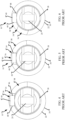
- FIGS. 4-6 are end views of the prior art locking gate in a plurality of rotational positions.
- the pin 20 that the gate 18 pivots about to open and close the locking gate 10 has an enlarged head 40 which slides within the raceway 34 at the second end 30 of the locking collar 22.
- the position of the pin head 40 within the raceway 34 is the third locking configuration and determines if the locking collar 22 is rotatably locked in the triple-locking gate.
- the prior art pin head 40 is cold-formed, and as such, has a substantially cylindrical head wall 46 with a curved surface and is at least partially rounded due to the manufacturing process.
- the raceway 34 is formed from a 1D and/or 2D milling process that results in a plurality of substantially flat surfaces orthogonal to the longitudinal axis 24 (shown in FIG. 1 ).
- the concave surface of the head wall 46 slides across the raceway 34 (e.g. during rotation of the locking collar 22) and stress concentrations are formed at the small contact location area 48 of the head wall 46 against the raceway 34.
- stress concentrations increase wear and corrosion, and create corresponding grooves within the surfaces of the raceway 34. This undesirable wear and corrosion increases friction between the pin head 40 and the locking collar 22 during movement of the locking collar 22 and can prevent the locking gate 10 from properly closing and locking.
- FIGS. 4 and 5 illustrate the pin head 40 within the axial portion 36 of the raceway 34, and thus, the locking collar 22 is rotationally locked.
- FIGS. 2 and 6 illustrate the pin head 40 within the circumferential portion 38 of the raceway 34, and thus, the locking collar 22 is rotationally unlocked.
- the movement of the pin head 40 within the raceway 34 is not always orthogonal to the longitudinal axis 24.
- a contact location 48 of the head wall 46 on the raceway 34 changes during the rotational movement of the locking collar 22.
- the pin head 40 is substantially orthogonal to the surface of the raceway 34 being contacted 48 and the apex of the head wall 46 contacts the raceway 34.
- the surface of the raceway 34 being contacted 48 is located on the outside end of the pin head 40 as shown in FIG. 5 .
- the surface of the raceway 34 being contacted 48 is located on the inside end of the pin head as shown in FIG. 6 .
- the stress concentration location of the pin head 40 on the raceway 34 changes, thereby further increasing undesirable wear that can prevent the locking gate 10 from properly closing and locking.
- the examples of the locking gate described herein and in FIGS. 11-17 use a machined pin head with flat surfaces and a raceway that is 3D milled so that the raceway surface is always tangent to the pin head so as to increase face-on-face contact areas and reduce stress distributions.
- wear is reduced and the reliability of the automatic close and lock functionality and the locking performance of the locking gate over the operational lifetime of the carabiner is increased compared to the prior art locking gate 10.
- FIG. 7 is a side view of an exemplary carabiner 100 in a closed and locked position.
- FIG. 8 is a side view of the carabiner 100 in an open and unlocked position.
- the carabiner 100 includes a body 102 having a nose end 104 and a hinge end 106.
- a locking gate 108 is coupled to the body 102 and includes a gate 110 that is pivotably coupled to the hinge end 106 of the body 102 via a pin 112.
- the gate 110 is pivotable about the pin 112 and is configured to engage with the nose end 104 of the body 102 so as to define a closed position as illustrated in FIG.
- the locking gate 108 also includes a locking collar 114 coupled to the gate 110 and configured to lock the gate 110 in the closed position so as to prevent opening.
- the gate 110 defines a longitudinal axis 116 and the locking collar 114 is rotatable R about the longitudinal axis 116 and translatable T along the longitudinal axis 116 relative to the gate 110.
- the carabiner body 102 has a modified pear-shape with a spine 118 disposed opposite the gate 110. This shape forms a loading area 120 that is positioned away from the locking gate 108 when the locking gate 108 is closed and locked.
- the spine 118 has a spine axis 122 that is disposed at an angle 124 relative to the longitudinal axis 116 of the gate 110. In an example, the angle 124 is between approximately 25° and 55°. In an aspect, the angle 124 is approximately 40°.
- the spine 118 has an inner surface 126 that has a corresponding contour to that of an outer surface 128 of the locking collar 114 and as illustrated in FIG. 8 .
- the amount of unused space between the locking gate 108 and the body 102 is reduced when the carabiner 100 is in the open position (shown in FIG. 8 ).
- This configuration reduces the angle 124 between the locking gate 108 and the spine 118 so as to result in a more compact shape of the carabiner 100 that is easier to use with one hand, while increasing an opening width 130 between the nose end 104 and the locking collar 114 when the carabiner 100 is in the open position.
- this configuration enables the diameter of locking collar 114 to be enlarged so as to meet or exceed cross-loading standards as required or desired.
- the carabiner 100 also includes a swivel loop 132 rotatably coupled to the body 102 so that the swivel loop 132 and the body 102 can rotate 133 relative to one another and about a rotational axis 134.
- a bushing 136 e.g., polymer
- the bushing 136 extends in both an axial direction and a radial direction relative to the rotational axis 134 so that the loop 132 and the body 102 do not slide directly against one another.
- the bushing 136 includes a flange 138 that extends in a radial direction relative to the rotational axis 134, so that when the carabiner 100 is loaded and the loop 132 and the body 102 are being pulled in opposite directions, the bushing 136 is disposed within the loading path and wear is reduced. As such, performance of the carabiner 100 is increased.
- an intersection point 140 of the longitudinal axis 116 of the gate 110 and the spine axis 122 is disposed along the rotational axis 134 and within the connection between the swivel loop 132 and the body 102. This configuration also results in a more compact shape of the carabiner 100 and increases the performance strength of the carabiner 100.
- a captive eye 142 is completely formed within the spine 118 and disposed proximate the swivel loop 132.
- the captive eye 142 and the locking gate 108 are both on the carabiner body 102 so that they can rotate 133 together about the rotational axis 134 and with respect to the swivel loop 132. This configuration enables a secondary gated attachment to be used with the carabiner 100 without defeating the swivel loop 132 as required or desired.
- the swivel loop 132 is attached to the auto-belay line (not shown) and the carabiner body 102 is attached to the climber (e.g., via a harness) with the locking gate 108 being able to reverse this attachment as required.
- the climber can then twist around without inducing a corresponding twist into the auto-belay line (e.g., via the swivel loop 132).
- a secondary tether may be coupled to the captive eye 142 at one end, and the other end can have the secondary gated attachment (e.g., a carabiner) that also attaches to the climber.
- the secondary gated attachment forms a backup/redundant connection system because there have been cases where a connection is made to a wrong loop of a harness and there have been cases where the locking gate unintentionally opens due to rubbing against equipment and/or the wall. Additionally, since the secondary gated attachment is coupled to the carabiner body 102, the climber can still twist around without inducing a corresponding twist into the auto-belay line.
- the captive eye 142 is positioned along the spine axis 122 and is a fixed opening within the carabiner body 102 that is load rated.
- the captive eye 142 is sized and shaped to receive the tether.
- the tether is typically a load bearing webbing or robe.
- the captive eye 142 has a length along the spine axis 122 that corresponds to the width of the tether.
- the captive eye 142 is sized and shaped so that another carabiner cannot be attached to the captive eye 142 and its nose cannot fit through the eye opening. Thereby, allowing for only the secondary attachment tether to be utilized.
- the locking gate 108 is a triple-locking gate, and as such, to unlock the locking collar 114, it must be both translated T and rotated R so as to enable the gate 110 to open.
- the locking gate 108 may be a double-locking gate, and as such, to unlock the locking collar 114, it must be rotated R so as to enable the gate 110 to open.
- the gate 110 is pivotable between an open position as illustrated in FIG. 8 and a closed position as illustrated in FIG. 7 . In the closed position, the gate 110 engages with the nose end 104 of the body 102. The position of the gate 110 defines a first lock configuration for both triple- and double-locking carabiners.
- the locking collar 114 In order to open and close the gate 110, the locking collar 114 must be rotated R between a first rotation position as illustrated in FIG. 7 that locks the locking gate 108 to the body 102 and a second rotation position as illustrated in FIG. 8 that unlocks the locking gate 108 from the body 102.
- the rotational position of the locking collar 114 defines a second lock configuration for both triple- and double-locking carabiners.
- the second lock configuration is described further below in reference to FIGS. 9 and 10 .
- the locking collar 114 In addition to rotating R the locking collar 114, the locking collar 114 must also be translated T between a first translation position as illustrated in FIG. 7 that locks the rotational movement of the locking collar 114 and a second translational position as illustrated in FIG. 8 that unlocks the rotational movement of the locking collar 114.
- the translational position of the locking collar 114 defines a third lock configuration for the triple-locking carabiners.
- the third lock configuration is described further below in reference to FIGS. 11-17 .
- the locking gate 108 is biased so as to automatically return to a closed and locked position. That is, the gate 110 is biased towards the closed position, while the locking collar 114 is biased towards the second rotation position and the second translation position. As such, to open and unlock the locking gate 108, the user must manually overcome the biased positions of the gate 110 and the locking collar 114.
- one or more springs may be housed within the locking collar 114 so as to provide the biasing mechanism for automatically locking and closing the locking gate 108.
- FIG. 9 is an outside view of the locking gate 108 in an intermediate position.
- the locking collar 114 is rotated R about the longitudinal axis 116 and relative to the gate 110. While the locking collar 114 is shown as rotating R clockwise to unlock the locking gate 108, it is appreciated that alternatively, the locking collar 114 may rotate counter-clockwise towards the unlocked position as required or desired.
- the locking collar 114 includes a first end 144 having a first opening 146 and an opposite second end 148 having a second opening 150.
- the locking collar 114 unlocks the gate 110 when both the first opening 146 clears the nose end 104 and the second opening 150 clears the hinge end 106.
- the first opening 146 has a first circumferential length L 3 that is greater than the thickness T 1 of the nose end 104.
- the circumferential length L 3 is greater than the prior art length L 1 of the first opening 28 (shown in FIG. 1 ).
- the length L 3 is more than 10% greater than the length L 1 .
- the length L 3 is more than 20% greater than the length L 1 .
- the length L 3 is between about 5% and 30% greater than the length L 1 .
- the second opening 150 has a second circumferential length L 4 that is about equal to the thickness T 2 of the hinge end 106.
- the thickness T 1 of the nose end 104 is about equal to the thickness T 2 of the hinge end 106.
- the first circumferential length L 3 of the first opening 146 is greater than the second circumferential length L 4 of the second opening 150.
- the first opening 146 is circumferentially offset from the second opening 150. That is, the first opening 146 has a first centerline 158 that is aligned with the longitudinal axis 116 in FIG. 9 and the second opening 150 has a second centerline 160 that is circumferentially offset 162 from the first centerline 158.
- the centerlines 158, 160 of each of the openings 146, 150 are circumferentially offset 162 on the locking collar 114 between approximately 5° and 30°.
- the offset 162 configuration of the first opening 146 and the second opening 150 results in the first opening 146 clearing the nose end 104 before the second opening 150 clears the hinge end 106 upon rotation R of the locking collar 114 towards the unlocked position.
- This intermediate position of the locking collar 114 is illustrated in FIG. 9 .
- a first sidewall 164 of the second opening 150 still covers the hinge end 106 so that the locking collar 114 prevents the gate 110 from opening.
- the intermediate position of the locking collar 114 disables the gate 110 from opening unless the locking collar 114 is manipulated with a full and distinct gate unlocking rotation R movement about the longitudinal axis 116.
- the offset 162 of the openings 146, 150 also reduces or prevents unintentional defeat of the locking gate 108.
- a force vector 166 is generated against the locking gate 108 that induces the locking collar 114 to translate, rotate, and/or depress the locking gate 108.
- a bind is created between the second end 148 of the locking collar 114 and the hinge end 106. This bind prevents the locking gate from completely unlocking and allowing the gate 110 to open with a single motion. Instead, to unlock the locking collar 114 requires a full and distinct unlocking motion. The bind also increases as the force trying to opening locking gate 108 is increased.
- a bind is also created, thereby preventing the locking gate from completely unlocking and allowing the gate 110 to open.
- the bind location is between an inside surface of the locking collar 114 and an outside surface of the hinge end 106.
- FIG. 10 is an outside view of the locking gate 108 in an unlocked position. Certain components are described above, and thus, are not necessarily described further.
- the first opening 146 remains clear of the nose end 104 and the second opening 150 clears the hinge end 106.
- the locking collar 114 is unlocked and disengaged from the carabiner body 102 so that the gate 110 may be opened. Said another way, the second opening 150 clears the hinge end 106 after the first opening 146 clears the nose end 104 so as to unlock the locking collar 114.
- the second centerline 160 of the second opening 150 is aligned with the longitudinal axis 116 in FIG. 10 and the first centerline 158 of the first opening 146 is rotated further in the clockwise direction.
- the first sidewall 152 of the first opening 146 is now offset 168 from the nose end 104, while the second sidewall 156 is closer to, but still clear, of the nose end 104, thereby allowing the gate 110 to open.
- the offset 168 of the sidewall 152 from the nose end 104 provides additional space between the first end 144 of the locking collar 114 and the nose end 104 so that when the locking collar 114 automatically rotates back into the locked position (e.g., counter-clockwise), the sidewall 152 does not contact the nose end 104.
- This additional space reduces wear between the locking collar 114 and the carabiner body 102, and thus, increases the reliability of the automatic close and lock functionality and increases locking performance of the locking gate 108 over the operational lifetime of the carabiner.
- FIG. 11 is a partial side view of the locking gate 108 in a rotational lock position.
- FIG. 12 is an end view of the locking gate 108 in the rotational lock position.
- the second end 148 of the locking collar 114 includes a raceway 170 having both an axial portion 172 and a circumferential portion 174 that are coupled in communication together.
- the axial portion 172 extends along the longitudinal axis 116.
- the pin 112 includes an enlarged head 176 that is slidably received within the raceway 170.
- the pin 112 pivotably couples the gate 110 to the hinge end 106 of the body 102.
- the position of the pin head 176 within the raceway 170 determines if the locking collar 114 is allowed to rotate and unlock the locking gate 108 as described above in reference to FIGS. 9 and 10 .
- the pin head 176 and raceway 170 features may not be included. As illustrated in FIGS. 11 and 12 , the pin head 176 is received within the axial portion 172 of the raceway 170 such that rotation of the locking collar 114 is prevented.
- the pin head 176 is machined formed so that it has a substantially flat and parallel cylindrical head wall 178. That is the pin head 176 is a right angle cylindrical component.
- the raceway 170 is formed from a 3D milling process with surfaces that are substantially flat and parallel to the movement of the pin head 176 with all approach angles accounted for during the locking collar's 114 rotation. As such, the surfaces of the raceway 170 are not necessary parallel and/or orthogonal to the longitudinal axis 116, because 3D milling allows the mill to be moved relative to the locking collar 114 just as the pin head 176 moves during operation of the locking gate 108.
- tangent means that the surfaces of the raceway 170 are orthogonal to a diameter line of the pin head 176 going through a center point of the pin head and within ⁇ 10° from orthogonal. In an aspect, tangent can be ⁇ 5° from orthogonal.
- the thickness of the raceway 170 is greater than or equal to the thickness of the pin head 176 so that the majority of the pin head 176 is in face-on-face contact with the raceway 170 to further reduce stress concentrations.
- the head wall 178 is parallel to the contacting surface of the axial portion 172, and thus, undesirable grooves within the surface of the raceway 170 are less likely to be formed.
- face-on-face contact means that the surface of the raceway 170 is always tangent to the cylindrical head wall 178.
- FIG. 13 is another partial side view of the locking gate 108 in a rotational lock position.
- FIG. 14 is another end view of the locking gate 108 in the rotational lock position.
- the pin head 176 is disposed within the axial portion 172 of the raceway 170, and thus, rotation of the locking collar 114 is prevented. As illustrated in FIGS. 13 and 14 , the pin head 176 is contacting a different surface of the raceway 170, but the surface is still tangent to the cylindrical head wall 178 so as to have face-on-face contact and reduce stress distributions.
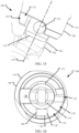
- FIG. 15 is a partial side view of the locking gate 108 in a rotational unlock position.
- FIG. 16 is an end view of the locking gate 108 in the rotational unlock position.
- FIG. 17 is a partial perspective view of the locking gate 108 in the rotational unlock position.
- the locking collar 114 is translatable T along the longitudinal axis 116 relative to the gate 110. In order to enable rotation of the locking collar 114, the locking collar 114 is translated so that the pin head 176 slides out of the axial portion 172 of the raceway 170, which restricts rotation, and into the circumferential portion 174 of the raceway 170, which allows rotation.
- the locking collar 114 has been both translated and rotated so as to unlock the locking gate 108 and the gate 110 can be opened as required or desired.
- the pin head 176 is contacting yet another surface of the raceway 170, but the surface is still tangent to the cylindrical head wall 178 so as to have face-on-face contact and reduce stress distributions.
Landscapes
- Engineering & Computer Science (AREA)
- General Engineering & Computer Science (AREA)
- Mechanical Engineering (AREA)
- Hooks, Suction Cups, And Attachment By Adhesive Means (AREA)
Description
- This application is being filed on November 4, 2020, as a PCT International Application, and claims priority to and the benefit of
U.S. Provisional Application No. 62/989,401, filed March 13, 2020 U.S. Provisional Application No. 62/930,779, filed November 5, 2019 - Generally, carabiners include a metal loop having a spring-loaded gate and they are widely used in cable and rope intensive activates for quickly and reversibly connecting two or more components. These activities include, but are not limited to, rock and mountain climbing (e.g., indoor or outdoor climbing), zip lining, arboriculture, caving, sailing, hot air ballooning, rope rescue, construction, industrial rope work, window cleaning, whitewater rescue, acrobatics, etc. At least some known carabiners include locking gates to secure the carabiner gate against unintentional opening during use. Some known locking carabiners are automatic twist/push-locking that have a security sleeve over the gate that must be manually rotated and/or pulled to disengage so as to unlock and enable operation of the gate. However, these known twist/push-locking carabiners may be unintentionally defeated by the carabiner rubbing against the rope or equipment in a motion that rotates and/or pulls the security sleeve in a direction that unlocks and opens the gate.
- Additionally, some cable and rope intensive activities generate a high number of locking-unlocking cycles on the carabiner over a relatively short time period. For example, line dispensing devices, such as auto-belay devices used for climbing, retract slack when the rope is not under load (e.g., when the climber is climbing) and provides a braking force when the rope is loaded (e.g., when the climber falls) so that the climber on the end of the rope is lowered to the ground. These systems allow climbers to climb alone and eliminate the need for a separate belayer, and as such, the carabiner that attaches the user to the auto-belay device can be opened and closed many times during climbing sessions. Repetitive locking and unlocking of the gate induces wear on the security sleeve, which over time, reduces the locking and closing functionality of the carabiner.
- An example of snap hook is disclosed in document
US 2010/0325848 A1 , which describes a snap hook having a body, a pivotal gate, and a rotatable locking member mounted on the pivotal gate. The locking member includes a slot on one end and a passage on the other end. Rotating the locking member aligns the slot and the passage with the body simultaneously to move the locking member into an unlocking position. - This disclosure describes examples of an automatic locking swivel carabiner. The locking mechanisms for a carabiner gate are enabled to reduce wear, thereby increasing performance of the locking mechanism and extending the life of the carabiner. Additionally, the locking mechanism reduces or prevents unintentional defeat because a bind is created between a locking collar and a carabiner body that requires a full and distinct motion to unlock the locking collar before opening the carabiner. Furthermore, the carabiner describe herein enables for secondary gated attachments to be used without defeating the swivel capabilities of the carabiner.
- These and various other features as well as advantages that characterize the carabiners described herein will be apparent from a reading of the following detailed description and a review of the associated drawings. Additional features are set forth in the description which follows, and in part will be apparent from the description, or may be learned by practice of the technology. The benefits and features of the technology will be realized and attained by the structure particularly pointed out in the written description and claims hereof as well as the appended drawings.
- It is to be understood that both the foregoing introduction and the following detailed description are exemplary and explanatory and are intended to provide further explanation of the invention as claimed.
- The following drawing figures, which form a part of this application, are illustrative of described technology and are not mean to limit the scope of the invention as claimed in any manner, which scope shall be based on the claims appended hereto.
-
FIG. 1 is a side view of a prior art locking gate in an unlocked and closed position. -
FIG. 2 is a partial enlarged view of the prior art locking gate in the unlocked position. -
FIG. 3 is a schematic view of the prior art locking gate. -
FIG. 4 is an end view of the prior art locking gate in a rotational lock position. -
FIG. 5 is another end view of the prior art locking gate in the rotational lock position. -
FIG. 6 is an end view of the prior art locking gate in a rotational unlock position. -
FIG. 7 is a side view of an exemplary carabiner in a closed and locked position. -
FIG. 8 is a side view of the carabiner in an open and unlocked position. -
FIG. 9 is a side view of a locking gate of the carabiner in an intermediate and closed position. -
FIG. 10 is a side view of the locking gate in an unlocked and closed position. -
FIG. 11 is a partial side view of the locking gate in a rotational lock position. -
FIG. 12 is an end view of the locking gate in the rotational lock position. -
FIG. 13 is another partial side view of the locking gate in the rotational lock position. -
FIG. 14 is another end view of the locking gate in the rotational lock position. -
FIG. 15 is a partial side view of the locking gate in a rotational unlock position. -
FIG. 16 is an end view of the locking gate in the rotational unlock position. -
FIG. 17 is a partial perspective view of the locking gate in the rotational unlock position. - This disclosure describes examples of a triple-locking swivel carabiner, although the features of the swivel carabiner can also be used in double-locking carabiners as required or desired. The carabiners described herein have a gate that is pivotably coupled to a body and extending between a hinge end and a nose end. The gate can pivot relative to the hinge end so as to open and close the carabiner with respect to the nose end. A locking collar is coupled to the gate, such that the gate can be automatically locked relative to the body when the gate is in the closed position. This locking feature reduces unintentional opening of the gate during use.
- In both a triple-locking gate and a double-locking gate, the locking collar is rotatable relative to the gate. The rotational position of the locking collar engages and disengages the locking collar from the carabiner body so as to lock and unlock the gate for opening and closing. In the examples described herein, the locking collar has openings proximate the nose end and the hinge end that must clear the carabiner body so as to unlock the gate. The nose end opening is at least circumferentially offset from the hinge end opening on the locking collar, thereby requiring that the nose end opening clears the carabiner body prior to the hinge end opening. By offsetting these two openings, unintentional defeat of the locking collar is reduced or prevented because a bind is created between the locking collar and the carabiner body that requires a full and distinct rotation motion to unlock the locking collar. Additionally, the size of the nose end opening is lengthened. By increasing the size of the nose end opening and offsetting the two openings, wear on the carabiner's locking mechanism is reduced, thereby increasing performance of the locking mechanism and extending the life of the carabiner.
- In a triple-locking gate, the locking collar is also translatable relative to the gate so that the locking collar has to be moved out of a rotational locking position prior to unlocking the gate. This rotational lock is enabled by a pin slidably received within a raceway at an end of the locking collar and requires translation of the locking collar to rotationally unlock the locking collar. In the examples described herein, the pin is machined and the raceway is 3D milled so that the raceway is always tangent to the pin as the pin slides thereon. This configuration increases face-on-face contact area between the pin and the raceway to reduce stress concentrations. As such, additional wear on the carabiner's locking mechanism is reduced, thereby increasing performance of the locking mechanism and extending the life of the carabiner.
- Furthermore in the carabiners described herein, the carabiner body also includes a spine having a captive eye for receiving a secondary gated attachment. The captive eye swivels with the carabiner body so that the secondary gated attachment can be used without defeating the swivel capabilities of the carabiner. The spine also can at least partially contour to the locking collar so that when the locking gate is open, the opening width is enlarged while maintaining an overall compact design of the carabiner.
- As used herein, the terms "axial" and "longitudinal" refer to directions and orientations, which extend substantially parallel to a centerline of the locking gate. Moreover, the terms "radial" and "radially" refer to directions and orientations, which extend substantially perpendicular to the centerline of the locking gate. In addition, as used herein, the term "circumferential" and "circumferentially" refer to directions and orientations, which extend arcuately about the centerline of the locking gate.
-
FIG. 1 is a side view of a priorart locking gate 10 in an unlocked position and closed position.FIG. 2 is a partial enlarged view of the priorart locking gate 10 in the unlocked position. Referring concurrently toFIGS. 1 and2 , the lockinggate 10 is pivotably coupled to acarabiner body 12, although thecarabiner body 12 is not illustrated inFIG. 2 for clarity. Thebody 12 includes anose end 14 and ahinge end 16. The lockinggate 10 includes agate 18 that is pivotably coupled to thehinge end 16 of thebody 12 via apin 20. Thegate 18 is configured to engage with the nose end 14 of the body so as to define a closed position and that is illustrated inFIG. 1 . The lockinggate 10 also includes alocking collar 22 coupled to thegate 18 and configured to lock thegate 18 in the closed position. Thegate 18 defines alongitudinal axis 24 and the lockingcollar 22 is rotatable R about thelongitudinal axis 24 and translatable T along thelongitudinal axis 24 relative to thegate 18. - The locking
collar 22 includes afirst end 26 having afirst opening 28 and an oppositesecond end 30 having asecond opening 32. Thefirst opening 28 has a first circumferential length L1 that is about equal to the thickness T1 of thenose end 14 and thesecond opening 32 has a second circumferential length L2 that is about equal to the thickness T2 of thehinge end 16. In the prior art, the thicknesses T1 and T2 of thenose end 14 and thehinge end 16 are about equal so that the first circumferential length L1 is about equal to the second circumferential length L2. As such, when the lockingcollar 22 rotates towards the unlocked position, thefirst opening 28 aligns with thenose end 14 substantially simultaneously with thesecond opening 32 aligning with thehinge end 16. Once the lockingcollar 22 clears thenose end 14 and thehinge end 16 of thecarabiner body 12, the lockingcollar 22 is unlocked as illustrated inFIG. 1 so that thegate 18 is enabled to pivot about thepin 20 and move towards an open position. Additionally in the prior art, the axial centerlines of thefirst opening 28 and thesecond opening 32 are aligned on thelocking collar 22. That is, the axial centerlines of theopenings longitudinal axis 24 as illustrated inFIG. 1 , and as such, upon rotation R of the lockingcollar 22 bothopenings body 12 at the same time to unlock the lockinggate 10. - The
second end 30 of the lockingcollar 22 also includes araceway 34 having both anaxial portion 36 and acircumferential portion 38 that are coupled in communication together. Thepin 20 includes anenlarged head 40 that is slidably received within theraceway 34. When thepin head 40 is within theaxial portion 36 of theraceway 34, rotation R of the lockingcollar 22 is prevented, however, upon translation T of the lockingcollar 22, thepin head 40 is moved within thecircumferential portion 38 so that the lockingcollar 22 can rotate R and unlock the lockinggate 10.FIG. 2 illustrates thepin head 40 being within thecircumferential portion 38 of theraceway 34, and thus, rotation R of the lockingcollar 22 is enabled. - In the example, the prior
art locking gate 10 is considered triple-locking with a first lock configuration being thegate 18 engaging with the nose end 14 of thebody 12, a second lock configuration being the lockingcollar 22 rotated R such that it is engaged with thebody 12 and thegate 18 is prevented from moving towards the open position, and a third lock configuration being the lockingcollar 22 translated T so that thepin head 40 is received within theaxial portion 36 of theraceway 34 and the lockingcollar 22 is rotationally locked. The lockinggate 10 is biased so as to automatically return to a fully locked positioned and all three lock configurations are engaged. As such, to unlock the lockinggate 10, the lockingcollar 22 is first translated T along thelongitudinal axis 24 so that thepin head 40 is moved from theaxial portion 36 to thecircumferential portion 38 of theraceway 34. This position of thepin head 40 enables the lockingcollar 22 to then rotate R about thelongitudinal axis 24 so as to align theopenings nose end 14 and thehinge end 16, respectively, and unlock thegate 18. Once unlocked, thegate 18 can pivot into the open position. This priorart locking gate 10, however, has some functional disadvantages that are described further below in reference toFIGS. 3-6 . - It is appreciated that while a triple-locking
gate 10 is illustrated and described, the lockinggate 10 may alternatively be a double-lockinggate 10, whereby the lockingcollar 22 is only rotatable R about thelongitudinal axis 24 so as to lock thegate 18 in the closed position. In the double-locking gate example, the lockingcollar 22 is not necessarily translatable along thelongitudinal axis 24. - As used herein, a closed position is when the
gate 18 is engaged with the nose end 14 of thecarabiner body 12 and an open position is when thegate 18 is pivoted inward relative to thebody 12 so that thenose end 14 can receive various equipment components. The closed position is illustrated inFIG. 1 . Additionally, a locked position is when the lockingcollar 22 is engaged with thecarabiner body 12 so as to secure thegate 18 in the closed position and an unlocked position is when the lockingcollar 22 is disengaged with thecarabiner body 12 such that thegate 18 is enabled to be moved towards the open position. The locked position may include two locking configurations (e.g., the second and third configurations described above) for a triple-locking gate or include one locking configuration (e.g., the second configuration described above) for a double-locking gate. The unlocked position is illustrated inFIGS. 1 and2 . -
FIG. 3 is a schematic view of the priorart locking gate 10. Certain components are described above, and thus, are not necessarily described further. As described above, to unlock the lockinggate 10, the lockingcollar 22 must be both translated along thelongitudinal axis 24 and rotated about thelongitudinal axis 24. Then once the lockingcollar 22 clears both thenose end 14 and thehinge end 16, thegate 18 is allowed to pivot into the open position. Unlocking the lockinggate 10, generally requires manual manipulation of the lockinggate 10 by the user, however, the lockinggate 10 may be unintentionally defeated by rubbing against other equipment and/or the climbing surfaces in such a way that aforce vector 42 is generated against the lockinggate 10. Theforce vector 42 is generated in such an orientation and against the lockingcollar 22 that results in thelocking collar 22 translating, rotating, and depressing the lockinggate 10 in a single motion so as to undesirably unlock and open the lockinggate 10. In double-locking gates, unintentional defeat is also an issue with theforce vector 42 that results in rotating the lockingcollar 22 and depressing the locking gate in a single motion so as to undesirably unlock and open the lockinggate 10. - The examples of the locking gate described herein and in
FIGS. 9 and10 , reduces or prevents this unintentional defeat of the locking gate from theforce vector 42. The openings on the locking collar are circumferentially offset so that the first opening clears the body prior to the second opening. As such, an intermediate position is formed that creates a bind between the locking collar and the body. This bind prevents the locking gate from completely unlocking and allowing the gate to open. As such, two or three (depending on the double- or triple-locking configuration) full and distinct gate unlocking motions are required to unlock the locking gate, and the force vector does not defeat the locking gate unlike the priorart locking gate 10. - Additionally, the prior
art locking gate 10 has itslocking collar 22 with thefirst opening 28 that substantially matches the size of thenose end 14. Because of the dimension of thefirst opening 28, when the lockinggate 10 is in the open position and moves toward the close and lock positions, the lockingcollar 22 begins to rotate during closure pivoting of thegate 18, and thereby, contacts thenose end 14 when automatically returning to the closed and locked position. Thus, asidewall 44 of theopening 28 slides and scrapes against and the nose end 14 of thecarabiner body 12 during use. Thesidewall 44 that wears could be on either side of theopening 28, depending on the rotation direction of the lockingcollar 22. The contact between the lockingcollar 22 and thebody 12 increases undesirable wear and corrosion on the lockinggate 10 and creates sharp edges between the contacting components that increases friction and can prevent the lockinggate 10 from properly closing and locking. - The examples of the locking gate described herein and in
FIGS. 9 and10 , reduces wear between the locking collar and the carabiner body. The nose end opening is enlarged and offset from the hinge end opening so that during the locking rotation of the locking collar, the locking collar does not come into contact with the nose end. Thus, wear is reduced and the reliability of the automatic close and lock functionality and the locking performance of the locking gate over the operational lifetime of the carabiner is increased compared to the priorart locking gate 10. -
FIGS. 4-6 are end views of the prior art locking gate in a plurality of rotational positions. Referring concurrently toFIGS. 4-6 and with continued reference toFIG. 2 , certain components are described above, and thus, are not necessarily described further. As described above, thepin 20 that thegate 18 pivots about to open and close the lockinggate 10 has anenlarged head 40 which slides within theraceway 34 at thesecond end 30 of the lockingcollar 22. The position of thepin head 40 within theraceway 34 is the third locking configuration and determines if the lockingcollar 22 is rotatably locked in the triple-locking gate. The priorart pin head 40 is cold-formed, and as such, has a substantiallycylindrical head wall 46 with a curved surface and is at least partially rounded due to the manufacturing process. Additionally, theraceway 34 is formed from a 1D and/or 2D milling process that results in a plurality of substantially flat surfaces orthogonal to the longitudinal axis 24 (shown inFIG. 1 ). - In operation, however, the concave surface of the
head wall 46 slides across the raceway 34 (e.g. during rotation of the locking collar 22) and stress concentrations are formed at the smallcontact location area 48 of thehead wall 46 against theraceway 34. These stress concentrations increase wear and corrosion, and create corresponding grooves within the surfaces of theraceway 34. This undesirable wear and corrosion increases friction between thepin head 40 and the lockingcollar 22 during movement of the lockingcollar 22 and can prevent the lockinggate 10 from properly closing and locking. -
FIGS. 4 and 5 illustrate thepin head 40 within theaxial portion 36 of theraceway 34, and thus, the lockingcollar 22 is rotationally locked.FIGS. 2 and6 illustrate thepin head 40 within thecircumferential portion 38 of theraceway 34, and thus, the lockingcollar 22 is rotationally unlocked. - Additionally, the movement of the
pin head 40 within theraceway 34 is not always orthogonal to thelongitudinal axis 24. As such, because of the 1D and/or 2D milling process of the raceway, acontact location 48 of thehead wall 46 on theraceway 34 changes during the rotational movement of the lockingcollar 22. For example, inFIGS. 2 and4 thepin head 40 is substantially orthogonal to the surface of theraceway 34 being contacted 48 and the apex of thehead wall 46 contacts theraceway 34. In other rotation positions of the lockingcollar 22, the surface of theraceway 34 being contacted 48 is located on the outside end of thepin head 40 as shown inFIG. 5 . In still other rotational positions of the lockingcollar 22, the surface of theraceway 34 being contacted 48 is located on the inside end of the pin head as shown inFIG. 6 . As such, the stress concentration location of thepin head 40 on theraceway 34 changes, thereby further increasing undesirable wear that can prevent the lockinggate 10 from properly closing and locking. - The examples of the locking gate described herein and in
FIGS. 11-17 use a machined pin head with flat surfaces and a raceway that is 3D milled so that the raceway surface is always tangent to the pin head so as to increase face-on-face contact areas and reduce stress distributions. Thus, wear is reduced and the reliability of the automatic close and lock functionality and the locking performance of the locking gate over the operational lifetime of the carabiner is increased compared to the priorart locking gate 10. -
FIG. 7 is a side view of anexemplary carabiner 100 in a closed and locked position.FIG. 8 is a side view of thecarabiner 100 in an open and unlocked position. Referring concurrently toFIGS. 7 and8 , thecarabiner 100 includes abody 102 having anose end 104 and ahinge end 106. A lockinggate 108 is coupled to thebody 102 and includes agate 110 that is pivotably coupled to thehinge end 106 of thebody 102 via apin 112. Thegate 110 is pivotable about thepin 112 and is configured to engage with thenose end 104 of thebody 102 so as to define a closed position as illustrated inFIG. 7 and disengage with thenose end 104 of thebody 102 so as to define an open position as illustrated inFIG. 8 . The lockinggate 108 also includes alocking collar 114 coupled to thegate 110 and configured to lock thegate 110 in the closed position so as to prevent opening. Thegate 110 defines alongitudinal axis 116 and thelocking collar 114 is rotatable R about thelongitudinal axis 116 and translatable T along thelongitudinal axis 116 relative to thegate 110. - The
carabiner body 102 has a modified pear-shape with aspine 118 disposed opposite thegate 110. This shape forms aloading area 120 that is positioned away from the lockinggate 108 when the lockinggate 108 is closed and locked. Thespine 118 has aspine axis 122 that is disposed at anangle 124 relative to thelongitudinal axis 116 of thegate 110. In an example, theangle 124 is between approximately 25° and 55°. In an aspect, theangle 124 is approximately 40°. Thespine 118 has aninner surface 126 that has a corresponding contour to that of anouter surface 128 of thelocking collar 114 and as illustrated inFIG. 8 . By contouring theinner surface 126 geometry of thespine 118 with theouter surface 128 geometry of thelocking collar 114, or by contouring theouter surface 128 geometry of thelocking collar 114 with theinner surface 126 geometry of thespine 118, the amount of unused space between the lockinggate 108 and thebody 102 is reduced when thecarabiner 100 is in the open position (shown inFIG. 8 ). This configuration reduces theangle 124 between the lockinggate 108 and thespine 118 so as to result in a more compact shape of thecarabiner 100 that is easier to use with one hand, while increasing anopening width 130 between thenose end 104 and thelocking collar 114 when thecarabiner 100 is in the open position. Furthermore, this configuration enables the diameter of lockingcollar 114 to be enlarged so as to meet or exceed cross-loading standards as required or desired. - The
carabiner 100 also includes aswivel loop 132 rotatably coupled to thebody 102 so that theswivel loop 132 and thebody 102 can rotate 133 relative to one another and about a rotational axis 134. A bushing 136 (e.g., polymer) is disposed between theswivel loop 132 and thebody 102. Thebushing 136 extends in both an axial direction and a radial direction relative to the rotational axis 134 so that theloop 132 and thebody 102 do not slide directly against one another. As such, thebushing 136 includes aflange 138 that extends in a radial direction relative to the rotational axis 134, so that when thecarabiner 100 is loaded and theloop 132 and thebody 102 are being pulled in opposite directions, thebushing 136 is disposed within the loading path and wear is reduced. As such, performance of thecarabiner 100 is increased. In the example, an intersection point 140 of thelongitudinal axis 116 of thegate 110 and thespine axis 122 is disposed along the rotational axis 134 and within the connection between theswivel loop 132 and thebody 102. This configuration also results in a more compact shape of thecarabiner 100 and increases the performance strength of thecarabiner 100. - A
captive eye 142 is completely formed within thespine 118 and disposed proximate theswivel loop 132. Thecaptive eye 142 and the lockinggate 108 are both on thecarabiner body 102 so that they can rotate 133 together about the rotational axis 134 and with respect to theswivel loop 132. This configuration enables a secondary gated attachment to be used with thecarabiner 100 without defeating theswivel loop 132 as required or desired. - For example, when the
carabiner 100 is used for auto-belay activities, theswivel loop 132 is attached to the auto-belay line (not shown) and thecarabiner body 102 is attached to the climber (e.g., via a harness) with the lockinggate 108 being able to reverse this attachment as required. The climber can then twist around without inducing a corresponding twist into the auto-belay line (e.g., via the swivel loop 132). A secondary tether (not shown) may be coupled to thecaptive eye 142 at one end, and the other end can have the secondary gated attachment (e.g., a carabiner) that also attaches to the climber. The secondary gated attachment forms a backup/redundant connection system because there have been cases where a connection is made to a wrong loop of a harness and there have been cases where the locking gate unintentionally opens due to rubbing against equipment and/or the wall. Additionally, since the secondary gated attachment is coupled to thecarabiner body 102, the climber can still twist around without inducing a corresponding twist into the auto-belay line. In the example, thecaptive eye 142 is positioned along thespine axis 122 and is a fixed opening within thecarabiner body 102 that is load rated. - In the example, the
captive eye 142 is sized and shaped to receive the tether. The tether is typically a load bearing webbing or robe. In an aspect, thecaptive eye 142 has a length along thespine axis 122 that corresponds to the width of the tether. In another aspect, thecaptive eye 142 is sized and shaped so that another carabiner cannot be attached to thecaptive eye 142 and its nose cannot fit through the eye opening. Thereby, allowing for only the secondary attachment tether to be utilized. - In the example, the locking
gate 108 is a triple-locking gate, and as such, to unlock thelocking collar 114, it must be both translated T and rotated R so as to enable thegate 110 to open. In other examples, the lockinggate 108 may be a double-locking gate, and as such, to unlock thelocking collar 114, it must be rotated R so as to enable thegate 110 to open. In both examples, thegate 110 is pivotable between an open position as illustrated inFIG. 8 and a closed position as illustrated inFIG. 7 . In the closed position, thegate 110 engages with thenose end 104 of thebody 102. The position of thegate 110 defines a first lock configuration for both triple- and double-locking carabiners. In order to open and close thegate 110, thelocking collar 114 must be rotated R between a first rotation position as illustrated inFIG. 7 that locks the lockinggate 108 to thebody 102 and a second rotation position as illustrated inFIG. 8 that unlocks the lockinggate 108 from thebody 102. The rotational position of thelocking collar 114 defines a second lock configuration for both triple- and double-locking carabiners. The second lock configuration is described further below in reference toFIGS. 9 and10 . - For triple-locking carabiners, in addition to rotating R the
locking collar 114, thelocking collar 114 must also be translated T between a first translation position as illustrated inFIG. 7 that locks the rotational movement of thelocking collar 114 and a second translational position as illustrated inFIG. 8 that unlocks the rotational movement of thelocking collar 114. The translational position of thelocking collar 114 defines a third lock configuration for the triple-locking carabiners. The third lock configuration is described further below in reference toFIGS. 11-17 . - In both the triple- and double-locking carabiner examples, the locking
gate 108, including both thegate 110 and thelocking collar 114, is biased so as to automatically return to a closed and locked position. That is, thegate 110 is biased towards the closed position, while thelocking collar 114 is biased towards the second rotation position and the second translation position. As such, to open and unlock the lockinggate 108, the user must manually overcome the biased positions of thegate 110 and thelocking collar 114. For example, one or more springs (not shown) may be housed within thelocking collar 114 so as to provide the biasing mechanism for automatically locking and closing the lockinggate 108. -
FIG. 9 is an outside view of the lockinggate 108 in an intermediate position. As described above, to move thelocking collar 114 into an unlocked position and allow thegate 110 to open relative to thecarabiner body 102, thelocking collar 114 is rotated R about thelongitudinal axis 116 and relative to thegate 110. While thelocking collar 114 is shown as rotating R clockwise to unlock the lockinggate 108, it is appreciated that alternatively, thelocking collar 114 may rotate counter-clockwise towards the unlocked position as required or desired. - The
locking collar 114 includes afirst end 144 having afirst opening 146 and an oppositesecond end 148 having asecond opening 150. Thelocking collar 114 unlocks thegate 110 when both thefirst opening 146 clears thenose end 104 and thesecond opening 150 clears thehinge end 106. In the example, thefirst opening 146 has a first circumferential length L3 that is greater than the thickness T1 of thenose end 104. As such, the circumferential length L3 is greater than the prior art length L1 of the first opening 28 (shown inFIG. 1 ). In an aspect, the length L3 is more than 10% greater than the length L1. In another aspect, the length L3 is more than 20% greater than the length L1. In still another aspect, the length L3 is between about 5% and 30% greater than the length L1. By enlarging the circumferential length L3 of thefirst opening 146, when thelocking collar 114 rotates, afirst sidewall 152 of theopening 146 clears thenose end 104 while an offset 154 is formed between asecond sidewall 156 and thenose end 104. - The
second opening 150 has a second circumferential length L4 that is about equal to the thickness T2 of thehinge end 106. In some examples, the thickness T1 of thenose end 104 is about equal to the thickness T2 of thehinge end 106. As such, the first circumferential length L3 of thefirst opening 146 is greater than the second circumferential length L4 of thesecond opening 150. Unlike the prior art design (shown inFIGS. 1-6 ), thefirst opening 146 is circumferentially offset from thesecond opening 150. That is, thefirst opening 146 has afirst centerline 158 that is aligned with thelongitudinal axis 116 inFIG. 9 and thesecond opening 150 has asecond centerline 160 that is circumferentially offset 162 from thefirst centerline 158. In an example, thecenterlines openings locking collar 114 between approximately 5° and 30°. - In the example, the offset 162 configuration of the
first opening 146 and thesecond opening 150 results in thefirst opening 146 clearing thenose end 104 before thesecond opening 150 clears thehinge end 106 upon rotation R of thelocking collar 114 towards the unlocked position. This intermediate position of thelocking collar 114 is illustrated inFIG. 9 . In the intermediate position, after thefirst sidewall 152 of thefirst opening 146 clears thenose end 104, afirst sidewall 164 of thesecond opening 150 still covers thehinge end 106 so that thelocking collar 114 prevents thegate 110 from opening. The intermediate position of thelocking collar 114 disables thegate 110 from opening unless thelocking collar 114 is manipulated with a full and distinct gate unlocking rotation R movement about thelongitudinal axis 116. - The offset 162 of the
openings gate 108. When the lockinggate 108 rubs against other equipment and/or climbing surfaces and a force vector 166 is generated against the lockinggate 108 that induces thelocking collar 114 to translate, rotate, and/or depress the lockinggate 108. Once the intermediate position is reached, a bind is created between thesecond end 148 of thelocking collar 114 and thehinge end 106. This bind prevents the locking gate from completely unlocking and allowing thegate 110 to open with a single motion. Instead, to unlock thelocking collar 114 requires a full and distinct unlocking motion. The bind also increases as the force trying to openinglocking gate 108 is increased. In double-locking gates, when the force vector 166 rotates and/or depresses the lockinggate 108, a bind is also created, thereby preventing the locking gate from completely unlocking and allowing thegate 110 to open. In the example, the bind location is between an inside surface of thelocking collar 114 and an outside surface of thehinge end 106. -
FIG. 10 is an outside view of the lockinggate 108 in an unlocked position. Certain components are described above, and thus, are not necessarily described further. Upon further rotation R of thelocking collar 114 about thelongitudinal axis 116 from the intermediate position (shown inFIG. 9 ), thefirst opening 146 remains clear of thenose end 104 and thesecond opening 150 clears thehinge end 106. Once both thefirst opening 146 clears thenose end 104 and thesecond opening 150 clears thehinge end 106, thelocking collar 114 is unlocked and disengaged from thecarabiner body 102 so that thegate 110 may be opened. Said another way, thesecond opening 150 clears thehinge end 106 after thefirst opening 146 clears thenose end 104 so as to unlock thelocking collar 114. - In the unlocked position, the
second centerline 160 of thesecond opening 150 is aligned with thelongitudinal axis 116 inFIG. 10 and thefirst centerline 158 of thefirst opening 146 is rotated further in the clockwise direction. In the unlocked position, thefirst sidewall 152 of thefirst opening 146 is now offset 168 from thenose end 104, while thesecond sidewall 156 is closer to, but still clear, of thenose end 104, thereby allowing thegate 110 to open. The offset 168 of thesidewall 152 from thenose end 104 provides additional space between thefirst end 144 of thelocking collar 114 and thenose end 104 so that when thelocking collar 114 automatically rotates back into the locked position (e.g., counter-clockwise), thesidewall 152 does not contact thenose end 104. This additional space reduces wear between the lockingcollar 114 and thecarabiner body 102, and thus, increases the reliability of the automatic close and lock functionality and increases locking performance of the lockinggate 108 over the operational lifetime of the carabiner. -
FIG. 11 is a partial side view of the lockinggate 108 in a rotational lock position.FIG. 12 is an end view of the lockinggate 108 in the rotational lock position. Referring concurrently toFIGS. 11 and 12 , thesecond end 148 of thelocking collar 114 includes araceway 170 having both anaxial portion 172 and acircumferential portion 174 that are coupled in communication together. Theaxial portion 172 extends along thelongitudinal axis 116. Thepin 112 includes anenlarged head 176 that is slidably received within theraceway 170. Thepin 112 pivotably couples thegate 110 to thehinge end 106 of thebody 102. In examples were the lockinggate 108 is triple-locking, the position of thepin head 176 within theraceway 170 determines if thelocking collar 114 is allowed to rotate and unlock the lockinggate 108 as described above in reference toFIGS. 9 and10 . In double-locking gates, thepin head 176 andraceway 170 features may not be included. As illustrated inFIGS. 11 and 12 , thepin head 176 is received within theaxial portion 172 of theraceway 170 such that rotation of thelocking collar 114 is prevented. - In the example, the
pin head 176 is machined formed so that it has a substantially flat and parallelcylindrical head wall 178. That is thepin head 176 is a right angle cylindrical component. Additionally, theraceway 170 is formed from a 3D milling process with surfaces that are substantially flat and parallel to the movement of thepin head 176 with all approach angles accounted for during the locking collar's 114 rotation. As such, the surfaces of theraceway 170 are not necessary parallel and/or orthogonal to thelongitudinal axis 116, because 3D milling allows the mill to be moved relative to thelocking collar 114 just as thepin head 176 moves during operation of the lockinggate 108. By 3D milling theraceway 170, the surfaces of theraceway 170 are always tangent to the fixedpin 112 and thecylindrical head wall 178 as thelocking collar 114 is being rotated relative to thepin 112. This results increasing face-on-face contact area 180 between thehead wall 178 and theraceway 170 at every location and reduces stress concentrations when compared to the prior art shown inFIGS. 4-6 . As used herein, "tangent" means that the surfaces of theraceway 170 are orthogonal to a diameter line of thepin head 176 going through a center point of the pin head and within ± 10° from orthogonal. In an aspect, tangent can be ± 5° from orthogonal. - Additionally, the thickness of the
raceway 170 is greater than or equal to the thickness of thepin head 176 so that the majority of thepin head 176 is in face-on-face contact with theraceway 170 to further reduce stress concentrations. As illustrated inFIG. 12 , thehead wall 178 is parallel to the contacting surface of theaxial portion 172, and thus, undesirable grooves within the surface of theraceway 170 are less likely to be formed. By reducing stress concentrations between thepin 112 and thelocking collar 114, wear is reduced, and thus, increases the reliability of the automatic close and lock functionality and increases locking performance of the lockinggate 108 over the operational lifetime of the carabiner. As used herein, face-on-face contact means that the surface of theraceway 170 is always tangent to thecylindrical head wall 178. -
FIG. 13 is another partial side view of the lockinggate 108 in a rotational lock position.FIG. 14 is another end view of the lockinggate 108 in the rotational lock position. Referring concurrently toFIGS. 13 and 14 , certain components are described above, and thus, are not necessarily described further. Similar toFIGS. 11 and 12 , thepin head 176 is disposed within theaxial portion 172 of theraceway 170, and thus, rotation of thelocking collar 114 is prevented. As illustrated inFIGS. 13 and 14 , thepin head 176 is contacting a different surface of theraceway 170, but the surface is still tangent to thecylindrical head wall 178 so as to have face-on-face contact and reduce stress distributions. -
FIG. 15 is a partial side view of the lockinggate 108 in a rotational unlock position.FIG. 16 is an end view of the lockinggate 108 in the rotational unlock position.FIG. 17 is a partial perspective view of the lockinggate 108 in the rotational unlock position. Referring concurrently toFIGS. 15-17 , certain components are described above, and thus, are not necessarily described further. As described above, thelocking collar 114 is translatable T along thelongitudinal axis 116 relative to thegate 110. In order to enable rotation of thelocking collar 114, thelocking collar 114 is translated so that thepin head 176 slides out of theaxial portion 172 of theraceway 170, which restricts rotation, and into thecircumferential portion 174 of theraceway 170, which allows rotation. As illustrated inFIGS. 15-17 , thelocking collar 114 has been both translated and rotated so as to unlock the lockinggate 108 and thegate 110 can be opened as required or desired. As illustrated inFIGS. 15-17 , thepin head 176 is contacting yet another surface of theraceway 170, but the surface is still tangent to thecylindrical head wall 178 so as to have face-on-face contact and reduce stress distributions. - It will be clear that the systems and methods described herein are well adapted to attain the ends and advantages mentioned as well as those inherent therein. Those skilled in the art will recognize that the methods and systems within this specification may be implemented in many manners and as such is not to be limited by the foregoing exemplified embodiments and examples. In this regard, any number of the features of the different embodiments described herein may be combined into one single embodiment and alternate embodiments having fewer than or more than all of the features herein described are possible. It is to be understood that terminology employed herein is used for the purpose of describing particular examples only and is not intended to be limiting. It must be noted that, as used in this specification, the singular forms "a," "an," and "the" include plural referents unless the context clearly dictates otherwise.
- While various embodiments have been described for purposes of this disclosure, various changes and modifications may readily suggest themselves to those skilled in the art and may be made which are well within the scope of the present disclosure.
Claims (15)
- A carabiner (100) comprising:a body (102) including a nose end (104) and a hinge end (106);a gate (110) pivotably coupled to the hinge end (106) of the body (102) and configured to engage with the nose end (104) of the body (102), wherein the gate (110) is pivotable between an open position that disengages the gate (110) from the nose end (104) and a closed position that engages the gate (110) with the nose end (104), and wherein the gate (110) defines a longitudinal axis (116); anda locking collar (114) coupled to the gate (110) and configured to lock the gate (110) in the closed position, wherein the locking collar (114) includes a first end (144) having a first opening (146) and an opposite second end (148) having a second opening (150), wherein the locking collar (114) is rotatable about the longitudinal axis (116),said carabiner (100) being characterized in that upon rotation of the locking collar (114), the first opening (146) clears the nose end (104) before the second opening (150) clears the hinge end (106), and wherein both the first opening (146) clearing the nose end (104) and the second opening (150) clearing the hinge end (106) occur before the gate (106) is unlocked.
- The carabiner (100) of claim 1, wherein the first opening (146) has a first circumferential length and the second opening (150) has a second circumferential length, and wherein the first circumferential length is greater than the second circumferential length.
- The carabiner (100) of claim 1 or 2, wherein the first opening (146) has a first axial centerline (158) and the second opening (150) has a second axial centerline (160), and wherein the first axial centerline (158) is circumferentially offset (162) from the second axial centerline (160).
- The carabiner (100) of any one of claims 1-3, further comprising a pin (112) disposed at the hinge end (106) of the body (102), and the gate (110) is pivotably coupled to the hinge end (106) via the pin (112), wherein the locking collar (114) includes a raceway (170) at least partially defined axially on the second end (148), wherein at least a portion of the pin (112) is slidably received within the raceway (170), wherein the locking collar (114) is translatable along the longitudinal axis (116), and wherein translating the locking collar (114) along the longitudinal axis (116) at least partially releases the pin (112) from the raceway (170) allowing rotation of the locking collar (114).
- The carabiner (100) of claim 4, wherein a contact area (180) between the pin (112) and the raceway (170) is substantially face-on-face contact.
- The carabiner (100) of any one of claims 1-5, further comprising a swivel loop (132) coupled to the body (102), wherein the swivel loop (132) and the body (102) are configured to rotate relative to one another.
- The carabiner (100) of claim 6, further comprising a flanged bushing (136) disposed at least partially between the swivel loop (132) and the body (102).
- The carabiner (100) of any one of claims 1-7, wherein the body (102) comprises a spine (118) disposed opposite of the gate (110), and wherein a captive eye (142) is formed within the spine (118).
- The carabiner (100) of any one of claims 1-8, wherein the body (102) comprises a spine (118) disposed opposite of the gate (110), and wherein at least a portion of the spine (118) and at least a portion of the locking collar (114) have corresponding contours.
- The carabiner (100) of claim 1, wherein the gate (110) is biased towards the closed position.
- The carabiner (100) of claim 1, wherein the body (102) comprises a spine (118) disposed opposite the gate (110), and wherein an angle between the hinge end (106) and the spine (118) is between approximately 25° and 55°.
- The carabiner (100) of claim 1, further comprising a pin (112) disposed at the hinge end (106) of the body (102), wherein the pin (112) comprises a head (176), and the locking collar (114) includes a raceway (170) at least partially defined axially on the second end (148), wherein the locking collar (114) is translatable along the longitudinal axis (116), and when the pin (112) is receive within the raceway (170), the locking collar (114) is prevented from rotating.
- The carabiner (100) of claim 12, wherein a sliding surface of the raceway (170) is tangential to the pin (112) at all positions of the pin (112) along the raceway (170).
- The carabiner (100) of claim 1, wherein prior to the second opening (150) rotationally clearing the body (102), the locking collar (114) prevents the gate (110) from opening with respect to the body (110).
- The carabiner (100) of claim 1, wherein centerlines (158, 160) of each of the first and second openings (148, 150) are circumferentially offset (162) between approximately 5° and 30°.
Applications Claiming Priority (3)
| Application Number | Priority Date | Filing Date | Title |
|---|---|---|---|
| US201962930779P | 2019-11-05 | 2019-11-05 | |
| US202062989401P | 2020-03-13 | 2020-03-13 | |
| PCT/US2020/058898 WO2021092022A1 (en) | 2019-11-05 | 2020-11-04 | Carabiner |
Publications (3)
| Publication Number | Publication Date |
|---|---|
| EP4055289A1 EP4055289A1 (en) | 2022-09-14 |
| EP4055289C0 EP4055289C0 (en) | 2024-08-14 |
| EP4055289B1 true EP4055289B1 (en) | 2024-08-14 |
Family
ID=73646468
Family Applications (1)
| Application Number | Title | Priority Date | Filing Date |
|---|---|---|---|
| EP20816715.5A Active EP4055289B1 (en) | 2019-11-05 | 2020-11-04 | Carabiner |
Country Status (4)
| Country | Link |
|---|---|
| US (2) | US11293478B2 (en) |
| EP (1) | EP4055289B1 (en) |
| ES (1) | ES2994312T3 (en) |
| WO (1) | WO2021092022A1 (en) |
Families Citing this family (10)
| Publication number | Priority date | Publication date | Assignee | Title |
|---|---|---|---|---|
| WO2021092022A1 (en) | 2019-11-05 | 2021-05-14 | TruBlue LLC | Carabiner |
| USD945252S1 (en) | 2019-12-18 | 2022-03-08 | TruBlue LLC | Carabiner |
| US12085114B2 (en) * | 2020-04-08 | 2024-09-10 | LeBeau Inc. | Multifunction carabiner |
| US20220361454A1 (en) * | 2021-05-14 | 2022-11-17 | HitchCo., LLC | Carabiner leash handle |
| US20240041176A1 (en) * | 2022-08-04 | 2024-02-08 | Dango Products, Llc | Personal carrying devices |
| US11814175B1 (en) * | 2022-11-22 | 2023-11-14 | Autoflight (Kunshan) Co., Ltd. | Unmanned aerial vehicle (UAV) delivery structure |
| US12582875B1 (en) * | 2023-01-25 | 2026-03-24 | Phillip Pedry | Climbing device |
| US20250237260A1 (en) * | 2024-01-18 | 2025-07-24 | Ying-Chuan Yen | Self-locking hook to avoid unexpected opening |
| USD1103840S1 (en) * | 2024-02-05 | 2025-12-02 | Guangdong Chunteng Industrial Co., Ltd. | Buckle |
| CN223208936U (en) | 2024-09-29 | 2025-08-12 | 深圳市鸿泰电子五金有限公司 | A climbing buckle with adjustable rope length |
Family Cites Families (191)
| Publication number | Priority date | Publication date | Assignee | Title |
|---|---|---|---|---|
| US479524A (en) | 1892-07-26 | Jacob h | ||
| US547528A (en) | 1895-10-08 | weaver | ||
| US546084A (en) | 1895-09-10 | Rein-holder | ||
| US370983A (en) | 1887-10-04 | Snap-hook | ||
| US245893A (en) | 1881-08-16 | Swing | ||
| US654687A (en) | 1899-05-06 | 1900-07-31 | Heinrich Suter | Aerial railway. |
| US926156A (en) | 1909-01-02 | 1909-06-29 | Rolla Waterhouse | Hook. |
| US1087062A (en) | 1913-03-03 | 1914-02-10 | William F Izett | Aerial cableway. |
| US1087063A (en) | 1913-04-21 | 1914-02-10 | William F Izett | Aerial cableway. |
| US1228694A (en) | 1916-03-18 | 1917-06-05 | George A Netcott | Swing. |
| US1371619A (en) | 1920-02-16 | 1921-03-15 | Blocker Toy Mfg Company | Toy building-block |
| US1490619A (en) | 1921-11-12 | 1924-04-15 | Exerswing Company | Swing |
| US1576352A (en) | 1925-03-21 | 1926-03-09 | Nordling Peter August | Hook |
| US1935711A (en) | 1930-04-18 | 1933-11-21 | Rodney B Hecox | Guy wire slide |
| US1958877A (en) | 1930-04-18 | 1934-05-15 | David H Yake | Emergency slide |
| US1873196A (en) | 1932-01-08 | 1932-08-23 | Harris | Bathing trolley |
| US2229935A (en) | 1940-01-31 | 1941-01-28 | Thomas C Powers | Rope adjuster |
| US2812010A (en) | 1955-08-02 | 1957-11-05 | Therese C Abdallah | Balancing and walking device |
| US3040678A (en) | 1960-03-07 | 1962-06-26 | Norman S Mcewen | Flying trolley slide |
| NL265992A (en) | 1960-06-16 | |||
| US3070035A (en) | 1962-01-02 | 1962-12-25 | Nichola P Russo | Children's amusement and exercising apparatus |
| FR1388670A (en) | 1963-07-23 | 1965-02-12 | Alberet Soc Nouv | Autonomous vehicle suspended from a cable or several cables, in particular an overhead electric line |
| US3194598A (en) * | 1963-09-18 | 1965-07-13 | Martin N Goldfuss | Helicopter rescue hook |
| SE332127B (en) | 1965-02-09 | 1971-01-25 | C Wallin | |
| US3480272A (en) | 1967-02-23 | 1969-11-25 | Kurt R Ziebart | Swing device |
| US3759190A (en) | 1972-02-14 | 1973-09-18 | Fair Conn Inc | Trolley wheel |
| US4062293A (en) | 1976-03-08 | 1977-12-13 | Davis-Grabowski, Inc. | Trolley ride apparatus |
| US4159113A (en) | 1976-06-04 | 1979-06-26 | Recreation Systems Co. | Child recreation structure |
| GB1527238A (en) | 1976-10-01 | 1978-10-04 | Gibb Ltd M | Fastener |
| US4440432A (en) | 1982-02-22 | 1984-04-03 | The Crosby Group, Inc. | Self-locking, quick release, latched hook |
| US4528728A (en) * | 1982-10-13 | 1985-07-16 | Rose Manufacturing Company | Locking snap hook |
| JPS59195176U (en) | 1983-06-14 | 1984-12-25 | 象印チエンブロツク株式会社 | Hook safety equipment |
| US4621851A (en) | 1985-11-27 | 1986-11-11 | United States Forgecraft Corporation | Safety hook |
| US4721268A (en) | 1986-10-09 | 1988-01-26 | Mega/Erg Inc. | Modular power cord and cable organizer |
| US4948118A (en) | 1988-11-18 | 1990-08-14 | Louis Miraglia | Support apparatus for water exercise and therapy |
| US5002420A (en) * | 1989-06-09 | 1991-03-26 | Aeroquip Corporation | Swivel snap hook |
| US4892508A (en) | 1989-06-13 | 1990-01-09 | Robert Ryan | Safety guide support for pivoting pulley |
| BR8902978A (en) | 1989-06-20 | 1990-12-26 | Petroleo Brasileiro Sa | PLATFORM LEAKAGE VEHICLE |
| USD342665S (en) | 1990-09-10 | 1993-12-28 | Royalox International, Inc. | Latch hook |
| US5113768A (en) | 1991-03-15 | 1992-05-19 | Brown Garrett W | Cable-suspended apparatus for supporting a stabilized camera assembly |
| US5224425A (en) | 1991-06-12 | 1993-07-06 | Bruce Remington | Cable skydiving |
| US5316246A (en) | 1992-03-23 | 1994-05-31 | Scott/Ross Designs Inc. | Intravenous tube holder |
| US5261343A (en) | 1992-04-09 | 1993-11-16 | Elterman Charles W | Cleat for fastening line or rope |
| USD348385S (en) | 1992-04-23 | 1994-07-05 | American Cord and Webbing Co., Inc. | Swivel snap hook |
| DE4237263C2 (en) | 1992-11-04 | 1996-10-24 | Salewa Gmbh Sportgeraetefab | Snap hook |
| USD355585S (en) | 1993-04-26 | 1995-02-21 | Yoshida Kogyo K.K. Corporation | Swivel hook |
| USD402189S (en) | 1994-05-23 | 1998-12-08 | Ykk Corporation | Swivel hook |
| US6164582A (en) | 1994-10-18 | 2000-12-26 | Reel Butler, Inc. | Enhanced storage system for electrical appliances, powercords and adapters |
| USD372188S (en) | 1995-06-15 | 1996-07-30 | Jayne Nanavaty-Dahl | Cord storage device |
| USD382190S (en) | 1996-02-14 | 1997-08-12 | Bondhus Corporation | Handle for a folding hand tool set |
| USD391694S (en) | 1996-02-23 | 1998-03-03 | Eichhorn George L | Self-shortening halter rope |
| US5701824A (en) | 1996-05-09 | 1997-12-30 | Hubbell Incorporated | Wire rope trolley |
| US5954301A (en) | 1996-11-21 | 1999-09-21 | Cabletron Systems, Inc. | Cable management unit |
| JPH10252719A (en) | 1997-03-18 | 1998-09-22 | Togo Seisakusho Corp | Pipe clamp |
| USD394202S (en) | 1997-03-28 | 1998-05-12 | National Molding Corp. | Swivel hook |
| USD391840S (en) | 1997-04-24 | 1998-03-10 | Suncor Marine & Industrial, Inc. | Snap hook |
| US5904099A (en) | 1997-08-15 | 1999-05-18 | Playworld Systems, Inc. | Cushioned braking system for a monorail trolley |
| US5931100A (en) | 1997-12-10 | 1999-08-03 | Newco, Inc. | Track-supported playground shuttle |
| JP2000296769A (en) | 1999-03-17 | 2000-10-24 | Aerofun | Carrier device provided with, at least, carrying body or vehicle similar thereto reciprocating on cable |
| US6311625B1 (en) | 1999-12-15 | 2001-11-06 | Meyer Ostrobrod | Horizontal lifeline traversing device |
| DE60133201T2 (en) | 2000-07-06 | 2009-04-30 | Mine Safety Appliances Co. | DEVICE FOR CONTROLLED HERB LEAVING |
| GB0019136D0 (en) | 2000-08-04 | 2000-09-27 | Dmm Eng Ltd | Karabiners |
| US6363589B1 (en) * | 2000-10-04 | 2002-04-02 | Aerial Machine & Tool Corporation | Rescue hook with safety locking mechanism |
| US20020162477A1 (en) | 2001-03-02 | 2002-11-07 | Emiliano Palumbo | Dual cable zipline having mechanical ascension and braking systems |
| USD449580S1 (en) | 2001-03-14 | 2001-10-23 | General Electric Company | Surge suppressor with covered outlets and cord management feature |
| US6588076B1 (en) * | 2002-04-08 | 2003-07-08 | Gary E. Choate | Carabiner with locking gate |
| FR2843180B1 (en) | 2002-08-02 | 2004-09-24 | Zedel | DOUBLE PULLEY DEVICE FOR USE ON A ZIP LINE OR ROPE |
| USD488054S1 (en) | 2002-10-22 | 2004-04-06 | Shane M. Myers | Cable organizer and holder |
| USD484035S1 (en) | 2002-11-05 | 2003-12-23 | Inguald Alain Smith-Kielland | C-shaped clamp for wires and cables |
| US20040118982A1 (en) | 2002-12-20 | 2004-06-24 | Shillings D. Kay | Organizer for medical tubes and cables |
| US6666773B1 (en) | 2003-03-10 | 2003-12-23 | Michael Troy Richardson | Downhill zip line thrill ride system |
| US20050189453A1 (en) | 2003-07-16 | 2005-09-01 | Orlando Deguevara | Cable organizer |
| USD491049S1 (en) | 2003-09-11 | 2004-06-08 | Taiwan Industrial Fastener Corporation | Connector buckle |
| US20050246874A1 (en) * | 2004-05-10 | 2005-11-10 | Hsu Samuel W | Carabiner with improved gate structure |
| CA2472784A1 (en) | 2004-07-02 | 2006-01-02 | Ziptrek Ecotours, Inc. | Zipline braking and motion-arrest system |
| US20060087139A1 (en) | 2004-10-26 | 2006-04-27 | Valtann Ayres | Carrier with rotating handle lock for lifting and carrying filled flexible bags |
| US7540074B2 (en) * | 2004-12-21 | 2009-06-02 | Techxotic, L.C. | Carabiner having reinforcing sleeve |
| TWM271096U (en) | 2005-01-28 | 2005-07-21 | Button Int Co Ltd | Integrally formed structure of connection hook |
| FR2883938B1 (en) | 2005-04-05 | 2009-10-09 | Zedel Soc Par Actions Simplifiee | AUTOMATIC LOCKING CARABINER |
| US20070114339A1 (en) | 2005-11-22 | 2007-05-24 | Winchester Mary A | Flexible conduit storage organizer |
| US7610706B2 (en) | 2006-12-12 | 2009-11-03 | Rose Displays, Ltd. | Zip line pod arrangement |
| USD549557S1 (en) | 2006-12-22 | 2007-08-28 | Belkin International, Inc. | Cable and tip holder |
| AU313704S (en) | 2007-01-18 | 2007-04-19 | Adc Gmbh | Cable management device |
| USD583654S1 (en) | 2007-01-24 | 2008-12-30 | Ykk Corporation | Swivel hook |
| US7552685B2 (en) | 2007-01-30 | 2009-06-30 | Easy Access Systems, Inc. | Apparatus for servicing the main cable of a suspension bridge |
| USD575143S1 (en) | 2007-02-07 | 2008-08-19 | Hon Hai Precision Ind. Co., Ltd. | Clip |
| MX2007002349A (en) | 2007-02-27 | 2007-07-11 | Gordon Thomas Quattlebaum | Self-actuated cable-transported system for people useful for performing an aerial panoramic view of the environment. |
| USD579763S1 (en) | 2007-08-08 | 2008-11-04 | Ykk Corporation | Swivel hook |
| US7624684B2 (en) | 2007-08-09 | 2009-12-01 | Richard David Morris | Cable suspended, self leveling tram with self-propelled tractor bogie |
| CA2621353C (en) | 2007-09-28 | 2013-11-19 | Skyline Eco-Adventures Holdings Ltd. | Zipline trolley |
| IS8682A (en) | 2007-10-12 | 2009-04-13 | Royal Ehf | cable Sets |
| USD569234S1 (en) | 2007-10-18 | 2008-05-20 | Slam Brands, Inc. | Cable management apparatus |
| USD569712S1 (en) | 2007-10-18 | 2008-05-27 | Slam Brands, Inc. | Cable management apparatus |
| USD569236S1 (en) | 2007-10-18 | 2008-05-20 | Slam Brands, Inc. | Cable management apparatus |
| US7825337B2 (en) | 2007-10-23 | 2010-11-02 | Slam Brands, Inc. | Cable management apparatuses and systems |
| USD572573S1 (en) | 2008-01-24 | 2008-07-08 | Abels David L | Carabiner |
| BRPI0908636A2 (en) | 2008-05-23 | 2019-03-06 | C. Tilley Martin | cable transport system and method of transferring a cable-driven trolley from a first guide cable segment to a second guide cable segment. |
| JP5208269B2 (en) | 2008-06-09 | 2013-06-12 | オーチス エレベータ カンパニー | Elevator machine motor and driver and its cooling |
| USD596128S1 (en) | 2008-06-13 | 2009-07-14 | Cheng Uei Precision Industry Co., Ltd. | Memory card connector |
| USD589899S1 (en) | 2008-09-29 | 2009-04-07 | Cheng Uei Precision Industry Co., Ltd. | Plug connector |
| USD613697S1 (en) | 2008-10-22 | 2010-04-13 | Blue Lounge Design, Llc | Container with lid for storing power cords and cables for electronic devices |
| USD595120S1 (en) | 2009-01-23 | 2009-06-30 | Plowman O Claude | Rope securing device |
| NZ575464A (en) | 2009-03-10 | 2010-07-30 | Holmes Solutions Ltd | Improvements in and relating to braking mechanisms |
| USD617741S1 (en) | 2009-06-12 | 2010-06-15 | Fennell Michael P | Connector assembly |
| US20100325848A1 (en) | 2009-06-24 | 2010-12-30 | Feng Chia Liang | Snap hook with rotatable lock |
| US8474112B2 (en) * | 2009-07-29 | 2013-07-02 | Rock Exotica Llc | Carabiners with multi mode locking sleeves, methods of manufacturing such carabiners, and methods of using such carabiners |
| CA2753722C (en) | 2009-11-27 | 2014-07-08 | Skyline Zipline Global, Llc | Zipline trolley system |
| USD640527S1 (en) | 2010-05-24 | 2011-06-28 | Ross Matthew Hoek | Cable organizer |
| US8998151B2 (en) | 2009-12-07 | 2015-04-07 | Ross Matthew Hoek | Cable organizer |
| US8985027B2 (en) | 2010-04-02 | 2015-03-24 | Alien Flier LLC | Zip line apparatus |
| US10023207B2 (en) | 2010-04-02 | 2018-07-17 | North Stay, Llc | Zip line apparatus |
| USD680851S1 (en) | 2010-07-07 | 2013-04-30 | Duraflex Hong Kong Limited | Cord lock |
| USD675806S1 (en) | 2010-08-11 | 2013-02-12 | Jeffrey Caul | Handkerchief accessory |
| USD649024S1 (en) | 2010-12-17 | 2011-11-22 | Ykk Corporation | Swivel hook |
| US8424460B2 (en) | 2010-12-28 | 2013-04-23 | Shawn Geoffrey LERNER | Trolley for downhill zip line thrill ride |
| USD649017S1 (en) | 2011-01-05 | 2011-11-22 | Yazaki North America, Inc. | Cord wrap and charging cable assembly |
| USD644501S1 (en) | 2011-01-18 | 2011-09-06 | Chen Kevin F | Cable organizer |
| USD668620S1 (en) | 2011-04-29 | 2012-10-09 | Fischer Connectors Holding Sa | Contact |
| USD658094S1 (en) | 2011-06-18 | 2012-04-24 | Dunn Scott E | Rounded square display device for a cord |
| USD657869S1 (en) | 2011-08-30 | 2012-04-17 | Thomas Mammen | Intravenous line organizer |
| TWD150909S (en) | 2011-10-14 | 2012-12-21 | 仁不古股份有限公司 | Safety hook |
| US9033115B2 (en) | 2011-11-11 | 2015-05-19 | Shawn Lerner | Zip line braking |
| US8601951B2 (en) | 2011-11-11 | 2013-12-10 | Shawn Lerner | Self-cooling trolley |
| US8695913B2 (en) | 2011-11-29 | 2014-04-15 | Sky Tech Worldwide, Inc. | Earphone cord winder |
| US9499181B2 (en) | 2011-12-14 | 2016-11-22 | Tag Adventure Tours Ltd. | Zipline braking system |
| US9242659B2 (en) | 2012-06-11 | 2016-01-26 | Stephane Bernier | High-speed magnetic trolley |
| GB2503737B (en) | 2012-07-06 | 2014-10-15 | Dmm Internat Ltd | Carabiner |
| USD719798S1 (en) | 2012-12-04 | 2014-12-23 | Drill Tie Systems, Inc. | Drill tie stake |
| WO2014123750A1 (en) | 2013-02-05 | 2014-08-14 | Outdoor Ventures Group, Llc | Hand brake zip line device |
| US9322428B2 (en) | 2013-03-01 | 2016-04-26 | D B Industries, Llc | Locking carabiner |
| US9381926B2 (en) | 2013-03-06 | 2016-07-05 | Kenton M. Brannan | Rider controlled zip line trolley brake system |
| USD735018S1 (en) | 2013-03-15 | 2015-07-28 | Kammok International, LLC | Carabiner body |
| US9016649B2 (en) | 2013-03-22 | 2015-04-28 | Jon S. Nolle | Movable device for holding reels and spools |
| WO2014181405A1 (en) | 2013-05-08 | 2014-11-13 | Ykk株式会社 | Connector and hooking member |
| USD790127S1 (en) | 2013-06-28 | 2017-06-20 | VMR Products, LLC | Holder for vaporizers |
| USD742212S1 (en) | 2013-08-12 | 2015-11-03 | David Hsu | Cable tidy |
| USD740645S1 (en) | 2013-09-09 | 2015-10-13 | Nifco Inc. | Carabiner type clip |
| CA2865320C (en) | 2013-09-30 | 2018-11-13 | Mark Weston | Continuous safety or belay system |
| USD730159S1 (en) | 2014-01-30 | 2015-05-26 | Illinois Tool Works Inc. | Attachment clip |
| US9861839B2 (en) | 2014-02-19 | 2018-01-09 | D B Industries, Llc | Connector |
| US10046745B2 (en) | 2014-03-20 | 2018-08-14 | TruBlue LLC | Cable-traversing trolley adapted for use with impact braking |
| US20160050481A1 (en) | 2014-08-13 | 2016-02-18 | Clint Moats | Earphone Assembly Organizer Apparatus and Method |
| EP3183039B1 (en) | 2014-08-20 | 2021-03-10 | Trublue Llc | Eddy current braking device for rotary systems |
| USD768089S1 (en) | 2014-11-26 | 2016-10-04 | Triple Win Precision Technology Co., Ltd. | Terminal of electric connector |
| GB2518573B (en) | 2015-01-23 | 2015-10-28 | Internat Safety Components Ltd | Zipwire trolley braking |
| USD794725S1 (en) | 2015-01-29 | 2017-08-15 | Mark Lamothe | Abdominal roller |
| USD773414S1 (en) | 2015-04-07 | 2016-12-06 | T3 Expo, LLC | Magnet holder |
| USD767500S1 (en) | 2015-04-22 | 2016-09-27 | Norman R. Byrne | Stackable electrical terminals |
| US10258814B2 (en) | 2015-06-10 | 2019-04-16 | D B Industries, Llc | Breakaway keeper |
| USD774383S1 (en) | 2015-06-18 | 2016-12-20 | Avi Corporation | Cable spool |
| USD799941S1 (en) | 2015-08-21 | 2017-10-17 | Elasco Products, LLC | Cable protector |
| US10202260B2 (en) * | 2015-10-29 | 2019-02-12 | Factor 55, Llc | Rigging connector having combination hook and shackle mounting |
| USD774002S1 (en) | 2015-12-10 | 2016-12-13 | Jack Wen-Chien Hsieh | Cable Organizer |
| USD807735S1 (en) | 2016-03-04 | 2018-01-16 | Clairson, Inc. | Basket holder |
| USD805879S1 (en) | 2016-04-08 | 2017-12-26 | Brent A. Garcia | Cord tensioning and securing device |
| USD785316S1 (en) | 2016-06-03 | 2017-05-02 | Peter Anthony Grossman | Carabiner keyring |
| USD802168S1 (en) | 2016-06-09 | 2017-11-07 | Fine Chemical Co., Ltd. | Artificial turf infill |
| USD811857S1 (en) | 2016-07-18 | 2018-03-06 | Willberk Inventions Inc. | Support for a wire spool carrier |
| USD802866S1 (en) | 2016-07-18 | 2017-11-14 | Willberk Inventions Inc. | Mobile wire spool carrier |
| USD823710S1 (en) | 2016-07-27 | 2018-07-24 | Endevr Llc | Modular ID piece |
| USD822461S1 (en) | 2016-12-23 | 2018-07-10 | Changhua Han | Butterfly shaped black trolley |
| USD821090S1 (en) | 2017-01-03 | 2018-06-26 | Nite Ize, Inc. | Key ring |
| US10544822B2 (en) | 2017-02-01 | 2020-01-28 | TruBlue LLC | Double-lock carabiner |
| JP1590085S (en) | 2017-02-06 | 2017-11-06 | ||
| USD822462S1 (en) | 2017-02-07 | 2018-07-10 | Changhua Han | Trefoil shaped black trolley |
| USD822463S1 (en) | 2017-02-07 | 2018-07-10 | Changhua Han | Bat shaped zip line trolley |
| USD822122S1 (en) | 2017-03-14 | 2018-07-03 | Guidecraft, Inc. | Set of building blocks |
| US10471971B2 (en) | 2017-04-20 | 2019-11-12 | Michael Troy Richardson | Zipline trolley |
| USD852609S1 (en) | 2017-05-30 | 2019-07-02 | LeBeau, Inc. | Locking carabiner with slidable pin |
| USD843813S1 (en) | 2017-07-05 | 2019-03-26 | Stephan W. Tillitski | Powered ascender and descender |
| USD837635S1 (en) | 2017-07-18 | 2019-01-08 | Zedel | Climbing apparatus |
| USD894718S1 (en) | 2017-09-11 | 2020-09-01 | Travel Caddy, Inc. | Snap hook fastener |
| US10065507B1 (en) | 2017-10-06 | 2018-09-04 | Zip-Flyer, Llc | Speed restriction systems using eddy currents |
| US10333378B2 (en) | 2017-10-06 | 2019-06-25 | Zip-Flyer, Llc | Speed restriction system using eddy currents |
| USD841440S1 (en) | 2017-10-18 | 2019-02-26 | TruBlue LLC | Carabiner |
| USD862205S1 (en) | 2017-10-18 | 2019-10-08 | TruBlue LLC | Zipline trolley |
| USD834402S1 (en) | 2017-10-18 | 2018-11-27 | TruBlue LLC | Zipline trolley |
| USD869937S1 (en) | 2017-10-18 | 2019-12-17 | TruBlue LLC | Handle bar |
| USD835974S1 (en) | 2017-10-30 | 2018-12-18 | Binerworks, LLC | Safety tool carabiner |
| USD835975S1 (en) | 2017-11-07 | 2018-12-18 | John Putnam, Jr. | Earphone holder |
| US20190144244A1 (en) | 2017-11-14 | 2019-05-16 | TruBlue LLC | Cable and structure traversing trolleys |
| USD835497S1 (en) | 2017-11-22 | 2018-12-11 | General Electric Company | Cable management unit |
| US9988252B1 (en) | 2017-11-30 | 2018-06-05 | Robert Kunstadt | Snatch block with soft hinge |
| USD848823S1 (en) | 2018-01-19 | 2019-05-21 | Milwaukee Electric Tool Corporation | Carabiner |
| USD892601S1 (en) | 2018-11-20 | 2020-08-11 | Batz Corporation | Snap hook |
| USD892600S1 (en) | 2018-11-20 | 2020-08-11 | Batz Corporation | Snap hook |
| USD902009S1 (en) | 2019-05-05 | 2020-11-17 | Dongguan Guofeng Manufacture CO., LTD | Combination lock carabiner |
| WO2021092022A1 (en) | 2019-11-05 | 2021-05-14 | TruBlue LLC | Carabiner |
| USD933462S1 (en) | 2019-12-05 | 2021-10-19 | Zeedog S.A. | Hook |
| USD945252S1 (en) | 2019-12-18 | 2022-03-08 | TruBlue LLC | Carabiner |
| USD1006078S1 (en) | 2021-11-10 | 2023-11-28 | Korloy Inc. | Cutting insert for machine tools for metalworking |
-
2020
- 2020-11-04 WO PCT/US2020/058898 patent/WO2021092022A1/en not_active Ceased
- 2020-11-04 EP EP20816715.5A patent/EP4055289B1/en active Active
- 2020-11-04 ES ES20816715T patent/ES2994312T3/en active Active
- 2020-11-04 US US17/089,242 patent/US11293478B2/en active Active
-
2022
- 2022-03-09 US US17/690,217 patent/US11686339B2/en active Active
Also Published As
| Publication number | Publication date |
|---|---|
| US11686339B2 (en) | 2023-06-27 |
| EP4055289C0 (en) | 2024-08-14 |
| US20220356899A1 (en) | 2022-11-10 |
| US20210131481A1 (en) | 2021-05-06 |
| EP4055289A1 (en) | 2022-09-14 |
| ES2994312T3 (en) | 2025-01-21 |
| US11293478B2 (en) | 2022-04-05 |
| WO2021092022A1 (en) | 2021-05-14 |
Similar Documents
| Publication | Publication Date | Title |
|---|---|---|
| US11686339B2 (en) | Carabiner | |
| US8443495B2 (en) | Carabiner with anti-cross loading feature | |
| EP3678507B1 (en) | Harness connector | |
| US7540074B2 (en) | Carabiner having reinforcing sleeve | |
| US7946006B2 (en) | Carabiner having dual gates and associated methods | |
| US10890206B2 (en) | Multi-glide locking snap hook fastener | |
| EP2245245B1 (en) | Tool operated channel latch | |
| CN110799762B (en) | Double-lock shackle | |
| US20030167608A1 (en) | Snap-hook equipped with a locking ring with a separating bar | |
| EP3356698B1 (en) | Shackle pin split nut assembly | |
| US20190069644A1 (en) | Harness Connector | |
| EP4079377B1 (en) | Connector apparatuses | |
| EP2954936B1 (en) | Lanyard and safety belt with said lanyard | |
| US20100064743A1 (en) | Lock cylinder particularly for functions which can be carried out in a vehicle | |
| US10065057B1 (en) | Safety catch connector | |
| EP4116524B1 (en) | S-hook latch | |
| US20250137500A1 (en) | Connector apparatus | |
| EP4051916B1 (en) | Personal fall protection device with openable captive eye and lock mechanism |
Legal Events
| Date | Code | Title | Description |
|---|---|---|---|
| STAA | Information on the status of an ep patent application or granted ep patent |
Free format text: STATUS: UNKNOWN |
|
| STAA | Information on the status of an ep patent application or granted ep patent |
Free format text: STATUS: THE INTERNATIONAL PUBLICATION HAS BEEN MADE |
|
| PUAI | Public reference made under article 153(3) epc to a published international application that has entered the european phase |
Free format text: ORIGINAL CODE: 0009012 |
|
| STAA | Information on the status of an ep patent application or granted ep patent |
Free format text: STATUS: REQUEST FOR EXAMINATION WAS MADE |
|
| 17P | Request for examination filed |
Effective date: 20220525 |
|
| AK | Designated contracting states |
Kind code of ref document: A1 Designated state(s): AL AT BE BG CH CY CZ DE DK EE ES FI FR GB GR HR HU IE IS IT LI LT LU LV MC MK MT NL NO PL PT RO RS SE SI SK SM TR |
|
| DAV | Request for validation of the european patent (deleted) | ||
| DAX | Request for extension of the european patent (deleted) | ||
| GRAP | Despatch of communication of intention to grant a patent |
Free format text: ORIGINAL CODE: EPIDOSNIGR1 |
|
| STAA | Information on the status of an ep patent application or granted ep patent |
Free format text: STATUS: GRANT OF PATENT IS INTENDED |
|
| INTG | Intention to grant announced |
Effective date: 20240313 |
|
| GRAS | Grant fee paid |
Free format text: ORIGINAL CODE: EPIDOSNIGR3 |
|
| GRAA | (expected) grant |
Free format text: ORIGINAL CODE: 0009210 |
|
| STAA | Information on the status of an ep patent application or granted ep patent |
Free format text: STATUS: THE PATENT HAS BEEN GRANTED |
|
| AK | Designated contracting states |
Kind code of ref document: B1 Designated state(s): AL AT BE BG CH CY CZ DE DK EE ES FI FR GB GR HR HU IE IS IT LI LT LU LV MC MK MT NL NO PL PT RO RS SE SI SK SM TR |
|
| REG | Reference to a national code |
Ref country code: GB Ref legal event code: FG4D |
|
| REG | Reference to a national code |
Ref country code: CH Ref legal event code: EP |
|
| REG | Reference to a national code |
Ref country code: DE Ref legal event code: R096 Ref document number: 602020035888 Country of ref document: DE |
|
| REG | Reference to a national code |
Ref country code: IE Ref legal event code: FG4D |
|
| U01 | Request for unitary effect filed |
Effective date: 20240903 |
|
| U07 | Unitary effect registered |
Designated state(s): AT BE BG DE DK EE FI FR IT LT LU LV MT NL PT RO SE SI Effective date: 20240916 |
|
| U20 | Renewal fee for the european patent with unitary effect paid |
Year of fee payment: 5 Effective date: 20241030 |
|
| PG25 | Lapsed in a contracting state [announced via postgrant information from national office to epo] |
Ref country code: NO Free format text: LAPSE BECAUSE OF FAILURE TO SUBMIT A TRANSLATION OF THE DESCRIPTION OR TO PAY THE FEE WITHIN THE PRESCRIBED TIME-LIMIT Effective date: 20241114 |
|
| PG25 | Lapsed in a contracting state [announced via postgrant information from national office to epo] |
Ref country code: PL Free format text: LAPSE BECAUSE OF FAILURE TO SUBMIT A TRANSLATION OF THE DESCRIPTION OR TO PAY THE FEE WITHIN THE PRESCRIBED TIME-LIMIT Effective date: 20240814 Ref country code: GR Free format text: LAPSE BECAUSE OF FAILURE TO SUBMIT A TRANSLATION OF THE DESCRIPTION OR TO PAY THE FEE WITHIN THE PRESCRIBED TIME-LIMIT Effective date: 20241115 |
|
| REG | Reference to a national code |
Ref country code: ES Ref legal event code: FG2A Ref document number: 2994312 Country of ref document: ES Kind code of ref document: T3 Effective date: 20250121 |
|
| PG25 | Lapsed in a contracting state [announced via postgrant information from national office to epo] |
Ref country code: IS Free format text: LAPSE BECAUSE OF FAILURE TO SUBMIT A TRANSLATION OF THE DESCRIPTION OR TO PAY THE FEE WITHIN THE PRESCRIBED TIME-LIMIT Effective date: 20241214 |
|
| PG25 | Lapsed in a contracting state [announced via postgrant information from national office to epo] |
Ref country code: HR Free format text: LAPSE BECAUSE OF FAILURE TO SUBMIT A TRANSLATION OF THE DESCRIPTION OR TO PAY THE FEE WITHIN THE PRESCRIBED TIME-LIMIT Effective date: 20240814 |
|
| PG25 | Lapsed in a contracting state [announced via postgrant information from national office to epo] |
Ref country code: RS Free format text: LAPSE BECAUSE OF FAILURE TO SUBMIT A TRANSLATION OF THE DESCRIPTION OR TO PAY THE FEE WITHIN THE PRESCRIBED TIME-LIMIT Effective date: 20241114 |
|
| PG25 | Lapsed in a contracting state [announced via postgrant information from national office to epo] |
Ref country code: RS Free format text: LAPSE BECAUSE OF FAILURE TO SUBMIT A TRANSLATION OF THE DESCRIPTION OR TO PAY THE FEE WITHIN THE PRESCRIBED TIME-LIMIT Effective date: 20241114 Ref country code: PL Free format text: LAPSE BECAUSE OF FAILURE TO SUBMIT A TRANSLATION OF THE DESCRIPTION OR TO PAY THE FEE WITHIN THE PRESCRIBED TIME-LIMIT Effective date: 20240814 Ref country code: NO Free format text: LAPSE BECAUSE OF FAILURE TO SUBMIT A TRANSLATION OF THE DESCRIPTION OR TO PAY THE FEE WITHIN THE PRESCRIBED TIME-LIMIT Effective date: 20241114 Ref country code: IS Free format text: LAPSE BECAUSE OF FAILURE TO SUBMIT A TRANSLATION OF THE DESCRIPTION OR TO PAY THE FEE WITHIN THE PRESCRIBED TIME-LIMIT Effective date: 20241214 Ref country code: HR Free format text: LAPSE BECAUSE OF FAILURE TO SUBMIT A TRANSLATION OF THE DESCRIPTION OR TO PAY THE FEE WITHIN THE PRESCRIBED TIME-LIMIT Effective date: 20240814 Ref country code: GR Free format text: LAPSE BECAUSE OF FAILURE TO SUBMIT A TRANSLATION OF THE DESCRIPTION OR TO PAY THE FEE WITHIN THE PRESCRIBED TIME-LIMIT Effective date: 20241115 |
|
| PG25 | Lapsed in a contracting state [announced via postgrant information from national office to epo] |
Ref country code: SM Free format text: LAPSE BECAUSE OF FAILURE TO SUBMIT A TRANSLATION OF THE DESCRIPTION OR TO PAY THE FEE WITHIN THE PRESCRIBED TIME-LIMIT Effective date: 20240814 |
|
| PG25 | Lapsed in a contracting state [announced via postgrant information from national office to epo] |
Ref country code: CZ Free format text: LAPSE BECAUSE OF FAILURE TO SUBMIT A TRANSLATION OF THE DESCRIPTION OR TO PAY THE FEE WITHIN THE PRESCRIBED TIME-LIMIT Effective date: 20240814 |
|
| PG25 | Lapsed in a contracting state [announced via postgrant information from national office to epo] |
Ref country code: SK Free format text: LAPSE BECAUSE OF FAILURE TO SUBMIT A TRANSLATION OF THE DESCRIPTION OR TO PAY THE FEE WITHIN THE PRESCRIBED TIME-LIMIT Effective date: 20240814 |
|
| PLBE | No opposition filed within time limit |
Free format text: ORIGINAL CODE: 0009261 |
|
| STAA | Information on the status of an ep patent application or granted ep patent |
Free format text: STATUS: NO OPPOSITION FILED WITHIN TIME LIMIT |
|
| REG | Reference to a national code |
Ref country code: CH Ref legal event code: PL |
|
| PG25 | Lapsed in a contracting state [announced via postgrant information from national office to epo] |
Ref country code: MC Free format text: LAPSE BECAUSE OF FAILURE TO SUBMIT A TRANSLATION OF THE DESCRIPTION OR TO PAY THE FEE WITHIN THE PRESCRIBED TIME-LIMIT Effective date: 20240814 |
|
| REG | Reference to a national code |
Ref country code: CH Ref legal event code: PL |
|
| 26N | No opposition filed |
Effective date: 20250515 |
|
| PG25 | Lapsed in a contracting state [announced via postgrant information from national office to epo] |
Ref country code: CH Free format text: LAPSE BECAUSE OF NON-PAYMENT OF DUE FEES Effective date: 20241130 |
|
| PGFP | Annual fee paid to national office [announced via postgrant information from national office to epo] |
Ref country code: GB Payment date: 20250911 Year of fee payment: 6 |
|
| PG25 | Lapsed in a contracting state [announced via postgrant information from national office to epo] |
Ref country code: IE Free format text: LAPSE BECAUSE OF NON-PAYMENT OF DUE FEES Effective date: 20241104 |
|
| U20 | Renewal fee for the european patent with unitary effect paid |
Year of fee payment: 6 Effective date: 20251020 |
|
| PGFP | Annual fee paid to national office [announced via postgrant information from national office to epo] |
Ref country code: ES Payment date: 20251211 Year of fee payment: 6 |
|
| PG25 | Lapsed in a contracting state [announced via postgrant information from national office to epo] |
Ref country code: HU Free format text: LAPSE BECAUSE OF FAILURE TO SUBMIT A TRANSLATION OF THE DESCRIPTION OR TO PAY THE FEE WITHIN THE PRESCRIBED TIME-LIMIT; INVALID AB INITIO Effective date: 20201104 |
|
| PG25 | Lapsed in a contracting state [announced via postgrant information from national office to epo] |
Ref country code: CY Free format text: LAPSE BECAUSE OF FAILURE TO SUBMIT A TRANSLATION OF THE DESCRIPTION OR TO PAY THE FEE WITHIN THE PRESCRIBED TIME-LIMIT; INVALID AB INITIO Effective date: 20201104 |