EP4054909B1 - Ground effect craft - Google Patents
Ground effect craft Download PDFInfo
- Publication number
- EP4054909B1 EP4054909B1 EP20799690.1A EP20799690A EP4054909B1 EP 4054909 B1 EP4054909 B1 EP 4054909B1 EP 20799690 A EP20799690 A EP 20799690A EP 4054909 B1 EP4054909 B1 EP 4054909B1
- Authority
- EP
- European Patent Office
- Prior art keywords
- ground effect
- sponson
- wing
- craft
- sponsons
- Prior art date
- Legal status (The legal status is an assumption and is not a legal conclusion. Google has not performed a legal analysis and makes no representation as to the accuracy of the status listed.)
- Active
Links
Images


Classifications
-
- B—PERFORMING OPERATIONS; TRANSPORTING
- B64—AIRCRAFT; AVIATION; COSMONAUTICS
- B64C—AEROPLANES; HELICOPTERS
- B64C35/00—Flying-boats; Seaplanes
-
- B—PERFORMING OPERATIONS; TRANSPORTING
- B60—VEHICLES IN GENERAL
- B60V—AIR-CUSHION VEHICLES
- B60V1/00—Air-cushion
- B60V1/08—Air-cushion wherein the cushion is created during forward movement of the vehicle by ram effect
-
- B—PERFORMING OPERATIONS; TRANSPORTING
- B60—VEHICLES IN GENERAL
- B60V—AIR-CUSHION VEHICLES
- B60V1/00—Air-cushion
- B60V1/14—Propulsion; Control thereof
- B60V1/15—Propulsion; Control thereof using part of the cushion-forming fluid
-
- B—PERFORMING OPERATIONS; TRANSPORTING
- B63—SHIPS OR OTHER WATERBORNE VESSELS; RELATED EQUIPMENT
- B63B—SHIPS OR OTHER WATERBORNE VESSELS; EQUIPMENT FOR SHIPPING
- B63B1/00—Hydrodynamic or hydrostatic features of hulls or of hydrofoils
- B63B1/02—Hydrodynamic or hydrostatic features of hulls or of hydrofoils deriving lift mainly from water displacement
- B63B1/10—Hydrodynamic or hydrostatic features of hulls or of hydrofoils deriving lift mainly from water displacement with multiple hulls
- B63B1/14—Hydrodynamic or hydrostatic features of hulls or of hydrofoils deriving lift mainly from water displacement with multiple hulls the hulls being interconnected resiliently or having means for actively varying hull shape or configuration
-
- B—PERFORMING OPERATIONS; TRANSPORTING
- B63—SHIPS OR OTHER WATERBORNE VESSELS; RELATED EQUIPMENT
- B63B—SHIPS OR OTHER WATERBORNE VESSELS; EQUIPMENT FOR SHIPPING
- B63B1/00—Hydrodynamic or hydrostatic features of hulls or of hydrofoils
- B63B1/32—Other means for varying the inherent hydrodynamic characteristics of hulls
- B63B1/322—Other means for varying the inherent hydrodynamic characteristics of hulls using aerodynamic elements, e.g. aerofoils producing a lifting force
-
- B—PERFORMING OPERATIONS; TRANSPORTING
- B63—SHIPS OR OTHER WATERBORNE VESSELS; RELATED EQUIPMENT
- B63B—SHIPS OR OTHER WATERBORNE VESSELS; EQUIPMENT FOR SHIPPING
- B63B1/00—Hydrodynamic or hydrostatic features of hulls or of hydrofoils
- B63B1/32—Other means for varying the inherent hydrodynamic characteristics of hulls
- B63B1/34—Other means for varying the inherent hydrodynamic characteristics of hulls by reducing surface friction
- B63B1/36—Other means for varying the inherent hydrodynamic characteristics of hulls by reducing surface friction using mechanical means
-
- B—PERFORMING OPERATIONS; TRANSPORTING
- B64—AIRCRAFT; AVIATION; COSMONAUTICS
- B64C—AEROPLANES; HELICOPTERS
- B64C25/00—Alighting gear
-
- B—PERFORMING OPERATIONS; TRANSPORTING
- B64—AIRCRAFT; AVIATION; COSMONAUTICS
- B64C—AEROPLANES; HELICOPTERS
- B64C3/00—Wings
- B64C3/10—Shape of wings
- B64C3/16—Frontal aspect
-
- B—PERFORMING OPERATIONS; TRANSPORTING
- B64—AIRCRAFT; AVIATION; COSMONAUTICS
- B64C—AEROPLANES; HELICOPTERS
- B64C35/00—Flying-boats; Seaplanes
- B64C35/001—Flying-boats; Seaplanes with means for increasing stability on the water
-
- B—PERFORMING OPERATIONS; TRANSPORTING
- B64—AIRCRAFT; AVIATION; COSMONAUTICS
- B64C—AEROPLANES; HELICOPTERS
- B64C35/00—Flying-boats; Seaplanes
- B64C35/001—Flying-boats; Seaplanes with means for increasing stability on the water
- B64C35/002—Flying-boats; Seaplanes with means for increasing stability on the water using adjustable auxiliary floats
-
- B—PERFORMING OPERATIONS; TRANSPORTING
- B64—AIRCRAFT; AVIATION; COSMONAUTICS
- B64C—AEROPLANES; HELICOPTERS
- B64C35/00—Flying-boats; Seaplanes
- B64C35/006—Flying-boats; Seaplanes with lift generating devices
-
- B—PERFORMING OPERATIONS; TRANSPORTING
- B64—AIRCRAFT; AVIATION; COSMONAUTICS
- B64C—AEROPLANES; HELICOPTERS
- B64C35/00—Flying-boats; Seaplanes
- B64C35/007—Specific control surfaces therefor
-
- B—PERFORMING OPERATIONS; TRANSPORTING
- B64—AIRCRAFT; AVIATION; COSMONAUTICS
- B64C—AEROPLANES; HELICOPTERS
- B64C39/00—Aircraft not otherwise provided for
- B64C39/10—All-wing aircraft
-
- B—PERFORMING OPERATIONS; TRANSPORTING
- B64—AIRCRAFT; AVIATION; COSMONAUTICS
- B64C—AEROPLANES; HELICOPTERS
- B64C39/00—Aircraft not otherwise provided for
- B64C39/12—Canard-type aircraft
-
- B—PERFORMING OPERATIONS; TRANSPORTING
- B64—AIRCRAFT; AVIATION; COSMONAUTICS
- B64C—AEROPLANES; HELICOPTERS
- B64C5/00—Stabilising surfaces
- B64C5/02—Tailplanes
-
- B—PERFORMING OPERATIONS; TRANSPORTING
- B60—VEHICLES IN GENERAL
- B60V—AIR-CUSHION VEHICLES
- B60V1/00—Air-cushion
- B60V1/11—Stability or attitude control
- B60V1/115—Stability or attitude control by ground or water engaging means, e.g. rudders or wheels
-
- B—PERFORMING OPERATIONS; TRANSPORTING
- B60—VEHICLES IN GENERAL
- B60V—AIR-CUSHION VEHICLES
- B60V1/00—Air-cushion
- B60V1/22—Air-cushion provided with hydrofoils
-
- B—PERFORMING OPERATIONS; TRANSPORTING
- B63—SHIPS OR OTHER WATERBORNE VESSELS; RELATED EQUIPMENT
- B63B—SHIPS OR OTHER WATERBORNE VESSELS; EQUIPMENT FOR SHIPPING
- B63B1/00—Hydrodynamic or hydrostatic features of hulls or of hydrofoils
- B63B1/02—Hydrodynamic or hydrostatic features of hulls or of hydrofoils deriving lift mainly from water displacement
- B63B1/10—Hydrodynamic or hydrostatic features of hulls or of hydrofoils deriving lift mainly from water displacement with multiple hulls
- B63B1/14—Hydrodynamic or hydrostatic features of hulls or of hydrofoils deriving lift mainly from water displacement with multiple hulls the hulls being interconnected resiliently or having means for actively varying hull shape or configuration
- B63B2001/145—Hydrodynamic or hydrostatic features of hulls or of hydrofoils deriving lift mainly from water displacement with multiple hulls the hulls being interconnected resiliently or having means for actively varying hull shape or configuration having means for actively varying hull shape or configuration
-
- B—PERFORMING OPERATIONS; TRANSPORTING
- B63—SHIPS OR OTHER WATERBORNE VESSELS; RELATED EQUIPMENT
- B63B—SHIPS OR OTHER WATERBORNE VESSELS; EQUIPMENT FOR SHIPPING
- B63B1/00—Hydrodynamic or hydrostatic features of hulls or of hydrofoils
- B63B1/16—Hydrodynamic or hydrostatic features of hulls or of hydrofoils deriving additional lift from hydrodynamic forces
- B63B1/18—Hydrodynamic or hydrostatic features of hulls or of hydrofoils deriving additional lift from hydrodynamic forces of hydroplane type
- B63B2001/186—Sponsons; Arrangements thereof
-
- B—PERFORMING OPERATIONS; TRANSPORTING
- B63—SHIPS OR OTHER WATERBORNE VESSELS; RELATED EQUIPMENT
- B63B—SHIPS OR OTHER WATERBORNE VESSELS; EQUIPMENT FOR SHIPPING
- B63B1/00—Hydrodynamic or hydrostatic features of hulls or of hydrofoils
- B63B1/16—Hydrodynamic or hydrostatic features of hulls or of hydrofoils deriving additional lift from hydrodynamic forces
- B63B1/18—Hydrodynamic or hydrostatic features of hulls or of hydrofoils deriving additional lift from hydrodynamic forces of hydroplane type
- B63B1/20—Hydrodynamic or hydrostatic features of hulls or of hydrofoils deriving additional lift from hydrodynamic forces of hydroplane type having more than one planing surface
- B63B2001/202—Hydrodynamic or hydrostatic features of hulls or of hydrofoils deriving additional lift from hydrodynamic forces of hydroplane type having more than one planing surface divided by transverse steps
-
- B—PERFORMING OPERATIONS; TRANSPORTING
- B63—SHIPS OR OTHER WATERBORNE VESSELS; RELATED EQUIPMENT
- B63H—MARINE PROPULSION OR STEERING
- B63H20/00—Outboard propulsion units, e.g. outboard motors or Z-drives; Arrangements thereof on vessels
- B63H2020/003—Arrangements of two, or more outboard propulsion units
Definitions
- the present disclosure relates generally to ground effect craft, including apparatus, systems, and methods for stabilizing such ground effect craft.
- a ground effect craft traveling over a planetary surface such as water, snow, ice, or land, generally uses air trapped beneath the wing to increase a lifting force on the craft, unlike traditional aircraft in free flight where the air underneath a wing away from the planetary surface is not bounded and therefore provides less lift.
- a ground effect wing takes advantage of a surface boundary below the wing that dampens wingtip vortices, thereby reducing the drag otherwise caused by the wingtip vortices when the aircraft is away from the planetary surface. As a result, the ground effect wing increases lift and reduces drag.
- EP 0 450 514 A1 relates to a surface-effect flying boat, which rises from the water as the speed increases and lifts off the water surface, and then slides on a dynamic air cushion.
- the lift coefficients are influenced by lateral and rear seals of the surface-effect space, so that high lift coefficients and low drags are present during take off and such that the lift coefficients and drags increase sharply with increasing height above the water surface so that the distance above the ground does not exceed one third of the span width.
- US 3 221 831 A relates to winged surface effect vehicles.
- GB 2 200 598 A relates to multi-hull water borne craft having hulls.
- WO 98/41442 A1 relates to multi-hulled air cushioned marine vehicle.
- US 5 329 870 A relates to a watercraft with vertically movable hydrofoils.
- US 3 390 655 A relates to a patrol craft of the air-cushion sustained catamaran type.
- US 2010/288174 A1 , US 2015/321757 A1 , US 2 347 959 A and US 9 452 808 B1 relates to other multi-hulled watercrafts.
- the present disclosure provides a ground effect craft as defined in claim 1.
- Optional features of the invention are set out in the dependent claims.
- Exemplary disclosed embodiments include apparatus, systems, and methods for stabilizing and generating lift for a ground effect craft.
- a ground effect craft may include a ground effect wing.
- the ground effect craft may include a plurality of sponsons, a body, and a control system.
- the ground effect craft may be used in a method for stabilizing the ground effect craft.
- the ground effect craft may be used in a method for generating lift for the ground effect craft.
- the disclosed embodiments increase stability and/or reduce instability associated with the ground effect craft when compared to traditional stabilizing methods by allowing the sponson to move relative to the body. Stability is further increased by allowing the sponsons to move relative to each other.
- the disclosed embodiments increase stability associated with the ground effect craft when compared to traditional stabilizing methods by generating lift for the body independent of the sponsons. Some embodiments may reduce a tendency for a ground effect craft to become unstable, for example, by reducing and/or mitigating forces associated with causing an unstable condition of the craft. Some embodiments may generate lift for the ground effect craft to increase efficiency. Some embodiments may reduce craft failures and increase efficiency as compared to previously known craft.
- the sponsons may include a first sponson and second sponson.
- the ground effect craft may include a stabilizing wing.
- the ground effect wing may include a fore ground effect wing and an aft ground effect wing.
- Some embodiments may include methods for generating lift for a ground effect craft. Some embodiments may include methods for stabilizing a ground effect craft. Some embodiments stabilize the ground effect craft by reducing a tendency for a ground effect craft to become unstable, for example, by reducing and/or mitigating forces associated with causing an unstable condition of the craft. Some embodiments may also generate lift for the ground effect craft to increase efficiency. Thus, various embodiments, either alone or in combination, may increase stability and efficiency of a ground effect craft as compared to previously known, conventional methods.
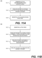
- FIGS. 1A-1B , 2 , 3A-3B , 4A-4B , and 10 illustrate non-limiting examples of ground effect craft consistent with the present disclosure. Exemplary deflections of one or more sponsons of ground effect craft are described with reference to FIGS. 5A-5B . Exemplary control systems of ground effect craft are described with reference to FIGS. 6A-6B . Exemplary ground effect lift surfaces and stabilizing members are described with reference to FIGS. 7A-7D and 8A-8G . An exemplary sponson of ground effect craft is described with reference to FIGS. 9A-9D . An exemplary method of generating lift is described with reference to FIGS. 11A-11B . FIGS.
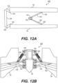
- FIGS. 13A-13G also describe exemplary folding mechanisms of a ground effect craft. It is understood that the examples and embodiments described represent simplified descriptions used to facilitate understanding of the principles and methods of this disclosure.
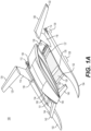
- FIG. 1A shows an exemplary embodiment of ground effect craft 100.
- ground effect craft 100 may include a first sponson 102, a second sponson 104, a body 106, a first ground effect wing 108, a second ground effect wing 109, a fore control system 128, and an aft control system 130.
- ground effect wings 108, 109 are shown stippled in FIG. 1A .
- Ground effect wings 108, 109 may operate to create a ground effect lifting force when the ground effect craft operates near a planetary surface.
- ground effect wings 108,109 may create a lifting force as ground effect craft 100 travels over water.
- ground effect wings 108, 109 may create an air cushion between a wing surface and a planetary surface.
- first ground effect wing 108 may include a first leading edge 131, a first main spar 134, and/or a first aft spar 136.
- Second ground effect wing 109 may include a second leading edge 132, a second main spar 135, and/or a second aft spar 137.
- Ground effect wings 108, 109 may include a first shaped leading edge 131 and a second shaped leading edge 132 to direct air flow in a way that facilitates lift.
- ground effect wings 108, 109 may include a rigid or semi-rigid structure to maintain an airfoil shape configured to generate lift.
- ground effect wing 108, 109 may include a flexible or semi-flexible material to entrap air and/or generate lift. Such flexible or semi-flexible material may be elastic or non-elastic.
- ground effect wings 108, 109 may be comprised of the rigid, semi-rigid, semi-flexible, or flexible material without one or more of main spars 134, 135 or aft spars 136, 137.
- ground effect wings 108, 109 may include a plurality of aerodynamic surfaces or control surfaces connected to each other.
- Ground effect wings 108, 109 may operate to generate a lifting force for body 106 as ground effect craft 100 moves along a planetary surface.
- first and second ground effect wings 108, 109 may be connected to respective sides of body 106.
- ground effect wings 108, 109 may be substantially continuous between first sponson 102 and second sponson 104, and may form a single wing.
- Ground effect wings 108, 109 may be configured such that ground effect wings 108, 109 may move relative to sponsons 102, 104. Ground effect wings 108, 109 may generate lift regardless of the movement of sponsons 102, 104 relative for example, due to sponsons 102, 104 striking an obstacle or perturbation on a planetary surface, which may cause sponsons 102, 104 to pitch and/or heave.
- ground effect wings 108, 109 are configured to substantially seal with sponsons 102, 104, respectively, to increase pressure underneath ground effect wings 108, 109 when ground effect craft 100 is in motion.
- ground effect wings 108, 109 and sponsons 102, 104 may be configured to allow movement of sponsons 102, 104 relative to ground effect wings 108, 109 while maintaining an air cushion beneath ground effect wings 108, 109. That is, in some embodiments, sponsons 102, 104 may be configured to deflect, for example, in pitch and/or heave, while ground effect wing remains relatively stable with respect to body 106.
- ground effect wings 108,109 may comprise a solid surface.
- ground effect wings 108,109 may comprise a semi-flexible, flexible, semi-elastic, or flexible elastic or non-elastic membrane surface.
- the membrane surface may be fixed to one or more spars 131, 132, 134, 135, 136, 137.
- the membrane surface may be configured to act against, but not be coupled to, one or more spars 131, 132, 134, 135, 136, 137.
- one or more spars 131, 132, 134, 135, 136,137 may control the deflection of the membrane to facilitate generating lift.
- the membrane surface may connect to an endplate.
- Fore control system 128 may be configured to dynamically connect sponsons 102, 104 to body 106 to allow sponsons 102, 104 to move in pitch and/or heave without transferring motion to body 106 and each other, while aft control system 130 is configured to connect first sponson 102 to second sponson 104 such that sponson 102, 104 move in pitch and/or heave without substantially transferring motion to each other.
- Fore control system 128 and aft control system 130 are configured to allow generally vertical movement of the front of sponsons 102, 104 relative to one another and body 106, and allow relative movement of the rear of sponsons 102, 104 such that stability is improved when sponsons 102, 104 strike obstacles or perturbations of a planetary surface as ground effect wings 108, 109 generate lift for body 106, therefore body 106 and ground effect wings 108, 109 move substantially less or do not move in response to the pitch and/or heave of sponsons 102, 104.
- Fore control system 128 and aft control system 130 may operate to allow sponsons 102,104 to move relative to body 106 when sponsons 102, 104 move in heave and pitch, as further discussed herein.
- fore control system 128 may dynamically connect first sponson 102 to body 106 and second sponson 104 to body 106.
- Fore control system 128 may be configured to allow first sponson 102 to move relative to body 106 and second sponson 104.
- First sponson 102 may move relative to body 106 such that a force acting on first sponson 102 is at least partially isolated from and does not substantially transmit the force to body 106 to cause substantial movement of body 106.
- Fore control system 128 may be configured to allow second sponson 104 to move relative to body 106 and first sponson 102.
- Second sponson 104 may move relative to body 106 such that a force acting on second sponson 104 does not substantially transmit the force to body 106 in a way that causes substantial movement of body 106.
- First sponson 102 and second sponson 104 may also be configured such that a force acting on either first sponson 102 or second sponson 104 is at least partially isolated from and does not substantially transmit the force to the other sponson, thereby allowing relatively independent movement of sponsons 102 and 104 effected by a force.
- sponsons 102, 104 may be at least partially decoupled in movement from body 106, thereby increasing stability and reducing instability of the ground effect craft when sponsons 102, 104 deflect in pitch and/or heave. This is because the relative movement of body 106 and/or ground effect wings 108, 109 is mitigated.
- any instability caused by one sponson moving in pitch and/or heave is at least partially isolated from the other sponson and the body.
- fore control system 128 may be positioned in front of a longitudinal center of gravity of body 106. In some embodiments, fore control system 128 may include a single control link (not shown). In some embodiments, fore control system 128 may include a plurality of control links. In some embodiments, fore control system 128 may include one or more flexible members, dynamic connections, and/or fixed connections. Fore control system 128 may include first and second main spars 134, 135. Fore control system 128 may include one or more rigid members and at least one dynamic connection such as, for example, to connect the rigid members to sponsons 102, 104 or body 106.
- a dynamic connection may include one or more hinges, pivots, bearings, joints (such as ball joints), springs, and/or dampeners, or any other connection configured to permit motion between the connected objects, such as, for example, between the rigid or flexible member and sponsons 102, 104 or body 106.
- Fore control system 128 may include at least one flexible member, which may act as a dampener and/or spring such as a thin-walled beam.
- Dynamic connections allow independent movement of, for example, sponson 102, 104, such that sponsons 102, 104 move relative to body 106 and each other without causing disruption to body 106, thereby increasing stability or reducing or mitigating an unstable condition of the overall craft, such as caused by pitching of one or both of sponsons 102, 104.
- fore control system 128 may include a rigid or semi-rigid member extending between first sponson 102 and body 106, the connection may include a hinge, bearing, pivot, or joint (such as a ball joint) configured to allow rotation of first sponson 102 relative to body 106.
- fore control system 128 may include a first control link extending from first sponson 102 to body 106.
- fore control system 128 may include a second control link extending from first sponson 102 to body 106.
- the control links may assume the shape of an airfoil section to reduce aerodynamic drag.
- control links may include a super-cavitating leading edge to reduce hydrodynamic drag.
- control links may include a center of rotation forward of a planar center of area of the control link, thereby aligning along the airflow and/or hydrodynamic flow to reduce drag.
- the control links may include an inverse u-shape member that spans from body 106 to a first sponson 102 or a second sponson 104 to increase clearance from a planetary surface.
- Aft control system 130 may dynamically connect first sponson 102 to second sponson 104.
- Aft control system 130 may be configured to allow first sponson 102 to move relative to second sponson 104.
- First sponson 102 may move relative to second sponson 104 such that a generally vertical force on first sponson 102 does not substantially transmit the force to second sponson 104 in a way that causes substantial movement of second sponson 104.
- aft control system 130 may be positioned behind the longitudinal center of gravity of sponson 102, 104.
- Aft control system 130 may include one or more rigid or semi-rigid members, a dynamic connection, and/or a fixed connection.
- a dynamic connection may include one or more hinges, pivots, joints (such as ball joints), springs, and/or dampeners, or any other connection that permits motion between the connected objects.
- Aft control system 130 may include a flexible or semi-flexible member, such as a torsion bar.
- aft control system 130 may include a single control arm, such as aft control link 138.
- aft control system 130 may include a plurality of control arms.
- aft control system 130 may include a plurality of aft control links or control arms (not shown).
- Such plurality of links or arms may be configured with a geometry, such as a parallelogram, trapezoidal, or triangular geometry, to reduce instability of ground effect craft 100 while permitting relative movement of at least one sponson.
- a parallelogram geometry may be configured to assist in maintaining sponsons 102, 104 substantially parallel to each other.
- aft control system 130 may include a rigid or semi-rigid member, such as aft control link 138, extending between first sponson 102 and second sponson 104, the connection having a hinge, bearing, pivot, or joint (such as a ball joint) to allow rotation or movement of first sponson 102 relative to second sponson 104.
- aft control system 130 may include one or more flexible or semi-flexible members and fixed or dynamic connections.
- aft control system 130 may include at least one flexible or semi-flexible member configured to act as a dampener and/or spring, such as a flexible beam, extending between first sponson 102 and second sponson 104.
- body 106 may include a resting surface configured to rest on aft control link 138, for example, when the ground effect craft is stationary or moving at a low velocity.
- the resting surface may include shock absorption materials or devices, for example, to absorb forces imparted from aft control link 138 to body 106 or from body 106 to aft control link 138.
- Ground effect wings 108, 109 and sponsons 102, 104 may form an air cushion beneath ground effect winds 108, 109 to create a lifting force on ground effect craft 100.
- the air cushion may, in some embodiments, stabilize ground effect craft 100.
- Ground effect wings 108, 109 are substantially sealed with first and second sponsons 102, 104 to increase the pressure of the air cushion.
- Ground effect wings 108, 109 may include one or more ground effect wing flaps 110.
- Ground effect wing flap 110 may move relative to a connection to ground effect wings 108, 109.
- Ground effect wing flap 110 may be configured to move relative to a planetary surface to increase or decrease lift.
- ground effect wing flap 110 may be configured to move towards a planetary surface to increase lifting pressure of the air cushion, generating lift and/or causing body 106 to pitch downward.
- ground effect wing flap 110 may be positioned behind the center of gravity of body 106 and/or sponsons 102, 104.
- Ground effect wing flap 110 may include a reinforcing structure configured to increase stiffness when the ground effect flap 110 moves upward due to, for example, air pressure created under ground effect wings 108, 109. This increased stiffness may result in a lifting force near the rear of ground effect wings 108, 109 thereby causing a nose-down moment on the front of ground effect craft 100.
- Ground effect wing flap 110 may include a dampening layer configured to mitigate and/or eliminate an impact force from a planetary surface transmitted to ground effect wings 108, 109.
- each of ground effect wings 108, 109 may include a ground effect wing flap 110.
- a single ground effect wing flap may connect ground effect wings 108, 109.
- the reinforcing members, the ground effect wings, and/or the flap may be of a composite construction with a laminate schedule configured to provide a predetermined resistance to deflection at varying aerodynamic and/or hydrodynamic pressures or impacts.
- the laminate schedule may include a dampening material.
- the laminate schedule may be configured to have an increased stiffness at an interior portion of the flap and a decreased stiffness at an edge portion of the flap.
- the laminate schedule may be configured to have an increased stiffness at an edge portion of the flap and a decreased stiffness at an interior portion of the flap.
- a first marine surface drive 112 and a second marine surface drive 114 may be coupled to first sponson 102 and second sponson 104, respectively.
- Marine surface drives 112, 114 may include marine motors (not shown) installed in sponsons 102, 104. In some embodiments, one or more marine outboard motors may be fixed at the location of marine surface drives 112, 114. In some embodiments, one or more marine drives (not shown) may be coupled to body 106 instead of, or in addition to, surface marine drives 112, 114.
- Non-limiting examples of marine drives 112, 114 may include pod drives, surface drives, jet drives, stern drives, inboard drives, folding surface shaft drive, and outboard drives.
- Embodiments of some propulsion systems may include, for example, a surface or shaft drive comprising hydro-pneumatic dampening of the vertical trim actuators.
- the drives may be configured to control the direction of ground effect craft 100.
- Non-limiting examples of marine motors may include inboard motors, and/or outboard motors and/or electric motors.
- one or more aerodynamic motor may be coupled to one or both of the sponsons.
- propulsion systems may include at least one aerodynamic motor and/or aerodynamic propulsion system that may include, for example, a propeller, ramjet, and/or force-generating device connected to one or more of body 106, ground effect wings 108, 109, and/or sponsons 102, 104.
- Sponsons of ground effect craft 100 may include aerodynamic surfaces configured to control the direction of ground effect craft 100. Aerodynamic surfaces of the sponsons of ground effect craft 100 may be configured to provide lift to and/or stabilize the sponsons.
- first sponson 102 may include a first vertical stabilizing surface 116. First vertical stabilizing surface 116 may be configured to stabilize first sponson 102 when ground effect craft 100 is in motion.
- first sponson 102 may include a first horizontal stabilizing surface 120 connected to first sponson 102 and/or first vertical stabilizing surface 116.
- First horizontal stabilizing surface 120 and/or first vertical stabilizing surface 116 may include a first stabilizing control surface 124.
- First stabilizing control surface 124 may stabilize first sponson 102 when ground effect craft 100 is in motion, such as when turning. For example, first stabilizing control surface 124 may change position to cause first sponson 102 to roll in a desired direction.
- second sponson 104 may include a second horizontal stabilizing surface 122 connected to second sponson 104 and/or second vertical stabilizing surface 118.
- Second vertical stabilizing surface 118 may be configured to stabilize second sponson 104 when ground effect craft 100 is in motion.
- Second horizontal stabilizing surface 122 and/or second vertical stabilizing surface 118 may include a second stabilizing control surface 126.
- Second vertical stabilizing surface 118 may be configured to stabilize second sponson 104 when ground effect craft 100 is in motion, such as when turning.
- second sponson 104 may include a second horizontal stabilizing surface 126 connected to second sponson 104 and/or second vertical stabilizing surface 118.
- Second horizontal stabilizing surface 122 may include the second stabilizing control surface 126.
- second stabilizing control surface 126 may change position to cause second sponson 104 to roll in a desired direction.
- horizontal stabilizing surfaces 120, 122 may be configured as anhedral, dihedral, partially dihedral, partially anhedral, gull-wing, or inverted gull-wing surfaces.
- Stabilizing control surfaces 124, 126 may include, for example, at least one of an elevator, aileron a flap, a flaperon, spoiler, ailevon, split spoiler ailevon, or ailevator. Although discussed relative to control surfaces 124, 126, it is understood that this discussion applies to control surfaces of the various ground effect craft described herein, or otherwise encompassed by the principles disclosed herein. In some embodiments, one or more control surfaces may be actuated by automatic control systems including an autopilot.
- first and second stabilizing control surfaces 124, 126 may be configured to move first and second sponsons 102, 104, respectively, to control the direction of movement of ground effect craft 100.
- a ground effect craft may include canard wings to improve lift and control of the craft.
- body 106 may include a first canard surface 142 and a second canard surface 146.
- First and second canard surfaces 142, 146 may be configured to generate lift.
- First canard surface 142 may include a first canard control surface 144.
- Second canard surface 146 may include a second canard control surface 148.
- First and second canard surfaces 142, 146 may be wing surfaces positioned near the fore of body 106.
- canard surfaces 142, 146 may be configured to control lift by moving relative to a connection to canard surfaces 142, 146.
- canard surfaces 142, 146 may be configured to generate lift to and/or control a motion of body 106.
- canard control surfaces 144, 148 may stabilize body 106 when ground effect craft 100 is turning. For example, first canard control surface 148 may move to cause body 106 to roll in a desired direction. As a further example, first canard control surface 148 may move together with control surface 144 to cause body 106 to pitch in a desired direction.
- Body 106 may include a fuselage, which may include one or more of a cockpit, a passenger compartment, or a cargo bay.
- body 106 may include a planing surface configured to reduce drag if a planetary surface is near or adjacent to body 106 while ground effect craft 100 is in motion.
- body 106 may include a buoyant sponson or incorporate a sponson (not shown) within a hull of body 106.
- body 106 may include at least one actuating mechanism configured to lift body 106 relative to the sponsons, for example, as described below. In some embodiments, such actuating mechanisms may be configured to be controlled by automatic control systems.
- the body may be configured to float in water.
- body 106 may be supported; hydrostatically by the displacement of the mass of body 106 by buoyancy when floating, hydrodynamically by body planing lift at lower velocities, and/or aerodynamically by ground effect wings 108,109 at higher velocities.
- body 106 may include an undercarriage shield or at least one planning surface configured to protect fore control system 128 from impact with a planetary surface and/or an obstacle.
- a sponson such as sponsons 102, 104, may have a hull with surface features along the length of the hull, such as laminar flow interrupters, transverse steps, longitudinal steps, and/or strakes. For example, both longitudinal and transverse steps may reduce drag and increase longitudinal stability.
- a chine step for example, may be configured to operate as a spray rail.
- a longitudinal step may, for example, decrease drag and friction as compared to a conventional hull.
- Sponsons 102, 104 may also include other marine control surfaces that operate to change the direction of ground effect craft 100, such as, for example, trim tabs, interceptors, rudders, roll stabilizers.
- ground effect craft 100 may include three or more sponsons.
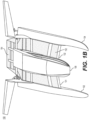
- FIG. 1B illustrates an exemplary embodiment of a ground effect craft 150.
- Ground effect craft 150 may be similar to those of exemplary ground effect craft 100 discussed with respect to FIG. 1A .
- the following description of ground effect craft 150 describes certain features of ground effect craft 150 that may vary from those of ground effect craft 100.
- Ground effect craft 150 includes a ground effect wing that extends along the length of body 106 length to increase the volume of the air cushion beneath the ground effect wing.
- ground effect craft 150 may include a ground effect wing 152 that extends from a leading edge to a trailing edge that is behind sponsons 102, 104.
- ground effect wing 152 may include an aft ground effect wing flap 154 configured to retain air pressure beneath ground effect wing 152.
- ground effect wing flap 154 may operate similar to flap 110 described herein.
- ground effect wing flap 154 may be configured to be raised, lowered, extended, and/or retracted to increase or decrease pressure and/or change the location of a center of pressure of ground effect wing 152.
- ground effect wing 152 and ground effect wing flap 154 may be configured to form a dynamic seal with sponsons 102, 104.
- the dynamic seal may be configured to allow pitch and heave moments of sponsons 102, 104 and/or body 106, thereby maintaining the pressure underneath ground effect wing 152. In some embodiments, the dynamic seal is configured to generate lift for sponsons 102, 104 and/or body 106.
- a rear portion of ground effect wing 152 may have a reverse delta or trapezoidal planform.
- the sides and/or endplates of ground effect wing 152 may be tapered inwardly towards the aft of ground effect craft 150.
- the sides and/or endplates near the rear of ground effect wing 152 may be sloped inwardly towards the upper surface of ground effect wing 152.
- ground effect wing flap 154 may have a reverse delta or trapezoidal planform.
- the sides and/or endplates of ground effect wing flap 154 may be tapered inwardly towards the aft of ground effect craft 150.
- the sides and/or endplates of ground effect wing flap 154 may be sloped inwardly towards the upper surface of ground effect wing flap 154.
- Ground effect craft 150 may be configured to create an air cushion underneath ground effect wing 152 during a transition between a stationary state and a moving state.
- ground effect craft 150 may include fingers that may be inflatable (not shown) along leading edges 131, 132 of ground effect wing 152. In some embodiments, the fingers may retract after ground effect craft 150 transitions from a stopped state to a moving state to increase lift generating by ground effect wing 152.
- ground effect craft 150 may include fans to generate pressure beneath ground effect wing 152 configured to lift ground effect craft 150.
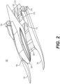
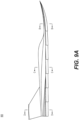
- FIG. 2 illustrates an exemplary embodiment of a ground effect craft 200. Certain features of ground effect craft 200 are not shown or discussed in these examples where such features may be similar to those discussed for other embodiments.
- FIG. 2 shows an exemplary ground effect craft 200.
- ground effect craft 200 may include a first sponson 102, a second sponson 104, a body 106, a first fore ground effect wing 108, a second fore ground effect wing 109, and an aft ground effect wing 210.
- Fore ground effect wings 108, 109 may include forward ground effect flap 110.
- Aft ground effect wing 210 may include aft ground effect flap 212.
- aft ground effect wing 210 may be connected to sponsons 102, 104.
- aft ground effect wing 210 may be positioned aft of sponsons 102, 104.
- aft ground effect wing 210 may be coupled to one or more sponsons, such as sponsons 102, 104. In some embodiments, aft ground effect wing 210 may be connected to an aft control link (not shown), such as, for example, aft control link 138. In some embodiments, first sponson 102 may include first propulsion system 216 and second sponson 104 may include second propulsion system 218 or other propulsion systems discussed herein.
- aft ground effect flap 212 may have features similar to aft ground effect flap 154. In some embodiments, an angle of ground effect flaps 212, 214 may be adjusted for varying desired lift, obstacle clearance, docking, weight distribution, or weight transfer.
- aft ground effect wing 210 may have a reverse delta or trapezoidal planform.
- the sides and/or endplates of aft ground effect wing 210 may be tapered inwardly towards the aft of ground effect craft 200.
- the sides and/or endplates of aft ground effect wing 210 may be sloped inwardly towards the upper surface of aft ground effect wing 210.
- aft ground effect wing flap 212 may have a reverse delta or trapezoidal planform.
- the sides and/or endplates of aft ground effect wing flap 212 may be tapered inwardly towards the aft of ground effect craft 200.
- the sides and/or endplates of aft ground effect wing flap 212 may be sloped inwardly towards the upper surface of aft ground effect wing flap 212.
- Aft ground effect wing 210 may be positioned substantially aft of fore ground effect wing 108, 109.
- Aft ground effect wing 210 may, for example, generate lift aft of the longitudinal center of gravity of sponsons 102,104 thereby creating a stabilizing downward pitching moment on the plurality of sponsons.
- the center of pressure of aft ground effect wing 210 may also be aft of both the longitudinal center of gravity and the center of pressure of the fore ground effect wings 108, 109 such that the downward pitching moment induced by aft ground effect wing 210 on the sponsons assists in stabilizing the ground effect craft.
- aft ground effect wing 210 mitigates instability of ground effect craft caused when sponsons 102, 104 move in pitch and/or heave, such as when a force is imparted from a planetary surface.
- aft ground effect wing 210 may be configured to generate a stabilizing moment on sponsons 102, 104 when an angle of attack of body 106 and/or pitch of sponsons 102/104 is increased.
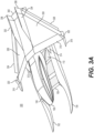
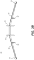
- FIGS. 3A-3B illustrate exemplary embodiments of a ground effect craft 300. Certain features of ground effect craft 300 are not shown or discussed in these examples where such features may be similar to those discussed for other embodiments.
- the center of pressure of stabilizing wing 310 may be aft of the longitudinal center of gravity of body 106.
- stabilizing wing 310 may operate to counteract an unstable moment of ground effect craft 300.
- stabilizing wing 310 may be configured to provide lift to an aft portion of body 106.
- stabilizing wing 310 may be connected to body 106.
- stabilizing wing 310 may be connected to one or more of sponsons 102, 104.
- stabilizing wing 310 may operate to counteract forces, such as pitching moments, on body 106 by being positioned aft and/or above body 106.
- stabilizing wing 310 may operate to counteract forces on body 106 by operating at a distance sufficient to increase a torque of a control surface of stabilizing wing 310 on body 106 and/or ground effect wings 108, 109.
- stabilizing wing 310 may include a surface area greater than ground effect wings 108, 109, thereby allowing a control surface of stabilizing wing 310 to generate a moment greater than a moment of ground effect wings 108, 109.
- stabilizing wing 310 may be configured to generate a stabilizing moment on body 106 and/or ground effect wings 108, 109 when an angle of attack of body 106 and/or ground effect wings 108, 109 is increased.
- the at least partial isolation pitch and/or heave of sponsons 102, 104 from each other and from body 106 mitigates a hydrodynamically-induced pitching moment on ground effect wings 108, 109 when sponsons 102, 104 pitch and/or heave.
- the at least partial isolation also mitigates or prevents blanketing of stabilizing wing 310 that may be caused by hydrodynamically-induced pitching of ground effect wings 108, 109. Mitigating or preventing blanketing of stabilizing wing 310 may reduce instability of the ground effect craft.
- control surfaces 320, 322, 324, 326, 336, 338, and 340 may operate to provide stability attitude and directional control for ground effect craft 300.
- one or more control surfaces 320, 322, 324, 326, 336, 338, and 340 may operate in conjunction to facilitate a change of direction or stabilize ground effect craft 300.
- the horizontal center of stabilizing wing 310 may be positioned substantially higher than ground effect wings 108, 109.
- stabilizing wing 310 may generate lift for a rear portion of body 106.
- wings 328, 330 may include an anhedral wing. In some embodiments, wings 328, 330 may include a dihedral, partially dihedral, partially anhedral, gull-wing, or inverted gull-wing. In some embodiments, stabilizing wing 310 may have a reverse delta configuration. In some embodiments, stabilizing wing 310 may comprise one or more transverse wings. It is also contemplated that propulsion systems may include at least one aerodynamic motor and/or aerodynamic propulsion system that may include, for example, a propeller, ramjet, and/or force-generating device connected to stabilizing wing 310.
- wings 328, 330 may comprise a solid surface. In some embodiments, wings 328, 330 may comprise a semi-flexible, flexible, semi-elastic, or flexible elastic or non-elastic membrane surface.
- Sponsons 102, 104 of ground effect craft 300 may be configured to support weight of stabilizing wing 310 and partial weight of the body 106 when ground effect craft 300, such as when ground effect craft 300 is substantially stationary.
- sponsons 102, 104 may include structural vertical stabilizers 312, 314. that may support the weight of stabilizing wing 310 and/or partial weight rear portion of body 106.
- structural vertical stabilizers 312, 314 may include a dampening mechanism 386, 387 of FIG 3B , such as one or more springs, shock absorbers, and/or dampeners, to absorb the impact energy when stabilizing wing 310 makes contact with structural vertical stabilizers 312, 314.
- FIG. 3B illustrates a cross-section of an exemplary stabilizing wing 310.
- the ground effect craft may include an anhedral wing configured to counter a lack of aerodynamic roll with sideslip.
- Stabilizing wing 310 may, for example, include an anhedral wing in some embodiments.
- At least one wing surface of a ground effect craft may comprise solar cells or panels. Such solar cells or panels may be configured to power electric motors or charge batteries of the ground effect craft.
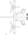
- FIGS. 4A and 4B illustrate exemplary embodiments and configurations of an aircraft 400. Some features of aircraft 400 are not shown or discussed in these examples where such features may be similar to those discussed for other embodiments.
- Aircraft 400 may include a first sponson 102 and a second sponson 104 that move relative to body 406 and each other.
- Body 406 may include ground effect wings 108, 109.
- first sponson 102 may encounter a surface causing first sponson 102 to pitch and/or heave relative to body 406 and second sponson 104.
- Ground effect wings 108, 109 may generate lift for aircraft 400.
- ground effect wings 108, 109 are substantially sealed with sponsons 102, 104, respectively, to form an air cushion underneath ground effect wings 108, 109, such as the sealing methods described herein.
- ground effect wings 108, 109 may be configured to generate lift as aircraft 400 transitions between a takeoff mode and a flying mode.
- the takeoff mode may be a configuration of aircraft 400 while stopped, taxiing, or increasing speed to generate enough lift to enter a flying mode on a planetary surface, such as snow, ice, water, or land.
- sponsons 102, 104 may be configured to retract or deflect on impact, thereby absorbing a landing impact when aircraft 400 transitions between the flying mode and a landing mode.
- an exemplary fore control system 428 may include first and second lower control links 410, 416, first and second upper control links 412, 418, and/or first and second actuators 414, 420.
- An aft control system may dynamically connect first sponson 102 to second sponson 104.
- a variety of control systems 428 are contemplated to allow movement of one or more sponsons relative to a body of a ground effect craft, such as a control system similar to fore control system 128 an/or aft control system 130.
- first and second actuators 414, 420 may be configured to support the resting mass of aircraft 400, absorb an impact from a planetary surface, and/or extend or retract sponsons 102, 104, for example, on takeoff and landing. In some embodiments, first and second actuators 414, 420 may be configured to permit deflection of sponsons 102, 104 in response to a strong force applied to sponsons 102, 104, such as striking an obstacle or striking a wave or other perturbation in a planetary surface.
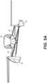
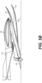
- FIGS. 5A and 5B illustrate exemplary relative motions of sponsons 102, 104 of exemplary ground effect craft. Although discussed relative to sponsons 102, 104, it is understood that this discussion applies to sponsons of the various ground effect craft described herein, or otherwise encompassed by the principles disclosed herein. Some features of the exemplary ground effect craft are not shown or discussed in these examples where such features may be similar to those discussed for other embodiments.
- FIG. 5A illustrates an example embodiments and principles of at least partial isolation of body 106 from pitching, heaving, or other movement moments of sponsons 102, 104.
- FIG. 5A also illustrates the effect of an obstacle, perturbation of a planetary surface, or other force causing sponson 102 to pitch and heave upward relative to body 106 and second sponson 104.
- FIG. 5A illustrates sponson 104 heaved downward relative to body 106 and first sponson 102.
- sponsons 102, 104 may not be completely isolated in movement from body 106 and each other because of the connection between them; however, the dynamic coupling and movement isolation is sufficient to avoid transferring a substantial amount of movement between sponson 102, sponson 104, and body 106, thereby stabilizing (and reducing instability) of the ground effect craft when one or both of sponsons 102, 104 move in pitch, heave, and/or other motions imparted by forces, such as impact with a planetary surface.
- first and second sponsons 102, 104 may be configured to move relative to body 106 without substantially transferring the movement to body 106 or each other.
- ground effect wings 108, 109 may be configured to flex when sponson 102 and/or 104 move relative to body 106 and make contact with ground effect wings 108, 109.
- ground effect wings 108, 109 may be configured to flex with one or more of first and second main spars 134, 135, as result of movement of sponsons 102, 104 which makes contact with ground effect wings 108, 109.
- control a control system such as, for example, control systems 128 and/or 130 (not shown) dynamically coupling sponsons 102, 104 to body 106, and/or sponson 102 to sponson 104.
- control systems 128 and/or 130 dynamically coupling sponsons 102, 104 to body 106, and/or sponson 102 to sponson 104.
- Such dynamic coupling permits pitch and/or heave of one sponson while increasing stability or mitigating or eliminating instability
- FIG. 5B also shows the movement of aft ground effect wing 210 relative to body 106.
- aft ground effect wing 210 may be configured to move relative to body 106 and sponsons 102, 104, such as when contacting planetary surface 550, thereby reducing craft failure.
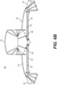
- FIGS. 6A and 6B illustrate exemplary embodiments of ground effect craft 600. Certain features of ground effect craft 600 are not shown or discussed in these examples where such features may be similar to those discussed for other embodiments.
- Ground effect craft 600 may be configured to allow at least partially isolated movement of sponsons 102, 104 relative to body 106 and each other in a way that does not substantially transfer the motion of one or both of sponsons 102, 104 to body 106 or the other sponson.
- ground effect craft 600 may include fore control system 128 and aft control system 130.
- fore control system 128 may include a first fore control link 662 dynamically connecting first sponson 102 to body 106 and a second fore control link 664 dynamically connecting second sponson 104 to body 106.
- aft control system 130 may include an aft control link 658 dynamically connecting first sponson 102 to second sponson 104.
- First fore control link 662 may also include first fore supporting member 650 coupled to body 106.
- Second fore control link 664 may include second fore supporting member 652 coupled to body 106.
- aft control link 658 may include first aft supporting member 654 and second aft supporting member 656 connected to sponsons 102, 104.
- First and second fore supporting members 650, 652 and first and second aft supporting members 654, 656 may be configured to provide yaw control by coupling of the body 106 with sponsons 102,104 when acting with control links 658, 662.
- fore supporting members 650, 652 and fore control links 662, 664 are positioned in substantially the same plane with each other and with actuators 628, 630 (shown in FIG. 6B ).
- supporting members 650, 652, 654, 656 may be positioned in substantially the same plane as control links 662, 664, 658.
- one or more supporting members 650, 652, 654, 656 may be at a plane different from control links 658, 662, 664.
- supporting members 654, 656 and control link 658 are in substantially the same plane as each other and with aft flap actuators (such as actuators 741, 742 of FIG. 7C ).
- supporting members 650, 652, 654, 656 may connect to control links 662, 664, 658 anywhere along the length of the control link.
- control links 658, 662, 664, and supporting members 650, 652, 654, 646 may be rigid, semi-rigid, flexible, or semi-flexible.
- aft control link 658 is configured to connect first sponson 102 and second sponson 104.
- Aft control link 658 may substantially span the distance between first sponson 102 and second sponson 104.
- Aft control link 658 may be dynamically connected to first sponson 102 and second sponson 104 via a plurality of ball joints. At least one ball joint in the plurality of ball joints may allow movement of first sponson 102 relative to second sponson 104.
- ball joints may be used in this example, other methods of dynamically connecting aft control link 658 to first and second sponsons 102, 104 are known to those of skill in the art and contemplated herein, and may be use in addition to or in the alternative of ball joints.
- Such connections include, but are not limiting to hinges, pivots, joints (such as ball joints), springs, and/or dampeners.
- aft control link 658 may include a flexible or semi-flexible beam that is fixedly connected to first and second sponson 102, 104, such that the flexibility of aft control link 658 permits sponsons 102, 104 to move relative to each other without substantially transferring motion from one sponson to the other.
- aft control link 658 may include a rigid or semi-rigid beam.
- control link 658 may include a plurality of links so as to collectively act as a parallelogram with sponsons 102, 104.
- a single fore link or spar connection from the body 106 to sponsons 102, 104 is contemplated.
- FIG. 6B illustrates aspects of ground effect craft 600.
- FIG. 6B shows a non-limiting embodiment of a fore control system, such as fore control system 128.
- Ground effect craft 600 may include a first main spar 134 dynamically connecting body 106 to first sponson 102 and a second main spar 135 dynamically connecting body 106 to second sponson 104 to allow deflecting movement of sponsons 102, 104 relative to body 106 and each other.
- Main spars 134, 135 may allow movement of first sponson 102 and second sponson 104 relative to body 106 and each other.
- Main spars 134, 135 may be configured to dampen or absorb forces, such as created by pitch and/or heave, imparted on sponsons 102, 104 so that the force transmitted to body 106 is reduced and/or relatively isolated by main spars 134, 135 from body 106.
- body 106 may be at least partially isolated in heave and/or pitch from sponsons 102, 104 by flexing of spars 134, 135.
- body 106 may be at least partially decoupled in pitch from sponsons 102, 104 by one or more hinges, bearings, pivots, or joints (such as a ball joint) connecting spars 134, 135 to sponsons 102,104.
- one or more hinges, bearings, pivots, or joints may connect to an end plate (not shown) fixed to main spars 134, 135 to sponsons 102, 104.
- main spars 134, 135 may be configured to contact with one or more sponsons 102, 104 to support the mass of body 106 at rest or until aerodynamic lift is sufficient to support body 106. In some embodiments, such support may be provided by end plates (not shown) fixed to main spars 134, 135. In some embodiments, main spars 134, 135 may be configured to increase load bearing strength, for example, by having a substantially concave shape facing downward of ground effect craft 600.
- a fore control system may include a rigid frame and a dampening system.
- the rigid frame may span or substantially span the distance between first sponson 102 and second sponson 104.
- the rigid frame may be connected to first sponson 102 and second sponson 104 by a plurality of dampeners.
- the plurality of dampeners may reduce and/or eliminate the force transmitted from, for example, first sponson 102 to body 106.
- the plurality of dampeners may include one or more of a plurality of springs, pneumatic cylinders, and/or dynamically or statically pressurized air bags.
- the plurality of dampeners may facilitate movement of first sponson 102 relative to body 106 and second sponson 104.
- the plurality of springs may allow movement of second sponson 104 relative to body 106 and first sponson 102.
- the dampeners and/or springs may be mounted substantially near body 106. In some embodiments, the dampeners and/or springs may be mounted substantially near sponsons 102, 104.
- Control links 612, 614, 616, and 618 may be configured to allow first sponson 102 and/or second sponson 104 to travel relative to body 106.
- Control links 612, 614, 616, 618 may be rigid or flexible.
- control links 612, 614, 616, and 618 may be of a length such that the travel of sponson 102, 104 relative to body 106 is large for a small angle of deflection from one position of control links 612, 614, 616, and 618 to another position.
- main spars 134, 135 may be configured to rest on top control links 612, 616.
- Control links 612, 614, 616, 618 and supporting links 650, 652 may be dynamically connected to first sponson 102, second sponson 104, and/or body 106 via one or more movable connections, such as, for example, one or more hinges, bearings, pivots, or joints (such as a ball joint). At least one connection in the plurality of movable connections may allow movement of sponsons 102, 104 relative to body 106. It is contemplated that other movable connections may be used to dynamically connect control links 612, 614, 616, 618 and supporting links 650, 652 to first and second sponsons 102, 104.
- Ground effect craft 600 may include first actuator 628 and second actuator 630.
- first and second actuators 628, 630 may be connected to top control links 612, 616.
- first and second actuators 628, 630 may be connected to bottom control links 614, 618.
- first and second actuators 628, 630 may be configured to move body 106 relative to top control links 612, 616.
- first and second actuators 628, 630 may be configured to move body 106 relative to first and second sponsons 102, 104 to raise body 106 above a planetary surface.
- first and second actuators 628, 630 may be configured to increase the stiffness of one or more control links such that surface clearance, dampening, and/or springing rates of such links may be increased to match passenger and/or cargo loading of ground effect craft 600.
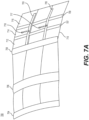
- FIGS. 7A-7D illustrate exemplary embodiments of aerodynamic surfaces of a ground effect craft, such as described herein. Certain features of the ground effect craft are not shown or discussed in these examples where such features may be similar to those discussed for other embodiments, such as, for example, those discussed herein regarding ground effect wings, control systems, and flaps.
- FIG. 7A illustrates exemplary ground effect wing 700.
- ground effect wing 700 may include a leading edge spar 704 and/or a main spar 706.
- main spar 706 may include portions of fore control system 128. Alternatively, main spar 706 may be positioned above or below fore control system 128.
- ground effect wing 700 may include a trailing edge spar 708.
- ground effect wing 700 may include ground effect flap 710.
- ground effect flap 710 may be extendable from a position proximate trailing edge spar 708.
- ground effect wing 700 is shown in FIG. 7A , it is contemplated that a ground effect wing me be positioned on either side of body 106 such as ground effect wings 108, 109 in FIG. 1A .
- a single ground effect flap 710 may be coupled to both ground effect wings, or, in some embodiments, each ground effect wing may include a separate ground effect flap 710.
- ground effect flap 710 may include longitudinal battens 703, 705, and transverse battens 707, 709.
- ground effect flap 710 may be composed of a single panel. In some embodiments, ground effect flap 710 may be composed of a plurality of overlapping panels, such as panels 712, 714, 716. In some embodiments, overlapping panels may be configured to permit localized deflection when one or more panels contacts a planetary surface and the other panels may not. In some embodiments, this may isolate a local deflection and prevent a loss of pressure of an air cushion pressure. In some embodiments, overlapping panels may be configured to increase resistance of ground effect flap 710 as it deflects upwards.
- ground effect wing 700 may include ground effect flap 710 configured to rotate around a connection to increase lift and/or change the center of pitch of ground effect wing 700.
- ground effect wing 700 may include a first flap actuator 718.
- Ground effect wing 700 may also include a second flap actuator 717.
- ground effect wing flap 710 may include one or more longitudinal battens, such as a first longitudinal batten 703 and a second longitudinal batten 705.
- flap actuators 717, 718 may be configured to move against first and second battens 703, 705, respectively, to move ground effect flap 710.
- flap actuators 717, 718 may include one or more electromechanical actuators, hydraulic actuators, or pneumatic actuators.
- the wing flap 710 may be actuated by at least one pneumatically pressurized membrane lobe.
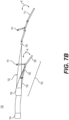
- FIG. 7B illustrates an exemplary cross-section of an exemplary ground effect wing 750.
- Ground effect wing 750 may include a primary ground effect wing 702.
- ground effect wing 750 may include a mid-flap 752.
- mid-flap 752 may be configured to extend from ground effect wing 750 at a location between a leading edge and a trailing edge of ground effect wing 750.
- Mid-flap 752 may, in some embodiments, be configured to rotate about a connection (not shown) to ground effect wing 750 forward of aft spar 708.
- Mid-flap 752 may, in some embodiments, be configured to rotate about a connection to ground effect wing 750 at main spar 706.
- mid-flap 752 may include a plurality of overlapping panels, such as overlapping panels 754, 756, 758, that may operate as described herein for overlapping panels 712, 714, 716 of ground effect flap 710.
- mid-flap 752 may be configured to alter the position of the center of pressure of the ground effect craft wing 750. For example, at a slower speed, mid-flap 752 may operate to rotate downward and/or upward in the direction of rotation R, relative to ground effect wing 702 to move the center of pressure of the ground effect craft substantially forward and/or to control the pitch of the bow of body 106 relative to a planetary surface. At a faster speed, for example, mid-flap 752 may be configured to operate to rotate upward towards a ground effect wing to move the center of pressure substantially aft on a ground effect craft and/or to reduce drag, such as hydrodynamic drag.
- Ground effect wing 750 may, in some embodiments, include a middle flap actuator 751 configured to move mid-flap 752 relative to primary ground effect wing 702.
- mid-flap 752 may be configured to operate in conjunction with ground effect wing flap 710 to change the center of pressure and/or pitch of ground effect wing 750.
- the mid-flap actuator 751 may be controlled by automatic control systems including an autopilot which actuates relative to cushion pressure.
- FIG. 7C illustrates an exemplary embodiment of aft ground effect wing 740.
- FIG. 7C shows a non-limiting example of aft ground effect wing 210.
- Aft ground effect wing 740 may include an aft ground effect wing flap 729.
- Aft ground effect wing flap 729 may rotate around a connection to aft ground effect wing 740.
- aft ground effect wing 740 may include a plurality of overlapping panels, similar to the overlapping panels 712, 714, 716 of ground effect flap 710 to, for example, permit localized deflection when one or more panels contacts a planetary surface, when other panels do not.
- aft ground effect wing 722 may include a rotating member 748.
- rotating member 748 may include aft control link, such as aft control link 658 as discussed in reference to FIG. 6A .
- rotating member 748 may connect to actuators 741, 742 configured to rotate aft ground effect wing flap 729 upward or downward, such as in a direction illustrated by rotation R, to control a lift generated by aft ground effect wing 740.
- rotating member 748 may connect to actuators 741, 742 configured to rotate aft ground effect wing 740 upward or downward, such as in a direction illustrated by rotation R, to control a lift generated by aft ground effect wing 740.
- a ground effect craft may include a flap to increase control of the center of pressure of the ground effect wing 760.
- a fore ground effect flap 710 may operate to rotate, such as in a direction illustrated by rotation R1, away from the ground effect wing to move the center of pressure substantially forward on a ground effect craft and/or to raise the front of a body (not shown) relative to a planetary surface.
- fore ground effect flap 710 may operate to rotate towards a ground effect wing and away from the planetary surface to move the center of pressure aft on the ground effect craft and/or reduce hydrodynamic drag.
- fore ground effect wing 702 may include a fore ground effect actuator 717 to move fore ground effect flap 710 around a connection to fore ground effect wing 702.
- fore ground effect flap 710 may operate in conjunction with aft ground effect wing flap 738 to change the center of pitch of the ground effect craft, increase lift, and/or reduce drag.
- fore ground effect flap 710 may be configured to be deflected by aerodynamic pressure and/or a mechanism, such as an actuating mechanism.
- fore ground effect flap 710 may be configured to direct and/or restrict airflow towards aft ground effect wing 722.
- the movement of fore ground effect wing 702, such as fore ground effect flap 710 may direct air towards aft ground effect wing 722 when, for example, a trailing edge of fore ground effect wing 702/flap 710 increases in height above the planetary surface. This increase in height may cause the air at fore ground effect wing 702 to pass to aft ground effect wing 722 and increase a lift of aft ground effect wing 722, thereby stabilizing the ground effect craft and/or generating lift.
- deflection of the flap may be controlled by a flexural modulus or laminate modulus of the ground effect wing and/or ground effect flap 710.
- aft ground effect wing 722 may be configured to generate lift when at least a portion of fore ground effect wing 702, such as fore ground effect flap 710, moves to a height above a planetary surface. For example, as a portion of fore ground effect wing 702, such as a trailing edge of the wing or fore ground effect flap 710, lifts above the planetary surface airflow passes from fore ground effect wing 702 to aft ground effect wing 722, which generates lift at aft ground effect wing 722. The generation of lift at aft ground effect wing 722 causes sponsons 102, 104 to pitch downward, thereby mitigating destabilization and stabilizing sponsons 102, 104 and the ground effect craft.
- the portion of fore ground effect wing 702 may be configured to move to a height above the planetary surface via a mechanism, flexure of the wing and/or flap, increased aerodynamically induced pressure, and/or an attitude of a ground effect craft.
- a modulus of the portion of fore ground effect wing 702 may be such that the portion of the wing automatically deflects when a certain air pressure is reached at fore ground effect wing 702.
- the modulus is determined by a materials property of portion of the wing.
- the materials property may result from a composite or laminate schedule determining the modulus. The modulus may be varied for different applications or specifications for a desired deflection point.
- flexure modulus or materials property may be designed to provide a predetermined resistance to deflection at varying aerodynamic pressures.
- the modulus or property may be defined by a composite or laminate schedule.
- the composite or laminate may be configured to have an increased stiffness at an interior portion of the wing or flap portion and a decreased stiffness at an edge portion of the wing or flap portion.
- the laminate may be configured to have an increased stiffness at an edge portion of the wing or flap portion and a decreased stiffness at an interior portion of the wing or flap portion.
- the deflection of at least a portion of fore ground effect wing 702 may be controlled by a mechanism, such as an actuating mechanism, resistive mechanism, or reinforcing members.
- the mechanism may be configured to control the deflection at certain pressures to permit air to flow to aft ground effect wing 722.
- a compression or dampening mechanism, or flexure resistance of the resistive mechanism or reinforcing members may control the deflection of at least a portion of fore ground effect wing 702.
- a pneumatic mechanism may be configured to compress as pressure on fore ground effect wing 702 increases, such that at a certain pressure the resistance of the compression or dampening mechanism is overcome, thereby deflecting the portion of fore ground effect wing 702 above the planetary surface and directing airflow to aft ground effect wing 722.
- the increased pressure may overcome a flexure resistance of the resistive or reinforcing members, causing them to flex and permit deflecting the portion of fore ground effect wing 702 above the planetary surface and directing airflow to aft ground effect wing 722.
- a combination of modulus or materials properties of the wing and a mechanism may be used. Such embodiments may be configured to permit the portion of fore ground effect wing 702 to automatically direct airflow to aft ground effect wing 722, for example without an electronic control system.
- the deflection may be controlled by an electronic control system.
- At least one of; flap 710, flap segments 712, 714, 716, mid-flap 752, mid-flap segments 754, 756, 758 and aft ground effect wing 722 may include a dynamic seal.
- the dynamic seal may include one or more seals, such as, for example, discussed herein, to dynamically seal with sponsons 102, 104.
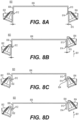
- FIGS. 8A-8G illustrate exemplary embodiments, according to the invention, of seals configurations between ground effect wing 806 and sponsons 802,804.
- ground effect wing 806 may contain one or more of the grounds effect wing features discussed herein.
- the seal configurations of ground effect wing 806 and sponsons 802 or 804 may be used to seal the various flap embodiments discussed herein.
- Ground effect wing 806 may be similar to the disclosure of ground effect wings 108, 109, or any other ground effect wing disclosed herein.
- the seal is configured to allow for movement of sponsons 802, 804 relative to ground effect wing 108 and/or 109, thereby maintaining the seal to entrap air and generate lift when sponsons 802, 804 deflect relative to the ground effect wing. It is contemplated that sealing examples in FIGS. 8A-8G may be used in combination with one another or alone in various embodiments described herein.
- the seal may include a preformed seal.
- the seal may comprise Teflon, rubber, high density molecular plastic seal, and/or other suitable material.
- FIG. 8A illustrates an exemplary sealing configuration 800.
- ground effect wing 806 may include first endplate 808 and second endplate 810.
- Endplates 808, 810 may be configured to entrap air beneath ground effect wing 806 while the ground effect craft is in motion, thereby producing lift.
- Endplates 808, 810 may be configured to extend downward to be substantially adjacent to a portion of sponsons 802, 804 when sponsons 802, 804 move relative to ground effect wing 806, such as in pitch and/or heave.
- first endplate 808 may include a first planing surface 812.
- second endplate 810 may include a second planing surface 814. Planing surfaces 812, 814 may reduce drag if the planing surfaces touch a planetary surface, such as water.
- first endplate 808 may be separated a separation distance 816 from first sponson 802, and second endplate 810 may be separated a separation distance 816 from second sponson 804.
- Separation distance 816 may be sufficient to allow sponsons 802, 804 to move relative to ground effect wing 806 without contacting ground effect wing 806.
- separation distance 816 may be sufficiently small to maintain an air cushion beneath ground effect wing 806 even though some air may pass through separation distance 816.
- At least one overlapping and/or telescoping sliding plate may extend from endplates 808, 810 to increase the sealed travel of ground effect wing 806 with respect to the dynamic movement of sponsons 802, 804 while maintaining the air cushion.
- Such sliding plates may be configured to slide on the inside of endplates 808, 810, thereby the pressure of the air cushion acts to maintain the seal.
- sponsons 802, 804 may include substantially flat surfaces facing endplate 808, 810 to provide a surface to seal air beneath ground effect wing 806.
- sponsons 802, 804 may include interior surfaces that are configured to form a surface along which endplates 808, 810 may move while mitigating cushion pressure loss from underneath ground effect wing 806.
- Such interior surfaces may include, for example, an inner surface of the sponson vertical stabilizers.
- FIG. 8B illustrates exemplary movement of second sponson 804 relative to ground effect wing 806 and first sponson 802 in FIG. 8A when second sponson 804 moves in heave direction 801.
- FIG. 8B illustrates second sponson 804 displaced upwards relative to ground effect wing 806 and first sponson 802 while separation distance 816 remains substantially small and/or negligible so as to entrap air and generate lift.
- FIG. 8C illustrates another exemplary sealing configuration 820.
- Configuration 820 may include a first seal 832 and a second seal 834.
- Ground effect wing 806, first endplate 808, first seal 832, second endplate 810, and second seal 834 may be configured to entrap air beneath ground effect wing 806.
- second seal 834 may extend from an inside surface of sponson 804 to a surface of second endplate 810.
- First and second seals 832, 834 may be configured to eliminate and/or reduce airflow from an area below ground effect wing 806 to an area above ground effect wing 806.
- FIG. 8D shows another exemplary sealing configuration 820 relative to ground effect wing 806 and first sponson 802 in FIG. 8C when second sponson 804 moves in heave direction 801.
- FIG. 8D illustrates second sponson 804 displaced upwards relative to ground effect wing 806 and first sponson 802 in direction 801.
- First seal 832 may be connected to first sponson 802.
- Second seal 834 may be connected to second sponson 804.
- First and second seals 832, 834 may be movable, such that seals 832, 834 may be configured to move with first and second sponsons 802, 804, respectively, when sponsons 802, 804 move relative to ground effect wing 806, such as shown in FIG. 8D .
- second seal 834 may move relative to ground effect wing 806 when second sponson 804 moves in heave and/or, as shown in FIG. 8D .
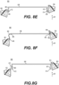
- FIG. 8E illustrates another exemplary sealing configuration 835.
- configuration 835 may include a first seal 836 and a second seal 838 that are fixed to the end plates 808, 810.
- Sponsons 802, 804 may move relative to seals 836, 838 and ground effect wing 806, for example, when second sponson 804 moves in heave and/or pitch, as shown in FIG. 8E .
- FIG. 8F illustrates another exemplary sealing configuration 840.
- Configuration 840 may include a first membrane 842 and a second membrane 844.
- First and second membranes 842, 844 may be connected to first and second sponsons 802, 804, respectively, and ground effect wing 806.
- ground effect wing 806 may not include end plates 808, 810 for connecting to membranes 842, 844.
- First and second membranes 842, 844 may be flexible to allow movement of first and second sponsons 802, 804, relative to ground effect wing 806 and each other without the friction or resistance associated with other types of seals, such as in configurations 820 and 835, such as when sponson 804 moves in heave and/or pitch, as shown in FIG. 8D .
- the entrapped air along the surfaces of ground effect wing 806 and first and second membranes 842, 844 may generate aerodynamic lift and/or reduce drag.
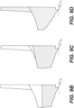
- FIG. 8G illustrates another exemplary sealing configuration 860.
- Configuration 860 may include a first endplate 868, a first membrane 872, a second endplate 870, and a second membrane 874.
- First and second membranes 872, 874 may be configured to connect first and second endplates 868, 870 to first and second sponsons 802, 804.
- Ground effect wing 806, first endplate 868, first membrane 872, second endplate 870, and second membrane 874 may be configured to entrap air below ground effect wing 806. The entrapped air along the surfaces of the ground effect wing and the first and second membranes may generate aerodynamic lift and/or reduce drag.
- a membrane seal (such as the examples in FIGS. 8F and 8G ) may comprise a break-away connection, such as, for example hook and loop fasteners or break-away stitching, configured to detach the membrane from the sponson and/or ground effect wing at certain angles or rotations. Such detachment, for example, may prevent a pitched sponson from pitching the ground effect wing when the membrane seal is at the limits of travel and/or fully taut.
- a break-away connection such as, for example hook and loop fasteners or break-away stitching
- a skirt (not shown) may be attached to sponsons 802, 804 and/or ground effect wing 806 and may enclose and/or partially enclose the air chamber beneath ground effect wing 806.
- the skirt may be inflatable.
- the skirt may retract when the ground effect craft is in motion.
- the skirt may maintain and/or increase air pressure beneath ground effect wing 806.
- FIGS. 9A-9D illustrate an exemplary embodiment of sponson 900 of a ground effect craft.
- FIG. 9 is non-limiting example that applies to sponsons 102, 104 and other sponsons discussed herein. Certain features of ground effect craft discussed herein are not shown or discussed in these examples where such features may be similar to those discussed for other embodiments.
- Sponson 900 may include bottom surfaces that include deadrise that varies along the length of sponson 900.
- Deadrise is angle formed between the bottom of a hull of sponson 900 and a horizontal plane.
- Sponson 900 may include bottom surfaces with varying deadrise to reduce hydrodynamic impact loads. Higher deadrise angles increase hydrodynamic drag but reduce hydrodynamic impact loads. Lower deadrise angles reduce hydrodynamic drag but increase hydrodynamic impact loads.
- deadrise may change along the length of sponson 900.
- the lowest deadrise angle is at or about the overall ground effect craft longitudinal center of gravity and increases both fore and aft of the longitudinal center of gravity.
- sponson 900 has an increased deadrise where the pitching moments have increased leverage about the longitudinal center of gravity and thereby increases longitudinal stability.
- sponson 900 may include transverse and longitudinal steps along its length.
- the sponson may include a lateral profile that minimizes a lateral surface area towards the fore of sponson 900.
- the sponson may include a lateral profile that maximizes a lateral surface area towards the aft of sponson 900.
- the sponson may have a lateral profile that minimizes the fore lateral surface area and maximizes the aft lateral surface area, thereby providing a center of lateral resistance of the sponson is proximate to the center of gravity of the sponson.
- the center of gravity of the sponson may be associated with the mass the sponson, including the mass or weight of an engine or other propulsion device.
- FIG. 9B shows a cross section B-B of sponson 900.
- sponson 900 may have an increased deadrise ⁇ 1 towards the front of the sponson, such as at cross section B-B.
- FIG. 9C shows a cross section C-C of sponson 900.
- sponson 900 may have a decreased deadrise ⁇ 2 towards the center of sponson 900, such as at cross section C-C.
- FIG. 9D shows a cross section D-D of sponson 900.
- sponson 900 may have an increased deadrise 83 towards the rear of sponson 900, such as at cross section D-D. It is also contemplated that, in some embodiments, deadrise may increase or decrease from front to rear of sponson 900 such as from cross-section B-B to cross-section D-D.
- FIGS. 10A-10C illustrate exemplary embodiments of a ground effect craft. Certain features of ground effect craft discussed herein are not shown or discussed in these examples where such features may be similar to those discussed for other embodiments.
- FIG. 10A illustrates ground effect wings 108, 109 connecting to a first side and a second side of body 106.
- FIG. 10B illustrates ground effect wing 1010 connected to the bottom of body 106.
- FIG. 10C illustrates ground effect wing 1010 substantially below body 106.
- FIGS. 11A-11B show exemplary methods of stabilizing a ground effect craft.
- the order and arrangement of steps in methods 1100 and 1140 are provided for purposes of illustration. As will be appreciated from this disclosure, modifications may be made to method 1100 and 1140 by, for example, adding, combining, removing, and/or rearranging the steps for methods 1100 and 1140.
- Method 1100 may include a step 1102 of generating lift via a first ground effect wing.
- the ground effect craft may move across a planetary surface and generate lift under the first ground effect wing, such as fore ground effect wings 108, 109.
- Generating lift via a first ground effect wing may be substantially independent of heave and/or pitch movement of a plurality of sponsons of the ground effect craft.
- method 1100 may include a step 1104 of stabilizing the body by dynamically coupling of a first sponson and a second sponson to the body.
- the ground effect craft may include a fore control system 128, that dynamically couples the body to a plurality of sponsons.
- the sponsons may be dynamically coupled to each other by an aft control system 130.
- the first ground effect wing may be a fore ground effect wing.
- the stabilizing via dynamic coupling may include at least partially isolating the movement of one sponson from the movement of the body and/or the other sponson. In some embodiments, this may include dynamic coupling such that a force imparted on one sponson is not substantially transferred to the body or the other sponson.
- method 1100 may include a step 1106 of generating lift via a second ground effect wing, such as an aft ground effect wing.
- the first ground effect wing may substantially restrict airflow and/or direct airflow towards the second ground effect wing.
- the second ground effect wing may be configured to generate lift when the first ground effect wing moves to a height above a planetary surface that, for example, allows airflow to reach the second ground effect wing.
- the first ground effect wing may move to a height above the planetary surface via an actuating mechanism, flexure of the wing and/or flap, increased aerodynamically induced pressure, and/or an attitude of a ground effect craft.
- airflow is directed towards the second ground effect wing when the first ground effect wing increases a height of a flap of the first ground effect wing, which deflects (for example, by flexure of the flap, an actuating movement, and/or aerodynamically induced pressure acting upon the wing, flap, and/or flap reinforcing members), to generate increased lift of the second ground effect wing.
- the second ground effect wing may be configured to provide lift to the plurality of sponsons.
- the second lifting force may be configured to provide lift at a location aft of a longitudinal center of gravity of the ground effect craft and a longitudinal center of gravity of the sponsons, thereby creating a stabilizing downwards pitching moment upon the sponsons.
- the second lifting force may be configured to counteract an unstable moment of the ground effect craft.
- Method 1100 may optionally include a step (not shown) of stabilizing the ground effect craft via a stabilizing surface (not shown) configured to overcome an unstable moment of the ground effect craft.
- Fig. 11B shows a method of stabilizing a ground effect craft, method 1140.
- Method 1140 may include a step of generating a lifting force 1142.
- ground effect craft 100 may move across a planetary surface and generate lift under the ground effect wing, such as fore ground effect wings 108, 109.
- fore ground effect wings 108, 109 may be configured to lift body 106 to reduce drag.
- fore ground effect wings 108, 109 may be configured to lift body 106 to stabilize the ground effect craft such that movement of sponsons 102, 104 are not substantially transmitted to body 106.
- method 1140 may include a step of stabilizing a body via a control system dynamically coupling the body to the first sponson and the second sponson 1144.
- ground effect craft 100 may include fore control system 128 that operates to dynamically couple body 106 to sponsons 102, 104, thereby allowing the pitch and heave of sponsons 102, 104 relative to each other and body 106.
- method 1140 may include a step of stabilizing a body via dynamically coupling the first sponson to the second sponson 1145.
- ground effect craft 100 may include aft control system 130 that operates to dynamically couple sponsons 102, 104, thereby allowing the pitch and heave of sponsons 102, 104 relative to each other.
- method 1140 may include a step of deflecting a first sponson in the plurality of sponsons in response to a force imparted by a planetary surface 1148.
- fore and aft control systems 128, 130 may be configured to allow substantial movement of a sponson, such as sponson 102, relative to body 106 and sponson 104 without substantially transmitting the motion of sponson 102 to body 106 and sponson 104.
- method 1140 may include stabilizing the body via a stabilizing wing coupled to the body.
- the ground effect craft may include a stabilizing wing, such as stabilizing wing 310.
- stabilizing wing 310 may include control surfaces, such as control surfaces 320, 322, 324, 326, 336, 338, and 340 to substantially direct airflow to counteract an unstable moment on body 106.
- stabilizing wing 310 may be configured to generate lift, thereby reducing the impact on body 106 of sponsons 102, 104 striking an obstacle, a perturbation, and/or a planetary surface.
- FIGS. 12A-12C show non-limiting examples of a folding feature of a ground effect craft 1200.
- the exemplary folding features 1200 of the ground effect craft may be configured to reduce a footprint or width of ground effect craft 1200, such as by folding, retracting, and/or collapsing one or more components.
- Some features of ground effect craft 1200, such as body 106 and ground effect wings 108, 109, are not shown or discussed in these examples where such features may be similar to those discussed for other embodiments.
- FIG 12A illustrates an exemplary folding feature 1200 of a ground effect craft.
- control systems of the ground effect craft may be similar to the disclosure of control system 128, or any other control system disclosed herein.
- the ground effect craft may include first sponson 102 and second sponson 104 coupled to the body by a first lateral control link 1222 and a second lateral control link 1224.
- First lateral control link 1222 may be connected to first sponson 102 at a first sponson connection 1226 and at the body at a first body connection 1230.
- First lateral control link 1222 and second lateral control link 1224 may be configured to move about first sponson connection 1226, first body connection 1230, second sponson connection 1228, and second body connection 1232, thereby causing first and second sponsons 102, 104 to move inwardly towards the centerline of body 106 and thereby reduce a lateral footprint of the ground effect craft.
- the movement of first and second sponsons 102, 104 may be independent of each other, such that they may be moved relatively closer to the centerline of body 106 by different amounts.
- actuating mechanisms (not shown) may be configured to move and/or allow movement of first and second lateral control links 1222, 1224 about first and second sponsons connections 1226, 1228, and first and second body connections 1230, 1232.
- first and second lateral control links 1222, 1224 may be part of fore control system 128.
- sponsons 102, 104 may be coupled by an aft lateral control link 1234.
- Aft lateral control link 1234 may be connected to first sponson 102 and second sponson 104 at a first aft sponson connection 1240 and a second aft sponson connection 1242, respectively.
- Aft lateral control link 1234 may be configured move about aft sponsons connections 1240, 1242 to allow first and second sponsons 102, 104 to move inwardly towards the centerline of body 106 and thereby reduce a lateral footprint of ground effect craft 1200.
- aft lateral control link 1234 may include one or more movable links, such as a first movable link 1236 and a second movable link 1238, shown on FIG. 12A .
- First and second movable links 1236, 1238 may be configured to allow portions of aft lateral control link 1234 to fold inwardly so as to allow first and second sponsons 102, 104 to move inwardly towards the centerline of body 106 and thereby reduce a lateral footprint of ground effect craft 1200.
- actuating mechanisms may be configured to move and/or allow movement of aft lateral control link 1234 about first and second aft sponson connections 1242, 1240 and/or first and second movable links 1236, 1238 relative to aft link 1234.
- aft lateral control link 1234 may be part of aft control system 130.
- FIG 12B illustrates a more detailed embodiment of a portion of a fore control system of a ground effect craft.
- the fore control systems of the ground effect craft may be similar to fore control system 128, or any other control system disclosed herein.
- the fore control system may include first lateral control link 1222, second lateral control link 1224, a third lateral control link 1241, and a fourth lateral control link 1242 connecting sponsons 102, 104 to body 106.
- a first fore actuator 1244 and a second fore actuator 1246 may connect first and second lateral control links 1222, 1224 to body 106.
- First and second actuators 1244, 1246 may be configured to allow movement of lateral control links 1222, 1224 so as to allow first and second sponsons 102, 104 to move inwardly towards the centerline of body 106 and thereby reduce a lateral footprint of the ground effect craft.
- the movement of fore actuators 1244, 1246 around first and second connections 1248, 1250 may allow first and second sponsons 102, 104 to move inwardly towards the centerline of body 106 without removing or disconnecting fore actuators 1244, 1246.
- lateral control links 1222, 1224, 1241, and 1242 may be part of control system 128.
- actuators 1244, 1246 may be similar to actuators 628, 630 described herein.
- FIG 12C illustrates a more detailed embodiment of a portion of an aft control system of a ground effect craft.
- the aft control systems of the ground effect craft may be similar to aft control system 130, or any other control system disclosed herein.
- FIG. 12C illustrates one side of an aft control system, such as described in FIG. 12A , relating to sponson 102.
- aft lateral control link 1234 may include an aft actuator 1254 coupling sponson 102 to aft lateral control link 1234, for example, via aft actuator mount 1258.
- aft actuator mount 1258 may include movable connection 1256 configured to allow aft actuator mount 1258 to rotate as aft actuator link 1234 moves, for example, about aft sponson connection 1240 of FIG. 12A .
- the movement of aft actuators 1254 around movable connection 1256 allows first sponson 102 to move inwardly towards the centerline of body 106 without removing or disconnecting aft actuator 1254.
- sponson 104 may include a similar folding feature with similar components.
- aft lateral control link 1234 may be part of aft control system 130.
- aft actuator 1254 may be similar to aft actuator 741 described herein. It is contemplated that other actuating methods may be used, such as a rotary actuator.
- FIGS. 13A-13F show example embodiments of folding features of a ground effect craft. Certain features of the ground effect craft herein are not shown or discussed in these examples where such features may be similar to those discussed for other embodiments.
- the exemplary folding features of ground effect craft discussed in FIGS. 13A-13F may be configured to reduce a footprint, such as a length, and/or a width of the ground effect craft, such as by folding, retracting, and/or collapsing one or more components.
- Some features of ground effect craft discussed in FIGS. 13A-13F such as body 106 and ground effect wings 108, 109, may not be shown or described where such features may be similar to those of ground effect craft 100, 150, 200, 300, 400, 1200, or other ground effect craft discussed herein.
- FIG 13A illustrates an exemplary folding feature 1300 of an embodiment of a ground effect craft.
- the ground effect craft may include a folding feature 1300 for folding, moving, and/or retracting first ground effect wing 108 and second ground effect wing 109.
- ground effect wings 108, 109 may be configured to retract or fold towards body 106 as sponsons 102, 104 move towards the centerline of body 106, thereby reducing a lateral footprint of the ground effect craft.
- ground effect wings 108, 109 may include spars (not shown) that allow ground effect wings 108, 109 to fold about a hinge, bearing, pivot, or joint (such as a ball joint), such as when ground effect wings 108, 109 include rigid or semi-rigid structures.
- ground effect wings include flexible or semi-flexible structures, such as a membrane
- spars and joints or pivots may not be necessary because the flexible nature of the ground effect wings allows for folding.
- a flexible or semi-flexible membrane wing may be connected to structures via a detachable fastener, such as a hook and loop fastener, a zipper, break-away connections, and/or other fastening method to allow simplified folding.
- first ground effect wing 108 and second ground effect wing 109 may include first endplate 1302 and second endplate 1304, respectively.
- first and second endplates 1301, 1303 may include rigid or semi-rigid structures that hinge, fold, rotate, or pivot around an edge of ground effect wings 108, 109, thereby reducing a lateral footprint of the ground effect craft.
- First and second endplates 1301, 1303 may be similar to endplates first and second endplates 808, 810 of FIGS. 8A-8E and 8G .
- FIG 13B illustrates an exemplary folding feature 1301 of an embodiment of a ground effect craft.
- the ground effect craft may include a folding feature 1301 for folding aft ground effect wing 210.
- FIG 13B illustrates an exemplary aft ground effect wing 210 that may be configured to fold and/or retract as sponsons 102, 104 move towards the centerline of body 106, thereby reducing a lateral footprint of the ground effect craft.
- ground effect wing 210 may include first and second end portions 1312, 1314.
- first and second end portions 1312, 1314 may fold and/or retract towards aft ground effect wing 210.
- FIG 13C illustrates an exemplary folding feature 1350 of an embodiment of a ground effect craft.
- FIG 13C illustrates exemplary ground effect craft in a partially folded position.
- the ground effect craft may include, for example, stabilizing wing 1310.
- the ground effect craft may include a folding feature 1350 for folding and/or retracting stabilizing wing 1310.
- stabilizing wing 1310 may include a first leading edge 1302 and a second leading edge 1304.
- First and second leading edges 1302, 1304 may be configured rotate relative to body 106 so as to allow stabilizing wing 1310 to retract and/or fold towards the centerline of body 106, thereby reducing a lateral footprint of the ground effect craft.
- stabilizing wing 1310 may include a first trailing spar 1306 and a second trailing spar 1308 near a trailing edge of stabilizing wing 1310 configured to fold the trailing edge.
- first trailing spar 1306 and a second trailing spar 1308 near a trailing edge of stabilizing wing 1310 configured to fold the trailing edge.
- trailing spars 1306, 1308 may be configured to fold so that leading edges 1302, 1304 can approach body 106 as folding occurs.
- a surface of stabilizing wing 1310 may be a flexible or semi-flexible material so as to permit folding of the wing surface.
- the wing surface may be segmented, creased, or configured to fold so as to accommodate the folding of the wing surface.
- FIG 13D illustrates an exemplary folding feature 1350 of an embodiment of a ground effect craft.
- FIG 13D illustrates exemplary ground effect craft in a partially-folded position subsequent to the position illustrated in FIG. 13C .
- leading edges 1302, 1304 may be positioned near or within the lateral width of sponsons 102, 104 and/or body 106, thereby reducing a lateral footprint of the ground effect craft.
- leading edges 1302, 1304 may move to a position substantially parallel to body 106. It is further contemplated that portions of leading edges 1302, 1304 may connect and/or lock with portions of stabilizing wing 1310 so that, for example, the leading edges 1302, 1304 cannot be disturbed in a way that may inflict damage on the ground effect craft.
- FIG 13E illustrates an exemplary folding feature 1351 of an embodiment of a ground effect craft.
- FIG 13E illustrates an exemplary ground effect craft in another partially folded position.
- the ground effect craft may include a folding feature 1351 for folding, moving, and/or retracting stabilizing wing 1310.
- stabilizing wing 1310 may include a connection 1320 that connects stabilizing wing 1310 to body 106, such that stabilizing wing 1310 may move and/or rotate about connection 1320. In such embodiments, the rotation may thereby reduce the longitudinal footprint of the ground effect craft.
- body 106 may include at least one actuating mechanism configured to rotate stabilizing wing 1310 about connection 1320.
- FIG 13F illustrates an exemplary folding feature 1351 of an embodiment of a ground effect craft.
- FIG 13F illustrates an exemplary ground effect craft in a folded position subsequent to the position illustrated in FIG. 13E .
- stabilizing wing 1310 may be configured to move to a position substantially adjacent to body 106, so as to reduce a longitudinal footprint of the ground effect craft.
- leading edges 1302, 1304 may be configured to move to a position substantially parallel to body 106 so as to reduce a lateral and/or longitudinal footprint of the ground effect craft.
- portions of stabilizing wing 1310 may connect and/or lock with portions of body 106 and/or sponsons 102/104 so that, for example, the stabilizing wing cannot be moved in a way that may inflict damage on the ground effect craft.
- FIG 13G illustrates an exemplary folding feature 1360 of an embodiment of a ground effect craft.
- Folding feature 1360 may include a mechanism for folding and/or retracting sponsons 102, 104.
- first and second sponsons 102, 104 may include a first pivot portion 1352 and a second pivot portion 1354.
- Pivot portions 1352, 1354 may be configured to permit a portion of sponsons 102, 104 to rotate in a way that reduces a longitudinal footprint of the ground effect craft.
- a front portion of sponsons 102, 104 may rotate towards the aft of the ground effect craft, such as towards body 106.
- sponsons 102, 104 may include at least one actuating mechanism configured to rotate the portion of the sponsons about pivot portions 1352, 1354.
- Folding feature 1360 may include a mechanism for folding, moving, and/or retracting canards 142, 146.
- first and second canards 142, 146 may include a first and a second pivot portion (not numbered in FIG. 13G ). The pivot portions of canards 142, 146 may be configured to permit a portion of canards 142, 146 to rotate, thereby reducing a lateral footprint of the ground effect craft.
- body 106 may include at least one actuating mechanism configured to rotate the canard pivot portions.
- Folding feature 1360 may include a mechanism for folding, moving, and/or horizontal stabilizer wings 120, 122.
- first and second horizontal stabilizer wings 120, 122 may include a third and a fourth pivot portion (not numbered in FIG. 13G ).
- the pivot portions of horizontal stabilizer wings 120, 122 may be configured to permit a portion of the stabilizer wings to rotate, thereby reducing a lateral footprint of the ground effect craft.
- body 106 may include at least one actuating mechanism configured to rotate the canard stabilizer wing pivot portions.
- a ground effect craft comprising a dynamic seal means for entrapping air and/or maintaining air pressure beneath a lift surface during movement of at least one of the first sponson or the second sponson, when there is relative airflow across the lift surface.
- the dynamic seal means is configured to entrap air between the lift surface and a planetary surface.
- the dynamic seal means is configured to maintain or increase pressure under the lift surface during movement of at least one of the first sponson or the second sponson relative to the lift surface.
- the dynamic seal means is configured to prevent and/or mitigate air from escaping laterally from the lift surface during movement of at least one of the first sponson or the second sponson.
- the dynamic seal means may comprise an end plate positioned substantially adjacent to a portion of at least one of the first sponson or the second sponson. In some embodiments, the end plate may extend perpendicularly and downwards from the lift surface. In some embodiments, the dynamic seal means comprises a seal between the lift surface and the first sponson and between the lift surface and the second sponson. In some embodiments, the dynamic seal means may comprise a seal between the end plate and at least one of the first sponson or the second sponson. In some embodiments, the dynamic seal means may comprise a flexible membrane connecting the lift surface to at least one of the first sponson or the second sponson. In some embodiments, the dynamic seal means may comprise a flexible membrane connecting the end plate to at least one of the first sponson or the second sponson.
Landscapes
- Engineering & Computer Science (AREA)
- Aviation & Aerospace Engineering (AREA)
- Mechanical Engineering (AREA)
- Fluid Mechanics (AREA)
- Physics & Mathematics (AREA)
- Transportation (AREA)
- Chemical & Material Sciences (AREA)
- Combustion & Propulsion (AREA)
- Ocean & Marine Engineering (AREA)
- Buildings Adapted To Withstand Abnormal External Influences (AREA)
- Toys (AREA)
- Aiming, Guidance, Guns With A Light Source, Armor, Camouflage, And Targets (AREA)
- Bridges Or Land Bridges (AREA)
Description
- This application claims priority to
U.S. Provisional Patent Application No. 62/933,112, filed on November 8, 2019 - The present disclosure relates generally to ground effect craft, including apparatus, systems, and methods for stabilizing such ground effect craft.
- A ground effect craft traveling over a planetary surface, such as water, snow, ice, or land, generally uses air trapped beneath the wing to increase a lifting force on the craft, unlike traditional aircraft in free flight where the air underneath a wing away from the planetary surface is not bounded and therefore provides less lift. A ground effect wing takes advantage of a surface boundary below the wing that dampens wingtip vortices, thereby reducing the drag otherwise caused by the wingtip vortices when the aircraft is away from the planetary surface. As a result, the ground effect wing increases lift and reduces drag.
- When ground effect craft move at high speeds along a planetary surface, such as water, an induced pitching moment on planing surfaces rigidly coupled to an aerodynamic surface will cause increased angles of attack. An increased angle of attack and increase in height will cause the force of the air under the wing to move towards the front of the craft. This forward movement of this center of aerodynamic pressure results in an unstable condition which can cause the craft to overturn in a dangerous and destructive failure mode known as a "blow over."
- Environmental factors can also increase the instability of ground effect craft. Because of a ground effect craft's proximity to the planetary surface, any aerodynamic or planetary surface disturbance may cause different parts of the craft to contact the planetary surface with great force. Such contact may result in structural damage and may cause the ground effect craft to become unstable. One example of such environmental factors applying forces to a craft travelling over or upon a planetary surface are sea swells. A sea swell that contacts one part of the craft before the other can cause the craft to pitch upwards and also roll sideways, creating instability, which can lead to the craft turning over.
- Instabilities of watercraft and ground effect craft cause numerous failures each year, endangering passengers and crew. Therefore, there is a need to improve stability of watercraft and ground effect craft.
-
EP 0 450 514 A1 relates to a surface-effect flying boat, which rises from the water as the speed increases and lifts off the water surface, and then slides on a dynamic air cushion. The lift coefficients are influenced by lateral and rear seals of the surface-effect space, so that high lift coefficients and low drags are present during take off and such that the lift coefficients and drags increase sharply with increasing height above the water surface so that the distance above the ground does not exceed one third of the span width.US 3 221 831 A relates to winged surface effect vehicles.GB 2 200 598 A WO 98/41442 A1 US 5 329 870 A relates to a watercraft with vertically movable hydrofoils.US 3 390 655 A relates to a patrol craft of the air-cushion sustained catamaran type.US 2010/288174 A1 ,US 2015/321757 A1 ,US 2 347 959 A andUS 9 452 808 B1 - According to the invention, the present disclosure provides a ground effect craft as defined in claim 1. Optional features of the invention are set out in the dependent claims.
- It is to be understood that both the foregoing general description and the following detailed description are exemplary and explanatory only and are not restrictive of the invention. The accompanying drawings, which are incorporated in and constitute a part of this specification, illustrate several exemplary embodiments and together with the description, serve to outline principles of the exemplary embodiments.
-
-
FIGS. 1A-1B illustrate an exemplary embodiment of a ground effect craft. -
FIG. 2 illustrates another exemplary embodiment of a ground effect craft. -
FIG. 3A-3B illustrate another exemplary embodiment of a ground effect craft. -
FIGS. 4A-4B illustrate another exemplary embodiment of a ground effect craft. -
FIGS. 5A-5B illustrate other exemplary arrangements of a ground effect craft. -
FIGS. 6A-6B illustrate exemplary embodiments of control systems of a ground effect craft. -
FIG. 7A-7D illustrate exemplary embodiments of aerodynamic structures of ground effect craft. -
FIGS. 8A-8G illustrate exemplary embodiments of a dynamic seal. -
FIGS. 9A-9D illustrate exemplary embodiments of a sponson. -
FIGS. 10A-10C illustrate other exemplary embodiments of a ground effect craft. -
FIGS. 11A-11B illustrate exemplary embodiments of a method of stabilizing a ground effect craft. -
FIGS. 12A-12C illustrate exemplary embodiments of folding mechanisms of an embodiment of a ground effect craft. -
FIGS. 13A-13G illustrate exemplary embodiments of folding mechanisms of exemplary embodiments of a ground effect craft. - It is to be understood that both the foregoing general description and the following detailed description are exemplary and explanatory only and are not restrictive of the scope of the invention.
- Reference will now be made in detail to exemplary embodiments, some examples of which are shown in the accompanying drawings.
- Exemplary disclosed embodiments include apparatus, systems, and methods for stabilizing and generating lift for a ground effect craft. For example, in some embodiments, a ground effect craft may include a ground effect wing. The ground effect craft may include a plurality of sponsons, a body, and a control system. The ground effect craft may be used in a method for stabilizing the ground effect craft. The ground effect craft may be used in a method for generating lift for the ground effect craft. The disclosed embodiments increase stability and/or reduce instability associated with the ground effect craft when compared to traditional stabilizing methods by allowing the sponson to move relative to the body. Stability is further increased by allowing the sponsons to move relative to each other. The disclosed embodiments increase stability associated with the ground effect craft when compared to traditional stabilizing methods by generating lift for the body independent of the sponsons. Some embodiments may reduce a tendency for a ground effect craft to become unstable, for example, by reducing and/or mitigating forces associated with causing an unstable condition of the craft. Some embodiments may generate lift for the ground effect craft to increase efficiency. Some embodiments may reduce craft failures and increase efficiency as compared to previously known craft.
- Some embodiments may be used to stabilize craft that generate lift for ground effect craft, such as watercraft, or aircraft. In some embodiments, the sponsons may include a first sponson and second sponson. In some embodiments, the ground effect craft may include a stabilizing wing. In some embodiments, the ground effect wing may include a fore ground effect wing and an aft ground effect wing.
- Some embodiments may include methods for generating lift for a ground effect craft. Some embodiments may include methods for stabilizing a ground effect craft. Some embodiments stabilize the ground effect craft by reducing a tendency for a ground effect craft to become unstable, for example, by reducing and/or mitigating forces associated with causing an unstable condition of the craft. Some embodiments may also generate lift for the ground effect craft to increase efficiency. Thus, various embodiments, either alone or in combination, may increase stability and efficiency of a ground effect craft as compared to previously known, conventional methods.
-
FIGS. 1A-1B ,2 ,3A-3B ,4A-4B , and10 illustrate non-limiting examples of ground effect craft consistent with the present disclosure. Exemplary deflections of one or more sponsons of ground effect craft are described with reference toFIGS. 5A-5B . Exemplary control systems of ground effect craft are described with reference toFIGS. 6A-6B . Exemplary ground effect lift surfaces and stabilizing members are described with reference toFIGS. 7A-7D and8A-8G . An exemplary sponson of ground effect craft is described with reference toFIGS. 9A-9D . An exemplary method of generating lift is described with reference toFIGS. 11A-11B .FIGS. 12A-12C describe an exemplary folding mechanism to reduce the footprint of the ground effect craft.FIGS. 13A-13G also describe exemplary folding mechanisms of a ground effect craft. It is understood that the examples and embodiments described represent simplified descriptions used to facilitate understanding of the principles and methods of this disclosure. -
FIG. 1A shows an exemplary embodiment ofground effect craft 100. In some embodiments,ground effect craft 100 may include afirst sponson 102, asecond sponson 104, abody 106, a firstground effect wing 108, a secondground effect wing 109, afore control system 128, and anaft control system 130. To facilitate understanding,ground effect wings FIG. 1A . -
Ground effect wings ground effect craft 100 travels over water. In some embodiments,ground effect wings ground effect wing 108 may include a firstleading edge 131, a firstmain spar 134, and/or a firstaft spar 136. Secondground effect wing 109 may include a secondleading edge 132, a secondmain spar 135, and/or a secondaft spar 137.Ground effect wings edge 131 and a second shaped leadingedge 132 to direct air flow in a way that facilitates lift. In some embodiments,ground effect wings ground effect wing ground effect wings main spars aft spars ground effect wings - In some embodiments,
ground effect wings edges aft spars FIG. 1A and discussed in 1B and other figures herein,ground effect wings -
Ground effect wings body 106 asground effect craft 100 moves along a planetary surface. In some embodiments, first and secondground effect wings body 106. In some embodiments,ground effect wings first sponson 102 andsecond sponson 104, and may form a single wing. -
Ground effect wings ground effect wings sponsons Ground effect wings sponsons sponsons sponsons - In some embodiments,
ground effect wings sponsons ground effect wings ground effect craft 100 is in motion. As discussed further below in reference to the examples inFIGS. 8A-8G ,ground effect wings sponsons sponsons ground effect wings ground effect wings sponsons body 106. - In some embodiments ground effect wings 108,109 may comprise a solid surface. In some embodiments, ground effect wings 108,109 may comprise a semi-flexible, flexible, semi-elastic, or flexible elastic or non-elastic membrane surface. The membrane surface may be fixed to one or
more spars more spars more spars ground effect wings ground effect wings sponson 102 tosponson 104. - In some embodiments, the membrane may include or be connected to a break-away connection, such as, for example hook and loop fasteners or break-away stitching, configured to detach the membrane from a sponson, body, and/or other part of the ground effect craft at certain angles or rotations. Such detachment, for example, may prevent a pitched sponson from pitching the ground effect wing when the membrane seal is at the limits of travel and/or fully taut.
-
Fore control system 128 may be configured to dynamically connectsponsons body 106 to allowsponsons body 106 and each other, whileaft control system 130 is configured to connectfirst sponson 102 tosecond sponson 104 such thatsponson - In the embodiments of
FIG. 1A and1B , portions offore control system 128 are obscured byground effect wings fore control system 128 are discussed in further detail below with reference to other figures and examples. -
Fore control system 128 andaft control system 130 are configured to allow generally vertical movement of the front ofsponsons body 106, and allow relative movement of the rear ofsponsons sponsons ground effect wings body 106, thereforebody 106 andground effect wings sponsons -
Fore control system 128 andaft control system 130 may operate to allow sponsons 102,104 to move relative tobody 106 whensponsons fore control system 128 may dynamically connectfirst sponson 102 tobody 106 andsecond sponson 104 tobody 106.Fore control system 128 may be configured to allowfirst sponson 102 to move relative tobody 106 andsecond sponson 104.First sponson 102 may move relative tobody 106 such that a force acting onfirst sponson 102 is at least partially isolated from and does not substantially transmit the force tobody 106 to cause substantial movement ofbody 106.Fore control system 128 may be configured to allowsecond sponson 104 to move relative tobody 106 andfirst sponson 102.Second sponson 104 may move relative tobody 106 such that a force acting onsecond sponson 104 does not substantially transmit the force tobody 106 in a way that causes substantial movement ofbody 106.First sponson 102 andsecond sponson 104 may also be configured such that a force acting on eitherfirst sponson 102 orsecond sponson 104 is at least partially isolated from and does not substantially transmit the force to the other sponson, thereby allowing relatively independent movement ofsponsons sponsons body 106 and allowing relative movement ofsponsons body 106,sponsons body 106, thereby increasing stability and reducing instability of the ground effect craft whensponsons body 106 and/orground effect wings sponson sponsons aft control system 130, the rear potions ofsponsons ground effect craft 100. - In some embodiments,
fore control system 128 may be positioned in front of a longitudinal center of gravity ofbody 106. In some embodiments,fore control system 128 may include a single control link (not shown). In some embodiments,fore control system 128 may include a plurality of control links. In some embodiments,fore control system 128 may include one or more flexible members, dynamic connections, and/or fixed connections.Fore control system 128 may include first and secondmain spars Fore control system 128 may include one or more rigid members and at least one dynamic connection such as, for example, to connect the rigid members tosponsons body 106. A dynamic connection may include one or more hinges, pivots, bearings, joints (such as ball joints), springs, and/or dampeners, or any other connection configured to permit motion between the connected objects, such as, for example, between the rigid or flexible member andsponsons body 106.Fore control system 128 may include at least one flexible member, which may act as a dampener and/or spring such as a thin-walled beam. Dynamic connections allow independent movement of, for example,sponson sponsons body 106 and each other without causing disruption tobody 106, thereby increasing stability or reducing or mitigating an unstable condition of the overall craft, such as caused by pitching of one or both ofsponsons - In some embodiments,
fore control system 128 may include a rigid or semi-rigid member extending betweenfirst sponson 102 andbody 106, the connection may include a hinge, bearing, pivot, or joint (such as a ball joint) configured to allow rotation offirst sponson 102 relative tobody 106. In some embodiments,fore control system 128 may include a first control link extending fromfirst sponson 102 tobody 106. In some embodiments,fore control system 128 may include a second control link extending fromfirst sponson 102 tobody 106. In some embodiments, the control links may assume the shape of an airfoil section to reduce aerodynamic drag. In some embodiments, the control links may include a super-cavitating leading edge to reduce hydrodynamic drag. In some embodiments, the control links may include a center of rotation forward of a planar center of area of the control link, thereby aligning along the airflow and/or hydrodynamic flow to reduce drag. The control links may include an inverse u-shape member that spans frombody 106 to afirst sponson 102 or asecond sponson 104 to increase clearance from a planetary surface. -
Aft control system 130 may dynamically connectfirst sponson 102 tosecond sponson 104.Aft control system 130 may be configured to allowfirst sponson 102 to move relative tosecond sponson 104.First sponson 102 may move relative tosecond sponson 104 such that a generally vertical force onfirst sponson 102 does not substantially transmit the force tosecond sponson 104 in a way that causes substantial movement ofsecond sponson 104. In some embodiments,aft control system 130 may be positioned behind the longitudinal center of gravity ofsponson Aft control system 130 may include one or more rigid or semi-rigid members, a dynamic connection, and/or a fixed connection. A dynamic connection may include one or more hinges, pivots, joints (such as ball joints), springs, and/or dampeners, or any other connection that permits motion between the connected objects.Aft control system 130 may include a flexible or semi-flexible member, such as a torsion bar. In some embodiments,aft control system 130 may include a single control arm, such asaft control link 138. In some embodiments,aft control system 130 may include a plurality of control arms. In some embodiments,aft control system 130 may include a plurality of aft control links or control arms (not shown). Such plurality of links or arms may be configured with a geometry, such as a parallelogram, trapezoidal, or triangular geometry, to reduce instability ofground effect craft 100 while permitting relative movement of at least one sponson. A parallelogram geometry, for example, may be configured to assist in maintainingsponsons - In some embodiments,
aft control system 130 may include a rigid or semi-rigid member, such asaft control link 138, extending betweenfirst sponson 102 andsecond sponson 104, the connection having a hinge, bearing, pivot, or joint (such as a ball joint) to allow rotation or movement offirst sponson 102 relative tosecond sponson 104. In some embodiments,aft control system 130 may include one or more flexible or semi-flexible members and fixed or dynamic connections. In some embodiments,aft control system 130 may include at least one flexible or semi-flexible member configured to act as a dampener and/or spring, such as a flexible beam, extending betweenfirst sponson 102 andsecond sponson 104. In some embodiments,body 106 may include a resting surface configured to rest onaft control link 138, for example, when the ground effect craft is stationary or moving at a low velocity. According to some embodiments, the resting surface may include shock absorption materials or devices, for example, to absorb forces imparted from aft control link 138 tobody 106 or frombody 106 toaft control link 138. -
Ground effect wings sponsons ground effect craft 100. The air cushion may, in some embodiments, stabilizeground effect craft 100.Ground effect wings second sponsons -
Ground effect wings effect wing flap 110 may move relative to a connection toground effect wings effect wing flap 110 may be configured to move relative to a planetary surface to increase or decrease lift. For example, groundeffect wing flap 110 may be configured to move towards a planetary surface to increase lifting pressure of the air cushion, generating lift and/or causingbody 106 to pitch downward. In some embodiments, groundeffect wing flap 110 may be positioned behind the center of gravity ofbody 106 and/orsponsons effect wing flap 110 may include a reinforcing structure configured to increase stiffness when theground effect flap 110 moves upward due to, for example, air pressure created underground effect wings ground effect wings ground effect craft 100. Groundeffect wing flap 110 may include a dampening layer configured to mitigate and/or eliminate an impact force from a planetary surface transmitted toground effect wings ground effect wings effect wing flap 110. In some embodiments, a single ground effect wing flap may connectground effect wings - In some embodiments, the reinforcing members, the ground effect wings, and/or the flap may be of a composite construction with a laminate schedule configured to provide a predetermined resistance to deflection at varying aerodynamic and/or hydrodynamic pressures or impacts. In some embodiments, the laminate schedule may include a dampening material. In some embodiments, the laminate schedule may be configured to have an increased stiffness at an interior portion of the flap and a decreased stiffness at an edge portion of the flap. In some embodiments, the laminate schedule may be configured to have an increased stiffness at an edge portion of the flap and a decreased stiffness at an interior portion of the flap. Although discussed relative to reinforcing members, ground effect wings and flaps, it is understood that this discussion also applies to the sponsons, portions of the various wings, control surfaces, flaps, body, and other ground effect craft elements described herein.
- In some embodiments, such as when
ground effect craft 100 is a watercraft, a firstmarine surface drive 112 and a secondmarine surface drive 114 may be coupled tofirst sponson 102 andsecond sponson 104, respectively. Marine surface drives 112, 114 may include marine motors (not shown) installed insponsons body 106 instead of, or in addition to, surface marine drives 112, 114. Non-limiting examples of marine drives 112, 114 may include pod drives, surface drives, jet drives, stern drives, inboard drives, folding surface shaft drive, and outboard drives. Embodiments of some propulsion systems may include, for example, a surface or shaft drive comprising hydro-pneumatic dampening of the vertical trim actuators. In some embodiments, the drives may be configured to control the direction ofground effect craft 100. Non-limiting examples of marine motors may include inboard motors, and/or outboard motors and/or electric motors. In some embodiments, one or more aerodynamic motor may be coupled to one or both of the sponsons. It is also contemplated that propulsion systems may include at least one aerodynamic motor and/or aerodynamic propulsion system that may include, for example, a propeller, ramjet, and/or force-generating device connected to one or more ofbody 106,ground effect wings sponsons - Sponsons of
ground effect craft 100 may include aerodynamic surfaces configured to control the direction ofground effect craft 100. Aerodynamic surfaces of the sponsons ofground effect craft 100 may be configured to provide lift to and/or stabilize the sponsons. In some embodiments,first sponson 102 may include a first vertical stabilizingsurface 116. First vertical stabilizingsurface 116 may be configured to stabilizefirst sponson 102 whenground effect craft 100 is in motion. In some embodiments,first sponson 102 may include a first horizontal stabilizingsurface 120 connected tofirst sponson 102 and/or first vertical stabilizingsurface 116. First horizontal stabilizingsurface 120 and/or first vertical stabilizingsurface 116 may include a first stabilizingcontrol surface 124. First stabilizingcontrol surface 124 may stabilizefirst sponson 102 whenground effect craft 100 is in motion, such as when turning. For example, first stabilizingcontrol surface 124 may change position to causefirst sponson 102 to roll in a desired direction. - In some embodiments,
second sponson 104 may include a second horizontal stabilizingsurface 122 connected tosecond sponson 104 and/or second vertical stabilizingsurface 118. Second vertical stabilizingsurface 118 may be configured to stabilizesecond sponson 104 whenground effect craft 100 is in motion. Second horizontal stabilizingsurface 122 and/or second vertical stabilizingsurface 118 may include a second stabilizingcontrol surface 126. Second vertical stabilizingsurface 118 may be configured to stabilizesecond sponson 104 whenground effect craft 100 is in motion, such as when turning. In some embodiments,second sponson 104 may include a second horizontal stabilizingsurface 126 connected tosecond sponson 104 and/or second vertical stabilizingsurface 118. Second horizontal stabilizingsurface 122 may include the second stabilizingcontrol surface 126. For example, second stabilizingcontrol surface 126 may change position to causesecond sponson 104 to roll in a desired direction. - In some embodiments, horizontal stabilizing
surfaces - Stabilizing
control surfaces surfaces - In some embodiments, first and second stabilizing
control surfaces second sponsons ground effect craft 100. - A ground effect craft may include canard wings to improve lift and control of the craft. In some embodiments,
body 106 may include afirst canard surface 142 and asecond canard surface 146. First and second canard surfaces 142, 146 may be configured to generate lift.First canard surface 142 may include a firstcanard control surface 144.Second canard surface 146 may include a secondcanard control surface 148. First and second canard surfaces 142, 146 may be wing surfaces positioned near the fore ofbody 106. In some embodiments, canard surfaces 142, 146 may be configured to control lift by moving relative to a connection to canard surfaces 142, 146. In some embodiments, canard surfaces 142, 146 may be configured to generate lift to and/or control a motion ofbody 106. In some embodiments,canard control surfaces body 106 whenground effect craft 100 is turning. For example, firstcanard control surface 148 may move to causebody 106 to roll in a desired direction. As a further example, firstcanard control surface 148 may move together withcontrol surface 144 to causebody 106 to pitch in a desired direction. -
Body 106 may include a fuselage, which may include one or more of a cockpit, a passenger compartment, or a cargo bay. In some embodiments,body 106 may include a planing surface configured to reduce drag if a planetary surface is near or adjacent tobody 106 whileground effect craft 100 is in motion. In some embodiments,body 106 may include a buoyant sponson or incorporate a sponson (not shown) within a hull ofbody 106. In some embodiments,body 106 may include at least one actuating mechanism configured to liftbody 106 relative to the sponsons, for example, as described below. In some embodiments, such actuating mechanisms may be configured to be controlled by automatic control systems. In some embodiments, the body may be configured to float in water. In some embodiments,fore control system 128 solely controls free movement ofbody 106 with respect tosponsons body 106 may be supported; hydrostatically by the displacement of the mass ofbody 106 by buoyancy when floating, hydrodynamically by body planing lift at lower velocities, and/or aerodynamically by ground effect wings 108,109 at higher velocities. In some embodiments,body 106 may include an undercarriage shield or at least one planning surface configured to protectfore control system 128 from impact with a planetary surface and/or an obstacle. - A sponson, such as
sponsons Sponsons ground effect craft 100, such as, for example, trim tabs, interceptors, rudders, roll stabilizers. - Although certain embodiments described herein include two sponsons, it is also contemplated that
ground effect craft 100 may include three or more sponsons. -
FIG. 1B illustrates an exemplary embodiment of aground effect craft 150. Certain features ofground effect craft 150 may be similar to those of exemplaryground effect craft 100 discussed with respect toFIG. 1A . The following description ofground effect craft 150 describes certain features ofground effect craft 150 that may vary from those ofground effect craft 100.Ground effect craft 150 includes a ground effect wing that extends along the length ofbody 106 length to increase the volume of the air cushion beneath the ground effect wing. In some embodiments,ground effect craft 150 may include aground effect wing 152 that extends from a leading edge to a trailing edge that is behindsponsons ground effect wing 152 may include an aft groundeffect wing flap 154 configured to retain air pressure beneathground effect wing 152. In some embodiments, groundeffect wing flap 154 may operate similar toflap 110 described herein. In some embodiments, groundeffect wing flap 154 may be configured to be raised, lowered, extended, and/or retracted to increase or decrease pressure and/or change the location of a center of pressure ofground effect wing 152. In some embodiments,ground effect wing 152 and groundeffect wing flap 154 may be configured to form a dynamic seal withsponsons sponsons body 106, thereby maintaining the pressure underneathground effect wing 152. In some embodiments, the dynamic seal is configured to generate lift forsponsons body 106. - In some embodiments, a rear portion of
ground effect wing 152 may have a reverse delta or trapezoidal planform. In some embodiments, the sides and/or endplates ofground effect wing 152 may be tapered inwardly towards the aft ofground effect craft 150. In some embodiments, the sides and/or endplates near the rear ofground effect wing 152 may be sloped inwardly towards the upper surface ofground effect wing 152. - In some embodiments, ground
effect wing flap 154 may have a reverse delta or trapezoidal planform. In some embodiments, the sides and/or endplates of groundeffect wing flap 154 may be tapered inwardly towards the aft ofground effect craft 150. In some embodiments, the sides and/or endplates of groundeffect wing flap 154 may be sloped inwardly towards the upper surface of groundeffect wing flap 154. -
Ground effect craft 150 may be configured to create an air cushion underneathground effect wing 152 during a transition between a stationary state and a moving state. In some embodiments,ground effect craft 150 may include fingers that may be inflatable (not shown) along leadingedges ground effect wing 152. In some embodiments, the fingers may retract afterground effect craft 150 transitions from a stopped state to a moving state to increase lift generating byground effect wing 152. In some embodiments,ground effect craft 150 may include fans to generate pressure beneathground effect wing 152 configured to liftground effect craft 150. -
FIG. 2 illustrates an exemplary embodiment of aground effect craft 200. Certain features ofground effect craft 200 are not shown or discussed in these examples where such features may be similar to those discussed for other embodiments. -
FIG. 2 shows an exemplaryground effect craft 200. In some embodiments,ground effect craft 200 may include afirst sponson 102, asecond sponson 104, abody 106, a first foreground effect wing 108, a second foreground effect wing 109, and an aftground effect wing 210. Foreground effect wings ground effect flap 110. Aftground effect wing 210 may include aftground effect flap 212. In some embodiments, aftground effect wing 210 may be connected tosponsons ground effect wing 210 may be positioned aft ofsponsons ground effect wing 210 may be coupled to one or more sponsons, such assponsons ground effect wing 210 may be connected to an aft control link (not shown), such as, for example,aft control link 138. In some embodiments,first sponson 102 may includefirst propulsion system 216 andsecond sponson 104 may includesecond propulsion system 218 or other propulsion systems discussed herein. - In some embodiments, aft
ground effect flap 212 may have features similar to aftground effect flap 154. In some embodiments, an angle of ground effect flaps 212, 214 may be adjusted for varying desired lift, obstacle clearance, docking, weight distribution, or weight transfer. - In some embodiments, aft
ground effect wing 210 may have a reverse delta or trapezoidal planform. In some embodiments, the sides and/or endplates of aftground effect wing 210 may be tapered inwardly towards the aft ofground effect craft 200. In some embodiments, the sides and/or endplates of aftground effect wing 210 may be sloped inwardly towards the upper surface of aftground effect wing 210. - In some embodiments, aft ground
effect wing flap 212 may have a reverse delta or trapezoidal planform. In some embodiments, the sides and/or endplates of aft groundeffect wing flap 212 may be tapered inwardly towards the aft ofground effect craft 200. In some embodiments, the sides and/or endplates of aft groundeffect wing flap 212 may be sloped inwardly towards the upper surface of aft groundeffect wing flap 212. - Aft
ground effect wing 210 may be positioned substantially aft of foreground effect wing ground effect wing 210 may, for example, generate lift aft of the longitudinal center of gravity of sponsons 102,104 thereby creating a stabilizing downward pitching moment on the plurality of sponsons. For example, as the center of pressure of aftground effect wing 210 may also be aft of both the longitudinal center of gravity and the center of pressure of the foreground effect wings ground effect wing 210 on the sponsons assists in stabilizing the ground effect craft. By creating a downward pitching moment onsponson ground effect wing 210 mitigates instability of ground effect craft caused whensponsons ground effect wing 210 may be configured to generate a stabilizing moment onsponsons body 106 and/or pitch ofsponsons 102/104 is increased. -
FIGS. 3A-3B illustrate exemplary embodiments of aground effect craft 300. Certain features ofground effect craft 300 are not shown or discussed in these examples where such features may be similar to those discussed for other embodiments. -
FIG. 3A shows an example embodiment of aground effect craft 300.Ground effect craft 300 may include a stabilizingwing 310, which may be configured to provide stability and lift. In some embodiments,ground effect craft 300 may include afirst sponson 102, asecond sponson 104, abody 106, a one or moreground effect wings wing 310. In some embodiments,ground effect craft 300 may include an aft ground effect wing 210 (not shown). - In some embodiments, the center of pressure of stabilizing
wing 310 may be aft of the longitudinal center of gravity ofbody 106. In some embodiments, stabilizingwing 310 may operate to counteract an unstable moment ofground effect craft 300. For example, stabilizingwing 310 may be configured to provide lift to an aft portion ofbody 106. In some embodiments, stabilizingwing 310 may be connected tobody 106. In some embodiments, stabilizingwing 310 may be connected to one or more ofsponsons wing 310 may operate to counteract forces, such as pitching moments, onbody 106 by being positioned aft and/or abovebody 106. In some embodiments, stabilizingwing 310 may operate to counteract forces onbody 106 by operating at a distance sufficient to increase a torque of a control surface of stabilizingwing 310 onbody 106 and/orground effect wings wing 310 may include a surface area greater thanground effect wings wing 310 to generate a moment greater than a moment ofground effect wings wing 310 may be configured to generate a stabilizing moment onbody 106 and/orground effect wings body 106 and/orground effect wings - In some embodiments, the at least partial isolation pitch and/or heave of
sponsons body 106 mitigates a hydrodynamically-induced pitching moment onground effect wings sponsons ground effect wings wing 310 that may be caused by hydrodynamically-induced pitching ofground effect wings wing 310 may reduce instability of the ground effect craft. - In some embodiments, stabilizing
wing 310 may include afirst wing 328 and asecond wing 330. In some embodiments,wings control surfaces vertical surfaces control surfaces wing 310 may include a vertical surface that includes a firstvertical surface 332 and a secondvertical surface 334. Stabilizingwing 310 may includewingtip bodies Wingtip bodies wing tip spoilers vertical control surfaces wingtip spoilers wing 310 may include one or more elevator control surfaces 340.Elevator control surfaces 340 may be configured to act withcontrol surfaces - In some embodiments,
control surfaces ground effect craft 300. For example, one ormore control surfaces ground effect craft 300. In some embodiments, the horizontal center of stabilizingwing 310 may be positioned substantially higher thanground effect wings wing 310 may generate lift for a rear portion ofbody 106. In some embodiments, stabilizingwing 310 may improve stability ofground effect craft 300 by lifting the rear portion ofbody 106 and/or by operating to movecontrol surfaces sponsons body 106. - In some embodiments,
wings wings wing 310 may have a reverse delta configuration. In some embodiments, stabilizingwing 310 may comprise one or more transverse wings. It is also contemplated that propulsion systems may include at least one aerodynamic motor and/or aerodynamic propulsion system that may include, for example, a propeller, ramjet, and/or force-generating device connected to stabilizingwing 310. - In some embodiments,
wings wings -
Sponsons ground effect craft 300 may be configured to support weight of stabilizingwing 310 and partial weight of thebody 106 whenground effect craft 300, such as whenground effect craft 300 is substantially stationary. In some embodiments,sponsons vertical stabilizers wing 310 and/or partial weight rear portion ofbody 106. In some embodiments, structuralvertical stabilizers mechanism FIG 3B , such as one or more springs, shock absorbers, and/or dampeners, to absorb the impact energy when stabilizingwing 310 makes contact with structuralvertical stabilizers -
FIG. 3B illustrates a cross-section of an exemplary stabilizingwing 310. Some embodiments of the ground effect craft may include an anhedral wing configured to counter a lack of aerodynamic roll with sideslip. Stabilizingwing 310 may, for example, include an anhedral wing in some embodiments. - As discussed above, stabilizing
wing 310 may be connected to a body and may move relative to one or more sponsons. In some embodiments, when stationary or at low velocities the stabilizingwing 310 ofground effect craft 300 may rest on the vertical stabilizer structures (not shown) of one or more sponsons, such assponsons shocks wing 310 or the vertical stabilizer structures of the sponsons. In some embodiments,shocks sponson wing 310 and provide support for the weight of stabilizingwing 310 when the ground effect craft is not in motion. - In some embodiments, at least one wing surface of a ground effect craft may comprise solar cells or panels. Such solar cells or panels may be configured to power electric motors or charge batteries of the ground effect craft.
-
FIGS. 4A and4B illustrate exemplary embodiments and configurations of anaircraft 400. Some features ofaircraft 400 are not shown or discussed in these examples where such features may be similar to those discussed for other embodiments. -
Aircraft 400 may include afirst sponson 102 and asecond sponson 104 that move relative tobody 406 and each other.Body 406 may includeground effect wings first sponson 102 may encounter a surface causingfirst sponson 102 to pitch and/or heave relative tobody 406 andsecond sponson 104. -
Ground effect wings aircraft 400. In some embodiments,ground effect wings sponsons ground effect wings ground effect wings aircraft 400 transitions between a takeoff mode and a flying mode. In some embodiments, the takeoff mode may be a configuration ofaircraft 400 while stopped, taxiing, or increasing speed to generate enough lift to enter a flying mode on a planetary surface, such as snow, ice, water, or land. In some embodiments,sponsons aircraft 400 transitions between the flying mode and a landing mode. - As illustrated in
FIG. 4A , an exemplaryfore control system 428 may include first and secondlower control links upper control links second actuators first sponson 102 tosecond sponson 104. A variety ofcontrol systems 428 are contemplated to allow movement of one or more sponsons relative to a body of a ground effect craft, such as a control system similar tofore control system 128 an/oraft control system 130. - In some embodiments, first and
second actuators aircraft 400, absorb an impact from a planetary surface, and/or extend or retractsponsons second actuators sponsons sponsons -
FIG. 4B illustrates exemplary embodiment ofaircraft 400 during flight in which sponsons 102, 104 are retracted towardbody 406 to improve the aerodynamic profile, such as by reducing drag. In some embodiments,sponsons body 406. In some embodiments,actuators sponsons ground effect wings body 406.Aircraft 400 may also include flap, linkage, seal and actuator embodiments contemplated herein. -
FIGS. 5A and5B illustrate exemplary relative motions ofsponsons sponsons -
FIG. 5A illustrates an example embodiments and principles of at least partial isolation ofbody 106 from pitching, heaving, or other movement moments ofsponsons FIG. 5A also illustrates the effect of an obstacle, perturbation of a planetary surface, or otherforce causing sponson 102 to pitch and heave upward relative tobody 106 andsecond sponson 104.FIG. 5A illustratessponson 104 heaved downward relative tobody 106 andfirst sponson 102. - It is understood that
sponsons body 106 and each other because of the connection between them; however, the dynamic coupling and movement isolation is sufficient to avoid transferring a substantial amount of movement betweensponson 102,sponson 104, andbody 106, thereby stabilizing (and reducing instability) of the ground effect craft when one or both ofsponsons - As discussed herein and further shown in
FIG. 5A , first andsecond sponsons body 106 without substantially transferring the movement tobody 106 or each other. In some embodiments,ground effect wings sponson 102 and/or 104 move relative tobody 106 and make contact withground effect wings ground effect wings main spars sponsons ground effect wings -
FIG. 5B shows an exemplary side view ofsponsons sponsons planetary surface 550.FIG. 5B showsfirst sponson 102 pitching relative tobody 106.FIG. 5B also showssecond sponson 104 moving in pitch and heave relative tobody 106.Sponson 102 may rotate such that it pitches upwards or downward relative tobody 106 andsponson 104. The relatively independent pitch and heave movement ofsponson 102 relative to sponson 104 (not shown) andbody 106 is facilitated by control a control system, such as, for example,control systems 128 and/or 130 (not shown) dynamically couplingsponsons body 106, and/orsponson 102 tosponson 104. Such dynamic coupling permits pitch and/or heave of one sponson while increasing stability or mitigating or eliminating instability -
FIG. 5B also shows the movement of aftground effect wing 210 relative tobody 106. In some embodiments, aftground effect wing 210 may be configured to move relative tobody 106 andsponsons planetary surface 550, thereby reducing craft failure. -
FIGS. 6A and6B illustrate exemplary embodiments ofground effect craft 600. Certain features ofground effect craft 600 are not shown or discussed in these examples where such features may be similar to those discussed for other embodiments. -
Ground effect craft 600 may be configured to allow at least partially isolated movement ofsponsons body 106 and each other in a way that does not substantially transfer the motion of one or both ofsponsons body 106 or the other sponson. As shown inFIG. 6A ,ground effect craft 600 may includefore control system 128 andaft control system 130. In some embodiments,fore control system 128 may include a first fore control link 662 dynamically connectingfirst sponson 102 tobody 106 and a second fore control link 664 dynamically connectingsecond sponson 104 tobody 106. In some embodiments,aft control system 130 may include anaft control link 658 dynamically connectingfirst sponson 102 tosecond sponson 104. First fore control link 662 may also include firstfore supporting member 650 coupled tobody 106. Second fore control link 664 may include secondfore supporting member 652 coupled tobody 106. As shown inFIG. 6A ,aft control link 658 may include firstaft supporting member 654 and secondaft supporting member 656 connected tosponsons fore supporting members aft supporting members body 106 with sponsons 102,104 when acting withcontrol links fore supporting members fore control links actuators 628, 630 (shown inFIG. 6B ). In some embodiments, supportingmembers control links members control links members actuators FIG. 7C ). It is further contemplated that supportingmembers links control links members - In some embodiments,
aft control link 658 is configured to connectfirst sponson 102 andsecond sponson 104. Aft control link 658 may substantially span the distance betweenfirst sponson 102 andsecond sponson 104. Aft control link 658 may be dynamically connected tofirst sponson 102 andsecond sponson 104 via a plurality of ball joints. At least one ball joint in the plurality of ball joints may allow movement offirst sponson 102 relative tosecond sponson 104. Although it is contemplated that ball joints may be used in this example, other methods of dynamically connecting aft control link 658 to first andsecond sponsons - In some embodiments,
aft control link 658 may include a flexible or semi-flexible beam that is fixedly connected to first andsecond sponson permits sponsons aft control link 658 may include a rigid or semi-rigid beam. In some embodiments, control link 658 may include a plurality of links so as to collectively act as a parallelogram withsponsons body 106 tosponsons -
FIG. 6B illustrates aspects ofground effect craft 600.FIG. 6B shows a non-limiting embodiment of a fore control system, such asfore control system 128.Ground effect craft 600 may include a firstmain spar 134 dynamically connectingbody 106 tofirst sponson 102 and a secondmain spar 135 dynamically connectingbody 106 tosecond sponson 104 to allow deflecting movement ofsponsons body 106 and each other. Main spars 134, 135 may allow movement offirst sponson 102 andsecond sponson 104 relative tobody 106 and each other. Main spars 134, 135 may be configured to dampen or absorb forces, such as created by pitch and/or heave, imparted onsponsons body 106 is reduced and/or relatively isolated bymain spars body 106. In some embodiments,body 106 may be at least partially isolated in heave and/or pitch fromsponsons spars body 106 may be at least partially decoupled in pitch fromsponsons spars main spars sponsons - In some embodiments,
main spars more sponsons body 106 at rest or until aerodynamic lift is sufficient to supportbody 106. In some embodiments, such support may be provided by end plates (not shown) fixed tomain spars main spars ground effect craft 600. - In some embodiments, a fore control system may include a rigid frame and a dampening system. In such an embodiment, the rigid frame may span or substantially span the distance between
first sponson 102 andsecond sponson 104. The rigid frame may be connected tofirst sponson 102 andsecond sponson 104 by a plurality of dampeners. The plurality of dampeners may reduce and/or eliminate the force transmitted from, for example,first sponson 102 tobody 106. The plurality of dampeners may include one or more of a plurality of springs, pneumatic cylinders, and/or dynamically or statically pressurized air bags. The plurality of dampeners may facilitate movement offirst sponson 102 relative tobody 106 andsecond sponson 104. The plurality of springs may allow movement ofsecond sponson 104 relative tobody 106 andfirst sponson 102. In some embodiments, the dampeners and/or springs may be mounted substantially nearbody 106. In some embodiments, the dampeners and/or springs may be mounted substantially nearsponsons - Control links 612, 614, 616, and 618 may be configured to allow
first sponson 102 and/orsecond sponson 104 to travel relative tobody 106. Control links 612, 614, 616, 618 may be rigid or flexible. In some embodiments,control links sponson body 106 is large for a small angle of deflection from one position ofcontrol links main spars top control links - Control links 612, 614, 616, 618 and supporting
links first sponson 102,second sponson 104, and/orbody 106 via one or more movable connections, such as, for example, one or more hinges, bearings, pivots, or joints (such as a ball joint). At least one connection in the plurality of movable connections may allow movement ofsponsons body 106. It is contemplated that other movable connections may be used to dynamically connectcontrol links links second sponsons -
Ground effect craft 600 may includefirst actuator 628 andsecond actuator 630. In some embodiments, first andsecond actuators top control links second actuators bottom control links second actuators body 106 relative totop control links second actuators body 106 relative to first andsecond sponsons body 106 above a planetary surface. In some embodiments, first andsecond actuators ground effect craft 600. -
FIGS. 7A-7D illustrate exemplary embodiments of aerodynamic surfaces of a ground effect craft, such as described herein. Certain features of the ground effect craft are not shown or discussed in these examples where such features may be similar to those discussed for other embodiments, such as, for example, those discussed herein regarding ground effect wings, control systems, and flaps. -
FIG. 7A illustrates exemplaryground effect wing 700. In some embodiments,ground effect wing 700 may include aleading edge spar 704 and/or amain spar 706. In some embodiments,main spar 706 may include portions offore control system 128. Alternatively,main spar 706 may be positioned above or belowfore control system 128. In some embodiments,ground effect wing 700 may include atrailing edge spar 708. In some embodiments,ground effect wing 700 may includeground effect flap 710. In some embodiments,ground effect flap 710 may be extendable from a position proximatetrailing edge spar 708. - Although a single
ground effect wing 700 is shown inFIG. 7A , it is contemplated that a ground effect wing me be positioned on either side ofbody 106 such asground effect wings FIG. 1A . In such cases, a singleground effect flap 710 may be coupled to both ground effect wings, or, in some embodiments, each ground effect wing may include a separateground effect flap 710. - In some embodiments,
ground effect flap 710 may includelongitudinal battens transverse battens - In some embodiments,
ground effect flap 710 may be composed of a single panel. In some embodiments,ground effect flap 710 may be composed of a plurality of overlapping panels, such aspanels ground effect flap 710 as it deflects upwards. - In some embodiments,
ground effect wing 700 may includeground effect flap 710 configured to rotate around a connection to increase lift and/or change the center of pitch ofground effect wing 700. For example,ground effect wing 700 may include afirst flap actuator 718.Ground effect wing 700 may also include asecond flap actuator 717. In some embodiments, groundeffect wing flap 710 may include one or more longitudinal battens, such as a first longitudinal batten 703 and a secondlongitudinal batten 705. In some embodiments,flap actuators second battens ground effect flap 710. In some embodiments,flap actuators wing flap 710 may be actuated by at least one pneumatically pressurized membrane lobe. -
FIG. 7B illustrates an exemplary cross-section of an exemplaryground effect wing 750.Ground effect wing 750 may include a primaryground effect wing 702. In some embodiments,ground effect wing 750 may include amid-flap 752. In some embodiments, mid-flap 752 may be configured to extend fromground effect wing 750 at a location between a leading edge and a trailing edge ofground effect wing 750.Mid-flap 752 may, in some embodiments, be configured to rotate about a connection (not shown) toground effect wing 750 forward ofaft spar 708.Mid-flap 752 may, in some embodiments, be configured to rotate about a connection toground effect wing 750 atmain spar 706. In some embodiments, mid-flap 752 may include a plurality of overlapping panels, such as overlappingpanels panels ground effect flap 710. - In some embodiments mid-flap 752 may be configured to alter the position of the center of pressure of the ground
effect craft wing 750. For example, at a slower speed,mid-flap 752 may operate to rotate downward and/or upward in the direction of rotation R, relative toground effect wing 702 to move the center of pressure of the ground effect craft substantially forward and/or to control the pitch of the bow ofbody 106 relative to a planetary surface. At a faster speed, for example, mid-flap 752 may be configured to operate to rotate upward towards a ground effect wing to move the center of pressure substantially aft on a ground effect craft and/or to reduce drag, such as hydrodynamic drag.Ground effect wing 750 may, in some embodiments, include amiddle flap actuator 751 configured to move mid-flap 752 relative to primaryground effect wing 702. In some embodiments, mid-flap 752 may be configured to operate in conjunction with groundeffect wing flap 710 to change the center of pressure and/or pitch ofground effect wing 750. In some embodiments, themid-flap actuator 751 may be controlled by automatic control systems including an autopilot which actuates relative to cushion pressure. -
FIG. 7C illustrates an exemplary embodiment of aftground effect wing 740.FIG. 7C shows a non-limiting example of aftground effect wing 210. Aftground effect wing 740 may include an aft groundeffect wing flap 729. Aft groundeffect wing flap 729 may rotate around a connection to aftground effect wing 740. In some embodiments, aftground effect wing 740 may include a plurality of overlapping panels, similar to the overlappingpanels ground effect flap 710 to, for example, permit localized deflection when one or more panels contacts a planetary surface, when other panels do not. In some embodiments, aftground effect wing 740 may include lateral and longitudinal battens. In some embodiments, aftground effect wing 740 may include endplates to entrap air beneath aftground effect wing 740 and/or to increase stiffness. In some embodiments, the endplates may be of a reverse delta planform to provide clearance from disturbances, such as marine drive prop-wash. For example, the endplates may be tapered inward towards the rear of aftground effect wing 740 when viewed from above, creating a trapezoidal or substantially triangular profile of the aft ground effect wing. In some embodiments, the sides or endplates (not numbered) may be tapered inwardly towards the top surface of aftground effect wing 740. - In some embodiments, such as shown in
FIG. 7C , aftground effect wing 722 may include a rotatingmember 748. In some embodiments, rotatingmember 748 may include aft control link, such asaft control link 658 as discussed in reference toFIG. 6A . In some embodiments, rotatingmember 748 may connect to actuators 741, 742 configured to rotate aft groundeffect wing flap 729 upward or downward, such as in a direction illustrated by rotation R, to control a lift generated by aftground effect wing 740. In some embodiments, rotatingmember 748 may connect to actuators 741, 742 configured to rotate aftground effect wing 740 upward or downward, such as in a direction illustrated by rotation R, to control a lift generated by aftground effect wing 740. -
FIG. 7D illustrates an exemplary cross-section of anexemplary configuration 760 of foreground effect wing 702 and aftground effect wing 722. Aftground effect wing 722 may include aftground effect flap 738. In some embodiments, aftground effect wing 722 may connect to one or more ofactuators effect wing flap 738 in a direction indicated by R2. - A ground effect craft may include a flap to increase control of the center of pressure of the
ground effect wing 760. In some embodiments, at a slower speed, a foreground effect flap 710 may operate to rotate, such as in a direction illustrated by rotation R1, away from the ground effect wing to move the center of pressure substantially forward on a ground effect craft and/or to raise the front of a body (not shown) relative to a planetary surface. In some embodiments, at a higher speed, foreground effect flap 710 may operate to rotate towards a ground effect wing and away from the planetary surface to move the center of pressure aft on the ground effect craft and/or reduce hydrodynamic drag. In some embodiments, foreground effect wing 702 may include a foreground effect actuator 717 to move foreground effect flap 710 around a connection to foreground effect wing 702. In some embodiments, foreground effect flap 710 may operate in conjunction with aft groundeffect wing flap 738 to change the center of pitch of the ground effect craft, increase lift, and/or reduce drag. In some embodiments, foreground effect flap 710 may be configured to be deflected by aerodynamic pressure and/or a mechanism, such as an actuating mechanism. In some embodiments, foreground effect flap 710 may be configured to direct and/or restrict airflow towards aftground effect wing 722. For example, the movement of foreground effect wing 702, such as foreground effect flap 710, may direct air towards aftground effect wing 722 when, for example, a trailing edge of foreground effect wing 702/flap 710 increases in height above the planetary surface. This increase in height may cause the air at foreground effect wing 702 to pass to aftground effect wing 722 and increase a lift of aftground effect wing 722, thereby stabilizing the ground effect craft and/or generating lift. In some embodiments, deflection of the flap may be controlled by a flexural modulus or laminate modulus of the ground effect wing and/orground effect flap 710. - In some embodiments, aft
ground effect wing 722 may be configured to generate lift when at least a portion of foreground effect wing 702, such as foreground effect flap 710, moves to a height above a planetary surface. For example, as a portion of foreground effect wing 702, such as a trailing edge of the wing or foreground effect flap 710, lifts above the planetary surface airflow passes from foreground effect wing 702 to aftground effect wing 722, which generates lift at aftground effect wing 722. The generation of lift at aftground effect wing 722 causessponsons sponsons - In some embodiments, the portion of fore
ground effect wing 702, such as fore groundeffect wing flap 710, may be configured to move to a height above the planetary surface via a mechanism, flexure of the wing and/or flap, increased aerodynamically induced pressure, and/or an attitude of a ground effect craft. For example, in some embodiments, a modulus of the portion of foreground effect wing 702 may be such that the portion of the wing automatically deflects when a certain air pressure is reached at foreground effect wing 702. In some embodiments, the modulus is determined by a materials property of portion of the wing. In some embodiments, the materials property may result from a composite or laminate schedule determining the modulus. The modulus may be varied for different applications or specifications for a desired deflection point. - In some embodiments, flexure modulus or materials property may be designed to provide a predetermined resistance to deflection at varying aerodynamic pressures. In some embodiments, the modulus or property may be defined by a composite or laminate schedule. In some embodiments, the composite or laminate may be configured to have an increased stiffness at an interior portion of the wing or flap portion and a decreased stiffness at an edge portion of the wing or flap portion. In some embodiments, the laminate may be configured to have an increased stiffness at an edge portion of the wing or flap portion and a decreased stiffness at an interior portion of the wing or flap portion.
- In some embodiments, the deflection of at least a portion of fore
ground effect wing 702 may be controlled by a mechanism, such as an actuating mechanism, resistive mechanism, or reinforcing members. The mechanism may be configured to control the deflection at certain pressures to permit air to flow to aftground effect wing 722. In some embodiments, a compression or dampening mechanism, or flexure resistance of the resistive mechanism or reinforcing members, may control the deflection of at least a portion of foreground effect wing 702. In some embodiments, a pneumatic mechanism may be configured to compress as pressure on foreground effect wing 702 increases, such that at a certain pressure the resistance of the compression or dampening mechanism is overcome, thereby deflecting the portion of foreground effect wing 702 above the planetary surface and directing airflow to aftground effect wing 722. Similarly, as pressure on foreground effect wing 702 increases, the increased pressure may overcome a flexure resistance of the resistive or reinforcing members, causing them to flex and permit deflecting the portion of foreground effect wing 702 above the planetary surface and directing airflow to aftground effect wing 722. In some embodiments, a combination of modulus or materials properties of the wing and a mechanism may be used. Such embodiments may be configured to permit the portion of foreground effect wing 702 to automatically direct airflow to aftground effect wing 722, for example without an electronic control system. In some embodiments, the deflection may be controlled by an electronic control system. - In some embodiments, at least one of;
flap 710,flap segments mid-flap segments ground effect wing 722 may include a dynamic seal. In some embodiments, the dynamic seal may include one or more seals, such as, for example, discussed herein, to dynamically seal withsponsons -
FIGS. 8A-8G illustrate exemplary embodiments, according to the invention, of seals configurations betweenground effect wing 806 and sponsons 802,804. Certain features of the ground effect craft herein are not shown or discussed in these examples where such features may be similar to those discussed for other embodiments. For example, in some embodiments,ground effect wing 806 may contain one or more of the grounds effect wing features discussed herein. In some embodiments, the seal configurations ofground effect wing 806 andsponsons Ground effect wing 806 may be similar to the disclosure ofground effect wings sponsons ground effect wing 108 and/or 109, thereby maintaining the seal to entrap air and generate lift whensponsons FIGS. 8A-8G may be used in combination with one another or alone in various embodiments described herein. In some embodiments, the seal may include a preformed seal. In some embodiments, the seal may comprise Teflon, rubber, high density molecular plastic seal, and/or other suitable material. -
FIG. 8A illustrates anexemplary sealing configuration 800. In some embodiments,ground effect wing 806 may includefirst endplate 808 andsecond endplate 810.Endplates ground effect wing 806 while the ground effect craft is in motion, thereby producing lift.Endplates sponsons sponsons ground effect wing 806, such as in pitch and/or heave. In some embodiments,first endplate 808 may include afirst planing surface 812. In some embodiments,second endplate 810 may include asecond planing surface 814. Planing surfaces 812, 814 may reduce drag if the planing surfaces touch a planetary surface, such as water. - As shown in
FIGS. 8A and 8B ,first endplate 808 may be separated aseparation distance 816 fromfirst sponson 802, andsecond endplate 810 may be separated aseparation distance 816 fromsecond sponson 804.Separation distance 816 may be sufficient to allowsponsons ground effect wing 806 without contactingground effect wing 806. In some embodiments,separation distance 816 may be sufficiently small to maintain an air cushion beneathground effect wing 806 even though some air may pass throughseparation distance 816. In some embodiments, at least one overlapping and/or telescoping sliding plate (not shown) may extend fromendplates ground effect wing 806 with respect to the dynamic movement ofsponsons endplates - In some embodiments,
sponsons surfaces facing endplate ground effect wing 806. In some embodiments,sponsons ground effect wing 806. Such interior surfaces may include, for example, an inner surface of the sponson vertical stabilizers. -
FIG. 8B illustrates exemplary movement ofsecond sponson 804 relative toground effect wing 806 andfirst sponson 802 inFIG. 8A whensecond sponson 804 moves inheave direction 801. For example,FIG. 8B illustratessecond sponson 804 displaced upwards relative toground effect wing 806 andfirst sponson 802 whileseparation distance 816 remains substantially small and/or negligible so as to entrap air and generate lift. -
FIG. 8C illustrates anotherexemplary sealing configuration 820.Configuration 820 may include afirst seal 832 and asecond seal 834.Ground effect wing 806,first endplate 808,first seal 832,second endplate 810, andsecond seal 834 may be configured to entrap air beneathground effect wing 806. For example,second seal 834 may extend from an inside surface ofsponson 804 to a surface ofsecond endplate 810. First andsecond seals ground effect wing 806 to an area aboveground effect wing 806. -
FIG. 8D shows anotherexemplary sealing configuration 820 relative toground effect wing 806 andfirst sponson 802 inFIG. 8C whensecond sponson 804 moves inheave direction 801. For example,FIG. 8D illustratessecond sponson 804 displaced upwards relative toground effect wing 806 andfirst sponson 802 indirection 801.First seal 832 may be connected tofirst sponson 802.Second seal 834 may be connected tosecond sponson 804. First andsecond seals seals second sponsons sponsons ground effect wing 806, such as shown inFIG. 8D . For example,second seal 834 may move relative toground effect wing 806 whensecond sponson 804 moves in heave and/or, as shown inFIG. 8D . -
FIG. 8E illustrates anotherexemplary sealing configuration 835. Unlikeconfiguration 820, inconfiguration 835 may include afirst seal 836 and asecond seal 838 that are fixed to theend plates Sponsons seals ground effect wing 806, for example, whensecond sponson 804 moves in heave and/or pitch, as shown inFIG. 8E . -
FIG. 8F illustrates anotherexemplary sealing configuration 840.Configuration 840 may include afirst membrane 842 and asecond membrane 844. First andsecond membranes second sponsons ground effect wing 806. As shown inFIG. 8F ,ground effect wing 806 may not includeend plates membranes second membranes second sponsons ground effect wing 806 and each other without the friction or resistance associated with other types of seals, such as inconfigurations sponson 804 moves in heave and/or pitch, as shown inFIG. 8D . The entrapped air along the surfaces ofground effect wing 806 and first andsecond membranes -
FIG. 8G illustrates anotherexemplary sealing configuration 860.Configuration 860 may include afirst endplate 868, afirst membrane 872, asecond endplate 870, and asecond membrane 874. First andsecond membranes second endplates second sponsons Ground effect wing 806,first endplate 868,first membrane 872,second endplate 870, andsecond membrane 874 may be configured to entrap air belowground effect wing 806. The entrapped air along the surfaces of the ground effect wing and the first and second membranes may generate aerodynamic lift and/or reduce drag. - In some embodiments, a membrane seal (such as the examples in
FIGS. 8F and 8G ) may comprise a break-away connection, such as, for example hook and loop fasteners or break-away stitching, configured to detach the membrane from the sponson and/or ground effect wing at certain angles or rotations. Such detachment, for example, may prevent a pitched sponson from pitching the ground effect wing when the membrane seal is at the limits of travel and/or fully taut. - In some embodiments, a skirt (not shown) may be attached to
sponsons ground effect wing 806 and may enclose and/or partially enclose the air chamber beneathground effect wing 806. In some embodiments, the skirt may be inflatable. In some embodiments, the skirt may retract when the ground effect craft is in motion. In some embodiments, the skirt may maintain and/or increase air pressure beneathground effect wing 806. -
FIGS. 9A-9D illustrate an exemplary embodiment ofsponson 900 of a ground effect craft. In some embodiments, it is contemplated thatFIG. 9 is non-limiting example that applies tosponsons -
Sponson 900 may include bottom surfaces that include deadrise that varies along the length ofsponson 900. Deadrise is angle formed between the bottom of a hull ofsponson 900 and a horizontal plane.Sponson 900 may include bottom surfaces with varying deadrise to reduce hydrodynamic impact loads. Higher deadrise angles increase hydrodynamic drag but reduce hydrodynamic impact loads. Lower deadrise angles reduce hydrodynamic drag but increase hydrodynamic impact loads. In some embodiments, deadrise may change along the length ofsponson 900. In some embodiments, the lowest deadrise angle is at or about the overall ground effect craft longitudinal center of gravity and increases both fore and aft of the longitudinal center of gravity. In some embodiments,sponson 900 has an increased deadrise where the pitching moments have increased leverage about the longitudinal center of gravity and thereby increases longitudinal stability. In some embodiments,sponson 900 may include transverse and longitudinal steps along its length. In some embodiments, the sponson may include a lateral profile that minimizes a lateral surface area towards the fore ofsponson 900. In some embodiments, the sponson may include a lateral profile that maximizes a lateral surface area towards the aft ofsponson 900. In some embodiments, the sponson may have a lateral profile that minimizes the fore lateral surface area and maximizes the aft lateral surface area, thereby providing a center of lateral resistance of the sponson is proximate to the center of gravity of the sponson. The center of gravity of the sponson may be associated with the mass the sponson, including the mass or weight of an engine or other propulsion device. -
FIG. 9B shows a cross section B-B ofsponson 900. In some embodiments,sponson 900 may have an increased deadrise θ1 towards the front of the sponson, such as at cross section B-B.FIG. 9C shows a cross section C-C ofsponson 900. In some embodiments,sponson 900 may have a decreased deadrise θ2 towards the center ofsponson 900, such as at cross section C-C.FIG. 9D shows a cross section D-D ofsponson 900. In some embodiments,sponson 900 may have an increased deadrise 83 towards the rear ofsponson 900, such as at cross section D-D. It is also contemplated that, in some embodiments, deadrise may increase or decrease from front to rear ofsponson 900 such as from cross-section B-B to cross-section D-D. -
FIGS. 10A-10C illustrate exemplary embodiments of a ground effect craft. Certain features of ground effect craft discussed herein are not shown or discussed in these examples where such features may be similar to those discussed for other embodiments.FIG. 10A illustratesground effect wings body 106.FIG. 10B illustratesground effect wing 1010 connected to the bottom ofbody 106.FIG. 10C illustratesground effect wing 1010 substantially belowbody 106. -
FIGS. 11A-11B show exemplary methods of stabilizing a ground effect craft. The order and arrangement of steps inmethods method methods -
Fig. 11A shows a method of stabilizing a ground effect craft,method 1100.Method 1100 may include astep 1102 of generating lift via a first ground effect wing. For example, the ground effect craft may move across a planetary surface and generate lift under the first ground effect wing, such as foreground effect wings method 1100 may include astep 1104 of stabilizing the body by dynamically coupling of a first sponson and a second sponson to the body. For example, the ground effect craft may include afore control system 128, that dynamically couples the body to a plurality of sponsons. In some embodiments, the sponsons may be dynamically coupled to each other by anaft control system 130. In some embodiments, the first ground effect wing may be a fore ground effect wing. In some embodiments, the stabilizing via dynamic coupling may include at least partially isolating the movement of one sponson from the movement of the body and/or the other sponson. In some embodiments, this may include dynamic coupling such that a force imparted on one sponson is not substantially transferred to the body or the other sponson. In some embodiments,method 1100 may include astep 1106 of generating lift via a second ground effect wing, such as an aft ground effect wing. In some embodiments, the first ground effect wing may substantially restrict airflow and/or direct airflow towards the second ground effect wing. In some embodiments, the second ground effect wing may be configured to generate lift when the first ground effect wing moves to a height above a planetary surface that, for example, allows airflow to reach the second ground effect wing. For example, the first ground effect wing may move to a height above the planetary surface via an actuating mechanism, flexure of the wing and/or flap, increased aerodynamically induced pressure, and/or an attitude of a ground effect craft. In some embodiments, airflow is directed towards the second ground effect wing when the first ground effect wing increases a height of a flap of the first ground effect wing, which deflects (for example, by flexure of the flap, an actuating movement, and/or aerodynamically induced pressure acting upon the wing, flap, and/or flap reinforcing members), to generate increased lift of the second ground effect wing. In some embodiments, the second ground effect wing may be configured to provide lift to the plurality of sponsons. In some embodiments, the second lifting force may be configured to provide lift at a location aft of a longitudinal center of gravity of the ground effect craft and a longitudinal center of gravity of the sponsons, thereby creating a stabilizing downwards pitching moment upon the sponsons. The second lifting force may be configured to counteract an unstable moment of the ground effect craft.Method 1100 may optionally include a step (not shown) of stabilizing the ground effect craft via a stabilizing surface (not shown) configured to overcome an unstable moment of the ground effect craft. -
Fig. 11B shows a method of stabilizing a ground effect craft,method 1140.Method 1140 may include a step of generating a liftingforce 1142. For example,ground effect craft 100 may move across a planetary surface and generate lift under the ground effect wing, such as foreground effect wings ground effect wings body 106 to reduce drag. In some embodiments, foreground effect wings body 106 to stabilize the ground effect craft such that movement ofsponsons body 106. In some embodiments,method 1140 may include a step of stabilizing a body via a control system dynamically coupling the body to the first sponson and thesecond sponson 1144. For example,ground effect craft 100 may includefore control system 128 that operates to dynamically couplebody 106 tosponsons sponsons body 106. In some embodiments,method 1140 may include a step of stabilizing a body via dynamically coupling the first sponson to thesecond sponson 1145. For example,ground effect craft 100 may includeaft control system 130 that operates to dynamically couplesponsons sponsons method 1140 may include a step of deflecting a first sponson in the plurality of sponsons in response to a force imparted by aplanetary surface 1148. For example, fore andaft control systems sponson 102, relative tobody 106 andsponson 104 without substantially transmitting the motion ofsponson 102 tobody 106 andsponson 104. In some embodiments,method 1140 may include stabilizing the body via a stabilizing wing coupled to the body. For example, the ground effect craft may include a stabilizing wing, such as stabilizingwing 310. In some embodiments, stabilizingwing 310 may include control surfaces, such ascontrol surfaces body 106. In some embodiments, stabilizingwing 310 may be configured to generate lift, thereby reducing the impact onbody 106 ofsponsons -
FIGS. 12A-12C show non-limiting examples of a folding feature of aground effect craft 1200. The exemplary folding features 1200 of the ground effect craft may be configured to reduce a footprint or width ofground effect craft 1200, such as by folding, retracting, and/or collapsing one or more components. Some features ofground effect craft 1200, such asbody 106 andground effect wings -
FIG 12A illustrates anexemplary folding feature 1200 of a ground effect craft. In some embodiments, control systems of the ground effect craft may be similar to the disclosure ofcontrol system 128, or any other control system disclosed herein. The ground effect craft may includefirst sponson 102 andsecond sponson 104 coupled to the body by a firstlateral control link 1222 and a secondlateral control link 1224. Firstlateral control link 1222 may be connected tofirst sponson 102 at afirst sponson connection 1226 and at the body at afirst body connection 1230. Firstlateral control link 1222 and secondlateral control link 1224 may be configured to move aboutfirst sponson connection 1226,first body connection 1230,second sponson connection 1228, andsecond body connection 1232, thereby causing first andsecond sponsons body 106 and thereby reduce a lateral footprint of the ground effect craft. In some embodiments, the movement of first andsecond sponsons body 106 by different amounts. In some embodiments, actuating mechanisms (not shown) may be configured to move and/or allow movement of first and secondlateral control links second sponsons connections second body connections - In some embodiments first and second
lateral control links fore control system 128. - In some embodiments,
sponsons lateral control link 1234. Aftlateral control link 1234 may be connected tofirst sponson 102 andsecond sponson 104 at a firstaft sponson connection 1240 and a secondaft sponson connection 1242, respectively. Aftlateral control link 1234 may be configured move aboutaft sponsons connections second sponsons body 106 and thereby reduce a lateral footprint ofground effect craft 1200. In some embodiments, aftlateral control link 1234 may include one or more movable links, such as a firstmovable link 1236 and a secondmovable link 1238, shown onFIG. 12A . First and secondmovable links lateral control link 1234 to fold inwardly so as to allow first andsecond sponsons body 106 and thereby reduce a lateral footprint ofground effect craft 1200. In some embodiments, actuating mechanisms (not shown) may be configured to move and/or allow movement of aftlateral control link 1234 about first and secondaft sponson connections movable links aft link 1234. - In some embodiments, aft
lateral control link 1234 may be part ofaft control system 130. -
FIG 12B illustrates a more detailed embodiment of a portion of a fore control system of a ground effect craft. In some embodiments, the fore control systems of the ground effect craft may be similar tofore control system 128, or any other control system disclosed herein. The fore control system may include firstlateral control link 1222, secondlateral control link 1224, a thirdlateral control link 1241, and a fourthlateral control link 1242 connectingsponsons body 106. In some embodiments, afirst fore actuator 1244 and asecond fore actuator 1246 may connect first and secondlateral control links body 106. First andsecond actuators lateral control links second sponsons body 106 and thereby reduce a lateral footprint of the ground effect craft. In some embodiments, the movement offore actuators second connections second sponsons body 106 without removing or disconnectingfore actuators - In some embodiments
lateral control links control system 128. In some embodiments,actuators actuators -
FIG 12C illustrates a more detailed embodiment of a portion of an aft control system of a ground effect craft. In some embodiments, the aft control systems of the ground effect craft may be similar toaft control system 130, or any other control system disclosed herein.FIG. 12C illustrates one side of an aft control system, such as described inFIG. 12A , relating tosponson 102. In some embodiments, aftlateral control link 1234 may include anaft actuator 1254coupling sponson 102 to aftlateral control link 1234, for example, viaaft actuator mount 1258. In some embodiments,aft actuator mount 1258 may includemovable connection 1256 configured to allowaft actuator mount 1258 to rotate asaft actuator link 1234 moves, for example, aboutaft sponson connection 1240 ofFIG. 12A . The movement ofaft actuators 1254 aroundmovable connection 1256 allowsfirst sponson 102 to move inwardly towards the centerline ofbody 106 without removing or disconnectingaft actuator 1254. In some embodiments,sponson 104 may include a similar folding feature with similar components. - In some embodiments, aft
lateral control link 1234 may be part ofaft control system 130. In some embodiments,aft actuator 1254 may be similar toaft actuator 741 described herein. It is contemplated that other actuating methods may be used, such as a rotary actuator. -
FIGS. 13A-13F show example embodiments of folding features of a ground effect craft. Certain features of the ground effect craft herein are not shown or discussed in these examples where such features may be similar to those discussed for other embodiments. The exemplary folding features of ground effect craft discussed inFIGS. 13A-13F may be configured to reduce a footprint, such as a length, and/or a width of the ground effect craft, such as by folding, retracting, and/or collapsing one or more components. Some features of ground effect craft discussed inFIGS. 13A-13F , such asbody 106 andground effect wings ground effect craft -
FIG 13A illustrates anexemplary folding feature 1300 of an embodiment of a ground effect craft. The ground effect craft may include afolding feature 1300 for folding, moving, and/or retracting firstground effect wing 108 and secondground effect wing 109. As shown inFIG. 13A ,ground effect wings body 106 assponsons body 106, thereby reducing a lateral footprint of the ground effect craft. For example,ground effect wings ground effect wings ground effect wings - In some embodiments, first
ground effect wing 108 and secondground effect wing 109 may includefirst endplate 1302 andsecond endplate 1304, respectively. In some embodiments, first andsecond endplates 1301, 1303 may include rigid or semi-rigid structures that hinge, fold, rotate, or pivot around an edge ofground effect wings second endplates 1301, 1303 may be similar to endplates first andsecond endplates FIGS. 8A-8E and8G . -
FIG 13B illustrates anexemplary folding feature 1301 of an embodiment of a ground effect craft. The ground effect craft may include afolding feature 1301 for folding aftground effect wing 210.FIG 13B illustrates an exemplary aftground effect wing 210 that may be configured to fold and/or retract assponsons body 106, thereby reducing a lateral footprint of the ground effect craft. In some embodiments,ground effect wing 210 may include first andsecond end portions second end portions ground effect wing 210. -
FIG 13C illustrates anexemplary folding feature 1350 of an embodiment of a ground effect craft.FIG 13C illustrates exemplary ground effect craft in a partially folded position. The ground effect craft may include, for example, stabilizingwing 1310. The ground effect craft may include afolding feature 1350 for folding and/or retracting stabilizingwing 1310. In some embodiments, stabilizingwing 1310 may include a firstleading edge 1302 and a secondleading edge 1304. First and secondleading edges body 106 so as to allow stabilizingwing 1310 to retract and/or fold towards the centerline ofbody 106, thereby reducing a lateral footprint of the ground effect craft. In some embodiments, as shown inFIG. 13C , stabilizingwing 1310 may include a first trailingspar 1306 and asecond trailing spar 1308 near a trailing edge of stabilizingwing 1310 configured to fold the trailing edge. For example, as the outer tips of leadingedges wing 1310. To accommodate this movement, trailingspars edges body 106 as folding occurs. In such embodiments, a surface of stabilizingwing 1310 may be a flexible or semi-flexible material so as to permit folding of the wing surface. In embodiments in which a surface of stabilizingwing 1310 is a rigid or semi-rigid material, the wing surface may be segmented, creased, or configured to fold so as to accommodate the folding of the wing surface. -
FIG 13D illustrates anexemplary folding feature 1350 of an embodiment of a ground effect craft.FIG 13D illustrates exemplary ground effect craft in a partially-folded position subsequent to the position illustrated inFIG. 13C . In some embodiments, leadingedges sponsons body 106, thereby reducing a lateral footprint of the ground effect craft. In some embodiments, leadingedges body 106. It is further contemplated that portions of leadingedges wing 1310 so that, for example, the leadingedges -
FIG 13E illustrates anexemplary folding feature 1351 of an embodiment of a ground effect craft.FIG 13E illustrates an exemplary ground effect craft in another partially folded position. The ground effect craft may include afolding feature 1351 for folding, moving, and/or retracting stabilizingwing 1310. In some embodiments, stabilizingwing 1310 may include aconnection 1320 that connects stabilizingwing 1310 tobody 106, such that stabilizingwing 1310 may move and/or rotate aboutconnection 1320. In such embodiments, the rotation may thereby reduce the longitudinal footprint of the ground effect craft. In some embodiments,body 106 may include at least one actuating mechanism configured to rotate stabilizingwing 1310 aboutconnection 1320. -
FIG 13F illustrates anexemplary folding feature 1351 of an embodiment of a ground effect craft.FIG 13F illustrates an exemplary ground effect craft in a folded position subsequent to the position illustrated inFIG. 13E . In some embodiments, stabilizingwing 1310 may be configured to move to a position substantially adjacent tobody 106, so as to reduce a longitudinal footprint of the ground effect craft. In some embodiments, leadingedges body 106 so as to reduce a lateral and/or longitudinal footprint of the ground effect craft. It is further contemplated that portions of stabilizingwing 1310 may connect and/or lock with portions ofbody 106 and/orsponsons 102/104 so that, for example, the stabilizing wing cannot be moved in a way that may inflict damage on the ground effect craft. -
FIG 13G illustrates anexemplary folding feature 1360 of an embodiment of a ground effect craft.Folding feature 1360 may include a mechanism for folding and/or retractingsponsons second sponsons first pivot portion 1352 and asecond pivot portion 1354.Pivot portions sponsons sponsons body 106. In some embodiments,sponsons pivot portions Folding feature 1360 may include a mechanism for folding, moving, and/or retractingcanards second canards FIG. 13G ). The pivot portions ofcanards canards body 106 may include at least one actuating mechanism configured to rotate the canard pivot portions.Folding feature 1360 may include a mechanism for folding, moving, and/orhorizontal stabilizer wings horizontal stabilizer wings FIG. 13G ). The pivot portions ofhorizontal stabilizer wings body 106 may include at least one actuating mechanism configured to rotate the canard stabilizer wing pivot portions. - Another aspect of the disclosure relates to a ground effect craft comprising a dynamic seal means for entrapping air and/or maintaining air pressure beneath a lift surface during movement of at least one of the first sponson or the second sponson, when there is relative airflow across the lift surface. The dynamic seal means is configured to entrap air between the lift surface and a planetary surface. The dynamic seal means is configured to maintain or increase pressure under the lift surface during movement of at least one of the first sponson or the second sponson relative to the lift surface. The dynamic seal means is configured to prevent and/or mitigate air from escaping laterally from the lift surface during movement of at least one of the first sponson or the second sponson. In some embodiments, the dynamic seal means may comprise an end plate positioned substantially adjacent to a portion of at least one of the first sponson or the second sponson. In some embodiments, the end plate may extend perpendicularly and downwards from the lift surface. In some embodiments, the dynamic seal means comprises a seal between the lift surface and the first sponson and between the lift surface and the second sponson. In some embodiments, the dynamic seal means may comprise a seal between the end plate and at least one of the first sponson or the second sponson. In some embodiments, the dynamic seal means may comprise a flexible membrane connecting the lift surface to at least one of the first sponson or the second sponson. In some embodiments, the dynamic seal means may comprise a flexible membrane connecting the end plate to at least one of the first sponson or the second sponson.
- It is understood that while certain embodiments are discussed to facilitate understanding of various principles and aspects of this disclosure, the embodiments are not described in isolation and the descriptions are not necessarily mutually exclusive. Thus, it is contemplated and understood that described features of principles of any embodiment may be incorporated into other embodiments, insofar as the embodiments remain within the scope of the appended claims.
- It will be apparent to those skilled in the art that various modifications and variations can be made to the disclosed ground effect craft, forward ground effect wing, aft ground effect wing, stabilizing wing, and control system, method of stabilizing a ground effect craft, and method of generating lift for a ground effect craft. While illustrative embodiments have been described herein, the scope of the invention includes any and all embodiments defined by the scope of the appended claims as would be appreciated by those skilled in the art based on the present disclosure. The limitations in the claims are to be interpreted broadly based on the language employed in the claims and not limited to examples described in the present specification or during the prosecution of the application, which examples are to be construed as non-exclusive. It is intended, therefore, that the specification and examples be considered as exemplary only, with the scope of the invention being indicated by the following claims.
Claims (15)
- A ground effect craft comprising:a ground effect lift surface (806);a first sponson (802);a second sponson (804); characterized in that the ground effect craft further comprises:a dynamic seal configured, when there is relative airflow across the ground effect lift surface, to maintain or increase pressure under the ground effect lift surface during movement of at least one of the first sponson or the second sponson;the dynamic seal comprises a seal between the first sponson and the ground effect lift surface and between the second sponson and the ground effect lift surface; whereinthe dynamic seal is configured to allow for movement of the sponsons relative to the ground effect lift surface, thereby maintaining the seal to entrap air and generate lift when the first or second sponson deflects relative to the ground effect lift surface.
- The ground effect craft of claim 1, wherein the dynamic seal comprises a first end plate (808, 868) and a second end plate (810, 870) configured to entrap air under the ground effect lift surface (806), the first end plate (808, 868) being adjacent to a portion of the first sponson (802) and the second end plate (810, 870) being adjacent to a portion of the second sponson (804).
- The ground effect craft of claim 2, wherein each one of the first and second end plates (808, 810, 868, 870) extends downward from the ground effect lift surface (806) adjacent to the portion of its corresponding sponson (802, 804) and at a separation distance (816) from the corresponding sponson enabling the sponson to move relative to the ground effect lift surface (806), such as in pitch and/or heave, without contacting the ground effect lift surface (806).
- The ground effect craft of claim 3, wherein the separation distance (816) is sufficiently small to maintain an air cushion beneath the ground effect lift surface (806).
- The ground effect craft of any one of claims 2 to 4, wherein each one of the first and second end plates (808, 810, 868, 870) comprises a planing surface (812, 814),
configured, when the corresponding sponson moves, to reduce drag when in contact with a planetary surface, such as water. - The ground effect craft of claim 4, further comprising at least an overlapping and/or telescoping sliding plate extending from each of the first and second end plates (808, 810, 868, 870) configured to increase a sealed travel of the ground effect lift surface (806) with respect to the dynamic movement of the sponsons (802, 804) while maintaining the air cushion.
- The ground effect craft of any preceding claim, wherein the dynamic seal (832, 834, 842, 844, 872, 874) is configured to move with the at least one of the first sponson or the second sponson (802, 804) relative to the ground effect lift surface (806).
- The ground effect craft of any preceding claim, wherein the dynamic seal comprises at least one of a pneumatically inflated seal and a preformed seal.
- The ground effect craft of any preceding claim, wherein the dynamic seal comprises a first membrane and a second membrane (842, 844, 868, 870); and optionally
wherein each membrane (842, 844, 868, 870) is flexible to maintain the seal when the first or the second sponson (802, 804) moves relative to the ground effect lift surface (806). - The ground effect craft of claim 9, wherein each one of the first and second membranes of the dynamic seal is configured to connect the corresponding sponson to a body of the ground effect craft.
- The ground effect craft claim 9 or 10, wherein each one of the first and second membranes is formed from a membrane surface of the ground effect lift surface.
- The ground effect craft of any preceding claim, wherein the dynamic seal comprises a break-away connection.
- The ground effect craft of any preceding claim, wherein the first sponson and the second sponson comprise a vertical stabilizing surface configured to mitigate pressure loss from the ground effect lift surface.
- The ground effect craft of any preceding claim, further comprising a body (106), and wherein the ground effect lift surface comprises a first ground effect wing (108) and a second ground effect wing (109), wherein the first ground effect wing (108) is connected to a first side of the body (106) and the second ground effect wing (109) is connected to a second side of the body (106), and wherein the dynamic seal is located between the first sponson (802) and the first ground effect wing (108) and between the second sponson (804) and the second ground effect wing (109).
- The ground effect craft of claim 14, wherein the dynamic seal is configured to generate lift for the first and second sponsons (802, 804) and/or for the body (106) of the ground effect craft.
Applications Claiming Priority (2)
| Application Number | Priority Date | Filing Date | Title |
|---|---|---|---|
| US201962933112P | 2019-11-08 | 2019-11-08 | |
| PCT/EP2020/080320 WO2021089386A1 (en) | 2019-11-08 | 2020-10-28 | Ground effect craft |
Publications (2)
| Publication Number | Publication Date |
|---|---|
| EP4054909A1 EP4054909A1 (en) | 2022-09-14 |
| EP4054909B1 true EP4054909B1 (en) | 2025-03-12 |
Family
ID=73037986
Family Applications (1)
| Application Number | Title | Priority Date | Filing Date |
|---|---|---|---|
| EP20799690.1A Active EP4054909B1 (en) | 2019-11-08 | 2020-10-28 | Ground effect craft |
Country Status (9)
| Country | Link |
|---|---|
| US (6) | US20220388492A1 (en) |
| EP (1) | EP4054909B1 (en) |
| JP (1) | JP2023500312A (en) |
| KR (1) | KR20220097978A (en) |
| CN (1) | CN114630773A (en) |
| AU (1) | AU2020379096A1 (en) |
| CA (1) | CA3154089A1 (en) |
| ES (1) | ES3021812T3 (en) |
| WO (1) | WO2021089386A1 (en) |
Families Citing this family (6)
| Publication number | Priority date | Publication date | Assignee | Title |
|---|---|---|---|---|
| ES1266365Y (en) * | 2021-03-09 | 2021-08-03 | Pinilla Enrique Jose Rivas | AIR-SLIDING VEHICLE WITH GROUND EFFECT RETRACTABLE WINGS |
| CN114435044A (en) * | 2022-01-28 | 2022-05-06 | 北京大学 | Variable cross-medium aircraft |
| JP2025527115A (en) * | 2022-06-29 | 2025-08-20 | ウィスパー エアロ インコーポレイテッド | Ultra-quiet drone |
| US20250083773A1 (en) * | 2023-09-11 | 2025-03-13 | James Mansell | Long Boat Ground Effect Vehicle |
| TWM657368U (en) * | 2023-11-20 | 2024-07-01 | 台灣飛行器股份有限公司 | Unmanned aerial device |
| CN120003756B (en) * | 2025-04-21 | 2025-08-29 | 山东鲁邦地理信息工程有限公司 | An anti-sinking forest survey UAV landing gear |
Family Cites Families (82)
| Publication number | Priority date | Publication date | Assignee | Title |
|---|---|---|---|---|
| US3124096A (en) | 1964-03-10 | Figure | ||
| GB413472A (en) | 1932-05-14 | 1934-07-19 | Yvonne Lucie Messier | An elastic connecting device between the floats and the body of a water plane |
| US1917446A (en) * | 1932-11-21 | 1933-07-11 | Samuel E Hitt | Three-hulled aeroship |
| US2068618A (en) * | 1935-03-19 | 1937-01-19 | Wilford Edward Burke | Sea gyroplane |
| GB492046A (en) | 1937-03-18 | 1938-09-14 | Edward Spurr | Improvements in hydroplanes, seaplane floats, flying-boat hulls and other high-speedwater-craft |
| US2347959A (en) * | 1940-12-26 | 1944-05-02 | American Marine Engineering Co | Water spider |
| FR943917A (en) | 1947-03-10 | 1949-03-22 | Const Aeronautiques Du Ct Soc | Improvements to aircraft landing devices |
| FR1080727A (en) | 1953-04-22 | 1954-12-13 | New racing boats | |
| US2844339A (en) | 1954-03-01 | 1958-07-22 | Stroukoff Oleg | Aircraft landing gear |
| US2952234A (en) | 1956-06-18 | 1960-09-13 | Levinson George | Sectional floating marine platform |
| FR1199859A (en) | 1957-07-17 | 1959-12-16 | Motor boat with hydrodynamic bearing surface resiliently connected to the boat | |
| US3016864A (en) | 1960-06-27 | 1962-01-16 | Vinson L Woodfield | Boat construction |
| US3202383A (en) * | 1961-10-25 | 1965-08-24 | Bel John P Le | Aircraft |
| US3157146A (en) | 1963-02-25 | 1964-11-17 | Wayne E Billig | Boat with hydrofoil and wings |
| US3221831A (en) * | 1963-12-13 | 1965-12-07 | Donglas Aircraft Company Inc | Winged surface effect vehicles |
| US3401663A (en) | 1966-12-27 | 1968-09-17 | John V. Yost | Catamaran boat construction with center spray shield |
| US3390655A (en) * | 1967-01-17 | 1968-07-02 | Gen Dynamics Corp | Patrol craft |
| US3517632A (en) | 1968-07-15 | 1970-06-30 | Dudley Justin Gray | Boat suspension system |
| US3522785A (en) | 1968-08-14 | 1970-08-04 | David F Thompson | Semiairborne vehicle |
| US3614032A (en) | 1969-04-28 | 1971-10-19 | Thomas H Purcell Jr | Aircraft |
| US3762355A (en) | 1970-07-27 | 1973-10-02 | Rohr Corp | Water craft with aerodynamic lift |
| US3785330A (en) | 1972-04-21 | 1974-01-15 | R Fox | Air driven vehicle |
| DK149224C (en) | 1973-01-27 | 1986-08-11 | Guenther W Joerg | FLOWER VESSELS WITH TWO DISTINGUISHED DISTANCE BACK HINANDEN |
| US3918382A (en) | 1974-06-24 | 1975-11-11 | Austin Aeromarine Inc | Fixed wing surface effect craft |
| US3917022A (en) | 1974-07-18 | 1975-11-04 | Us Navy | Twin cushion surface effect vehicle |
| US3998176A (en) | 1975-02-18 | 1976-12-21 | Lockheed Aircraft Corporation | Hydro-ski craft |
| US4080922A (en) * | 1975-09-08 | 1978-03-28 | Brubaker Curtis M | Flyable hydrofoil vessel |
| FR2450192A1 (en) | 1979-03-01 | 1980-09-26 | Ollier Gilles | Catamaran with suspended deck - in which deck is carried on damping tie bars to reduce its movement |
| US4685641A (en) | 1983-06-20 | 1987-08-11 | Grumman Aerospace Corporation | Transient air and surface contact vehicle |
| PT78809B (en) | 1984-06-28 | 1986-07-15 | Zickermann Gustav Alf | Multihull boat with springs |
| DE3428281C1 (en) | 1984-08-01 | 1986-01-09 | Albert 5204 Lohmar Blum | Ground effect vehicle |
| US4693203A (en) | 1985-01-22 | 1987-09-15 | Lewis Marvin C | Segmented boat |
| US4705234A (en) * | 1985-04-10 | 1987-11-10 | Bourn Ronald L | Ram wing surface effect vehicle |
| GB2200598B (en) * | 1987-02-06 | 1990-12-19 | Robert Longley Trillo | Multi-hull water borne craft |
| IT1208360B (en) | 1987-03-31 | 1989-06-12 | Giuseppe Babbini | VESSEL WITH BUILT-IN DAMPER SYSTEM OF VIBRATIONS TRANSMITTED BY WATER |
| US4848702A (en) * | 1987-05-04 | 1989-07-18 | Riggins James W | Aero marine vehicle |
| GB8713767D0 (en) | 1987-06-12 | 1987-07-15 | Manor Y | Hydrofoil |
| GB2222555B (en) * | 1988-02-22 | 1991-11-20 | Barrus E P Ltd | Improvements in highspeed boats |
| US5329870A (en) * | 1989-03-17 | 1994-07-19 | Cook Kenneth E | Watercraft with vertically movable hydrofoils |
| US5082198A (en) | 1990-02-12 | 1992-01-21 | Patel Navnit R | Recreational flying vehicle |
| DE4010877A1 (en) * | 1990-04-04 | 1991-10-10 | Rhein Flugzeugbau Gmbh | JAMBOAT BOAT |
| DE4210584A1 (en) | 1992-03-31 | 1993-10-07 | Blum Klaus | Ground effect vehicle |
| US5228404A (en) | 1992-07-28 | 1993-07-20 | Gibbs Louis L | Catamaran suspension system |
| US5566775A (en) | 1992-08-10 | 1996-10-22 | Schoell; Harry | Skirted surface effect vehicle |
| US5265550A (en) * | 1992-09-28 | 1993-11-30 | Harper Jr William H | Water vessel |
| US5697468A (en) * | 1994-10-04 | 1997-12-16 | Flarecraft Corporation | Spoiler system for ground effect vehicles |
| CN2220990Y (en) * | 1995-02-13 | 1996-02-28 | 张小林 | Recreation seaplane |
| US5913493A (en) | 1995-06-16 | 1999-06-22 | Warrior (Aero-Marine) Ltd. | Seaplane hull |
| GB2305400A (en) | 1995-09-20 | 1997-04-09 | Nigel Gee And Associates Ltd | Marine Vessels having Outboard Sponsons |
| RU2099217C1 (en) * | 1995-12-29 | 1997-12-20 | Колганов Вачеслав Васильевич | Wing-in-ground effect craft, its take-off and landing gear and wing folding actuator |
| US5950559A (en) | 1996-02-23 | 1999-09-14 | Klem; Richard H. | Multiple-mode wing-in ground effect vehicle |
| US5860620A (en) | 1996-07-10 | 1999-01-19 | Northrup Grumman Corporation | Ram wing vehicle |
| AU2658497A (en) * | 1997-03-14 | 1998-10-12 | Donald E. Burg | Multihead air cushioned marine vehicle |
| US5918562A (en) | 1997-06-18 | 1999-07-06 | Macchio; Steven J. | Boat with dual skis |
| US6086014A (en) | 1998-08-12 | 2000-07-11 | Bragg, Jr.; Albert J. | Roadable aircraft |
| ES2233632T3 (en) * | 2000-05-18 | 2005-06-16 | Wingship Limited | VEHICLE WITH SOIL EFFECT WINGS WITH MARGINAL PLATES. |
| KR100441112B1 (en) * | 2001-10-08 | 2004-07-21 | 한국해양연구원 | Trimaran type wig effect ship with small waterplane area |
| US6874439B2 (en) | 2002-02-25 | 2005-04-05 | Marine Advanced Research, Inc. | Flexible ocean-going vessels with surface conforming hulls |
| US6581536B1 (en) * | 2002-03-15 | 2003-06-24 | Gregorio M. Belloso | Surface effect watercraft having airfoil-augmented lift |
| US7318388B2 (en) | 2004-05-07 | 2008-01-15 | Randy Mark Scism | Integrated marine performance system |
| US7188580B1 (en) | 2004-07-21 | 2007-03-13 | Borman David L | Variable-geometry graduated surface-foil for wing-in-ground effect vehicles |
| US7552895B2 (en) | 2004-10-07 | 2009-06-30 | Dave From | System, apparatus and method to improve the aerodynamics of a floatplane |
| US7464657B2 (en) | 2005-12-30 | 2008-12-16 | Textron Inc. | Catamaran air cushion ship with folding, retractable seals |
| USD618591S1 (en) * | 2006-01-26 | 2010-06-29 | Ruben Armenakovich Nagapetyan | Amphibian vehicle |
| US20080047476A1 (en) * | 2006-08-23 | 2008-02-28 | James Wesley Stevenson | Twin hull boat suspension system |
| WO2008089511A1 (en) | 2007-01-24 | 2008-07-31 | Tigerfish Aviation Pty Limited | Improvements in aircraft |
| KR100869633B1 (en) * | 2007-02-20 | 2008-11-21 | 이희성 | Tandem / Canard Wigs |
| DE102009004239A1 (en) * | 2009-01-05 | 2010-07-08 | Ivan Novikov-Kopp | Method for the complex increase of aerodynamic and transport properties, ground effect vehicle for carrying out the method (variants) and flight method |
| US20120024211A1 (en) | 2009-01-07 | 2012-02-02 | Drummond Island Mold & Engineering, Inc. | Articulated marine vehicle |
| US8640640B2 (en) * | 2009-05-13 | 2014-02-04 | Marine Advanced Research, Inc. | Inflatable hull configuration and connection for a multihull vessel |
| US8282036B2 (en) * | 2009-12-15 | 2012-10-09 | Funck Stephen H | Multi wing aircraft |
| US8607912B2 (en) | 2009-12-18 | 2013-12-17 | Bombardier Recreational Products Inc. | Snowmobile suspension |
| EP2380941A1 (en) | 2010-04-20 | 2011-10-26 | Evonik Degussa GmbH | Absorption heat pump with absorption agent comprising a lithium chloride and an organic salt with the same anion |
| CN102501971B (en) * | 2011-11-20 | 2014-03-12 | 西北工业大学 | Micro flapping wing aerobat with horizontal front wing and vertical front wing |
| US8925475B2 (en) | 2012-06-04 | 2015-01-06 | Lawrence Harbin | High-speed marine vessel having aerodynamically suspended cabin or cockpit |
| US9452808B1 (en) * | 2013-01-22 | 2016-09-27 | Eli Oklejas, Jr. | High speed watercraft stabilization |
| US9233732B2 (en) | 2013-11-21 | 2016-01-12 | Harley Wilson | Adjustable planing device for pontoon boats |
| JP5659370B1 (en) * | 2014-04-30 | 2015-01-28 | 飛洋航空機製造開発株式会社 | Pitch angle fluctuation suppression device for seaplanes |
| US10532812B2 (en) * | 2014-05-08 | 2020-01-14 | Wave Aircraft, Inc. | Multi-hull seaplane |
| US10315736B2 (en) * | 2014-11-27 | 2019-06-11 | Nauti-Craft Pty Ltd | Suspension systems for multi-hulled water craft |
| FR3029798A1 (en) * | 2014-12-11 | 2016-06-17 | Parrot | SLIDING MOBILE, ESPECIALLY HYDROFOIL, PROPELLED BY A ROTATING WING DRONE |
| RU2629463C1 (en) * | 2016-11-18 | 2017-08-29 | Вячеслав Васильевич Колганов | Ekranoplan of integrated aerogydrodynamic compound |
-
2020
- 2020-10-28 EP EP20799690.1A patent/EP4054909B1/en active Active
- 2020-10-28 CN CN202080076763.8A patent/CN114630773A/en active Pending
- 2020-10-28 KR KR1020227019334A patent/KR20220097978A/en not_active Withdrawn
- 2020-10-28 AU AU2020379096A patent/AU2020379096A1/en not_active Abandoned
- 2020-10-28 WO PCT/EP2020/080320 patent/WO2021089386A1/en not_active Ceased
- 2020-10-28 CA CA3154089A patent/CA3154089A1/en active Pending
- 2020-10-28 JP JP2022525605A patent/JP2023500312A/en not_active Withdrawn
- 2020-10-28 ES ES20799690T patent/ES3021812T3/en active Active
- 2020-10-28 US US17/755,576 patent/US20220388492A1/en not_active Abandoned
- 2020-11-02 US US17/086,599 patent/US11091259B2/en active Active
-
2021
- 2021-06-25 US US17/304,765 patent/US11260969B2/en active Active
- 2021-08-13 US US17/401,414 patent/US20210371099A1/en not_active Abandoned
-
2022
- 2022-01-20 US US17/580,177 patent/US11613352B2/en active Active
- 2022-01-26 US US17/584,957 patent/US11383833B2/en active Active
Also Published As
| Publication number | Publication date |
|---|---|
| US20220144423A1 (en) | 2022-05-12 |
| EP4054909A1 (en) | 2022-09-14 |
| CN114630773A (en) | 2022-06-14 |
| US20220324559A1 (en) | 2022-10-13 |
| WO2021089386A1 (en) | 2021-05-14 |
| KR20220097978A (en) | 2022-07-08 |
| JP2023500312A (en) | 2023-01-05 |
| AU2020379096A1 (en) | 2022-04-28 |
| ES3021812T3 (en) | 2025-05-27 |
| US20210139012A1 (en) | 2021-05-13 |
| US20210316853A1 (en) | 2021-10-14 |
| US11383833B2 (en) | 2022-07-12 |
| US11613352B2 (en) | 2023-03-28 |
| US11091259B2 (en) | 2021-08-17 |
| US20210371099A1 (en) | 2021-12-02 |
| US11260969B2 (en) | 2022-03-01 |
| US20220388492A1 (en) | 2022-12-08 |
| CA3154089A1 (en) | 2021-05-14 |
Similar Documents
| Publication | Publication Date | Title |
|---|---|---|
| EP4054909B1 (en) | Ground effect craft | |
| US4080922A (en) | Flyable hydrofoil vessel | |
| US20100044506A1 (en) | Aircraft | |
| US8196537B2 (en) | Tandem/canard WIG boat with suspension systems | |
| EP2440455B1 (en) | Wingtip and sponson interaction on an amphibious aircraft | |
| US4641800A (en) | Tandem or multi-winged high performance aircraft | |
| US6824092B1 (en) | Aircraft tail configuration for sonic boom reduction | |
| US10730612B2 (en) | Aircraft landing gear and method | |
| US5329870A (en) | Watercraft with vertically movable hydrofoils | |
| WO2016141447A1 (en) | Aircraft landing gear and method | |
| US6230835B1 (en) | Ground effect vehicle | |
| US20020096600A1 (en) | Aircraft and watercraft adapted to float on main wing | |
| CN117262214B (en) | Amphibious short take-off and landing ground effect vehicle | |
| JPH02102896A (en) | Running plane with device generating hydrodynamic lift | |
| CN1974323A (en) | Ground effect flyer | |
| RU2792369C1 (en) | Aerodynamic control of aircraft | |
| RU100036U1 (en) | SELF-STABILIZING SCREEN PLAN | |
| US9487269B1 (en) | Aerodynamically buoyant vehicle | |
| CN120663694A (en) | Underwater control mechanism and cross-medium aircraft | |
| CN120481503A (en) | Adopt box-type wing rotor design's cross-medium aircraft that inclines | |
| WO1995035236A1 (en) | Seaplane hull |
Legal Events
| Date | Code | Title | Description |
|---|---|---|---|
| STAA | Information on the status of an ep patent application or granted ep patent |
Free format text: STATUS: UNKNOWN |
|
| STAA | Information on the status of an ep patent application or granted ep patent |
Free format text: STATUS: THE INTERNATIONAL PUBLICATION HAS BEEN MADE |
|
| PUAI | Public reference made under article 153(3) epc to a published international application that has entered the european phase |
Free format text: ORIGINAL CODE: 0009012 |
|
| STAA | Information on the status of an ep patent application or granted ep patent |
Free format text: STATUS: REQUEST FOR EXAMINATION WAS MADE |
|
| 17P | Request for examination filed |
Effective date: 20220504 |
|
| AK | Designated contracting states |
Kind code of ref document: A1 Designated state(s): AL AT BE BG CH CY CZ DE DK EE ES FI FR GB GR HR HU IE IS IT LI LT LU LV MC MK MT NL NO PL PT RO RS SE SI SK SM TR |
|
| DAV | Request for validation of the european patent (deleted) | ||
| DAX | Request for extension of the european patent (deleted) | ||
| STAA | Information on the status of an ep patent application or granted ep patent |
Free format text: STATUS: EXAMINATION IS IN PROGRESS |
|
| 17Q | First examination report despatched |
Effective date: 20231221 |
|
| GRAP | Despatch of communication of intention to grant a patent |
Free format text: ORIGINAL CODE: EPIDOSNIGR1 |
|
| STAA | Information on the status of an ep patent application or granted ep patent |
Free format text: STATUS: GRANT OF PATENT IS INTENDED |
|
| INTG | Intention to grant announced |
Effective date: 20240529 |
|
| GRAJ | Information related to disapproval of communication of intention to grant by the applicant or resumption of examination proceedings by the epo deleted |
Free format text: ORIGINAL CODE: EPIDOSDIGR1 |
|
| STAA | Information on the status of an ep patent application or granted ep patent |
Free format text: STATUS: EXAMINATION IS IN PROGRESS |
|
| GRAP | Despatch of communication of intention to grant a patent |
Free format text: ORIGINAL CODE: EPIDOSNIGR1 |
|
| STAA | Information on the status of an ep patent application or granted ep patent |
Free format text: STATUS: GRANT OF PATENT IS INTENDED |
|
| INTC | Intention to grant announced (deleted) | ||
| INTG | Intention to grant announced |
Effective date: 20241009 |
|
| GRAS | Grant fee paid |
Free format text: ORIGINAL CODE: EPIDOSNIGR3 |
|
| GRAA | (expected) grant |
Free format text: ORIGINAL CODE: 0009210 |
|
| STAA | Information on the status of an ep patent application or granted ep patent |
Free format text: STATUS: THE PATENT HAS BEEN GRANTED |
|
| P01 | Opt-out of the competence of the unified patent court (upc) registered |
Free format text: CASE NUMBER: APP_3692/2025 Effective date: 20250122 |
|
| AK | Designated contracting states |
Kind code of ref document: B1 Designated state(s): AL AT BE BG CH CY CZ DE DK EE ES FI FR GB GR HR HU IE IS IT LI LT LU LV MC MK MT NL NO PL PT RO RS SE SI SK SM TR |
|
| REG | Reference to a national code |
Ref country code: GB Ref legal event code: FG4D |
|
| REG | Reference to a national code |
Ref country code: CH Ref legal event code: EP |
|
| REG | Reference to a national code |
Ref country code: DE Ref legal event code: R096 Ref document number: 602020047651 Country of ref document: DE |
|
| REG | Reference to a national code |
Ref country code: IE Ref legal event code: FG4D |
|
| REG | Reference to a national code |
Ref country code: NL Ref legal event code: FP |
|
| REG | Reference to a national code |
Ref country code: SE Ref legal event code: TRGR |
|
| REG | Reference to a national code |
Ref country code: ES Ref legal event code: FG2A Ref document number: 3021812 Country of ref document: ES Kind code of ref document: T3 Effective date: 20250527 |
|
| PG25 | Lapsed in a contracting state [announced via postgrant information from national office to epo] |
Ref country code: RS Free format text: LAPSE BECAUSE OF FAILURE TO SUBMIT A TRANSLATION OF THE DESCRIPTION OR TO PAY THE FEE WITHIN THE PRESCRIBED TIME-LIMIT Effective date: 20250612 |
|
| PG25 | Lapsed in a contracting state [announced via postgrant information from national office to epo] |
Ref country code: FI Free format text: LAPSE BECAUSE OF FAILURE TO SUBMIT A TRANSLATION OF THE DESCRIPTION OR TO PAY THE FEE WITHIN THE PRESCRIBED TIME-LIMIT Effective date: 20250312 |
|
| REG | Reference to a national code |
Ref country code: LT Ref legal event code: MG9D |
|
| PG25 | Lapsed in a contracting state [announced via postgrant information from national office to epo] |
Ref country code: HR Free format text: LAPSE BECAUSE OF FAILURE TO SUBMIT A TRANSLATION OF THE DESCRIPTION OR TO PAY THE FEE WITHIN THE PRESCRIBED TIME-LIMIT Effective date: 20250312 |
|
| PG25 | Lapsed in a contracting state [announced via postgrant information from national office to epo] |
Ref country code: LV Free format text: LAPSE BECAUSE OF FAILURE TO SUBMIT A TRANSLATION OF THE DESCRIPTION OR TO PAY THE FEE WITHIN THE PRESCRIBED TIME-LIMIT Effective date: 20250312 |
|
| PG25 | Lapsed in a contracting state [announced via postgrant information from national office to epo] |
Ref country code: GR Free format text: LAPSE BECAUSE OF FAILURE TO SUBMIT A TRANSLATION OF THE DESCRIPTION OR TO PAY THE FEE WITHIN THE PRESCRIBED TIME-LIMIT Effective date: 20250613 Ref country code: BG Free format text: LAPSE BECAUSE OF FAILURE TO SUBMIT A TRANSLATION OF THE DESCRIPTION OR TO PAY THE FEE WITHIN THE PRESCRIBED TIME-LIMIT Effective date: 20250312 |
|
| REG | Reference to a national code |
Ref country code: AT Ref legal event code: MK05 Ref document number: 1774791 Country of ref document: AT Kind code of ref document: T Effective date: 20250312 |
|
| PG25 | Lapsed in a contracting state [announced via postgrant information from national office to epo] |
Ref country code: SM Free format text: LAPSE BECAUSE OF FAILURE TO SUBMIT A TRANSLATION OF THE DESCRIPTION OR TO PAY THE FEE WITHIN THE PRESCRIBED TIME-LIMIT Effective date: 20250312 |
|
| PG25 | Lapsed in a contracting state [announced via postgrant information from national office to epo] |
Ref country code: PT Free format text: LAPSE BECAUSE OF FAILURE TO SUBMIT A TRANSLATION OF THE DESCRIPTION OR TO PAY THE FEE WITHIN THE PRESCRIBED TIME-LIMIT Effective date: 20250714 |
|
| PG25 | Lapsed in a contracting state [announced via postgrant information from national office to epo] |
Ref country code: PL Free format text: LAPSE BECAUSE OF FAILURE TO SUBMIT A TRANSLATION OF THE DESCRIPTION OR TO PAY THE FEE WITHIN THE PRESCRIBED TIME-LIMIT Effective date: 20250312 |
|
| PGFP | Annual fee paid to national office [announced via postgrant information from national office to epo] |
Ref country code: IT Payment date: 20250916 Year of fee payment: 6 |
|
| PG25 | Lapsed in a contracting state [announced via postgrant information from national office to epo] |
Ref country code: AT Free format text: LAPSE BECAUSE OF FAILURE TO SUBMIT A TRANSLATION OF THE DESCRIPTION OR TO PAY THE FEE WITHIN THE PRESCRIBED TIME-LIMIT Effective date: 20250312 |
|
| PG25 | Lapsed in a contracting state [announced via postgrant information from national office to epo] |
Ref country code: CZ Free format text: LAPSE BECAUSE OF FAILURE TO SUBMIT A TRANSLATION OF THE DESCRIPTION OR TO PAY THE FEE WITHIN THE PRESCRIBED TIME-LIMIT Effective date: 20250312 Ref country code: EE Free format text: LAPSE BECAUSE OF FAILURE TO SUBMIT A TRANSLATION OF THE DESCRIPTION OR TO PAY THE FEE WITHIN THE PRESCRIBED TIME-LIMIT Effective date: 20250312 |
|
| PG25 | Lapsed in a contracting state [announced via postgrant information from national office to epo] |
Ref country code: RO Free format text: LAPSE BECAUSE OF FAILURE TO SUBMIT A TRANSLATION OF THE DESCRIPTION OR TO PAY THE FEE WITHIN THE PRESCRIBED TIME-LIMIT Effective date: 20250312 |
|
| PG25 | Lapsed in a contracting state [announced via postgrant information from national office to epo] |
Ref country code: SK Free format text: LAPSE BECAUSE OF FAILURE TO SUBMIT A TRANSLATION OF THE DESCRIPTION OR TO PAY THE FEE WITHIN THE PRESCRIBED TIME-LIMIT Effective date: 20250312 |
|
| PG25 | Lapsed in a contracting state [announced via postgrant information from national office to epo] |
Ref country code: IS Free format text: LAPSE BECAUSE OF FAILURE TO SUBMIT A TRANSLATION OF THE DESCRIPTION OR TO PAY THE FEE WITHIN THE PRESCRIBED TIME-LIMIT Effective date: 20250712 |
|
| PGFP | Annual fee paid to national office [announced via postgrant information from national office to epo] |
Ref country code: NL Payment date: 20251010 Year of fee payment: 6 |
|
| REG | Reference to a national code |
Ref country code: DE Ref legal event code: R097 Ref document number: 602020047651 Country of ref document: DE |
|
| PGFP | Annual fee paid to national office [announced via postgrant information from national office to epo] |
Ref country code: DE Payment date: 20251010 Year of fee payment: 6 |
|
| PGFP | Annual fee paid to national office [announced via postgrant information from national office to epo] |
Ref country code: GB Payment date: 20251013 Year of fee payment: 6 |
|
| PGFP | Annual fee paid to national office [announced via postgrant information from national office to epo] |
Ref country code: NO Payment date: 20251013 Year of fee payment: 6 |
|
| PG25 | Lapsed in a contracting state [announced via postgrant information from national office to epo] |
Ref country code: DK Free format text: LAPSE BECAUSE OF FAILURE TO SUBMIT A TRANSLATION OF THE DESCRIPTION OR TO PAY THE FEE WITHIN THE PRESCRIBED TIME-LIMIT Effective date: 20250312 |
|
| PGFP | Annual fee paid to national office [announced via postgrant information from national office to epo] |
Ref country code: FR Payment date: 20251014 Year of fee payment: 6 |
|
| PLBE | No opposition filed within time limit |
Free format text: ORIGINAL CODE: 0009261 |
|
| STAA | Information on the status of an ep patent application or granted ep patent |
Free format text: STATUS: NO OPPOSITION FILED WITHIN TIME LIMIT |
|
| PGFP | Annual fee paid to national office [announced via postgrant information from national office to epo] |
Ref country code: SE Payment date: 20251030 Year of fee payment: 6 |
|
| REG | Reference to a national code |
Ref country code: CH Ref legal event code: L10 Free format text: ST27 STATUS EVENT CODE: U-0-0-L10-L00 (AS PROVIDED BY THE NATIONAL OFFICE) Effective date: 20260121 |
|
| PGFP | Annual fee paid to national office [announced via postgrant information from national office to epo] |
Ref country code: ES Payment date: 20251112 Year of fee payment: 6 |
|
| 26N | No opposition filed |
Effective date: 20251215 |