EP4054908B1 - Elektrisches bremssystem für fahrzeuge - Google Patents
Elektrisches bremssystem für fahrzeuge Download PDFInfo
- Publication number
- EP4054908B1 EP4054908B1 EP20800634.6A EP20800634A EP4054908B1 EP 4054908 B1 EP4054908 B1 EP 4054908B1 EP 20800634 A EP20800634 A EP 20800634A EP 4054908 B1 EP4054908 B1 EP 4054908B1
- Authority
- EP
- European Patent Office
- Prior art keywords
- axle
- brake
- control unit
- braking
- modulator
- Prior art date
- Legal status (The legal status is an assumption and is not a legal conclusion. Google has not performed a legal analysis and makes no representation as to the accuracy of the status listed.)
- Active
Links
Images

Classifications
-
- B—PERFORMING OPERATIONS; TRANSPORTING
- B60—VEHICLES IN GENERAL
- B60T—VEHICLE BRAKE CONTROL SYSTEMS OR PARTS THEREOF; BRAKE CONTROL SYSTEMS OR PARTS THEREOF, IN GENERAL; ARRANGEMENT OF BRAKING ELEMENTS ON VEHICLES IN GENERAL; PORTABLE DEVICES FOR PREVENTING UNWANTED MOVEMENT OF VEHICLES; VEHICLE MODIFICATIONS TO FACILITATE COOLING OF BRAKES
- B60T8/00—Arrangements for adjusting wheel-braking force to meet varying vehicular or ground-surface conditions, e.g. limiting or varying distribution of braking force
- B60T8/32—Arrangements for adjusting wheel-braking force to meet varying vehicular or ground-surface conditions, e.g. limiting or varying distribution of braking force responsive to a speed condition, e.g. acceleration or deceleration
- B60T8/88—Arrangements for adjusting wheel-braking force to meet varying vehicular or ground-surface conditions, e.g. limiting or varying distribution of braking force responsive to a speed condition, e.g. acceleration or deceleration with failure responsive means, i.e. means for detecting and indicating faulty operation of the speed responsive control means
- B60T8/885—Arrangements for adjusting wheel-braking force to meet varying vehicular or ground-surface conditions, e.g. limiting or varying distribution of braking force responsive to a speed condition, e.g. acceleration or deceleration with failure responsive means, i.e. means for detecting and indicating faulty operation of the speed responsive control means using electrical circuitry
-
- B—PERFORMING OPERATIONS; TRANSPORTING
- B60—VEHICLES IN GENERAL
- B60T—VEHICLE BRAKE CONTROL SYSTEMS OR PARTS THEREOF; BRAKE CONTROL SYSTEMS OR PARTS THEREOF, IN GENERAL; ARRANGEMENT OF BRAKING ELEMENTS ON VEHICLES IN GENERAL; PORTABLE DEVICES FOR PREVENTING UNWANTED MOVEMENT OF VEHICLES; VEHICLE MODIFICATIONS TO FACILITATE COOLING OF BRAKES
- B60T13/00—Transmitting braking action from initiating means to ultimate brake actuator with power assistance or drive; Brake systems incorporating such transmitting means, e.g. air-pressure brake systems
- B60T13/10—Transmitting braking action from initiating means to ultimate brake actuator with power assistance or drive; Brake systems incorporating such transmitting means, e.g. air-pressure brake systems with fluid assistance, drive, or release
- B60T13/66—Electrical control in fluid-pressure brake systems
- B60T13/662—Electrical control in fluid-pressure brake systems characterised by specified functions of the control system components
-
- B—PERFORMING OPERATIONS; TRANSPORTING
- B60—VEHICLES IN GENERAL
- B60T—VEHICLE BRAKE CONTROL SYSTEMS OR PARTS THEREOF; BRAKE CONTROL SYSTEMS OR PARTS THEREOF, IN GENERAL; ARRANGEMENT OF BRAKING ELEMENTS ON VEHICLES IN GENERAL; PORTABLE DEVICES FOR PREVENTING UNWANTED MOVEMENT OF VEHICLES; VEHICLE MODIFICATIONS TO FACILITATE COOLING OF BRAKES
- B60T13/00—Transmitting braking action from initiating means to ultimate brake actuator with power assistance or drive; Brake systems incorporating such transmitting means, e.g. air-pressure brake systems
- B60T13/74—Transmitting braking action from initiating means to ultimate brake actuator with power assistance or drive; Brake systems incorporating such transmitting means, e.g. air-pressure brake systems with electrical assistance or drive
-
- B—PERFORMING OPERATIONS; TRANSPORTING
- B60—VEHICLES IN GENERAL
- B60T—VEHICLE BRAKE CONTROL SYSTEMS OR PARTS THEREOF; BRAKE CONTROL SYSTEMS OR PARTS THEREOF, IN GENERAL; ARRANGEMENT OF BRAKING ELEMENTS ON VEHICLES IN GENERAL; PORTABLE DEVICES FOR PREVENTING UNWANTED MOVEMENT OF VEHICLES; VEHICLE MODIFICATIONS TO FACILITATE COOLING OF BRAKES
- B60T13/00—Transmitting braking action from initiating means to ultimate brake actuator with power assistance or drive; Brake systems incorporating such transmitting means, e.g. air-pressure brake systems
- B60T13/74—Transmitting braking action from initiating means to ultimate brake actuator with power assistance or drive; Brake systems incorporating such transmitting means, e.g. air-pressure brake systems with electrical assistance or drive
- B60T13/741—Transmitting braking action from initiating means to ultimate brake actuator with power assistance or drive; Brake systems incorporating such transmitting means, e.g. air-pressure brake systems with electrical assistance or drive acting on an ultimate actuator
-
- B—PERFORMING OPERATIONS; TRANSPORTING
- B60—VEHICLES IN GENERAL
- B60T—VEHICLE BRAKE CONTROL SYSTEMS OR PARTS THEREOF; BRAKE CONTROL SYSTEMS OR PARTS THEREOF, IN GENERAL; ARRANGEMENT OF BRAKING ELEMENTS ON VEHICLES IN GENERAL; PORTABLE DEVICES FOR PREVENTING UNWANTED MOVEMENT OF VEHICLES; VEHICLE MODIFICATIONS TO FACILITATE COOLING OF BRAKES
- B60T8/00—Arrangements for adjusting wheel-braking force to meet varying vehicular or ground-surface conditions, e.g. limiting or varying distribution of braking force
- B60T8/17—Using electrical or electronic regulation means to control braking
- B60T8/1701—Braking or traction control means specially adapted for particular types of vehicles
-
- B—PERFORMING OPERATIONS; TRANSPORTING
- B60—VEHICLES IN GENERAL
- B60T—VEHICLE BRAKE CONTROL SYSTEMS OR PARTS THEREOF; BRAKE CONTROL SYSTEMS OR PARTS THEREOF, IN GENERAL; ARRANGEMENT OF BRAKING ELEMENTS ON VEHICLES IN GENERAL; PORTABLE DEVICES FOR PREVENTING UNWANTED MOVEMENT OF VEHICLES; VEHICLE MODIFICATIONS TO FACILITATE COOLING OF BRAKES
- B60T8/00—Arrangements for adjusting wheel-braking force to meet varying vehicular or ground-surface conditions, e.g. limiting or varying distribution of braking force
- B60T8/17—Using electrical or electronic regulation means to control braking
- B60T8/1755—Brake regulation specially adapted to control the stability of the vehicle, e.g. taking into account yaw rate or transverse acceleration in a curve
-
- B—PERFORMING OPERATIONS; TRANSPORTING
- B60—VEHICLES IN GENERAL
- B60T—VEHICLE BRAKE CONTROL SYSTEMS OR PARTS THEREOF; BRAKE CONTROL SYSTEMS OR PARTS THEREOF, IN GENERAL; ARRANGEMENT OF BRAKING ELEMENTS ON VEHICLES IN GENERAL; PORTABLE DEVICES FOR PREVENTING UNWANTED MOVEMENT OF VEHICLES; VEHICLE MODIFICATIONS TO FACILITATE COOLING OF BRAKES
- B60T8/00—Arrangements for adjusting wheel-braking force to meet varying vehicular or ground-surface conditions, e.g. limiting or varying distribution of braking force
- B60T8/17—Using electrical or electronic regulation means to control braking
- B60T8/176—Brake regulation specially adapted to prevent excessive wheel slip during vehicle deceleration, e.g. ABS
- B60T8/1766—Proportioning of brake forces according to vehicle axle loads, e.g. front to rear of vehicle
-
- B—PERFORMING OPERATIONS; TRANSPORTING
- B60—VEHICLES IN GENERAL
- B60T—VEHICLE BRAKE CONTROL SYSTEMS OR PARTS THEREOF; BRAKE CONTROL SYSTEMS OR PARTS THEREOF, IN GENERAL; ARRANGEMENT OF BRAKING ELEMENTS ON VEHICLES IN GENERAL; PORTABLE DEVICES FOR PREVENTING UNWANTED MOVEMENT OF VEHICLES; VEHICLE MODIFICATIONS TO FACILITATE COOLING OF BRAKES
- B60T2201/00—Particular use of vehicle brake systems; Special systems using also the brakes; Special software modules within the brake system controller
- B60T2201/03—Brake assistants
-
- B—PERFORMING OPERATIONS; TRANSPORTING
- B60—VEHICLES IN GENERAL
- B60T—VEHICLE BRAKE CONTROL SYSTEMS OR PARTS THEREOF; BRAKE CONTROL SYSTEMS OR PARTS THEREOF, IN GENERAL; ARRANGEMENT OF BRAKING ELEMENTS ON VEHICLES IN GENERAL; PORTABLE DEVICES FOR PREVENTING UNWANTED MOVEMENT OF VEHICLES; VEHICLE MODIFICATIONS TO FACILITATE COOLING OF BRAKES
- B60T2270/00—Further aspects of brake control systems not otherwise provided for
- B60T2270/10—ABS control systems
-
- B—PERFORMING OPERATIONS; TRANSPORTING
- B60—VEHICLES IN GENERAL
- B60T—VEHICLE BRAKE CONTROL SYSTEMS OR PARTS THEREOF; BRAKE CONTROL SYSTEMS OR PARTS THEREOF, IN GENERAL; ARRANGEMENT OF BRAKING ELEMENTS ON VEHICLES IN GENERAL; PORTABLE DEVICES FOR PREVENTING UNWANTED MOVEMENT OF VEHICLES; VEHICLE MODIFICATIONS TO FACILITATE COOLING OF BRAKES
- B60T2270/00—Further aspects of brake control systems not otherwise provided for
- B60T2270/30—ESP control system
-
- B—PERFORMING OPERATIONS; TRANSPORTING
- B60—VEHICLES IN GENERAL
- B60T—VEHICLE BRAKE CONTROL SYSTEMS OR PARTS THEREOF; BRAKE CONTROL SYSTEMS OR PARTS THEREOF, IN GENERAL; ARRANGEMENT OF BRAKING ELEMENTS ON VEHICLES IN GENERAL; PORTABLE DEVICES FOR PREVENTING UNWANTED MOVEMENT OF VEHICLES; VEHICLE MODIFICATIONS TO FACILITATE COOLING OF BRAKES
- B60T2270/00—Further aspects of brake control systems not otherwise provided for
- B60T2270/40—Failsafe aspects of brake control systems
- B60T2270/402—Back-up
-
- B—PERFORMING OPERATIONS; TRANSPORTING
- B60—VEHICLES IN GENERAL
- B60T—VEHICLE BRAKE CONTROL SYSTEMS OR PARTS THEREOF; BRAKE CONTROL SYSTEMS OR PARTS THEREOF, IN GENERAL; ARRANGEMENT OF BRAKING ELEMENTS ON VEHICLES IN GENERAL; PORTABLE DEVICES FOR PREVENTING UNWANTED MOVEMENT OF VEHICLES; VEHICLE MODIFICATIONS TO FACILITATE COOLING OF BRAKES
- B60T2270/00—Further aspects of brake control systems not otherwise provided for
- B60T2270/40—Failsafe aspects of brake control systems
- B60T2270/413—Plausibility monitoring, cross check, redundancy
Definitions
- the present invention relates to an electric braking system for vehicles and a method for controlling a braking system for vehicles.
- DE 10 2004 009 469 A1 describes an electronically controlled electromechanical brake control system for a commercial vehicle.
- the vehicle has a front axle with two wheels, a rear axle with two wheels and a service brake to brake the wheels.
- Each of the four wheels is assigned a brake unit for braking.
- the braking units can be controlled electrically.
- a first central control device is provided for controlling the brake units.
- a second central control device is provided as a redundant control device to the first control device.
- Each axle is assigned an axle modulator, which determines a wheel brake command for each wheel on the axle assigned to it from an axle brake command from the central control unit.
- the central control units dynamically adapt the braking commands to stabilize the vehicle.
- DE 10 2017 005 816 A1 shows a method for determining the total deceleration values of a commercial vehicle or a vehicle combination with several axles that can be achieved by operating wheel brakes. It also relates to a braking system for carrying out the method as well as a commercial vehicle or a vehicle combination with such a braking system for carrying out the method.
- a braking force distribution is carried out with braking forces distributed unequally across brake units with the wheel brakes of one or more axles, with one of the brake units being selected and a greater braking force being applied via this selected brake unit than via the other brake units, with a current one Deceleration of the commercial vehicle or vehicle combination is measured or determined and is assigned and stored as a corresponding partial deceleration value of the respectively selected brake unit.
- the achievable total deceleration values are determined as the sum of the partial deceleration values of the brake units.
- An electric braking system for vehicles which has a brake value transmitter, at least a first axle with at least two wheels and a second axle with at least two wheels.
- a first axis modulator is assigned to the first axis.
- a second axis modulator is assigned to the second axis.
- a single central control unit is provided, which, depending on a brake signal from the brake value transmitter or depending on a further braking request (e.g. from driver assistance systems), communicates the brake signal to the central control unit via a data connection, a first brake signal for the first axle modulator and a second brake signal generated and output for the second axis modulator.
- the first and second axle modulators are each designed to decelerate the wheels of the first and second axles depending on the first and second brake signals from the central control unit, the axle modulators receiving the brake signal from the brake value transmitter as an input signal in addition to the first or second brake signal from the central control unit.
- the axle modulators use the brake signal from the brake value transmitter as an input signal to generate the brake modulator signals when an error occurs in or on the central control unit.
- This provides an electric vehicle braking system or a braking system for vehicles with only a single central control unit (central module).
- Each axle of the vehicle is assigned an axle modulator, which receives a braking signal from the central control unit and initiates a corresponding deceleration on the wheels of the respective axle.
- the axle modulator has at least one brake modulator for each of the wheels connected to the axle.
- the brake modulator acts on a brake actuator so that the wheels are braked.
- the central control unit receives a brake signal from a brake value transmitter or from an authorized vehicle system.
- the central control unit converts the received brake signal into brake signals for the first and second axle modulator in order to be able to decelerate or brake the vehicle.
- the axle modulator receives the respective brake signal from the central control unit and converts the brake signal into a signal for the brake actuators using the brake modulators.
- each axle modulator has an axle control unit and at least two brake modulators.
- the brake modulators each generate brake modulator signals for controlling the brake actuators and output these to the brake actuators, which are provided directly on the respective wheel.
- the brake signal is output by the brake value transmitter not only to the central control unit, but also to each of the axle modulators. Because the axle modulators receive the braking signal from the brake value transmitter, the axle modulators can enable redundant braking even if the central control unit fails or if there is a fault in the line between the central control unit and the respective axle modulators. This means that the safety of the brake system according to the invention can be guaranteed even while reducing the complexity of the brake system and the associated reduction in costs.
- At least one axis modulator signal line is provided between at least two axis modulators. This is used for communication between the axis modulators, especially if there is an error in or on the central control unit. This means that the axle braking forces can be balanced, which can improve vehicle stability and braking performance, even if the central control unit fails.
- the invention also relates to a vehicle, in particular a commercial vehicle, with a brake value transmitter, at least a first axle with at least two wheels, a second axle with at least two wheels, and at least one electric braking system described above.
- the mass of the vehicle is substantially evenly distributed between the first and second axles.
- the mass of the vehicle can also be distributed unevenly across the axles.
- the invention also relates to a method for controlling an electric braking system for vehicles according to the invention.
- the central control unit acts as the central module of the braking system and is used to control and monitor the electrically controlled braking system.
- a target deceleration of the vehicle is determined from a signal from the brake value transmitter.
- the target deceleration can be used together with the respective wheel speeds of the vehicle's wheels as an input signal for an electronic control system.
- this control determines pressure setpoints for the brake system on the front and rear axles.
- the control determines electrical setpoints for the electrical brake system and for controlling the electrical brake actuators. The setpoints are compared with actual values and any difference can be corrected.
- the central control unit is connected to the axle modules and exchanges data and in particular the respective brake signal for the respective axle modulators.
- an axis modulator is provided for each axis.
- the axis modulator represents an axis control unit.
- the axis modulator can optionally have pneumatic pressure control channels.
- the axis modulator can have an additional connection for a redundant pneumatic brake circuit.
- the axle modulator may include a control unit or module that enables anti-lock braking system ABS control of the wheels connected to the axle.
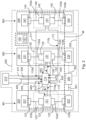
- FIG. 1 shows a schematic representation of a brake system according to a first exemplary embodiment.
- a vehicle 200 (in particular a commercial vehicle) is equipped with a brake system 100.
- the vehicle 200 has a brake value transmitter 210 and at least two axles 220, 230, each with at least two wheels 221, 222, 231, 232.
- the wheels 221, 222, 231, 232 can represent driven or non-driven wheels.
- the braking system 100 according to the first exemplary embodiment is designed as an electronically controlled braking system EBS for vehicles, in particular commercial vehicles.
- These commercial vehicles or vehicles preferably have a similar mass distribution M1, M2 on the front axle and rear axle. The mass M of the vehicles is therefore essentially not distributed unevenly.
- Such commercial vehicles 200 can represent coaches or trucks with a loading area or box body.
- the central control unit can also take into account an uneven axle load distribution.
- a failure of the central control unit then means that dynamic axle load-dependent braking force distribution can no longer be guaranteed.
- the failure of the dynamic axle load-dependent braking force distribution 470 can be tolerated.
- an axle modulator signal line 115 may be necessary, via which the axle modulators can ensure braking force distribution.
- the brake system 100 has a (single) central control unit 110.
- the central control unit 110 corresponds z. B. a central module in an electronic brake system EBS.
- the braking system 100 has a first and second axis modulator 120, 130.
- An axle modulator 120, 130, 140 is preferably provided for each axle 220, 230, 240 of the vehicle 200.
- the central control unit 110 receives a brake signal 211 from the brake value transmitter 210 of the vehicle 200.
- the brake signal 211 is also fed directly to the at least one first and second axle modulator 120, 130.
- the brake signal is provided by the brake value transmitter via several signal lines, each signal line being connected to an axle modulator. All signal lines are also connected to the central control unit.
- the axle modulators 120, 130 each have an axle control unit 121, 131 and brake modulators 122, 132 for each wheel which is arranged on the axle.
- the first axle modulator 120 receives a first brake signal 111 via line 110a and the second axle modulator 130 receives a second brake signal 112 via line 110b from the central control unit 110.
- a brake actuator 123a, 123b, 133a, 133b is provided in or on each wheel 221, 222, 231, 232 of the vehicle, which is controlled by the respective brake modulators 122, 132.
- a deceleration is determined by the central control unit 110 as a function of the brake signal 211 from the brake value transmitter 210 and as a function of vehicle stability programs and/or driver assistance systems.
- the vehicle stability programs and/or driver assistance systems can be implemented in the central control unit 110 or can be connected to the central control unit 110.
- the central control unit 110 then generates a brake signal 111, 112 for each of the axle modulators 120, 130.
- the axle modulators 120, 130 convert this braking information into signals for the respective brake actuators 123a, 123b, 133a, 133b using the brake modulators 122, 132.
- the axle modulators 120, 130 not only receive the first and second brake signals 111, 112 from the central control unit 110, but also directly the brake signal 211 from the brake value transmitter 210. This is done in order to provide safety redundancy, in particular in the event that the central control unit or the signal lines 110a, 110b are disturbed. If this case has occurred, then the axle modulators 120, 130 can appropriately control the respective brake actuators 123a, 123b, 133a, 133b via the brake modulators 122, 132 based on the brake signal 211 received directly from the brake value transmitter 210 in order to enable the vehicle to be braked .
- the brake actuators can be driven or operated hydraulically, pneumatically or electrically.
- the axle modulators can initiate a deceleration of the vehicle based on the brake signal 211 and optionally taking braking force distribution parameters into account.
- the axle modulators can cause the vehicle to decelerate even without the central control unit 110.
- this also means that the vehicle stability programs 410 and/or driver assistance systems 420 implemented or taken into account by the central control unit 110 cannot be taken into account.
- Each axle modulator 120, 130 is assigned to an axle 220, 230 of the vehicle 200.
- the axis modulators 120, 130 are preferably provided in, on or near the respective axis 220, 230.
- Each axle modulator 120, 130 has an axle control unit 121, 131, two brake modulators 122, 132 and electromechanical brake actuators 123a, 123b, 133a, 133b.
- the brake modulators optionally have electrical or electronic switching units for control and power transmission to the electromechanical brake actuators.
- a third signal line 115 is optionally provided between the first and second axis modulator 120, 130.
- the axle modulators 120, 130 could communicate with each other in order to be able to realize a desired deceleration of the vehicle.
- braking force distribution parameters be taken into account, but braking force distribution 470 can also take place depending on the situation with the aim of the best possible vehicle deceleration with the best possible driving stability. This is particularly beneficial for vehicles with an uneven weight distribution M1, M2.
- driver assistance systems 410 and vehicle stability systems 420 cannot be taken into account, since these are only processed or taken into account by the central control unit 110.
- the brake modulators 122, 132 output a brake modulation signal 122a, 132a to the brake actuators 123a, 123b, 133a, 133b, which causes the brake actuators 123, 133 to perform a desired deceleration or braking.
- the brake actuators 123a, 123b, 133a, 133b can be controlled electrically. This is advantageous because no further or additional intelligence needs to be present in the brake actuators or in the brake modulator. This is particularly advantageous with regard to the reliability of the brake modulators and the brake actuators. In particular, these have a lower susceptibility to vibrations as well as weather and temperature influences.
- the respective axle modulators 120, 130 optionally have the entire electronics necessary for determining the respective brake signals and controlling the brake actuators are needed. Since the axle modulators 120, 130 are provided in, on or near the axle 220, 230, they are less exposed to the effects of the weather than electronics that are integrated in or on the wheel.
- the brake system 100 also has an energy supply unit 150.
- This energy supply can be connected to an energy supply of the vehicle and has a predetermined storage option in order to be able to supply the braking system with energy in the event of a fault.
- the power supply unit 150 can have a plurality of rechargeable batteries 151.
- axle modulators 120, 130 and in particular the axle control unit 121, 131 are optionally suitable for carrying out an anti-lock braking system ABS control independently of the central control unit 110.
- the brake system 100 can have a redundant brake unit 300 (e.g. a pneumatic brake circuit), which operates independently of the central control unit 110 and, for example, enables at least emergency braking in the event of a fault in or on the central control unit 110.
- the brake unit 300 can be coupled to the axle modulators 120, 130, 140 via lines 301, 302, 303.
- the axis modulators can therefore have an additional connection for a redundant pneumatic brake circuit.
- the brake unit 300 can also be coupled directly to the brake modulators or the brake actuators.
- FIG. 2 shows a schematic representation of a brake system according to a second exemplary embodiment.
- the braking system according to the second exemplary embodiment essentially corresponds to the braking system according to the first exemplary embodiment, with the vehicle having three axles 220, 230, 240.
- the brake system according to the second exemplary embodiment therefore has three axle modulators 120, 130, 140.
- the structure of the respective axis modulators according to the second exemplary embodiment corresponds to the structure of the axis modulators according to the first exemplary embodiment.
- Any axis modulator thus receives a brake signal 111, 112, 113 from the central control unit 110 and a brake signal 211 from the brake value transmitter 210.
- the signal line 115 can extend between adjacent axle modulators 120, 130, 140, so that the axle modulators via the third signal line 115, in particular can communicate with each other in the event of an error.
Landscapes
- Engineering & Computer Science (AREA)
- Transportation (AREA)
- Mechanical Engineering (AREA)
- Regulating Braking Force (AREA)
- Valves And Accessory Devices For Braking Systems (AREA)
- Braking Systems And Boosters (AREA)
Description
- Die vorliegende Erfindung betrifft ein elektrisches Bremssystem für Fahrzeuge sowie ein Verfahren zum Steuern eines Bremssystems für Fahrzeuge.
- Bremssysteme für Fahrzeuge sind hinlänglich bekannt.
DE 10 2004 009 469 A1 beschreibt ein elektronisch gesteuertes elektromechanisches Bremssteuerungssystem für ein Nutzfahrzeug. Das Fahrzeug weist eine Vorderachse mit zwei Rädern, eine Hinterachse mit zwei Rädern und eine Betriebsbremse zum Abbremsen der Räder auf. Jedem der vier Räder ist ein Bremsaggregat zur Bremsbetätigung zugeordnet. Die Bremsaggregate sind elektrisch ansteuerbar. Ferner ist eine erste zentrale Steuereinrichtung vorgesehen zur Steuerung der Bremsaggregate. Des Weiteren ist eine zweite zentrale Steuereinrichtung als redundante Steuereinrichtung zur ersten Steuereinrichtung vorgesehen. Jeder Achse ist ein Achsmodulator zugeordnet, der aus einem Achsbremsbefehl von der zentralen Steuereinheit einen Radbremsbefehl für jedes Rad auf der ihm zugeordneten Achse ermittelt. In den zentralen Steuereinheiten erfolgt eine dynamische Anpassung der Bremsbefehle zur Fahrzeugstabilisierung. -
DE 10 2017 005 816 A1 zeigt ein Verfahren zur Bestimmung der durch Betätigung von Radbremsen erreichbaren Gesamtverzögerungswerte eines Nutzfahrzeugs oder einer Fahrzeugkombination mit mehreren Achsen. Sie betrifft außerdem eine Bremsanlage zur Durchführung des Verfahrens sowie ein Nutzfahrzeug oder eine Fahrzeugkombination mit einer solchen Bremsanlage zur Durchführung des Verfahrens. Um während der Fahrt die aktuell erreichbaren Gesamtverzögerungswerte zur Verzögerung eines Nutzfahrzeugs oder einer Fahrzeugkombination mit mehreren Achsen zu bestimmen, ist vorgesehen, dass zur Umsetzung einer Verzögerungsanforderung bei Teilbremsungen eine Bremskraftverteilung mit ungleich auf Bremseneinheiten mit den Radbremsen einer oder mehrerer Achsen verteilten Bremskräften erfolgt, wobei jeweils eine der Bremseneinheiten ausgewählt wird und über diese ausgewählte Bremseneinheit eine größere Bremskraft aufgebracht wird als über die anderen Bremseneinheiten, wobei eine aktuelle Verzögerung des Nutzfahrzeugs oder der Fahrzeugkombination gemessen oder ermittelt wird und als entsprechender Teilverzögerungswert der jeweils ausgewählten Bremseneinheit zugeordnet und abgespeichert wird. Die erreichbaren Gesamtverzögerungswerte werden als Summe der Teilverzögerungswerte der Bremseneinheiten bestimmt. - Zur Verbesserung von Fahrzeugbremssystemen wird ein Bremssystem mit einer reduzierten Komplexität gewünscht.
- Es ist daher eine Aufgabe der vorliegenden Erfindung, ein elektrisches Bremssystem für Fahrzeuge mit einer reduzierten Komplexität vorzusehen. Es ist insbesondere eine Aufgabe der vorliegenden Erfindung, ein elektrisches Bremssystem für Fahrzeuge mit reduzierten Kosten vorzusehen.
- Diese Aufgabe wird durch ein elektrisches Fahrzeugbremssystem nach Anspruch 1 sowie durch ein Verfahren zum Steuern eines elektrischen Fahrzeugbremssystems nach Anspruch 10 gelöst.
- Somit wird ein elektrisches Bremssystem für Fahrzeuge vorgesehen, welches einen Bremswertgeber, mindestens eine erste Achse mit mindestens zwei Rädern und eine zweite Achse mit mindestens zwei Rädern aufweist. Ein erster Achsmodulator ist der ersten Achse zugeordnet. Ein zweiter Achsmodulator ist der zweiten Achse zugeordnet. Ferner ist eine einzige zentrale Steuereinheit vorgesehen, die in Abhängigkeit von einem Bremssignal von dem Bremswertgeber oder in Abhängigkeit von einer weiteren Bremsanforderung (z. B. von Fahrerassistenzsystemen) über Datenverbindung der zentralen Steuereinheit mitgeteiltem Bremssignal ein erstes Bremssignal für den ersten Achsmodulator und ein zweites Bremssignal für den zweiten Achsmodulator erzeugt und auszugibt. Der erste und zweite Achsmodulator sind jeweils dazu ausgestaltet, die Räder der ersten und zweiten Achse in Abhängigkeit von dem ersten und zweiten Bremssignal von der zentralen Steuereinheit zu verzögern, wobei die Achsmodulatoren das Bremssignal von dem Bremswertgeber als Eingangssignal empfangen zusätzlich zu dem ersten oder zweiten Bremssignal von der zentralen Steuereinheit. Die Achsmodulatoren verwenden das Bremssignal von dem Bremswertgeber als Eingangssignal zur Erzeugung der Bremsmodulatorsignale, wenn ein Fehler in oder an der zentralen Steuereinheit auftritt.
- Damit wird ein elektrisches Fahrzeugbremssystem bzw. ein Bremssystem für Fahrzeuge mit lediglich einer einzigen zentralen Steuereinheit (Zentralmodul) vorgesehen. Jeder Achse des Fahrzeugs wird ein Achsmodulator zugeordnet, welches jeweils ein Bremssignal von der zentralen Steuereinheit empfängt und eine entsprechende Verzögerung auf die Räder der jeweiligen Achse initiiert. Der Achsmodulator weist mindestens einen Bremsmodulator für jedes der mit der Achse verbundenen Räder auf. Der Bremsmodulator wirkt auf einen Bremsaktuator, so dass die Räder abgebremst werden.
- Die zentrale Steuereinheit erhält ein Bremssignal von einem Bremswertgeber oder von einem dazu berechtigten System des Fahrzeugs. Die zentrale Steuereinheit wandelt das empfangene Bremssignal in Bremssignale für den ersten und zweiten Achsmodulator um, um das Fahrzeug verzögern bzw. abbremsen zu können. Der Achsmodulator empfängt das jeweilige Bremssignal von der zentralen Steuereinheit und wandelt das Bremssignal mittels der Bremsmodulatoren in ein Signal für die Bremsaktuatoren um.
- Gemäß einer bevorzugten Ausführungsform weist jeder Achsmodulator eine Achssteuereinheit und mindestens zwei Bremsmodulatoren Die Bremsmodulatoren erzeugen jeweils Bremsmodulatorsignale zur Steuerung der Bremsaktuatoren und geben diese an die Bremsaktuatoren aus, welche direkt an dem jeweiligen Rad vorgesehen sind.
- Demnach wird das Bremssignal von dem Bremswertgeber nicht nur an die zentrale Steuereinheit, sondern auch an jeden der Achsmodulatoren ausgegeben. Dadurch, dass die Achsmodulatoren das Bremssignal von dem Bremswertgeber empfangen, können die Achsmodulatoren auch bei Ausfall der zentralen Steuereinheit oder bei einem Fehler in der Leitung zwischen der zentralen Steuereinheit und den jeweiligen Achsmodulatoren ein redundantes Bremsen ermöglichen. Damit kann die Sicherheit des erfindungsgemäßen Bremssystems auch bei Reduzierung der Komplexität des Bremssystems und der damit einhergehenden Reduzierung der Kosten gewährleistet werden.
- Gemäß einer weiteren bevorzugten Ausführungsform ist mindestens eine Achsmodulatorsignalleitung zwischen mindestens zwei Achsmodulatoren vorgesehen. Diese dient der Kommunikation zwischen den Achsmodulatoren, insbesondere wenn ein Fehler in oder an der zentralen Steuereinheit vorhanden ist. Damit kann ein Ausgleich der Achsbremskräfte, der die Fahrzeugstabilität und die Bremsleistung verbessern kann, auch bei Ausfall der zentralen Steuereinheit erfolgen.
- Die Erfindung betrifft ebenfalls ein Fahrzeug, insbesondere Nutzfahrzeug, mit einem Bremswertgeber, mindestens einer ersten Achse mit mindestens zwei Rädern, einer zweiten Achse mit mindestens zwei Rädern, und mindestens einem oben beschriebenen elektrischen Bremssystem.
- Gemäß einer Ausführungsform ist die Masse des Fahrzeugs auf die erste und zweite Achse im Wesentlichen gleichmäßig verteilt. Alternativ dazu kann die Masse des Fahrzeugs auch ungleichmäßig auf die Achsen verteilt sein.
- Die Erfindung betrifft ebenfalls ein Verfahren zum Steuern eines erfindungsgemäßen elektrischen Bremssystems für Fahrzeuge.
- Während im Stand der Technik zwei zentrale und redundante zentrale Steuereinheiten in Form von Zentralmodulen des Bremssystems vorgesehen sind, kommt das erfindungsgemäße Bremssystem mit lediglich einer einzigen zentralen Steuereinheit aus. Die zentrale Steuereinheit fungiert als Zentralmodul des Bremssystems und dient zur Steuerung und Überwachung des elektrisch geregelten Bremssystems. Eine Sollverzögerung des Fahrzeugs wird aus einem Signal des Bremswertgebers ermittelt. Beispielsweise kann die Sollverzögerung zusammen mit den jeweiligen Radgeschwindigkeiten der Räder des Fahrzeugs als Eingangssignal für eine elektronische Regelung verwendet werden. Bei einem elektronisch geregelten pneumatischen Bremssystem ermittelt diese Regelung Drucksollwerte für das Bremssystem an der Vorderachse und an der Hinterachse. Für das elektrische Bremssystem ermittelt die Regelung elektrische Sollwerte, für die Ansteuerung der elektrischen Bremsaktuatoren. Die Sollwerte werden mit Istwerten verglichen und eine vorhandene Differenz kann ausgeregelt werden. Die zentrale Steuereinheit ist mit den Achsmodulen verbunden und tauscht Daten und insbesondere das jeweilige Bremssignal für die jeweiligen Achsmodulatoren aus.
- Gemäß einem Aspekt der vorliegenden Erfindung wird für jede Achse ein Achsmodulator vorgesehen. Der Achsmodulator stellt eine Achs-Steuereinheit dar. Der Achsmodulator kann optional pneumatische Druckregelkanäle aufweisen.
- Der Achsmodulator kann über einen zusätzlichen Anschluss für einen redundanten pneumatischen Bremskreis verfügen.
- Der Achsmodulator kann eine Steuereinheit oder ein Steuermodul aufweisen, welche eine Antiblockiersystem ABS-Steuerung der Räder ermöglichen, welche mit der Achse verbunden sind.
- Weitere Ausgestaltungen der Erfindung sind Gegenstand der Unteransprüche.
- Vorteile und Ausführungsbeispiele der Erfindung werden nachstehend unter Bezugnahme auf die Zeichnung näher erläutert.
- Figur 1
- zeigt eine schematische Darstellung eines Bremssystems gemäß einem ersten Ausführungsbeispiel und
- Figur 2
- zeigt eine schematische Darstellung eines Bremssystems gemäß einem zweiten Ausführungsbeispiel.
-
Figur 1 zeigt eine schematische Darstellung eines Bremssystems gemäß einem ersten Ausführungsbeispiel. Ein Fahrzeug 200 (insbesondere ein Nutzfahrzeug), ist mit einem Bremssystem 100. Das Fahrzeug 200 weist einen Bremswertgeber 210 und mindestens zwei Achsen 220, 230 jeweils mit mindestens zwei Rädern 221, 222, 231, 232 auf. Die Räder 221, 222, 231, 232 können angetriebene oder nicht angetriebene Räder darstellen. Das Bremssystem 100 gemäß dem ersten Ausführungsbeispiel ist als ein elektronisch geregeltes Bremssystem EBS für Fahrzeuge, insbesondere Nutzfahrzeuge, ausgestaltet. Diese Nutzfahrzeuge oder Fahrzeuge weisen vorzugsweise eine ähnliche Massenverteilung M1, M2 auf der Vorderachse und Hinterachse auf. Die Masse M der Fahrzeuge ist somit im Wesentlichen nicht ungleichmäßig verteilt. Derartige Nutzfahrzeuge 200 können Reisebusse oder Lastkraftwagen mit Ladefläche oder Kofferaufbau darstellen. - Die zentrale Steuereinheit kann gemäß einem Aspekt der Erfindung aber auch eine ungleichmäßige Achslastverteilung berücksichtigen. Ein Ausfall der zentralen Steuereinheit hat dann jedoch zur Folge, dass eine dynamische achslastabhängige Bremskraftverteilung nicht mehr gewährleistet werden kann. Bei Fahrzeuge mit typischerweise gleicher Achslastverteilung ist der Ausfall der dynamischen achslastabhängigen Bremskraftverteilung 470 jedoch zu verkraften. Für andere Fahrzeuge mit ungleichmäßiger Lastverteilung kann eine Achsmodulatorsignalleitung 115 notwendig sein, über die die Achsmodulatoren eine Bremskraftverteilung gewährleisten zu können.
- Das Bremssystem 100 weist eine (einzige) zentrale Steuereinheit 110 auf. Die zentrale Steuereinheit 110 entspricht z. B. einem Zentralmodul in einem elektronischen Bremssystem EBS. Das Bremssystem 100 weist einen ersten und zweiten Achsmodulator 120, 130 auf. Vorzugsweise wird für jede Achse 220, 230, 240 des Fahrzeugs 200 ein Achsmodulator 120, 130, 140 vorgesehen. Die zentrale Steuereinheit 110 erhält ein Bremssignal 211 von dem Bremswertgeber 210 des Fahrzeugs 200. Optional wird das Bremssignal 211 ebenfalls direkt dem mindestens einen ersten und zweiten Achsmodulator 120, 130 zugeführt. In einer bevorzugten Ausführungsform wird das Bremssignal vom Bremswertgeber über mehrere Signalleitungen zur Verfügung gestellt, wobei jede Signalleitung mit jeweils einem Achsmodulator verbunden ist. Alle Signalleitungen zusammen sind zudem ebenfalls mit dem zentralen Steuergerät verbunden.
- Die Achsmodulatoren 120, 130 weisen jeweils eine Achssteuereinheit 121, 131 sowie Bremsmodulatoren 122, 132 für jedes Rad auf, welches an der Achse angeordnet ist.
- Der erste Achsmodulator 120 empfängt ein erstes Bremssignal 111 über die Leitung 110a und der zweite Achsmodulator 130 empfängt ein zweites Bremssignal 112 über die Leitung 110b von der zentralen Steuereinheit 110.
- In oder an jedem Rad 221, 222, 231, 232 des Fahrzeugs ist ein Bremsaktuator 123a, 123b, 133a, 133b vorgesehen, der von den jeweiligen Bremsmodulatoren 122, 132 gesteuert wird.
- Für das elektronisch geregelte Bremssystem EBS wird eine Verzögerung von der zentralen Steuereinheit 110 in Abhängigkeit von dem Bremssignal 211 von dem Bremswertgeber 210 sowie in Abhängigkeit von Fahrzeugstabilitätsprogrammen und/oder Fahrerassistenzsystemen ermittelt. Die Fahrzeugstabilitätsprogramme und/oder Fahrerassistenzsysteme können in der zentralen Steuereinheit 110 realisiert werden oder mit der zentralen Steuereinheit 110 verbunden sein. Die zentrale Steuereinheit 110 erzeugt dann ein Bremssignal 111, 112 für jeden der Achsmodulatoren 120, 130. Die Achsmodulatoren 120, 130 wandeln diese Bremsinformationen mittels der Bremsmodulatoren 122, 132 in Signale für die jeweiligen Bremsaktuatoren 123a, 123b, 133a, 133b um.
- Die Achsmodulatoren 120, 130 empfangen nicht nur das erste und zweite Bremssignal 111, 112 von der zentralen Steuereinheit 110, sondern auch direkt das Bremssignal 211 von dem Bremswertgeber 210. Dies erfolgt, um eine Sicherheitsredundanz vorzusehen, insbesondere für den Fall, dass die zentrale Steuereinheit oder die Signalleitungen 110a, 110b gestört sind. Falls dieser Fall eingetreten ist, dann können die Achsmodulatoren 120, 130 basierend auf dem direkt von dem Bremswertgeber 210 empfangenen Bremssignal 211 über die Bremsmodulatoren 122, 132 die jeweiligen Bremsaktuatoren 123a, 123b, 133a, 133b entsprechend ansteuern, um ein Abbremsen des Fahrzeugs zu ermöglichen.
- Die Bremsaktuatoren können hydraulisch, pneumatisch oder elektrisch angetrieben bzw. betätigt werden.
- Wenn in einem Fehlerfall die zentrale Steuereinheit 110 und/oder die Signalleitungen 110a, 110b fehlerhaft sind, dann können die Achsmodulatoren basierend auf dem Bremssignal 211 und optional unter Berücksichtigung von Bremskraftverteilungsparametern eine Verzögerung des Fahrzeugs initiieren.
- Bei einem Fehlerfall (Defekt der zentralen Steuereinheit 110 oder der Signalleitung 11 0a, 110b) können die Achsmodulatoren eine Verzögerung des Fahrzeugs auch ohne die zentrale Steuereinheit 110 bewirken. Dies bedeutet dann aber auch, dass die von der zentralen Steuereinheit 110 realisierten bzw. mitberücksichtigten Fahrzeugstabilitätsprogramme 410 und/oder Fahrerassistenzsysteme 420 nicht mitberücksichtigt werden können.
- Jeder Achsmodulator 120, 130 ist einer Achse 220, 230 des Fahrzeugs 200 zugeordnet. Vorzugsweise sind die Achsmodulatoren 120, 130 in, an oder in der Nähe der jeweiligen Achse 220, 230 vorgesehen. Jeder Achsmodulator 120, 130 weist eine Achssteuereinheit 121,131 zwei Bremsmodulatoren 122, 132 und elektromechanische Bremsaktuatoren 123a, 123b, 133a, 133b auf. Die Bremsmodulatoren weisen optional elektrische oder elektronische Schalteinheiten zur Ansteuerung und zur Leistungsübertragung an die elektromechanischen Bremsaktuatoren auf.
- Gemäß einem Aspekt der vorliegenden Erfindung ist optional eine dritte Signalleitung 115 zwischen dem ersten und zweiten Achsmodulator 120, 130 vorgesehen. Bei einem Fehlerfall 430 (Ausfall der zentralen Steuereinheit 110) könnten damit die Achsmodulatoren 120, 130 miteinander kommunizieren, um eine gewünschte Verzögerung des Fahrzeugs realisieren zu können. Hierbei können nicht nur Bremskraftverteilungsparameter mitberücksichtigt werden, sondern es kann auch situationsabhängig eine Bremskraftverteilung 470 mit dem Ziel der bestmöglichen Fahrzeugverzögerung bei bestmöglicher Fahrstabilität stattfinden. Insbesondere bei Fahrzeugen mit einer ungleichmäßigen Gewichtsverteilung M1, M2 ist dies zuträglich. In einem derartigen Fehlerfall 430 können Fahrerassistenzsysteme 410 und Fahrzeugstabilitätssysteme 420 nicht mitberücksichtigt werden, da diese nur von der zentralen Steuereinheit 110 bearbeitet bzw. mitberücksichtigt werden.
- Die Bremsmodulatoren 122, 132 geben ein Bremsmodulationssignal 122a, 132a an die Bremsaktuatoren 123a, 123b, 133a, 133b aus, welches die Bremsaktuatoren 123, 133 veranlasst, eine gewünschte Verzögerung oder ein gewünschtes Abbremsen durchzuführen.
- Gemäß einem Aspekt der vorliegenden Erfindung können die Bremsaktuatoren 123a, 123b, 133a, 133b elektrisch angesteuert werden. Dies ist vorteilhaft, weil in den Bremsaktuatoren sowie in dem Bremsmodulator keine weitergehende bzw. zusätzliche Intelligenz vorhanden sein muss. Dies ist insbesondere vorteilhaft im Hinblick auf die Zuverlässigkeit der Bremsmodulatoren und der Bremsaktuatoren. Insbesondere weisen diese eine geringere Anfälligkeit gegen Erschütterungen sowie Witterungseinflüsse und Temperatureinflüsse auf.
- Gemäß einem Aspekt der vorliegenden Erfindung weisen die jeweiligen Achsmodulatoren 120, 130 optional die gesamte Elektronik auf, welche für die Bestimmung der jeweiligen Bremssignale und die Ansteuerung der Bremsaktuatoren benötigt werden. Da die Achsmodulatoren 120, 130 in, an oder in der Nähe der Achse 220, 230 vorgesehen sind, sind diese den Witterungseinflüssen weniger ausgesetzt als Elektronik, welche in oder an dem Rad integriert ist.
- Das Bremssystem 100 weist ferner eine Energieversorgungseinheit 150 auf. Diese Energieversorgung kann mit einer Energieversorgung des Fahrzeugs verbunden sein und weist eine vorab festgelegte Speichermöglichkeit auf, um das Bremssystem in einem Fehlerfall noch mit Energie versorgen zu können. Insbesondere kann die Energieversorgungseinheit 150 eine Mehrzahl von wiederaufladbaren Akkumulatoren 151 aufweisen.
- Die Achsmodulatoren 120, 130 und insbesondere die Achssteuereinheit 121, 131 sind optional dazu geeignet, eine Antiblockiersystem ABS-Regelung unabhängig von der zentralen Steuereinheit 110 durchzuführen.
- Optional kann das Bremssystem 100 eine redundante Bremseinheit 300 (z.B. ein pneumatischen Bremskreis) aufweisen, die unabhängig von der zentralen Steuereinheit 110 arbeitet und z.B. bei einem Fehler in oder an der zentralen Steuereinheit 110 zumindest eine Notbremsung ermöglicht. Dazu kann die Bremseinheit 300 über Leitungen 301, 302, 303 mit den Achsmodulatoren 120, 130, 140 gekoppelt sein. Die Achsmodulatoren können daher über einen zusätzlichen Anschluss für einen redundanten pneumatischen Bremskreis verfügen. Alternativ dazu kann die Bremseinheit 300 auch direkt mit den Bremsmodulatoren oder den Bremsaktuatoren gekoppelt sein.
-
Figur 2 zeigt eine schematische Darstellung eines Bremssystems gemäß einem zweiten Ausführungsbeispiel. Das Bremssystem gemäß dem zweiten Ausführungsbeispiel entspricht im Wesentlichen dem Bremssystem gemäß dem ersten Ausführungsbeispiel, wobei das Fahrzeug drei Achsen 220, 230, 240 aufweist. Damit weist das Bremssystem gemäß dem zweiten Ausführungsbeispiel drei Achsmodulatoren 120, 130, 140 auf. Der Aufbau der jeweiligen Achsmodulatoren gemäß dem zweiten Ausführungsbeispiel entspricht dem Aufbau der Achsmodulatoren gemäß dem ersten Ausführungsbeispiel. Jeder Achsmodulator empfängt somit ein Bremssignal 111, 112, 113 von der zentralen Steuereinheit 110 sowie ein Bremssignal 211 von dem Bremswertgeber 210. Optional kann die Signalleitung 115 sich zwischen benachbarten Achsmodulatoren 120, 130, 140 erstrecken, so dass die Achsmodulatoren über die dritte Signalleitung 115 insbesondere in einem Fehlerfall miteinander kommunizieren können. -
- 100
- Bremssystem
- 110
- zentrale Steuereinheit
- 111
- erstes Bremssignal
- 112
- zweites Bremssignal
- 110a
- erste Signalleitung
- 110b
- zweite Signalleitung
- 110c
- dritte Signalleitung
- 115
- Achsmodulatorsignalleitung
- 120
- erster Achsmodulator
- 121
- Achssteuereinheit
- 122
- Bremsmodulator
- 122a
- Bremsmodulatorsignal
- 123a
- Bremsaktuator
- 123b
- Bremsaktuator
- 130
- zweiter Achsmodulator
- 131
- Achssteuereinheit
- 132
- Bremsmodulator
- 132a
- Bremsmodulatorsignal
- 133a
- Bremsaktuator
- 133b
- Bremsaktuator
- 140
- dritter Achsmodulator
- 141
- Achssteuereinheit
- 142
- Bremsmodulation
- 142a
- Bremsmodulatorsignal
- 143a
- Bremsaktuator
- 143b
- Bremsaktuator
- 150
- Energieversorgungseinheit
- 151
- wiederaufladbarer Akkumulator
- 200
- Fahrzeug
- 210
- Bremswertgeber
- 211
- Bremssignal
- 220
- erste Achse
- 221
- Rad
- 222
- Rad
- 230
- zweite Achse
- 231
- Rad
- 232
- Rad
- 240
- dritte Achse
- 241
- Rad
- 242
- Rad
- 300
- Bremseinheit
- 400
- weitere Bremsanforderung
- 410
- Fahrstabilitätsprogram
- 420
- Fahrassistenzprogram
- 430
- Fehler
- 440
- Bremskraftverteilung
- 450
- Notbremsanforderung
- 460
- Bremskraftverteilungsparameter
- 470
- Bremskraftverteilung
- M
- Masse
- M1, M2
- Masseverteilung
- ABS
- Antiblockiersystem
Claims (10)
- Elektrisches Bremssystem (100) für Fahrzeuge (200), das einen Bremswertgeber (210), mindestens eine erste Achse (220) mit mindestens zwei Rädern (221, 222) und eine zweite Achse (230) mit mindestens zwei Rädern (231, 232) aufweist, miteinem ersten Achsmodulator (120), welcher der ersten Achse (220) zugeordnet ist und mindestens einem zweiten Achsmodulator (130), welcher der zweiten Achse (230) zugeordnet ist,einer einzigen zentralen Steuereinheit (110), welche dazu ausgestaltet ist, in Abhängigkeit von einem Bremssignal (211) von dem Bremswertgeber (210) oder in Abhängigkeit von einer weiteren Bremsanforderung (400) ein erstes Bremssignal (111) für den ersten Achsmodulator (120) und ein zweites Bremssignal (112) für den zweiten Achsmodulator (130) zu erzeugen und auszugeben,wobei der erste und zweite Achsmodulator (120, 130) jeweils dazu ausgestaltet sind, die Räder (221, 222; 231, 232) der ersten und zweiten Achse (220, 230) über Bremsmodulatorsignale (122a, 132a, 142a) in Abhängigkeit von dem ersten und zweiten Bremssignal (111, 112) von der zentralen Steuereinheit (110) zu verzögern,dadurch gekennzeichnet, dassdie Achsmodulatoren (120, 130, 140) das Bremssignal (211) von dem Bremswertgeber (210) als Eingangssignal zusätzlich zu dem ersten oder zweiten Bremssignal (111, 112, 113) von der zentralen Steuereinheit (110) empfangen und jeweils dazu ausgestaltet sind, bei einem Fehler (430) in oder an der zentralen Steuereinheit (110) das Bremssignal (211) von dem Bremswertgeber (210) als Eingangssignal zur Erzeugung der Bremsmodulatorsignale (122a, 132a, 142a) zu verwenden.
- Elektrisches Bremssystem (100) für Fahrzeuge (200) nach Anspruch 1, wobeijeder Achsmodulator (120, 130, 140) eine Achssteuereinheit (121, 131, 141), und mindestens zwei Bremsmodulatoren (122, 132, 142) aufweist,wobei die Bremsmodulatoren (122, 132, 142) jeweils Bremsmodulatorsignale (122a, 132a, 142a) zur Steuerung von Bremsaktuatoren (123, 133, 143) erzeugen und an die Bremsaktuatoren (123, 133, 143) ausgeben.
- Elektrisches Bremssystem (100) für Fahrzeuge (200) nach Anspruch 1 oder 2, ferner mitmindestens einer Achsmodulatorsignalleitung (115) zwischen mindestens zwei Achsmodulatoren (120, 130, 140),wobei die mindestens eine Achsmodulatorsignalleitung (115) einer Kommunikation zwischen den Achsmodulatoren (120, 130, 140) insbesondere bei einem Fehler (430) in oder an der zentralen Steuereinheit (110) dient.
- Elektrisches Bremssystem (100) für Fahrzeuge (200) nach einem der Ansprüche 1 bis 3, wobei
die zentrale Steuereinheit (110) dazu ausgestaltet ist, die weitere Bremsanforderungen in Form von Fahrzeugstabilitätsprogramme (410) und/oder Fahrassistenzprogramme (420) bei der Erzeugung des ersten und zweiten Bremssignal (111, 112) mit zu berücksichtigen. - Elektrisches Bremssystem (100) für Fahrzeuge (200) nach einem der Ansprüche 1 bis 4, wobei
die Achsmodulatoren (120, 130, 140) jeweils dazu ausgestaltet sind, eine Antiblockier-Steuerung (ABS) durchzuführen. - Elektrisches Bremssystem (100) für Fahrzeuge (200) nach einem der Ansprüche 1 bis 4, wobei
die weitere Bremsanforderung (400) eine Notbremsanforderung (450) darstellt. - Elektrisches Bremssystem (100) für Fahrzeuge (200) nach einem der Ansprüche 1 bis 6, wobei
die zentrale Steuereinheit (110) in einem der Achsmodulatoren (120, 130, 140) integriert ist. - Fahrzeug (200), insbesondere Nutzfahrzeug (200), miteinem Bremswertgeber (210),mindestens einer ersten Achse (220) mit mindestens zwei Rädern (221, 222),einer zweiten Achse (230) mit mindestens zwei Rädern (231, 232), undmindestens einem elektrischen Bremssystem (100) nach einem der Ansprüche 1 bis 7.
- Fahrzeug (200) nach Anspruch 8, wobei
eine Massenverteilung (M1, M2) einer Masse (M) des Fahrzeugs (200) auf die erste und zweite Achse (120, 130) im Wesentlichen gleichmäßig ist oder über Bremskraftverteilungsparameter (460) eine Bremskraftverteilung (470) entsprechend einer ungleichmäßigen Gewichtsverteilung (M1, M2) eingestellt werden kann oder über eine Achsmodulsignalleitung (115) eine Bremskraftverteilung (470) situationsabhängig zwischen dem mindestens ersten und zweiten Achsmodulatoren (120, 130, 140) vorgesehen werden kann. - Verfahren zum Steuern eines elektrischen Bremssystems (100) nach einem der Ansprüch 1 bis 7 für Fahrzeuge (200), mit den Schritten:Erzeugen eines ersten Bremssignals (111) für den ersten Achsmodulator (120) und eines zweiten Bremssignal (112) für den zweiten Achsmodulator (130) in Abhängigkeit von einem Bremssignal (211) von dem Bremswertgeber (210) durch eine einzige zentrale Steuereinheit (110), wobei bei einem Fehler (430) in oder an der zentralen Steuereinheit (110) das Bremssignal (211) von dem Bremswertgeber (210) als Eingangssignal für die Achsmodulatoren (120, 130) verwendet wird, undVerzögern der Räder (221, 222; 231, 232) der ersten und zweiten Achse (220, 230) in Abhängigkeit vom dem ersten und zweiten Bremssignal (111, 112) von der zentralen Steuereinheit (110) oder in Abhängigkeit vom Bremssignal (211) des Bremswertgebers (210).
Applications Claiming Priority (2)
| Application Number | Priority Date | Filing Date | Title |
|---|---|---|---|
| DE102019130233.1A DE102019130233A1 (de) | 2019-11-08 | 2019-11-08 | Elektrisches Bremssystem für Fahrzeuge |
| PCT/EP2020/080634 WO2021089458A1 (de) | 2019-11-08 | 2020-11-02 | Elektrisches bremssystem für fahrzeuge |
Publications (2)
| Publication Number | Publication Date |
|---|---|
| EP4054908A1 EP4054908A1 (de) | 2022-09-14 |
| EP4054908B1 true EP4054908B1 (de) | 2023-11-22 |
Family
ID=73043271
Family Applications (1)
| Application Number | Title | Priority Date | Filing Date |
|---|---|---|---|
| EP20800634.6A Active EP4054908B1 (de) | 2019-11-08 | 2020-11-02 | Elektrisches bremssystem für fahrzeuge |
Country Status (5)
| Country | Link |
|---|---|
| US (1) | US12139127B2 (de) |
| EP (1) | EP4054908B1 (de) |
| CN (1) | CN114599560B (de) |
| DE (1) | DE102019130233A1 (de) |
| WO (1) | WO2021089458A1 (de) |
Families Citing this family (1)
| Publication number | Priority date | Publication date | Assignee | Title |
|---|---|---|---|---|
| DE102019129305A1 (de) * | 2019-10-30 | 2021-05-06 | Knorr-Bremse Systeme für Nutzfahrzeuge GmbH | Schaltvorrichtung für ein Bremssystem für ein Fahrzeug, Bremssystem mit einer Schaltvorrichtung und Verfahren zum Betreiben einer Schaltvorrichtung |
Family Cites Families (9)
| Publication number | Priority date | Publication date | Assignee | Title |
|---|---|---|---|---|
| DE102004009469A1 (de) | 2004-02-27 | 2005-09-15 | Daimlerchrysler Ag | Redundantes Bremssteuerungssystem für ein Fahrzeug |
| DE102008061944B4 (de) * | 2008-12-12 | 2024-03-14 | Zf Cv Systems Hannover Gmbh | Bremssteuergerät für ein Bremssystem eines Nutzfahrzeugs |
| DE102014006613A1 (de) * | 2014-05-08 | 2015-11-12 | Wabco Gmbh | Steuergerät für ein druckluftbetriebenes Bremssystem, Bremssystem mit derartigem Steuergerät sowie Fahrzeug mit derartigem Bremssystem |
| DE102014011422A1 (de) | 2014-07-31 | 2016-02-04 | Wabco Gmbh | Bremsdruckmodulator eines elektronischen Bremssystems eines Nutzfahrzeugs |
| DE102015011296A1 (de) | 2015-09-02 | 2017-03-02 | Wabco Gmbh | Elektronisch steuerbares pneumatisches Bremssystem in einem Nutzfahrzeug sowie Verfahren zum elektronischen Steuern eines pneumatischen Bremssystems |
| DE102016010463A1 (de) * | 2016-08-31 | 2018-03-01 | Wabco Gmbh | Verfahren zum elektronischen Steuern eines pneumatischen Bremssystems in einem Fahrzeug, insbesondere Nutzfahrzeug, sowie elektronisch steuerbares pneumatisches Bremssystem |
| DE102017005816A1 (de) * | 2017-06-20 | 2018-12-20 | Wabco Gmbh | Verfahren zur Bestimmung der durch Betätigung von Radbremsen erreichbaren Gesamtverzögerungswerten eines Nutzfahrzeugs, Bremsanlage zur Durchführung des Verfahrens sowie Nutzfahrzeug damit |
| DE102017007788A1 (de) | 2017-08-17 | 2019-02-21 | Wabco Gmbh | Verfahren zur Verzögerung eines Fahrzeuges, insbesondere eines Nutzfahrzeuges, sowie ein elektropneumatisches Bremssystem zur Durchführung des Verfahrens und Fahrzeug mit einem elektropneumatischen Bremssystem |
| DE102018126094A1 (de) * | 2018-10-19 | 2020-04-23 | Wabco Gmbh | Aktuatormodul für ein Bremssystem eines Fahrzeugs |
-
2019
- 2019-11-08 DE DE102019130233.1A patent/DE102019130233A1/de active Pending
-
2020
- 2020-11-02 EP EP20800634.6A patent/EP4054908B1/de active Active
- 2020-11-02 WO PCT/EP2020/080634 patent/WO2021089458A1/de not_active Ceased
- 2020-11-02 CN CN202080075625.8A patent/CN114599560B/zh active Active
-
2022
- 2022-04-14 US US17/721,128 patent/US12139127B2/en active Active
Also Published As
| Publication number | Publication date |
|---|---|
| CN114599560A (zh) | 2022-06-07 |
| US20220234558A1 (en) | 2022-07-28 |
| DE102019130233A1 (de) | 2021-05-12 |
| WO2021089458A1 (de) | 2021-05-14 |
| CN114599560B (zh) | 2025-04-04 |
| US12139127B2 (en) | 2024-11-12 |
| EP4054908A1 (de) | 2022-09-14 |
Similar Documents
| Publication | Publication Date | Title |
|---|---|---|
| EP4048565B1 (de) | Bremssystem für ein kraftfahrzeug | |
| EP3938257B1 (de) | Elektronisch steuerbares bremssystem mit zwei rückfallebenen | |
| EP3938256B1 (de) | Elektronisch steuerbares bremssystem mit zwei rückfallebenen | |
| EP3529118B2 (de) | System mit getrennten steuereinheiten für die stelleinheiten einer elektrischen parkbremse | |
| EP3529117B2 (de) | System mit getrennten steuereinheiten für die stelleinheiten einer elektrischen parkbremse | |
| EP3562719B1 (de) | Kraftfahrzeug-steuergerät für eine elektrische parkbremse | |
| EP0780276B1 (de) | Bremsanlage für ein Kraftfahrzeug | |
| EP1541437B1 (de) | Elektronisches Bremssystem für ein Fahrzeug | |
| EP2942249B2 (de) | Druckmittelbetriebenes bremssystem für ein kraftfahrzeug sowie kraftfahrzeug damit | |
| DE102009046238C5 (de) | Elektrisches Bremssystem, insbesondere elektromechanisches Bremssystem | |
| DE102009030816A1 (de) | Vorrichtung und Verfahren zur Regelung einer Fahrdynamik | |
| EP2183136A1 (de) | Bremssystem für ein fahrzeug und ein verfahren zum betreiben eines bremssystems für ein fahrzeug | |
| DE19937159B4 (de) | Elektrisch gesteuertes Bremssystem | |
| EP3784537B1 (de) | Bremssysteme für ein fahrzeug und verfahren zum autonomen abbremsen eines fahrzeugs | |
| DE102009046234A1 (de) | Elektrisches Bremssystem, insbesondere elektromechanisches Bremssystem, Verfahren zum Betreiben eines elektrischen Bremssystems | |
| DE102007056146A1 (de) | Bremsanlage für ein Schienenfahrzeug und Verfahren zum Abbremsen des Schienenfahrzeugs und Bremssteuerung für eine derartige Bremsanlage | |
| DE102023122197A1 (de) | Dezentrales Steuersystem für eine Kraftfahrzeug-Bremsanlage, Kraftfahrzeug-Bremsanlage und Kraftfahrzeug | |
| EP4377170B1 (de) | Redundantes elektromechanisches bremssystem sowie aktuator dafür | |
| DE102020003455A1 (de) | Bremssystem für ein Fahrzeug | |
| DE10011634C1 (de) | Verfahren zur Leistungsansteuerung von elektromechanischen Bremssystemen in Kraftfahrzeugen | |
| WO2023208376A1 (de) | Elektromechanisches bremssystem und fahrzeug, insbesondere nutzfahrzeug | |
| EP4054908A1 (de) | Elektrisches bremssystem für fahrzeuge | |
| DE102020209658A1 (de) | Bremseinrichtung für ein Fahrzeug und Verfahren zum Betreiben einer Bremseinrichtung | |
| DE102024200198A1 (de) | Verfahren zur Zuordnung von radindividuellen Radbremsen zu einer Fahrzeugachse sowie Bremssystem | |
| DE102024200854A1 (de) | Verfahren zum Steuern eines Bremssystems in einem Notfallmodus bei einer Störung sowie Bremssystem |
Legal Events
| Date | Code | Title | Description |
|---|---|---|---|
| STAA | Information on the status of an ep patent application or granted ep patent |
Free format text: STATUS: UNKNOWN |
|
| STAA | Information on the status of an ep patent application or granted ep patent |
Free format text: STATUS: THE INTERNATIONAL PUBLICATION HAS BEEN MADE |
|
| PUAI | Public reference made under article 153(3) epc to a published international application that has entered the european phase |
Free format text: ORIGINAL CODE: 0009012 |
|
| STAA | Information on the status of an ep patent application or granted ep patent |
Free format text: STATUS: REQUEST FOR EXAMINATION WAS MADE |
|
| 17P | Request for examination filed |
Effective date: 20220608 |
|
| AK | Designated contracting states |
Kind code of ref document: A1 Designated state(s): AL AT BE BG CH CY CZ DE DK EE ES FI FR GB GR HR HU IE IS IT LI LT LU LV MC MK MT NL NO PL PT RO RS SE SI SK SM TR |
|
| DAV | Request for validation of the european patent (deleted) | ||
| DAX | Request for extension of the european patent (deleted) | ||
| REG | Reference to a national code |
Ref country code: DE Ref legal event code: R079 Ref document number: 502020006152 Country of ref document: DE Free format text: PREVIOUS MAIN CLASS: B60T0013660000 Ipc: B60T0008175500 Ref country code: DE Ref legal event code: R079 Free format text: PREVIOUS MAIN CLASS: B60T0013660000 Ipc: B60T0008175500 |
|
| GRAP | Despatch of communication of intention to grant a patent |
Free format text: ORIGINAL CODE: EPIDOSNIGR1 |
|
| RIC1 | Information provided on ipc code assigned before grant |
Ipc: B60T 8/1755 20060101AFI20230605BHEP |
|
| STAA | Information on the status of an ep patent application or granted ep patent |
Free format text: STATUS: GRANT OF PATENT IS INTENDED |
|
| INTG | Intention to grant announced |
Effective date: 20230713 |
|
| GRAS | Grant fee paid |
Free format text: ORIGINAL CODE: EPIDOSNIGR3 |
|
| GRAJ | Information related to disapproval of communication of intention to grant by the applicant or resumption of examination proceedings by the epo deleted |
Free format text: ORIGINAL CODE: EPIDOSDIGR1 |
|
| GRAL | Information related to payment of fee for publishing/printing deleted |
Free format text: ORIGINAL CODE: EPIDOSDIGR3 |
|
| STAA | Information on the status of an ep patent application or granted ep patent |
Free format text: STATUS: REQUEST FOR EXAMINATION WAS MADE |
|
| GRAP | Despatch of communication of intention to grant a patent |
Free format text: ORIGINAL CODE: EPIDOSNIGR1 |
|
| STAA | Information on the status of an ep patent application or granted ep patent |
Free format text: STATUS: GRANT OF PATENT IS INTENDED |
|
| INTC | Intention to grant announced (deleted) | ||
| INTG | Intention to grant announced |
Effective date: 20230919 |
|
| GRAA | (expected) grant |
Free format text: ORIGINAL CODE: 0009210 |
|
| STAA | Information on the status of an ep patent application or granted ep patent |
Free format text: STATUS: THE PATENT HAS BEEN GRANTED |
|
| AK | Designated contracting states |
Kind code of ref document: B1 Designated state(s): AL AT BE BG CH CY CZ DE DK EE ES FI FR GB GR HR HU IE IS IT LI LT LU LV MC MK MT NL NO PL PT RO RS SE SI SK SM TR |
|
| REG | Reference to a national code |
Ref country code: GB Ref legal event code: FG4D Free format text: NOT ENGLISH |
|
| REG | Reference to a national code |
Ref country code: CH Ref legal event code: EP |
|
| REG | Reference to a national code |
Ref country code: DE Ref legal event code: R096 Ref document number: 502020006152 Country of ref document: DE |
|
| REG | Reference to a national code |
Ref country code: IE Ref legal event code: FG4D Free format text: LANGUAGE OF EP DOCUMENT: GERMAN |
|
| REG | Reference to a national code |
Ref country code: LT Ref legal event code: MG9D |
|
| REG | Reference to a national code |
Ref country code: NL Ref legal event code: MP Effective date: 20231122 |
|
| PG25 | Lapsed in a contracting state [announced via postgrant information from national office to epo] |
Ref country code: GR Free format text: LAPSE BECAUSE OF FAILURE TO SUBMIT A TRANSLATION OF THE DESCRIPTION OR TO PAY THE FEE WITHIN THE PRESCRIBED TIME-LIMIT Effective date: 20240223 |
|
| PG25 | Lapsed in a contracting state [announced via postgrant information from national office to epo] |
Ref country code: IS Free format text: LAPSE BECAUSE OF FAILURE TO SUBMIT A TRANSLATION OF THE DESCRIPTION OR TO PAY THE FEE WITHIN THE PRESCRIBED TIME-LIMIT Effective date: 20240322 |
|
| PG25 | Lapsed in a contracting state [announced via postgrant information from national office to epo] |
Ref country code: LT Free format text: LAPSE BECAUSE OF FAILURE TO SUBMIT A TRANSLATION OF THE DESCRIPTION OR TO PAY THE FEE WITHIN THE PRESCRIBED TIME-LIMIT Effective date: 20231122 |
|
| PG25 | Lapsed in a contracting state [announced via postgrant information from national office to epo] |
Ref country code: NL Free format text: LAPSE BECAUSE OF FAILURE TO SUBMIT A TRANSLATION OF THE DESCRIPTION OR TO PAY THE FEE WITHIN THE PRESCRIBED TIME-LIMIT Effective date: 20231122 |
|
| PG25 | Lapsed in a contracting state [announced via postgrant information from national office to epo] |
Ref country code: ES Free format text: LAPSE BECAUSE OF FAILURE TO SUBMIT A TRANSLATION OF THE DESCRIPTION OR TO PAY THE FEE WITHIN THE PRESCRIBED TIME-LIMIT Effective date: 20231122 |
|
| PG25 | Lapsed in a contracting state [announced via postgrant information from national office to epo] |
Ref country code: NL Free format text: LAPSE BECAUSE OF FAILURE TO SUBMIT A TRANSLATION OF THE DESCRIPTION OR TO PAY THE FEE WITHIN THE PRESCRIBED TIME-LIMIT Effective date: 20231122 Ref country code: LT Free format text: LAPSE BECAUSE OF FAILURE TO SUBMIT A TRANSLATION OF THE DESCRIPTION OR TO PAY THE FEE WITHIN THE PRESCRIBED TIME-LIMIT Effective date: 20231122 Ref country code: IS Free format text: LAPSE BECAUSE OF FAILURE TO SUBMIT A TRANSLATION OF THE DESCRIPTION OR TO PAY THE FEE WITHIN THE PRESCRIBED TIME-LIMIT Effective date: 20240322 Ref country code: GR Free format text: LAPSE BECAUSE OF FAILURE TO SUBMIT A TRANSLATION OF THE DESCRIPTION OR TO PAY THE FEE WITHIN THE PRESCRIBED TIME-LIMIT Effective date: 20240223 Ref country code: ES Free format text: LAPSE BECAUSE OF FAILURE TO SUBMIT A TRANSLATION OF THE DESCRIPTION OR TO PAY THE FEE WITHIN THE PRESCRIBED TIME-LIMIT Effective date: 20231122 Ref country code: BG Free format text: LAPSE BECAUSE OF FAILURE TO SUBMIT A TRANSLATION OF THE DESCRIPTION OR TO PAY THE FEE WITHIN THE PRESCRIBED TIME-LIMIT Effective date: 20240222 Ref country code: PT Free format text: LAPSE BECAUSE OF FAILURE TO SUBMIT A TRANSLATION OF THE DESCRIPTION OR TO PAY THE FEE WITHIN THE PRESCRIBED TIME-LIMIT Effective date: 20240322 |
|
| PG25 | Lapsed in a contracting state [announced via postgrant information from national office to epo] |
Ref country code: SE Free format text: LAPSE BECAUSE OF FAILURE TO SUBMIT A TRANSLATION OF THE DESCRIPTION OR TO PAY THE FEE WITHIN THE PRESCRIBED TIME-LIMIT Effective date: 20231122 Ref country code: RS Free format text: LAPSE BECAUSE OF FAILURE TO SUBMIT A TRANSLATION OF THE DESCRIPTION OR TO PAY THE FEE WITHIN THE PRESCRIBED TIME-LIMIT Effective date: 20231122 Ref country code: PL Free format text: LAPSE BECAUSE OF FAILURE TO SUBMIT A TRANSLATION OF THE DESCRIPTION OR TO PAY THE FEE WITHIN THE PRESCRIBED TIME-LIMIT Effective date: 20231122 Ref country code: NO Free format text: LAPSE BECAUSE OF FAILURE TO SUBMIT A TRANSLATION OF THE DESCRIPTION OR TO PAY THE FEE WITHIN THE PRESCRIBED TIME-LIMIT Effective date: 20240222 Ref country code: LV Free format text: LAPSE BECAUSE OF FAILURE TO SUBMIT A TRANSLATION OF THE DESCRIPTION OR TO PAY THE FEE WITHIN THE PRESCRIBED TIME-LIMIT Effective date: 20231122 Ref country code: HR Free format text: LAPSE BECAUSE OF FAILURE TO SUBMIT A TRANSLATION OF THE DESCRIPTION OR TO PAY THE FEE WITHIN THE PRESCRIBED TIME-LIMIT Effective date: 20231122 |
|
| PG25 | Lapsed in a contracting state [announced via postgrant information from national office to epo] |
Ref country code: DK Free format text: LAPSE BECAUSE OF FAILURE TO SUBMIT A TRANSLATION OF THE DESCRIPTION OR TO PAY THE FEE WITHIN THE PRESCRIBED TIME-LIMIT Effective date: 20231122 |
|
| PG25 | Lapsed in a contracting state [announced via postgrant information from national office to epo] |
Ref country code: CZ Free format text: LAPSE BECAUSE OF FAILURE TO SUBMIT A TRANSLATION OF THE DESCRIPTION OR TO PAY THE FEE WITHIN THE PRESCRIBED TIME-LIMIT Effective date: 20231122 |
|
| PG25 | Lapsed in a contracting state [announced via postgrant information from national office to epo] |
Ref country code: SK Free format text: LAPSE BECAUSE OF FAILURE TO SUBMIT A TRANSLATION OF THE DESCRIPTION OR TO PAY THE FEE WITHIN THE PRESCRIBED TIME-LIMIT Effective date: 20231122 |
|
| PG25 | Lapsed in a contracting state [announced via postgrant information from national office to epo] |
Ref country code: SM Free format text: LAPSE BECAUSE OF FAILURE TO SUBMIT A TRANSLATION OF THE DESCRIPTION OR TO PAY THE FEE WITHIN THE PRESCRIBED TIME-LIMIT Effective date: 20231122 Ref country code: SK Free format text: LAPSE BECAUSE OF FAILURE TO SUBMIT A TRANSLATION OF THE DESCRIPTION OR TO PAY THE FEE WITHIN THE PRESCRIBED TIME-LIMIT Effective date: 20231122 Ref country code: RO Free format text: LAPSE BECAUSE OF FAILURE TO SUBMIT A TRANSLATION OF THE DESCRIPTION OR TO PAY THE FEE WITHIN THE PRESCRIBED TIME-LIMIT Effective date: 20231122 Ref country code: IT Free format text: LAPSE BECAUSE OF FAILURE TO SUBMIT A TRANSLATION OF THE DESCRIPTION OR TO PAY THE FEE WITHIN THE PRESCRIBED TIME-LIMIT Effective date: 20231122 Ref country code: EE Free format text: LAPSE BECAUSE OF FAILURE TO SUBMIT A TRANSLATION OF THE DESCRIPTION OR TO PAY THE FEE WITHIN THE PRESCRIBED TIME-LIMIT Effective date: 20231122 Ref country code: DK Free format text: LAPSE BECAUSE OF FAILURE TO SUBMIT A TRANSLATION OF THE DESCRIPTION OR TO PAY THE FEE WITHIN THE PRESCRIBED TIME-LIMIT Effective date: 20231122 Ref country code: CZ Free format text: LAPSE BECAUSE OF FAILURE TO SUBMIT A TRANSLATION OF THE DESCRIPTION OR TO PAY THE FEE WITHIN THE PRESCRIBED TIME-LIMIT Effective date: 20231122 |
|
| REG | Reference to a national code |
Ref country code: DE Ref legal event code: R097 Ref document number: 502020006152 Country of ref document: DE |
|
| PLBE | No opposition filed within time limit |
Free format text: ORIGINAL CODE: 0009261 |
|
| STAA | Information on the status of an ep patent application or granted ep patent |
Free format text: STATUS: NO OPPOSITION FILED WITHIN TIME LIMIT |
|
| PG25 | Lapsed in a contracting state [announced via postgrant information from national office to epo] |
Ref country code: SI Free format text: LAPSE BECAUSE OF FAILURE TO SUBMIT A TRANSLATION OF THE DESCRIPTION OR TO PAY THE FEE WITHIN THE PRESCRIBED TIME-LIMIT Effective date: 20231122 |
|
| 26N | No opposition filed |
Effective date: 20240823 |
|
| PG25 | Lapsed in a contracting state [announced via postgrant information from national office to epo] |
Ref country code: SI Free format text: LAPSE BECAUSE OF FAILURE TO SUBMIT A TRANSLATION OF THE DESCRIPTION OR TO PAY THE FEE WITHIN THE PRESCRIBED TIME-LIMIT Effective date: 20231122 |
|
| REG | Reference to a national code |
Ref country code: CH Ref legal event code: PL |
|
| PG25 | Lapsed in a contracting state [announced via postgrant information from national office to epo] |
Ref country code: MC Free format text: LAPSE BECAUSE OF FAILURE TO SUBMIT A TRANSLATION OF THE DESCRIPTION OR TO PAY THE FEE WITHIN THE PRESCRIBED TIME-LIMIT Effective date: 20231122 |
|
| PG25 | Lapsed in a contracting state [announced via postgrant information from national office to epo] |
Ref country code: LU Free format text: LAPSE BECAUSE OF NON-PAYMENT OF DUE FEES Effective date: 20241102 |
|
| REG | Reference to a national code |
Ref country code: CH Ref legal event code: PL |
|
| PG25 | Lapsed in a contracting state [announced via postgrant information from national office to epo] |
Ref country code: CH Free format text: LAPSE BECAUSE OF NON-PAYMENT OF DUE FEES Effective date: 20241130 |
|
| REG | Reference to a national code |
Ref country code: BE Ref legal event code: MM Effective date: 20241130 |
|
| PG25 | Lapsed in a contracting state [announced via postgrant information from national office to epo] |
Ref country code: FI Free format text: LAPSE BECAUSE OF FAILURE TO SUBMIT A TRANSLATION OF THE DESCRIPTION OR TO PAY THE FEE WITHIN THE PRESCRIBED TIME-LIMIT Effective date: 20231122 |
|
| PG25 | Lapsed in a contracting state [announced via postgrant information from national office to epo] |
Ref country code: BE Free format text: LAPSE BECAUSE OF NON-PAYMENT OF DUE FEES Effective date: 20241130 |
|
| PGFP | Annual fee paid to national office [announced via postgrant information from national office to epo] |
Ref country code: GB Payment date: 20250911 Year of fee payment: 6 |
|
| PGFP | Annual fee paid to national office [announced via postgrant information from national office to epo] |
Ref country code: FR Payment date: 20250908 Year of fee payment: 6 |
|
| PG25 | Lapsed in a contracting state [announced via postgrant information from national office to epo] |
Ref country code: IE Free format text: LAPSE BECAUSE OF NON-PAYMENT OF DUE FEES Effective date: 20241102 |
|
| PGFP | Annual fee paid to national office [announced via postgrant information from national office to epo] |
Ref country code: DE Payment date: 20250910 Year of fee payment: 6 |
|
| PGFP | Annual fee paid to national office [announced via postgrant information from national office to epo] |
Ref country code: AT Payment date: 20260113 Year of fee payment: 5 |
|
| PG25 | Lapsed in a contracting state [announced via postgrant information from national office to epo] |
Ref country code: HU Free format text: LAPSE BECAUSE OF FAILURE TO SUBMIT A TRANSLATION OF THE DESCRIPTION OR TO PAY THE FEE WITHIN THE PRESCRIBED TIME-LIMIT; INVALID AB INITIO Effective date: 20201102 |
|
| PG25 | Lapsed in a contracting state [announced via postgrant information from national office to epo] |
Ref country code: CY Free format text: LAPSE BECAUSE OF FAILURE TO SUBMIT A TRANSLATION OF THE DESCRIPTION OR TO PAY THE FEE WITHIN THE PRESCRIBED TIME-LIMIT; INVALID AB INITIO Effective date: 20201102 |