EP4054377B1 - Bauelement zur elektrischen kontaktierung wenigstens eines funktionselements an einem textil o.ä. und anordnung mit einem bauelement - Google Patents
Bauelement zur elektrischen kontaktierung wenigstens eines funktionselements an einem textil o.ä. und anordnung mit einem bauelement Download PDFInfo
- Publication number
- EP4054377B1 EP4054377B1 EP20780157.2A EP20780157A EP4054377B1 EP 4054377 B1 EP4054377 B1 EP 4054377B1 EP 20780157 A EP20780157 A EP 20780157A EP 4054377 B1 EP4054377 B1 EP 4054377B1
- Authority
- EP
- European Patent Office
- Prior art keywords
- textile
- component
- similar
- electrically conductive
- main body
- Prior art date
- Legal status (The legal status is an assumption and is not a legal conclusion. Google has not performed a legal analysis and makes no representation as to the accuracy of the status listed.)
- Active
Links
Images


Classifications
-
- A—HUMAN NECESSITIES
- A41—WEARING APPAREL
- A41D—OUTERWEAR; PROTECTIVE GARMENTS; ACCESSORIES
- A41D27/00—Details of garments or of their making
- A41D27/08—Trimmings; Ornaments
- A41D27/085—Luminous ornaments
-
- A—HUMAN NECESSITIES
- A44—HABERDASHERY; JEWELLERY
- A44B—BUTTONS, PINS, BUCKLES, SLIDE FASTENERS, OR THE LIKE
- A44B17/00—Press-button or snap fasteners
- A44B17/0064—Details
-
- F—MECHANICAL ENGINEERING; LIGHTING; HEATING; WEAPONS; BLASTING
- F21—LIGHTING
- F21V—FUNCTIONAL FEATURES OR DETAILS OF LIGHTING DEVICES OR SYSTEMS THEREOF; STRUCTURAL COMBINATIONS OF LIGHTING DEVICES WITH OTHER ARTICLES, NOT OTHERWISE PROVIDED FOR
- F21V33/00—Structural combinations of lighting devices with other articles, not otherwise provided for
- F21V33/0004—Personal or domestic articles
- F21V33/0008—Clothing or clothing accessories, e.g. scarfs, gloves or belts
Definitions
- the invention relates to a component for electrically contacting at least one functional element on a textile or the like. Furthermore, the invention relates to an arrangement which comprises a component designed according to the invention and a textile or the like having electrically conductive regions.
- a component for electrically contacting at least one functional element on a textile is known from DE 10 2006 008 796 B3 known.
- the known component is designed in the form of a push button, whereby the push button simultaneously serves as a carrier or for holding an electronic component or similar that is part of the functional element.
- the electronic component has (electrical) connection elements in the form of wires that protrude from the underside of the component and that are connected in a manner not described in detail, for example to a part of the textile designed in the form of an electrically conductive yarn.
- the component according to the invention for electrically contacting at least one functional element on a textile or the like with the features of claim 1 has the advantage that it enables particularly simple and yet reliable electrical contacting with the electrically conductive areas of the textile or the like.
- the invention is based on the idea of the (electrical)
- Connection elements on the component are to be designed in such a way that when the component is connected to the textile or similar, they simultaneously form a reliable electrical contact with the electrically conductive areas of the textile or similar.
- no subsequent additional work steps are required other than connecting the component to the textile or similar in order to form the electrical connection on the textile or similar.
- no soldering, welding or similar additional work steps are required to connect the electrical connection elements of the component to the electrically conductive areas of the textile or similar.
- connection elements of the component are designed to form an electrical connection with the electrically conductive areas of the textile or similar by means of a force-fitting and/or positive connection when the base body of the component is connected to the textile or similar.
- connection elements on the component are designed in such a way that when the component is attached to the textile or similar, the connection elements are pressed or subjected to force against the electrically conductive areas of the textile or similar, thereby forming the electrical connection.
- the base body of the component according to the invention has through-openings for guiding or receiving the connection elements, whereby the connection elements may protrude from the through-openings on an underside of the base body of the component.
- connection elements have at least one element that is designed to generate an elastic prestressing force in the direction of the electrically conductive areas of the textile or similar.
- the electrical connection elements are designed in the form of pin-shaped metal parts that interact with spring elements that form the required prestressing force in the direction of the electrically conductive areas of the textile or similar.
- the spring element forms the electrical connection element as the only element.
- the connection elements are arranged in the through-openings of the base body, it is also possible for the connection elements to be movable in their longitudinal direction within the through-openings. For this purpose, a (only) small radial play or a small radial gap is preferably formed between the connection elements and the through-openings.
- the base body has a base part, preferably plate-shaped, in particular having a round cross-section, made of electrically non-conductive material, the upper side of which is covered by a cap-shaped closure part, wherein the closure part is preferably connected to the base part via a snap-in connection.
- a receptacle for arranging at least one electrical and/or electronic component and/or the functional element is preferably formed in the closure part.
- the modular system is then made possible by the fact that, for example, one and the same base part can be connected to different closure parts which have correspondingly formed receptacles for a wide variety of applications or components and/or functional elements.
- a special application that enables the realization of a luminous element as a functional element on the textile or similar provides that the closure part is made of transparent plastic and that a luminous element, preferably an LED, is arranged in the base body.
- the base body forms the upper part of a snap fastener, which can be connected to a lower part of the snap fastener to form a latching connection, wherein in the latched state a gap is formed between the upper part and the lower part for fixing the textile or similar having the electrically conductive areas.
- the basic body of the component is designed to be connected to the textile or similar having the electrically conductive areas by means of a material-locking connection.
- a material-locking connection can be designed, for example, in the form of an adhesive, or in the form of a solder layer if the electrically conductive areas are located directly on the surface of the textile or similar.
- the invention comprises an arrangement which comprises a component according to the invention as described so far and a textile or similar having electrically conductive areas, wherein the electrically conductive areas are contacted by a force-fitting or form-fitting connection by means of the connection elements of the component.
- the arrangement also includes a design in which the conductive areas in the textile or similar are arranged in different planes and at different distances from the base body of the component.
- a further embodiment of the arrangement provides that the electrically conductive areas of the textile or similar are connected to contact points or are designed as contact points that interact with the connection elements of the component, and that the contact points have different lengths, so that the contact points on the side facing the component end in a common plane.
- electrically conductive regions are arranged on the surface of the textile or similar facing the base body, and that these electrically conductive regions are connected to the base body of the component by means of an electrically conductive adhesive or a solder layer.
- a textile is understood to mean, for example, functional clothing or protective work clothing that has, for example, lighting elements, sensor elements or similar as functional elements.
- the invention is not intended to be limited to such applications. Rather, the component can be used in any type of clothing. It can also be provided that the component is a component for known flat assemblies, e.g. intermodule connections or similar.
- Applications in the area of car bodies, for example interior components of vehicles, are also conceivable.
- Other applications exist, for example, in buildings in the area of fire detectors, smart home sensors or similar.
- applications in the area of sports equipment, such as bicycles, e-bikes, skis or similar are also conceivable, as well as in the area of measuring devices.
- a first component 10 is shown for electrically contacting at least one functional element on a textile 1.
- the textile 1 can be, for example, a piece of clothing such as a jacket, protective work clothing or similar.
- the invention is not intended to be limited to wearable textiles 1.
- another functional carrier made of a flexible material such as a flexible printed circuit board can be provided.
- Other applications of the invention are also conceivable, for example for so-called flat assemblies, e.g. intermodule connections, interior components of vehicles, parts of buildings such as fire detectors, smart home sensors, sports equipment such as bicycles, skis, measuring devices or similar applications for the invention.
- the component 10 has a base body 12 which consists of a base part 14 and a cap-shaped closure part 16 connected to the base part 14.
- the base part 14 is plate-shaped and has, for example, a round cross-section.
- the base part 14 consists of an electrically non-conductive plastic, wherein the upper side of the base part 14 facing away from the textile 1 is covered by the closure part 16.
- the closure part 16 is also made of plastic and has a receptacle 18 in which, for example, a circuit board 20 or a substrate is arranged as a functional element on which electronic components 22 are arranged.
- the circuit board 20 is, for example, surrounded at least in regions within the receptacle 18 by a molding compound 24.
- the closure part 16 is connected to the base part 14 via a latching connection 25.
- the locking connection 25 comprises a locking lug 26 which runs radially around the closure part 16 and engages in an opposite locking opening 27 on the base part 14.
- closure part 16 together with the circuit board 20 or the components 22 together with the base part 14 represents a modular system, i.e. that other closure parts 16 can also be used for other applications with one and the same base part 14.
- two through-openings 28, 29 are formed in the base part 14, for example, through which connecting elements 30, 31 pass.
- the connecting elements 30, 31 serve to electrically contact the circuit board 20 with electrically conductive areas 2 formed on the textile 1 by means of a force-fitting and/or form-fitting connection.
- the electrically conductive areas 2 on the textile 1 are generally electrical conductor tracks, which can be formed, for example, in the form of an electrically conductive yarn, and which are connected to the base material of the textile 1 by means of common connection techniques, i.e., for example, by embroidery, weaving, printing or in another suitable manner.
- the electrically conductive areas 2 are arranged on the upper side of the textile 1 facing the base body 12.
- the electrically conductive areas 2 have contact points 3, 4, e.g. in the form of pads, which are in force- and/or form-fitting contact with the connecting elements 30, 31.
- connection elements 30, 31 can also be designed in a variety of ways, e.g. in the form of pins, springs, insulation displacement terminals or the like. It is only essential that the connection elements 30, 31 ensure electrical contact between the component 10 or the circuit board 20 and the electrically conductive areas 2 on the textile 1.
- connection element 30 has a pin 32 which is connected to a compression spring 33.
- the compression spring 33 is in turn firmly connected to the circuit board 20 via an element 34, for example by a solder connection or a press-fit connection.
- the pin 32 is subjected to force by the compression spring 33 in the direction of the contact point 3 and rests there under spring preload.
- the electrically conductive region 2 is arranged within the textile 1, ie at a distance from the base part 14.
- the pin 32 is firmly connected to the contact point 3 or is formed monolithically together with the contact point 3 and projects into the through opening 28. There, the front side of the compression spring 33 facing the pin 32 rests against the pin 32 under spring preload.
- connection element 30 has a plate 35 arranged in the through hole 28 to form a press fit, on the opposite end faces of which two compression springs 36, 37 are arranged, which rest against the circuit board 20 or the contact point 3 under spring preload.
- connection element 30 is firmly connected directly to the area 2 or the contact point 3.
- the connection element penetrates the through-hole 28 and rests against the circuit board 20 under axial prestress.
- the prestress is ensured by a corresponding length of the connection element 30, which is greater than the thickness of the base part 14 in the area of the through-hole 28, so that the Connection element 30 is pressed slightly in the direction of the textile 1 when it is in contact with the circuit board 20.
- the component 10 is part of a push button 40, wherein the component 10 forms the upper part 41 of the push button 40.
- a pin-shaped extension 42 is formed or molded onto the base part 14 on the side facing away from the closure part 16, which cooperates with a plate-shaped element forming a lower part 43 of the push button 40.
- the lower part 43 is also plate-shaped, for example, and has the same cross-section as the base part 14. Furthermore, it has a central opening 44, which is designed to form a latching connection 45 with the extension 42.
- connection elements 30, 31 are forced into contact with the electrically conductive areas 2 of the textile 1.
- a light element 48 in the form of an LED is arranged on the top of a circuit board 20a.
- the material of the (cap-shaped) closure part 16a consists of a transparent plastic, so that when the light source 48 is activated, the component 10 or the closure part 16a allows the light of the light element 48 to pass through.
- the components 10a and 10b are not designed in the form of a push button 40, but that the base body 12 is directly connected to the textile 1 on its upper side facing the base body 12 by a material connection 50.
- the material connection Connection 50 can be, for example, an adhesive connection or a soldered connection.
- the two components 10a, 10b and the textile 1 have in common that electrically conductive regions 5, 6 are provided within the textile 1, which are arranged at different heights or in different planes within the textile 1.
- the component 10a according to the Fig. 4 essentially corresponds to the component 10 according to the Fig. 1 .
- the two electrically conductive areas 5, 6 on the textile 1 each have a contact area 3a which bridges the distance between the electrically conductive area 5, 6 and the plane of the upper side of the textile 1 or the plane of the base part 14.
- an anti-twist device 52 is arranged between the base part 14 and the closure part 16, e.g. in the form of a pin.
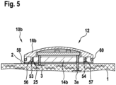
- the component 10b according to the Fig. 5 also has a locking connection 25 between the base part 14b and the closure part 16b, but for this purpose the closure part 16b has insertion pins 53, 54 which protrude into corresponding openings 56, 57 of the base part 14b in order to form the locking connection 25. Furthermore, a radially encircling seal 60, e.g. in the form of an adhesive bead or a sealing ring, is arranged on the radially outer region between the base part 14b and the closure part 16b.
Landscapes
- Engineering & Computer Science (AREA)
- Textile Engineering (AREA)
- General Engineering & Computer Science (AREA)
- Push-Button Switches (AREA)
- Connector Housings Or Holding Contact Members (AREA)
- Coupling Device And Connection With Printed Circuit (AREA)
- Multi-Conductor Connections (AREA)
- Chemical Or Physical Treatment Of Fibers (AREA)
Description
- Die Erfindung betrifft ein Bauelement zur elektrischen Kontaktierung wenigstens eines Funktionselements an einem Textil o.ä. Ferner betrifft die Erfindung eine Anordnung, die ein erfindungsgemäß ausgebildetes Bauelement und ein elektrisch leitende Bereiche aufweisendes Textil o.ä. umfasst.
- Ein Bauelement zur elektrischen Kontaktierung wenigstens eines Funktionselements an einem Textil ist aus der
DE 10 2006 008 796 B3 bekannt. Das bekannte Bauelement ist in Form eines Druckknopfes ausgebildet, wobei der Druckknopf gleichzeitig als Träger bzw. zur Aufnahme eines elektronischen Bauteils o.ä. dient, das Bestandteil des Funktionselements ist. Das elektronische Bauteil weist (elektrische) Anschlusselemente in Form von Drähten auf, die aus der Unterseite des Bauelements herausragen, und die auf nicht näher beschriebene Art und Weise beispielsweise mit einem in Form eines elektrisch leitfähigen Garns ausgebildeten Teils des Textils verbunden sind. - Das Dokument
DE 10 2016 224565 A1 offenbart ein Bauelement gemäß dem Oberbegriff des Anspruchs 1. - Das erfindungsgemäße Bauelement zur elektrischen Kontaktierung wenigstens eines Funktionselements an einem Textil o.ä. mit den Merkmalen des Anspruchs 1 hat den Vorteil, dass es eine besonders einfache und trotzdem zuverlässige elektrische Kontaktierung mit den elektrisch leitenden Bereichen des Textil o.ä. ermöglicht. Der Erfindung liegt die Idee zugrunde, die (elektrischen)
- Anschlusselemente am Bauelement derart auszubilden, dass diese beim Verbinden des Bauelements mit dem Textil o.ä. gleichzeitig eine zuverlässige elektrische Kontaktierung mit den elektrisch leitenden Bereichen des Textils o.ä. ausbilden. Es sind insbesondere keine anschließenden zusätzlichen Arbeitsschritte außer dem Verbinden des Bauelements mit dem Textil o.ä. erforderlich, um die elektrische Verbindung an dem Textil o.ä. auszubilden. Insbesondere sind keine Löt-, Schweiß- oder ähnliche zusätzliche Arbeitsschritte erforderlich, um die elektrischen Anschlusselemente des Bauelements mit den elektrisch leitenden Bereichen des Textils o.ä. zu verbinden.
- Vor diesem Hintergrund schlägt es die Lehre der Erfindung daher vor, dass die Anschlusselemente des Bauelements dazu ausgebildet sind, beim Verbinden des Grundkörpers des Bauelements mit dem Textil o.ä. eine elektrische Verbindung mit den elektrisch leitfähigen Bereichen des Textils o.ä. durch eine kraft- und/oder formschlüssige Verbindung auszubilden. Typischerweise sind die Anschlusselemente am Bauelement derart ausgebildet, dass beim Befestigen des Bauelements an dem Textil o.ä. die Anschlusselemente gegen die elektrisch leitenden Bereiche des Textils o.ä. gedrückt bzw. kraftbeaufschlagt werden und dadurch die elektrische Verbindung ausbilden. Insbesondere zum Toleranzausgleich hinsichtlich der Anordnung der elektrisch leitenden Bereiche im bzw. am Textil o.ä. ist es dabei von Vorteil, wenn die elektrischen Anschlusselemente des Bauelements unter elastischer Vorspannung in Richtung der elektrisch leitenden Bereiche des Textils o.ä. kraftbeaufschlagt sind. Vorteilhafte Weiterbildungen des erfindungsgemäßen Bauelements zur elektrischen Kontaktierung wenigstens eines Funktionselements an einem Textil o.ä. sind in den Unteransprüchen aufgeführt.
- Das Grundkörper des Bauelements gemäß der Erfindung weist Durchgangsöffnungen zur Führung bzw. Aufnahme der Anschlusselemente auf, wobei die Anschlusselemente an einer Unterseite des Grundkörpers des Bauelements aus den Durchgangsöffnungen ggf. herausragen. Dadurch ist es möglich, die Unterseite des Grundkörpers in Anlage mit dem Textil o.ä. anzuordnen, wobei die elektrischen Anschlusselemente bis in Höhe der elektrisch leitenden Bereiche des Textils o.ä. gelangen bzw. dort kraftschlüssig anliegen.
- Gemäß der Erfindung ist es vorgesehen, dass die Anschlusselemente zumindest ein Element aufweisen, das dazu ausgebildet ist, eine elastische Vorspannkraft in Richtung der elektrisch leitfähigen Bereiche des Textils o.ä. zu erzeugen. Beispielsweise sind die elektrischen Anschlusselemente in Form von stiftförmigen Metallteilen ausgebildet, die mit Federelementen zusammenwirken, die die benötigte Vorspannkraft in Richtung der elektrisch leitenden Bereiche des Textils o.ä. ausbilden. Auch ist es denkbar, dass das Federelement als einziges Element das elektrische Anschlusselement ausbildet. Dadurch, dass die Anschlusselemente in den Durchgangsöffnungen des Grundkörpers angeordnet sind, ist darüber hinaus eine Beweglichkeit der Anschlusselemente in deren Längsrichtung innerhalb der Durchgangsöffnungen möglich. Hierzu ist zwischen den Anschlusselementen und den Durchgangsöffnungen vorzugsweise ein (lediglich) geringes Radialspiel bzw. ein geringer Radialspalt ausgebildet.
- Um das Bauelement auf einfache Art und Weise möglichst unterschiedlichsten Anforderungen bzw. Funktionalitäten anpassen zu können und eine Art Baukastensystem zu ermöglichen, sieht es eine weitere bevorzugte Ausgestaltung des Bauelements vor, dass der Grundkörper ein vorzugsweise plattenförmiges, insbesondere einen runden Querschnitt aufweisendes, aus elektrisch nichtleitendem Material bestehendes Basisteil aufweist, dessen Oberseite von einem kappenförmigen Verschlussteil überdeckt, wobei das Verschlussteil vorzugsweise über eine Rastverbindung mit dem Basisteil verbunden ist.
- In Weiterbildung dieses Vorschlags ist es vorgesehen, dass vorzugsweise in dem Verschlussteil eine Aufnahme zur Anordnung wenigstens eines elektrischen und/oder elektronischen Bauelements und/oder des Funktionselements ausgebildet ist. Das Baukastensystem wird dann dadurch ermöglicht, dass beispielsweise ein und dasselbe Basisteil mit unterschiedlichen Verschlussteilen, die entsprechend ausgebildete Aufnahmen für unterschiedlichste Anwendungen bzw. Bauelemente und/oder Funktionselemente aufweist, verbindbar ist.
- Ein spezieller Anwendungsfall, der die Realisierung eines Leuchtelements als Funktionselement an dem Textil o.ä. ermöglicht, sieht vor, dass das Verschlussteil aus transparentem Kunststoff ausgebildet ist, und dass in dem Grundkörper ein Leuchtelement, vorzugsweise eine LED, angeordnet ist.
- Auch hinsichtlich der Befestigung des Bauelements an der Oberfläche des Textils o.ä. gibt es unterschiedliche Möglichkeiten. In einer ersten, bevorzugten Ausgestaltung ist es vorgesehen, dass der Grundkörper das Oberteil eines Druckknopfes ausbildet, der mit einem Unterteil des Druckknopfes unter Ausbildung einer Rastverbindung verbindbar ist, wobei im verrasteten Zustand zwischen dem Oberteil und dem Unterteil ein Zwischenraum zur Fixierung des die elektrisch leitfähigen Bereiche aufweisenden Textils o.ä. ausgebildet ist. Eine derartige Ausgestaltung ermöglicht es, eine besonders einfache manuelle bzw. automatische Befestigung des Bauelements an dem Textil o.ä. vorzunehmen. Darüber hinaus ist beispielsweise ein besonders einfacher Austausch des Bauelements an dem Textil o.ä. möglich, beispielsweise im Falle eines Defekts.
- Es ist jedoch auch denkbar, auf ein Unterteil bzw. auf die Ausbildung eines Druckknopfes zu verzichten. In diesem Fall ist es vorgesehen, dass der Grundkörper des Bauelements dazu ausgebildet ist, mittels einer stoffschlüssigen Verbindung mit dem die elektrisch leitfähigen Bereiche aufweisenden Textil o.ä. verbunden zu werden. Eine derartige stoffschlüssige Verbindung kann beispielsweise in Form eines Klebstoffes ausgebildet sein, oder aber in Form einer Lotschicht, wenn die elektrisch leitfähigen Bereiche sich direkt an der Oberfläche des Textils o.ä. befinden.
- Weiterhin umfasst die Erfindung eine Anordnung, die ein soweit beschriebenes erfindungsgemäßes Bauelement umfasst sowie ein elektrisch leitfähige Bereiche aufweisendes Textil o.ä., wobei die elektrisch leitfähigen Bereiche durch eine kraft- oder formschlüssige Verbindung mittels der Anschlusselemente des Bauelements kontaktiert sind.
- Weiterhin umfasst die Anordnung auch eine Ausgestaltung, bei der die leitfähigen Bereiche in dem Textil o.ä. in unterschiedlichen Ebenen und mit unterschiedlichem Abstand zum Grundkörper des Bauelements angeordnet sind.
- Um es zu ermöglichen, dass das Bauelement auch dazu geeignet ist, eine relativ komplexe Funktionalität aufzuweisen, die üblicherweise unterschiedliche elektrisch leitfähige Bereiche an dem Textil o.ä. benötigen, sieht es eine weitere Ausgestaltung der Anordnung vor, dass die elektrisch leitfähigen Bereiche des Textils o.ä. mit Kontaktstellen verbunden sind oder als Kontaktstellen ausgebildet sind, die mit den Anschlusselementen des Bauelements zusammenwirken, und dass die Kontaktstellen unterschiedliche Längen aufweisen, sodass die Kontaktstellen auf der dem Bauelement zugewandten Seite in einer gemeinsamen Ebene enden.
- Weiterhin kann es vorgesehen sein, dass elektrisch leitfähige Bereiche an der dem Grundkörper zugewandten Oberfläche des Textils o.ä. angeordnet sind, und dass diese elektrisch leitfähigen Bereiche mittels eines elektrisch leitfähigen Klebstoffs oder einer Lotschicht mit dem Grundkörper des Bauelements verbunden sind.
- Das soweit beschriebene Bauelement wurde bisher insbesondere im Zusammenhang mit einem Textil beschrieben. Unter einem Textil wird beispielsweise eine Funktionskleidung oder eine Arbeitsschutzkleidung verstanden, die z.B. Leuchtelemente, Sensorelemente o.ä. als Funktionselemente aufweist. Die Erfindung soll jedoch nicht auf derartige Anwendungen beschränkt sein. Vielmehr kann das Bauelement bei Kleidungsstücken jeglicher Art verwendet werden. Auch kann es vorgesehen, dass das Bauelement Bestandteil für an sich bekannte Flachbaugruppen, z.B. Intermodulverbindungen o.ä. ist. Auch sind Anwendungen im Bereich von Karosserien, beispielsweise von Innenraumkomponenten von Kfz denkbar. Weitere Anwendungen bestehen beispielsweise bei Gebäuden im Bereich von Brandmeldern, Smart Home-Sensoren o.ä. Weiterhin sind auch Anwendungen im Bereich von Sportgeräten, wie Fahrrädern, E-Bikes, Ski o.ä. denkbar, ebenso wie im Bereich von Messgeräten.
- Weitere Vorteile, Merkmale und Einzelheiten der Erfindung ergeben sich aus der nachfolgenden Beschreibung bevorzugter Ausführungsbeispiele sowie anhand der Zeichnungen.
-
- Fig. 1
- zeigt in einem vereinfachten Schnitt eine erste Ausführungsform eines mit einem Textil verbundenen Bauelements als Bestandteil eines Druckknopfes,
- Fig. 2a bis Fig. 2c
- unterschiedliche elektrische Kontaktierungen zwischen einem Anschlusselement und einem elektrisch leitenden Bereich des Textils,
- Fig. 3
- eine vereinfachte Darstellung eines mit einem Leuchtelement versehenen kappenförmigen Verschlussteils, und
- Fig. 4 und Fig. 5
- jeweils in Schnittdarstellungen, gegenüber der
Fig. 1 abgewandelte Bauelemente, die unmittelbar mit einem Textil verbunden sind. - Gleiche Elemente bzw. Elemente mit gleicher Funktion sind in den Figuren mit den gleichen Bezugsziffern versehen.
- In der
Fig. 1 ist ein erstes Bauelement 10 zur elektrischen Kontaktierung wenigstens eines Funktionselements an einem Textil 1 dargestellt. Bei dem Textil 1 kann es sich z.B. um ein Kleidungsstück, wie eine Jacke, eine Arbeitsschutzkleidung o.ä. handeln. Die Erfindung soll jedoch nicht auf tragbare Textilen 1 beschränkt sein. Vielmehr kann anstatt des Textils 1 auch ein sonstiger Funktionsträger aus einem flexiblen Material, wie eine Flexleiterplatte vorgesehen sein. Auch sind andere Anwendungen der Erfindung, beispielsweise für sogenannte Flachbaugruppen, z.B. Intermodulverbindungen, Innenraumkomponenten von Kfz, Teile von Gebäuden wie z.B. Brandmelder, Smart Home-Sensoren, Sportgeräte wie z.B. Fahrräder, Ski, Messgeräte o.ä. Anwendungen für die Erfindung denkbar. - Das Bauelement 10 weist einen Grundkörper 12 auf, der aus einem Basisteil 14 und einem mit dem Basisteil 14 verbundenen, kappenförmigen Verschlussteil 16 besteht. Das Basisteil 14 ist plattenförmig ausgebildet und weist beispielhaft einen runden Querschnitt auf. Das Basisteil 14 besteht aus einem elektrisch nichtleitenden Kunststoff, wobei die dem Textil 1 abgewandte Oberseite des Basisteils 14 von dem Verschlussteil 16 überdeckt ist. Das Verschlussteil 16 besteht ebenfalls aus Kunststoff und weist eine Aufnahme 18 auf, in der beispielhaft eine Leiterplatte 20 bzw. ein Substrat als Funktionselement angeordnet ist, auf dem elektronische Bauteile 22 angeordnet sind. Die Leiterplatte 20 ist beispielhaft innerhalb der Aufnahme 18 zumindest bereichsweise von einer Moldmasse 24 umgeben. Das Verschlussteil 16 ist über eine Rastverbindung 25 mit dem Basisteil 14 verbunden. Die Rastverbindung 25 umfasst eine radial an dem Verschlussteil 16 umlaufende Rastnase 26, die in eine gegengleiche Rastöffnung 27 am Basisteil 14 eingreift.
- Wesentlich ist, dass das Verschlussteil 16 zusammen mit der Leiterplatte 20 bzw. den Bauelementen 22 zusammen mit dem Basisteil 14 ein Baukastensystem darstellt, d.h., dass auch andere Verschlussteile 16 für andere Anwendungen mit ein und demselben Basisteil 14 verwendet werden können.
- In dem Basisteil 14 sind darüber hinaus beispielhaft zwei Durchgangsöffnungen 28, 29 ausgebildet, die von Anschlusselementen 30, 31 durchsetzt sind. Die Anschlusselemente 30, 31 dienen der elektrischen Kontaktierung der Leiterplatte 20 mit an dem Textil 1 ausgebildeten, elektrisch leitfähigen Bereichen 2 durch eine kraft- und/oder formschlüssige Verbindung. Bei den elektrisch leitfähigen Bereichen 2 an dem Textil 1 handelt es sich allgemein gesprochen um elektrische Leiterbahnen, die z.B. in Form eines elektrisch leitfähigen Garns ausgebildet sein können, und die durch gängige Verbindungstechniken mit dem Grundmaterial des Textils 1 verbunden sind, d.h., z.B. durch Sticken, Weben, Drucken oder auf sonstige geeignete Art und Weise.
- In dem in der
Fig. 1 dargestellten Ausführungsbeispiel sind die elektrisch leitfähigen Bereiche 2 auf der dem Grundkörper 12 zugewandten Oberseite des Textils 1 angeordnet. Im Bereich der Durchgangsöffnungen 28, 29 weisen die elektrisch leitfähigen Bereiche 2 Kontaktstellen 3, 4, z.B. in Form von Pads auf, die mit den Anschlusselementen 30, 31 kraft- und/oder formschlüssig kontaktiert sind. - Die elektrischen Anschlusselemente 30, 31 können ebenfalls in vielfältiger Art und Weise ausgebildet sein, z.B. in Form von Stiften, Federn, Schneidklemmen o.ä. Wesentlich ist lediglich, dass die Anschlusselemente 30, 31 eine elektrische Kontaktierung zwischen dem Bauelement 10 bzw. der Leiterplatte 20 und den elektrisch leitfähigen Bereichen 2 an dem Textil 1 sicherstellen.
- Entsprechend der
Fig. 2a ist es beispielsweise vorgesehen, dass das Anschlusselement 30 einen Stift 32 aufweist, der mit einer Druckfeder 33 verbunden ist. Die Druckfeder 33 ist wiederum über ein Element 34 fest mit der Leiterplatte 20 verbunden, beispielswiese durch eine Lötverbindung, eine Einpressverbindung. Der Stift 32 ist durch die Druckfeder 33 in Richtung der Kontaktstelle 3 kraftbeaufschlagt und liegt dort unter Federvorspannung an. Bei dem in derFig. 2a dargestellten Beispiel ist der elektrisch leitfähige Bereich 2 innerhalb des Textils 1, d.h. in einem Abstand zum Basisteil 14 angeordnet. - Bei einer nicht gezeigten Modifikation des Beispiels der
Fig. 2a kann es vorgesehen sein, dass der Stift 32 fest mit der Kontaktstelle 3 verbunden ist oder zusammen mit der Kontaktstelle 3 monolithisch ausgebildet ist und in die Durchgangsöffnung 28 hineinragt. Dort liegt die dem Stift 32 zugewandte Stirnseite der Druckfeder 33 unter Federvorspannung an dem Stift 32 an. - In der
Fig. 2b ist dargestellt, dass das Anschlusselement 30 eine in der Durchgangsbohrung 28 unter Ausbildung einer Presspassung angeordnete Platte 35 aufweist, an deren gegenüberliegenden Stirnflächen zwei Druckfedern 36, 37 angeordnet sind, die unter Federvorspannung an der Leiterplatte 20 bzw. der Kontaktstelle 3 anliegen. - In der
Fig. 2c ist dargestellt, dass das stiftförmige Anschlusselement 30 unmittelbar mit dem Bereich 2 bzw. der Kontaktstelle 3 fest verbunden ist. Das Anschlusselement durchdringt die Durchgangsöffnung 28 und liegt unter axialer Vorspannung an der Leiterplatte 20 an. Die Vorspannung wird durch eine entsprechende Länge des Anschlusselements 30 sichergestellt, die größer ist als die Dicke des Basisteils 14 im Bereich der Durchgangsöffnung 28, sodass das Anschlusselement 30 bei Anlage an der Leiterplatte 20 etwas in Richtung des Textils 1 gedrückt wird. - Auch hinsichtlich der Verbindung des Bauelements 10 mit dem Textil 1 gibt es unterschiedliche Möglichkeiten. In der
Fig. 1 ist beispielhaft dargestellt, dass das Bauelement 10 Teil eines Druckknopfes 40 ist, wobei das Bauelement 10 das Oberteil 41 des Druckknopfes 40 ausbildet. Hierzu ist an dem Basisteil 14 auf der dem Verschlussteil 16 abgewandten Seite ein zapfenförmiger Fortsatz 42 ausgebildet bzw. angeformt, der mit einem plattenförmigen, ein Unterteil 43 des Druckknopfes 40 ausbildenden Element zusammenwirkt. Das Unterteil 43 ist beispielhaft ebenfalls plattenförmig ausgebildet und weist denselben Querschnitt auf wie das Basisteil 14. Weiterhin hat es eine zentrale Öffnung 44, die dazu ausgebildet ist, mit dem Fortsatz 42 eine Rastverbindung 45 auszubilden. - Die Montage des Bauelements 10 und somit die elektrische Kontaktierung der Leiterplatte 20 an dem Textil 1 erfolgt dadurch, dass das Unterteil 43 mit dem Oberteil 41des Druckknopfes 40 unter Zwischenlage des Textils 1 verbunden wird. Dabei gelangen die Anschlusselemente 30, 31 zwangsweise in Kontakt mit den elektrisch leitfähigen Bereichen 2 des Textils 1.
- Ergänzend wird erwähnt, dass hinsichtlich der genauen Positionierung bzw. Ausrichtung des Grundkörpers 12 zum Textil 1 mit Blick auf den Ort der Kontaktierung der elektrisch leitfähigen Bereiche 2 entsprechende Elemente bzw. Maßnahmen vorgesehen sein müssen.
- In der
Fig. 3 ist stark vereinfacht dargestellt, dass auf der Oberseite einer Leiterplatte 20a ein Leuchtelement 48 in Form einer LED angeordnet ist. Weiterhin besteht das Material des (kappenförmigen) Verschlussteils 16a aus einem transparenten Kunststoff, sodass bei einer Aktivierung des Leuchtmittels 48 das Bauelement 10 bzw. das Verschlussteil 16a eine Durchlässigkeit des Lichtes des Leuchtelements 48 ermöglicht. - Bei den Ausführungsformen gemäß der
Fig. 4 und5 mit den Bauelementen 10a und 10b ist gemeinsam, dass diese nicht in Form eines Druckknopfes 40 ausgebildet sind, sondern dass der Grundkörper 12 unmittelbar mit dem Textil 1 an dessen dem Grundkörper 12 zugewandten Oberseite durch eine stoffschlüssige Verbindung 50 verbunden ist. Bei der stoffschlüssigen Verbindung 50 kann es sich beispielhaft um eine Klebeverbindung oder aber um eine Lötverbindung handeln. Weiterhin ist den beiden Bauelementen 10a, 10b bzw. dem Textil 1 gemeinsam, dass innerhalb des Textils 1 elektrisch leitende Bereiche 5, 6 vorgesehen sind, die auf unterschiedlichem Höhenniveau bzw. in unterschiedlichen Ebenen innerhalb des Textils 1 angeordnet sind. - Das Bauelement 10a gemäß der
Fig. 4 entspricht im Wesentlichen dem Bauelement 10 gemäß derFig. 1 . Im Unterschied dazu erkennt man jedoch, dass der die beiden elektrisch leitfähigen Bereich 5, 6 an dem Textil 1 jeweils einen Kontaktbereich 3a aufweisen, der die Distanz zwischen dem elektrisch leitfähigen Bereich 5, 6 zur Ebene der Oberseite des Textils 1 bzw. zur Ebene des Basisteils 14 überbrückt. Weiterhin erkennt man, dass zwischen dem Basisteil 14 und dem Verschlussteil 16 ein Verdrehschutz 52 angeordnet ist, z.B. in Form eines Stiftes. - Das Bauelement 10b gemäß der
Fig. 5 weist ebenfalls eine Rastverbindung 25 zwischen dem Basisteil 14b und dem Verschlussteil 16b auf, jedoch weist hierzu das Verschlussteil 16b Einsteckpins 53, 54 auf, die in entsprechende Öffnungen 56, 57 des Basisteils 14b hineinragen, um die Rastverbindung 25 auszubilden. Ferner ist am radial äußeren Bereich zwischen dem Basisteil 14b und dem Verschlussteil 16b eine radial umlaufende Dichtung 60, z.B. in Form einer Kleberaupe oder eines Dichtrings angeordnet.
Claims (10)
- Bauelement (10; 10a; 10b) zur elektrischen Kontaktierung wenigstens eines Funktionselements (20; 20a) an einem Textil (1) o.ä., mit einem zumindest ein elektrisches Bauelement (22, 48) und/oder ein Funktionselement (20; 20a) aufnehmenden Grundkörper (12), und mit Anschlusselementen (30, 31) zur elektrischen Kontaktierung von elektrisch leitfähigen Bereichen (2, 5, 6) des Textils (1) o.ä., wobei die Anschlusselemente (30, 31) dazu ausgebildet sind, beim Verbinden des Grundkörpers (12) mit dem Textil (1) o.ä. eine elektrische Verbindung mit den elektrisch leitfähigen Bereichen (2, 5, 6) des Textils (1) o.ä. durch eine kraft- und/oder formschlüssige Verbindung auszubilden, und wobei der Grundkörper (12) Durchgangsöffnungen (28, 29) zur Führung der Anschlusselemente (30, 31) aufweist, wobei die Anschlusselemente (30, 31) an einer Unterseite des Grundkörpers (12) aus den Durchgangsöffnungen (28, 29) ggf. herausragen,
dadurch gekennzeichnet,
dass die Anschlusselemente (30) zumindest ein Element (33; 36, 37) aufweisen, das dazu ausgebildet ist, eine elastische Vorspannkraft in Richtung der elektrisch leitfähigen Bereiche (2, 5, 6) des Textils (1) o.ä. zu erzeugen. - Bauelement nach Anspruch 1,
dadurch gekennzeichnet,
dass der Grundkörper (12) ein vorzugsweise plattenförmiges, einen runden Querschnitt aufweisendes aus elektrisch nicht leitendem Material bestehendes Basisteil (14; 14b) aufweist, dessen Oberseite von einem kappenförmigen Verschlussteil (16; 16a; 16b) überdeckt ist, wobei das Verschlussteil (16; 16a; 16b) vorzugsweise über eine Rastverbindung (25) mit dem Basisteil (14; 14b) verbunden ist. - Bauelement nach Anspruch 2,
dadurch gekennzeichnet,
dass vorzugsweise in dem Verschlussteil (16; 16a; 16b) eine Aufnahme (18) zur Anordnung des elektrischen Bauelements (22, 48) und/oder des Funktionselements (20; 20a) ausgebildet ist. - Bauelement nach Anspruch 2 oder 3,
dadurch gekennzeichnet,
dass das Verschlussteil (16a) aus transparentem Kunststoff ausgebildet ist, und dass in dem Grundkörper (12) ein Leuchtelement (48), vorzugsweise eine LED angeordnet ist. - Bauelement nach einem der Ansprüche 1 bis 4,
dadurch gekennzeichnet,
dass der Grundkörper (12) als Oberteil (41) eines Druckknopfes (40) ausgebildet ist, der mit einem Unterteil (43) des Druckknopfes (40) unter Ausbildung einer Rastverbindung (45) verbindbar ist, wobei im verbundenen Zustand zwischen dem Oberteil (41) und dem Unterteil (43) ein Zwischenraum zur Fixierung des die elektrisch leitfähigen Bereiche (2, 5, 6) aufweisenden Textils (1) o.ä. ausgebildet ist. - Bauelement nach einem der Ansprüche 1 bis 4,
dadurch gekennzeichnet,
dass der Grundkörper (12) dazu ausgebildet ist, mittels einer stoffschlüssigen Verbindung (50) mit dem die elektrisch leitfähigen Bereiche (2, 5, 6) aufweisenden Textil (1) o.ä. verbunden zu werden. - Anordnung, aufweisend ein Bauelement (10; 10a; 10b), das nach einem der Ansprüche 1 bis 6 ausgebildet ist, und ein elektrisch leitfähige Bereiche (2, 5, 6) aufweisendes Textil (1) o.ä., wobei die elektrisch leitfähigen Bereiche (2, 5, 6) mit dem Bauelement (10; 10a; 10b) durch eine kraft- oder formschlüssige Verbindung mittels der Anschlusselemente (30) kontaktiert sind.
- Anordnung nach Anspruch 7,
dadurch gekennzeichnet,
dass die leitfähigen Bereiche (5, 6) an dem Textil (1) o.ä. in unterschiedlichen Ebenen und mit unterschiedlichem Abstand zum Grundkörper (12) des Bauelements (10a; 10b) angeordnet sind. - Anordnung nach Anspruch 8,
dadurch gekennzeichnet,
dass die elektrisch leitfähigen Bereiche (2, 5, 6) des Textils (1) o.ä. mit Kontaktstellen (3; 3a, 4) verbunden sind oder als Kontaktstellen (3; 3a, 4) ausgebildet sind, die mit den Anschlusselementen (30, 31) des Bauelements (10; 10a; 10b) zusammenwirken, und dass die Kontaktstellen (3a, 3b) unterschiedliche Längen aufweisen, sodass die Kontaktstellen (3a; 3b) auf der dem Bauelement (10; 10a; 10b) zugewandten Seite in einer gemeinsamen Ebene enden. - Anordnung nach einem der Ansprüche 7 bis 9,
dadurch gekennzeichnet,
dass, dass elektrisch leitfähige Bereiche (2) an der dem Grundkörper (12) zugewandten Oberfläche des Textils (1) o.ä. angeordnet sind, und dass die elektrisch leitfähigen Bereiche (2) mittels eines elektrisch leitfähigen Klebstoffs oder einer Lotschicht als stoffschlüssige Verbindung (50) mit dem Grundkörper (12) des Bauelements (10; 10b) verbunden sind.
Applications Claiming Priority (2)
| Application Number | Priority Date | Filing Date | Title |
|---|---|---|---|
| DE102019217290.3A DE102019217290A1 (de) | 2019-11-08 | 2019-11-08 | Bauelement zur elektrischen Kontaktierung wenigstens eines Funktionselements an einem Textil o.ä. und Anordnung mit einem Bauelement |
| PCT/EP2020/076546 WO2021089227A1 (de) | 2019-11-08 | 2020-09-23 | Bauelement zur elektrischen kontaktierung wenigstens eines funktionselements an einem textil o.ä. und anordnung mit einem bauelement |
Publications (2)
| Publication Number | Publication Date |
|---|---|
| EP4054377A1 EP4054377A1 (de) | 2022-09-14 |
| EP4054377B1 true EP4054377B1 (de) | 2024-11-06 |
Family
ID=72644234
Family Applications (1)
| Application Number | Title | Priority Date | Filing Date |
|---|---|---|---|
| EP20780157.2A Active EP4054377B1 (de) | 2019-11-08 | 2020-09-23 | Bauelement zur elektrischen kontaktierung wenigstens eines funktionselements an einem textil o.ä. und anordnung mit einem bauelement |
Country Status (5)
| Country | Link |
|---|---|
| US (1) | US11825897B2 (de) |
| EP (1) | EP4054377B1 (de) |
| CN (1) | CN114599249B (de) |
| DE (1) | DE102019217290A1 (de) |
| WO (1) | WO2021089227A1 (de) |
Families Citing this family (3)
| Publication number | Priority date | Publication date | Assignee | Title |
|---|---|---|---|---|
| US12560310B2 (en) * | 2023-09-05 | 2026-02-24 | Kuzco Lighting Llc | Strap lighting |
| US12529471B2 (en) * | 2023-09-05 | 2026-01-20 | Kuzco Lighting Llc | Strap lighting |
| DE102024002908A1 (de) * | 2024-09-10 | 2026-03-12 | Noxon GmbH | Elektronische Schaltung auf einem textilen Träger und Herstellverfahren |
Family Cites Families (8)
| Publication number | Priority date | Publication date | Assignee | Title |
|---|---|---|---|---|
| US5440461A (en) * | 1994-05-02 | 1995-08-08 | Nadel; Craig P. | Light illuminating assemblies for wearing apparel with light element securement means |
| DE102006008796B3 (de) | 2006-02-24 | 2007-12-27 | Interactive Wear Ag | Fixiervorrichtung mit integrierter Elektronikkomponente |
| GB2487755A (en) * | 2011-02-03 | 2012-08-08 | Steven Leftly | Removable and wearable light modules |
| DE202013105122U1 (de) | 2013-11-13 | 2014-01-13 | King's Metal Fiber Technologies Co., Ltd. | Leuchtender Kleidungsknopfmodul |
| US20150170480A1 (en) * | 2013-12-12 | 2015-06-18 | King's Metal Fiber Technologies Co., Ltd. | Structure of light emitting clip button |
| US20150164183A1 (en) * | 2013-12-12 | 2015-06-18 | King's Metal Fiber Technologies Co., Ltd. | Light-emitting button module |
| US9445641B1 (en) | 2014-05-12 | 2016-09-20 | Carmen Rapisarda | LED lighting module |
| DE102016224565A1 (de) | 2016-12-09 | 2018-06-14 | Robert Bosch Gmbh | Textil- und/oder Bekleidungseinheit |
-
2019
- 2019-11-08 DE DE102019217290.3A patent/DE102019217290A1/de not_active Withdrawn
-
2020
- 2020-09-23 WO PCT/EP2020/076546 patent/WO2021089227A1/de not_active Ceased
- 2020-09-23 EP EP20780157.2A patent/EP4054377B1/de active Active
- 2020-09-23 US US17/772,733 patent/US11825897B2/en active Active
- 2020-09-23 CN CN202080077316.4A patent/CN114599249B/zh active Active
Also Published As
| Publication number | Publication date |
|---|---|
| US20220338572A1 (en) | 2022-10-27 |
| WO2021089227A1 (de) | 2021-05-14 |
| DE102019217290A1 (de) | 2021-05-12 |
| US11825897B2 (en) | 2023-11-28 |
| CN114599249B (zh) | 2024-08-06 |
| EP4054377A1 (de) | 2022-09-14 |
| CN114599249A (zh) | 2022-06-07 |
Similar Documents
| Publication | Publication Date | Title |
|---|---|---|
| EP0712265B1 (de) | Baugruppe | |
| EP1890162B1 (de) | Elektrische Mess-Vorrichtung | |
| EP0904613B1 (de) | Steckverbinder mit einer mit elektrischen bauelementen bestückten leiterbahnstruktur sowie verfahren zur herstellung eines solchen | |
| DE10017335A1 (de) | Elektronische Baugruppe | |
| EP2880717B1 (de) | Einpresspin | |
| EP4054377A1 (de) | Bauelement zur elektrischen kontaktierung wenigstens eines funktionselements an einem textil o.ä. und anordnung mit einem bauelement | |
| WO2009030553A1 (de) | Elektrische schaltanordnung mit einem mid-schaltungsträger und einer damit verbundenen verbindungsschnittstelle | |
| DE102005009443A1 (de) | Folienantenne für ein Fahrzeug | |
| EP2085785B1 (de) | Vorrichtung zur Strommessung | |
| DE102008035420A1 (de) | Modulare Schaltungsanordnung | |
| DE102011085471B4 (de) | Anordnung zur Direktkontaktierung von Kontaktmitteln und zugehörige Anschlusseinheit für eine Druckmesszelle | |
| DE29713988U1 (de) | Verbinder zum Verbinden einer Leiterplatte mit einem flexiblen Folienleiter | |
| WO2020043341A1 (de) | Elektronikmodul und verfahren zum fertigen desselben | |
| EP0980322A2 (de) | Sensorschaltung, insbesondere für kraftfahrzeuge | |
| EP3643147B1 (de) | Elektronikmodul | |
| DE102020208805A1 (de) | Kameramodul, Verfahren zur Herstellung eines Kameramoduls | |
| WO2018108757A1 (de) | Verfahren zum verbinden eines bauelementträgers mit einer leiterplatte und verbund aus einer leiterplatte und einem bauelementträger | |
| WO2012079842A1 (de) | Adaptiervorrichtung und verfahren zur herstellung einer steuergerätbaugruppe | |
| EP1238444B1 (de) | Unlösbare elektrische und mechanische verbindung, kontaktteil für eine unlösbare elektrische und mechanische verbindung und verfahren zur herstellung einer unlösbaren elektrischen und mechanischen verbindung | |
| DE102005053973A1 (de) | Sensorbaugruppe | |
| EP1162694B1 (de) | Vorrichtung zum Verbinden von elektrischen Leitern | |
| DE10345632B4 (de) | Anordnung mit einem Sensor | |
| DE102008014822A1 (de) | Leiterplattenanordnung | |
| WO2015132062A1 (de) | Verbindungsanordnung, verfahren zum herstellen einer verbindungsanordnung und elektrisches gerät mit einer verbindungsanordnung | |
| WO2013010836A2 (de) | Steckermodul, insbesondere für fensterheberantriebe, sowie verfahren zu dessen herstellung |
Legal Events
| Date | Code | Title | Description |
|---|---|---|---|
| STAA | Information on the status of an ep patent application or granted ep patent |
Free format text: STATUS: UNKNOWN |
|
| STAA | Information on the status of an ep patent application or granted ep patent |
Free format text: STATUS: THE INTERNATIONAL PUBLICATION HAS BEEN MADE |
|
| PUAI | Public reference made under article 153(3) epc to a published international application that has entered the european phase |
Free format text: ORIGINAL CODE: 0009012 |
|
| STAA | Information on the status of an ep patent application or granted ep patent |
Free format text: STATUS: REQUEST FOR EXAMINATION WAS MADE |
|
| 17P | Request for examination filed |
Effective date: 20220608 |
|
| AK | Designated contracting states |
Kind code of ref document: A1 Designated state(s): AL AT BE BG CH CY CZ DE DK EE ES FI FR GB GR HR HU IE IS IT LI LT LU LV MC MK MT NL NO PL PT RO RS SE SI SK SM TR |
|
| DAV | Request for validation of the european patent (deleted) | ||
| DAX | Request for extension of the european patent (deleted) | ||
| STAA | Information on the status of an ep patent application or granted ep patent |
Free format text: STATUS: EXAMINATION IS IN PROGRESS |
|
| 17Q | First examination report despatched |
Effective date: 20240305 |
|
| GRAP | Despatch of communication of intention to grant a patent |
Free format text: ORIGINAL CODE: EPIDOSNIGR1 |
|
| STAA | Information on the status of an ep patent application or granted ep patent |
Free format text: STATUS: GRANT OF PATENT IS INTENDED |
|
| INTG | Intention to grant announced |
Effective date: 20240726 |
|
| GRAS | Grant fee paid |
Free format text: ORIGINAL CODE: EPIDOSNIGR3 |
|
| GRAA | (expected) grant |
Free format text: ORIGINAL CODE: 0009210 |
|
| STAA | Information on the status of an ep patent application or granted ep patent |
Free format text: STATUS: THE PATENT HAS BEEN GRANTED |
|
| AK | Designated contracting states |
Kind code of ref document: B1 Designated state(s): AL AT BE BG CH CY CZ DE DK EE ES FI FR GB GR HR HU IE IS IT LI LT LU LV MC MK MT NL NO PL PT RO RS SE SI SK SM TR |
|
| REG | Reference to a national code |
Ref country code: GB Ref legal event code: FG4D Free format text: NOT ENGLISH |
|
| REG | Reference to a national code |
Ref country code: CH Ref legal event code: EP |
|
| REG | Reference to a national code |
Ref country code: DE Ref legal event code: R096 Ref document number: 502020009713 Country of ref document: DE |
|
| REG | Reference to a national code |
Ref country code: IE Ref legal event code: FG4D Free format text: LANGUAGE OF EP DOCUMENT: GERMAN |
|
| REG | Reference to a national code |
Ref country code: LT Ref legal event code: MG9D |
|
| REG | Reference to a national code |
Ref country code: NL Ref legal event code: MP Effective date: 20241106 |
|
| PG25 | Lapsed in a contracting state [announced via postgrant information from national office to epo] |
Ref country code: HR Free format text: LAPSE BECAUSE OF FAILURE TO SUBMIT A TRANSLATION OF THE DESCRIPTION OR TO PAY THE FEE WITHIN THE PRESCRIBED TIME-LIMIT Effective date: 20241106 Ref country code: PT Free format text: LAPSE BECAUSE OF FAILURE TO SUBMIT A TRANSLATION OF THE DESCRIPTION OR TO PAY THE FEE WITHIN THE PRESCRIBED TIME-LIMIT Effective date: 20250306 Ref country code: IS Free format text: LAPSE BECAUSE OF FAILURE TO SUBMIT A TRANSLATION OF THE DESCRIPTION OR TO PAY THE FEE WITHIN THE PRESCRIBED TIME-LIMIT Effective date: 20250306 |
|
| PG25 | Lapsed in a contracting state [announced via postgrant information from national office to epo] |
Ref country code: NL Free format text: LAPSE BECAUSE OF FAILURE TO SUBMIT A TRANSLATION OF THE DESCRIPTION OR TO PAY THE FEE WITHIN THE PRESCRIBED TIME-LIMIT Effective date: 20241106 Ref country code: FI Free format text: LAPSE BECAUSE OF FAILURE TO SUBMIT A TRANSLATION OF THE DESCRIPTION OR TO PAY THE FEE WITHIN THE PRESCRIBED TIME-LIMIT Effective date: 20241106 |
|
| PG25 | Lapsed in a contracting state [announced via postgrant information from national office to epo] |
Ref country code: BG Free format text: LAPSE BECAUSE OF FAILURE TO SUBMIT A TRANSLATION OF THE DESCRIPTION OR TO PAY THE FEE WITHIN THE PRESCRIBED TIME-LIMIT Effective date: 20241106 |
|
| PG25 | Lapsed in a contracting state [announced via postgrant information from national office to epo] |
Ref country code: ES Free format text: LAPSE BECAUSE OF FAILURE TO SUBMIT A TRANSLATION OF THE DESCRIPTION OR TO PAY THE FEE WITHIN THE PRESCRIBED TIME-LIMIT Effective date: 20241106 |
|
| PG25 | Lapsed in a contracting state [announced via postgrant information from national office to epo] |
Ref country code: NO Free format text: LAPSE BECAUSE OF FAILURE TO SUBMIT A TRANSLATION OF THE DESCRIPTION OR TO PAY THE FEE WITHIN THE PRESCRIBED TIME-LIMIT Effective date: 20250206 |
|
| PG25 | Lapsed in a contracting state [announced via postgrant information from national office to epo] |
Ref country code: GR Free format text: LAPSE BECAUSE OF FAILURE TO SUBMIT A TRANSLATION OF THE DESCRIPTION OR TO PAY THE FEE WITHIN THE PRESCRIBED TIME-LIMIT Effective date: 20250207 Ref country code: LV Free format text: LAPSE BECAUSE OF FAILURE TO SUBMIT A TRANSLATION OF THE DESCRIPTION OR TO PAY THE FEE WITHIN THE PRESCRIBED TIME-LIMIT Effective date: 20241106 |
|
| PG25 | Lapsed in a contracting state [announced via postgrant information from national office to epo] |
Ref country code: PL Free format text: LAPSE BECAUSE OF FAILURE TO SUBMIT A TRANSLATION OF THE DESCRIPTION OR TO PAY THE FEE WITHIN THE PRESCRIBED TIME-LIMIT Effective date: 20241106 |
|
| PG25 | Lapsed in a contracting state [announced via postgrant information from national office to epo] |
Ref country code: RS Free format text: LAPSE BECAUSE OF FAILURE TO SUBMIT A TRANSLATION OF THE DESCRIPTION OR TO PAY THE FEE WITHIN THE PRESCRIBED TIME-LIMIT Effective date: 20250206 |
|
| PG25 | Lapsed in a contracting state [announced via postgrant information from national office to epo] |
Ref country code: SM Free format text: LAPSE BECAUSE OF FAILURE TO SUBMIT A TRANSLATION OF THE DESCRIPTION OR TO PAY THE FEE WITHIN THE PRESCRIBED TIME-LIMIT Effective date: 20241106 |
|
| PG25 | Lapsed in a contracting state [announced via postgrant information from national office to epo] |
Ref country code: DK Free format text: LAPSE BECAUSE OF FAILURE TO SUBMIT A TRANSLATION OF THE DESCRIPTION OR TO PAY THE FEE WITHIN THE PRESCRIBED TIME-LIMIT Effective date: 20241106 |
|
| PG25 | Lapsed in a contracting state [announced via postgrant information from national office to epo] |
Ref country code: EE Free format text: LAPSE BECAUSE OF FAILURE TO SUBMIT A TRANSLATION OF THE DESCRIPTION OR TO PAY THE FEE WITHIN THE PRESCRIBED TIME-LIMIT Effective date: 20241106 |
|
| PG25 | Lapsed in a contracting state [announced via postgrant information from national office to epo] |
Ref country code: RO Free format text: LAPSE BECAUSE OF FAILURE TO SUBMIT A TRANSLATION OF THE DESCRIPTION OR TO PAY THE FEE WITHIN THE PRESCRIBED TIME-LIMIT Effective date: 20241106 |
|
| PG25 | Lapsed in a contracting state [announced via postgrant information from national office to epo] |
Ref country code: SK Free format text: LAPSE BECAUSE OF FAILURE TO SUBMIT A TRANSLATION OF THE DESCRIPTION OR TO PAY THE FEE WITHIN THE PRESCRIBED TIME-LIMIT Effective date: 20241106 |
|
| PG25 | Lapsed in a contracting state [announced via postgrant information from national office to epo] |
Ref country code: CZ Free format text: LAPSE BECAUSE OF FAILURE TO SUBMIT A TRANSLATION OF THE DESCRIPTION OR TO PAY THE FEE WITHIN THE PRESCRIBED TIME-LIMIT Effective date: 20241106 |
|
| PG25 | Lapsed in a contracting state [announced via postgrant information from national office to epo] |
Ref country code: IT Free format text: LAPSE BECAUSE OF FAILURE TO SUBMIT A TRANSLATION OF THE DESCRIPTION OR TO PAY THE FEE WITHIN THE PRESCRIBED TIME-LIMIT Effective date: 20241106 |
|
| REG | Reference to a national code |
Ref country code: DE Ref legal event code: R097 Ref document number: 502020009713 Country of ref document: DE |
|
| PG25 | Lapsed in a contracting state [announced via postgrant information from national office to epo] |
Ref country code: SE Free format text: LAPSE BECAUSE OF FAILURE TO SUBMIT A TRANSLATION OF THE DESCRIPTION OR TO PAY THE FEE WITHIN THE PRESCRIBED TIME-LIMIT Effective date: 20241106 |
|
| PLBE | No opposition filed within time limit |
Free format text: ORIGINAL CODE: 0009261 |
|
| STAA | Information on the status of an ep patent application or granted ep patent |
Free format text: STATUS: NO OPPOSITION FILED WITHIN TIME LIMIT |
|
| 26N | No opposition filed |
Effective date: 20250807 |
|
| PGFP | Annual fee paid to national office [announced via postgrant information from national office to epo] |
Ref country code: DE Payment date: 20251121 Year of fee payment: 6 |
|
| REG | Reference to a national code |
Ref country code: CH Ref legal event code: H13 Free format text: ST27 STATUS EVENT CODE: U-0-0-H10-H13 (AS PROVIDED BY THE NATIONAL OFFICE) Effective date: 20260504 |