EP4053973A1 - Energy storage module - Google Patents
Energy storage module Download PDFInfo
- Publication number
- EP4053973A1 EP4053973A1 EP22158568.0A EP22158568A EP4053973A1 EP 4053973 A1 EP4053973 A1 EP 4053973A1 EP 22158568 A EP22158568 A EP 22158568A EP 4053973 A1 EP4053973 A1 EP 4053973A1
- Authority
- EP
- European Patent Office
- Prior art keywords
- side wall
- energy storage
- storage module
- housing
- conductive material
- Prior art date
- Legal status (The legal status is an assumption and is not a legal conclusion. Google has not performed a legal analysis and makes no representation as to the accuracy of the status listed.)
- Granted
Links
- 238000004146 energy storage Methods 0.000 title claims abstract description 48
- 239000004020 conductor Substances 0.000 claims abstract description 26
- 210000000352 storage cell Anatomy 0.000 claims abstract description 19
- 239000012530 fluid Substances 0.000 claims description 14
- 239000000463 material Substances 0.000 claims description 7
- 125000006850 spacer group Chemical group 0.000 claims description 6
- 238000000034 method Methods 0.000 claims description 3
- 230000002093 peripheral effect Effects 0.000 claims description 2
- 238000007373 indentation Methods 0.000 claims 1
- 238000000926 separation method Methods 0.000 claims 1
- 238000011161 development Methods 0.000 description 14
- 230000018109 developmental process Effects 0.000 description 14
- 238000001816 cooling Methods 0.000 description 8
- 229910052751 metal Inorganic materials 0.000 description 7
- 239000002184 metal Substances 0.000 description 7
- 210000004027 cell Anatomy 0.000 description 5
- 230000017525 heat dissipation Effects 0.000 description 3
- 238000005452 bending Methods 0.000 description 2
- 239000012777 electrically insulating material Substances 0.000 description 2
- 229910052782 aluminium Inorganic materials 0.000 description 1
- XAGFODPZIPBFFR-UHFFFAOYSA-N aluminium Chemical compound [Al] XAGFODPZIPBFFR-UHFFFAOYSA-N 0.000 description 1
- 230000009286 beneficial effect Effects 0.000 description 1
- 230000000295 complement effect Effects 0.000 description 1
- 230000001419 dependent effect Effects 0.000 description 1
- 238000007599 discharging Methods 0.000 description 1
- 238000009826 distribution Methods 0.000 description 1
- 230000000694 effects Effects 0.000 description 1
- 238000010292 electrical insulation Methods 0.000 description 1
- 239000012774 insulation material Substances 0.000 description 1
- 239000007788 liquid Substances 0.000 description 1
- 229910001416 lithium ion Inorganic materials 0.000 description 1
- 238000004519 manufacturing process Methods 0.000 description 1
- 238000013021 overheating Methods 0.000 description 1
- 229910001220 stainless steel Inorganic materials 0.000 description 1
- 239000010935 stainless steel Substances 0.000 description 1
Images


Classifications
-
- H—ELECTRICITY
- H01—ELECTRIC ELEMENTS
- H01M—PROCESSES OR MEANS, e.g. BATTERIES, FOR THE DIRECT CONVERSION OF CHEMICAL ENERGY INTO ELECTRICAL ENERGY
- H01M10/00—Secondary cells; Manufacture thereof
- H01M10/60—Heating or cooling; Temperature control
- H01M10/65—Means for temperature control structurally associated with the cells
- H01M10/655—Solid structures for heat exchange or heat conduction
- H01M10/6551—Surfaces specially adapted for heat dissipation or radiation, e.g. fins or coatings
-
- Y—GENERAL TAGGING OF NEW TECHNOLOGICAL DEVELOPMENTS; GENERAL TAGGING OF CROSS-SECTIONAL TECHNOLOGIES SPANNING OVER SEVERAL SECTIONS OF THE IPC; TECHNICAL SUBJECTS COVERED BY FORMER USPC CROSS-REFERENCE ART COLLECTIONS [XRACs] AND DIGESTS
- Y02—TECHNOLOGIES OR APPLICATIONS FOR MITIGATION OR ADAPTATION AGAINST CLIMATE CHANGE
- Y02E—REDUCTION OF GREENHOUSE GAS [GHG] EMISSIONS, RELATED TO ENERGY GENERATION, TRANSMISSION OR DISTRIBUTION
- Y02E60/00—Enabling technologies; Technologies with a potential or indirect contribution to GHG emissions mitigation
- Y02E60/10—Energy storage using batteries
-
- Y—GENERAL TAGGING OF NEW TECHNOLOGICAL DEVELOPMENTS; GENERAL TAGGING OF CROSS-SECTIONAL TECHNOLOGIES SPANNING OVER SEVERAL SECTIONS OF THE IPC; TECHNICAL SUBJECTS COVERED BY FORMER USPC CROSS-REFERENCE ART COLLECTIONS [XRACs] AND DIGESTS
- Y02—TECHNOLOGIES OR APPLICATIONS FOR MITIGATION OR ADAPTATION AGAINST CLIMATE CHANGE
- Y02E—REDUCTION OF GREENHOUSE GAS [GHG] EMISSIONS, RELATED TO ENERGY GENERATION, TRANSMISSION OR DISTRIBUTION
- Y02E60/00—Enabling technologies; Technologies with a potential or indirect contribution to GHG emissions mitigation
- Y02E60/14—Thermal energy storage
Definitions
- the invention relates to an energy storage module with a cuboid housing and at least two storage cells arranged therein.
- An example energy storage device is in US publication U.S. 2018/301773 A1 described.
- the invention is based on the object of specifying an energy storage module which ensures reliable heat dissipation to the surroundings of the housing and can easily prevent the energy storage module from overheating.
- an energy storage module has at least one cuboid housing with four side walls and two end walls, in which at least two storage cells are arranged.
- at least two of the side walls of the housing are made of a thermally conductive material and each has at least one side wall portion with a corrugated cross-section on both the outside and inside of the side wall.
- An advantage of the energy storage module according to the invention can be seen in the fact that the wavy cross section of the side wall areas increases the surface area of the housing, which allows heat to be dissipated to the outside or to the atmosphere surrounding the housing without special cooling devices such as cooling fins or a separate one having to provide a cooling plate thermally connected to the housing.
- the cuboid housing preferably has at least one side wall area with a corrugated cross section on three or more partial cuboid surfaces or side walls.
- each elevation on the outside of the side wall area is opposite a corresponding depression on the inside of the side wall area
- each depression on the outside of the side wall area is opposite a corresponding elevation on the inside of the side wall area
- the wall thickness is constant in the side wall areas.
- the wavy cross section of the side wall areas has been formed by material deformation of the thermally conductive material, in particular by means of a deep-drawing process.
- all four side walls and possibly also the end walls are made from one or more metal sheets, which are deep-drawn in whole or in sections.
- metal sheets made of an aluminum or stainless steel material are suitable as metal sheets.
- the at least two side walls are each flat at the edge and each have at least one side wall area in their inner area, with the side wall areas each being surrounded by a flat peripheral edge area of the side wall.
- the side walls are preferably each arranged at an angle to one or more adjacent side walls and end walls.
- Adjacent side walls can be formed by a common element, for example a common metal sheet, which is bent at one or more bending edges.
- the bending edges segment the common element into adjacent side walls of the housing.
- adjacent side walls can also be formed by separate housing parts, for example in the form of individual metal sheets, which are placed together at an angle and connected to one another, preferably welded, screwed and/or riveted.
- the housing is formed by separate housing parts, these are preferably connected to one another without gaps or in a fluid-tight manner in order to form a hermetically sealed housing.
- Adjoining housing parts can be flat, folded, beaded or provided with a groove in the interface area or in the area of their contact edges.
- the side wall areas each have ribs and/or grooves or grooves, which extend in parallel along a predetermined fluid flow direction.
- At least the inside of the side wall areas is lined or coated with an electrically insulating but thermally conductive material, which rests on the inside without a gap.
- the electrically insulating material preferably serves to electrically isolate the storage cells from the housing.
- the side of the material facing away from the side wall area is lined or coated with an electrically conductive material, which rests without a gap on the electrically insulating, thermally conductive material, with the side wall area being the electrically insulating, thermally conductive Material and the electrically conductive material form a sandwich structure.
- the electrically conductive material or the interior lining formed thereby preferably has no electrical contact with the side wall of the housing, the outer housing wall.
- An interior lining or sandwich structure can advantageously avoid local increases in temperature or so-called hotspots and thus lead to improved overall heat dissipation.
- At least one electrically insulating spacer for mechanically separating the at least one storage cell from the housing is arranged between at least one of the storage cells and the inside of the side wall area, the electrically insulating, thermally conductive material or the electrically conductive material.
- such a spacer can be provided as an alternative to covering the inside of a side wall area with an electrically insulating, thermally conductive material.
- spacers can be used to form fluid channels in the interior of the housing, which allow fluid to flow in the area of the inner sides of the housing.
- a circulation device is arranged in the housing, which serves to circulate a fluid inside the housing. This can be beneficial a homogeneous distribution of the heat emanating from the storage cells can be achieved within the closed housing.
- a circulating device can be designed, for example, as a fan if air is circulated in the housing as the fluid.
- At least one of the end walls of the housing additionally has an end wall area with a wavy cross-section both on the outside and on the inside of the end wall, with the respective end wall area being designed in particular to correspond to a side wall area according to one or more of the configurations of the side wall areas described above.
- a vehicle according to the invention in particular a rail vehicle, has at least one energy storage module according to the invention.
- the vehicle also has a circulation device, in particular a fan, which is aligned such that a fluid flow it generates is aligned along a longitudinal direction of ribs and/or grooves of the side wall regions.
- the ribs and/or grooves are aligned parallel to a longitudinal direction of the vehicle.
- At least one of the side walls or the side wall areas can form a section of the outer skin of the vehicle.
- the figure 1 shows an exemplary embodiment of an energy storage module 10 according to the invention, which is equipped with two storage cells 20 and 30.
- the two memory cells 20 and 30 are in accordance with the embodiment figure 1 electrically connected in series and are connected to external connection contacts or connection poles 11 and 12 of the energy storage module 10 in Connection.
- the memory cells 20 and 30 can also be connected in parallel; further memory cells can also be present, which can be connected in any way in parallel or in series.
- the storage cells 20, 30 are configured as lithium-ion cells, for example.
- the storage cells 20 and 30 are accommodated in a common housing 40 whose housing walls 41, 42, 43 and 44 surround or enclose the two storage cells 20 and 30.
- FIG. 1 A common housing 40 whose housing walls 41, 42, 43 and 44 surround or enclose the two storage cells 20 and 30.
- housing walls 41, 42, 43 of the housing 40 have housing wall areas 411, 421, 431 which allow heat to be dissipated to the surroundings of the housing 40 of the energy storage module 10 or to cool the storage cells 20, 30.
- a left side wall 41, a right side wall 42 and a lower end wall 43 and an upper end wall 44 are shown by way of example.
- the wall areas 411 to 413 are flat in their respective outer area or in their respective edge area RB, but wavy in the respective inner area for the purpose of increasing the surface area.
- Adjoining wall areas can be flat in the interface area SB as shown, alternatively they can be folded, flanged or provided with a groove.
- the outside shape is designed to be complementary to the inside shape. This is how in the figure 1 recognize that each increase E on the outside A - based on the respective edge area RB - each of the side wall or end wall areas has a corresponding depression V on the inside I opposite.
- the respective wall thickness preferably remains constant, apart from production-related fluctuations.
- spacers 55 are provided for mechanical attachment and electrical insulation of storage cells 20 and 30 on or from housing 40, which are preferably made of electrically non-conductive but thermally conductive material.
- the spacers 55 can also be omitted if, for example, the storage cells 20 and 30 bear directly against a housing wall or are to be held by this.
- the side wall and end wall areas 411, 421 and 431 are shaped in such a way that, starting from their respective edge area RB, they form outwardly protruding ribs 50, the longitudinal direction of which is as shown in FIG figure 1 perpendicular to the plane of the figure and forms a preferred direction for fluid flow.
- the ribs 50 are preferably formed by material deformation, preferably by deep drawing, of the respective wall area 411, 421 or 431. It is advantageous if the wall areas 411, 421 and 431 are formed by deep-drawn metal sheets.
- the energy storage module 10 is additionally equipped with a circulation device 60, for example with a fan, which is arranged inside the housing 40 and circulates a fluid located inside the housing 40, for example air, another gas or an insulating liquid, in order to provide cooling or cooling To effect cooling of the memory cells 20 and 30.
- a circulation device 60 for example with a fan, which is arranged inside the housing 40 and circulates a fluid located inside the housing 40, for example air, another gas or an insulating liquid, in order to provide cooling or cooling To effect cooling of the memory cells 20 and 30.
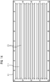
- the figure 3 shows a to the embodiment of figure 1 alternative exemplary embodiment for an energy storage module 10, in which the two side walls 41, 42 and one end wall 43 are provided with grooves 70, viewed from the edge region RB of the respective wall.
- the longitudinal direction of the grooves 70 in turn extends perpendicular to the plane of the image figure 3 and forms a preferred direction of fluid flow.
- the wall areas 411, 421 and 431 are formed by deep-drawn metal sheets.
- the figure 4 shows a variant of the embodiment according to FIG figure 3 , in which a circulation device 60 is additionally arranged inside the housing 40 of the energy storage module 10, which, during operation of the energy storage module 10 and in particular during a charging or discharging process of the storage cells 20, 30, circulates a fluid located inside the housing 40 for the purpose of cooling or cooling the Storage cells 20 and 30 circulated.
- a circulation device 60 is additionally arranged inside the housing 40 of the energy storage module 10, which, during operation of the energy storage module 10 and in particular during a charging or discharging process of the storage cells 20, 30, circulates a fluid located inside the housing 40 for the purpose of cooling or cooling the Storage cells 20 and 30 circulated.
- the figure 5 shows another embodiment of an energy storage module 10 according to the invention, in a perspective view.
- the side wall areas 411 and 421 of the cuboid housing 40 are provided with grooves 70 which enable or simplify heat dissipation from the interior of the housing 40 to the outside.
- the above explanations apply in connection with the Figures 1 to 4 in the embodiment according to figure 5 corresponding.
- the two further side walls that are not visible in the view can also have corresponding side wall areas with grooves for enlarging the housing surface.
- FIG 6 shows another embodiment of an energy storage module 10 according to the invention, in a perspective view. It is clear from this representation that in addition to the two side wall areas 411 and 421, an end wall area 431 of the end wall 44, which is opposite the end wall 43 carrying the connection contacts 11, 12, is also provided with grooves 70.
- FIG. 1 shows a rail vehicle 100 that is equipped with two energy storage modules 10.
- FIG. At the in the figure 7 left energy storage module 10 is an example of an energy storage module, as in connection with the figure 1 has been explained, while the right energy storage module 10 is an energy storage module as it related to the figure 3 has been explained.
- the rail vehicle 10 is additionally equipped with one or more fans 110 which cause a fluid flow or air flow in the interior of the rail vehicle 100 close to the housing in order to cool the energy storage modules 10 .
- the figure 8 shows an embodiment of a rail vehicle 100, in which an energy storage module 10, which is, for example, one of the Figures 1 to 6 energy storage modules shown, is arranged in the area of the roof or a side or bottom wall of rail vehicle 100 in such a way that ribs 50 or grooves 70 in housing wall areas of housing 40 are cooled by the outside air, in particular the relative wind when rail vehicle 100 is moving.
- the side walls or the ribs 50 or grooves 70 of the side wall areas thus form sections of an outer skin 101 of the rail vehicle 100.
- the figure 9 shows a further variant of the embodiment according to FIG figure 8 .
- a fan 110 is additionally provided in the interior of the rail vehicle 100, which cools the side wall or end wall regions of the housing 40 located in the interior of the rail vehicle.
- the figure 10 shows a possible alternative configuration for a side wall or end wall of a housing, the cross section or profile of which, viewed from the plane of the edge region RB, has outwardly extending trapezoidal ribs 50 with flat roof regions 51 lying on the outside.
- the figure 11 shows a further possible alternative configuration for a side wall or end wall, in which both outwardly protruding ribs 50 and inwardly protruding Grooves 70 are provided to increase the surface area of the housing.
- FIG. 12 shows another possible alternative configuration for a side wall or end wall which is clad or coated on its inside with an electrically insulating, thermally conductive material 300.
- FIG. The insulation material 300 rests on the inside of the housing wall 41 without a gap.
- FIG. 12 shows a further possible alternative configuration for a side wall or front wall, in which the inside is also lined with an electrically insulating material 300.
- FIG. The material 300 is in turn clad or coated with an electrically conductive material 310 on its side facing away from the wall area.
- the electrically conductive material 310, the electrically insulating, thermally conductive material 300 and the wall area together form a cross section corresponding to a sandwich structure 320.
- the figure 14 shows a plan view of in FIG figure 5 illustrated side wall 41 of the housing 40 or the side wall area 411 of this side wall 41.
- the side wall area 411 has a cross section corresponding to the exemplary embodiment of FIG figure 10 on, whereby trapezoidal ribs 50 are formed.
Landscapes
- Engineering & Computer Science (AREA)
- Manufacturing & Machinery (AREA)
- Chemical & Material Sciences (AREA)
- Chemical Kinetics & Catalysis (AREA)
- Electrochemistry (AREA)
- General Chemical & Material Sciences (AREA)
- Secondary Cells (AREA)
Abstract
Ein Energiespeichermodul weist zumindest ein quaderförmiges Gehäuse mit vier Seitenwänden und zwei Stirnwänden auf, in welchem zumindest zwei Speicherzellen angeordnet sind. Kennzeichnend sind zumindest zwei der Seitenwände des Gehäuses aus einem thermisch leitfähigen Material hergestellt und weisen jeweils zumindest einen Seitenwandbereich mit einem wellenförmigen Querschnitt sowohl der Außenseite als auch der Innenseite der Seitenwand auf.An energy storage module has at least one cuboid housing with four side walls and two end walls, in which at least two storage cells are arranged. Typically, at least two of the side walls of the housing are made of a thermally conductive material and each has at least one side wall portion with a corrugated cross-section on both the outside and inside of the side wall.
Description
Die Erfindung betrifft ein Energiespeichermodul mit einem quaderförmigen Gehäuse sowie zumindest zwei darin angeordneten Speicherzellen.The invention relates to an energy storage module with a cuboid housing and at least two storage cells arranged therein.
Eine beispielhafte Energiespeichereinrichtung ist in der US-Schrift
Der Erfindung liegt die Aufgabe zugrunde, ein Energiespeichermodul anzugeben, welches eine zuverlässige Wärmeabfuhr an die Umgebung des Gehäuses gewährleistet und ein Überhitzen der Energiespeichermoduls in einfacher Weise vermeiden kann.The invention is based on the object of specifying an energy storage module which ensures reliable heat dissipation to the surroundings of the housing and can easily prevent the energy storage module from overheating.
Diese Aufgabe wird durch ein Energiespeichermodul sowie ein Fahrzeug mit zumindest einem solchen Energiespeichermodul gemäß den Merkmalen der unabhängigen Patentansprüche gelöst. Weiterbildungen sind in jeweiligen abhängigen Patentansprüchen angegeben.This object is achieved by an energy storage module and a vehicle with at least one such energy storage module according to the features of the independent patent claims. Further developments are specified in the respective dependent patent claims.
Danach ist erfindungsgemäß vorgesehen, dass ein Energiespeichermodul zumindest ein quaderförmiges Gehäuse mit vier Seitenwänden und zwei Stirnwänden aufweist, in welchem zumindest zwei Speicherzellen angeordnet sind. Kennzeichnend sind zumindest zwei der Seitenwände des Gehäuses aus einem thermisch leitfähigen Material hergestellt und weisen jeweils zumindest einen Seitenwandbereich mit einem wellenförmigen Querschnitt sowohl der Außenseite als auch der Innenseite der Seitenwand auf.Accordingly, it is provided according to the invention that an energy storage module has at least one cuboid housing with four side walls and two end walls, in which at least two storage cells are arranged. Typically, at least two of the side walls of the housing are made of a thermally conductive material and each has at least one side wall portion with a corrugated cross-section on both the outside and inside of the side wall.
Ein Vorteil des erfindungsgemäßen Energiespeichermoduls ist darin zu sehen, dass durch den wellenförmigen Querschnitt der Seitenwandbereiche eine Oberflächenvergrößerung des Gehäuses erzielt wird, welche eine Wärmeabfuhr nach außen bzw. an die Umgebungsatmosphäre des Gehäuses ermöglichen, ohne besondere Kühleinrichtungen wie beispielsweise Kühlfinnen oder eine gesonderte mit dem Gehäuse thermisch verbundene Kühlplatte vorsehen zu müssen.An advantage of the energy storage module according to the invention can be seen in the fact that the wavy cross section of the side wall areas increases the surface area of the housing, which allows heat to be dissipated to the outside or to the atmosphere surrounding the housing without special cooling devices such as cooling fins or a separate one having to provide a cooling plate thermally connected to the housing.
Vorzugsweise weist das quaderförmige Gehäuse an drei oder mehr Quaderteilflächen bzw. Seitenwänden jeweils zumindest einen Seitenwandbereich mit einem wellenförmigen Querschnitt auf.The cuboid housing preferably has at least one side wall area with a corrugated cross section on three or more partial cuboid surfaces or side walls.
Gemäß einer Weiterbildung liegt jeder Erhöhung auf der Außenseite des Seitenwandbereichs eine korrespondierende Vertiefung auf der Innenseite des Seitenwandbereichs gegenüber, und liegt jeder Vertiefung auf der Außenseite des Seitenwandbereichs eine korrespondierende Erhöhung auf der Innenseite des Seitenwandbereichs gegenüber.According to a development, each elevation on the outside of the side wall area is opposite a corresponding depression on the inside of the side wall area, and each depression on the outside of the side wall area is opposite a corresponding elevation on the inside of the side wall area.
Gemäß einer weiteren Weiterbildung ist die Wandstärke in den Seitenwandbereichen konstant.According to a further development, the wall thickness is constant in the side wall areas.
Gemäß einer weiteren Weiterbildung ist der wellenförmige Querschnitt der Seitenwandbereiche durch Materialumformung des thermisch leitfähigen Materials, insbesondere mittels eines Tiefziehverfahrens, gebildet worden.According to a further development, the wavy cross section of the side wall areas has been formed by material deformation of the thermally conductive material, in particular by means of a deep-drawing process.
Vorzugsweise alle vier Seitenwände sowie gegebenenfalls ergänzend die Stirnwände sind dabei aus einem oder mehreren Metallblechen gefertigt, welche ganz oder in Abschnitten tiefgezogen sind. Als Metallbleche eignen sich dabei beispielsweise Bleche aus einem Aluminium- oder Edelstahlmaterial.Preferably, all four side walls and possibly also the end walls are made from one or more metal sheets, which are deep-drawn in whole or in sections. In this case, for example, metal sheets made of an aluminum or stainless steel material are suitable as metal sheets.
Gemäß einer weiteren Weiterbildung sind die zumindest zwei Seitenwände jeweils randseitig plan und weisen in ihrem Innenbereich jeweils zumindest einen Seitenwandbereich auf, wobei die Seitenwandbereiche jeweils von einem planen umlaufenden Randbereich der Seitenwand umschlossen sind.According to a further development, the at least two side walls are each flat at the edge and each have at least one side wall area in their inner area, with the side wall areas each being surrounded by a flat peripheral edge area of the side wall.
Die Seitenwände sind vorzugsweise jeweils winklig zu einem oder mehreren benachbarten Seitenwänden und Stirnwänden angeordnet.The side walls are preferably each arranged at an angle to one or more adjacent side walls and end walls.
Benachbarte Seitenwände können durch ein gemeinsamen Element, beispielsweise ein gemeinsames Blech, gebildet sein, das an ein oder mehr Biegekanten umgebogen ist. Die Biegekanten segmentieren in diesem Fall das gemeinsame Element in benachbarte Seitenwände des Gehäuses.Adjacent side walls can be formed by a common element, for example a common metal sheet, which is bent at one or more bending edges. In this case, the bending edges segment the common element into adjacent side walls of the housing.
Alternativ können benachbarte Seitenwände auch durch separate Gehäuseteile, beispielsweise in Form von Einzelblechen, gebildet sein, die winklig aneinandergesetzt und miteinander verbunden, vorzugsweise verschweißt, verschraubt und/oder vernietet, worden sind.Alternatively, adjacent side walls can also be formed by separate housing parts, for example in the form of individual metal sheets, which are placed together at an angle and connected to one another, preferably welded, screwed and/or riveted.
Wird das Gehäuse durch separate Gehäuseteile gebildet, so werden diese vorzugsweise lückenlos bzw. fluiddicht miteinander verbunden, um ein hermetisch dichtes Gehäuse zu bilden.If the housing is formed by separate housing parts, these are preferably connected to one another without gaps or in a fluid-tight manner in order to form a hermetically sealed housing.
Aneinander angrenzende Gehäuseteile können im Schnittstellenbereich bzw. im Bereich ihrer Berührungskanten plan, gefalzt, gebördelt oder mit einer Nut versehen sein.Adjoining housing parts can be flat, folded, beaded or provided with a groove in the interface area or in the area of their contact edges.
Gemäß einer weiteren Weiterbildung weisen die Seitenwandbereiche jeweils Rippen und/oder Nuten bzw. Rinnen auf, welche sich parallel entlang einer vorgegebenen Fluidstromrichtung erstrecken.According to a further development, the side wall areas each have ribs and/or grooves or grooves, which extend in parallel along a predetermined fluid flow direction.
Gemäß einer weiteren Weiterbildung ist zumindest die Innenseite der Seitenwandbereiche jeweils mit einem elektrisch isolierenden, jedoch thermisch leitfähigen Material verkleidet oder beschichtet, welches auf der Innenseite spaltfrei anliegt. Das elektrisch isolierende Material dient dabei vorzugsweise einer elektrischen Trennung der Speicherzellen vom Gehäuse.According to a further development, at least the inside of the side wall areas is lined or coated with an electrically insulating but thermally conductive material, which rests on the inside without a gap. In this case, the electrically insulating material preferably serves to electrically isolate the storage cells from the housing.
Gemäß einer auf der voranstehenden Weiterbildung basierenden weiteren Weiterbildung ist das Material auf seiner von dem Seitenwandbereich abgewandten Seite mit einem elektrisch leitfähigen Material verkleidet oder beschichtet, welches auf dem elektrisch isolierenden, thermisch leitfähigen Material spaltfrei anliegt, wobei der Seitenwandbereich, das elektrisch isolierende, thermisch leitfähige Material und das elektrisch leitfähige Material eine Sandwichstruktur ausbilden.According to a further development based on the above development, the side of the material facing away from the side wall area is lined or coated with an electrically conductive material, which rests without a gap on the electrically insulating, thermally conductive material, with the side wall area being the electrically insulating, thermally conductive Material and the electrically conductive material form a sandwich structure.
Bei einer solchen Sandwichstruktur weist das elektrisch leitfähige Material bzw. die dadurch gebildete Innenverkleidung vorzugsweise keinen elektrischen Kontakt zur Seitenwand des Gehäuses äußeren Gehäusewand auf. Eine Innenverkleidung oder Sandwichstruktur kann in vorteilhafter Weise lokale Temperaturerhöhungen bzw. so genannte Hotspots vermeiden und so zu einer verbesserten Gesamtwärmeabfuhr führen.With such a sandwich structure, the electrically conductive material or the interior lining formed thereby preferably has no electrical contact with the side wall of the housing, the outer housing wall. An interior lining or sandwich structure can advantageously avoid local increases in temperature or so-called hotspots and thus lead to improved overall heat dissipation.
Gemäß einer weiteren Weiterbildung ist zwischen zumindest einer der Speicherzellen und der Innenseite des Seitenwandbereichs, dem elektrisch isolierenden, thermisch leitfähigen Material oder dem elektrisch leitfähigem Material zumindest ein elektrisch isolierender Abstandshalter für eine mechanische Trennung der zumindest einen Speicherzelle von dem Gehäuse angeordnet.According to a further development, at least one electrically insulating spacer for mechanically separating the at least one storage cell from the housing is arranged between at least one of the storage cells and the inside of the side wall area, the electrically insulating, thermally conductive material or the electrically conductive material.
Dabei kann ein solcher Abstandshalter alternativ zu einer Verkleidung der Innenseite eines Seitenwandbereichs mit einem elektrisch isolierenden, thermisch leitfähigen Material vorgesehen werden.In this case, such a spacer can be provided as an alternative to covering the inside of a side wall area with an electrically insulating, thermally conductive material.
Vorteilhaft können mittels solcher Abstandshalter im Inneren des Gehäuses Fluidkanäle gebildet werden, welche einen Fluidstrom im Bereich der Innenseiten des Gehäuses ermöglichen.Advantageously, such spacers can be used to form fluid channels in the interior of the housing, which allow fluid to flow in the area of the inner sides of the housing.
Gemäß einer weiteren Weiterbildung ist in dem Gehäuse eine Umwälzeinrichtung angeordnet, welche einer Umwälzung eines Fluids im Inneren des Gehäuses dient. Hierdurch kann vorteilhaft eine homogene Verteilung der von den Speicherzellen ausgehenden Wärme innerhalb des geschlossenen Gehäuses erzielt werden. Eine solche Umwälzeinrichtung kann beispielsweise als ein Lüfter ausgestaltet sein, wenn als Fluid Luft in dem Gehäuse umgewälzt wird.According to a further development, a circulation device is arranged in the housing, which serves to circulate a fluid inside the housing. This can be beneficial a homogeneous distribution of the heat emanating from the storage cells can be achieved within the closed housing. Such a circulating device can be designed, for example, as a fan if air is circulated in the housing as the fluid.
Gemäß einer weiteren Weiterbildung weist ergänzend zumindest eine der Stirnwände des Gehäuses einen Stirnwandbereich mit einem wellenförmigen Querschnitt sowohl der Außenseite als auch der Innenseite der Stirnwand auf, wobei der jeweilige Stirnwandbereich insbesondere entsprechend einem Seitenwandbereich gemäß einem oder mehreren der vorstehend beschriebenen Ausgestaltungen der Seitenwandbereiche ausgestaltet ist.According to a further development, at least one of the end walls of the housing additionally has an end wall area with a wavy cross-section both on the outside and on the inside of the end wall, with the respective end wall area being designed in particular to correspond to a side wall area according to one or more of the configurations of the side wall areas described above.
Ein erfindungsgemäßes Fahrzeug, insbesondere ein Schienenfahrzeug, weist zumindest ein erfindungsgemäßes Energiespeichermodul auf.A vehicle according to the invention, in particular a rail vehicle, has at least one energy storage module according to the invention.
Gemäß einer Weiterbildung des Fahrzeugs weist das Fahrzeug ferner eine Umwälzeinrichtung, insbesondere einen Lüfter, auf, welche derart ausgerichtet ist, dass ein von ihr erzeugter Fluidstrom entlang einer Längsrichtung von Rippen und/oder Nuten der Seitenwandbereiche ausgerichtet ist.According to a development of the vehicle, the vehicle also has a circulation device, in particular a fan, which is aligned such that a fluid flow it generates is aligned along a longitudinal direction of ribs and/or grooves of the side wall regions.
Gemäß einer weiteren Weiterbildung des Fahrzeugs sind die Rippen und/oder Nuten parallel zu einer Längsrichtung des Fahrzeugs ausgerichtet.According to a further development of the vehicle, the ribs and/or grooves are aligned parallel to a longitudinal direction of the vehicle.
Zumindest eine der Seitenwände bzw. der Seitenwandbereiche kann einen Abschnitt der Außenhaut des Fahrzeugs bilden.At least one of the side walls or the side wall areas can form a section of the outer skin of the vehicle.
Die Erfindung wird nachfolgend anhand von Ausführungsbeispielen näher erläutert. Dabei zeigen beispielhaft
- Fig. 1
- ein Ausführungsbeispiel für ein erfindungsgemäßes Energiespeichermodul mit Rippen,
- Fig. 2
- ein Ausführungsbeispiel für ein erfindungsgemäßes Energiespeichermodul mit Rippen und Umwälzeinrichtung,
- Fig. 3
- ein Ausführungsbeispiel für ein erfindungsgemäßes Energiespeichermodul mit Nuten,
- Fig. 4
- ein Ausführungsbeispiel für ein erfindungsgemäßes Energiespeichermodul mit Nuten und Umwälzeinrichtung,
- Fig. 5
- ein Ausführungsbeispiel für ein erfindungsgemäßes quaderförmiges Energiespeichermodul in einer perspektivischen Ansicht,
- Fig. 6
- ein weiteres Ausführungsbeispiel für ein erfindungsgemäßes quaderförmiges Energiespeichermodul in einer perspektivischen Ansicht,
- Fig. 7-9
- Ausführungsbeispiele für erfindungsgemäße Schienenfahrzeuge, die mit Ausführungsbeispielen für erfindungsgemäße Energiespeichermodule ausgestattet sind, und
- Fig. 10-14
- Ausführungsbeispiele für Querschnitte von Seiten- bzw. Stirnwänden für erfindungsgemäße Energiespeichermodule.
- 1
- an embodiment of an energy storage module according to the invention with ribs,
- 2
- an embodiment of an energy storage module according to the invention with ribs and circulating device,
- 3
- an embodiment of an energy storage module according to the invention with grooves,
- 4
- an embodiment of an energy storage module according to the invention with grooves and circulating device,
- figure 5
- an embodiment of a cuboid energy storage module according to the invention in a perspective view,
- 6
- a further exemplary embodiment of a cuboid energy storage module according to the invention in a perspective view,
- Figures 7-9
- Exemplary embodiments for rail vehicles according to the invention, which are equipped with exemplary embodiments for energy storage modules according to the invention, and
- Figures 10-14
- Exemplary embodiments for cross sections of side and end walls for energy storage modules according to the invention.
In den Figuren werden der Übersicht halber für identische oder vergleichbare Elemente dieselben Bezugszeichen verwendet.In the figures, for the sake of clarity, the same reference numbers are used for identical or comparable elements.
Die
Die Speicherzellen 20 und 30 sind in einem gemeinsamen Gehäuse 40 untergebracht, dessen Gehäusewände 41, 42, 43 und 44 die beiden Speicherzellen 20 und 30 umgeben bzw. umschließen.The
Alle oder einige Gehäusewände 41, 42, 43 des Gehäuses 40 weisen Gehäusewandbereiche 411, 421, 431 auf, die eine Wärmeabfuhr an die Umgebung des Gehäuses 40 des Energiespeichermoduls 10 bzw. eine Kühlung der Speicherzellen 20, 30 ermöglichen.All or some of the
In dem schematischen Querschnitt gemäß
Bei den wellenförmigen Seitenwandbereichen 411, 421 bzw. Stirnwandbereich 431 ist jeweils die außenseitige Formgestaltung komplementär zu der innenseitigen Formgestaltung ausgestaltet. So lässt sich in der
Beispielsweise für eine mechanische Befestigung und einer elektrischen Isolation der Speicherzellen 20 und 30 am bzw. vom Gehäuse 40 sind Abstandshalter 55 vorgesehen, die vorzugsweise aus elektrisch nicht leitendem, jedoch thermisch leitendem Material bestehen. Die Abstandshalter 55 können auch weggelassen werden, wenn beispielsweise die Speicherzellen 20 und 30 direkt an einer Gehäusewand anliegen oder von dieser gehalten werden sollen.For example, spacers 55 are provided for mechanical attachment and electrical insulation of
Bei dem Ausführungsbeispiel gemäß
In der Ausführungsvariante gemäß
Die
Die
Die
Die
Die
Vorteilhaft ist es, wenn das Schienenfahrzeug 10 zusätzlich mit einem oder mehreren Lüftern 110 ausgestattet ist, die zum Kühlen der Energiespeichermodule 10 einen gehäusenahen Fluidstrom bzw. Luftstrom im Inneren des Schienenfahrzeugs 100 hervorrufen.It is advantageous if the
Die
Die
Die
Die
Die
Die
Die
Claims (14)
zumindest aufweisend:
at least having:
dadurch gekennzeichnet, dass
characterized in that
dadurch gekennzeichnet, dass
die Wandstärke in den Seitenwandbereichen (411, 421) jeweils konstant ist.Energy storage module (10) according to claim 1 or 2,
characterized in that
the wall thickness in the side wall areas (411, 421) is constant in each case.
dadurch gekennzeichnet, dass
der wellenförmige Querschnitt der Seitenwandbereiche (411, 421) durch Materialumformung des thermisch leitfähigen Materials, insbesondere mittels eines Tiefziehverfahrens, gebildet worden ist.Energy storage module (10) according to any one of the preceding claims,
characterized in that
the wavy cross section of the side wall areas (411, 421) has been formed by material deformation of the thermally conductive material, in particular by means of a deep-drawing process.
dadurch gekennzeichnet, dass
die zumindest zwei Seitenwände (41, 42) jeweils randseitig plan sind und in ihrem Innenbereich jeweils zumindest einen Seitenwandbereich (411, 421) aufweisen, wobei die Seitenwandbereiche (411, 421) jeweils von einem planen umlaufenden Randbereich (RB) der Seitenwand (41, 42) umschlossen sind.Energy storage module (10) according to any one of the preceding claims,
characterized in that
the at least two side walls (41, 42) are each flat on the edge and each have at least one side wall area (411, 421) in their inner area, wherein the side wall areas (411, 421) each extend from a flat peripheral edge area (RB) of the side wall (41, 42) are enclosed.
dadurch gekennzeichnet, dass
die Seitenwandbereiche (411, 421) jeweils Rippen (50) und/oder Nuten (70) aufweisen, welche sich parallel entlang einer vorgegebenen Fluidstromrichtung erstrecken.Energy storage module (10) according to any one of the preceding claims,
characterized in that
the side wall regions (411, 421) each have ribs (50) and/or grooves (70) which extend in parallel along a predetermined fluid flow direction.
dadurch gekennzeichnet, dass
die Innenseiten (I) zumindest der Seitenwandbereiche (411, 421) jeweils mit einem elektrisch isolierenden, jedoch thermisch leitfähigen Material (300) verkleidet oder beschichtet ist, welches auf der Innenseite (I) spaltfrei anliegt.Energy storage module (10) according to any one of the preceding claims,
characterized in that
the inner sides (I) of at least the side wall areas (411, 421) are each lined or coated with an electrically insulating but thermally conductive material (300) which lies on the inner side (I) without a gap.
dadurch gekennzeichnet, dass
das Material (300) auf seiner dem Seitenwandbereich (411, 421) abgewandten Seite mit einem elektrisch leitfähigen Material (310) verkleidet oder beschichtet ist, welches auf dem elektrisch isolierenden, thermisch leitfähigen Material (300) spaltfrei anliegt, wobei der Seitenwandbereich (411, 421), das elektrisch isolierende, thermisch leitfähige Material (300) und das elektrisch leitfähige Material (310) eine Sandwichsstruktur (320) ausbilden.Energy storage module (10) according to claim 7,
characterized in that
the material (300) is clad or coated on its side facing away from the side wall area (411, 421) with an electrically conductive material (310) which lies on the electrically insulating, thermally conductive material (300) without a gap, the side wall area (411, 421), the electrically insulating, thermally conductive material (300) and the electrically conductive material (310) form a sandwich structure (320).
dadurch gekennzeichnet, dass
zwischen zumindest einer der Speicherzellen (20, 30) und der Innenseite (I) des Seitenwandbereichs (411, 421), dem elektrisch isolierenden, thermisch leitfähigen Material (300) oder dem elektrisch leitfähigem Material (310) zumindest ein elektrisch isolierender Abstandshalter (55) für eine mechanische Trennung der zumindest einen Speicherzelle (20, 30) von dem Gehäuse (40) angeordnet ist.Energy storage module (10) according to claim 7 or 8
characterized in that
at least one electrically insulating spacer (55) between at least one of the storage cells (20, 30) and the inside (I) of the side wall area (411, 421), the electrically insulating, thermally conductive material (300) or the electrically conductive material (310) is arranged for a mechanical separation of the at least one storage cell (20, 30) from the housing (40).
dadurch gekennzeichnet, dass
in dem Gehäuse (40) eine Umwälzeinrichtung (60) angeordnet ist, welche einer Umwälzung eines Fluids im Inneren des Gehäuses (40) dient.Energy storage module (10) according to any one of the preceding claims,
characterized in that
a circulation device (60) is arranged in the housing (40) and serves to circulate a fluid inside the housing (40).
dadurch gekennzeichnet, dass
zumindest eine der Stirnwände (43, 43) einen Stirnwandbereich (431, 441) mit einem wellenförmigen Querschnitt sowohl der Außenseite (A) als auch der Innenseite (I) der Stirnwand (43, 44) aufweist, wobei der jeweilige Stirnwandbereich (431, 441) insbesondere entsprechend einem Seitenwandbereich (411, 421) gemäß den Ansprüchen 2 bis 10 ausgestaltet ist .Energy storage device according to one of the preceding claims,
characterized in that
at least one of the end walls (43, 43) has an end wall area (431, 441) with a corrugated cross-section both on the outside (A) and on the inside (I) of the end wall (43, 44), the respective end wall area (431, 441 ) is designed in particular according to a side wall area (411, 421) according to claims 2 to 10.
dadurch gekennzeichnet, dass
es zumindest ein Energiespeichermodul (10) nach einem der voranstehenden Ansprüche aufweist.Vehicle, in particular rail vehicle (100),
characterized in that
it has at least one energy storage module (10) according to any one of the preceding claims.
dadurch gekennzeichnet, dass
das Fahrzeug zumindest eine Umwälzeinrichtung (110), insbesondere zumindest einen Lüfter, aufweist, welche derart ausgerichtet ist, dass ein von ihr erzeugter Fluidstrom entlang einer Längsrichtung von Rippen (50) und/oder Nuten (70) der Seitenwandbereiche (411, 421) ausgerichtet ist.Vehicle according to claim 12,
characterized in that
the vehicle has at least one circulation device (110), in particular at least one fan, which is aligned in such a way that a fluid flow it generates is aligned along a longitudinal direction of ribs (50) and/or grooves (70) of the side wall regions (411, 421). is.
dadurch gekennzeichnet, dass
in den Seitenwandbereichen (411, 421) ausgebildete Rippen (50) und/oder Nuten (70) parallel zu einer Längsrichtung des Fahrzeugs ausgerichtet sind.Vehicle according to claim 12 or 13,
characterized in that
ribs (50) and/or grooves (70) formed in the side wall portions (411, 421) are aligned parallel to a longitudinal direction of the vehicle.
Applications Claiming Priority (1)
| Application Number | Priority Date | Filing Date | Title |
|---|---|---|---|
| DE102021202115.8A DE102021202115A1 (en) | 2021-03-04 | 2021-03-04 | Energy storage device with storage cell |
Publications (2)
| Publication Number | Publication Date |
|---|---|
| EP4053973A1 true EP4053973A1 (en) | 2022-09-07 |
| EP4053973B1 EP4053973B1 (en) | 2024-05-22 |
Family
ID=80461214
Family Applications (1)
| Application Number | Title | Priority Date | Filing Date |
|---|---|---|---|
| EP22158568.0A Active EP4053973B1 (en) | 2021-03-04 | 2022-02-24 | Energy storage module |
Country Status (2)
| Country | Link |
|---|---|
| EP (1) | EP4053973B1 (en) |
| DE (1) | DE102021202115A1 (en) |
Citations (5)
| Publication number | Priority date | Publication date | Assignee | Title |
|---|---|---|---|---|
| JP2015106527A (en) * | 2013-12-02 | 2015-06-08 | サーチウェア株式会社 | Battery pack and mobile mounting the same |
| US20180301773A1 (en) | 2016-01-15 | 2018-10-18 | Murata Manufacturing Co., Ltd. | Battery pack |
| US20190115638A1 (en) * | 2016-04-01 | 2019-04-18 | A123 Systems Llc | Battery module with heat dissipating encapsulant material and methods therefor |
| US20200006825A1 (en) * | 2018-06-28 | 2020-01-02 | Hyundai Motor Company | Battery module for vehicle |
| DE102019108386A1 (en) * | 2019-04-01 | 2020-10-01 | Bayerische Motoren Werke Aktiengesellschaft | Battery with holding device and motor vehicle |
Family Cites Families (4)
| Publication number | Priority date | Publication date | Assignee | Title |
|---|---|---|---|---|
| DE102011000353A1 (en) | 2011-01-27 | 2012-08-02 | Dr. Ing. H.C. F. Porsche Aktiengesellschaft | battery |
| DE102011086049A1 (en) | 2011-11-10 | 2013-05-16 | Sb Limotive Company Ltd. | Battery i.e. medium power battery, for use in e.g. hybrid vehicle, has intake opening and exhaust opening arranged in inner housing spaced apart from battery housing such that airflow is produced between inner and battery housings |
| CN104466303B (en) | 2013-09-24 | 2017-09-29 | 微宏动力系统(湖州)有限公司 | Phase transformation battery pack |
| KR20210077676A (en) | 2018-09-11 | 2021-06-25 | 에너자이저 브랜즈, 엘엘씨 | Hearing aid battery with slotted grommets |
-
2021
- 2021-03-04 DE DE102021202115.8A patent/DE102021202115A1/en active Pending
-
2022
- 2022-02-24 EP EP22158568.0A patent/EP4053973B1/en active Active
Patent Citations (5)
| Publication number | Priority date | Publication date | Assignee | Title |
|---|---|---|---|---|
| JP2015106527A (en) * | 2013-12-02 | 2015-06-08 | サーチウェア株式会社 | Battery pack and mobile mounting the same |
| US20180301773A1 (en) | 2016-01-15 | 2018-10-18 | Murata Manufacturing Co., Ltd. | Battery pack |
| US20190115638A1 (en) * | 2016-04-01 | 2019-04-18 | A123 Systems Llc | Battery module with heat dissipating encapsulant material and methods therefor |
| US20200006825A1 (en) * | 2018-06-28 | 2020-01-02 | Hyundai Motor Company | Battery module for vehicle |
| DE102019108386A1 (en) * | 2019-04-01 | 2020-10-01 | Bayerische Motoren Werke Aktiengesellschaft | Battery with holding device and motor vehicle |
Also Published As
| Publication number | Publication date |
|---|---|
| DE102021202115A1 (en) | 2022-09-08 |
| EP4053973B1 (en) | 2024-05-22 |
Similar Documents
| Publication | Publication Date | Title |
|---|---|---|
| DE102012012294B4 (en) | Vehicle with a battery assembly | |
| DE102007010744B4 (en) | Battery cell of a battery, cell combination of battery cells and use of multiple cells | |
| EP1835251B1 (en) | Device for cooling electrical elements | |
| EP2497145B1 (en) | Energy store device | |
| DE112018002536T5 (en) | COUNTERFLOW HEAT EXCHANGER WITH SIDE INLET FITTINGS | |
| DE102017128529A1 (en) | Motor vehicle battery | |
| EP2567423B1 (en) | Battery cooling device | |
| WO2018024483A1 (en) | Temperature-control device for a battery housing of a vehicle | |
| DE102007010742A1 (en) | Cell composite for lithium ion battery, has battery cells that are fixed by sealing compound and are arranged parallel to each other in longitudinal axes, and form closure formed with sealing compound in outer side of battery cells | |
| DE112007002809T5 (en) | Electric power supply system | |
| EP3378111B1 (en) | Battery array | |
| DE102008034873A1 (en) | Battery i.e. automotive lithium ion battery, for e.g. motor vehicle, has cells connected with each other in series and/or parallel, and cooling element formed as sink with recesses, where cells are arranged in extension in recesses | |
| DE102017219176A1 (en) | Battery module for a high-voltage battery of a motor vehicle, high-voltage battery and motor vehicle | |
| DE102015118747A1 (en) | Cooling module for a battery, battery for a vehicle and method for manufacturing a cooling module | |
| DE102017005400A1 (en) | Energy storage arrangement and motor vehicle | |
| DE102017005315A1 (en) | battery box | |
| DE102017005401A1 (en) | Modular system and motor vehicle | |
| DE102021110496A1 (en) | BATTERY PACK MODULE | |
| DE60212504T2 (en) | Cooling device on the housing of a secondary battery | |
| DE102017009640A1 (en) | cooler | |
| DE112016005977B4 (en) | Connection module | |
| EP4053973B1 (en) | Energy storage module | |
| DE102018215580A1 (en) | Cell housing for a battery cell of a high-voltage battery, battery cell, high-voltage battery and motor vehicle | |
| DE102021118397A1 (en) | Battery with integrated busbar cooling and motor vehicle | |
| DE102021202709A1 (en) | Battery module and method for manufacturing a battery module |
Legal Events
| Date | Code | Title | Description |
|---|---|---|---|
| PUAI | Public reference made under article 153(3) epc to a published international application that has entered the european phase |
Free format text: ORIGINAL CODE: 0009012 |
|
| STAA | Information on the status of an ep patent application or granted ep patent |
Free format text: STATUS: THE APPLICATION HAS BEEN PUBLISHED |
|
| AK | Designated contracting states |
Kind code of ref document: A1 Designated state(s): AL AT BE BG CH CY CZ DE DK EE ES FI FR GB GR HR HU IE IS IT LI LT LU LV MC MK MT NL NO PL PT RO RS SE SI SK SM TR |
|
| STAA | Information on the status of an ep patent application or granted ep patent |
Free format text: STATUS: REQUEST FOR EXAMINATION WAS MADE |
|
| 17P | Request for examination filed |
Effective date: 20230303 |
|
| RBV | Designated contracting states (corrected) |
Designated state(s): AL AT BE BG CH CY CZ DE DK EE ES FI FR GB GR HR HU IE IS IT LI LT LU LV MC MK MT NL NO PL PT RO RS SE SI SK SM TR |
|
| GRAP | Despatch of communication of intention to grant a patent |
Free format text: ORIGINAL CODE: EPIDOSNIGR1 |
|
| STAA | Information on the status of an ep patent application or granted ep patent |
Free format text: STATUS: GRANT OF PATENT IS INTENDED |
|
| INTG | Intention to grant announced |
Effective date: 20240105 |
|
| GRAS | Grant fee paid |
Free format text: ORIGINAL CODE: EPIDOSNIGR3 |
|
| GRAA | (expected) grant |
Free format text: ORIGINAL CODE: 0009210 |
|
| STAA | Information on the status of an ep patent application or granted ep patent |
Free format text: STATUS: THE PATENT HAS BEEN GRANTED |
|
| AK | Designated contracting states |
Kind code of ref document: B1 Designated state(s): AL AT BE BG CH CY CZ DE DK EE ES FI FR GB GR HR HU IE IS IT LI LT LU LV MC MK MT NL NO PL PT RO RS SE SI SK SM TR |
|
| REG | Reference to a national code |
Ref country code: GB Ref legal event code: FG4D Free format text: NOT ENGLISH |