EP4053953A1 - Electrode assembly and method for manufacturing same - Google Patents
Electrode assembly and method for manufacturing same Download PDFInfo
- Publication number
- EP4053953A1 EP4053953A1 EP20925047.1A EP20925047A EP4053953A1 EP 4053953 A1 EP4053953 A1 EP 4053953A1 EP 20925047 A EP20925047 A EP 20925047A EP 4053953 A1 EP4053953 A1 EP 4053953A1
- Authority
- EP
- European Patent Office
- Prior art keywords
- electrode
- separator
- folded
- cover part
- electrode assembly
- Prior art date
- Legal status (The legal status is an assumption and is not a legal conclusion. Google has not performed a legal analysis and makes no representation as to the accuracy of the status listed.)
- Pending
Links
Images


Classifications
-
- H—ELECTRICITY
- H01—ELECTRIC ELEMENTS
- H01M—PROCESSES OR MEANS, e.g. BATTERIES, FOR THE DIRECT CONVERSION OF CHEMICAL ENERGY INTO ELECTRICAL ENERGY
- H01M10/00—Secondary cells; Manufacture thereof
- H01M10/04—Construction or manufacture in general
- H01M10/045—Cells or batteries with folded plate-like electrodes
- H01M10/0454—Cells or batteries with electrodes of only one polarity folded
-
- H—ELECTRICITY
- H01—ELECTRIC ELEMENTS
- H01M—PROCESSES OR MEANS, e.g. BATTERIES, FOR THE DIRECT CONVERSION OF CHEMICAL ENERGY INTO ELECTRICAL ENERGY
- H01M10/00—Secondary cells; Manufacture thereof
- H01M10/04—Construction or manufacture in general
- H01M10/0459—Cells or batteries with folded separator between plate-like electrodes
-
- H—ELECTRICITY
- H01—ELECTRIC ELEMENTS
- H01M—PROCESSES OR MEANS, e.g. BATTERIES, FOR THE DIRECT CONVERSION OF CHEMICAL ENERGY INTO ELECTRICAL ENERGY
- H01M50/00—Constructional details or processes of manufacture of the non-active parts of electrochemical cells other than fuel cells, e.g. hybrid cells
- H01M50/40—Separators; Membranes; Diaphragms; Spacing elements inside cells
- H01M50/463—Separators, membranes or diaphragms characterised by their shape
- H01M50/466—U-shaped, bag-shaped or folded
-
- H—ELECTRICITY
- H01—ELECTRIC ELEMENTS
- H01M—PROCESSES OR MEANS, e.g. BATTERIES, FOR THE DIRECT CONVERSION OF CHEMICAL ENERGY INTO ELECTRICAL ENERGY
- H01M10/00—Secondary cells; Manufacture thereof
- H01M10/05—Accumulators with non-aqueous electrolyte
- H01M10/052—Li-accumulators
-
- H—ELECTRICITY
- H01—ELECTRIC ELEMENTS
- H01M—PROCESSES OR MEANS, e.g. BATTERIES, FOR THE DIRECT CONVERSION OF CHEMICAL ENERGY INTO ELECTRICAL ENERGY
- H01M10/00—Secondary cells; Manufacture thereof
- H01M10/05—Accumulators with non-aqueous electrolyte
- H01M10/058—Construction or manufacture
- H01M10/0583—Construction or manufacture of accumulators with folded construction elements except wound ones, i.e. folded positive or negative electrodes or separators, e.g. with "Z"-shaped electrodes or separators
-
- Y—GENERAL TAGGING OF NEW TECHNOLOGICAL DEVELOPMENTS; GENERAL TAGGING OF CROSS-SECTIONAL TECHNOLOGIES SPANNING OVER SEVERAL SECTIONS OF THE IPC; TECHNICAL SUBJECTS COVERED BY FORMER USPC CROSS-REFERENCE ART COLLECTIONS [XRACs] AND DIGESTS
- Y02—TECHNOLOGIES OR APPLICATIONS FOR MITIGATION OR ADAPTATION AGAINST CLIMATE CHANGE
- Y02E—REDUCTION OF GREENHOUSE GAS [GHG] EMISSIONS, RELATED TO ENERGY GENERATION, TRANSMISSION OR DISTRIBUTION
- Y02E60/00—Enabling technologies; Technologies with a potential or indirect contribution to GHG emissions mitigation
- Y02E60/10—Energy storage using batteries
-
- Y—GENERAL TAGGING OF NEW TECHNOLOGICAL DEVELOPMENTS; GENERAL TAGGING OF CROSS-SECTIONAL TECHNOLOGIES SPANNING OVER SEVERAL SECTIONS OF THE IPC; TECHNICAL SUBJECTS COVERED BY FORMER USPC CROSS-REFERENCE ART COLLECTIONS [XRACs] AND DIGESTS
- Y02—TECHNOLOGIES OR APPLICATIONS FOR MITIGATION OR ADAPTATION AGAINST CLIMATE CHANGE
- Y02P—CLIMATE CHANGE MITIGATION TECHNOLOGIES IN THE PRODUCTION OR PROCESSING OF GOODS
- Y02P70/00—Climate change mitigation technologies in the production process for final industrial or consumer products
- Y02P70/50—Manufacturing or production processes characterised by the final manufactured product
Definitions
- the present invention relates to an electrode assembly and a method for manufacturing the same, and more particularly, to an electrode assembly that is capable of preventing an electrode from being damaged, such as an occurrence of wrinkles or swells on the electrode due to a taping process or deintercalation of an active material of the electrode and a method for manufacturing the same.
- secondary batteries include nickelcadmium batteries, nickel-hydrogen batteries, lithium ion batteries, and lithium ion polymer batteries.
- Such a secondary battery is being applied to and used in small-sized products such as digital cameras, P-DVDs, MP3Ps, mobile phones, PDAs, portable game devices, power tools, E-bikes, and the like as well as large-sized products requiring high power such as electric vehicles and hybrid vehicles, power storage devices for storing surplus power or renewable energy, and backup power storage devices.
- an electrode assembly is accommodated in a battery case, and an electrolyte is injected, and then, the battery case is sealed. Also, in order to manufacture the electrode assembly, first, positive electrode active material slurry is applied to a positive electrode collector, and negative electrode active material slurry is applied to a negative electrode collector to manufacture a positive electrode and a negative electrode, respectively. A separator is interposed between the positive electrode and the negative electrode to manufacture the electrode assembly.
- Such electrode assemblies are classified into various types.
- the various types of electrode assemblies include a simple stack type electrode assembly, in which positive electrodes, separators, negative electrodes are simply intersected and stacked continuously without manufacturing a unit cell, a lamination & stack (L&S) type electrode assembly, in which unit cells are manufactured first using positive electrodes, separators, and negative electrodes and then are stacked, and a stack & folding (S&F) type, in which a plurality of unit cells are attached at a predetermined interval on one surface of a separator film having a long length and repetitively folded from an one end of the separator film in the same direction.
- L&S lamination & stack
- S&F stack & folding
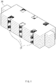
- FIG. 1 is a perspective view of an electrode assembly 30 according to the related art
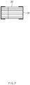
- FIG. 2 is a front view of the electrode assembly 30 according to the related art.
- the existing simple stack type or lamination & stack type electrode assembly 30 has a simple structure and a high degree of impregnation of an electrolyte, but has a problem in that the production speed is slow, and a degree of alignment is lowered.
- a taping process is performed in order to maintain the alignment of the plurality of stacked electrodes and separators of the electrode assembly 30, a taping process is performed. Then, as illustrated in FIG. 1 , the tape 31 is attached to each of both surfaces and portions of the top and bottom surfaces of the electrode assembly 30.
- each of the negative electrode and the separator has a width that is relatively wider than that of the positive electrode. Therefore, since a peripheral portion protrudes to the outside, if the tape 31 is attached, there is a problem in that the electrode is damaged, such as an occurrence of wrinkles or swells or eintercalation of an active material of the electrode.
- the tape 31 may be detached later in an electrolyte injection process or degassing process. Particularly, since a gas within the case has to be discharged to the outside in the degassing process, there is a problem in that the tape 31 is more easily detached by a flow of the gas.
- the stack & folding electrode assembly has a high production speed and high structural stability, but there is a problem in that the process is complicated, and the degree of alignment and the degree of impregnation of the electrolyte are lowered.
- Patent Document 1 Korea Patent Publication No. 2011-0135346
- An object of the prevent invention for solving above problems is to provide an electrode assembly that is capable of preventing an electrode from being damaged, such as an occurrence of wrinkles or swells on the electrode due to a taping process or deintercalation of an active material of the electrode and a method for manufacturing the same.
- An electrode assembly for achieving the above object includes: a first electrode formed in the form of a single sheet and repetitively in-folded and out-folded at a predetermined interval; a second electrode provided in plurality and respectively interposed in spaces formed by folding the first electrode; a separator formed in the form of a single sheet and interposed between the first electrode and the second electrode so as to be repetitively in-folded and out-folded at a predetermined interval together with the first electrode; and a cover part configured to cover at least portions of an area, on which the separator is out-folded and an exposed surface, which is exposed to the outside together with the second electrode.
- the cover part may be formed in the form of a single film.
- both ends of the cover part may be attached to both ends of the first electrode, respectively.
- cover part may be in close contact with the exposed surface.
- the cover part may include at least one of epoxy, polyimide, polyethylene terephthalate (PET), polypropylene (PP), or polytetrafluoroethylene (PTFE).
- epoxy polyimide
- PET polyethylene terephthalate
- PP polypropylene
- PTFE polytetrafluoroethylene
- the first electrode may be a single-sided electrode on which a first electrode active material is applied to only one surface of a first electrode collector
- the second electrode may be a double-sided electrode on which a second electrode active material is applied to both surfaces of a second electrode collector.
- the second electrode may be interposed only in each of spaces formed by in-folding the first electrode.
- the separator may be interposed between one surface of the first electrode, to which the first electrode active material is applied, and the second electrode.
- each of areas on which one end of the second electrode may be disposed is in-folded, and each of areas on which the other end of the second electrode may be disposed is out-folded.
- cover part may cover the exposed surface through which the other end of the second electrode is exposed to the outside.
- a method for manufacturing an electrode assembly according to an embodiment of the present invention for achieving the above object includes: a step of stacking a separator formed in the form of a single sheet on one surface of a first electrode formed in the form of a single sheet in the same direction; a step of seating a plurality of second electrodes to be spaced a predetermined interval from each other on the separator so as to form an electrode stack; a step of in-folding and out-folding the first electrode and the separator to fold the electrode stack; and a step of covering at least portions of an area, on which the separator is out-folded, and an exposed surface, which is exposed to the outside together with the second electrode, through a cover part among surfaces of the electrode stack.
- the step of covering the at least portions through the cover part may be performed by attaching both ends of the cover part formed in the form of a single film to both ends of the first electrode.
- the step of covering the at least portions through the cover part may include: a step of applying a cover material that is in a liquid state to at least a portion of the exposed surface; and a step of drying the cover material to form the cover part.
- the separator may be stacked on one surface on which a first electrode active material is applied on the first electrode.
- the predetermined interval may be longer than a length of the second electrode.
- the first electrode is formed in the form of a single sheet, it is unnecessary to fix the electrode assembly by using the tape, and thus, the electrode may be prevented from being damaged, such as the occurrence of the wrinkles or the swells on the electrode or the deintercalation of the active material of the electrode.
- the unnecessary electrode active material may not be formed on the outermost side of the electrode assembly to improve the energy density relative to the volume.
- the continuous process may be easy, and the process time may be saved.
- the cover part covers the area on which the separator is out-folded and the exposed surface, which is exposed to the outside together with the second electrode, the phenomenon in which the separator is rolled into the sealing part may be prevented from occurring when the degassing process is performed later.
- FIG. 3 is a schematic view illustrating an electrode stack 11 according to an embodiment of the present invention.
- a first electrode 101 is formed in the form of a single sheet, it is unnecessary to fix the electrode to the electrode assembly by using a tape, thereby preventing the electrode from being damaged, such as an occurrence of wrinkles or swells on the electrode or deintercalation of an active material of the electrode.
- the first electrode 101 is the single-sided electrode, an unnecessary electrode active material may not be formed on the outermost side of the electrode assembly 10 to improve an energy density relative to a volume.
- a continuous process may be easy, and a process time may be saved.
- a cover part covers an area on which a separator 103 is out-folded and an exposed surface, which is exposed to the outside together with a second electrode 102, a phenomenon in which the separator 103 is rolled into a sealing part may be prevented from occurring when a degassing process is performed later.
- a method for manufacturing the electrode assembly 10 includes: a step of stacking the separator 103 formed in the form of a single sheet on one surface of the first electrode 101 formed in the form of a single sheet in the same direction; a step of seating a plurality of second electrodes 102 to be spaced a predetermined interval from each other on the separator 103 so as to form an electrode stack 11; a step of in-folding and out-folding the first electrode 101 and the separator 103 to fold the electrode stack 11; and a step of covering at least portions of an area, on which the separator 103 is out-folded, and an exposed surface, which is exposed to the outside together with the second electrode 102, through a cover part 104 among surfaces of the electrode stack 11.
- the electrode assembly 10 manufactured through the above-described method according to an embodiment of the present invention includes a first electrode 101 formed in the form of a single sheet and repetitively in-folded and out-folded at a predetermined interval; a second electrode 102 provided in plurality and respectively interposed in spaces formed folding the first electrode 101; a separator 103 formed in the form of a single sheet and interposed between the first electrode 101 and the second electrode 102 so as to be repetitively in-folded and out-folded at a predetermined interval together with the first electrode 101; and a cover part 104 covering at least portions of an area, on which the separator 103 is out-folded and an exposed surface, which is exposed to the outside together with the second electrode 102.
- positive electrode active material slurry is applied to a positive electrode collector
- negative electrode active material slurry is applied to a negative electrode collector to manufacture a positive electrode and a negative electrode, respectively.
- the separator 103 is interposed between the positive electrode and the negative electrode, and the separator 103 and the electrodes may be stacked to manufacture the electrode assembly 10.
- both the electrodes of the positive and negative electrodes used in the present invention are not particularly limited, and the electrode active material may be prepared in a shape that is bonded to the electrode collector according to the typical method that is known in the art.
- the positive electrode may be manufactured by, for example, applying slurry, in which a positive electrode active material, a conductive agent, and a binder are mixed, onto a positive electrode collector, and then drying and pressing the slurry. At this time, if necessary, the slurry may further include a filler.
- the positive electrode may be manufactured in the form of a sheet and mounted on a roll.
- the positive electrode collector generally has a thickness of 3 ⁇ m to 500 ⁇ m.
- the positive electrode collector is usually made of a material having high conductivity without causing a chemical change. Such a material may be surface-treated with, for example, stainless steel, aluminum, nickel, titanium, calcined carbon, or aluminum or stainless steel on which carbon, nickel, titanium, silver, or the like is surface-treated on a surface thereof, but is not limited thereto.
- the positive electrode collector may form a fine unevenness on a surface thereof to increase in adhesion of the positive electrode active material.
- the positive electrode collector may have various shapes such as a film, a sheet, a foil, a net, a porous body, a foam, a non-woven fabric, and the like.
- the conductive agent is generally added at 1 wt% to 50 wt% based on the total weight of the mixture including the positive electrode active material.
- the conductive agent is usually made of a material having conductivity without causing a chemical change.
- the conductive agent may include, for example, conductive materials such as: graphite such as natural graphite and artificial graphite; carbon black such as acetylene black, Ketjen black, furnace black, channel black, lamp black, and thermal black; conductive fiber such as carbon fiber and metal fiber; metal powder such as carbon fluorine, aluminum, and nickel powder; conductive whisker such as zinc oxide and potassium titanate; conductive oxide such as titanium oxide; or polyphenylene derivatives.
- the binder is a component assisting the bonding of the active material to the conductive agent and the bonding to the collector and is commonly added at 1 wt% to 50 wt% based on the total weight of the mixture including the positive electrode active material.
- the binder may include polyfluoro vinylidene, polyvinyl alcohol, carboxymethyl cellulose (CMC), starch, hydroxypropyl cellulose, regenerated cellulose, polyvinyl pyrrolidone, tetrafluoroethylene, polyethylene, polypropylene, ethylenepropylene-diene polymer (EPDM), sulfonated EPDM, styrene butadiene rubber, fluorine rubber, various copolymers, and the like.
- the filler is optionally used as a component that inhibits expansion of the positive electrode.
- a general filler may be used if the filler is a fibrous material without causing the chemical change.
- the filler may include olefin polymers such as polyethylene and polypropylene; and fibrous materials such as glass fibers and carbon fibers.
- the negative electrode may be manufactured by, for example, applying the negative electrode active material onto the negative electrode collector and then drying and pressing the negative electrode active material. If necessary, the negative electrode active material may optionally include the conductive agent, the binder, the filler, and the like. The negative electrode may be manufactured in the form of a sheet and mounted on a roll.
- the negative electrode collector generally has a thickness of 3 ⁇ m to 500 ⁇ m.
- the negative electrode collector is usually made of a material having conductivity without causing a chemical change. Examples of the material include copper, stainless steel, aluminum, nickel, titanium, calcined carbon, copper or stainless steel on which carbon, nickel, titanium, silver, or the like is surface-treated on a surface thereof, or aluminum-cadmium alloys. Also, the negative electrode collector may form a fine unevenness on the surface thereof to increase in bonding force of the negative electrode active material. Also, the negative electrode collector may have various shapes such as a film, a sheet, a foil, a net, a porous body, a foam, or a non-woven fabric.
- the negative electrode active material may include, for example, carbon such as non-graphitized carbon, graphite-based carbon, etc.; a metal complex oxide such as LixFe 2 O 3 (0 ⁇ x ⁇ 1), Li x WO 2 (0 ⁇ x ⁇ 1), Sn x Me 1-x Me' y O z (Me: Mn, Fe, Pb, Ge; Me': Al, B, P, Si, elements found in Group 1, Group 2 and Group 3 in a periodic table, halogen; 0 ⁇ x ⁇ 1; 1 ⁇ y ⁇ 3; 1 ⁇ z ⁇ 8), etc.; a lithium metal; a lithium alloy; a silicon-based alloy; a tin-based alloy; a metal oxide such as SnO, SnO 2 , PbO, PbO 2 , Pb 2 O 3 , Pb 3 O 4 , Sb 2 O 3 , Sb 2 O 4 , Sb 2 O 5 , GeO, GeO 2 , Bi 2 O 3 , Bi 2 O 4 , Bi 2
- a commonly known polyolefin-based separator 103 or a composite separator 103 in which an organic and inorganic composite layer is formed on the olefin-based material may be used as the separator 103, which is disposed between the positive electrode and the negative electrode to insulate the electrodes from each other, but is not particularly limited.
- the electrode assembly 10 having the above structure is accommodated in a battery case. Then, an electrolyte is injected, and the battery case is sealed to manufacture a secondary battery.
- the first electrode 101 may be a positive electrode, and the second electrode 102 may be a negative electrode, but are not limited thereto.
- the first electrode 101 may be a negative electrode, and the second electrode 102 may be a positive electrode.
- one separator 103 formed in the form of a single sheet is stacked on one surface of the first electrode 101 formed in the form of a single sheet in the same direction.
- the first electrode 101 is a single-sided electrode in which a first electrode active material 1012 is applied to only one surface of a first electrode collector 1011.
- the first electrode active material 1012 is formed on one surface of the first electrode 101, and the first electrode active material 1012 is not formed on the other surface of the first electrode 101.
- the first electrode collector 1011 is exposed to the outside.
- the separator 103 formed in the form of a single sheet is preferably stacked on one surface of the first electrode 101 to which the first electrode active material 1012 is applied.
- the plurality of second electrodes 102 are seated to be spaced a predetermined interval from each other on the separator 103 to form an electrode stack 11.
- the second electrode 102 is a double-sided electrode in which the second electrode active material 1022 is applied to all both surfaces of the second electrode collector 1021.
- the second electrode active material 1022 is formed on both one side and the other side of the second electrode 102.
- the predetermined interval is longer than a length of the second electrode 102. If the predetermined interval is shorter than the length of the second electrode 102, when the electrode stack 11 is folded later, the second electrode 102 is not evenly aligned and thus protrudes outward. However, if the predetermined interval is longer than the length of the second electrode 102, the second electrode 102 is evenly aligned to reduce a volume, and an area on which the second electrode 102 and the first electrode 101 overlap each other increase to increase in energy density.
- FIG. 4 is a schematic view illustrating a shape in which the electrode stack 11 is folded according to an embodiment of the present invention
- FIG. 5 is a schematic view illustrating a shape in which the electrode stack 11 is completely folded according to an embodiment of the prevent invention.
- the electrode stack 11 is folded by in-folding and out-folding the first electrode 101 and the separator 103. That is, in the electrode stack 11, the sheet on which the first electrode 101 and the separator 103 are stacked is in-folded at one side and then out-folded in an opposite direction, and then, this process is alternately and repetitively performed. Also, the sheet is continuously folded from one side to the other side thereof.
- each of areas I.A on which one end of the second electrode 102 is disposed may be in-folded, and each of areas O.A on which the other end 1024 of the second electrode 102 may be out-folded. That is, the in-folding areas and the out-folding areas in the first electrode 101 and the separator 103 may be determined according to a position of the second electrode 102.
- the in-folding refers to folding in a direction in which the first electrode 101 surrounds the second electrode 102.
- the separator 103 and the first electrode 101 are sequentially stacked on both the surfaces of the second electrode 102.
- the out-folding refers to folding in a direction in which the first electrode 101 excludes the second electrode 102 as the contrary concept of the in-folding.
- the first electrode collectors 1011 which are exposed through the other surface of the first electrode 101, are stacked on each other. As illustrated in FIG. 5 , the electrode stack 11 may be completely folded in the same manner as described above.
- FIG. 6 is a schematic view of the electrode assembly 10 according to an embodiment of the present invention.
- the cover part 104 may be formed in the form of a single film. Also, both ends of the cover part 104 may be attached to both ends of the first electrode 101 to cover the exposed surface.
- the electrode assembly 10 according to an embodiment of the present invention may be manufactured.
- the electrode assembly 10 includes the first electrode 101, the second electrode 102, the separator 103, and the cover part 104.
- the first electrode 101 is a single-sided electrode on which the first electrode active material 1012 is applied to only one surface of the first electrode collector 1011, is formed in the form of a single sheet, and repetitively in-folded and out-folded at a predetermined interval.
- the second electrode 102 is a double-sided electrode on which the second electrode active material 1022 is applied to both the surfaces of the second electrode collector 1021, is provided in plurality, and is interposed in a space formed by folding the first electrode 101. Particularly, it is preferable that the second electrode 102 be interposed only in a space formed by in-folding the first electrode 101.
- the separator 103 is formed in the form of a single sheet, is interposed between the first electrode 101 and the second electrode 102, and repetitively in-folded and out-folded at a predetermined interval together with the first electrode 101. Particularly, the separator 103 is interposed between one surface of the first electrode 102, to which the first electrode active material 1012 is applied, and the second electrode 102.
- both the outermost surfaces of the electrode assembly 10 are not used to generate electricity.
- the first electrode collector 1011 of the first electrode 101 which is the single-sided electrode, is exposed on both the outermost surfaces.
- the first electrode active material 1012 is not formed on both the outermost surfaces that do not generate electricity, the energy density may increase.
- the out-folded portion is not used to generate electricity.
- the electrode active material is much thicker than the electrode collector in the electrode.
- the thickness is much thinner to reduce the volume. That is, the energy density relative to the volume may be further improved.
- the first electrode 101 and the separator 103 are formed in the form of a single sheet, it is unnecessary to fix the electrode to the electrode assembly by using a tape, thereby preventing the electrode from being damaged, such as an occurrence of wrinkles or swells on the electrode or deintercalation of the active material of the electrode.
- a continuous process may be easy, and a process time may be saved.
- each of the areas I.A on which one end of the second electrode 102 is disposed is in-folded, and each of the areas O.A on which the other end 1024 of the second electrode 102 is out-folded.
- the areas O.A on which the separator 103 is out-folded and the other end 1024 of the second electrode 102 are exposed to the outside.
- the areas OA on which the separator 103 is out-folded and the other end 1024 of the second electrode 102 are provided in plurality on the exposed surface and thus are disposed alternately to be exposed together to the outside. Furthermore, as illustrated in FIG. 5 , one end or both ends of the separator 103 may also be exposed to the outside through the exposed surface according to the number of times of stacking of the electrode stack 11. Also, the exposed portions of the separator 103 may be detached from each other or damaged due to an external impact.
- the electrode assembly 10 may be accommodated in a pouch-type battery case and may undergo an activation process, and then a degassing process may be performed.
- the electrode assembly 10 inside the battery case may move in a direction in which the electrode assembly 10 is degassed by the degassing process. If the degassing process is completed in this state, and the sealing part is completely sealed, a phenomenon, in which the exposed separator 103 is rolled into the sealing part, may occur. Here, one end or both ends of the separator 103 may be rolled in, and the area O.A on which the separator 103 is out-folded may be rolled in. Also, due to such a damage, a defect in insulation between the first electrode 101 and the second electrode 102 may occur.
- the cover part 104 covers at least a portion of the exposed surface.
- the cover part 104 may be formed in the form of a single film.
- both ends of the cover part 104 may be attached to both ends of the first electrode 101 to cover the exposed surface.
- the present invention is not limited thereto, and the cover part 104 has a shape constituted by a plurality of films and may be attached to be spaced apart from each other on the exposed surface of the electrode stack 11 in a longitudinal length direction of the electrode stack 11.
- the spaced interval is narrowed, the phenomenon, in which the separator 103 is rolled into the sealing part, may be reliably prevented from occurring.
- the attachment area of both the ends of the cover part 104 is wide, and it is more preferable to be attached to both the entire outermost surfaces of the electrode assembly 10. Therefore, even if the cover part 104 is in contact with the electrolyte inside the battery case, the cover part 104 may not be detached from the first electrode 101.
- the cover part 104 may include at least one of insulating materials such as epoxy, polyimide, polyethylene terephthalate (PET), polypropylene (PP), and polytetrafluoroethylene (PTFE).
- insulating materials such as epoxy, polyimide, polyethylene terephthalate (PET), polypropylene (PP), and polytetrafluoroethylene (PTFE).
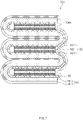
- FIG. 7 is a schematic view of an electrode assembly 10a according to another embodiment of the present invention.
- a cover material that is in a liquid state may be applied to at least a portion of the exposed surface.
- the cover part 104a may be formed by drying the cover material. Since the cover part 104a is completely in close contact with the exposed surface, it is possible to prevent not only a separator 103 but also the cover part 104a from being rolled into a sealing part during a degassing process later.
Landscapes
- Chemical & Material Sciences (AREA)
- Chemical Kinetics & Catalysis (AREA)
- Electrochemistry (AREA)
- General Chemical & Material Sciences (AREA)
- Engineering & Computer Science (AREA)
- Manufacturing & Machinery (AREA)
- Secondary Cells (AREA)
- Battery Electrode And Active Subsutance (AREA)
Abstract
Description
- The present application claims the benefit of the priority of
Korean Patent Application No. 10-2020-0033378, filed on March 18, 2020 - The present invention relates to an electrode assembly and a method for manufacturing the same, and more particularly, to an electrode assembly that is capable of preventing an electrode from being damaged, such as an occurrence of wrinkles or swells on the electrode due to a taping process or deintercalation of an active material of the electrode and a method for manufacturing the same.
- In general, secondary batteries include nickelcadmium batteries, nickel-hydrogen batteries, lithium ion batteries, and lithium ion polymer batteries. Such a secondary battery is being applied to and used in small-sized products such as digital cameras, P-DVDs, MP3Ps, mobile phones, PDAs, portable game devices, power tools, E-bikes, and the like as well as large-sized products requiring high power such as electric vehicles and hybrid vehicles, power storage devices for storing surplus power or renewable energy, and backup power storage devices.
- In order to manufacture a secondary battery, an electrode assembly is accommodated in a battery case, and an electrolyte is injected, and then, the battery case is sealed. Also, in order to manufacture the electrode assembly, first, positive electrode active material slurry is applied to a positive electrode collector, and negative electrode active material slurry is applied to a negative electrode collector to manufacture a positive electrode and a negative electrode, respectively. A separator is interposed between the positive electrode and the negative electrode to manufacture the electrode assembly. Such electrode assemblies are classified into various types. For example, the various types of electrode assemblies include a simple stack type electrode assembly, in which positive electrodes, separators, negative electrodes are simply intersected and stacked continuously without manufacturing a unit cell, a lamination & stack (L&S) type electrode assembly, in which unit cells are manufactured first using positive electrodes, separators, and negative electrodes and then are stacked, and a stack & folding (S&F) type, in which a plurality of unit cells are attached at a predetermined interval on one surface of a separator film having a long length and repetitively folded from an one end of the separator film in the same direction.
-
FIG. 1 is a perspective view of anelectrode assembly 30 according to the related art, andFIG. 2 is a front view of theelectrode assembly 30 according to the related art. - The existing simple stack type or lamination & stack
type electrode assembly 30 has a simple structure and a high degree of impregnation of an electrolyte, but has a problem in that the production speed is slow, and a degree of alignment is lowered. In order to maintain the alignment of the plurality of stacked electrodes and separators of theelectrode assembly 30, a taping process is performed. Then, as illustrated inFIG. 1 , thetape 31 is attached to each of both surfaces and portions of the top and bottom surfaces of theelectrode assembly 30. - However, in the simple stack type or lamination and stack
type electrode assembly 30, each of the negative electrode and the separator has a width that is relatively wider than that of the positive electrode. Therefore, since a peripheral portion protrudes to the outside, if thetape 31 is attached, there is a problem in that the electrode is damaged, such as an occurrence of wrinkles or swells or eintercalation of an active material of the electrode. - In addition, the
tape 31 may be detached later in an electrolyte injection process or degassing process. Particularly, since a gas within the case has to be discharged to the outside in the degassing process, there is a problem in that thetape 31 is more easily detached by a flow of the gas. - The stack & folding electrode assembly has a high production speed and high structural stability, but there is a problem in that the process is complicated, and the degree of alignment and the degree of impregnation of the electrolyte are lowered.
- (Patent Document 1)
Korea Patent Publication No. 2011-0135346 - An object of the prevent invention for solving above problems is to provide an electrode assembly that is capable of preventing an electrode from being damaged, such as an occurrence of wrinkles or swells on the electrode due to a taping process or deintercalation of an active material of the electrode and a method for manufacturing the same.
- The objects of the present invention are not limited to the aforementioned object, but other objects not described herein will be clearly understood by those skilled in the art from descriptions below.
- An electrode assembly according to an embodiment of the present invention for achieving the above object includes: a first electrode formed in the form of a single sheet and repetitively in-folded and out-folded at a predetermined interval; a second electrode provided in plurality and respectively interposed in spaces formed by folding the first electrode; a separator formed in the form of a single sheet and interposed between the first electrode and the second electrode so as to be repetitively in-folded and out-folded at a predetermined interval together with the first electrode; and a cover part configured to cover at least portions of an area, on which the separator is out-folded and an exposed surface, which is exposed to the outside together with the second electrode.
- Also, the cover part may be formed in the form of a single film.
- Also, both ends of the cover part may be attached to both ends of the first electrode, respectively.
- Also, the cover part may be in close contact with the exposed surface.
- Also, the cover part may include at least one of epoxy, polyimide, polyethylene terephthalate (PET), polypropylene (PP), or polytetrafluoroethylene (PTFE).
- Also, the first electrode may be a single-sided electrode on which a first electrode active material is applied to only one surface of a first electrode collector, and the second electrode may be a double-sided electrode on which a second electrode active material is applied to both surfaces of a second electrode collector.
- Also, the second electrode may be interposed only in each of spaces formed by in-folding the first electrode.
- Also, the separator may be interposed between one surface of the first electrode, to which the first electrode active material is applied, and the second electrode.
- Also, in the first electrode and the separator, each of areas on which one end of the second electrode may be disposed is in-folded, and each of areas on which the other end of the second electrode may be disposed is out-folded.
- Also, the cover part may cover the exposed surface through which the other end of the second electrode is exposed to the outside.
- A method for manufacturing an electrode assembly according to an embodiment of the present invention for achieving the above object includes: a step of stacking a separator formed in the form of a single sheet on one surface of a first electrode formed in the form of a single sheet in the same direction; a step of seating a plurality of second electrodes to be spaced a predetermined interval from each other on the separator so as to form an electrode stack; a step of in-folding and out-folding the first electrode and the separator to fold the electrode stack; and a step of covering at least portions of an area, on which the separator is out-folded, and an exposed surface, which is exposed to the outside together with the second electrode, through a cover part among surfaces of the electrode stack.
- Also, the step of covering the at least portions through the cover part may be performed by attaching both ends of the cover part formed in the form of a single film to both ends of the first electrode.
- Also, the step of covering the at least portions through the cover part may include: a step of applying a cover material that is in a liquid state to at least a portion of the exposed surface; and a step of drying the cover material to form the cover part.
- Also, in the step of stacking the separator, the separator may be stacked on one surface on which a first electrode active material is applied on the first electrode.
- Also, the predetermined interval may be longer than a length of the second electrode.
- Particularities of other embodiments are included in the detailed description and drawings.
- According to the embodiments of the present invention, there are at least the following effects.
- Since the first electrode is formed in the form of a single sheet, it is unnecessary to fix the electrode assembly by using the tape, and thus, the electrode may be prevented from being damaged, such as the occurrence of the wrinkles or the swells on the electrode or the deintercalation of the active material of the electrode.
- In addition, since the first electrode is the single-sided electrode, the unnecessary electrode active material may not be formed on the outermost side of the electrode assembly to improve the energy density relative to the volume.
- In addition, since it is unnecessary to manufacture the unit cell first, the continuous process may be easy, and the process time may be saved.
- In addition, since the cover part covers the area on which the separator is out-folded and the exposed surface, which is exposed to the outside together with the second electrode, the phenomenon in which the separator is rolled into the sealing part may be prevented from occurring when the degassing process is performed later.
- The effects of the prevent invention are not limited by the aforementioned description, and thus, more varied effects are involved in this specification.
-
-
FIG. 1 is a perspective view of an electrode assembly according to a related art. -
FIG. 2 is a front view of the electrode assembly according to the related art. -
FIG. 3 is a schematic view illustrating an electrode stack according to an embodiment of the present invention. -
FIG. 4 is a schematic view illustrating a shape in which the electrode stack is folded according to an embodiment of the present invention. -
FIG. 5 is a schematic view illustrating a shape in which the electrode stack is completely folded according to an embodiment of the prevent invention. -
FIG. 6 is a schematic view of an electrode assembly according to an embodiment of the present invention. -
FIG. 7 is a schematic view of an electrode assembly according to another embodiment of the present invention. - Advantages and features of the present invention, and implementation methods thereof will be clarified through following embodiments described with reference to the accompanying drawings. The present invention may, however be embodied in different forms and should not be construed as limited to the embodiments set forth herein. Rather, these embodiments are provided so that this disclosure will be thorough and complete, and will fully convey the scope of the present invention to those skilled in the art. Further, the present invention is only defined by scopes of claims. Like reference numerals refer to like elements throughout.
- Unless terms used in the present invention are defined differently, all terms (including technical and scientific terms) used herein have the same meaning as generally understood by those skilled in the art. Also, unless defined clearly and apparently in the description, the terms as defined in a commonly used dictionary are not ideally or excessively construed as having formal meaning.
- In the following description, the technical terms are used only for explaining a specific exemplary embodiment while not limiting the present invention. In this specification, the terms of a singular form may include plural forms unless specifically mentioned. The meaning of "comprises" and/or "including" does not exclude other components besides a mentioned component.
- Hereinafter, preferred embodiments will be described in detail with reference to the accompanying drawings.
-
FIG. 3 is a schematic view illustrating anelectrode stack 11 according to an embodiment of the present invention. - According to an embodiment of the present invention, since a
first electrode 101 is formed in the form of a single sheet, it is unnecessary to fix the electrode to the electrode assembly by using a tape, thereby preventing the electrode from being damaged, such as an occurrence of wrinkles or swells on the electrode or deintercalation of an active material of the electrode. In addition, since thefirst electrode 101 is the single-sided electrode, an unnecessary electrode active material may not be formed on the outermost side of theelectrode assembly 10 to improve an energy density relative to a volume. In addition, since it is unnecessary to manufacture a unit cell first, a continuous process may be easy, and a process time may be saved. In addition, since a cover part covers an area on which aseparator 103 is out-folded and an exposed surface, which is exposed to the outside together with asecond electrode 102, a phenomenon in which theseparator 103 is rolled into a sealing part may be prevented from occurring when a degassing process is performed later. - For this, a method for manufacturing the
electrode assembly 10 according to an embodiment of the present invention includes: a step of stacking theseparator 103 formed in the form of a single sheet on one surface of thefirst electrode 101 formed in the form of a single sheet in the same direction; a step of seating a plurality ofsecond electrodes 102 to be spaced a predetermined interval from each other on theseparator 103 so as to form anelectrode stack 11; a step of in-folding and out-folding thefirst electrode 101 and theseparator 103 to fold theelectrode stack 11; and a step of covering at least portions of an area, on which theseparator 103 is out-folded, and an exposed surface, which is exposed to the outside together with thesecond electrode 102, through acover part 104 among surfaces of theelectrode stack 11. - The
electrode assembly 10 manufactured through the above-described method according to an embodiment of the present invention includes afirst electrode 101 formed in the form of a single sheet and repetitively in-folded and out-folded at a predetermined interval; asecond electrode 102 provided in plurality and respectively interposed in spaces formed folding thefirst electrode 101; aseparator 103 formed in the form of a single sheet and interposed between thefirst electrode 101 and thesecond electrode 102 so as to be repetitively in-folded and out-folded at a predetermined interval together with thefirst electrode 101; and acover part 104 covering at least portions of an area, on which theseparator 103 is out-folded and an exposed surface, which is exposed to the outside together with thesecond electrode 102. - As described above, in order to manufacture the
electrode assembly 10, first, positive electrode active material slurry is applied to a positive electrode collector, and negative electrode active material slurry is applied to a negative electrode collector to manufacture a positive electrode and a negative electrode, respectively. Theseparator 103 is interposed between the positive electrode and the negative electrode, and theseparator 103 and the electrodes may be stacked to manufacture theelectrode assembly 10. - Both the electrodes of the positive and negative electrodes used in the present invention are not particularly limited, and the electrode active material may be prepared in a shape that is bonded to the electrode collector according to the typical method that is known in the art. Here, the positive electrode may be manufactured by, for example, applying slurry, in which a positive electrode active material, a conductive agent, and a binder are mixed, onto a positive electrode collector, and then drying and pressing the slurry. At this time, if necessary, the slurry may further include a filler. The positive electrode may be manufactured in the form of a sheet and mounted on a roll.
- The positive electrode collector generally has a thickness of 3 µm to 500 µm. The positive electrode collector is usually made of a material having high conductivity without causing a chemical change. Such a material may be surface-treated with, for example, stainless steel, aluminum, nickel, titanium, calcined carbon, or aluminum or stainless steel on which carbon, nickel, titanium, silver, or the like is surface-treated on a surface thereof, but is not limited thereto. Also, the positive electrode collector may form a fine unevenness on a surface thereof to increase in adhesion of the positive electrode active material. Also, the positive electrode collector may have various shapes such as a film, a sheet, a foil, a net, a porous body, a foam, a non-woven fabric, and the like.
- In a case of a lithium secondary battery, the positive electrode active material may include, for example, a layered compound of lithium cobalt oxide (LiCoO2), lithium nickel oxide (LiNiO2), etc., or a substituted compound with one or more transition metals; lithium manganese oxide such as Li1+xMn2-xO4 (x is 0 to 0.33), LiMnO3, LiMn2O3, LiMnO2, etc.; lithium copper oxide (Li2CuO2); vanadium oxide such as LiVsOs, LiFe3O4, V2O5, Cu2V2O7, etc.; Ni site-type lithium nickel oxide represented by Chemical Formula of LiNi1-xMxO2 (M=Co, Mn, Al, Cu, Fe, Mg, B or Ga, and x=0.01 to 0.3); lithium manganese complex oxide represented by Chemical Formula LiMn2-xMxO2 (M=Co, Ni, Fe, Cr, Zn or Ta, and x=0.01 to 0.1) or Li2Mn3MO8 (M=Fe, Co, Ni, Cu or Zn); LiMn2O4 in which a portion of Li is substituted with alkaline earth ions; a disulfide compound; Fe2(MoO4)3, and the like. However, this embodiment is not limited thereto.
- The conductive agent is generally added at 1 wt% to 50 wt% based on the total weight of the mixture including the positive electrode active material. The conductive agent is usually made of a material having conductivity without causing a chemical change. The conductive agent may include, for example, conductive materials such as: graphite such as natural graphite and artificial graphite; carbon black such as acetylene black, Ketjen black, furnace black, channel black, lamp black, and thermal black; conductive fiber such as carbon fiber and metal fiber; metal powder such as carbon fluorine, aluminum, and nickel powder; conductive whisker such as zinc oxide and potassium titanate; conductive oxide such as titanium oxide; or polyphenylene derivatives.
- The binder is a component assisting the bonding of the active material to the conductive agent and the bonding to the collector and is commonly added at 1 wt% to 50 wt% based on the total weight of the mixture including the positive electrode active material. Examples of the binder may include polyfluoro vinylidene, polyvinyl alcohol, carboxymethyl cellulose (CMC), starch, hydroxypropyl cellulose, regenerated cellulose, polyvinyl pyrrolidone, tetrafluoroethylene, polyethylene, polypropylene, ethylenepropylene-diene polymer (EPDM), sulfonated EPDM, styrene butadiene rubber, fluorine rubber, various copolymers, and the like.
- The filler is optionally used as a component that inhibits expansion of the positive electrode. Also, a general filler may be used if the filler is a fibrous material without causing the chemical change. Examples of the filler may include olefin polymers such as polyethylene and polypropylene; and fibrous materials such as glass fibers and carbon fibers.
- The negative electrode may be manufactured by, for example, applying the negative electrode active material onto the negative electrode collector and then drying and pressing the negative electrode active material. If necessary, the negative electrode active material may optionally include the conductive agent, the binder, the filler, and the like. The negative electrode may be manufactured in the form of a sheet and mounted on a roll.
- The negative electrode collector generally has a thickness of 3 µm to 500 µm. The negative electrode collector is usually made of a material having conductivity without causing a chemical change. Examples of the material include copper, stainless steel, aluminum, nickel, titanium, calcined carbon, copper or stainless steel on which carbon, nickel, titanium, silver, or the like is surface-treated on a surface thereof, or aluminum-cadmium alloys. Also, the negative electrode collector may form a fine unevenness on the surface thereof to increase in bonding force of the negative electrode active material. Also, the negative electrode collector may have various shapes such as a film, a sheet, a foil, a net, a porous body, a foam, or a non-woven fabric.
- The negative electrode active material may include, for example, carbon such as non-graphitized carbon, graphite-based carbon, etc.; a metal complex oxide such as LixFe2O3 (0 ≤x≤1), LixWO2 (0≤x≤1), SnxMe1-xMe'yOz (Me: Mn, Fe, Pb, Ge; Me': Al, B, P, Si, elements found in Group 1, Group 2 and Group 3 in a periodic table, halogen; 0<x≤1; 1≤y≤3; 1≤z≤ 8), etc.; a lithium metal; a lithium alloy; a silicon-based alloy; a tin-based alloy; a metal oxide such as SnO, SnO2, PbO, PbO2, Pb2O3, Pb3O4, Sb2O3, Sb2O4, Sb2O5, GeO, GeO2, Bi2O3, Bi2O4, Bi2O5, etc.; a conductive polymer such as polyacetylene, etc.; Li-Co-Ni-based material, and the like.
- A commonly known polyolefin-based
separator 103 or acomposite separator 103 in which an organic and inorganic composite layer is formed on the olefin-based material may be used as theseparator 103, which is disposed between the positive electrode and the negative electrode to insulate the electrodes from each other, but is not particularly limited. - The
electrode assembly 10 having the above structure is accommodated in a battery case. Then, an electrolyte is injected, and the battery case is sealed to manufacture a secondary battery. - According to an embodiment of the present invention, the
first electrode 101 may be a positive electrode, and thesecond electrode 102 may be a negative electrode, but are not limited thereto. For example, thefirst electrode 101 may be a negative electrode, and thesecond electrode 102 may be a positive electrode. - First, as illustrated in
FIG. 3 , oneseparator 103 formed in the form of a single sheet is stacked on one surface of thefirst electrode 101 formed in the form of a single sheet in the same direction. Here, thefirst electrode 101 is a single-sided electrode in which a first electrodeactive material 1012 is applied to only one surface of afirst electrode collector 1011. Thus, the first electrodeactive material 1012 is formed on one surface of thefirst electrode 101, and the first electrodeactive material 1012 is not formed on the other surface of thefirst electrode 101. As a result, thefirst electrode collector 1011 is exposed to the outside. Theseparator 103 formed in the form of a single sheet is preferably stacked on one surface of thefirst electrode 101 to which the first electrodeactive material 1012 is applied. - Then, the plurality of
second electrodes 102 are seated to be spaced a predetermined interval from each other on theseparator 103 to form anelectrode stack 11. Here, thesecond electrode 102 is a double-sided electrode in which the second electrodeactive material 1022 is applied to all both surfaces of thesecond electrode collector 1021. Thus, the second electrodeactive material 1022 is formed on both one side and the other side of thesecond electrode 102. - It is preferable that the predetermined interval is longer than a length of the
second electrode 102. If the predetermined interval is shorter than the length of thesecond electrode 102, when theelectrode stack 11 is folded later, thesecond electrode 102 is not evenly aligned and thus protrudes outward. However, if the predetermined interval is longer than the length of thesecond electrode 102, thesecond electrode 102 is evenly aligned to reduce a volume, and an area on which thesecond electrode 102 and thefirst electrode 101 overlap each other increase to increase in energy density. -
FIG. 4 is a schematic view illustrating a shape in which theelectrode stack 11 is folded according to an embodiment of the present invention, andFIG. 5 is a schematic view illustrating a shape in which theelectrode stack 11 is completely folded according to an embodiment of the prevent invention. - As illustrated in
FIG. 4 , theelectrode stack 11 is folded by in-folding and out-folding thefirst electrode 101 and theseparator 103. That is, in theelectrode stack 11, the sheet on which thefirst electrode 101 and theseparator 103 are stacked is in-folded at one side and then out-folded in an opposite direction, and then, this process is alternately and repetitively performed. Also, the sheet is continuously folded from one side to the other side thereof. At this time, in thefirst electrode 101 and theseparator 103, each of areas I.A on which one end of thesecond electrode 102 is disposed may be in-folded, and each of areas O.A on which theother end 1024 of thesecond electrode 102 may be out-folded. That is, the in-folding areas and the out-folding areas in thefirst electrode 101 and theseparator 103 may be determined according to a position of thesecond electrode 102. - Herein, the in-folding refers to folding in a direction in which the
first electrode 101 surrounds thesecond electrode 102. Thus, when the in-folding is performed, theseparator 103 and thefirst electrode 101 are sequentially stacked on both the surfaces of thesecond electrode 102. Also, the out-folding refers to folding in a direction in which thefirst electrode 101 excludes thesecond electrode 102 as the contrary concept of the in-folding. Thus, when the out-folding is performed, thefirst electrode collectors 1011, which are exposed through the other surface of thefirst electrode 101, are stacked on each other. As illustrated inFIG. 5 , theelectrode stack 11 may be completely folded in the same manner as described above. -
FIG. 6 is a schematic view of theelectrode assembly 10 according to an embodiment of the present invention. - As illustrated in
FIG. 6 , among a plurality of surfaces constituting the completely foldedelectrode stack 11, at least portions of an area O.A on which theseparator 103 is out-folded and an exposed surface, which is exposed to the outside together with thesecond electrode 102 may be covered by thecover part 104. Thecover part 104 may be formed in the form of a single film. Also, both ends of thecover part 104 may be attached to both ends of thefirst electrode 101 to cover the exposed surface. Thus, theelectrode assembly 10 according to an embodiment of the present invention may be manufactured. - The
electrode assembly 10 includes thefirst electrode 101, thesecond electrode 102, theseparator 103, and thecover part 104. - The
first electrode 101 is a single-sided electrode on which the first electrodeactive material 1012 is applied to only one surface of thefirst electrode collector 1011, is formed in the form of a single sheet, and repetitively in-folded and out-folded at a predetermined interval. - The
second electrode 102 is a double-sided electrode on which the second electrodeactive material 1022 is applied to both the surfaces of thesecond electrode collector 1021, is provided in plurality, and is interposed in a space formed by folding thefirst electrode 101. Particularly, it is preferable that thesecond electrode 102 be interposed only in a space formed by in-folding thefirst electrode 101. - The
separator 103 is formed in the form of a single sheet, is interposed between thefirst electrode 101 and thesecond electrode 102, and repetitively in-folded and out-folded at a predetermined interval together with thefirst electrode 101. Particularly, theseparator 103 is interposed between one surface of thefirst electrode 102, to which the first electrodeactive material 1012 is applied, and thesecond electrode 102. - In general, both the outermost surfaces of the
electrode assembly 10 are not used to generate electricity. However, in theelectrode assembly 10 according to an embodiment of the present invention, as illustrated inFIG. 6 , thefirst electrode collector 1011 of thefirst electrode 101, which is the single-sided electrode, is exposed on both the outermost surfaces. Thus, since the first electrodeactive material 1012 is not formed on both the outermost surfaces that do not generate electricity, the energy density may increase. - However, according to an embodiment of the present invention, since the electrode collectors are also staked on each other at the out-folded portion of the
first electrode 101, the out-folded portion is not used to generate electricity. However, in general, the electrode active material is much thicker than the electrode collector in the electrode. Thus, even if the out-folded portion of thefirst electrode 101 does not generate electricity, the thickness is much thinner to reduce the volume. That is, the energy density relative to the volume may be further improved. - In addition, since the
first electrode 101 and theseparator 103 are formed in the form of a single sheet, it is unnecessary to fix the electrode to the electrode assembly by using a tape, thereby preventing the electrode from being damaged, such as an occurrence of wrinkles or swells on the electrode or deintercalation of the active material of the electrode. In addition, since it is unnecessary to manufacture a unit cell first, a continuous process may be easy, and a process time may be saved. - In the
first electrode 101 and theseparator 103, each of the areas I.A on which one end of thesecond electrode 102 is disposed is in-folded, and each of the areas O.A on which theother end 1024 of thesecond electrode 102 is out-folded. Thus, the areas O.A on which theseparator 103 is out-folded and theother end 1024 of thesecond electrode 102 are exposed to the outside. - Among the plurality of surfaces constituting the completely folded
electrode stack 11, the areas OA on which theseparator 103 is out-folded and theother end 1024 of thesecond electrode 102 are provided in plurality on the exposed surface and thus are disposed alternately to be exposed together to the outside. Furthermore, as illustrated inFIG. 5 , one end or both ends of theseparator 103 may also be exposed to the outside through the exposed surface according to the number of times of stacking of theelectrode stack 11. Also, the exposed portions of theseparator 103 may be detached from each other or damaged due to an external impact. For example, theelectrode assembly 10 may be accommodated in a pouch-type battery case and may undergo an activation process, and then a degassing process may be performed. At this time, theelectrode assembly 10 inside the battery case may move in a direction in which theelectrode assembly 10 is degassed by the degassing process. If the degassing process is completed in this state, and the sealing part is completely sealed, a phenomenon, in which the exposedseparator 103 is rolled into the sealing part, may occur. Here, one end or both ends of theseparator 103 may be rolled in, and the area O.A on which theseparator 103 is out-folded may be rolled in. Also, due to such a damage, a defect in insulation between thefirst electrode 101 and thesecond electrode 102 may occur. - The
cover part 104 covers at least a portion of the exposed surface. In particular, in order to prevent theseparator 103 and the electrode from being damaged, it is preferable to cover the entire exposed surface. Here, thecover part 104 may be formed in the form of a single film. Also, both ends of thecover part 104 may be attached to both ends of thefirst electrode 101 to cover the exposed surface. As a result, it is possible to prevent the phenomenon, in which theseparator 103 is rolled into the sealing part during the degassing process later, from occurring. However, the present invention is not limited thereto, and thecover part 104 has a shape constituted by a plurality of films and may be attached to be spaced apart from each other on the exposed surface of theelectrode stack 11 in a longitudinal length direction of theelectrode stack 11. Here, as the spaced interval is narrowed, the phenomenon, in which theseparator 103 is rolled into the sealing part, may be reliably prevented from occurring. - As illustrated in
FIG. 6 , it is preferable that the attachment area of both the ends of thecover part 104 is wide, and it is more preferable to be attached to both the entire outermost surfaces of theelectrode assembly 10. Therefore, even if thecover part 104 is in contact with the electrolyte inside the battery case, thecover part 104 may not be detached from thefirst electrode 101. - The
cover part 104 may include at least one of insulating materials such as epoxy, polyimide, polyethylene terephthalate (PET), polypropylene (PP), and polytetrafluoroethylene (PTFE). Thus, even if the electrode is damaged, defective insulation between thefirst electrode 101 and thesecond electrode 102 may be prevented. -
FIG. 7 is a schematic view of anelectrode assembly 10a according to another embodiment of the present invention. - According to another embodiment of the present invention, when at least a portion of an exposed surface is covered with a
cover part 104a, a cover material that is in a liquid state may be applied to at least a portion of the exposed surface. In addition, thecover part 104a may be formed by drying the cover material. Since thecover part 104a is completely in close contact with the exposed surface, it is possible to prevent not only aseparator 103 but also thecover part 104a from being rolled into a sealing part during a degassing process later. - Those with ordinary skill in the technical field of the present invention pertains will be understood that the present invention can be carried out in other specific forms without changing the technical idea or essential features. Therefore, the above-disclosed embodiments are to be considered illustrative and not restrictive. Accordingly, the scope of the present invention is defined by the appended claims rather than the foregoing description and the exemplary embodiments described therein. Various modifications made within the meaning of an equivalent of the claims of the invention and within the claims are to be regarded to be in the scope of the present invention.
-
- 10, 30: Electrode assembly 11: Electrode stack
- 101: First electrode 1011: First electrode collector
- 1012: First electrode active material 102: Second electrode
- 1021: Second electrode collector 1022: Second electrode active material
- 1023: One end of second electrode 1024: The other end of second electrode
- 103: Separator 104: Cover part
- 31: Tape
Claims (15)
- An electrode assembly comprising:a first electrode formed in the form of a single sheet and repetitively in-folded and out-folded at a predetermined interval;a second electrode provided in plurality and respectively interposed in spaces formed by folding the first electrode;a separator formed in the form of a single sheet and interposed between the first electrode and the second electrode so as to be repetitively in-folded and out-folded at a predetermined interval together with the first electrode; anda cover part configured to cover at least portions of an area, on which the separator is out-folded and an exposed surface, which is exposed to the outside together with the second electrode.
- The electrode assembly of claim 1, wherein the cover part is formed in the form of a single film.
- The electrode assembly of claim 2, wherein both ends of the cover part are attached to both ends of the first electrode, respectively.
- The electrode assembly of claim 1, wherein the cover part is in close contact with the exposed surface.
- The electrode assembly of claim 1, wherein the cover part comprises at least one of epoxy, polyimide, polyethylene terephthalate (PET), polypropylene (PP), or polytetrafluoroethylene (PTFE).
- The electrode assembly of claim 1, wherein the first electrode is a single-sided electrode on which a first electrode active material is applied to only one surface of a first electrode collector, and
the second electrode is a double-sided electrode on which a second electrode active material is applied to both surfaces of a second electrode collector. - The electrode assembly of claim 6, wherein the second electrode is interposed only in each of spaces formed by in-folding the first electrode.
- The electrode assembly of claim 6, wherein the separator is interposed between one surface of the first electrode, to which the first electrode active material is applied, and the second electrode.
- The electrode assembly of claim 1, wherein, in the first electrode and the separator, each of areas on which one end of the second electrode is disposed is in-folded, and
each of areas on which the other end of the second electrode is disposed is out-folded. - The electrode assembly of claim 9, wherein the cover part covers the exposed surface through which the other end of the second electrode is exposed to the outside.
- A method for manufacturing an electrode assembly, the method comprising:a step of stacking a separator formed in the form of a single sheet on one surface of a first electrode formed in the form of a single sheet in the same direction;a step of seating a plurality of second electrodes to be spaced a predetermined interval from each other on the separator so as to form an electrode stack;a step of in-folding and out-folding the first electrode and the separator to fold the electrode stack; anda step of covering at least portions of an area, on which the separator is out-folded, and an exposed surface, which is exposed to the outside together with the second electrode, through a cover part among surfaces of the electrode stack.
- The method of claim 11, wherein the step of covering the at least portions through the cover part is performed by attaching both ends of the cover part formed in the form of a single film to both ends of the first electrode.
- The method of claim 11, wherein the step of covering the at least portions through the cover part comprises:a step of applying a cover material that is in a liquid state to at least a portion of the exposed surface; anda step of drying the cover material to form the cover part.
- The method of claim 11, wherein, in the step of stacking the separator, the separator is stacked on one surface on which a first electrode active material is applied on the first electrode.
- The method of claim 11, wherein the predetermined interval is longer than a length of the second electrode.
Applications Claiming Priority (2)
| Application Number | Priority Date | Filing Date | Title |
|---|---|---|---|
| KR1020200033378A KR102838321B1 (en) | 2020-03-18 | 2020-03-18 | The Electrode Assembly And The Method For Manufacturing Thereof |
| PCT/KR2020/018765 WO2021187726A1 (en) | 2020-03-18 | 2020-12-21 | Electrode assembly and method for manufacturing same |
Publications (2)
| Publication Number | Publication Date |
|---|---|
| EP4053953A1 true EP4053953A1 (en) | 2022-09-07 |
| EP4053953A4 EP4053953A4 (en) | 2024-05-29 |
Family
ID=77771302
Family Applications (1)
| Application Number | Title | Priority Date | Filing Date |
|---|---|---|---|
| EP20925047.1A Pending EP4053953A4 (en) | 2020-03-18 | 2020-12-21 | ELECTRODE ASSEMBLY AND METHOD FOR MANUFACTURING SAME |
Country Status (5)
| Country | Link |
|---|---|
| US (1) | US12542298B2 (en) |
| EP (1) | EP4053953A4 (en) |
| KR (1) | KR102838321B1 (en) |
| CN (1) | CN114730906A (en) |
| WO (1) | WO2021187726A1 (en) |
Families Citing this family (4)
| Publication number | Priority date | Publication date | Assignee | Title |
|---|---|---|---|---|
| KR102622632B1 (en) * | 2021-10-07 | 2024-01-09 | 주식회사 엘지에너지솔루션 | Electrode assembly and battery cell including same |
| US20240283003A1 (en) * | 2021-10-07 | 2024-08-22 | Lg Energy Solution, Ltd. | Electrode Assembly and Battery Cell Including the Same |
| CN116783746A (en) * | 2021-11-23 | 2023-09-19 | 宁德时代新能源科技股份有限公司 | Electrode components, battery cells, batteries and electrical devices |
| US20250372722A1 (en) * | 2022-10-21 | 2025-12-04 | Lg Energy Solution, Ltd. | Electrode assembly and electrochemical device including same |
Family Cites Families (33)
| Publication number | Priority date | Publication date | Assignee | Title |
|---|---|---|---|---|
| JP3338071B2 (en) * | 1991-10-11 | 2002-10-28 | 旭化成株式会社 | Battery |
| US5300373A (en) | 1992-09-11 | 1994-04-05 | Valence Technology, Inc. | Electrochemical cell stack and method of making an electrochemical cell stack |
| US5958088A (en) | 1998-03-04 | 1999-09-28 | Duracell, Inc. | Prismatic cell construction |
| TW439309B (en) * | 1999-01-22 | 2001-06-07 | Toshiba Corp | Nonaquous electrolyte secondary battery |
| JP2004207119A (en) * | 2002-12-26 | 2004-07-22 | Mitsubishi Materials Corp | Lithium-ion polymer secondary battery |
| JP2005190912A (en) * | 2003-12-26 | 2005-07-14 | Matsushita Electric Ind Co Ltd | Lithium secondary battery and manufacturing method thereof |
| US20050175902A1 (en) * | 2004-02-11 | 2005-08-11 | Mohammad Parsian | Lithium polymer battery cell |
| KR100853619B1 (en) | 2006-01-04 | 2008-08-25 | 주식회사 엘지화학 | Electrode assembly is sealed the top of the separator and a secondary battery comprising the same |
| JP2007273320A (en) | 2006-03-31 | 2007-10-18 | Sanyo Electric Co Ltd | Lithium secondary battery |
| KR101243435B1 (en) | 2006-05-08 | 2013-03-13 | 삼성에스디아이 주식회사 | Secondary battery |
| JP2010067443A (en) | 2008-09-10 | 2010-03-25 | Sumitomo Electric Ind Ltd | Battery and manufacturing method therefor |
| JP5259453B2 (en) * | 2009-02-25 | 2013-08-07 | 富士重工業株式会社 | Electric storage device and manufacturing method thereof |
| JP5115591B2 (en) | 2010-06-10 | 2013-01-09 | 株式会社デンソー | Battery electrode stack |
| JP2012156405A (en) | 2011-01-27 | 2012-08-16 | Fdk Corp | Electricity storage device |
| KR101446160B1 (en) | 2012-12-07 | 2014-10-01 | 주식회사 엘지화학 | Electrode assembly with tape and Electrochemical device comprising the same |
| US9246185B2 (en) * | 2013-03-14 | 2016-01-26 | Sion Power Corporation | Electrochemical cell having a folded electrode and separator, battery including the same, and method of forming same |
| US20140272559A1 (en) * | 2013-03-14 | 2014-09-18 | Robert Bosch Gmbh | Electrochemical cell including a folded electrode, components thereof, battery including the electrochemical cell, and method of forming same |
| DE102013019071A1 (en) * | 2013-11-15 | 2015-05-21 | Karlsruher Institut für Technologie | Electrode assembly, process for its preparation and electrochemical cell |
| KR102207921B1 (en) | 2013-11-18 | 2021-01-27 | 삼성전자주식회사 | Metal-air battery having folded structure and method of fabricating the same |
| KR20160024089A (en) | 2014-08-22 | 2016-03-04 | 에스케이이노베이션 주식회사 | Separator of lithium polymer secondary battery and lithium polymer secondary battery |
| JP6406040B2 (en) | 2015-01-30 | 2018-10-17 | 株式会社豊田自動織機 | Electrode assembly and battery cell |
| KR101775565B1 (en) * | 2015-02-13 | 2017-09-19 | 주식회사 엘지화학 | Electrode Assembly Comprising Single Anode Sheet |
| JP6583711B2 (en) | 2015-03-17 | 2019-10-02 | 株式会社Gsユアサ | Electricity storage element |
| KR102288544B1 (en) * | 2015-06-29 | 2021-08-11 | 삼성에스디아이 주식회사 | Secondary Battery And Fabricating Method Thereof |
| KR102023530B1 (en) | 2015-08-12 | 2019-09-24 | 주식회사 엘지화학 | Electrode assembly |
| JP6615660B2 (en) * | 2016-03-17 | 2019-12-04 | 株式会社東芝 | Non-aqueous electrolyte battery, battery pack and vehicle |
| KR102229624B1 (en) * | 2016-09-21 | 2021-03-17 | 삼성에스디아이 주식회사 | Rechageable battery |
| KR102155707B1 (en) | 2016-11-04 | 2020-09-14 | 주식회사 엘지화학 | Electrode assembly and the manufacturing method |
| JP2019046624A (en) | 2017-08-31 | 2019-03-22 | 株式会社豊田自動織機 | Tape adhesion method of electrode assembly |
| JP6975400B2 (en) | 2017-09-12 | 2021-12-01 | 株式会社Gsユアサ | Power storage element |
| KR102555500B1 (en) | 2017-12-18 | 2023-07-12 | 삼성에스디아이 주식회사 | Electrode assembly |
| KR20190079961A (en) | 2017-12-28 | 2019-07-08 | 주식회사 엘지화학 | Method for manufacturing electrode assembly and electrode assembly manufactured thereby |
| JP2020013705A (en) * | 2018-07-18 | 2020-01-23 | 積水化学工業株式会社 | Stacked battery |
-
2020
- 2020-03-18 KR KR1020200033378A patent/KR102838321B1/en active Active
- 2020-12-21 CN CN202080079383.XA patent/CN114730906A/en active Pending
- 2020-12-21 US US17/783,484 patent/US12542298B2/en active Active
- 2020-12-21 EP EP20925047.1A patent/EP4053953A4/en active Pending
- 2020-12-21 WO PCT/KR2020/018765 patent/WO2021187726A1/en not_active Ceased
Also Published As
| Publication number | Publication date |
|---|---|
| EP4053953A4 (en) | 2024-05-29 |
| US20230010746A1 (en) | 2023-01-12 |
| CN114730906A (en) | 2022-07-08 |
| KR102838321B1 (en) | 2025-07-24 |
| KR20210117045A (en) | 2021-09-28 |
| US12542298B2 (en) | 2026-02-03 |
| WO2021187726A1 (en) | 2021-09-23 |
Similar Documents
| Publication | Publication Date | Title |
|---|---|---|
| EP2555305B1 (en) | Electrode assembly having a novel structure and a production method for the same | |
| KR102234993B1 (en) | Battery Cell and Manufacturing Method thereof | |
| US10547090B2 (en) | Battery cell including electrode lead containing gas adsorbent | |
| US12542298B2 (en) | Electrode assembly and method for manufacturing the same | |
| EP4064396B1 (en) | Electrode and electrode assembly | |
| CN111527627A (en) | Method for manufacturing negative electrode and negative electrode obtained therefrom | |
| US11870039B2 (en) | Electrode assembly and method for manufacturing the same | |
| EP2899769B1 (en) | Pouch for secondary battery and secondary battery comprising same | |
| KR20130133328A (en) | Secondary battery of improved safety | |
| KR102872092B1 (en) | Method for manufacturing an electrode having a resistance layer | |
| EP4044331A1 (en) | Pouch-type secondary battery having increased energy density, and method for manufacturing same | |
| KR101484369B1 (en) | Secondary battery and electrochemical cell having the same | |
| KR102836399B1 (en) | Activation method of lithium secondary battery | |
| KR20240033576A (en) | Jelly roll type battery cell | |
| KR20140018136A (en) | Electrode assembly and electrochemical cell containing the same | |
| US20260018681A1 (en) | Electrode assembly and lithium secondary battery including the same | |
| KR102826850B1 (en) | Pouch type Secondary Battery | |
| EP4672418A1 (en) | ELECTRODE ARRANGEMENT AND LITHIUM SECONDARY BATTERY SO THAT | |
| CA3286193A1 (en) | Electrode assembly and lithium secondary battery including the same | |
| KR20260050099A (en) | Battery cell | |
| KR20250094438A (en) | Electrode assembly and lithium secondary battery comprising the same | |
| KR20160068426A (en) | Lithium secondary battery | |
| KR20170059787A (en) | Folding type Electrode assembly and method for fabricating the same |
Legal Events
| Date | Code | Title | Description |
|---|---|---|---|
| STAA | Information on the status of an ep patent application or granted ep patent |
Free format text: STATUS: THE INTERNATIONAL PUBLICATION HAS BEEN MADE |
|
| PUAI | Public reference made under article 153(3) epc to a published international application that has entered the european phase |
Free format text: ORIGINAL CODE: 0009012 |
|
| STAA | Information on the status of an ep patent application or granted ep patent |
Free format text: STATUS: REQUEST FOR EXAMINATION WAS MADE |
|
| 17P | Request for examination filed |
Effective date: 20220531 |
|
| AK | Designated contracting states |
Kind code of ref document: A1 Designated state(s): AL AT BE BG CH CY CZ DE DK EE ES FI FR GB GR HR HU IE IS IT LI LT LU LV MC MK MT NL NO PL PT RO RS SE SI SK SM TR |
|
| DAV | Request for validation of the european patent (deleted) | ||
| DAX | Request for extension of the european patent (deleted) | ||
| A4 | Supplementary search report drawn up and despatched |
Effective date: 20240502 |
|
| RIC1 | Information provided on ipc code assigned before grant |
Ipc: H01M 10/0583 20100101ALN20240426BHEP Ipc: H01M 10/052 20100101ALN20240426BHEP Ipc: H01M 10/04 20060101AFI20240426BHEP |
|
| STAA | Information on the status of an ep patent application or granted ep patent |
Free format text: STATUS: EXAMINATION IS IN PROGRESS |
|
| 17Q | First examination report despatched |
Effective date: 20241210 |