EP4053629A1 - Camera device - Google Patents
Camera device Download PDFInfo
- Publication number
- EP4053629A1 EP4053629A1 EP22158632.4A EP22158632A EP4053629A1 EP 4053629 A1 EP4053629 A1 EP 4053629A1 EP 22158632 A EP22158632 A EP 22158632A EP 4053629 A1 EP4053629 A1 EP 4053629A1
- Authority
- EP
- European Patent Office
- Prior art keywords
- power transmission
- rotation
- transmission member
- camera
- angle range
- Prior art date
- Legal status (The legal status is an assumption and is not a legal conclusion. Google has not performed a legal analysis and makes no representation as to the accuracy of the status listed.)
- Granted
Links
Images



Classifications
-
- G—PHYSICS
- G03—PHOTOGRAPHY; CINEMATOGRAPHY; ANALOGOUS TECHNIQUES USING WAVES OTHER THAN OPTICAL WAVES; ELECTROGRAPHY; HOLOGRAPHY
- G03B—APPARATUS OR ARRANGEMENTS FOR TAKING PHOTOGRAPHS OR FOR PROJECTING OR VIEWING THEM; APPARATUS OR ARRANGEMENTS EMPLOYING ANALOGOUS TECHNIQUES USING WAVES OTHER THAN OPTICAL WAVES; ACCESSORIES THEREFOR
- G03B11/00—Filters or other obturators specially adapted for photographic purposes
- G03B11/04—Hoods or caps for eliminating unwanted light from lenses, viewfinders or focusing aids
- G03B11/043—Protective lens closures or lens caps built into cameras
-
- G—PHYSICS
- G03—PHOTOGRAPHY; CINEMATOGRAPHY; ANALOGOUS TECHNIQUES USING WAVES OTHER THAN OPTICAL WAVES; ELECTROGRAPHY; HOLOGRAPHY
- G03B—APPARATUS OR ARRANGEMENTS FOR TAKING PHOTOGRAPHS OR FOR PROJECTING OR VIEWING THEM; APPARATUS OR ARRANGEMENTS EMPLOYING ANALOGOUS TECHNIQUES USING WAVES OTHER THAN OPTICAL WAVES; ACCESSORIES THEREFOR
- G03B11/00—Filters or other obturators specially adapted for photographic purposes
- G03B11/04—Hoods or caps for eliminating unwanted light from lenses, viewfinders or focusing aids
- G03B11/045—Lens hoods or shields
-
- G—PHYSICS
- G03—PHOTOGRAPHY; CINEMATOGRAPHY; ANALOGOUS TECHNIQUES USING WAVES OTHER THAN OPTICAL WAVES; ELECTROGRAPHY; HOLOGRAPHY
- G03B—APPARATUS OR ARRANGEMENTS FOR TAKING PHOTOGRAPHS OR FOR PROJECTING OR VIEWING THEM; APPARATUS OR ARRANGEMENTS EMPLOYING ANALOGOUS TECHNIQUES USING WAVES OTHER THAN OPTICAL WAVES; ACCESSORIES THEREFOR
- G03B17/00—Details of cameras or camera bodies; Accessories therefor
- G03B17/02—Bodies
-
- G—PHYSICS
- G03—PHOTOGRAPHY; CINEMATOGRAPHY; ANALOGOUS TECHNIQUES USING WAVES OTHER THAN OPTICAL WAVES; ELECTROGRAPHY; HOLOGRAPHY
- G03B—APPARATUS OR ARRANGEMENTS FOR TAKING PHOTOGRAPHS OR FOR PROJECTING OR VIEWING THEM; APPARATUS OR ARRANGEMENTS EMPLOYING ANALOGOUS TECHNIQUES USING WAVES OTHER THAN OPTICAL WAVES; ACCESSORIES THEREFOR
- G03B17/00—Details of cameras or camera bodies; Accessories therefor
- G03B17/56—Accessories
- G03B17/561—Support related camera accessories
-
- G—PHYSICS
- G03—PHOTOGRAPHY; CINEMATOGRAPHY; ANALOGOUS TECHNIQUES USING WAVES OTHER THAN OPTICAL WAVES; ELECTROGRAPHY; HOLOGRAPHY
- G03B—APPARATUS OR ARRANGEMENTS FOR TAKING PHOTOGRAPHS OR FOR PROJECTING OR VIEWING THEM; APPARATUS OR ARRANGEMENTS EMPLOYING ANALOGOUS TECHNIQUES USING WAVES OTHER THAN OPTICAL WAVES; ACCESSORIES THEREFOR
- G03B7/00—Control of exposure by setting shutters, diaphragms or filters, separately or conjointly
- G03B7/26—Power supplies; Circuitry or arrangement to switch on the power source; Circuitry to check the power source voltage
-
- G—PHYSICS
- G08—SIGNALLING
- G08B—SIGNALLING SYSTEMS, e.g. PERSONAL CALLING SYSTEMS; ORDER TELEGRAPHS; ALARM SYSTEMS
- G08B13/00—Burglar, theft or intruder alarms
- G08B13/18—Actuation by interference with heat, light, or radiation of shorter wavelength; Actuation by intruding sources of heat, light, or radiation of shorter wavelength
- G08B13/189—Actuation by interference with heat, light, or radiation of shorter wavelength; Actuation by intruding sources of heat, light, or radiation of shorter wavelength using passive radiation detection systems
- G08B13/194—Actuation by interference with heat, light, or radiation of shorter wavelength; Actuation by intruding sources of heat, light, or radiation of shorter wavelength using passive radiation detection systems using image scanning and comparing systems
- G08B13/196—Actuation by interference with heat, light, or radiation of shorter wavelength; Actuation by intruding sources of heat, light, or radiation of shorter wavelength using passive radiation detection systems using image scanning and comparing systems using television cameras
- G08B13/19617—Surveillance camera constructional details
- G08B13/1963—Arrangements allowing camera rotation to change view, e.g. pivoting camera, pan-tilt and zoom [PTZ]
Definitions
- the present invention relates to a camera device.
- Patent Document 1 discloses a camera device (surveillance camera device) that changes the facing direction of a camera by using the driving force of a motor (actuator).
- the camera device of Patent Document 1 also includes a mechanism that moves the camera in an optical axis direction of the camera in conjunction with an operation that changes the facing direction of the camera. That is to say, the camera device of Patent Document 1 is configured to move a camera (a single object) in two directions (a direction that changes the facing direction of the camera, and the optical axis direction) at the same time.
- a shutter that covers the camera to prevent unnecessary capture by the camera for the purpose of protecting privacy.
- a shutter may be provided so as to be movable between a position that covers the camera and a position that does not cover the camera.
- the shutter may be moved manually, for example, this is inconvenient if the camera device is installed in a place that is out of reach, or in a place that is hard to reach. Therefore, it is conceivable to move the shutter by using the driving force of a motor.
- An example object of the present invention is to provide a camera device which is capable of independently moving a camera and a shutter with the drive force of the same motor, while also reducing the number of components and simplifying the structure.
- a camera device includes: a base member; a camera which is rotatably attached to the base member about a first rotation axis; a shutter member which is rotatably attached to the base member about a second rotation axis, the second rotation axis being different from the first rotation axis and being parallel to the first rotation axis, the shutter member being capable of rotating between a cover position in which the shutter member covers the camera, and an open position in which the shutter member does not cover the camera; a power transmission member which is rotatably attached to the base member about a third rotation axis, the third rotation axis being different from the first rotation axis and being parallel to the first rotation axis; and a motor configured to rotationally drive the power transmission member.
- the power transmission member causes the camera to rotate together with a rotation of the power transmission member in a first rotation angle range of the power transmission member.
- the power transmission member causes the shutter member to rotate together with a rotation of the power transmission member in a second rotation angle range of the power transmission member, the second rotation angle range being different from the first rotation angle range.
- a camera device 1 includes a base member 2, a camera 3, a shutter member 4, a power transmission member 5, and a motor 6.
- the camera device 1 of the present embodiment further includes a reduction gear mechanism 7.
- the base member 2 is configured so as to attach together the camera 3, the shutter member 4, the power transmission member 5, the motor 6, and the reduction gear mechanism 7.
- the base member 2 of the present embodiment is configured as a case that accommodates the camera 3, the power transmission member 5, the motor 6, and the reduction gear mechanism 7.
- the base member 2 includes a base body 21 and a side wall portion 22. In FIG. 4 , the side wall portion 22 is omitted.
- the camera 3, the power transmission member 5, the motor 6, and the reduction gear mechanism 7 are mainly attached to the base body 21.
- the base body 21 is formed with an opening portion (opening) 21A that allows the camera 3 accommodated inside the base body 21 to face the outside.
- the direction in which the opening portion 21A of the base body 21 faces may be referred to as the front, and the direction opposite to the front (negative X-axis direction) may be referred to as the rear.
- a first direction (Y-axis direction) orthogonal to the front-rear direction (X-axis direction) may be referred to as the width direction.
- a second direction (Z-axis direction) orthogonal to the front-rear direction may be referred to as the up-down direction.
- the positive Z-axis direction in the drawings may be referred to as up
- the negative Z-axis direction may be referred to as down.
- the side wall portion 22 is attached to one side of the base body 21 in the width direction (positive Y-axis direction side), and covers the camera 3, a portion of the shutter member 4 (a portion of a first side plate portion 43A described below), the power transmission member 5, the motor 6, and the reduction gear mechanism 7 attached to the base body 21.
- the camera 3 shown in FIG. 1 to 5 captures images and videos.
- the camera 3 is rotatably attached to the base member 2 about a first rotation axis A1.
- the camera 3 has a first locking groove 31 formed so as to extend in the radial direction of the first rotation axis A1.
- the camera 3 of the present embodiment will be described in detail.
- the camera 3 of the present embodiment has a cylindrical portion 32 whose interior is provided with a photography lens (not shown).
- the optical axis OA of the camera 3 coincides with the central axis of the cylindrical portion 32.
- the optical axis OA may, for example, be positioned with an offset with respect to the central axis of the cylindrical portion 32.
- the camera 3 is disposed at the position of the base member 2 where the opening portion 21A is formed.
- the camera 3 is rotatably attached to the base member 2 about the first rotation axis A1.
- the first rotation axis A1 extends in a direction orthogonal to the optical axis OA at a first end portion of the cylindrical portion 32 in the longitudinal direction.
- the first rotation axis A1 extends in the width direction (Y-axis direction). Consequently, as the camera 3 rotates with respect to the base member 2, the direction in which the optical axis OA of the camera 3 faces changes up and down (for example, see FIG. 8 and 9 ). In the present embodiment, as shown in FIG.
- a shaft body 33 that constitutes the first rotation axis A1 is provided on the camera 3, and a hole 34 into which the shaft body 33 is inserted is formed in the base member 2.
- the embodiment of the present invention is not limited to such a configuration.
- the camera 3 is disposed such that the cylindrical portion 32 extends from the opening portion 21A of the base member 2 to the inside (rear) of the base member 2.
- the first locking groove 31 of the camera 3 is located in a second end portion of the cylindrical portion 32 in the longitudinal direction, which is located more to the inside (rear) than the opening portion 21A of the base member 2.
- the first locking groove 31 is located on one side of the cylindrical portion 32 in the width direction (positive Y-axis direction side).
- the first locking groove 31 extends linearly in the longitudinal direction of the cylindrical portion 32, and is open on the second end portion side of the cylindrical portion 32 in the longitudinal direction of the cylindrical portion 32.
- the shutter member 4 shown in FIG. 1 to 4 and FIG. 6 is a member for covering the camera 3, and is rotatably attached to the base member 2 about a second rotation axis A2 that is different from and is parallel to the first rotation axis A1.
- the shutter member 4 is capable of moving between a cover position P41, in which the camera 3 is covered as shown in FIG. 2 , and an open position P42, in which the camera 3 is exposed to the outside as shown in FIG. 1 and 4 .
- the shutter member 4 includes a second locking groove 41 formed in an arc shape when viewed from the direction in which the second rotation axis A2 extends (width direction).
- the shutter member 4 of the present embodiment will be described in detail.
- the shutter member 4 of the present embodiment includes a shutter body 42, and a pair of side plate portions 43.
- the shutter body 42 is a part for covering the camera 3.
- the shutter body 42 is located away from the second rotation axis A2 in the radial direction, and has a curved plate shape so as to form an arc shape centered on the second rotation axis A2 when viewed from the width direction as shown in FIG. 4 .
- the second rotation axis A2 is located away from, and more to the rear (negative X-axis direction) than the first rotation axis A1.
- the shutter body 42 when the shutter member 4 is disposed in the cover position P41, the shutter body 42 is located in front of the opening portion 21A of the base member 2. As a result, the shutter body 42 covers the camera 3. On the other hand, as shown in FIG. 1 and 4 , when the shutter member 4 is disposed in the open position P42, the shutter body 42 is located below the opening portion 21A of the base member 2. As a result, the shutter body 42 does not cover the camera 3.
- the cover position P41 of the shutter body 42 is located so as to be away from the open position P42 in a clockwise direction (hereunder referred to as a first rotation direction RD1).
- the pair of side plate portions 43 is formed with a plate shape extending in the radial direction of the second rotation axis A2 from both ends of the shutter body 42 in the width direction (Y-axis direction) toward the second rotation axis A2 side.
- the plate thickness direction of each side plate portion 43 is oriented in the width direction.
- the pair of side plate portions 43 is located with a spacing in the width direction.
- the pair of side plate portions 43 is located on both sides of the camera 3 in the width direction when the shutter member 4 is attached to the base member 2.
- holes 45 into which a shaft body 44 constituting the second rotation axis A2 is inserted are formed in the pair of side plate portions 43.
- the shaft body 44 which is provided on the side wall portion 22 of the base member 2, is inserted into the hole 45 of a first side plate portion 43A, which of the pair of side plate portions 43 is located on one side in the width direction (positive Y-axis direction side).
- the second locking groove 41 of the shutter member 4 is formed in the first side plate portion 43A.
- the second locking groove 41 is formed with an arc shape centered on a third rotation axis A3 of the power transmission member 5 described below when the shutter member 4 is disposed in the open position P42.
- a first end portion 411 (end portion in the longitudinal direction of the second locking groove 41) is formed with an indentation 47.
- the first end portion 411 is located on the first rotation direction RD1 side of the second locking groove 41.
- the indentation 47 extends in a radially inward direction of the second locking groove 41 having an arc shape.
- the power transmission member 5 shown in FIG. 3 and 4 is rotatably attached to the base member 2 about the third rotation axis A3 that is different from and parallel to the first rotation axis A1.
- the third rotation axis A3 of the power transmission member 5 is located with an offset with respect to not only the first rotation axis A1, but also the second rotation axis A2.
- the power transmission member 5 causes the camera 3 to rotate together with the rotation of the power transmission member 5 when located in a first rotation angle range RA1. Furthermore, as shown in FIG.
- the power transmission member 5 causes the shutter member 4 to rotate together with the rotation of the power transmission member 5 when located in a second rotation angle range RA2, which is different from the first rotation angle range RA1.
- a second rotation angle range RA2 which is different from the first rotation angle range RA1.
- the power transmission member 5 of the present embodiment is a gear formed with a circular plate shape centered on the third rotation axis A3.
- the shaft body 54 constituting the third rotation axis A3 is provided on the base body 21.
- the power transmission member 5 is disposed between the camera 3 and the first side plate portion 43A of the shutter member 4 in the width direction, with the plate thickness direction of the power transmission member 5 oriented in the width direction.
- the power transmission member 5 is located on the one side in the width direction (positive Y-axis direction side) with respect to the camera 3.
- the third rotation axis A3 of the power transmission member 5 is located between the first rotation axis A1 and the second rotation axis A2 in the front-rear direction.
- the third rotation axis A3 is located closer to the second rotation axis A2 than the first rotation axis A1 in the front-rear direction.
- the power transmission member 5 includes a first locking pin 51, a second locking pin 52, and a support pin 53.
- the first locking pin 51, the second locking pin 52, and the support pin 53 are each located away from the third rotation axis A3 in the radial direction.
- the first locking pin 51, the second locking pin 52, and the support pin 53 are disposed with a spacing from each other in the circumferential direction of the third rotation axis A3.
- the first locking pin 51 and the support pin 53 are provided on a first facing surface 5a, which is a surface of the power transmission member 5 facing the camera 3 in the width direction (Y-axis direction).
- the second locking pin 52 is provided on a second facing surface 5b, which is a surface of the power transmission member 5 facing the first side plate portion 43A of the shutter member 4 in the width direction (Y-axis direction).
- the first locking pin 51 is inserted into the first locking groove 31 of the camera 3 when the power transmission member 5 (the second locking pin 52 of the power transmission member 5) is located in the first rotation angle range RA1.
- the power transmission member 5 engages the camera 3, and the camera 3 rotates about the first rotation axis A1 together with the rotation of the power transmission member 5 about the third rotation axis A3.
- FIG. 4 , 8 , and 9 the first locking pin 51 is inserted into the first locking groove 31 of the camera 3 when the power transmission member 5 (the second locking pin 52 of the power transmission member 5) is located in the first rotation angle range RA1.
- the power transmission member 5 engages the camera 3, and the camera 3 rotates about the first rotation axis A1 together with the rotation of the power transmission member 5 about the third rotation axis A3.
- the first rotation angle range RA1 of the power transmission member 5 corresponds to a rotation angle range of the first locking pin 51 that results in a state where the first locking pin 51 is inserted into the first locking groove 31 of the camera 3 (that is to say, a state in which the power transmission member 5 engages with the camera 3).
- the first rotation axis A1 and the third rotation axis A3 are located in line in the front-rear direction when viewed from the width direction as shown in FIG. 4 , 8 , and 9 . Furthermore, the first locking groove 31 of the camera 3 is located between the first rotation axis A1 and the third rotation axis A3 in the front-rear direction, and extends in the radial direction of the first rotation axis A1.
- the optical axis OA of the camera 3 faces the front (positive X-axis direction).
- the second locking pin 52 is inserted into the second locking groove 41 formed in the first side plate portion 43A of the shutter member 4.
- the shutter member 4 when the power transmission member 5 (the second locking pin 52 of the power transmission member 5) is located in the first rotation angle range RA1, the shutter member 4 is disposed in the open position P42, and the second locking groove 41 of the shutter member 4 has an arc shape centered on the third rotation axis A3. Consequently, when the power transmission member 5 is located in the first rotation angle range RA1 (that is to say, is located outside the second rotation angle range RA2 described below), the second locking pin 52 is capable of moving in the longitudinal direction of the second locking groove 41 together with the rotation of the power transmission member 5.
- FIG. 8 and 9 show the rotation angle range of the second locking pin 52 that corresponds to the first rotation angle range RA1 of the power transmission member 5 (the rotation angle range of the first locking pin 51).
- the rotation angle range of the second locking pin 52 corresponding to the first rotation angle range RA1 is included in the movable range of the second locking pin 52 in the longitudinal direction of the second locking groove 41.
- the second locking pin 52 of the power transmission member 5 makes contact with the first end portion 411 (end portion) in the longitudinal direction of the second locking groove 41 of the shutter member 4.
- the power transmission member 5 engages with the shutter member 4, and the shutter member 4 rotates about the second rotation axis A2 together with the rotation of the power transmission member 5 about the third rotation axis A3.
- the first locking pin 51 is free from (moves out of) the first locking groove 31 of the camera 3.
- the second rotation angle range RA2 of the power transmission member 5 corresponds to a rotation angle range of the second locking pin 52 that results in a state where the second locking pin 52 makes contact with the first end portion 411 of the second locking groove 41 of the shutter member 4. Furthermore, the second rotation angle range RA2 of the power transmission member 5 corresponds to a rotation angle range of the shutter member 4 from the open position P42 up to the cover position P41 of the shutter member 4.
- the first rotation angle range RA1 and the second rotation angle range RA2 of the power transmission member 5 are adjacently located in the circumferential direction of the power transmission member 5, which is centered on the third rotation axis A3.
- the first rotation angle range RA1 and the second rotation angle range RA2 are arranged in order in the first rotation direction RD1.
- the first rotation angle range RA1 and the second rotation angle range RA2 may, for example, be arranged without a spacing. However, in the present embodiment, they are arranged with a spacing.
- the second locking pin 52 separates from the first end portion 411 of the second locking groove 41. Then, when the power transmission member 5 further rotates in the second rotation direction RD2, the first locking pin 51 is inserted into the first locking groove 31.
- the second locking groove 41 has an arc shape centered on the third rotation axis A3 when the shutter member 4 is disposed in the open position 42. Furthermore, the second rotation axis A2 of the shutter member 4 and the third rotation axis A3 of the power transmission member 5 are located such that they are offset from each other. Consequently, the shutter member 4 rotationally moves from the open position P42 to the cover position P41 in conjunction with the rotation of the power transmission member 5 in the first rotation direction RD1. As a result, the second locking pin 52 in contact with the first end portion 411 of the second locking groove 41 moves in the radially inward direction with respect to the second locking groove 41, and is inserted into the indentation 47 formed in the first end portion 411 of the second locking groove 41.
- the second locking pin 52 becomes free from (moves out of) the indentation 47 in the first end portion 411 of the second locking groove 41.
- the second locking pin 52 does not push the shutter member 4 in the second rotation direction RD2. That is to say, the shutter member 4 does not further rotate in the second rotation direction RD2 from the open position P42.
- the support pin 53 supports the camera 3 so as to suppress a rotation of the camera 3 about the first rotation axis A1 when the power transmission member 5 located in the second rotation angle range RA2. Furthermore, as shown in FIG. 4 , 8 , and 9 , the support pin 53 is located away from the camera 3 so as to not interfere with the rotation of the camera 3 when the power transmission member 5 is located in the first rotation angle range RA1.
- the support pin 53 located below the camera 3 upwardly moves so as to approach the cylindrical portion 32 of the camera 3.
- the support pin 53 supports from below the part of the cylindrical portion 32 of the camera 3 located more to the inside (rear) of the base member 2 than the first rotation axis A1.
- the support pin 53 keeps the optical axis OA of the camera 3 facing diagonally downward. That is to say, the orientation of the camera 3 can be maintained within a predetermined range when the first locking pin 51 of the power transmission member 5 is free from (moves out of) the first locking groove 31 of the camera 3.
- the motor 6 rotationally drives the power transmission member 5 described above.
- the motor 6 may, for example, directly drive the third rotation axis A3 of the power transmission member 5.
- the motor 6 rotationally drives the power transmission member 5 via the reduction gear mechanism 7.
- the reduction gear mechanism 7 transmits the drive force of the motor 6 to the power transmission member 5 such that the rotation speed of the power transmission member 5 is lower than the rotation speed of the motor 6.
- the camera device 1 of the present embodiment when the power transmission member 5 rotates inside the first rotation angle range RA1, the camera 3 rotates in conjunction with the rotation of the power transmission member 5, and the shutter member 4 does not rotate.
- the power transmission member 5 rotates inside the second rotation angle range RA2 when the power transmission member 5 rotates inside the second rotation angle range RA2, the shutter member 4 rotates in conjunction with the rotation of the power transmission member 5, and the camera 3 does not rotate.
- the camera 3 and the shutter member 4 do not move at the same time. That is to say, the camera 3 and the shutter member 4 can be moved independently by the same motor 6 and power transmission member 5. Therefore, it is possible to independently move the camera 3 and the shutter member 4, while also reducing in the number of components of the camera device 1 and simplifying the structure of the camera device 1. Furthermore, because the camera device 3 and the shutter member 4 can be independently moved using the same motor 6, a reduction in the cost of the camera device 1 can be achieved by reducing the number of motors 6 and simplifying the structure of the camera device 1 compared with a conventional device.
- the orientation of the camera 3 can be changed by rotating the camera 3 together with the rotation of the power transmission member 5 while the shutter member 4 is disposed in the open position P42 (a state where the shutter member 4 is not covering the camera 3). That is to say, the direction (region) captured by the camera 3 can be changed.
- the camera 3 rotates together with the rotation of the power transmission member 5.
- the power transmission member 5 engages with the shutter member 4 in the second rotation angle range RA2
- the shutter member 4 rotates together with the rotation of the power transmission member 5.
- the power transmission member 5 is located outside the second rotation angle range RA2
- the engagement between the shutter member 4 and the power transmission member 5 is released, and the shutter member 4 does not rotate together with the rotation of the power transmission member 5.
- the power transmission member 5 and the camera device 3 are engaged as a result of the first locking pin 51 of the power transmission member 5 being inserted into the first locking groove 31 of the camera device 3.
- the power transmission member 5 and the shutter member 4 are engaged as a result of the second locking pin 52 of the power transmission member 5 making contact with the first end portion 411 of the second locking groove 41 of the shutter member 4.
- the camera 3 and the shutter member 4 can be moved separately, and not simultaneously, by the same motor 6 with certainty.
- the power transmission member 5 has the support pin 53 that supports the camera 3 so as to suppress a rotation of the camera 3 about the first rotation axis A1 when located in the second rotation angle range RA2. Consequently, as a result of the power transmission member 5 rotationally moving from the first rotation angle range RA1 to the second rotation angle range RA2, the position (posture) of the camera 3 is maintained by the support pin 53 even when the first locking pin 51 of the power transmission member 5 is free from (moves out of) the first locking groove 31 of the camera 3. As a result, when the power transmission member 5 rotationally moves from the second rotation angle range RA2 to the first rotation angle range RA1, the first locking pin 51 of the power transmission member 5 can be inserted into the first locking groove 31 of the camera 3 with certainty.
- the second rotation axis A2 of the shutter member 4 and the third rotation axis A3 of the power transmission member 5 may coincide with each other.
Landscapes
- Physics & Mathematics (AREA)
- General Physics & Mathematics (AREA)
- Studio Devices (AREA)
- Blocking Light For Cameras (AREA)
- Structure And Mechanism Of Cameras (AREA)
- Accessories Of Cameras (AREA)
Abstract
Description
- The present invention relates to a camera device.
-
Japanese Unexamined Patent Application, First Publication No. 2010-107772 Patent Document 1 also includes a mechanism that moves the camera in an optical axis direction of the camera in conjunction with an operation that changes the facing direction of the camera. That is to say, the camera device ofPatent Document 1 is configured to move a camera (a single object) in two directions (a direction that changes the facing direction of the camera, and the optical axis direction) at the same time. - When this type of camera device is used for web conferencing and the like, it is conceivable to provide a shutter that covers the camera to prevent unnecessary capture by the camera for the purpose of protecting privacy. Such a shutter may be provided so as to be movable between a position that covers the camera and a position that does not cover the camera. Although the shutter may be moved manually, for example, this is inconvenient if the camera device is installed in a place that is out of reach, or in a place that is hard to reach. Therefore, it is conceivable to move the shutter by using the driving force of a motor.
- However, the camera and the shutter need to be moved independently of each other. Therefore, when production of a camera device with a shutter is attempted based on
Patent Document 1, it is necessary to separately prepare the motor and drive mechanism for moving the camera and the motor and drive mechanism for moving the shutter. As a result, the number of components of the camera device increases, and the structure of the camera device becomes complicated. Furthermore, because the motor accounts for a large proportion of the cost of the camera device, there is also a problem that the cost of the camera device will increase with the addition of another motor. - The present invention has been made in view of the circumstances described above. An example object of the present invention is to provide a camera device which is capable of independently moving a camera and a shutter with the drive force of the same motor, while also reducing the number of components and simplifying the structure.
- According to a first aspect of the present invention, a camera device includes: a base member; a camera which is rotatably attached to the base member about a first rotation axis; a shutter member which is rotatably attached to the base member about a second rotation axis, the second rotation axis being different from the first rotation axis and being parallel to the first rotation axis, the shutter member being capable of rotating between a cover position in which the shutter member covers the camera, and an open position in which the shutter member does not cover the camera; a power transmission member which is rotatably attached to the base member about a third rotation axis, the third rotation axis being different from the first rotation axis and being parallel to the first rotation axis; and a motor configured to rotationally drive the power transmission member. The power transmission member causes the camera to rotate together with a rotation of the power transmission member in a first rotation angle range of the power transmission member. The power transmission member causes the shutter member to rotate together with a rotation of the power transmission member in a second rotation angle range of the power transmission member, the second rotation angle range being different from the first rotation angle range.
-
-
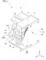
FIG. 1 is a perspective view of a camera device according to an embodiment of the present invention, and illustrates a state in which a shutter member is disposed in an open position. -
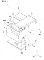
FIG. 2 is a perspective view of the camera device ofFIG. 1 , and illustrates a state in which the shutter member is disposed in a cover position. -
FIG. 3 is an exploded perspective view of the camera device ofFIG. 1 and2 . -
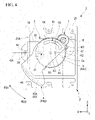
FIG. 4 is a diagram showing the positional relationship between the camera, the shutter member, and the power transmission member of the camera device ofFIG. 1 to 3 , and illustrates a state in which the power transmission member is located in a first rotation angle range, the shutter member is disposed in an open position, and the camera is facing in a forward direction. -
FIG. 5 is a perspective view showing the camera of the camera device ofFIG. 1 to 4 . -
FIG. 6 is a perspective view showing the shutter member of the camera device ofFIG. 1 to 4 . -
FIG. 7 is a perspective view showing the power transmission member of the camera device ofFIG. 1 to 4 . -
FIG. 8 is a diagram showing the positional relationship between the camera, the shutter member, and the power transmission member of the camera device ofFIG. 1 to 3 , and illustrates a state in which the power transmission member is located in the first rotation angle range, the shutter member is disposed in the open position, and the camera is facing in a diagonally upward direction. -
FIG. 9 is a diagram showing the positional relationship between the camera, the shutter member, and the power transmission member of the camera device ofFIG. 1 to 3 , and illustrates a state in which the power transmission member is located in the first rotation angle range, the shutter member is disposed in the open position, and the camera is facing in a diagonally downward direction. -
FIG. 10 is a diagram showing the positional relationship between the camera, the shutter member, and the power transmission member of the camera device ofFIG. 1 to 3 , and illustrates a state in which the power transmission member is located in a second rotation angle range, the shutter member is disposed in the open position, and the camera is facing in a diagonally downward direction. -
FIG. 11 is a diagram showing the positional relationship between the camera, the shutter member, and the power transmission member of the camera device ofFIG. 1 to 3 , and illustrates a state in which the power transmission member is located in the second rotation angle range, and the shutter member is disposed between the open position and the cover position. -
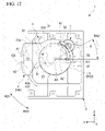
FIG. 12 is a diagram showing the positional relationship between the camera, the shutter member, and the power transmission member of the camera device ofFIG. 1 to 3 , and illustrates a state in which the power transmission member is located in the second rotation angle range, and the shutter member is disposed in the cover position. - Hereunder, embodiments of the present invention will be described with reference to
FIG. 1 to 12 . - As shown in
FIG. 1 to 4 , acamera device 1 includes abase member 2, acamera 3, ashutter member 4, apower transmission member 5, and amotor 6. Thecamera device 1 of the present embodiment further includes areduction gear mechanism 7. - The
base member 2 is configured so as to attach together thecamera 3, theshutter member 4, thepower transmission member 5, themotor 6, and thereduction gear mechanism 7. Thebase member 2 of the present embodiment is configured as a case that accommodates thecamera 3, thepower transmission member 5, themotor 6, and thereduction gear mechanism 7. - The
base member 2 includes abase body 21 and aside wall portion 22. InFIG. 4 , theside wall portion 22 is omitted. Thecamera 3, thepower transmission member 5, themotor 6, and thereduction gear mechanism 7 are mainly attached to thebase body 21. Thebase body 21 is formed with an opening portion (opening) 21A that allows thecamera 3 accommodated inside thebase body 21 to face the outside. - In the following description, the direction in which the
opening portion 21A of thebase body 21 faces (positive X-axis direction) may be referred to as the front, and the direction opposite to the front (negative X-axis direction) may be referred to as the rear. Furthermore, a first direction (Y-axis direction) orthogonal to the front-rear direction (X-axis direction) may be referred to as the width direction. Also, a second direction (Z-axis direction) orthogonal to the front-rear direction may be referred to as the up-down direction. Moreover, the positive Z-axis direction in the drawings may be referred to as up, and the negative Z-axis direction may be referred to as down. - The
side wall portion 22 is attached to one side of thebase body 21 in the width direction (positive Y-axis direction side), and covers thecamera 3, a portion of the shutter member 4 (a portion of a firstside plate portion 43A described below), thepower transmission member 5, themotor 6, and thereduction gear mechanism 7 attached to thebase body 21. - The
camera 3 shown inFIG. 1 to 5 captures images and videos. Thecamera 3 is rotatably attached to thebase member 2 about a first rotation axis A1. Furthermore, thecamera 3 has afirst locking groove 31 formed so as to extend in the radial direction of the first rotation axis A1. Hereunder, thecamera 3 of the present embodiment will be described in detail. - The
camera 3 of the present embodiment has acylindrical portion 32 whose interior is provided with a photography lens (not shown). The optical axis OA of thecamera 3 coincides with the central axis of thecylindrical portion 32. The optical axis OA may, for example, be positioned with an offset with respect to the central axis of thecylindrical portion 32. - The
camera 3 is disposed at the position of thebase member 2 where theopening portion 21A is formed. Thecamera 3 is rotatably attached to thebase member 2 about the first rotation axis A1. The first rotation axis A1 extends in a direction orthogonal to the optical axis OA at a first end portion of thecylindrical portion 32 in the longitudinal direction. In the present embodiment, the first rotation axis A1 extends in the width direction (Y-axis direction). Consequently, as thecamera 3 rotates with respect to thebase member 2, the direction in which the optical axis OA of thecamera 3 faces changes up and down (for example, seeFIG. 8 and9 ). In the present embodiment, as shown inFIG. 1 and5 , ashaft body 33 that constitutes the first rotation axis A1 is provided on thecamera 3, and ahole 34 into which theshaft body 33 is inserted is formed in thebase member 2. However, the embodiment of the present invention is not limited to such a configuration. - As shown in
FIG. 3 and4 , thecamera 3 is disposed such that thecylindrical portion 32 extends from theopening portion 21A of thebase member 2 to the inside (rear) of thebase member 2. As shown inFIG. 3 to 5 , thefirst locking groove 31 of thecamera 3 is located in a second end portion of thecylindrical portion 32 in the longitudinal direction, which is located more to the inside (rear) than theopening portion 21A of thebase member 2. Furthermore, thefirst locking groove 31 is located on one side of thecylindrical portion 32 in the width direction (positive Y-axis direction side). Thefirst locking groove 31 extends linearly in the longitudinal direction of thecylindrical portion 32, and is open on the second end portion side of thecylindrical portion 32 in the longitudinal direction of thecylindrical portion 32. - The
shutter member 4 shown inFIG. 1 to 4 andFIG. 6 is a member for covering thecamera 3, and is rotatably attached to thebase member 2 about a second rotation axis A2 that is different from and is parallel to the first rotation axis A1. As a result of rotating about the second rotation axis A2, theshutter member 4 is capable of moving between a cover position P41, in which thecamera 3 is covered as shown inFIG. 2 , and an open position P42, in which thecamera 3 is exposed to the outside as shown inFIG. 1 and4 . As shown inFIG. 3 and4 , theshutter member 4 includes asecond locking groove 41 formed in an arc shape when viewed from the direction in which the second rotation axis A2 extends (width direction). Hereunder, theshutter member 4 of the present embodiment will be described in detail. - As shown in
FIG. 1 to 4 andFIG. 6 , theshutter member 4 of the present embodiment includes ashutter body 42, and a pair ofside plate portions 43. - The
shutter body 42 is a part for covering thecamera 3. Theshutter body 42 is located away from the second rotation axis A2 in the radial direction, and has a curved plate shape so as to form an arc shape centered on the second rotation axis A2 when viewed from the width direction as shown inFIG. 4 . The second rotation axis A2 is located away from, and more to the rear (negative X-axis direction) than the first rotation axis A1. - As shown in
FIG. 2 and12 , when theshutter member 4 is disposed in the cover position P41, theshutter body 42 is located in front of theopening portion 21A of thebase member 2. As a result, theshutter body 42 covers thecamera 3. On the other hand, as shown inFIG. 1 and4 , when theshutter member 4 is disposed in the open position P42, theshutter body 42 is located below theopening portion 21A of thebase member 2. As a result, theshutter body 42 does not cover thecamera 3. - As shown in
FIG. 4 and12 , when theshutter body 42 is viewed from one side in the width direction (positive Y-axis direction side), the cover position P41 of theshutter body 42 is located so as to be away from the open position P42 in a clockwise direction (hereunder referred to as a first rotation direction RD1). - As shown in
FIG. 1 to 3 andFIG. 6 , the pair ofside plate portions 43 is formed with a plate shape extending in the radial direction of the second rotation axis A2 from both ends of theshutter body 42 in the width direction (Y-axis direction) toward the second rotation axis A2 side. The plate thickness direction of eachside plate portion 43 is oriented in the width direction. The pair ofside plate portions 43 is located with a spacing in the width direction. The pair ofside plate portions 43 is located on both sides of thecamera 3 in the width direction when theshutter member 4 is attached to thebase member 2. - As shown in
FIG. 3 and6 , holes 45 into which ashaft body 44 constituting the second rotation axis A2 is inserted are formed in the pair ofside plate portions 43. Theshaft body 44, which is provided on theside wall portion 22 of thebase member 2, is inserted into thehole 45 of a firstside plate portion 43A, which of the pair ofside plate portions 43 is located on one side in the width direction (positive Y-axis direction side). - As shown in
FIG. 3 to 5 , thesecond locking groove 41 of theshutter member 4 is formed in the firstside plate portion 43A. Thesecond locking groove 41 is formed with an arc shape centered on a third rotation axis A3 of thepower transmission member 5 described below when theshutter member 4 is disposed in the open position P42. As shown inFIG. 4 , when viewed from the one side in the width direction (positive Y-axis direction side), a first end portion 411 (end portion in the longitudinal direction of the second locking groove 41) is formed with anindentation 47. Thefirst end portion 411 is located on the first rotation direction RD1 side of thesecond locking groove 41. Theindentation 47 extends in a radially inward direction of thesecond locking groove 41 having an arc shape. - The
power transmission member 5 shown inFIG. 3 and4 is rotatably attached to thebase member 2 about the third rotation axis A3 that is different from and parallel to the first rotation axis A1. In the present embodiment, the third rotation axis A3 of thepower transmission member 5 is located with an offset with respect to not only the first rotation axis A1, but also the second rotation axis A2. As shown inFIG. 4 ,8 , and9 , thepower transmission member 5 causes thecamera 3 to rotate together with the rotation of thepower transmission member 5 when located in a first rotation angle range RA1. Furthermore, as shown inFIG. 10 to 12 , thepower transmission member 5 causes theshutter member 4 to rotate together with the rotation of thepower transmission member 5 when located in a second rotation angle range RA2, which is different from the first rotation angle range RA1. Hereunder, thepower transmission member 5 of the present embodiment will be described in detail. - As shown in
FIG. 3 and7 , thepower transmission member 5 of the present embodiment is a gear formed with a circular plate shape centered on the third rotation axis A3. Ahole 55 into which ashaft body 54 constituting the third rotation axis A3 is inserted, is formed in the center of thepower transmission member 5. In the present embodiment, theshaft body 54 constituting the third rotation axis A3 is provided on thebase body 21. - The
power transmission member 5 is disposed between thecamera 3 and the firstside plate portion 43A of theshutter member 4 in the width direction, with the plate thickness direction of thepower transmission member 5 oriented in the width direction. As a result, thepower transmission member 5 is located on the one side in the width direction (positive Y-axis direction side) with respect to thecamera 3. In this state, the third rotation axis A3 of thepower transmission member 5 is located between the first rotation axis A1 and the second rotation axis A2 in the front-rear direction. The third rotation axis A3 is located closer to the second rotation axis A2 than the first rotation axis A1 in the front-rear direction. - As shown in
FIG. 3 ,4 , and7 , thepower transmission member 5 includes afirst locking pin 51, asecond locking pin 52, and asupport pin 53. Thefirst locking pin 51, thesecond locking pin 52, and thesupport pin 53 are each located away from the third rotation axis A3 in the radial direction. Moreover, thefirst locking pin 51, thesecond locking pin 52, and thesupport pin 53 are disposed with a spacing from each other in the circumferential direction of the third rotation axis A3. - The
first locking pin 51 and thesupport pin 53 are provided on a first facingsurface 5a, which is a surface of thepower transmission member 5 facing thecamera 3 in the width direction (Y-axis direction). On the other hand, thesecond locking pin 52 is provided on a second facingsurface 5b, which is a surface of thepower transmission member 5 facing the firstside plate portion 43A of theshutter member 4 in the width direction (Y-axis direction). - As shown in
FIG. 4 ,8 , and9 , thefirst locking pin 51 is inserted into thefirst locking groove 31 of thecamera 3 when the power transmission member 5 (thesecond locking pin 52 of the power transmission member 5) is located in the first rotation angle range RA1. In this state, thepower transmission member 5 engages thecamera 3, and thecamera 3 rotates about the first rotation axis A1 together with the rotation of thepower transmission member 5 about the third rotation axis A3. On the other hand, as shown inFIG. 10 to 12 , when thepower transmission member 5 is located outside the first rotation angle range RA1, thefirst locking pin 51 of thepower transmission member 5 becomes free from (moves out of) anopen end 31A of thefirst locking groove 31 located on the second end portion side of thecamera 3, and the engaged state between thepower transmission member 5 and thecamera 3 is released. In this state, even if thepower transmission member 5 rotates, thecamera 3 does not rotate. - That is to say, as shown in
FIG. 8 and9 , the first rotation angle range RA1 of thepower transmission member 5 corresponds to a rotation angle range of thefirst locking pin 51 that results in a state where thefirst locking pin 51 is inserted into thefirst locking groove 31 of the camera 3 (that is to say, a state in which thepower transmission member 5 engages with the camera 3). - Hereinafter, the mechanism by which the rotation of the
power transmission member 5 and the rotation of the camera 3 (tilt mechanism of the camera 3) are linked will be further described. - In the present embodiment, the first rotation axis A1 and the third rotation axis A3 are located in line in the front-rear direction when viewed from the width direction as shown in
FIG. 4 ,8 , and9 . Furthermore, thefirst locking groove 31 of thecamera 3 is located between the first rotation axis A1 and the third rotation axis A3 in the front-rear direction, and extends in the radial direction of the first rotation axis A1. - As shown in
FIG. 4 , when thefirst locking pin 51 inserted into thefirst locking groove 31 of thecamera 3 is located between the first rotation axis A1 and the third rotation axis A3, the optical axis OA of thecamera 3 faces the front (positive X-axis direction). - As shown in
FIG. 8 , when thepower transmission member 5 is rotated in an anticlockwise direction about the third rotation axis A3 (hereunder referred to as a second rotation direction RD2) from the state shown inFIG. 4 , thecamera 3 rotates in the first rotation direction RD1 about the first rotation axis A1. As a result, the optical axis OA of thecamera 3 faces diagonally upward. - On the other hand, as shown in
FIG. 9 , when thepower transmission member 5 is rotated in the first rotation direction RD1 about the third rotation axis A3 from the state shown inFIG. 4 , thecamera 3 rotates in the second rotation direction RD2 about the first rotation axis A1. As a result, the optical axis OA of thecamera 3 faces diagonally downward. - As shown in
FIG. 10 and11 , when thepower transmission member 5 is rotated further in the first rotation direction RD1 from the state shown inFIG. 9 , thefirst locking pin 51 of thepower transmission member 5 becomes free from (moves out of) theopen end 31A of thefirst locking groove 31 located on the second end portion side of thecamera 3, and the engaged state between thepower transmission member 5 and thecamera 3 is released. - As shown in
FIG. 4 and8 to 12 , thesecond locking pin 52 is inserted into thesecond locking groove 41 formed in the firstside plate portion 43A of theshutter member 4. - As shown in
FIG. 4 ,8 , and9 , when the power transmission member 5 (thesecond locking pin 52 of the power transmission member 5) is located in the first rotation angle range RA1, theshutter member 4 is disposed in the open position P42, and thesecond locking groove 41 of theshutter member 4 has an arc shape centered on the third rotation axis A3. Consequently, when thepower transmission member 5 is located in the first rotation angle range RA1 (that is to say, is located outside the second rotation angle range RA2 described below), thesecond locking pin 52 is capable of moving in the longitudinal direction of thesecond locking groove 41 together with the rotation of thepower transmission member 5. That is to say, when thepower transmission member 5 is located in the first rotation angle range RA1, the engagement between thepower transmission member 5 and theshutter member 4 is released, and theshutter member 4 does not rotate even if thepower transmission member 5 rotates.FIG. 8 and9 show the rotation angle range of thesecond locking pin 52 that corresponds to the first rotation angle range RA1 of the power transmission member 5 (the rotation angle range of the first locking pin 51). The rotation angle range of thesecond locking pin 52 corresponding to the first rotation angle range RA1 is included in the movable range of thesecond locking pin 52 in the longitudinal direction of thesecond locking groove 41. - As shown in
FIG. 10 to 12 , when the power transmission member 5(thesecond locking pin 52 of the power transmission member 5) is located in the second rotation angle range RA2, which is different from the first rotation angle range RA1, thesecond locking pin 52 of thepower transmission member 5 makes contact with the first end portion 411 (end portion) in the longitudinal direction of thesecond locking groove 41 of theshutter member 4. In this state, thepower transmission member 5 engages with theshutter member 4, and theshutter member 4 rotates about the second rotation axis A2 together with the rotation of thepower transmission member 5 about the third rotation axis A3. Furthermore, in this state, thefirst locking pin 51 is free from (moves out of) thefirst locking groove 31 of thecamera 3. - The second rotation angle range RA2 of the
power transmission member 5 corresponds to a rotation angle range of thesecond locking pin 52 that results in a state where thesecond locking pin 52 makes contact with thefirst end portion 411 of thesecond locking groove 41 of theshutter member 4. Furthermore, the second rotation angle range RA2 of thepower transmission member 5 corresponds to a rotation angle range of theshutter member 4 from the open position P42 up to the cover position P41 of theshutter member 4. - As shown in
FIG. 10 , the first rotation angle range RA1 and the second rotation angle range RA2 of thepower transmission member 5 are adjacently located in the circumferential direction of thepower transmission member 5, which is centered on the third rotation axis A3. Specifically, the first rotation angle range RA1 and the second rotation angle range RA2 are arranged in order in the first rotation direction RD1. The first rotation angle range RA1 and the second rotation angle range RA2 may, for example, be arranged without a spacing. However, in the present embodiment, they are arranged with a spacing. - As a result, as shown in
FIG. 9 and10 , when thepower transmission member 5 is rotated in the first rotation direction RD1 from the first rotation angle range RA1 toward the second rotation angle range RA2, thefirst locking pin 51 becomes free from (moves out of) thefirst locking groove 31. Then, when thepower transmission member 5 further rotates in the first rotation direction RD1, thesecond locking pin 52 makes contact with thefirst end portion 411 of thesecond locking groove 41. - In contrast, when the
power transmission member 5 is rotated in the second rotation direction RD2 from the second rotation angle range RA2 toward the first rotation angle range RA1, thesecond locking pin 52 separates from thefirst end portion 411 of thesecond locking groove 41. Then, when thepower transmission member 5 further rotates in the second rotation direction RD2, thefirst locking pin 51 is inserted into thefirst locking groove 31. - Hereinafter, the mechanism by which the rotation of the
power transmission member 5 and the rotation of theshutter member 4 are linked will be further described. - As shown in
FIG. 10 , when theshutter member 4 is disposed in the open position P42, and thepower transmission member 5 rotates inside the second rotation angle range RA2 in the first rotation direction RD1, thesecond locking pin 52, which is in contact with thefirst end portion 411 of thesecond locking groove 41, pushes and rotates theshutter member 4 in the first rotation direction RD1. As a result, as shown inFIG. 10 to 12 , theshutter member 4 moves from the open position P42 toward the cover position P41. - Here, as described above, the
second locking groove 41 has an arc shape centered on the third rotation axis A3 when theshutter member 4 is disposed in theopen position 42. Furthermore, the second rotation axis A2 of theshutter member 4 and the third rotation axis A3 of thepower transmission member 5 are located such that they are offset from each other. Consequently, theshutter member 4 rotationally moves from the open position P42 to the cover position P41 in conjunction with the rotation of thepower transmission member 5 in the first rotation direction RD1. As a result, thesecond locking pin 52 in contact with thefirst end portion 411 of thesecond locking groove 41 moves in the radially inward direction with respect to thesecond locking groove 41, and is inserted into theindentation 47 formed in thefirst end portion 411 of thesecond locking groove 41. - On the other hand, as shown in
FIG. 12 , when theshutter member 4 is disposed in the cover position P41, and thepower transmission member 5 rotates inside the second rotation angle range RA2 in the second rotation direction RD2, thesecond locking pin 52 inserted into theindentation 47 of thefirst end portion 411 of thesecond locking groove 41 pushes and rotates theshutter member 4 in the second rotation direction RD2. As a result, as shown inFIG. 10 to 12 , theshutter member 4 moves from the cover position P41 toward the open position P42. - As shown in
FIG. 10 , when theshutter member 4 reaches the open position P42, thesecond locking pin 52 becomes free from (moves out of) theindentation 47 in thefirst end portion 411 of thesecond locking groove 41. As a result, even when thepower transmission member 5 is further rotated in the second rotation direction RD2, thesecond locking pin 52 does not push theshutter member 4 in the second rotation direction RD2. That is to say, theshutter member 4 does not further rotate in the second rotation direction RD2 from the open position P42. - As shown in
FIG. 10 to 12 , thesupport pin 53 supports thecamera 3 so as to suppress a rotation of thecamera 3 about the first rotation axis A1 when thepower transmission member 5 located in the second rotation angle range RA2. Furthermore, as shown inFIG. 4 ,8 , and9 , thesupport pin 53 is located away from thecamera 3 so as to not interfere with the rotation of thecamera 3 when thepower transmission member 5 is located in the first rotation angle range RA1. - Hereinafter, the specific mode by which the
camera 3 is supported by thesupport pin 53 will be described. - As shown in
FIG. 10 to 12 , when thepower transmission member 5 is located in the second rotation angle range RA2 and rotates in the first rotation direction RD1, and moves theshutter member 4 from the open position P42 to the cover position P41, thesupport pin 53 located below thecamera 3 upwardly moves so as to approach thecylindrical portion 32 of thecamera 3. As a result, thesupport pin 53 supports from below the part of thecylindrical portion 32 of thecamera 3 located more to the inside (rear) of thebase member 2 than the first rotation axis A1. In this state, thesupport pin 53 keeps the optical axis OA of thecamera 3 facing diagonally downward. That is to say, the orientation of thecamera 3 can be maintained within a predetermined range when thefirst locking pin 51 of thepower transmission member 5 is free from (moves out of) thefirst locking groove 31 of thecamera 3. - The
motor 6 rotationally drives thepower transmission member 5 described above. Themotor 6 may, for example, directly drive the third rotation axis A3 of thepower transmission member 5. In the present embodiment, themotor 6 rotationally drives thepower transmission member 5 via thereduction gear mechanism 7. Thereduction gear mechanism 7 transmits the drive force of themotor 6 to thepower transmission member 5 such that the rotation speed of thepower transmission member 5 is lower than the rotation speed of themotor 6. - As described above, in the
camera device 1 of the present embodiment, when thepower transmission member 5 rotates inside the first rotation angle range RA1, thecamera 3 rotates in conjunction with the rotation of thepower transmission member 5, and theshutter member 4 does not rotate. On the other hand, when thepower transmission member 5 rotates inside the second rotation angle range RA2, theshutter member 4 rotates in conjunction with the rotation of thepower transmission member 5, and thecamera 3 does not rotate. - As a result, when the
power transmission member 5 rotates, thecamera 3 and theshutter member 4 do not move at the same time. That is to say, thecamera 3 and theshutter member 4 can be moved independently by thesame motor 6 andpower transmission member 5. Therefore, it is possible to independently move thecamera 3 and theshutter member 4, while also reducing in the number of components of thecamera device 1 and simplifying the structure of thecamera device 1. Furthermore, because thecamera device 3 and theshutter member 4 can be independently moved using thesame motor 6, a reduction in the cost of thecamera device 1 can be achieved by reducing the number ofmotors 6 and simplifying the structure of thecamera device 1 compared with a conventional device. - Moreover, as shown in
FIG. 10 to 12 , in thecamera device 1 of the present embodiment, when thepower transmission member 5 rotates inside the second rotation angle range RA2 in the second rotation direction RD2 so as to approach the first rotation angle range RA1, theshutter member 4 moves from the cover position P41 toward the open position P42. Therefore, when thepower transmission member 5 rotates in the second rotation direction RD2 and shifts from the second rotation angle range RA2 to the first rotation angle range RA1, theshutter member 4 is disposed in the open position P42. As a result, when thepower transmission member 5 rotates inside the first rotation angle range RA1, the orientation of thecamera 3 can be changed by rotating thecamera 3 together with the rotation of thepower transmission member 5 while theshutter member 4 is disposed in the open position P42 (a state where theshutter member 4 is not covering the camera 3). That is to say, the direction (region) captured by thecamera 3 can be changed. - Furthermore, in the
camera device 1 of the present embodiment, because thepower transmission member 5 engages with thecamera 3 in the first rotation angle range RA1, thecamera 3 rotates together with the rotation of thepower transmission member 5. On the other hand, when thepower transmission member 5 is located outside the first rotation angle range RA1, the engagement between thecamera 3 and thepower transmission member 5 is released, and thus thecamera 3 does not rotate together with the rotation of thepower transmission member 5. Moreover, because thepower transmission member 5 engages with theshutter member 4 in the second rotation angle range RA2, theshutter member 4 rotates together with the rotation of thepower transmission member 5. On the other hand, when thepower transmission member 5 is located outside the second rotation angle range RA2, the engagement between theshutter member 4 and thepower transmission member 5 is released, and theshutter member 4 does not rotate together with the rotation of thepower transmission member 5. - Further, in the
camera device 1 of the present embodiment, thepower transmission member 5 and thecamera device 3 are engaged as a result of thefirst locking pin 51 of thepower transmission member 5 being inserted into thefirst locking groove 31 of thecamera device 3. In addition, thepower transmission member 5 and theshutter member 4 are engaged as a result of thesecond locking pin 52 of thepower transmission member 5 making contact with thefirst end portion 411 of thesecond locking groove 41 of theshutter member 4. - With such a specific structure, the
camera 3 and theshutter member 4 can be moved separately, and not simultaneously, by thesame motor 6 with certainty. - Furthermore, in the
camera device 1 of the present embodiment, thepower transmission member 5 has thesupport pin 53 that supports thecamera 3 so as to suppress a rotation of thecamera 3 about the first rotation axis A1 when located in the second rotation angle range RA2. Consequently, as a result of thepower transmission member 5 rotationally moving from the first rotation angle range RA1 to the second rotation angle range RA2, the position (posture) of thecamera 3 is maintained by thesupport pin 53 even when thefirst locking pin 51 of thepower transmission member 5 is free from (moves out of) thefirst locking groove 31 of thecamera 3. As a result, when thepower transmission member 5 rotationally moves from the second rotation angle range RA2 to the first rotation angle range RA1, thefirst locking pin 51 of thepower transmission member 5 can be inserted into thefirst locking groove 31 of thecamera 3 with certainty. - The embodiments of present invention have been described in detail above. However, the present invention is not limited to the embodiments above, and various changes may be applied within a scope not departing from the spirit of the present invention.
- In the camera device of the present invention, for example, the second rotation axis A2 of the
shutter member 4 and the third rotation axis A3 of thepower transmission member 5 may coincide with each other. - According to an embodiment of the present invention, it is possible to independently move a camera and a shutter with the drive force of the same motor, while also reducing the number of components of the camera device and simplifying the structure.
- The present invention has been described in detail above. However, the present invention is not limited to the embodiments above, and various modifications may be made to the above configurations without departing from the scope of the invention
Claims (7)
- A camera device comprising:a base member;a camera which is rotatably attached to the base member about a first rotation axis;a shutter member which is rotatably attached to the base member about a second rotation axis, the second rotation axis being different from the first rotation axis and being parallel to the first rotation axis, the shutter member being rotatable between a cover position in which the shutter member covers the camera, and an open position in which the shutter member does not cover the camera;a power transmission member which is rotatably attached to the base member about a third rotation axis, the third rotation axis being different from the first rotation axis and being parallel to the first rotation axis; anda motor configured to rotationally drive the power transmission member;wherein the power transmission member causes the camera to rotate together with a rotation of the power transmission member in a first rotation angle range of the power transmission member, andwherein the power transmission member causes the shutter member to rotate together with a rotation of the power transmission member in a second rotation angle range of the power transmission member, the second rotation angle range being different from the first rotation angle range.
- The camera device according to claim 1,wherein the first rotation angle range and the second rotation angle range of the power transmission member are adjacently positioned in a circumferential direction of the rotation of the power transmission member,wherein the shutter member moves from the open position toward the cover position when the rotation of the power transmission member is within the second rotation angle range in a first rotation direction, the first rotation direction being a direction from the first rotation angle range toward the second rotation angle range, andwherein the shutter member moves from the cover position toward the open position when the rotation of the power transmission member is within the second rotation angle range in a second rotation direction, the second rotation direction being an opposite direction to the first rotation direction.
- The camera device according to claim 1 or 2, wherein the camera rotates together with the rotation of the power transmission member by the power transmission member engaging with the camera when the power transmission member is rotating in the first rotation angle range.
- The camera device according to any one of claims 1 to 3, wherein the shutter member rotates together with the rotation of the power transmission member by the power transmission member engaging with the shutter member when the power transmission member is rotating in the second rotation angle range.
- The camera device according to any one of claims 1 to 4,wherein the power transmission member includes a first locking pin and a second locking pin that are located at positions separated from the third rotation axis in a radial direction of the third rotation axis, the first locking pin and the second locking pin being spaced apart from each other in a circumferential direction of the third rotation axis,wherein the camera includes a first locking groove that extends in a radial direction of the first rotation axis,wherein the first locking pin is inserted in the first locking groove when the rotation of the power transmission member is within the first rotation angle range, and the first locking pin is not inserted in the first locking groove when the rotation of the power transmission member is within the second rotation angle range, andwherein the camera rotates together with the rotation of the power transmission member when the first locking pin is inserted in the first locking groove.
- The camera device according to any one of claims 1 to 4,wherein the power transmission member includes a first locking pin and a second locking pin that are located at positions separated from the third rotation axis in a radial direction of the third rotation axis, the first locking pin and the second locking pin being spaced apart from each other in a circumferential direction of the third rotation axis,wherein the shutter member has an arc shape centered on the third rotation axis, and includes a second locking groove into which the second locking pin is inserted when the shutter member is located in the open position,wherein the second locking pin is movable in a longitudinal direction of the second locking groove when the rotation of the power transmission member is within the first rotation angle range, and the second locking pin contacts an end portion of the second locking groove in the longitudinal direction when the rotation of the power transmission member is within the second rotation angle range, andwherein the shutter member rotates together with the rotation of the power transmission member by the second locking pin contacting the end portion of the second locking groove.
- The camera device according to claim 5 or 6, wherein the power transmission member includes a support pin that supports the camera so as to suppress a rotation of the camera about the first rotation axis when the rotation of the power transmission member is within the second rotation angle range.
Applications Claiming Priority (1)
| Application Number | Priority Date | Filing Date | Title |
|---|---|---|---|
| JP2021032272A JP7615770B2 (en) | 2021-03-02 | 2021-03-02 | Camera equipment |
Publications (2)
| Publication Number | Publication Date |
|---|---|
| EP4053629A1 true EP4053629A1 (en) | 2022-09-07 |
| EP4053629B1 EP4053629B1 (en) | 2026-04-01 |
Family
ID=80461600
Family Applications (1)
| Application Number | Title | Priority Date | Filing Date |
|---|---|---|---|
| EP22158632.4A Active EP4053629B1 (en) | 2021-03-02 | 2022-02-24 | Camera device |
Country Status (5)
| Country | Link |
|---|---|
| US (1) | US11747713B2 (en) |
| EP (1) | EP4053629B1 (en) |
| JP (1) | JP7615770B2 (en) |
| CN (1) | CN117296008A (en) |
| WO (1) | WO2022185297A1 (en) |
Citations (5)
| Publication number | Priority date | Publication date | Assignee | Title |
|---|---|---|---|---|
| GB253142A (en) * | 1925-06-05 | 1927-12-07 | Umberto Nistri | Improvements in film photographic cameras |
| GB917875A (en) * | 1957-12-30 | 1963-02-06 | Lidia Bettini Jacomelli | Improvements in or relating to photographic type composing |
| US4878138A (en) * | 1986-12-04 | 1989-10-31 | Fuji Photo Film Co., Ltd. | Recording medium loading mechanism for guiding a recording medium to a recording/reproducing position |
| JP2010107772A (en) | 2008-10-30 | 2010-05-13 | Victor Co Of Japan Ltd | Tilt mechanism of monitoring camera apparatus |
| US20150268534A1 (en) * | 2010-11-10 | 2015-09-24 | Panasonic Intellectual Property Management Co., Ltd. | Dome camera |
Family Cites Families (8)
| Publication number | Priority date | Publication date | Assignee | Title |
|---|---|---|---|---|
| US4833534A (en) * | 1988-02-19 | 1989-05-23 | Sensormatic Electronics Corporation | Surveillance assembly having enhanced shielding and reduced size |
| US7039311B2 (en) * | 2002-08-27 | 2006-05-02 | Pentax Corporation | Rotation transfer mechanism and a zoom camera incorporating the rotation transfer mechanism |
| JP4487216B2 (en) * | 2008-01-18 | 2010-06-23 | ソニー株式会社 | Lens barrel and imaging device |
| TWI522721B (en) * | 2014-04-03 | 2016-02-21 | Topview Optronics Corp | Monitoring system Camera light source module Shading device |
| JP2016057586A (en) * | 2014-09-12 | 2016-04-21 | パナソニックIpマネジメント株式会社 | Camera device and method of controlling camera device |
| CN109154761B (en) * | 2016-04-28 | 2021-02-09 | 富士胶片株式会社 | digital camera |
| DE102017123153A1 (en) * | 2017-10-05 | 2019-04-11 | Huf Hülsbeck & Fürst Gmbh & Co. Kg | Automotive adjustment device |
| KR102719039B1 (en) * | 2019-08-05 | 2024-10-17 | 한화비전 주식회사 | Camera apparatus and photography system having the same |
-
2021
- 2021-03-02 JP JP2021032272A patent/JP7615770B2/en active Active
-
2022
- 2022-02-24 EP EP22158632.4A patent/EP4053629B1/en active Active
- 2022-02-25 US US17/680,635 patent/US11747713B2/en active Active
- 2022-04-28 WO PCT/IB2022/053934 patent/WO2022185297A1/en not_active Ceased
- 2022-04-28 CN CN202280031955.6A patent/CN117296008A/en active Pending
Patent Citations (5)
| Publication number | Priority date | Publication date | Assignee | Title |
|---|---|---|---|---|
| GB253142A (en) * | 1925-06-05 | 1927-12-07 | Umberto Nistri | Improvements in film photographic cameras |
| GB917875A (en) * | 1957-12-30 | 1963-02-06 | Lidia Bettini Jacomelli | Improvements in or relating to photographic type composing |
| US4878138A (en) * | 1986-12-04 | 1989-10-31 | Fuji Photo Film Co., Ltd. | Recording medium loading mechanism for guiding a recording medium to a recording/reproducing position |
| JP2010107772A (en) | 2008-10-30 | 2010-05-13 | Victor Co Of Japan Ltd | Tilt mechanism of monitoring camera apparatus |
| US20150268534A1 (en) * | 2010-11-10 | 2015-09-24 | Panasonic Intellectual Property Management Co., Ltd. | Dome camera |
Also Published As
| Publication number | Publication date |
|---|---|
| US11747713B2 (en) | 2023-09-05 |
| EP4053629B1 (en) | 2026-04-01 |
| US20220283478A1 (en) | 2022-09-08 |
| WO2022185297A1 (en) | 2022-09-09 |
| JP2022133541A (en) | 2022-09-14 |
| CN117296008A (en) | 2023-12-26 |
| JP7615770B2 (en) | 2025-01-17 |
Similar Documents
| Publication | Publication Date | Title |
|---|---|---|
| US8456754B2 (en) | Zoom lens barrel | |
| EP3561589B1 (en) | Image stabilization apparatus, lens apparatus, and camera system | |
| CN101126832A (en) | Lens barrel | |
| JP2006058455A (en) | Lens barrel driving mechanism | |
| US9798158B2 (en) | Optical apparatus capable of retracting optical element from optical path | |
| EP4053629B1 (en) | Camera device | |
| JPH06148494A (en) | Mirror frame supporting mechanism | |
| JP2005308810A (en) | Lens barrel and imaging device | |
| JP4586000B2 (en) | Cradle with pan head function | |
| JP5328233B2 (en) | Barrier device, lens barrel, camera | |
| JP2005234446A (en) | Tilt-type camera device | |
| JP2019056858A (en) | Imaging device | |
| JP2005189516A (en) | Lens barrel driving mechanism | |
| JP2011154201A (en) | Photographing device | |
| JP2000266981A (en) | Lens barrel | |
| JP7486647B1 (en) | Imaging device and camera | |
| JP7460409B2 (en) | lens drive device | |
| JP4882321B2 (en) | Lens barrel | |
| JP4766664B2 (en) | Lens barrel | |
| JPH0961887A (en) | Optical equipment | |
| JP2011033818A (en) | Barrier unit, lens barrel and camera | |
| JP2004045744A (en) | Barrier device | |
| JP2013025259A (en) | Position control device of retreating optical element | |
| JP5515786B2 (en) | Imaging device | |
| JP2006349799A (en) | Lens barrel driving mechanism |
Legal Events
| Date | Code | Title | Description |
|---|---|---|---|
| PUAI | Public reference made under article 153(3) epc to a published international application that has entered the european phase |
Free format text: ORIGINAL CODE: 0009012 |
|
| STAA | Information on the status of an ep patent application or granted ep patent |
Free format text: STATUS: THE APPLICATION HAS BEEN PUBLISHED |
|
| AK | Designated contracting states |
Kind code of ref document: A1 Designated state(s): AL AT BE BG CH CY CZ DE DK EE ES FI FR GB GR HR HU IE IS IT LI LT LU LV MC MK MT NL NO PL PT RO RS SE SI SK SM TR |
|
| STAA | Information on the status of an ep patent application or granted ep patent |
Free format text: STATUS: REQUEST FOR EXAMINATION WAS MADE |
|
| 17P | Request for examination filed |
Effective date: 20230227 |
|
| RBV | Designated contracting states (corrected) |
Designated state(s): AL AT BE BG CH CY CZ DE DK EE ES FI FR GB GR HR HU IE IS IT LI LT LU LV MC MK MT NL NO PL PT RO RS SE SI SK SM TR |
|
| STAA | Information on the status of an ep patent application or granted ep patent |
Free format text: STATUS: EXAMINATION IS IN PROGRESS |
|
| 17Q | First examination report despatched |
Effective date: 20241016 |
|
| GRAP | Despatch of communication of intention to grant a patent |
Free format text: ORIGINAL CODE: EPIDOSNIGR1 |
|
| STAA | Information on the status of an ep patent application or granted ep patent |
Free format text: STATUS: GRANT OF PATENT IS INTENDED |
|
| INTG | Intention to grant announced |
Effective date: 20251031 |
|
| GRAS | Grant fee paid |
Free format text: ORIGINAL CODE: EPIDOSNIGR3 |
|
| GRAA | (expected) grant |
Free format text: ORIGINAL CODE: 0009210 |
|
| STAA | Information on the status of an ep patent application or granted ep patent |
Free format text: STATUS: THE PATENT HAS BEEN GRANTED |
|
| AK | Designated contracting states |
Kind code of ref document: B1 Designated state(s): AL AT BE BG CH CY CZ DE DK EE ES FI FR GB GR HR HU IE IS IT LI LT LU LV MC MK MT NL NO PL PT RO RS SE SI SK SM TR |
|
| REG | Reference to a national code |
Ref country code: CH Ref legal event code: F10 Free format text: ST27 STATUS EVENT CODE: U-0-0-F10-F00 (AS PROVIDED BY THE NATIONAL OFFICE) Effective date: 20260401 Ref country code: GB Ref legal event code: FG4D |
|
| REG | Reference to a national code |
Ref country code: IE Ref legal event code: FG4D |
|
| REG | Reference to a national code |
Ref country code: DE Ref legal event code: R096 Ref document number: 602022033285 Country of ref document: DE |