WO2017188252A1 - Digital camera - Google Patents
Digital camera Download PDFInfo
- Publication number
- WO2017188252A1 WO2017188252A1 PCT/JP2017/016380 JP2017016380W WO2017188252A1 WO 2017188252 A1 WO2017188252 A1 WO 2017188252A1 JP 2017016380 W JP2017016380 W JP 2017016380W WO 2017188252 A1 WO2017188252 A1 WO 2017188252A1
- Authority
- WO
- WIPO (PCT)
- Prior art keywords
- digital camera
- unit
- battery
- shutter
- curtain
- Prior art date
Links
- 230000011514 reflex Effects 0.000 claims description 14
- 238000003780 insertion Methods 0.000 claims description 9
- 230000037431 insertion Effects 0.000 claims description 9
- 239000000758 substrate Substances 0.000 claims description 8
- 230000009471 action Effects 0.000 abstract description 3
- 230000003287 optical effect Effects 0.000 description 14
- 230000005540 biological transmission Effects 0.000 description 6
- 230000007246 mechanism Effects 0.000 description 6
- 238000000034 method Methods 0.000 description 5
- 210000003813 thumb Anatomy 0.000 description 5
- 230000000694 effects Effects 0.000 description 3
- 241001047198 Scomberomorus semifasciatus Species 0.000 description 2
- 235000012467 brownies Nutrition 0.000 description 2
- 238000006243 chemical reaction Methods 0.000 description 2
- 210000003811 finger Anatomy 0.000 description 2
- 238000004519 manufacturing process Methods 0.000 description 2
- GGCZERPQGJTIQP-UHFFFAOYSA-N sodium;9,10-dioxoanthracene-2-sulfonic acid Chemical compound [Na+].C1=CC=C2C(=O)C3=CC(S(=O)(=O)O)=CC=C3C(=O)C2=C1 GGCZERPQGJTIQP-UHFFFAOYSA-N 0.000 description 2
- 230000000295 complement effect Effects 0.000 description 1
- 230000008878 coupling Effects 0.000 description 1
- 238000010168 coupling process Methods 0.000 description 1
- 238000005859 coupling reaction Methods 0.000 description 1
- 230000003247 decreasing effect Effects 0.000 description 1
- 238000005286 illumination Methods 0.000 description 1
- 239000004973 liquid crystal related substance Substances 0.000 description 1
- 238000005259 measurement Methods 0.000 description 1
- 229910052751 metal Inorganic materials 0.000 description 1
- 239000002184 metal Substances 0.000 description 1
- 230000004048 modification Effects 0.000 description 1
- 238000012986 modification Methods 0.000 description 1
- 239000002245 particle Substances 0.000 description 1
- 238000005375 photometry Methods 0.000 description 1
- 239000004065 semiconductor Substances 0.000 description 1
- 230000035939 shock Effects 0.000 description 1
- 229910052709 silver Inorganic materials 0.000 description 1
- 239000004332 silver Substances 0.000 description 1
- -1 silver halide Chemical class 0.000 description 1
- 230000006641 stabilisation Effects 0.000 description 1
- 238000011105 stabilization Methods 0.000 description 1
- 230000002195 synergetic effect Effects 0.000 description 1
- 238000004804 winding Methods 0.000 description 1
Images


Classifications
-
- G—PHYSICS
- G03—PHOTOGRAPHY; CINEMATOGRAPHY; ANALOGOUS TECHNIQUES USING WAVES OTHER THAN OPTICAL WAVES; ELECTROGRAPHY; HOLOGRAPHY
- G03B—APPARATUS OR ARRANGEMENTS FOR TAKING PHOTOGRAPHS OR FOR PROJECTING OR VIEWING THEM; APPARATUS OR ARRANGEMENTS EMPLOYING ANALOGOUS TECHNIQUES USING WAVES OTHER THAN OPTICAL WAVES; ACCESSORIES THEREFOR
- G03B17/00—Details of cameras or camera bodies; Accessories therefor
- G03B17/02—Bodies
- G03B17/04—Bodies collapsible, foldable or extensible, e.g. book type
-
- H—ELECTRICITY
- H04—ELECTRIC COMMUNICATION TECHNIQUE
- H04N—PICTORIAL COMMUNICATION, e.g. TELEVISION
- H04N23/00—Cameras or camera modules comprising electronic image sensors; Control thereof
- H04N23/50—Constructional details
- H04N23/55—Optical parts specially adapted for electronic image sensors; Mounting thereof
-
- G—PHYSICS
- G03—PHOTOGRAPHY; CINEMATOGRAPHY; ANALOGOUS TECHNIQUES USING WAVES OTHER THAN OPTICAL WAVES; ELECTROGRAPHY; HOLOGRAPHY
- G03B—APPARATUS OR ARRANGEMENTS FOR TAKING PHOTOGRAPHS OR FOR PROJECTING OR VIEWING THEM; APPARATUS OR ARRANGEMENTS EMPLOYING ANALOGOUS TECHNIQUES USING WAVES OTHER THAN OPTICAL WAVES; ACCESSORIES THEREFOR
- G03B17/00—Details of cameras or camera bodies; Accessories therefor
- G03B17/02—Bodies
- G03B17/12—Bodies with means for supporting objectives, supplementary lenses, filters, masks, or turrets
- G03B17/14—Bodies with means for supporting objectives, supplementary lenses, filters, masks, or turrets interchangeably
-
- G—PHYSICS
- G03—PHOTOGRAPHY; CINEMATOGRAPHY; ANALOGOUS TECHNIQUES USING WAVES OTHER THAN OPTICAL WAVES; ELECTROGRAPHY; HOLOGRAPHY
- G03B—APPARATUS OR ARRANGEMENTS FOR TAKING PHOTOGRAPHS OR FOR PROJECTING OR VIEWING THEM; APPARATUS OR ARRANGEMENTS EMPLOYING ANALOGOUS TECHNIQUES USING WAVES OTHER THAN OPTICAL WAVES; ACCESSORIES THEREFOR
- G03B17/00—Details of cameras or camera bodies; Accessories therefor
- G03B17/18—Signals indicating condition of a camera member or suitability of light
-
- G—PHYSICS
- G03—PHOTOGRAPHY; CINEMATOGRAPHY; ANALOGOUS TECHNIQUES USING WAVES OTHER THAN OPTICAL WAVES; ELECTROGRAPHY; HOLOGRAPHY
- G03B—APPARATUS OR ARRANGEMENTS FOR TAKING PHOTOGRAPHS OR FOR PROJECTING OR VIEWING THEM; APPARATUS OR ARRANGEMENTS EMPLOYING ANALOGOUS TECHNIQUES USING WAVES OTHER THAN OPTICAL WAVES; ACCESSORIES THEREFOR
- G03B17/00—Details of cameras or camera bodies; Accessories therefor
- G03B17/56—Accessories
- G03B17/563—Camera grips, handles
-
- G—PHYSICS
- G03—PHOTOGRAPHY; CINEMATOGRAPHY; ANALOGOUS TECHNIQUES USING WAVES OTHER THAN OPTICAL WAVES; ELECTROGRAPHY; HOLOGRAPHY
- G03B—APPARATUS OR ARRANGEMENTS FOR TAKING PHOTOGRAPHS OR FOR PROJECTING OR VIEWING THEM; APPARATUS OR ARRANGEMENTS EMPLOYING ANALOGOUS TECHNIQUES USING WAVES OTHER THAN OPTICAL WAVES; ACCESSORIES THEREFOR
- G03B9/00—Exposure-making shutters; Diaphragms
- G03B9/08—Shutters
- G03B9/36—Sliding rigid plate
-
- H—ELECTRICITY
- H04—ELECTRIC COMMUNICATION TECHNIQUE
- H04N—PICTORIAL COMMUNICATION, e.g. TELEVISION
- H04N23/00—Cameras or camera modules comprising electronic image sensors; Control thereof
-
- H—ELECTRICITY
- H04—ELECTRIC COMMUNICATION TECHNIQUE
- H04N—PICTORIAL COMMUNICATION, e.g. TELEVISION
- H04N23/00—Cameras or camera modules comprising electronic image sensors; Control thereof
- H04N23/50—Constructional details
- H04N23/53—Constructional details of electronic viewfinders, e.g. rotatable or detachable
-
- H—ELECTRICITY
- H04—ELECTRIC COMMUNICATION TECHNIQUE
- H04N—PICTORIAL COMMUNICATION, e.g. TELEVISION
- H04N23/00—Cameras or camera modules comprising electronic image sensors; Control thereof
- H04N23/70—Circuitry for compensating brightness variation in the scene
- H04N23/73—Circuitry for compensating brightness variation in the scene by influencing the exposure time
-
- G—PHYSICS
- G03—PHOTOGRAPHY; CINEMATOGRAPHY; ANALOGOUS TECHNIQUES USING WAVES OTHER THAN OPTICAL WAVES; ELECTROGRAPHY; HOLOGRAPHY
- G03B—APPARATUS OR ARRANGEMENTS FOR TAKING PHOTOGRAPHS OR FOR PROJECTING OR VIEWING THEM; APPARATUS OR ARRANGEMENTS EMPLOYING ANALOGOUS TECHNIQUES USING WAVES OTHER THAN OPTICAL WAVES; ACCESSORIES THEREFOR
- G03B2217/00—Details of cameras or camera bodies; Accessories therefor
- G03B2217/002—Details of arrangement of components in or on camera body
-
- G—PHYSICS
- G03—PHOTOGRAPHY; CINEMATOGRAPHY; ANALOGOUS TECHNIQUES USING WAVES OTHER THAN OPTICAL WAVES; ELECTROGRAPHY; HOLOGRAPHY
- G03B—APPARATUS OR ARRANGEMENTS FOR TAKING PHOTOGRAPHS OR FOR PROJECTING OR VIEWING THEM; APPARATUS OR ARRANGEMENTS EMPLOYING ANALOGOUS TECHNIQUES USING WAVES OTHER THAN OPTICAL WAVES; ACCESSORIES THEREFOR
- G03B2217/00—Details of cameras or camera bodies; Accessories therefor
- G03B2217/007—Details of energy supply or management
Definitions
- the present invention relates to a digital camera, and more particularly to a digital camera provided with a square-type focal plane shutter.
- the focal plane shutter is a shutter installed immediately before the focal plane.
- the focal plane shutter has two shutter curtains, a front curtain and a rear curtain, and the exposure time is controlled by changing the distance (slit) between the two shutter curtains and the running speed.
- ⁇ Focal plane shutters can be roughly classified into three types: drum type, square type, and rotary type.
- drum type drum type
- square type the mainstream.
- the square type is a method in which a plurality of thin shutter blades are arranged to form a shutter curtain. When it is closed, the interval between the shutter blades is widened to shield the exposure opening, and when it is open, the shutter blades are folded together and retracted to an area outside the exposure opening.
- the shutter blades constituting the shutter curtain are supported by the arm member, and move in parallel with each other as the arm member rotates.
- the square type is also referred to as a vertical traveling method, a vertical traveling method, etc., because the shutter curtain travels in the vertical direction to open and close the exposure opening. Further, it is also called a blade type because of the shape of the shutter blades constituting the shutter curtain.
- Patent Document 1 proposes to arrange a focal plane shutter drive unit in the camera body, the grip portion, and the coupling portion in order to reduce the overall size of the camera having a square type focal plane shutter. Yes.
- Patent Document 2 in a digital camera equipped with a square-type focal plane shutter, the focal plane shutter drive mechanism is disposed closer to the image sensor than the operating surface of the shutter blade in order to reduce the overall size. It has been proposed.
- Patent Document 3 discloses that in a digital camera equipped with a square-type focal plane shutter, the focal plane shutter drive mechanism is disposed in a region opposite to the grip portion in order to reduce the overall size. Has been proposed.
- ⁇ Cameras using a focal plane shutter have a problem that vibration is likely to occur when the shutter is operated (so-called shutter shock). This problem becomes more prominent as the size of the image sensor increases. In addition, it becomes more prominent as the camera becomes lighter.
- the frequency of the vibration is the vibration generated due to camera shake. Much higher than the frequency of. Therefore, even if a technique optimized for correcting the frequency region of camera shake is used, the vibration generated due to the shutter operation cannot be significantly reduced.
- a medium format camera has a larger exposure opening than a 35 mm format camera
- vibration generated due to the shutter operation becomes remarkable. That is, when the exposure aperture is increased, the travel distance of the shutter blades is increased, and the travel energy of the shutter blades is correspondingly increased (the travel energy is increased in proportion to the square of the travel distance). As a result, the reaction force generated at the time of stoppage becomes large, and vibration of a level that cannot be ignored as it is is generated.
- the pixel size of an image sensor used in a digital camera is much smaller than the size of silver salt particles of a silver salt film (about 1/10), and even with the same screen size, The effects of camera shake are more pronounced with digital cameras than with silver halide cameras.
- the present invention has been made in view of such circumstances, and is capable of a stable shutter operation with a light and compact configuration, and is associated with a shutter operation in which the influence becomes remarkable as the size of the image sensor increases. It is an object of the present invention to provide a digital camera that can suppress transmission of vibration to the camera.
- a digital camera having a battery disposed at the end opposite to the end having the grip portion.
- the grip portion is provided at one end of the camera body, and the charge portion of the focal plane shutter unit is disposed within the range of the grip portion.
- a battery is disposed between the image sensor and the display unit at the end opposite to the grip portion.
- the main cause of vibration is the moment that is received when the shutter curtain is braked (moment received around the rotation center of the shutter curtain). It can be effectively suppressed. Further, by disposing the battery at the end opposite to the grip portion, the moment of inertia around the grip portion can be increased, and the generation of vibration can be further effectively suppressed.
- the layout can be made such that the rotation center of the shutter curtain is brought close to the grip portion, and the battery is arranged on the opposite side of the rotation center of the camera. By adopting such a layout, it is heavy. The battery can be placed away from the center of rotation of the shutter curtain.
- the moment of inertia of the axis increases as the mass point moves away from the center of rotation.
- the rotation moment (rotation moment about an axis parallel to the optical axis centered on the rotation axis of the shutter curtain) can be increased.
- the vibration generated due to the shutter operation is generated around the rotation axis of the shutter curtain, so the direction of suppressing the vibration caused by the shutter operation is increased by increasing the rotational moment around the rotation axis of the shutter curtain.
- the moment of inertia can be increased.
- the camera body has a body portion thicker than the grip portion, a lens or a lens mount is disposed on the front surface of the body portion, a display unit is disposed on the back surface of the body portion, and is within the range of the body portion.
- the camera body is provided with a body portion that is thicker than the grip portion.
- the main body includes a lens or lens mount, a display unit, an image sensor, and a battery.
- the charging unit and the driving unit are arranged in parallel. Thereby, a charge part and a drive part can be arranged closer.
- a driving unit is disposed between the exposure opening and the charging unit.
- the battery chamber is provided in the camera body. Thereby, the battery can be detachably loaded.
- the battery insertion port for loading the battery into the battery chamber is provided on the end surface opposite to the grip portion. Therefore, the battery can be easily attached and detached.
- the lid that opens and closes the battery chamber is provided on the end surface of the end opposite to the grip. Therefore, the battery can be easily attached and detached.
- the substrate disposed between the image sensor and the display unit is provided with the notch, and the battery is disposed in the notch.
- the charge part is arranged in the grip part. Since the grip part is provided at one end of the camera body, the lateral dimension can be made compact by disposing the charge part in the grip part.
- an image sensor having a sensor size larger than that of a 35 mm full-size image sensor is provided. Since the vibration generated when the shutter is activated increases as the sensor size increases, the present invention works more effectively as the size of the image sensor increases.
- the 35 mm full-size image sensor is an image sensor of a size corresponding to 135 film (35 mm film). It has a screen size of about 24 mm ⁇ 36 mm (vertical ⁇ horizontal).
- the image sensor is composed of a medium size image sensor.
- the medium size is a size corresponding to the brownie film.
- the screen size (sensor size) is about 33 mm ⁇ 40 mm (vertical ⁇ horizontal).
- the digital camera is a non-reflex digital camera.
- a non-reflex digital camera is a digital camera without a reflex mirror for guiding incident light from a lens to an optical viewfinder. Also called mirrorless digital camera, mirrorless machine, etc.
- a mirror box, a pentaprism, and the like are not necessary, so that the whole can be made lightweight and compact.
- the vibration at the time of shutter operation becomes more remarkable as the camera becomes lighter, the present invention functions more effectively as the camera becomes lighter.
- a stable shutter operation is possible with a lightweight and compact configuration. Further, it is possible to suppress the transmission of vibrations to the camera due to the shutter operation, the effect of which becomes more significant as the size of the image sensor increases.
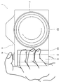
- FIGS. 5 and 6 are a front view and a top view, respectively, showing the grip state of the digital camera during handheld shooting.
- the direction along the optical axis L is the front-rear direction
- the subject side is the front direction.
- the direction along the long side of the image sensor 70 is the horizontal direction or the left-right direction
- the direction along the short side of the image sensor 70 is the vertical direction or vertical direction.
- the digital camera 1 of the present embodiment is a lens-interchangeable medium format digital camera and a non-reflex digital camera.
- the lens interchangeable type is a digital camera that can exchange lenses.
- the medium format digital camera is a digital camera using a medium format image sensor as an image sensor.
- the medium size is a size corresponding to a brownie film.
- the medium size image sensor has a larger screen size than the 35 mm full size image sensor.
- the screen size of a 35 mm full-size image sensor is about 24 mm ⁇ 36 mm (vertical ⁇ horizontal).
- an image sensor having a screen size (sensor size) of about 33 mm ⁇ 40 mm (vertical ⁇ horizontal) is used as an image sensor corresponding to 6 ⁇ 4.5 size.
- the non-reflex type is a digital camera that does not have a reflex mirror for guiding incident light from a lens to an optical viewfinder.
- the digital camera 1 includes a camera body 10 to which a lens can be attached.
- 1 to 4 show a state where the lens 2 is removed
- FIGS. 5 and 6 show a state where the lens 2 is attached.
- the camera body 10 includes a lens mount 14 for mounting the lens 2, a main display 16, a sub display 18, an electronic viewfinder 20, various operation buttons, a battery cover 40, and the like.
- the camera body 10 includes a main body 10A and an overhang 10B, and has a horizontally long shape as shown in FIG. 1 in a front view.
- the bottom surface of the camera body 10 is parallel to the long side of the image sensor 70.
- the main body 10A has a rounded rectangular parallelepiped box shape as a whole.
- the overhanging part 10B is provided on one side of the main body part 10A, and has a shape in which a part of the main body part 10A overhangs in the lateral direction.
- the overhanging portion 10B is thinner than the main body portion 10A, and functions as a grip region during handheld shooting.
- the end portion of the overhang portion 10B is configured as a grip portion 12.
- the grip portion 12 is a portion that the user grips during hand-held shooting.
- the grip portion 12 is configured to be thinner than the main body portion 10A.
- the grip unit 12 is provided with a grip 22 on the front side of the camera body 10.
- the grip 22 is configured as a protrusion that protrudes in a trapezoidal shape toward the front. As shown in FIGS. 5 and 6, when hand-held shooting is performed, the user grips the camera body 10 using the grip 22 as a finger grip.
- the grip portion 12 is provided with a thumb rest 24 on the back side of the camera body 10.
- the thumb rest 24 is configured as a protrusion that protrudes rearward. As shown in FIGS. 5 and 6, when hand-held shooting is performed, the user puts his thumb on the thumb rest 24 and grips the camera body 10.
- the lens mount 14 is a lens mounting portion. As shown in FIG. 1, the lens mount 14 is provided in front of the camera body 10. The lens mount 14 is disposed substantially at the center of the main body 10 ⁇ / b> A of the camera main body 10.
- the main display 16 is a large screen display for displaying images and the like, and is provided on the back surface of the camera body 10 as shown in FIG.
- the main display 16 is disposed approximately at the center of the main body 10 ⁇ / b> A of the camera body 10.
- the main display 16 is composed of a color LCD (LCD: Liquid Crystal Display).
- the sub display 18 is a small screen display for displaying the setting contents of the camera.
- the sub display 18 is provided on the upper surface (top surface) of the camera body 10.
- the sub display 18 is provided in the overhanging portion 10 ⁇ / b> B of the camera body 10.
- the sub display 18 is constituted by, for example, a reflective LCD provided with illumination.
- the electronic viewfinder 20 is provided in the main body 10A of the camera main body 10 and is disposed on the upper surface of the main body 10A.
- the electronic viewfinder 20 has an eyepiece 20 ⁇ / b> A on the back side of the camera body 10.
- the camera body 10 is provided with various operation buttons for operating the digital camera 1.
- the shutter button 30 is an operation member that instructs execution of shooting.
- the shutter button 30 is composed of a two-stage switch composed of a so-called half press and a full press. When the shutter button 30 is half-pressed, photometry, distance measurement, and the like are performed, and when the shutter button 30 is fully pressed, actual photographing is performed.
- the shutter button 30 is disposed at a position where it can be operated with an index finger when the camera body 10 is gripped. In the digital camera 1 of the present embodiment, a shutter button 30 is disposed on the upper surface of the camera body 10.
- buttons include a power lever for turning on / off the digital camera 1, a menu button for calling a menu screen, a cross button, an OK button, a cancel button, a play button, a delete button, a command dial, and the like.
- the battery cover 40 is a lid for opening and closing the battery insertion opening 90 ⁇ / b> A of the battery chamber 90.
- the battery chamber 90 will be described later.
- the battery cover 40 is provided on the end surface (the right side surface in FIG. 1) of the main body 10A. That is, it is provided on the end surface opposite to the grip portion 12.
- FIG. 7 is a top perspective view showing a schematic configuration inside the digital camera.
- the digital camera 1 includes an image sensor 70, a main board 80, a battery chamber 90, a display unit 100, a focal plane shutter unit 110, and the like inside the camera body 10.
- the image sensor 70 is disposed on the optical axis. As described above, a medium format image sensor is used as the image sensor 70. In the digital camera 1 of the present embodiment, a color image sensor having a screen size of about 33 mm ⁇ 40 mm (vertical ⁇ horizontal) is used.
- the image sensor 70 may be a known image sensor such as a CCD image sensor (CCD: “Charged” Coupled Device) or a CMOS image sensor (CMOS: Complementary “Metal” Oxide “Semiconductor”).
- CCD Charged” Coupled Device
- CMOS Complementary “Metal” Oxide “Semiconductor”.
- the main board 80 is a main board of the digital camera 1, and various electronic components are mounted thereon.
- the main board 80 is disposed between the image sensor 70 and the display unit 100. Detailed arrangement will be described later.
- FIG. 8 is a front perspective view showing the arrangement structure of the battery chamber.
- the battery chamber 90 is a housing part for the battery 92.
- the battery 92 of the digital camera 1 according to the present embodiment has a rectangular parallelepiped shape.
- the battery chamber 90 has a rectangular parallelepiped box shape corresponding to the shape of the battery 92.
- the battery chamber 90 is disposed between the image sensor 70 and the display unit 100 and is disposed at the end opposite to the grip portion 12.
- the battery 92 is loaded into the battery chamber 90 from the battery insertion port 90A.
- the battery insertion port 90 ⁇ / b> A is provided on the end surface of the end portion on the opposite side of the end portion having the grip portion 12 of the camera body 10.
- the battery insertion opening 90A is provided with a battery cover 40 that can be opened and closed.
- the battery 92 is inserted laterally from the battery insertion opening 90 ⁇ / b> A and loaded into the battery chamber 90.
- the main board 80 is provided with a notch 82 corresponding to the position where the battery chamber 90 is arranged.
- the battery chamber 90 is disposed so as to be accommodated in the notch 82.
- the display unit 100 is a unit constituting the main display 16. As described above, the display unit 100 is composed of a color LCD. The display unit 100 is disposed on the back surface of the main body 10 ⁇ / b> A of the camera body 10.
- the focal plane shutter unit 110 is a unit that constitutes a mechanical shutter of the digital camera 1.
- the focal plane shutter unit 110 is a square type, and a shutter curtain is constituted by a plurality of shutter blades.
- the focal plane shutter unit 110 is disposed immediately before the image sensor 70. Detailed arrangement will be described later.
- FIG. 9 is a front view showing a schematic configuration of the focal plane shutter unit. The figure shows a state where the front curtain is closed and the rear curtain is opened.
- the focal plane shutter unit 110 includes a base plate 114 having an exposure opening 112, a shutter curtain 116 that opens and closes the exposure opening 112 of the base plate 114, and a drive unit 120 that drives the shutter curtain 116 to open and close.
- the ground plane 114 has a rectangular flat plate shape.
- the exposure opening 112 is provided in the base plate 114 as a rectangular opening.
- the exposure opening 112 is provided at the right end of the base plate 114 when viewed from the front.
- the size of the exposure opening 112 is a size corresponding to the screen size of the image sensor 70.
- the shutter curtain 116 includes a front curtain 116A and a rear curtain 116B.
- Each of the front curtain 116A and the rear curtain 116B includes four shutter blades 116a and 116b.
- the shutter blades 116a constituting the front curtain 116A are attached to a front curtain drive arm (not shown). By rotating (swinging) the front curtain drive arm, the shutter blades 116a move in parallel to open and close the exposure opening 112.
- FIG. 9 shows a state in which the front curtain 116A is closed.
- the shutter blades 116a are folded so as to overlap each other, and the exposure opening 112 is opened.
- the shutter blades 116a are expanded so as to be widened, and the exposure opening 112 is closed.
- Each shutter blade 116b constituting the rear curtain 116B is attached to the rear curtain drive arm 118B. By rotating (swinging) the rear curtain drive arm 118B, the shutter blades 116b move in parallel with each other to open and close the exposure opening 112. .
- FIG. 9 shows a state in which the rear curtain 116B is opened.
- the shutter blade 116b is expanded so that the interval between the shutter blades 116b is widened, and the exposure opening 112 is closed.
- the shutter blades 116b are folded so as to overlap each other, and the exposure opening 112 is opened.
- the driving unit 120 includes a driving unit 122 that opens and closes the shutter curtain 116 and a charging unit 124 that charges the driving force of the driving unit 122.
- the drive unit 120 is provided at one end of the base plate 114, that is, at the end opposite to the exposure opening 112.
- the drive unit 122 includes a front curtain drive shaft 124A that is a drive shaft of the front curtain 116A, a rear curtain drive shaft 124B that is a drive shaft of the rear curtain 116B, a front curtain drive lever 126A that rotationally drives the front curtain drive arm, A rear curtain drive lever 126B that rotationally drives the rear curtain drive arm 118B, a front curtain biasing spring 128A that biases the front curtain drive lever 126A, a rear curtain biasing spring 128B that biases the rear curtain drive lever 126B, A front-curtain electromagnet 130A that holds the front-curtain drive lever 126A, a rear-curtain electromagnet 130B that holds the rear-curtain drive lever 126B, a front-curtain cushioning member (not shown) that cushions an impact when the front-curtain 116A stops, and a rear-curtain 116B And a rear curtain cushioning member (not shown) that
- the front curtain drive shaft 124A is a drive shaft of the front curtain 116A, and is the rotation center of each shutter blade 116a constituting the front curtain 116A.
- the front curtain drive arm to which each shutter blade 116a is attached is rotatable about the front curtain drive shaft 124A.
- the rear curtain drive shaft 124B is a drive shaft of the rear curtain 116B, and is the rotation center of each shutter blade 116b constituting the rear curtain 116B.
- the rear curtain drive arm 118B, to which each shutter blade 116b is attached, is rotatable about the rear curtain drive shaft 124B.
- the front curtain drive lever 126A is a member that rotationally drives the front curtain drive arm.
- the front curtain drive lever 126A is rotatably supported by the front curtain drive shaft 124A.
- the front curtain drive lever 126A has a front curtain drive pin 126a, and is connected to the front curtain drive arm via the front curtain drive pin 126a.
- the front curtain drive lever 126A rotates about the front curtain drive shaft 124A, the rotation is transmitted to the front curtain drive arm via the front curtain drive pin 126a, and the front curtain drive arm rotates about the front curtain drive shaft 124A. To do.
- the rear curtain drive lever 126B is a member that rotationally drives the rear curtain drive arm 118B.
- the rear curtain drive lever 126B is rotatably supported by the rear curtain drive shaft 124B.
- the rear curtain drive lever 126B has a rear curtain drive pin 126b, and is connected to the rear curtain drive arm 118B via the rear curtain drive pin 126b.
- the rotation is transmitted to the rear curtain drive arm 118B via the rear curtain drive pin 126b, and the rear curtain drive arm 118B centers on the rear curtain drive shaft 124B. Rotate to.
- the front curtain biasing spring 128A is a member that biases the front curtain drive lever 126A and biases the front curtain 116A in the direction of opening.
- the opening direction of the front curtain 116A is a clockwise direction around the front curtain drive shaft 124A in FIG.
- the front curtain biasing spring 128A is constituted by a torsion bar spring.
- the front curtain biasing spring 128A is attached to the front curtain drive shaft 124A with the front curtain drive shaft 124A fitted into the inner periphery thereof.
- the front curtain biasing spring 128A has one end hooked on a spring receiver 132A provided on the base plate 114, and the other end hooked on a spring receiver 134A provided on the front curtain drive lever 126A. Energize around.
- the rear curtain biasing spring 128B is a member that biases the rear curtain drive lever 126B, and biases the rear curtain 116B in the closing direction.
- the closing direction of the rear curtain 116B is a clockwise direction around the rear curtain drive shaft 124B in FIG.
- the rear curtain biasing spring 128B is configured by a torsion bar spring.
- the rear curtain urging spring 128B is attached to the rear curtain drive shaft 124B with the rear curtain drive shaft 124B fitted into the inner periphery thereof.
- the rear curtain biasing spring 128B has one end hooked on a spring receiver 132B provided on the base plate 114, and the other end hooked on a spring receiver 134B provided on the rear curtain drive lever 126B. Energize around.
- the front curtain electromagnet 130A is a member that holds the front curtain drive lever 126A, and holds the front curtain 116A in a closed state. That is, it holds in a charged state.
- the front curtain electromagnet 130A is provided on the ground plane 114.
- the front curtain drive lever 126A is provided with a magnetic piece 136A held by the front curtain electromagnet 130A.
- the magnetic piece 136A contacts the front curtain electromagnet 130A. Accordingly, the magnetic piece 136A can be held by the front curtain electromagnet 130A, and the front curtain 116A can be held in a closed state.
- the rear curtain electromagnet 130B is a member that holds the rear curtain drive lever 126B, and holds the rear curtain 116B in an opened state. That is, it holds in a charged state.
- the rear curtain electromagnet 130B is provided on the base plate 114.
- the rear curtain drive lever 126B is provided with a magnetic piece 136B held by the rear curtain electromagnet 130B.
- the magnetic piece 136B contacts the rear curtain electromagnet 130B.
- the magnetic piece 136B can be held by the rear curtain electromagnet 130B, and the rear curtain 116B can be held open.
- the front curtain cushioning member cushions the impact when the front curtain 116A stops.
- the front curtain buffer member is provided on the base plate 114. The front curtain buffer member abuts on the front curtain drive pin at the end of travel of the front curtain 116A, and cushions an impact when the front curtain 116A is stopped.
- the trailing curtain cushioning member cushions the impact when the trailing curtain 116B stops.
- the rear curtain buffer member is provided on the base plate 114. The rear curtain cushioning member abuts on the rear curtain drive pin at the end of travel of the rear curtain 116B, and cushions an impact when the rear curtain 116B is stopped.
- the charging unit 124 charges the driving force of the driving unit 122. That is, the front curtain 116A and the rear curtain 116B are wound up against the biasing force of the front curtain biasing spring 128A and the rear curtain biasing spring 128B.
- the charging unit 124 is disposed adjacent to the driving unit 122.
- the drive unit 122 and the charge unit 124 are arranged in parallel, and the charge unit 124 is arranged outside the drive unit 122.
- the outside of the drive unit 122 means the opposite side of the exposure opening 112 with the drive unit 122 as a reference.
- the charging unit 124 includes a charge lever 140 that charges the front curtain 116A and the rear curtain 116B, a charge motor 142, and a rotation transmission mechanism 144 that transmits the rotation of the charge motor 142 to the charge lever 140.
- the charge lever 140 has a structure in which a front curtain charge lever 140A that charges the front curtain 116A, a rear curtain charge lever 140B that charges the rear curtain 116B, a charge gear 140C, and a rotary shaft 140D are integrated.
- the front curtain charge lever 140A, the rear curtain charge lever 140B, the charge gear 140C, and the rotating shaft 140D are arranged coaxially.
- the charge lever 140 is rotatably supported by the main plate 114 with a rotation shaft 140D supported by a bearing (not shown) provided on the main plate 114.
- the rotation direction of the charge lever 140 is a clockwise direction in FIG.
- the front curtain charge lever 140A rotates to contact the front curtain drive lever 126A and rotate the front curtain drive lever 126A.
- the front curtain drive lever 126A is provided with a roller 146A coaxially with the spring receiver 134A. When the front curtain charge lever 140A rotates, the front curtain charge lever 140A comes into contact with the roller 146A and rotates the front curtain drive lever 126A.
- the rear curtain charge lever 140B rotates to come into contact with the rear curtain drive lever 126B and rotate the rear curtain drive lever 126B.
- the rear curtain drive lever 126B is provided with a roller 146B coaxially with the spring receiver 134B. When the trailing curtain charge lever 140B rotates, the trailing curtain charge lever 140B comes into contact with the roller 146B and rotates the trailing curtain drive lever 126B.
- the charge motor 142 is provided on the main plate 114.
- the charge motor 142 has a drive gear 148 on its output shaft.
- the rotation transmission mechanism 144 includes a gear train and transmits rotation between the drive gear 148 and the charge gear 140C.
- the front curtain charge lever 140A When the charge lever 140 rotates, the front curtain charge lever 140A first contacts the roller 146A of the front curtain drive lever 126A to rotate the front curtain drive lever 126A. At this time, the front curtain drive lever 126A rotates counterclockwise in FIG. The front curtain drive lever 126A rotates against the biasing force of the front curtain biasing spring 128A.
- the front curtain drive lever 126A rotates, the front curtain drive arm also rotates. As a result, the front curtain 116A is closed.
- the magnetic piece 136A provided on the front curtain drive lever 126A comes into contact with the front curtain electromagnet 130A.
- the front curtain electromagnet 130A is driven in accordance with the timing of this contact, and the magnetic piece 136A is held by the front curtain electromagnet 130A. Thereby, the charging of the leading curtain 116A is completed.
- the rear curtain charge lever 140B contacts the roller 146B of the rear curtain drive lever 126B, and rotates the rear curtain drive lever 126B.
- the trailing curtain drive lever 126B rotates counterclockwise in FIG.
- the rear curtain drive lever 126B rotates against the biasing force of the rear curtain biasing spring 128B.
- the rear curtain drive lever 126B rotates, the rear curtain drive arm 118B also rotates. As a result, the rear curtain 116B is opened.
- the magnetic piece 136B provided on the rear curtain drive lever 126B comes into contact with the rear curtain electromagnet 130B.
- the rear curtain electromagnet 130B is driven in accordance with the timing of this contact, and the magnetic piece 136B is held by the rear curtain electromagnet 130B. Thereby, the charging of the trailing curtain 116B is completed.
- Exposure Exposure is performed by opening the front curtain 116A and then closing the rear curtain 116B.
- the holding of the magnetic piece 136B by the rear curtain electromagnet 130B is released in accordance with the exposure time.
- the rear curtain drive lever 126B is rotated by the biasing force of the rear curtain biasing spring 128B.
- the rear curtain drive arm 118B rotates and the rear curtain 116B is closed.
- the image sensor 70, the main substrate 80, the battery chamber 90, the display unit 100, and the focal plane shutter unit 110 are disposed inside the camera body 10.
- the image sensor 70 is disposed on the optical axis L in the camera body. That is, it is arranged so that the center of the light receiving surface is located on the optical axis L. Further, the light receiving surface is disposed so as to be orthogonal to the optical axis L.
- the display unit 100 is also arranged almost on the optical axis L. As described above, the display unit 100 constitutes the main display 16 and is disposed on the back surface of the camera body 10. Since the arrangement position of the main display 16 is the main body 10A of the camera body 10, the arrangement position of the display unit 100 is also the main body 10A of the camera body 10.
- the main board 80 is disposed between the image sensor 70 and the display unit 100.
- the main substrate 80 is disposed orthogonal to the optical axis L.
- the battery chamber 90 is also disposed between the image sensor 70 and the display unit 100.
- the battery chamber 90 is disposed close to the end of the camera body 10.
- the end portion is an end portion on the opposite side to the grip portion 12.
- the battery 92 which is a heavy object is arrange
- the battery chamber 90 is disposed rearward relative to the focal plane shutter unit 110. Thereby, the dimension of the horizontal direction of the camera main body 10 can be made compact.
- the main board 80 is provided with a notch 82 corresponding to the arrangement position of the battery chamber 90.
- the battery chamber 90 is disposed so as to be accommodated in the notch 82.
- the focal plane shutter unit 110 is disposed immediately before the image sensor 70.
- the focal plane shutter unit 110 is arranged so that the ground plane 114 is orthogonal to the optical axis L. Further, the exposure opening 112 is arranged so that the center thereof is located on the optical axis L.
- FIG. 10 is a front perspective view showing the arrangement structure of the focal plane shutter unit.
- the focal plane shutter unit 110 has a charging portion 124 disposed within the range GA of the grip portion 12.
- the charging unit 124 is disposed in the grip unit.
- the drive unit 122 and the charge unit 124 of the focal plane shutter unit 110 are arranged in parallel. Thereby, the drive unit 120 of the focal plane shutter unit can be made compact and can be operated stably even when charging with a large torque.
- the charging unit 124 of the focal plane shutter unit 110 is disposed in the grip unit 12.
- the vicinity of the center of rotation of the shutter curtain 116 can be gripped, and vibration during shutter operation can be effectively suppressed. That is, the main cause of the vibration generated when the shutter is operated is the moment received when the shutter curtain 116 is braked. This moment is generated around the rotation center of the shutter curtain 116.
- the influence of the moment can be suppressed, and the occurrence of vibration can be effectively suppressed.
- the heavy battery 92 is disposed at the end opposite to the grip portion 12. Thereby, the inertia moment centering on the grip part 12 can be enlarged, and generation
- the vibration generated due to the shutter operation is generated around the drive axis of the shutter curtain 116, the vibration caused by the shutter operation is suppressed by increasing the rotation moment about the drive axis of the shutter curtain 116. Can increase the moment of inertia in the direction. As a result, vibration generated due to the shutter operation can be hardly transmitted to the camera body. Thereby, generation
- the battery 92 is arranged between the image sensor 70 and the display unit 100, so that the lateral dimension of the camera body 10 can be reduced.
- the camera body 10 is thicker, but by making the grip portion 12 thinner than the main body portion 10A, it is possible to ensure good grip properties.
- the battery cover 40 on the side of the camera body 10 and loading the battery 92 into the battery chamber 90 from the side, the battery 92 can be easily replaced.
- the present invention works particularly effectively when applied to a reflex type digital camera.
- a reflex type digital camera In the case of a non-reflex type digital camera, there is no mirror box, pentaprism, etc., so the whole is light.
- the vibration during shutter operation becomes more prominent as the camera becomes lighter.
- the present invention that can effectively suppress vibration during shutter operation works particularly effectively in a non-reflex digital camera.
- ⁇ Focal plane shutter unit> the case where the front curtain and the rear curtain constituting the shutter curtain are configured by four shutter blades has been described as an example.
- the number of the shutter blades constituting the front curtain and the rear curtain is not limited thereto. It is not limited. It can be appropriately increased or decreased according to the size of the exposure opening.
- the drive unit and the charge unit can be unitized and assembled to the main plate.
- the shape of the battery is a rectangular parallelepiped shape, but the shape of the battery is not limited to this. It can also be a plate shape or a cylindrical shape.
- one battery is loaded in the camera body, but a plurality of batteries may be loaded.
Landscapes
- Physics & Mathematics (AREA)
- General Physics & Mathematics (AREA)
- Engineering & Computer Science (AREA)
- Multimedia (AREA)
- Signal Processing (AREA)
- Studio Devices (AREA)
- Shutters For Cameras (AREA)
- Camera Bodies And Camera Details Or Accessories (AREA)
Abstract
Provided is a digital camera in which a stable shutter action is possible with a compact structure, said digital camera also being able to suppress the occurrence of vibration that accompanies the actuation of a shutter. A grip part (22) is provided to an end section on one side of a camera body (10), and a charge part (124) of a focal-plane shutter unit (110) is positioned within a range GA of this grip part (22). Additionally, a battery is positioned in an end section on the opposite side from the grip part (22), between an image sensor and a display unit. By positioning the charge part within the range of the grip part, the charge part (124) and a drive part (122) can be positioned close together. A drive unit of the focal-plane shutter can thus be made compact, and can be charged with a stable action, even when charging with a large torque. Additionally, during handheld photography, the vicinity of a rotational center of a shutter curtain can be gripped with the hand, and the occurrence of vibration can be effectively suppressed.
Description
本発明は、デジタルカメラに係り、特にスクエア型のフォーカルプレーンシャッターを備えたデジタルカメラに関する。
The present invention relates to a digital camera, and more particularly to a digital camera provided with a square-type focal plane shutter.
レンズ交換式のカメラの多くは、シャッターにフォーカルプレーンシャッターを採用している。フォーカルプレーンシャッターとは、焦点面の直前に設置されるシャッターのことである。フォーカルプレーンシャッターは、先幕と後幕の2枚のシャッター幕を備え、その2枚のシャッター幕の間隔(スリット)と走行速度の変化によって露出時間を制御する。
多 く Many interchangeable lens cameras employ a focal plane shutter. The focal plane shutter is a shutter installed immediately before the focal plane. The focal plane shutter has two shutter curtains, a front curtain and a rear curtain, and the exposure time is controlled by changing the distance (slit) between the two shutter curtains and the running speed.
フォーカルプレーンシャッターは、その機構によりドラム型、スクエア型、ロータリー型の3つに大別できる。現在はスクエア型が主流である。
¡Focal plane shutters can be roughly classified into three types: drum type, square type, and rotary type. Currently, the square type is the mainstream.
スクエア型は、薄板状のシャッター羽根を複数並べてシャッター幕とする方式である。閉じているときは、シャッター羽根の間隔を広げて露光開口を遮光し、開いているときは、シャッター羽根同士が重なることで畳まれて露光開口外の領域に退避する。シャッター幕を構成するシャッター羽根は、アーム部材に支持されており、アーム部材が回転することによって、互いに平行に移動する。スクエア型は、シャッター幕が上下方向に走行して露光開口を開閉することから、上下走行方式、縦走り方式などとも称される。また、シャッター幕を構成するシャッター羽根の形状からブレード式などとも称される。
The square type is a method in which a plurality of thin shutter blades are arranged to form a shutter curtain. When it is closed, the interval between the shutter blades is widened to shield the exposure opening, and when it is open, the shutter blades are folded together and retracted to an area outside the exposure opening. The shutter blades constituting the shutter curtain are supported by the arm member, and move in parallel with each other as the arm member rotates. The square type is also referred to as a vertical traveling method, a vertical traveling method, etc., because the shutter curtain travels in the vertical direction to open and close the exposure opening. Further, it is also called a blade type because of the shape of the shutter blades constituting the shutter curtain.
特許文献1には、スクエア型のフォーカルプレーンシャッターを備えたカメラにおいて、全体のコンパクト化を図るために、カメラ本体とグリップ部と結合部分にフォーカルプレーンシャッターの駆動ユニットを配置することが提案されている。
Patent Document 1 proposes to arrange a focal plane shutter drive unit in the camera body, the grip portion, and the coupling portion in order to reduce the overall size of the camera having a square type focal plane shutter. Yes.
また、特許文献2には、スクエア型のフォーカルプレーンシャッターを備えたデジタルカメラにおいて、全体のコンパクト化を図るために、フォーカルプレーンシャッターの駆動機構部をシャッター羽根の作動面より撮像素子側に配置することが提案されている。
In Patent Document 2, in a digital camera equipped with a square-type focal plane shutter, the focal plane shutter drive mechanism is disposed closer to the image sensor than the operating surface of the shutter blade in order to reduce the overall size. It has been proposed.
また、特許文献3には、スクエア型のフォーカルプレーンシャッターを備えたデジタルカメラにおいて、全体のコンパクト化を図るために、フォーカルプレーンシャッターの駆動機構部をグリップ部とは反対側の領域に配置することが提案されている。
Patent Document 3 discloses that in a digital camera equipped with a square-type focal plane shutter, the focal plane shutter drive mechanism is disposed in a region opposite to the grip portion in order to reduce the overall size. Has been proposed.
フォーカルプレーンシャッターを使用したカメラは、シャッター作動時に振動が発生しやすいという問題がある(いわゆるシャッターショック)。そして、この問題は、イメージセンサーのサイズが大きくなるほど顕著となる。また、カメラが軽量になるほど顕著となる。
¡Cameras using a focal plane shutter have a problem that vibration is likely to occur when the shutter is operated (so-called shutter shock). This problem becomes more prominent as the size of the image sensor increases. In addition, it becomes more prominent as the camera becomes lighter.
特許文献1から3に記載のカメラは、シャッター作動時の振動への対策がなされておらず、カメラ振れが生じやすいという欠点がある。この点について、更に詳しく説明する。カメラ振れについては、シャッター動作に起因するものを除くと、その多くが手振れに起因して発生する。手振れによる振動は、1~15Hz程度の低い周波数の振動である。この種の低い周波数の振動は、一般的な手振れ補正技術を用いれば、数分の一程度にまで低減できる。
The cameras described in Patent Documents 1 to 3 have a drawback in that camera shake is likely to occur because no measures are taken against vibration during shutter operation. This point will be described in more detail. Many camera shakes are caused by camera shake except those caused by the shutter operation. Vibration due to hand shake is vibration with a low frequency of about 1 to 15 Hz. This type of low frequency vibration can be reduced to a fraction of a fraction using a general image stabilization technique.
しかし、シャッター動作に起因して発生する振動は、高速で走行するシャッター羽根を瞬時に停止させることの反力によって発生するものであるため、その振動の周波数は、手振れに起因して発生する振動の周波数よりもはるかに高いものとなる。したがって、手振れの周波数領域の補正に最適化された技術を用いても、シャッター動作に起因して発生する振動を大幅に低減させることはできない。
However, since the vibration generated due to the shutter operation is generated by the reaction force of instantaneously stopping the shutter blade that travels at high speed, the frequency of the vibration is the vibration generated due to camera shake. Much higher than the frequency of. Therefore, even if a technique optimized for correcting the frequency region of camera shake is used, the vibration generated due to the shutter operation cannot be significantly reduced.
特に、中判カメラは、35ミリ判カメラよりも大きな露出開口を有するため、フォーカルプレーンシャッターを使用すると、シャッター動作に起因して発生する振動が顕著になる。すなわち、露光開口が大きくなると、シャッター羽根の走行距離も長くなり、その分、シャッター羽根の走行エネルギーも大きくなる(走行距離の二乗に比例して走行エネルギーが大きくなる)。その結果、停止時に発生する反力が大きくなり、そのままでは無視できないレベルの振動が発生する。
Especially, since a medium format camera has a larger exposure opening than a 35 mm format camera, when a focal plane shutter is used, vibration generated due to the shutter operation becomes remarkable. That is, when the exposure aperture is increased, the travel distance of the shutter blades is increased, and the travel energy of the shutter blades is correspondingly increased (the travel energy is increased in proportion to the square of the travel distance). As a result, the reaction force generated at the time of stoppage becomes large, and vibration of a level that cannot be ignored as it is is generated.
また、近年、デジタルカメラで使用されるイメージセンサーの画素サイズは、銀塩フィルムの銀塩粒子のサイズよりもはるかに小さくなっており(おおよそ1/10程度)、同じ画面サイズであっても、カメラ振れの影響は、銀塩カメラよりもデジタルカメラの方が顕著となる。
In recent years, the pixel size of an image sensor used in a digital camera is much smaller than the size of silver salt particles of a silver salt film (about 1/10), and even with the same screen size, The effects of camera shake are more pronounced with digital cameras than with silver halide cameras.
本発明は、このような事情に鑑みてなされたものであり、軽量かつコンパクトな構成で安定したシャッター動作が可能であり、かつ、イメージセンサーのサイズが大きいほど影響が顕著になるシャッター動作に伴う振動のカメラへの伝達を抑制できるデジタルカメラを提供することを目的とする。
The present invention has been made in view of such circumstances, and is capable of a stable shutter operation with a light and compact configuration, and is associated with a shutter operation in which the influence becomes remarkable as the size of the image sensor increases. It is an object of the present invention to provide a digital camera that can suppress transmission of vibration to the camera.
上記課題を解決するための手段は次のとおりである。
Measures for solving the above problems are as follows.
(1)一方側の端部にグリップ部を有するカメラ本体と、カメラ本体の正面に備えられるレンズ又はレンズマウントと、カメラ本体の背面に備えられるディスプレーユニットと、カメラ本体内に備えられるイメージセンサーと、露光開口を有する地板と、露光開口を開閉するシャッター幕と、シャッター幕を開閉駆動する駆動部と、駆動部の駆動力をチャージするチャージ部と、を備え、地板の一方側の端部にチャージ部が配置されたスクエア型のフォーカルプレーンシャッターユニットであって、カメラ本体内においてイメージセンサーの直前に配置され、かつ、チャージ部がグリップ部の範囲内に配置されるフォーカルプレーンシャッターユニットと、カメラ本体内においてイメージセンサーとディスプレーユニットとの間に配置され、かつ、グリップ部を有する端部と反対側の端部に配置されるバッテリーと、を備えたデジタルカメラ。
(1) A camera body having a grip at one end, a lens or lens mount provided on the front of the camera body, a display unit provided on the back of the camera body, and an image sensor provided in the camera body A base plate having an exposure opening, a shutter curtain that opens and closes the exposure opening, a drive unit that drives the shutter curtain to open and close, and a charge unit that charges the driving force of the drive unit, at one end of the base plate A square-type focal plane shutter unit in which a charging unit is disposed, the focal plane shutter unit being disposed in front of the image sensor in the camera body, and the charging unit being disposed in the range of the grip unit, and a camera It is placed between the image sensor and the display unit in the main body. And, a digital camera having a battery disposed at the end opposite to the end having the grip portion.
本態様によれば、カメラ本体の一方側の端部にグリップ部が備えられ、そのグリップ部の範囲内にフォーカルプレーンシャッターユニットのチャージ部が配置される。また、イメージセンサーとディスプレーユニットとの間であって、グリップ部とは反対側の端部にバッテリーが配置される。グリップ部の範囲内にチャージ部を配置することにより、駆動部とチャージ部とを近接して配置できる。これにより、フォーカルプレーンシャッターの駆動ユニットをコンパクト化でき、かつ、大きなトルクでチャージする場合であっても、安定した動作でチャージできる。また、駆動部とチャージ部とを近接して配置できることにより、手持ちによる撮影時にシャッター幕の回転中心付近を手でグリップでき、振動の発生を効果的に抑制できる。すなわち、振動の主な原因は、シャッター幕のブレーキ時に受けるモーメント(シャッター幕の回転中心を中心として受けるモーメント)であるので、シャッター幕の回転中心付近を手でグリップすることにより、振動の発生を効果的に抑制できる。また、グリップ部とは反対側の端部にバッテリーを配置することにより、グリップ部を中心とした慣性モーメントを大きくでき、振動の発生を更に効果的に抑制できる。この点について更に詳しく説明する。本態様によれば、シャッター幕の回転中心をグリップ部に接近させ、更にカメラの回転中心の反対側にバッテリーを配置したレイアウトにできるが、このようなレイアウトを採用することにより、重量物であるバッテリーをシャッター幕の回転中心から遠ざけた位置に配置できる。同じ質量でも質点が回転の中心から離れるほど、その軸の慣性モーメントは大きくなるので、重量物であるバッテリーをシャッター幕の回転中心から遠ざけた位置に配置することにより、シャッター幕の回転軸を中心とした回転モーメント(シャッター幕の回転軸を中心とする光軸と平行な軸周りの回転モーメント)を大きくできる。シャッター動作に起因して発生する振動は、シャッター幕の回転軸を中心に発生するので、シャッター幕の回転軸を中心とした回転モーメントを大きくすることにより、シャッター動作に起因した振動を抑制する方向の慣性モーメントを大きくできる。この結果、シャッター動作に起因して発生する振動をカメラに伝達しにくくでき、カメラ振れの発生を効果的に抑制できる。また、本態様によれば、イメージセンサーとディスプレーユニットとの間にバッテリーを配置することにより、横方向の寸法もコンパクト化できる。
According to this aspect, the grip portion is provided at one end of the camera body, and the charge portion of the focal plane shutter unit is disposed within the range of the grip portion. A battery is disposed between the image sensor and the display unit at the end opposite to the grip portion. By disposing the charge unit within the range of the grip unit, the drive unit and the charge unit can be disposed close to each other. Thereby, the drive unit of the focal plane shutter can be made compact, and charging can be performed with stable operation even when charging with a large torque. In addition, since the driving unit and the charging unit can be disposed close to each other, the vicinity of the rotation center of the shutter curtain can be gripped by hand when shooting by hand, and the occurrence of vibration can be effectively suppressed. In other words, the main cause of vibration is the moment that is received when the shutter curtain is braked (moment received around the rotation center of the shutter curtain). It can be effectively suppressed. Further, by disposing the battery at the end opposite to the grip portion, the moment of inertia around the grip portion can be increased, and the generation of vibration can be further effectively suppressed. This point will be described in more detail. According to this aspect, the layout can be made such that the rotation center of the shutter curtain is brought close to the grip portion, and the battery is arranged on the opposite side of the rotation center of the camera. By adopting such a layout, it is heavy. The battery can be placed away from the center of rotation of the shutter curtain. Even if the mass is the same, the moment of inertia of the axis increases as the mass point moves away from the center of rotation.Therefore, by placing the heavy battery away from the center of rotation of the shutter curtain, the axis of rotation of the shutter curtain is centered. The rotation moment (rotation moment about an axis parallel to the optical axis centered on the rotation axis of the shutter curtain) can be increased. The vibration generated due to the shutter operation is generated around the rotation axis of the shutter curtain, so the direction of suppressing the vibration caused by the shutter operation is increased by increasing the rotational moment around the rotation axis of the shutter curtain. The moment of inertia can be increased. As a result, it is difficult to transmit the vibration generated due to the shutter operation to the camera, and the occurrence of camera shake can be effectively suppressed. Moreover, according to this aspect, by arranging the battery between the image sensor and the display unit, it is possible to reduce the size in the lateral direction.
(2)カメラ本体は、グリップ部よりも厚い厚さの本体部を有し、本体部の正面にレンズ又はレンズマウントが配置され、本体部の背面にディスプレーユニットが配置され、本体部の範囲内にイメージセンサー及びバッテリーが配置される、上記(1)のデジタルカメラ。
(2) The camera body has a body portion thicker than the grip portion, a lens or a lens mount is disposed on the front surface of the body portion, a display unit is disposed on the back surface of the body portion, and is within the range of the body portion. The digital camera according to (1) above, wherein an image sensor and a battery are disposed on the digital camera.
本態様によれば、カメラ本体にグリップ部の厚さよりも厚い本体部が備えられる。そして、その本体部にレンズ又はレンズマウント、ディスプレーユニット、イメージセンサー及びバッテリーが備えられる。これにより、全体をコンパクト化しつつグリップ性を向上できる。
According to this aspect, the camera body is provided with a body portion that is thicker than the grip portion. The main body includes a lens or lens mount, a display unit, an image sensor, and a battery. Thereby, grip property can be improved, making the whole compact.
(3)フォーカルプレーンシャッターユニットは、チャージ部と駆動部とが並列して配置される、上記(1)又は(2)のデジタルカメラ。
(3) The digital camera according to (1) or (2) above, wherein the focal plane shutter unit has a charging unit and a driving unit arranged in parallel.
本態様によれば、チャージ部と駆動部とが並列して配置される。これにより、チャージ部と駆動部とをより近接させて配置できる。この場合、露光開口とチャージ部との間に駆動部が配置される。
According to this aspect, the charging unit and the driving unit are arranged in parallel. Thereby, a charge part and a drive part can be arranged closer. In this case, a driving unit is disposed between the exposure opening and the charging unit.
(4)カメラ本体内にバッテリーを収容するバッテリー室を備え、バッテリー室にバッテリーが収容される、上記(1)から(3)のいずれか1のデジタルカメラ。
(4) The digital camera according to any one of (1) to (3) above, wherein the camera body includes a battery chamber for storing a battery, and the battery is stored in the battery chamber.
本態様によれば、カメラ本体内にバッテリー室が備えられる。これにより、バッテリーを着脱可能に装填できる。
According to this aspect, the battery chamber is provided in the camera body. Thereby, the battery can be detachably loaded.
(5)カメラ本体は、グリップ部を有する端部と反対側の端部の端面にバッテリーをバッテリー室に装填するためのバッテリー挿入口を有する、上記(4)のデジタルカメラ。
(5) The digital camera according to (4), wherein the camera body has a battery insertion port for loading a battery into the battery chamber on an end surface opposite to the end portion having the grip portion.
本態様によれば、グリップ部とは反対側の端部の端面にバッテリーをバッテリー室に装填するためのバッテリー挿入口が備えられる。これにより、バッテリーの着脱を容易にできる。
According to this aspect, the battery insertion port for loading the battery into the battery chamber is provided on the end surface opposite to the grip portion. Thereby, the battery can be easily attached and detached.
(6)カメラ本体は、グリップ部を有する端部と反対側の端部の端面にバッテリー室を開閉する蓋部を有する、上記(4)又は(5)のデジタルカメラ。
(6) The digital camera according to the above (4) or (5), wherein the camera body has a lid portion for opening and closing the battery chamber on the end surface opposite to the end portion having the grip portion.
本態様によれば、グリップ部とは反対側の端部の端面にバッテリー室を開閉する蓋部が備えられる。これにより、バッテリーの着脱を容易にできる。
According to this aspect, the lid that opens and closes the battery chamber is provided on the end surface of the end opposite to the grip. Thereby, the battery can be easily attached and detached.
(7)電子部品が実装された基板を更に備え、基板は、カメラ本体内においてイメージセンサーとディスプレーユニットとの間に配置され、かつ、バッテリーの配置位置に切欠き部を有する、上記(1)から(6)のいずれか1のデジタルカメラ。
(7) The above-described (1), further including a substrate on which electronic components are mounted, the substrate being disposed between the image sensor and the display unit in the camera body, and having a notch at the position where the battery is disposed. To (6) any one of the digital cameras.
本態様によれば、イメージセンサーとディスプレーユニットとの間に配置される基板に切欠き部が備えられ、その切欠き部にバッテリーが配置される。
According to this aspect, the substrate disposed between the image sensor and the display unit is provided with the notch, and the battery is disposed in the notch.
(8)フォーカルプレーンシャッターユニットは、チャージ部がグリップ部内に配置される、上記(1)から(7)のいずれか1のデジタルカメラ。
(8) The digital camera according to any one of (1) to (7) above, wherein the focal plane shutter unit has a charge portion disposed in the grip portion.
本態様によれば、チャージ部がグリップ部内に配置される。グリップ部は、カメラ本体の一方側の端部に備えられるので、このグリップ部内にチャージ部を配置することにより、横方向の寸法をコンパクト化できる。
According to this aspect, the charge part is arranged in the grip part. Since the grip part is provided at one end of the camera body, the lateral dimension can be made compact by disposing the charge part in the grip part.
(9)イメージセンサーは、35ミリ判フルサイズのイメージセンサーよりも大きなセンサーサイズを有する、上記(1)から(8)のいずれか1のデジタルカメラ。
(9) The digital camera according to any one of (1) to (8) above, wherein the image sensor has a larger sensor size than a 35 mm full-size image sensor.
本態様によれば、35ミリ判フルサイズのイメージセンサーよりも大きなセンサーサイズのイメージセンサーが備えられる。シャッター作動時に発生する振動は、センサーサイズが大きくなるほど大きくなるので、イメージセンサーのサイズが大きくなるほど、本発明は有効に作用する。
According to this aspect, an image sensor having a sensor size larger than that of a 35 mm full-size image sensor is provided. Since the vibration generated when the shutter is activated increases as the sensor size increases, the present invention works more effectively as the size of the image sensor increases.
なお、35ミリ判フルサイズのイメージセンサーとは、135フィルム(35mmフィルム)に対応したサイズのイメージセンサーのことである。約24mm×36mm(縦×横)の画面サイズを有する。
The 35 mm full-size image sensor is an image sensor of a size corresponding to 135 film (35 mm film). It has a screen size of about 24 mm × 36 mm (vertical × horizontal).
(10)中判サイズのイメージセンサーである、上記(9)のデジタルカメラ。
(10) The digital camera according to (9), which is a medium format image sensor.
本態様によれば、イメージセンサーが中判サイズのイメージセンサーで構成される。なお、中判サイズとは、ブローニーフィルムに対応したサイズのことである。6×4.5判に対応したイメージセンサーの場合、その画面サイズ(センサーサイズ)は、約33mm×40mm(縦×横)である。
に よ According to this aspect, the image sensor is composed of a medium size image sensor. The medium size is a size corresponding to the brownie film. In the case of an image sensor supporting 6 × 4.5 size, the screen size (sensor size) is about 33 mm × 40 mm (vertical × horizontal).
(11)ノンレフレックス型のデジタルカメラである、上記(1)から(10)のいずれか1項に記載のデジタルカメラ。
(11) The digital camera according to any one of (1) to (10), which is a non-reflex digital camera.
本態様によれば、デジタルカメラがノンレフレックス型のデジタルカメラで構成される。ノンレフレックス型のデジタルカメラとは、レンズからの入射光を光学式ファインダーに導くためのレフレックスミラーのないデジタルカメラのことである。ミラーレス式デジタルカメラ、ミラーレス機などとも称される。ノンレフレックス型のデジタルカメラの場合、ミラーボックス、ペンタプリズム等が不要になることから、全体を軽量かつコンパクトにできる。なお、カメラが軽量になるほどシャッター作動時の振動は顕著になるので、カメラが軽量になるほど、本発明は有効に機能する。
According to this aspect, the digital camera is a non-reflex digital camera. A non-reflex digital camera is a digital camera without a reflex mirror for guiding incident light from a lens to an optical viewfinder. Also called mirrorless digital camera, mirrorless machine, etc. In the case of a non-reflex type digital camera, a mirror box, a pentaprism, and the like are not necessary, so that the whole can be made lightweight and compact. In addition, since the vibration at the time of shutter operation becomes more remarkable as the camera becomes lighter, the present invention functions more effectively as the camera becomes lighter.
本発明によれば、軽量かつコンパクトな構成で安定したシャッター動作が可能となる。また、イメージセンサーのサイズが大きいほど影響が顕著になるシャッター動作に伴う振動のカメラへの伝達を抑制できる。
According to the present invention, a stable shutter operation is possible with a lightweight and compact configuration. Further, it is possible to suppress the transmission of vibrations to the camera due to the shutter operation, the effect of which becomes more significant as the size of the image sensor increases.
以下、添付図面に従って本発明を実施するための好ましい形態について詳説する。
Hereinafter, preferred embodiments for carrying out the present invention will be described in detail with reference to the accompanying drawings.
《外観構成》
図1、図2、図3、図4は、それぞれデジタルカメラの外観構成を示す正面図、上面図、背面図、左側面図である。また、図5、図6は、それぞれ手持ち撮影時におけるデジタルカメラのグリップ状態を示す正面図、上面図である。 <Appearance configuration>
1, 2, 3, and 4 are a front view, a top view, a rear view, and a left side view, respectively, showing the external configuration of the digital camera. FIGS. 5 and 6 are a front view and a top view, respectively, showing the grip state of the digital camera during handheld shooting.
なお、本明細書では、光軸Lに沿う方向を前後方向とし、被写体側を前方向とする。また、光軸Lと直交する面において、イメージセンサー70の長辺に沿う方向(図1のx方向)を横方向又は左右方向とし、イメージセンサー70の短辺に沿う方向(図1のy方向)を縦方向又は上下方向とする。
In this specification, the direction along the optical axis L is the front-rear direction, and the subject side is the front direction. Further, on the plane orthogonal to the optical axis L, the direction along the long side of the image sensor 70 (x direction in FIG. 1) is the horizontal direction or the left-right direction, and the direction along the short side of the image sensor 70 (y direction in FIG. 1). ) Is the vertical direction or vertical direction.
本実施の形態のデジタルカメラ1は、レンズ交換式の中判デジタルカメラであり、かつ、ノンレフレックス型のデジタルカメラである。
The digital camera 1 of the present embodiment is a lens-interchangeable medium format digital camera and a non-reflex digital camera.
レンズ交換式とは、レンズを交換できるデジタルカメラのことである。また、中判デジタルカメラとは、イメージセンサーに中判サイズのイメージセンサーを使用したデジタルカメラのことである。中判サイズとは、ブローニーフィルムに対応したサイズのことである。中判サイズのイメージセンサーは、35ミリ判フルサイズのイメージセンサーよりも大きな画面サイズを有する。なお、35ミリ判フルサイズのイメージセンサーの画面サイズは、約24mm×36mm(縦×横)である。本実施の形態のデジタルカメラ1は、6×4.5判に対応したイメージセンサーとして、画面サイズ(センサーサイズ)が約33mm×40mm(縦×横)のイメージセンサーが使用される。
The lens interchangeable type is a digital camera that can exchange lenses. The medium format digital camera is a digital camera using a medium format image sensor as an image sensor. The medium size is a size corresponding to a brownie film. The medium size image sensor has a larger screen size than the 35 mm full size image sensor. The screen size of a 35 mm full-size image sensor is about 24 mm × 36 mm (vertical × horizontal). In the digital camera 1 of the present embodiment, an image sensor having a screen size (sensor size) of about 33 mm × 40 mm (vertical × horizontal) is used as an image sensor corresponding to 6 × 4.5 size.
ノンレフレックス型とは、レンズからの入射光を光学式ファインダーに導くためのレフレックスミラーのないデジタルカメラのことである。
The non-reflex type is a digital camera that does not have a reflex mirror for guiding incident light from a lens to an optical viewfinder.
図1から図4に示すように、デジタルカメラ1は、レンズが装着可能なカメラ本体10を備える。なお、図1から図4は、レンズ2を取り外した状態を示しており、図5及び図6は、レンズ2を取り付けた状態を示している。
As shown in FIGS. 1 to 4, the digital camera 1 includes a camera body 10 to which a lens can be attached. 1 to 4 show a state where the lens 2 is removed, and FIGS. 5 and 6 show a state where the lens 2 is attached.
カメラ本体10には、レンズ2を装着するためのレンズマウント14、メインディスプレー16、サブディスプレー18、電子ビューファインダー20、各種操作ボタン類、バッテリーカバー40等が備えられる。
The camera body 10 includes a lens mount 14 for mounting the lens 2, a main display 16, a sub display 18, an electronic viewfinder 20, various operation buttons, a battery cover 40, and the like.
〈カメラ本体〉
カメラ本体10は、本体部10Aと、張出部10Bとを有し、正面視において、図1に示すように、横長の形状を有する。カメラ本体10の底面は、イメージセンサー70の長辺と平行である。 <Camera body>
Thecamera body 10 includes a main body 10A and an overhang 10B, and has a horizontally long shape as shown in FIG. 1 in a front view. The bottom surface of the camera body 10 is parallel to the long side of the image sensor 70.
カメラ本体10は、本体部10Aと、張出部10Bとを有し、正面視において、図1に示すように、横長の形状を有する。カメラ本体10の底面は、イメージセンサー70の長辺と平行である。 <Camera body>
The
本体部10Aは、全体として丸みを帯びた直方体の箱形状を有する。張出部10Bは、本体部10Aの片側に備えられ、本体部10Aの一部が横方向に張り出した形状を有する。張出部10Bは、本体部10Aよりも薄く、手持ち撮影時のグリップ領域として機能する。
The main body 10A has a rounded rectangular parallelepiped box shape as a whole. The overhanging part 10B is provided on one side of the main body part 10A, and has a shape in which a part of the main body part 10A overhangs in the lateral direction. The overhanging portion 10B is thinner than the main body portion 10A, and functions as a grip region during handheld shooting.
張出部10Bは、その端部がグリップ部12として構成される。グリップ部12は、手持ち撮影時にユーザーがグリップする部分である。グリップ部12は、本体部10Aよりも薄く構成される。
The end portion of the overhang portion 10B is configured as a grip portion 12. The grip portion 12 is a portion that the user grips during hand-held shooting. The grip portion 12 is configured to be thinner than the main body portion 10A.
グリップ部12には、カメラ本体10の正面側にグリップ22が備えられる。グリップ22は、前方に向かって台形状に突出する突出部として構成される。図5、図6に示すように、手持ち撮影する際、ユーザーは、このグリップ22を指掛かりとして、カメラ本体10をグリップする。
The grip unit 12 is provided with a grip 22 on the front side of the camera body 10. The grip 22 is configured as a protrusion that protrudes in a trapezoidal shape toward the front. As shown in FIGS. 5 and 6, when hand-held shooting is performed, the user grips the camera body 10 using the grip 22 as a finger grip.
また、グリップ部12には、カメラ本体10の背面側にサムレスト24が備えられる。サムレスト24は、後方に向かって凸状に突出する突出部として構成される。図5、図6に示すように、手持ち撮影する際、ユーザーは、このサムレスト24に親指を掛けて、カメラ本体10をグリップする。
Further, the grip portion 12 is provided with a thumb rest 24 on the back side of the camera body 10. The thumb rest 24 is configured as a protrusion that protrudes rearward. As shown in FIGS. 5 and 6, when hand-held shooting is performed, the user puts his thumb on the thumb rest 24 and grips the camera body 10.
〈レンズマウント〉
レンズマウント14は、レンズの取り付け部である。図1に示すように、レンズマウント14は、カメラ本体10の正面に備えられる。レンズマウント14は、カメラ本体10の本体部10Aのほぼ中央に配置される。 <Lens mount>
Thelens mount 14 is a lens mounting portion. As shown in FIG. 1, the lens mount 14 is provided in front of the camera body 10. The lens mount 14 is disposed substantially at the center of the main body 10 </ b> A of the camera main body 10.
レンズマウント14は、レンズの取り付け部である。図1に示すように、レンズマウント14は、カメラ本体10の正面に備えられる。レンズマウント14は、カメラ本体10の本体部10Aのほぼ中央に配置される。 <Lens mount>
The
〈メインディスプレー〉
メインディスプレー16は、画像等を表示するための大画面ディスプレーであり、図2に示すように、カメラ本体10の背面に備えられる。メインディスプレー16は、カメラ本体10の本体部10Aのほぼ中央に配置される。メインディスプレー16は、カラーLCD(LCD:Liquid Crystal Display(液晶ディスプレー))で構成される。 <Main display>
Themain display 16 is a large screen display for displaying images and the like, and is provided on the back surface of the camera body 10 as shown in FIG. The main display 16 is disposed approximately at the center of the main body 10 </ b> A of the camera body 10. The main display 16 is composed of a color LCD (LCD: Liquid Crystal Display).
メインディスプレー16は、画像等を表示するための大画面ディスプレーであり、図2に示すように、カメラ本体10の背面に備えられる。メインディスプレー16は、カメラ本体10の本体部10Aのほぼ中央に配置される。メインディスプレー16は、カラーLCD(LCD:Liquid Crystal Display(液晶ディスプレー))で構成される。 <Main display>
The
〈サブディスプレー〉
サブディスプレー18は、カメラの設定内容等を表示するための小画面ディスプレーである。サブディスプレー18は、カメラ本体10の上面(天面)に備えられる。サブディスプレー18は、カメラ本体10の張出部10Bに備えられる。サブディスプレー18は、たとえば、照明を備えた反射型LCDで構成される。 <Sub display>
Thesub display 18 is a small screen display for displaying the setting contents of the camera. The sub display 18 is provided on the upper surface (top surface) of the camera body 10. The sub display 18 is provided in the overhanging portion 10 </ b> B of the camera body 10. The sub display 18 is constituted by, for example, a reflective LCD provided with illumination.
サブディスプレー18は、カメラの設定内容等を表示するための小画面ディスプレーである。サブディスプレー18は、カメラ本体10の上面(天面)に備えられる。サブディスプレー18は、カメラ本体10の張出部10Bに備えられる。サブディスプレー18は、たとえば、照明を備えた反射型LCDで構成される。 <Sub display>
The
〈電子ビューファインダー〉
電子ビューファインダー20は、カメラ本体10の本体部10Aに備えられ、本体部10Aの上面部に配置される。電子ビューファインダー20は、カメラ本体10の背面側に接眼部20Aを有する。 <Electronic viewfinder>
Theelectronic viewfinder 20 is provided in the main body 10A of the camera main body 10 and is disposed on the upper surface of the main body 10A. The electronic viewfinder 20 has an eyepiece 20 </ b> A on the back side of the camera body 10.
電子ビューファインダー20は、カメラ本体10の本体部10Aに備えられ、本体部10Aの上面部に配置される。電子ビューファインダー20は、カメラ本体10の背面側に接眼部20Aを有する。 <Electronic viewfinder>
The
〈操作ボタン類〉
カメラ本体10には、シャッターボタン30の他、デジタルカメラ1を操作するための各種操作ボタン類が備えられる。 <Operation buttons>
In addition to theshutter button 30, the camera body 10 is provided with various operation buttons for operating the digital camera 1.
カメラ本体10には、シャッターボタン30の他、デジタルカメラ1を操作するための各種操作ボタン類が備えられる。 <Operation buttons>
In addition to the
シャッターボタン30は、撮影の実行を指示する操作部材である。シャッターボタン30は、いわゆる半押しと全押しとからなる二段式のスイッチで構成される。シャッターボタン30が半押しされると、測光、測距等が行われ、全押しされると、本撮影が実施される。シャッターボタン30は、カメラ本体10をグリップした際、人指し指で操作可能な位置に配置される。本実施の形態のデジタルカメラ1では、カメラ本体10の上面にシャッターボタン30が配置されている。
The shutter button 30 is an operation member that instructs execution of shooting. The shutter button 30 is composed of a two-stage switch composed of a so-called half press and a full press. When the shutter button 30 is half-pressed, photometry, distance measurement, and the like are performed, and when the shutter button 30 is fully pressed, actual photographing is performed. The shutter button 30 is disposed at a position where it can be operated with an index finger when the camera body 10 is gripped. In the digital camera 1 of the present embodiment, a shutter button 30 is disposed on the upper surface of the camera body 10.
その他の操作ボタン類には、デジタルカメラ1の電源をオン/オフする電源レバー、メニュー画面を呼び出すメニューボタン、十字ボタン、OKボタン、キャンセルボタン、再生ボタン、消去ボタン、コマンドダイヤル等が含まれる。
Other operation buttons include a power lever for turning on / off the digital camera 1, a menu button for calling a menu screen, a cross button, an OK button, a cancel button, a play button, a delete button, a command dial, and the like.
〈バッテリーカバー〉
バッテリーカバー40は、バッテリー室90のバッテリー挿入口90Aを開閉するための蓋部である。バッテリー室90については、後述する。図4に示すように、バッテリーカバー40は、本体部10Aの端面(図1において右側面)に備えられる。すなわち、グリップ部12とは反対側の端面に備えられる。 <Battery cover>
Thebattery cover 40 is a lid for opening and closing the battery insertion opening 90 </ b> A of the battery chamber 90. The battery chamber 90 will be described later. As shown in FIG. 4, the battery cover 40 is provided on the end surface (the right side surface in FIG. 1) of the main body 10A. That is, it is provided on the end surface opposite to the grip portion 12.
バッテリーカバー40は、バッテリー室90のバッテリー挿入口90Aを開閉するための蓋部である。バッテリー室90については、後述する。図4に示すように、バッテリーカバー40は、本体部10Aの端面(図1において右側面)に備えられる。すなわち、グリップ部12とは反対側の端面に備えられる。 <Battery cover>
The
《内部構造》
図7は、デジタルカメラの内部の概略構成を示す上面透視図である。 "Internal structure"
FIG. 7 is a top perspective view showing a schematic configuration inside the digital camera.
図7は、デジタルカメラの内部の概略構成を示す上面透視図である。 "Internal structure"
FIG. 7 is a top perspective view showing a schematic configuration inside the digital camera.
デジタルカメラ1は、カメラ本体10の内部にイメージセンサー70、メイン基板80、バッテリー室90、ディスプレーユニット100、フォーカルプレーンシャッターユニット110等が備えられる。
The digital camera 1 includes an image sensor 70, a main board 80, a battery chamber 90, a display unit 100, a focal plane shutter unit 110, and the like inside the camera body 10.
〈イメージセンサー〉
イメージセンサー70は、光軸上に配置される。上記のように、イメージセンサー70には、中判サイズのイメージセンサーが使用される。本実施の形態のデジタルカメラ1では、画面サイズが約33mm×40mm(縦×横)のカラーイメージセンサーが使用される。 <Image sensor>
Theimage sensor 70 is disposed on the optical axis. As described above, a medium format image sensor is used as the image sensor 70. In the digital camera 1 of the present embodiment, a color image sensor having a screen size of about 33 mm × 40 mm (vertical × horizontal) is used.
イメージセンサー70は、光軸上に配置される。上記のように、イメージセンサー70には、中判サイズのイメージセンサーが使用される。本実施の形態のデジタルカメラ1では、画面サイズが約33mm×40mm(縦×横)のカラーイメージセンサーが使用される。 <Image sensor>
The
イメージセンサー70には、CCDイメージセンサー(CCD: Charged Coupled Device)、CMOSイメージセンサー(CMOS:Complementary Metal Oxide Semiconductor)等の公知のイメージセンサーを使用できる。
The image sensor 70 may be a known image sensor such as a CCD image sensor (CCD: “Charged” Coupled Device) or a CMOS image sensor (CMOS: Complementary “Metal” Oxide “Semiconductor”).
〈メイン基板〉
メイン基板80は、デジタルカメラ1の主となる基板であり、各種の電子部品が実装される。メイン基板80は、イメージセンサー70とディスプレーユニット100との間に配置される。詳細な配置については、後述する。 <Main board>
Themain board 80 is a main board of the digital camera 1, and various electronic components are mounted thereon. The main board 80 is disposed between the image sensor 70 and the display unit 100. Detailed arrangement will be described later.
メイン基板80は、デジタルカメラ1の主となる基板であり、各種の電子部品が実装される。メイン基板80は、イメージセンサー70とディスプレーユニット100との間に配置される。詳細な配置については、後述する。 <Main board>
The
〈バッテリー室〉
図8は、バッテリー室の配置構造を示す正面透視図である。 <Battery room>
FIG. 8 is a front perspective view showing the arrangement structure of the battery chamber.
図8は、バッテリー室の配置構造を示す正面透視図である。 <Battery room>
FIG. 8 is a front perspective view showing the arrangement structure of the battery chamber.
バッテリー室90は、バッテリー92の収容部である。本実施の形態のデジタルカメラ1のバッテリー92は、直方体形状を有する。バッテリー室90は、このバッテリー92の形状体に対応した直方体の箱形状を有する。バッテリー室90は、イメージセンサー70とディスプレーユニット100との間に配置され、かつ、グリップ部12とは反対側の端部に配置される。
The battery chamber 90 is a housing part for the battery 92. The battery 92 of the digital camera 1 according to the present embodiment has a rectangular parallelepiped shape. The battery chamber 90 has a rectangular parallelepiped box shape corresponding to the shape of the battery 92. The battery chamber 90 is disposed between the image sensor 70 and the display unit 100 and is disposed at the end opposite to the grip portion 12.
バッテリー92は、バッテリー挿入口90Aからバッテリー室90に装填される。バッテリー挿入口90Aは、カメラ本体10のグリップ部12を有する端部と反対側の端部の端面に備えられる。バッテリー挿入口90Aには、開閉可能なバッテリーカバー40が備えられる。バッテリー92は、バッテリー挿入口90Aから横方向に挿入されて、バッテリー室90に装填される。
The battery 92 is loaded into the battery chamber 90 from the battery insertion port 90A. The battery insertion port 90 </ b> A is provided on the end surface of the end portion on the opposite side of the end portion having the grip portion 12 of the camera body 10. The battery insertion opening 90A is provided with a battery cover 40 that can be opened and closed. The battery 92 is inserted laterally from the battery insertion opening 90 </ b> A and loaded into the battery chamber 90.
なお、メイン基板80には、バッテリー室90の配置位置に対応して切欠き部82が備えられる。バッテリー室90は、この切欠き部82に収まるように配置される。
The main board 80 is provided with a notch 82 corresponding to the position where the battery chamber 90 is arranged. The battery chamber 90 is disposed so as to be accommodated in the notch 82.
〈ディスプレーユニット〉
ディスプレーユニット100は、メインディスプレー16を構成するユニットである。上記のように、ディスプレーユニット100は、カラーLCDで構成される。ディスプレーユニット100は、カメラ本体10の本体部10Aの背面に配置される。 <Display unit>
Thedisplay unit 100 is a unit constituting the main display 16. As described above, the display unit 100 is composed of a color LCD. The display unit 100 is disposed on the back surface of the main body 10 </ b> A of the camera body 10.
ディスプレーユニット100は、メインディスプレー16を構成するユニットである。上記のように、ディスプレーユニット100は、カラーLCDで構成される。ディスプレーユニット100は、カメラ本体10の本体部10Aの背面に配置される。 <Display unit>
The
〈フォーカルプレーンシャッターユニット〉
フォーカルプレーンシャッターユニット110は、デジタルカメラ1のメカシャッターを構成するユニットである。フォーカルプレーンシャッターユニット110は、スクエア型であり、複数のシャッター羽根でシャッター幕が構成される。フォーカルプレーンシャッターユニット110は、イメージセンサー70の直前に配置される。詳細な配置については、後述する。 <Focal plane shutter unit>
The focalplane shutter unit 110 is a unit that constitutes a mechanical shutter of the digital camera 1. The focal plane shutter unit 110 is a square type, and a shutter curtain is constituted by a plurality of shutter blades. The focal plane shutter unit 110 is disposed immediately before the image sensor 70. Detailed arrangement will be described later.
フォーカルプレーンシャッターユニット110は、デジタルカメラ1のメカシャッターを構成するユニットである。フォーカルプレーンシャッターユニット110は、スクエア型であり、複数のシャッター羽根でシャッター幕が構成される。フォーカルプレーンシャッターユニット110は、イメージセンサー70の直前に配置される。詳細な配置については、後述する。 <Focal plane shutter unit>
The focal
図9は、フォーカルプレーンシャッターユニットの概略構成を示す正面図である。同図は、先幕が閉じ、後幕が開いた状態が示されている。
FIG. 9 is a front view showing a schematic configuration of the focal plane shutter unit. The figure shows a state where the front curtain is closed and the rear curtain is opened.
フォーカルプレーンシャッターユニット110は、露光開口112を備えた地板114と、地板114の露光開口112を開閉するシャッター幕116と、シャッター幕116を開閉駆動する駆動ユニット120と、を備えて構成される。
The focal plane shutter unit 110 includes a base plate 114 having an exposure opening 112, a shutter curtain 116 that opens and closes the exposure opening 112 of the base plate 114, and a drive unit 120 that drives the shutter curtain 116 to open and close.
地板114は、矩形の平板形状を有する。露光開口112は、矩形の開口部として地板114に備えられる。露光開口112は、正面から見て地板114の右端に備えられる。露光開口112のサイズは、イメージセンサー70の画面サイズに対応したサイズとされる。
The ground plane 114 has a rectangular flat plate shape. The exposure opening 112 is provided in the base plate 114 as a rectangular opening. The exposure opening 112 is provided at the right end of the base plate 114 when viewed from the front. The size of the exposure opening 112 is a size corresponding to the screen size of the image sensor 70.
シャッター幕116は、先幕116Aと後幕116Bとで構成される。先幕116A及び後幕116Bは、それぞれ4枚のシャッター羽根116a、116bで構成される。
The shutter curtain 116 includes a front curtain 116A and a rear curtain 116B. Each of the front curtain 116A and the rear curtain 116B includes four shutter blades 116a and 116b.
先幕116Aを構成する各シャッター羽根116aは、図示しない先幕駆動アームに取り付けられており、この先幕駆動アームを回転(揺動)させることにより、互いに平行移動して露光開口112を開閉する。
The shutter blades 116a constituting the front curtain 116A are attached to a front curtain drive arm (not shown). By rotating (swinging) the front curtain drive arm, the shutter blades 116a move in parallel to open and close the exposure opening 112.
上記のように、図9は、先幕116Aが閉じた状態が示されている。この状態から先幕駆動アームを時計回りに回転させると、各シャッター羽根116aが互いに重なるように畳まれて、露光開口112が開かれる。また、開いた状態から先幕駆動アームを反時計周りに回転させると、各シャッター羽根116aの間隔が広がるように展開されて、露光開口112が閉じられる。
As described above, FIG. 9 shows a state in which the front curtain 116A is closed. When the front curtain drive arm is rotated clockwise from this state, the shutter blades 116a are folded so as to overlap each other, and the exposure opening 112 is opened. Further, when the front curtain drive arm is rotated counterclockwise from the opened state, the shutter blades 116a are expanded so as to be widened, and the exposure opening 112 is closed.
後幕116Bを構成する各シャッター羽根116bは、後幕駆動アーム118Bに取り付けられており、この後幕駆動アーム118Bを回転(揺動)させることにより、互いに平行移動して露光開口112を開閉する。
Each shutter blade 116b constituting the rear curtain 116B is attached to the rear curtain drive arm 118B. By rotating (swinging) the rear curtain drive arm 118B, the shutter blades 116b move in parallel with each other to open and close the exposure opening 112. .
上記のように、図9は、後幕116Bが開いた状態が示されている。この状態から後幕駆動アームを時計回りに回転させると、各シャッター羽根116bの間隔が広がるように展開されて、露光開口112が閉じられる。また、閉じた状態から後幕駆動アーム118Bを反時計周りに回転させることにより、各シャッター羽根116bが互いに重なり合うように畳まれて、露光開口112が開かれる。
As described above, FIG. 9 shows a state in which the rear curtain 116B is opened. When the rear curtain drive arm is rotated clockwise from this state, the shutter blade 116b is expanded so that the interval between the shutter blades 116b is widened, and the exposure opening 112 is closed. Further, by rotating the rear curtain drive arm 118B counterclockwise from the closed state, the shutter blades 116b are folded so as to overlap each other, and the exposure opening 112 is opened.
駆動ユニット120は、シャッター幕116を開閉駆動する駆動部122と、駆動部122の駆動力をチャージするチャージ部124とを備えて構成される。駆動ユニット120は、地板114の一方側の端部、すなわち、露光開口112とは反対側の端部に備えられる。
The driving unit 120 includes a driving unit 122 that opens and closes the shutter curtain 116 and a charging unit 124 that charges the driving force of the driving unit 122. The drive unit 120 is provided at one end of the base plate 114, that is, at the end opposite to the exposure opening 112.
〔駆動部〕
駆動部122は、先幕116Aの駆動軸である先幕駆動軸124Aと、後幕116Bの駆動軸である後幕駆動軸124Bと、先幕駆動アームを回転駆動する先幕駆動レバー126Aと、後幕駆動アーム118Bを回転駆動する後幕駆動レバー126Bと、先幕駆動レバー126Aを付勢する先幕付勢バネ128Aと、後幕駆動レバー126Bを付勢する後幕付勢バネ128Bと、先幕駆動レバー126Aを保持する先幕電磁石130Aと、後幕駆動レバー126Bを保持する後幕電磁石130Bと、先幕116Aの停止時の衝撃を緩衝する図示しない先幕緩衝部材と、後幕116Bの停止時の衝撃を緩衝する図示しない後幕緩衝部材と、を備えて構成される。 〔Drive part〕
Thedrive unit 122 includes a front curtain drive shaft 124A that is a drive shaft of the front curtain 116A, a rear curtain drive shaft 124B that is a drive shaft of the rear curtain 116B, a front curtain drive lever 126A that rotationally drives the front curtain drive arm, A rear curtain drive lever 126B that rotationally drives the rear curtain drive arm 118B, a front curtain biasing spring 128A that biases the front curtain drive lever 126A, a rear curtain biasing spring 128B that biases the rear curtain drive lever 126B, A front-curtain electromagnet 130A that holds the front-curtain drive lever 126A, a rear-curtain electromagnet 130B that holds the rear-curtain drive lever 126B, a front-curtain cushioning member (not shown) that cushions an impact when the front-curtain 116A stops, and a rear-curtain 116B And a rear curtain cushioning member (not shown) that cushions an impact when the motor is stopped.
駆動部122は、先幕116Aの駆動軸である先幕駆動軸124Aと、後幕116Bの駆動軸である後幕駆動軸124Bと、先幕駆動アームを回転駆動する先幕駆動レバー126Aと、後幕駆動アーム118Bを回転駆動する後幕駆動レバー126Bと、先幕駆動レバー126Aを付勢する先幕付勢バネ128Aと、後幕駆動レバー126Bを付勢する後幕付勢バネ128Bと、先幕駆動レバー126Aを保持する先幕電磁石130Aと、後幕駆動レバー126Bを保持する後幕電磁石130Bと、先幕116Aの停止時の衝撃を緩衝する図示しない先幕緩衝部材と、後幕116Bの停止時の衝撃を緩衝する図示しない後幕緩衝部材と、を備えて構成される。 〔Drive part〕
The
先幕駆動軸124Aは、先幕116Aの駆動軸であり、先幕116Aを構成する各シャッター羽根116aの回転中心である。各シャッター羽根116aが取り付けられた先幕駆動アームは、この先幕駆動軸124Aに回転自在にされる。
The front curtain drive shaft 124A is a drive shaft of the front curtain 116A, and is the rotation center of each shutter blade 116a constituting the front curtain 116A. The front curtain drive arm to which each shutter blade 116a is attached is rotatable about the front curtain drive shaft 124A.
後幕駆動軸124Bは、後幕116Bの駆動軸であり、後幕116Bを構成する各シャッター羽根116bの回転中心である。各シャッター羽根116bが取り付けられた後幕駆動アーム118Bは、この後幕駆動軸124Bに回転自在にされる。
The rear curtain drive shaft 124B is a drive shaft of the rear curtain 116B, and is the rotation center of each shutter blade 116b constituting the rear curtain 116B. The rear curtain drive arm 118B, to which each shutter blade 116b is attached, is rotatable about the rear curtain drive shaft 124B.
先幕駆動レバー126Aは、先幕駆動アームを回転駆動する部材である。先幕駆動レバー126Aは、先幕駆動軸124Aに回転自在に支持される。先幕駆動レバー126Aは、先幕駆動ピン126aを有し、この先幕駆動ピン126aを介して先幕駆動アームに連結される。先幕駆動レバー126Aが先幕駆動軸124Aを中心に回転すると、その回転が先幕駆動ピン126aを介して先幕駆動アームに伝達され、先幕駆動アームが先幕駆動軸124Aを中心に回転する。
The front curtain drive lever 126A is a member that rotationally drives the front curtain drive arm. The front curtain drive lever 126A is rotatably supported by the front curtain drive shaft 124A. The front curtain drive lever 126A has a front curtain drive pin 126a, and is connected to the front curtain drive arm via the front curtain drive pin 126a. When the front curtain drive lever 126A rotates about the front curtain drive shaft 124A, the rotation is transmitted to the front curtain drive arm via the front curtain drive pin 126a, and the front curtain drive arm rotates about the front curtain drive shaft 124A. To do.
後幕駆動レバー126Bは、後幕駆動アーム118Bを回転駆動する部材である。後幕駆動レバー126Bは、後幕駆動軸124Bに回転自在に支持される。後幕駆動レバー126Bは、後幕駆動ピン126bを有し、この後幕駆動ピン126bを介して後幕駆動アーム118Bに連結される。後幕駆動レバー126Bが後幕駆動軸124Bを中心に回転すると、その回転が後幕駆動ピン126bを介して後幕駆動アーム118Bに伝達され、後幕駆動アーム118Bが後幕駆動軸124Bを中心に回転する。
The rear curtain drive lever 126B is a member that rotationally drives the rear curtain drive arm 118B. The rear curtain drive lever 126B is rotatably supported by the rear curtain drive shaft 124B. The rear curtain drive lever 126B has a rear curtain drive pin 126b, and is connected to the rear curtain drive arm 118B via the rear curtain drive pin 126b. When the rear curtain drive lever 126B rotates about the rear curtain drive shaft 124B, the rotation is transmitted to the rear curtain drive arm 118B via the rear curtain drive pin 126b, and the rear curtain drive arm 118B centers on the rear curtain drive shaft 124B. Rotate to.
先幕付勢バネ128Aは、先幕駆動レバー126Aを付勢する部材であり、先幕116Aを開く方向に付勢する。先幕116Aを開く方向は、図9において、先幕駆動軸124Aを中心とした時計回りの方向である。先幕付勢バネ128Aは、ねじり棒バネで構成される。先幕付勢バネ128Aは、その内周部に先幕駆動軸124Aが嵌め込まれて、先幕駆動軸124Aに取り付けられる。先幕付勢バネ128Aは、一端が地板114に備えられたバネ受け132Aに掛けられ、他端が先幕駆動レバー126Aに備えられたバネ受け134Aに掛けられて、先幕駆動レバー126Aを時計回りに付勢する。
The front curtain biasing spring 128A is a member that biases the front curtain drive lever 126A and biases the front curtain 116A in the direction of opening. The opening direction of the front curtain 116A is a clockwise direction around the front curtain drive shaft 124A in FIG. The front curtain biasing spring 128A is constituted by a torsion bar spring. The front curtain biasing spring 128A is attached to the front curtain drive shaft 124A with the front curtain drive shaft 124A fitted into the inner periphery thereof. The front curtain biasing spring 128A has one end hooked on a spring receiver 132A provided on the base plate 114, and the other end hooked on a spring receiver 134A provided on the front curtain drive lever 126A. Energize around.
後幕付勢バネ128Bは、後幕駆動レバー126Bを付勢する部材であり、後幕116Bを閉じる方向に付勢する。後幕116Bを閉じる方向は、図9において、後幕駆動軸124Bを中心とした時計回りの方向である。後幕付勢バネ128Bは、ねじり棒バネで構成される。後幕付勢バネ128Bは、その内周部に後幕駆動軸124Bが嵌め込まれて、後幕駆動軸124Bに取り付けられる。後幕付勢バネ128Bは、一端が地板114に備えられたバネ受け132Bに掛けられ、他端が後幕駆動レバー126Bに備えられたバネ受け134Bに掛けられて、後幕駆動レバー126Bを時計回りに付勢する。
The rear curtain biasing spring 128B is a member that biases the rear curtain drive lever 126B, and biases the rear curtain 116B in the closing direction. The closing direction of the rear curtain 116B is a clockwise direction around the rear curtain drive shaft 124B in FIG. The rear curtain biasing spring 128B is configured by a torsion bar spring. The rear curtain urging spring 128B is attached to the rear curtain drive shaft 124B with the rear curtain drive shaft 124B fitted into the inner periphery thereof. The rear curtain biasing spring 128B has one end hooked on a spring receiver 132B provided on the base plate 114, and the other end hooked on a spring receiver 134B provided on the rear curtain drive lever 126B. Energize around.
先幕電磁石130Aは、先幕駆動レバー126Aを保持する部材であり、先幕116Aを閉じた状態で保持する。すなわち、チャージした状態で保持する。先幕電磁石130Aは、地板114に備えられる。先幕駆動レバー126Aには、この先幕電磁石130Aで保持する磁性体片136Aが備えられる。先幕116Aが閉じる位置まで先幕駆動レバー126Aが回転すると、磁性体片136Aが先幕電磁石130Aに当接する。これにより、磁性体片136Aを先幕電磁石130Aで保持でき、先幕116Aを閉じた状態で保持できる。
The front curtain electromagnet 130A is a member that holds the front curtain drive lever 126A, and holds the front curtain 116A in a closed state. That is, it holds in a charged state. The front curtain electromagnet 130A is provided on the ground plane 114. The front curtain drive lever 126A is provided with a magnetic piece 136A held by the front curtain electromagnet 130A. When the front curtain drive lever 126A rotates to the position where the front curtain 116A closes, the magnetic piece 136A contacts the front curtain electromagnet 130A. Accordingly, the magnetic piece 136A can be held by the front curtain electromagnet 130A, and the front curtain 116A can be held in a closed state.
後幕電磁石130Bは、後幕駆動レバー126Bを保持する部材であり、後幕116Bを開いた状態で保持する。すなわち、チャージした状態で保持する。後幕電磁石130Bは、地板114に備えられる。後幕駆動レバー126Bには、この後幕電磁石130Bで保持する磁性体片136Bが備えられる。後幕116Bが閉じる位置まで後幕駆動レバー126Bが回転すると、磁性体片136Bが後幕電磁石130Bに当接する。これにより、磁性体片136Bを後幕電磁石130Bで保持でき、後幕116Bを開いた状態で保持できる。
The rear curtain electromagnet 130B is a member that holds the rear curtain drive lever 126B, and holds the rear curtain 116B in an opened state. That is, it holds in a charged state. The rear curtain electromagnet 130B is provided on the base plate 114. The rear curtain drive lever 126B is provided with a magnetic piece 136B held by the rear curtain electromagnet 130B. When the rear curtain drive lever 126B rotates to the position where the rear curtain 116B closes, the magnetic piece 136B contacts the rear curtain electromagnet 130B. As a result, the magnetic piece 136B can be held by the rear curtain electromagnet 130B, and the rear curtain 116B can be held open.
先幕緩衝部材は、先幕116Aの停止時の衝撃を緩衝する。先幕緩衝部材は、地板114に備えられる。先幕緩衝部材は、先幕116Aの走行終わりに先幕駆動ピンに当接して、先幕116Aの停止時の衝撃を緩衝する。
The front curtain cushioning member cushions the impact when the front curtain 116A stops. The front curtain buffer member is provided on the base plate 114. The front curtain buffer member abuts on the front curtain drive pin at the end of travel of the front curtain 116A, and cushions an impact when the front curtain 116A is stopped.
後幕緩衝部材は、後幕116Bの停止時の衝撃を緩衝する。後幕緩衝部材は、地板114に備えられる。後幕緩衝部材は、後幕116Bの走行終わりに後幕駆動ピンに当接して、後幕116Bの停止時の衝撃を緩衝する。
The trailing curtain cushioning member cushions the impact when the trailing curtain 116B stops. The rear curtain buffer member is provided on the base plate 114. The rear curtain cushioning member abuts on the rear curtain drive pin at the end of travel of the rear curtain 116B, and cushions an impact when the rear curtain 116B is stopped.
〔チャージ部〕
チャージ部124は、駆動部122の駆動力をチャージする。すなわち、先幕付勢バネ128A及び後幕付勢バネ128Bの付勢力に抗して、先幕116A及び後幕116Bを巻き上げる。 [Charging part]
The chargingunit 124 charges the driving force of the driving unit 122. That is, the front curtain 116A and the rear curtain 116B are wound up against the biasing force of the front curtain biasing spring 128A and the rear curtain biasing spring 128B.
チャージ部124は、駆動部122の駆動力をチャージする。すなわち、先幕付勢バネ128A及び後幕付勢バネ128Bの付勢力に抗して、先幕116A及び後幕116Bを巻き上げる。 [Charging part]
The charging
チャージ部124は、駆動部122に隣接して配置される。特に、本実施の形態のデジタルカメラ1では、駆動部122とチャージ部124とが並列して配置され、駆動部122の外側にチャージ部124が配置される。駆動部122の外側とは、駆動部122を基準として、露光開口112の反対側の意味である。チャージ部124を駆動部122に隣接して配置することにより、駆動ユニット120をコンパクト化でき、かつ、大きなトルクを効率よく駆動部122に伝達できる。特に、本実施の形態のデジタルカメラ1は、イメージセンサー70に中判サイズのイメージセンサーを使用していることから、チャージに大きなトルクを有する。チャージ部124を駆動部122に隣接して配置することにより、駆動ユニット120をコンパクト化しつつ、大きなトルクを効率よく駆動部122に伝達でき、安定した巻き上げが可能になる。
The charging unit 124 is disposed adjacent to the driving unit 122. In particular, in the digital camera 1 of the present embodiment, the drive unit 122 and the charge unit 124 are arranged in parallel, and the charge unit 124 is arranged outside the drive unit 122. The outside of the drive unit 122 means the opposite side of the exposure opening 112 with the drive unit 122 as a reference. By disposing the charging unit 124 adjacent to the driving unit 122, the driving unit 120 can be made compact, and a large torque can be efficiently transmitted to the driving unit 122. In particular, since the digital camera 1 according to the present embodiment uses a medium-size image sensor as the image sensor 70, the digital camera 1 has a large torque for charging. By disposing the charging unit 124 adjacent to the driving unit 122, a large torque can be efficiently transmitted to the driving unit 122 while the driving unit 120 is made compact, and stable winding is possible.
チャージ部124は、先幕116A及び後幕116Bをチャージするチャージレバー140と、チャージモーター142と、チャージモーター142の回転をチャージレバー140に伝達する回転伝達機構144と、を備えて構成される。
The charging unit 124 includes a charge lever 140 that charges the front curtain 116A and the rear curtain 116B, a charge motor 142, and a rotation transmission mechanism 144 that transmits the rotation of the charge motor 142 to the charge lever 140.
チャージレバー140は、先幕116Aをチャージする先幕チャージレバー140Aと、後幕116Bをチャージする後幕チャージレバー140Bと、チャージギア140Cと、回転軸140Dと、が一体化された構造を有する。先幕チャージレバー140A、後幕チャージレバー140B、チャージギア140C及び回転軸140Dは、同軸上に配置される。チャージレバー140は、回転軸140Dが地板114に備えられた図示しない軸受に支持されて、地板114に回転自在に支持される。チャージレバー140の回転方向は、図9において、時計回りの方向である。
The charge lever 140 has a structure in which a front curtain charge lever 140A that charges the front curtain 116A, a rear curtain charge lever 140B that charges the rear curtain 116B, a charge gear 140C, and a rotary shaft 140D are integrated. The front curtain charge lever 140A, the rear curtain charge lever 140B, the charge gear 140C, and the rotating shaft 140D are arranged coaxially. The charge lever 140 is rotatably supported by the main plate 114 with a rotation shaft 140D supported by a bearing (not shown) provided on the main plate 114. The rotation direction of the charge lever 140 is a clockwise direction in FIG.
先幕チャージレバー140Aは、回転することにより、先幕駆動レバー126Aに当接して、先幕駆動レバー126Aを回転させる。先幕駆動レバー126Aには、バネ受け134Aと同軸上にコロ146Aが備えられる。先幕チャージレバー140Aが回転すると、このコロ146Aに先幕チャージレバー140Aが当接して、先幕駆動レバー126Aを回転させる。
The front curtain charge lever 140A rotates to contact the front curtain drive lever 126A and rotate the front curtain drive lever 126A. The front curtain drive lever 126A is provided with a roller 146A coaxially with the spring receiver 134A. When the front curtain charge lever 140A rotates, the front curtain charge lever 140A comes into contact with the roller 146A and rotates the front curtain drive lever 126A.
後幕チャージレバー140Bは、回転することにより、後幕駆動レバー126Bに当接して、後幕駆動レバー126Bを回転させる。後幕駆動レバー126Bには、バネ受け134Bと同軸上にコロ146Bが備えられる。後幕チャージレバー140Bが回転すると、このコロ146Bに後幕チャージレバー140Bが当接して、後幕駆動レバー126Bを回転させる。
The rear curtain charge lever 140B rotates to come into contact with the rear curtain drive lever 126B and rotate the rear curtain drive lever 126B. The rear curtain drive lever 126B is provided with a roller 146B coaxially with the spring receiver 134B. When the trailing curtain charge lever 140B rotates, the trailing curtain charge lever 140B comes into contact with the roller 146B and rotates the trailing curtain drive lever 126B.
チャージモーター142は、地板114に備えられる。チャージモーター142は、その出力軸に駆動ギア148を有する。
The charge motor 142 is provided on the main plate 114. The charge motor 142 has a drive gear 148 on its output shaft.
回転伝達機構144は、ギア列で構成され、駆動ギア148とチャージギア140Cとの間で回転を伝達する。
The rotation transmission mechanism 144 includes a gear train and transmits rotation between the drive gear 148 and the charge gear 140C.
〔フォーカルプレーンシャッターの動作〕
(1)チャージ
チャージは、チャージモーター142を駆動することにより行われる。チャージモーター142を駆動すると、その出力軸の回転が、回転伝達機構144を介してチャージギア140Cに伝達され、チャージレバー140が回転する。このときチャージレバー140は、図9において、時計回りに回転する。 [Operation of focal plane shutter]
(1) Charging Charging is performed by driving thecharge motor 142. When the charge motor 142 is driven, the rotation of the output shaft is transmitted to the charge gear 140C via the rotation transmission mechanism 144, and the charge lever 140 rotates. At this time, the charge lever 140 rotates clockwise in FIG.
(1)チャージ
チャージは、チャージモーター142を駆動することにより行われる。チャージモーター142を駆動すると、その出力軸の回転が、回転伝達機構144を介してチャージギア140Cに伝達され、チャージレバー140が回転する。このときチャージレバー140は、図9において、時計回りに回転する。 [Operation of focal plane shutter]
(1) Charging Charging is performed by driving the
チャージレバー140が回転すると、まず、先幕チャージレバー140Aが、先幕駆動レバー126Aのコロ146Aに当接し、先幕駆動レバー126Aを回転させる。このとき先幕駆動レバー126Aは、図9において、反時計回りに回転する。また、先幕駆動レバー126Aは、先幕付勢バネ128Aの付勢力に抗して回転する。
When the charge lever 140 rotates, the front curtain charge lever 140A first contacts the roller 146A of the front curtain drive lever 126A to rotate the front curtain drive lever 126A. At this time, the front curtain drive lever 126A rotates counterclockwise in FIG. The front curtain drive lever 126A rotates against the biasing force of the front curtain biasing spring 128A.
先幕駆動レバー126Aが回転することにより、先幕駆動アームも回転する。これにより、先幕116Aが閉じられてゆく。
As the front curtain drive lever 126A rotates, the front curtain drive arm also rotates. As a result, the front curtain 116A is closed.
先幕駆動アームが回転して、先幕116Aが完全に閉じられると、先幕駆動レバー126Aに備えられた磁性体片136Aが先幕電磁石130Aに当接する。この当接のタイミングにあわせて先幕電磁石130Aが駆動され、磁性体片136Aが先幕電磁石130Aに保持される。これにより、先幕116Aのチャージが完了する。
When the front curtain drive arm rotates and the front curtain 116A is completely closed, the magnetic piece 136A provided on the front curtain drive lever 126A comes into contact with the front curtain electromagnet 130A. The front curtain electromagnet 130A is driven in accordance with the timing of this contact, and the magnetic piece 136A is held by the front curtain electromagnet 130A. Thereby, the charging of the leading curtain 116A is completed.
先幕116Aが閉じるタイミングに合わせて、後幕チャージレバー140Bが、後幕駆動レバー126Bのコロ146Bに当接し、後幕駆動レバー126Bを回転させる。このとき後幕駆動レバー126Bは、図9において、反時計回りに回転する。また、後幕駆動レバー126Bは、後幕付勢バネ128Bの付勢力に抗して回転する。
In synchronization with the closing timing of the front curtain 116A, the rear curtain charge lever 140B contacts the roller 146B of the rear curtain drive lever 126B, and rotates the rear curtain drive lever 126B. At this time, the trailing curtain drive lever 126B rotates counterclockwise in FIG. Further, the rear curtain drive lever 126B rotates against the biasing force of the rear curtain biasing spring 128B.
後幕駆動レバー126Bが回転することにより、後幕駆動アーム118Bも回転する。これにより、後幕116Bが開かれる。後幕116Bが完全に開かれる位置まで後幕駆動アーム118Bが回転すると、後幕駆動レバー126Bに備えられた磁性体片136Bが後幕電磁石130Bに当接する。この当接のタイミングにあわせて後幕電磁石130Bが駆動され、磁性体片136Bが後幕電磁石130Bに保持される。これにより、後幕116Bのチャージが完了する。
When the rear curtain drive lever 126B rotates, the rear curtain drive arm 118B also rotates. As a result, the rear curtain 116B is opened. When the rear curtain drive arm 118B rotates to a position where the rear curtain 116B is fully opened, the magnetic piece 136B provided on the rear curtain drive lever 126B comes into contact with the rear curtain electromagnet 130B. The rear curtain electromagnet 130B is driven in accordance with the timing of this contact, and the magnetic piece 136B is held by the rear curtain electromagnet 130B. Thereby, the charging of the trailing curtain 116B is completed.
(2)露光
露光は、先幕116Aを開いた後、後幕116Bを閉じる動作によって行われる。 (2) Exposure Exposure is performed by opening thefront curtain 116A and then closing the rear curtain 116B.
露光は、先幕116Aを開いた後、後幕116Bを閉じる動作によって行われる。 (2) Exposure Exposure is performed by opening the
まず、先幕電磁石130Aによる磁性体片136Aの保持が解除される。これにより、先幕駆動レバー126Aが先幕付勢バネ128Aの付勢力で回転する。そして、この回転に連動して、先幕駆動アームが回転し、先幕116Aが開かれる。
First, holding of the magnetic piece 136A by the front curtain electromagnet 130A is released. As a result, the front curtain drive lever 126A is rotated by the biasing force of the front curtain biasing spring 128A. In conjunction with this rotation, the front curtain drive arm rotates and the front curtain 116A is opened.
この後、露光時間に合わせて後幕電磁石130Bによる磁性体片136Bの保持が解除される。これにより、後幕駆動レバー126Bが後幕付勢バネ128Bの付勢力で回転する。そして、この回転に連動して、後幕駆動アーム118Bが回転し、後幕116Bが閉じられる。
Thereafter, the holding of the magnetic piece 136B by the rear curtain electromagnet 130B is released in accordance with the exposure time. As a result, the rear curtain drive lever 126B is rotated by the biasing force of the rear curtain biasing spring 128B. In conjunction with this rotation, the rear curtain drive arm 118B rotates and the rear curtain 116B is closed.
《内部レイアウト》
上記のように、カメラ本体10の内部には、イメージセンサー70、メイン基板80、バッテリー室90、ディスプレーユニット100、フォーカルプレーンシャッターユニット110が配置される。 《Internal layout》
As described above, theimage sensor 70, the main substrate 80, the battery chamber 90, the display unit 100, and the focal plane shutter unit 110 are disposed inside the camera body 10.
上記のように、カメラ本体10の内部には、イメージセンサー70、メイン基板80、バッテリー室90、ディスプレーユニット100、フォーカルプレーンシャッターユニット110が配置される。 《Internal layout》
As described above, the
図7に示すように、イメージセンサー70は、カメラ本体内において、光軸L上に配置される。すなわち、その受光面の中心が光軸L上に位置するように配置される。また、その受光面が光軸Lに対して直交するように配置される。
As shown in FIG. 7, the image sensor 70 is disposed on the optical axis L in the camera body. That is, it is arranged so that the center of the light receiving surface is located on the optical axis L. Further, the light receiving surface is disposed so as to be orthogonal to the optical axis L.
ディスプレーユニット100もほぼ光軸L上に配置される。上記のように、ディスプレーユニット100は、メインディスプレー16を構成し、カメラ本体10の背面に配置される。メインディスプレー16の配置位置は、カメラ本体10の本体部10Aであるので、ディスプレーユニット100の配置位置もカメラ本体10の本体部10Aである。
The display unit 100 is also arranged almost on the optical axis L. As described above, the display unit 100 constitutes the main display 16 and is disposed on the back surface of the camera body 10. Since the arrangement position of the main display 16 is the main body 10A of the camera body 10, the arrangement position of the display unit 100 is also the main body 10A of the camera body 10.
メイン基板80は、イメージセンサー70とディスプレーユニット100との間に配置される。メイン基板80は、光軸Lに対して直交して配置される。
The main board 80 is disposed between the image sensor 70 and the display unit 100. The main substrate 80 is disposed orthogonal to the optical axis L.
バッテリー室90もイメージセンサー70とディスプレーユニット100との間に配置される。特に、本実施の形態のデジタルカメラ1では、バッテリー室90がカメラ本体10の端部に寄せて配置される。ここでの端部とは、グリップ部12とは反対側の端部である。これにより、重量物であるバッテリー92が、グリップ部12とは反対側の端部に配置される。
The battery chamber 90 is also disposed between the image sensor 70 and the display unit 100. In particular, in the digital camera 1 of the present embodiment, the battery chamber 90 is disposed close to the end of the camera body 10. Here, the end portion is an end portion on the opposite side to the grip portion 12. Thereby, the battery 92 which is a heavy object is arrange | positioned at the edge part on the opposite side to the grip part 12. As shown in FIG.
また、バッテリー室90は、フォーカルプレーンシャッターユニット110に対して相対的に後方に配置される。これにより、カメラ本体10の横方向の寸法をコンパクトにできる。
In addition, the battery chamber 90 is disposed rearward relative to the focal plane shutter unit 110. Thereby, the dimension of the horizontal direction of the camera main body 10 can be made compact.
なお、図8に示すように、メイン基板80には、バッテリー室90の配置位置に対応して切欠き部82が備えられる。バッテリー室90は、この切欠き部82に収まるように配置される。
Note that, as shown in FIG. 8, the main board 80 is provided with a notch 82 corresponding to the arrangement position of the battery chamber 90. The battery chamber 90 is disposed so as to be accommodated in the notch 82.
フォーカルプレーンシャッターユニット110は、イメージセンサー70の直前に配置される。フォーカルプレーンシャッターユニット110は、その地板114が光軸Lに対して直交するように配置される。また、その露光開口112の中心が光軸L上に位置するように配置される。
The focal plane shutter unit 110 is disposed immediately before the image sensor 70. The focal plane shutter unit 110 is arranged so that the ground plane 114 is orthogonal to the optical axis L. Further, the exposure opening 112 is arranged so that the center thereof is located on the optical axis L.
図10は、フォーカルプレーンシャッターユニットの配置構造を示す正面透視図である。
FIG. 10 is a front perspective view showing the arrangement structure of the focal plane shutter unit.
図10に示すように、フォーカルプレーンシャッターユニット110は、そのチャージ部124がグリップ部12の範囲GA内に配置される。特に、本実施の形態のデジタルカメラ1では、チャージ部124がグリップ部内に配置される。
As shown in FIG. 10, the focal plane shutter unit 110 has a charging portion 124 disposed within the range GA of the grip portion 12. In particular, in the digital camera 1 of the present embodiment, the charging unit 124 is disposed in the grip unit.
《作用》
上記のように、本実施の形態のデジタルカメラ1は、フォーカルプレーンシャッターユニット110の駆動部122とチャージ部124とが並列して配置される。これにより、フォーカルプレーンシャッターユニットの駆動ユニット120をコンパクト化でき、かつ、大きなトルクでチャージする場合であっても、安定して動作させることができる。 <Action>
As described above, in thedigital camera 1 of the present embodiment, the drive unit 122 and the charge unit 124 of the focal plane shutter unit 110 are arranged in parallel. Thereby, the drive unit 120 of the focal plane shutter unit can be made compact and can be operated stably even when charging with a large torque.
上記のように、本実施の形態のデジタルカメラ1は、フォーカルプレーンシャッターユニット110の駆動部122とチャージ部124とが並列して配置される。これにより、フォーカルプレーンシャッターユニットの駆動ユニット120をコンパクト化でき、かつ、大きなトルクでチャージする場合であっても、安定して動作させることができる。 <Action>
As described above, in the
そして、本実施の形態のデジタルカメラ1では、フォーカルプレーンシャッターユニット110のチャージ部124がグリップ部12内に配置される。これにより、手持ち撮影する際、シャッター幕116の回転中心付近をグリップでき、シャッター作動時の振動を効果的に抑制できる。すなわち、シャッター作動時に発生する振動の主な原因は、シャッター幕116のブレーキ時に受けるモーメントである。このモーメントは、シャッター幕116の回転中心を中心に発生する。シャッター幕116の回転中心付近をグリップすることにより、モーメントの影響を抑制でき、振動が発生するのを効果的に抑制できる。
In the digital camera 1 of the present embodiment, the charging unit 124 of the focal plane shutter unit 110 is disposed in the grip unit 12. As a result, when hand-held shooting is performed, the vicinity of the center of rotation of the shutter curtain 116 can be gripped, and vibration during shutter operation can be effectively suppressed. That is, the main cause of the vibration generated when the shutter is operated is the moment received when the shutter curtain 116 is braked. This moment is generated around the rotation center of the shutter curtain 116. By gripping the vicinity of the center of rotation of the shutter curtain 116, the influence of the moment can be suppressed, and the occurrence of vibration can be effectively suppressed.
また、本実施の形態のデジタルカメラ1では、重量物であるバッテリー92が、グリップ部12とは反対側の端部に配置される。これにより、グリップ部12を中心とした慣性モーメントを大きくでき、振動の発生を更に効果的に抑制できる。
Further, in the digital camera 1 of the present embodiment, the heavy battery 92 is disposed at the end opposite to the grip portion 12. Thereby, the inertia moment centering on the grip part 12 can be enlarged, and generation | occurrence | production of a vibration can be suppressed more effectively.
すなわち、本実施の形態のデジタルカメラ1では、シャッター幕116の回転中心付近をグリップするというフォーカルプレーンシャッターユニット110のレイアウトと、グリップ部12を中心とした慣性モーメントを大きくするというバッテリー92のレイアウトの相乗効果により、振動の発生を効果的に抑制できる。
That is, in the digital camera 1 of the present embodiment, the layout of the focal plane shutter unit 110 that grips the vicinity of the rotation center of the shutter curtain 116 and the layout of the battery 92 that increases the moment of inertia around the grip portion 12. Generation of vibrations can be effectively suppressed by the synergistic effect.
この点について更に詳しく説明する。シャッター幕116の回転中心をグリップ部12に接近させ、更にグリップ部12の反対側にバッテリー92を配置することにより、重量物であるバッテリー92をシャッター幕116の回転中心から遠ざけた位置に配置できる。同じ質量でも質点が回転の中心から離れるほど、その軸の慣性モーメントは大きくなるので、重量物であるバッテリー92をシャッター幕116の回転中心から遠ざけた位置に配置することにより、シャッター幕116の駆動軸(回転軸)を中心とした回転モーメント(光軸と平行な軸周りの回転モーメント)を大きくできる。シャッター動作に起因して発生する振動は、シャッター幕116の駆動軸を中心に発生するので、シャッター幕116の駆動軸を中心とした回転モーメントを大きくすることにより、シャッター動作に起因した振動を抑制する方向の慣性モーメントを大きくできる。この結果、シャッター動作に起因して発生する振動をカメラ本体に伝達しにくくできる。これにより、振動の発生を効果的に抑制できる。
This point will be explained in more detail. By placing the rotation center of the shutter curtain 116 close to the grip portion 12 and further disposing the battery 92 on the opposite side of the grip portion 12, the heavy battery 92 can be disposed away from the rotation center of the shutter curtain 116. . Even when the mass is the same, the moment of inertia of the shaft increases as the mass point moves away from the center of rotation. Therefore, by placing the heavy battery 92 away from the center of rotation of the shutter curtain 116, the shutter curtain 116 is driven. Rotational moment (rotational moment around an axis parallel to the optical axis) about the axis (rotating axis) can be increased. Since the vibration generated due to the shutter operation is generated around the drive axis of the shutter curtain 116, the vibration caused by the shutter operation is suppressed by increasing the rotation moment about the drive axis of the shutter curtain 116. Can increase the moment of inertia in the direction. As a result, vibration generated due to the shutter operation can be hardly transmitted to the camera body. Thereby, generation | occurrence | production of a vibration can be suppressed effectively.
特に、フォーカルプレーンシャッターユニット110については、チャージ部124と駆動部122とを並列して配置することにより、コンパクト化を実現しつつ、安定した動作でチャージできるという効果も奏する。
In particular, with respect to the focal plane shutter unit 110, by arranging the charging unit 124 and the driving unit 122 in parallel, there is an effect that charging can be performed with stable operation while realizing compactness.
また、バッテリー92については、イメージセンサー70とディスプレーユニット100との間に配置することにより、カメラ本体10の横方向の寸法をコンパクト化できるという効果を奏する。その一方でカメラ本体10の厚さが厚くなるが、グリップ部12を本体部10Aよりも薄くすることで、良好なグリップ性を確保できる。
Further, the battery 92 is arranged between the image sensor 70 and the display unit 100, so that the lateral dimension of the camera body 10 can be reduced. On the other hand, the camera body 10 is thicker, but by making the grip portion 12 thinner than the main body portion 10A, it is possible to ensure good grip properties.
更に、カメラ本体10の側面にバッテリーカバー40を備え、横方向からバッテリー92をバッテリー室90に装填する構成とすることにより、バッテリー92の交換作業を容易にできる。
Furthermore, by providing the battery cover 40 on the side of the camera body 10 and loading the battery 92 into the battery chamber 90 from the side, the battery 92 can be easily replaced.
《変形例》
〈デジタルカメラ〉
上記実施の形態では、レンズ交換式のデジタルカメラに本発明を適用した場合を例に説明したが、本発明の適用は、これに限定されるものではない。レンズ一体式のデジタルカメラにも適用できる。 <Modification>
<Digital camera>
In the above embodiment, the case where the present invention is applied to an interchangeable lens digital camera has been described as an example. However, the application of the present invention is not limited to this. It can also be applied to lens-integrated digital cameras.
上記実施の形態では、ノンレフレックス型のデジタルカメラに本発明を適用した場合を例に説明したが、レフレックス型のデジタルカメラにも適用できる。
In the above embodiment, the case where the present invention is applied to a non-reflex digital camera has been described as an example, but the present invention can also be applied to a reflex digital camera.
なお、本発明はレフレックス型のデジタルカメラに適用した場合に特に有効に作用する。ノンレフレックス型のデジタルカメラの場合、ミラーボックス、ペンタプリズム等がないことから全体が軽量になる。一方、シャッター作動時の振動はカメラが軽量になるほど顕著になる。シャッター作動時の振動を有効に抑制できる本発明は、ノンレフレックス型のデジタルカメラにおいて特に有効に作用する。
The present invention works particularly effectively when applied to a reflex type digital camera. In the case of a non-reflex type digital camera, there is no mirror box, pentaprism, etc., so the whole is light. On the other hand, the vibration during shutter operation becomes more prominent as the camera becomes lighter. The present invention that can effectively suppress vibration during shutter operation works particularly effectively in a non-reflex digital camera.
〈フォーカルプレーンシャッターユニット〉
上記実施の形態では、シャッター幕を構成する先幕及び後幕が4枚のシャッター羽根で構成された場合を例に説明したが、先幕及び後幕を構成するシャッター羽根の数は、これに限定されるものではない。露光開口のサイズ等に合わせて適宜増減できる。 <Focal plane shutter unit>
In the above embodiment, the case where the front curtain and the rear curtain constituting the shutter curtain are configured by four shutter blades has been described as an example. However, the number of the shutter blades constituting the front curtain and the rear curtain is not limited thereto. It is not limited. It can be appropriately increased or decreased according to the size of the exposure opening.
また、駆動部及びチャージ部は、各々ユニット化して地板に組みつける構成とすることもできる。
Also, the drive unit and the charge unit can be unitized and assembled to the main plate.
〈バッテリー〉
上記実施の形態では、バッテリーの形状を直方体形状としているが、バッテリーの形状は、これに限定されるものではない。板形状、円筒状とすることもできる。 <battery>
In the above embodiment, the shape of the battery is a rectangular parallelepiped shape, but the shape of the battery is not limited to this. It can also be a plate shape or a cylindrical shape.
上記実施の形態では、バッテリーの形状を直方体形状としているが、バッテリーの形状は、これに限定されるものではない。板形状、円筒状とすることもできる。 <battery>
In the above embodiment, the shape of the battery is a rectangular parallelepiped shape, but the shape of the battery is not limited to this. It can also be a plate shape or a cylindrical shape.
また、上記実施の形態では、カメラ本体にバッテリーを1つ装填する構成としているが、複数個のバッテリーを装填する構成とすることもできる。
In the above embodiment, one battery is loaded in the camera body, but a plurality of batteries may be loaded.
1 デジタルカメラ
2 レンズ
10 カメラ本体
10A 本体部
10B 張出部
12 グリップ部
14 レンズマウント
16 メインディスプレー
18 サブディスプレー
20 電子ビューファインダー
20A 接眼部
22 グリップ
24 サムレスト
30 シャッターボタン
40 バッテリーカバー
70 イメージセンサー
80 メイン基板
82 切欠き部
90 バッテリー室
90A バッテリー挿入口
92 バッテリー
100 ディスプレーユニット
110 フォーカルプレーンシャッターユニット
112 露光開口
114 地板
116 シャッター幕
116A 先幕
116B 後幕
116a シャッター羽根
116b シャッター羽根
118B 後幕駆動アーム
120 駆動ユニット
122 駆動部
124 チャージ部
124A 先幕駆動軸
124B 後幕駆動軸
126A 先幕駆動レバー
126B 後幕駆動レバー
126a 先幕駆動ピン
126b 後幕駆動ピン
128A 先幕付勢バネ
128B 後幕付勢バネ
130A 先幕電磁石
130B 後幕電磁石
132A バネ受け
132B バネ受け
134A バネ受け
134B バネ受け
136A 磁性体片
136B 磁性体片
140 チャージレバー
140A 先幕チャージレバー
140B 後幕チャージレバー
140C チャージギア
140D 回転軸
142 チャージモーター
144 回転伝達機構
146A コロ
146B コロ
148 駆動ギア
GA 範囲
L 光軸 DESCRIPTION OFSYMBOLS 1 Digital camera 2 Lens 10 Camera main body 10A Main body part 10B Overhang part 12 Grip part 14 Lens mount 16 Main display 18 Sub display 20 Electronic viewfinder 20A Eyepiece part 22 Grip 24 Thumb rest 30 Shutter button 40 Battery cover 70 Image sensor 80 Main Substrate 82 Notch 90 Battery chamber 90A Battery insertion port 92 Battery 100 Display unit 110 Focal plane shutter unit 112 Exposure opening 114 Base plate 116 Shutter curtain 116A Front curtain 116B Rear curtain 116a Shutter blade 116b Shutter blade 118B Rear curtain drive arm 120 Drive unit 122 Drive unit 124 Charging unit 124A Front curtain drive shaft 124B Curtain drive shaft 126A Front curtain drive lever 126B Rear curtain drive lever 126a Front curtain drive pin 126b Rear curtain drive pin 128A Front curtain biasing spring 128B Rear curtain biasing spring 130A Front curtain electromagnet 130B Rear curtain electromagnet 132A Spring receiver 132B Spring receiver 134A Spring receiver 134B Spring receiver 136A Magnetic body piece 136B Magnetic body piece 140 Charge lever 140A Front curtain charge lever 140B Rear curtain charge lever 140C Charge gear 140D Rotating shaft 142 Charge motor 144 Rotation transmission mechanism 146A Roller 146B Roller 148 Drive gear GA Range L Light axis
2 レンズ
10 カメラ本体
10A 本体部
10B 張出部
12 グリップ部
14 レンズマウント
16 メインディスプレー
18 サブディスプレー
20 電子ビューファインダー
20A 接眼部
22 グリップ
24 サムレスト
30 シャッターボタン
40 バッテリーカバー
70 イメージセンサー
80 メイン基板
82 切欠き部
90 バッテリー室
90A バッテリー挿入口
92 バッテリー
100 ディスプレーユニット
110 フォーカルプレーンシャッターユニット
112 露光開口
114 地板
116 シャッター幕
116A 先幕
116B 後幕
116a シャッター羽根
116b シャッター羽根
118B 後幕駆動アーム
120 駆動ユニット
122 駆動部
124 チャージ部
124A 先幕駆動軸
124B 後幕駆動軸
126A 先幕駆動レバー
126B 後幕駆動レバー
126a 先幕駆動ピン
126b 後幕駆動ピン
128A 先幕付勢バネ
128B 後幕付勢バネ
130A 先幕電磁石
130B 後幕電磁石
132A バネ受け
132B バネ受け
134A バネ受け
134B バネ受け
136A 磁性体片
136B 磁性体片
140 チャージレバー
140A 先幕チャージレバー
140B 後幕チャージレバー
140C チャージギア
140D 回転軸
142 チャージモーター
144 回転伝達機構
146A コロ
146B コロ
148 駆動ギア
GA 範囲
L 光軸 DESCRIPTION OF
Claims (11)
- 一方側の端部にグリップ部を有するカメラ本体と、
前記カメラ本体の正面に備えられるレンズ又はレンズマウントと、
前記カメラ本体の背面に備えられるディスプレーユニットと、
前記カメラ本体内に備えられるイメージセンサーと、
露光開口を有する地板と、前記露光開口を開閉するシャッター幕と、前記シャッター幕を開閉駆動する駆動部と、前記駆動部の駆動力をチャージするチャージ部と、を備え、前記地板の一方側の端部に前記チャージ部が配置されたスクエア型のフォーカルプレーンシャッターユニットであって、前記カメラ本体内において前記イメージセンサーの直前に配置され、かつ、前記チャージ部が前記グリップ部の範囲内に配置されるフォーカルプレーンシャッターユニットと、
前記カメラ本体内において前記イメージセンサーと前記ディスプレーユニットとの間に配置され、かつ、前記グリップ部を有する端部と反対側の端部に配置されるバッテリーと、
を備えたデジタルカメラ。 A camera body having a grip at one end,
A lens or lens mount provided in front of the camera body;
A display unit provided on the back of the camera body;
An image sensor provided in the camera body;
A ground plate having an exposure opening; a shutter curtain that opens and closes the exposure opening; a drive unit that opens and closes the shutter curtain; and a charge unit that charges a driving force of the drive unit; A square-type focal plane shutter unit in which the charging unit is disposed at an end, which is disposed immediately before the image sensor in the camera body, and the charging unit is disposed within the range of the grip unit. Focal plane shutter unit
A battery disposed between the image sensor and the display unit in the camera body, and disposed at an end opposite to the end having the grip;
Digital camera equipped with. - 前記カメラ本体は、前記グリップ部よりも厚い厚さの本体部を有し、
前記本体部の正面に前記レンズ又は前記レンズマウントが配置され、
前記本体部の背面に前記ディスプレーユニットが配置され、
前記本体部の範囲内に前記イメージセンサー及び前記バッテリーが配置される、
請求項1に記載のデジタルカメラ。 The camera body has a body portion having a thickness thicker than the grip portion,
The lens or the lens mount is disposed in front of the main body,
The display unit is disposed on the back of the main body,
The image sensor and the battery are disposed within the main body.
The digital camera according to claim 1. - 前記フォーカルプレーンシャッターユニットは、前記チャージ部と前記駆動部とが並列して配置される、
請求項1又は2に記載のデジタルカメラ。 In the focal plane shutter unit, the charging unit and the driving unit are arranged in parallel.
The digital camera according to claim 1 or 2. - 前記カメラ本体内に前記バッテリーを収容するバッテリー室を備え、
前記バッテリー室に前記バッテリーが収容される、
請求項1から3のいずれか1項に記載のデジタルカメラ。 A battery chamber for housing the battery in the camera body;
The battery is housed in the battery chamber;
The digital camera according to any one of claims 1 to 3. - 前記カメラ本体は、前記グリップ部を有する端部と反対側の端部の端面に前記バッテリーを前記バッテリー室に装填するためのバッテリー挿入口を有する、
請求項4に記載のデジタルカメラ。 The camera body has a battery insertion slot for loading the battery into the battery chamber on an end surface opposite to the end having the grip portion.
The digital camera according to claim 4. - 前記カメラ本体は、前記グリップ部を有する端部と反対側の端部の端面に前記バッテリー室を開閉する蓋部を有する、
請求項4又は5に記載のデジタルカメラ。 The camera body has a lid that opens and closes the battery chamber on an end surface opposite to the end having the grip.
The digital camera according to claim 4 or 5. - 電子部品が実装された基板を更に備え、
前記基板は、前記カメラ本体内において前記イメージセンサーと前記ディスプレーユニットとの間に配置され、かつ、前記バッテリーの配置位置に切欠き部を有する、
請求項1から6のいずれか1項に記載のデジタルカメラ。 It further comprises a substrate on which electronic components are mounted,
The substrate is disposed between the image sensor and the display unit in the camera body, and has a notch at a position where the battery is disposed.
The digital camera according to claim 1. - 前記フォーカルプレーンシャッターユニットは、前記チャージ部が前記グリップ部内に配置される、
請求項1から7のいずれか1項に記載のデジタルカメラ。 In the focal plane shutter unit, the charge part is disposed in the grip part.
The digital camera according to claim 1. - 前記イメージセンサーは、35ミリ判フルサイズのイメージセンサーよりも大きなセンサーサイズを有する、
請求項1から8のいずれか1項に記載のデジタルカメラ。 The image sensor has a larger sensor size than a 35 mm full-size image sensor.
The digital camera according to claim 1. - 中判サイズのイメージセンサーである、
請求項9に記載のデジタルカメラ。 This is a medium format image sensor.
The digital camera according to claim 9. - ノンレフレックス型のデジタルカメラである、
請求項1から10のいずれか1項に記載のデジタルカメラ。 It is a non-reflex digital camera.
The digital camera according to claim 1.
Priority Applications (4)
| Application Number | Priority Date | Filing Date | Title |
|---|---|---|---|
| JP2018514621A JP6467557B2 (en) | 2016-04-28 | 2017-04-25 | Digital camera |
| DE112017001419.0T DE112017001419B4 (en) | 2016-04-28 | 2017-04-25 | digital camera |
| CN201780026013.8A CN109154761B (en) | 2016-04-28 | 2017-04-25 | Digital camera |
| US16/164,529 US10681252B2 (en) | 2016-04-28 | 2018-10-18 | Digital camera including focal plane shutter |
Applications Claiming Priority (2)
| Application Number | Priority Date | Filing Date | Title |
|---|---|---|---|
| JP2016090832 | 2016-04-28 | ||
| JP2016-090832 | 2016-04-28 |
Related Child Applications (1)
| Application Number | Title | Priority Date | Filing Date |
|---|---|---|---|
| US16/164,529 Continuation US10681252B2 (en) | 2016-04-28 | 2018-10-18 | Digital camera including focal plane shutter |
Publications (1)
| Publication Number | Publication Date |
|---|---|
| WO2017188252A1 true WO2017188252A1 (en) | 2017-11-02 |
Family
ID=60161644
Family Applications (1)
| Application Number | Title | Priority Date | Filing Date |
|---|---|---|---|
| PCT/JP2017/016380 WO2017188252A1 (en) | 2016-04-28 | 2017-04-25 | Digital camera |
Country Status (5)
| Country | Link |
|---|---|
| US (1) | US10681252B2 (en) |
| JP (1) | JP6467557B2 (en) |
| CN (1) | CN109154761B (en) |
| DE (1) | DE112017001419B4 (en) |
| WO (1) | WO2017188252A1 (en) |
Families Citing this family (2)
| Publication number | Priority date | Publication date | Assignee | Title |
|---|---|---|---|---|
| JP6467556B2 (en) * | 2016-04-28 | 2019-02-13 | 富士フイルム株式会社 | Digital camera |
| JP2022133541A (en) * | 2021-03-02 | 2022-09-14 | ヤマハ株式会社 | camera device |
Citations (6)
| Publication number | Priority date | Publication date | Assignee | Title |
|---|---|---|---|---|
| JPS61183631A (en) * | 1985-02-10 | 1986-08-16 | Canon Inc | Camera |
| JPH01205134A (en) * | 1988-02-10 | 1989-08-17 | Canon Inc | Focal-plane shutter |
| JP2003069878A (en) * | 2001-08-29 | 2003-03-07 | Olympus Optical Co Ltd | Camera for photographing panoramic image |
| JP2005259655A (en) * | 2004-03-15 | 2005-09-22 | Canon Inc | Fuel cell and electronic apparatus |
| JP2007279270A (en) * | 2006-04-05 | 2007-10-25 | Canon Inc | Camera |
| JP2011048058A (en) * | 2009-08-26 | 2011-03-10 | Canon Inc | Shutter unit and imaging apparatus using the same |
Family Cites Families (14)
| Publication number | Priority date | Publication date | Assignee | Title |
|---|---|---|---|---|
| JPH0457830U (en) | 1990-09-21 | 1992-05-18 | ||
| JP3138019B2 (en) | 1991-09-30 | 2001-02-26 | キヤノン株式会社 | camera |
| JPH09146145A (en) | 1995-11-17 | 1997-06-06 | Asahi Optical Co Ltd | Camera |
| JP5183839B2 (en) | 2001-06-29 | 2013-04-17 | 日本電産コパル株式会社 | Digital camera with focal plane shutter |
| US20050227136A1 (en) * | 2004-03-15 | 2005-10-13 | Hiroshi Kikuchi | Fuel cell, electronic apparatus and camera |
| JP2005266209A (en) | 2004-03-18 | 2005-09-29 | Konica Minolta Photo Imaging Inc | Imaging apparatus |
| JP4574373B2 (en) * | 2005-02-04 | 2010-11-04 | キヤノン株式会社 | Digital single-lens reflex camera |
| US7612805B2 (en) * | 2006-07-11 | 2009-11-03 | Neal Solomon | Digital imaging system and methods for selective image filtration |
| JP2010021963A (en) | 2008-07-14 | 2010-01-28 | Olympus Imaging Corp | Imaging device |
| US8373795B2 (en) | 2008-09-10 | 2013-02-12 | Panasonic Corporation | Camera body and imaging device to which a lens unit configured to form an optical image of a subject can be mounted |
| JP5519976B2 (en) | 2009-08-27 | 2014-06-11 | キヤノン株式会社 | Imaging device |
| JP2014191146A (en) * | 2013-03-27 | 2014-10-06 | Panasonic Corp | Imaging apparatus |
| US9465279B2 (en) * | 2013-12-16 | 2016-10-11 | Canon Kabushiki Kaisha | Image pickup apparatus with movable locking member |
| JP6217470B2 (en) * | 2014-03-11 | 2017-10-25 | 東レ株式会社 | Method for producing polyethylene terephthalate resin composition |
-
2017
- 2017-04-25 CN CN201780026013.8A patent/CN109154761B/en active Active
- 2017-04-25 JP JP2018514621A patent/JP6467557B2/en active Active
- 2017-04-25 DE DE112017001419.0T patent/DE112017001419B4/en active Active
- 2017-04-25 WO PCT/JP2017/016380 patent/WO2017188252A1/en active Application Filing
-
2018
- 2018-10-18 US US16/164,529 patent/US10681252B2/en active Active
Patent Citations (6)
| Publication number | Priority date | Publication date | Assignee | Title |
|---|---|---|---|---|
| JPS61183631A (en) * | 1985-02-10 | 1986-08-16 | Canon Inc | Camera |
| JPH01205134A (en) * | 1988-02-10 | 1989-08-17 | Canon Inc | Focal-plane shutter |
| JP2003069878A (en) * | 2001-08-29 | 2003-03-07 | Olympus Optical Co Ltd | Camera for photographing panoramic image |
| JP2005259655A (en) * | 2004-03-15 | 2005-09-22 | Canon Inc | Fuel cell and electronic apparatus |
| JP2007279270A (en) * | 2006-04-05 | 2007-10-25 | Canon Inc | Camera |
| JP2011048058A (en) * | 2009-08-26 | 2011-03-10 | Canon Inc | Shutter unit and imaging apparatus using the same |
Also Published As
| Publication number | Publication date |
|---|---|
| US20190052783A1 (en) | 2019-02-14 |
| CN109154761A (en) | 2019-01-04 |
| DE112017001419T5 (en) | 2018-11-29 |
| CN109154761B (en) | 2021-02-09 |
| JPWO2017188252A1 (en) | 2019-03-07 |
| DE112017001419B4 (en) | 2020-02-06 |
| US10681252B2 (en) | 2020-06-09 |
| JP6467557B2 (en) | 2019-02-13 |
Similar Documents
| Publication | Publication Date | Title |
|---|---|---|
| US7980772B2 (en) | Shutter device and image pickup apparatus | |
| US7384204B2 (en) | Electronic camera | |
| JP2012113115A (en) | Image pickup apparatus | |
| JP6467557B2 (en) | Digital camera | |
| JP6467556B2 (en) | Digital camera | |
| US7461984B2 (en) | Single-lens reflex camera | |
| US20050207750A1 (en) | Image taking apparatus having a shutter block | |
| JP4720852B2 (en) | Mirror drive device and imaging device | |
| US11418721B2 (en) | Image pickup apparatus | |
| US8079720B2 (en) | Mirror drive apparatus and imaging apparatus | |
| JP5609397B2 (en) | Shutter driving device and camera | |
| JP5677048B2 (en) | Shutter device | |
| JP5573155B2 (en) | Shutter driving device and camera | |
| JP2012113113A (en) | Shutter device | |
| JP4904778B2 (en) | camera | |
| JP2005266209A (en) | Imaging apparatus | |
| JP4795301B2 (en) | Imaging device | |
| JP2008158304A (en) | Shutter device and photographing device | |
| JPH09146145A (en) | Camera | |
| JP2005039341A (en) | Battery housing mechanism for video camera | |
| JP2003098584A (en) | Single lens reflex camera | |
| JP2010145576A (en) | Lens cover mechanism and imaging device | |
| JP2012027301A (en) | Shutter driving device and camera | |
| JPH09304820A (en) | Camera | |
| JP2002268134A (en) | 645-size single-lens reflex camera |
Legal Events
| Date | Code | Title | Description |
|---|---|---|---|
| DPE1 | Request for preliminary examination filed after expiration of 19th month from priority date (pct application filed from 20040101) | ||
| ENP | Entry into the national phase |
Ref document number: 2018514621 Country of ref document: JP Kind code of ref document: A |
|
| 121 | Ep: the epo has been informed by wipo that ep was designated in this application |
Ref document number: 17789534 Country of ref document: EP Kind code of ref document: A1 |
|
| 122 | Ep: pct application non-entry in european phase |
Ref document number: 17789534 Country of ref document: EP Kind code of ref document: A1 |