EP4053590A2 - Fahrbahnsensorvorrichtung und intelligentes transportsystem - Google Patents
Fahrbahnsensorvorrichtung und intelligentes transportsystem Download PDFInfo
- Publication number
- EP4053590A2 EP4053590A2 EP22173794.3A EP22173794A EP4053590A2 EP 4053590 A2 EP4053590 A2 EP 4053590A2 EP 22173794 A EP22173794 A EP 22173794A EP 4053590 A2 EP4053590 A2 EP 4053590A2
- Authority
- EP
- European Patent Office
- Prior art keywords
- scanning
- sensing apparatus
- scanning unit
- field
- view
- Prior art date
- Legal status (The legal status is an assumption and is not a legal conclusion. Google has not performed a legal analysis and makes no representation as to the accuracy of the status listed.)
- Withdrawn
Links
- 230000005540 biological transmission Effects 0.000 claims abstract description 18
- 238000012545 processing Methods 0.000 claims description 20
- 238000004891 communication Methods 0.000 claims description 9
- 238000001514 detection method Methods 0.000 abstract description 38
- 230000010354 integration Effects 0.000 abstract description 10
- 230000006870 function Effects 0.000 description 4
- 238000005259 measurement Methods 0.000 description 4
- 238000000034 method Methods 0.000 description 4
- 238000012544 monitoring process Methods 0.000 description 4
- 238000007781 pre-processing Methods 0.000 description 4
- 230000000694 effects Effects 0.000 description 3
- 238000012986 modification Methods 0.000 description 3
- 230000004048 modification Effects 0.000 description 3
- 230000003287 optical effect Effects 0.000 description 3
- 238000006243 chemical reaction Methods 0.000 description 2
- 238000010586 diagram Methods 0.000 description 2
- 230000004927 fusion Effects 0.000 description 2
- 238000009434 installation Methods 0.000 description 2
- 230000008447 perception Effects 0.000 description 2
- 238000006467 substitution reaction Methods 0.000 description 2
- 238000013461 design Methods 0.000 description 1
- 238000009826 distribution Methods 0.000 description 1
- 238000000605 extraction Methods 0.000 description 1
- 238000007499 fusion processing Methods 0.000 description 1
- 230000003993 interaction Effects 0.000 description 1
- 230000002452 interceptive effect Effects 0.000 description 1
- 238000010606 normalization Methods 0.000 description 1
- 230000008569 process Effects 0.000 description 1
- 238000012360 testing method Methods 0.000 description 1
- 238000009827 uniform distribution Methods 0.000 description 1
- 230000000007 visual effect Effects 0.000 description 1
- 239000002699 waste material Substances 0.000 description 1
Images
Classifications
-
- G—PHYSICS
- G01—MEASURING; TESTING
- G01S—RADIO DIRECTION-FINDING; RADIO NAVIGATION; DETERMINING DISTANCE OR VELOCITY BY USE OF RADIO WAVES; LOCATING OR PRESENCE-DETECTING BY USE OF THE REFLECTION OR RERADIATION OF RADIO WAVES; ANALOGOUS ARRANGEMENTS USING OTHER WAVES
- G01S7/00—Details of systems according to groups G01S13/00, G01S15/00, G01S17/00
- G01S7/48—Details of systems according to groups G01S13/00, G01S15/00, G01S17/00 of systems according to group G01S17/00
- G01S7/481—Constructional features, e.g. arrangements of optical elements
- G01S7/4811—Constructional features, e.g. arrangements of optical elements common to transmitter and receiver
- G01S7/4813—Housing arrangements
-
- G—PHYSICS
- G01—MEASURING; TESTING
- G01S—RADIO DIRECTION-FINDING; RADIO NAVIGATION; DETERMINING DISTANCE OR VELOCITY BY USE OF RADIO WAVES; LOCATING OR PRESENCE-DETECTING BY USE OF THE REFLECTION OR RERADIATION OF RADIO WAVES; ANALOGOUS ARRANGEMENTS USING OTHER WAVES
- G01S17/00—Systems using the reflection or reradiation of electromagnetic waves other than radio waves, e.g. lidar systems
- G01S17/88—Lidar systems specially adapted for specific applications
- G01S17/93—Lidar systems specially adapted for specific applications for anti-collision purposes
- G01S17/931—Lidar systems specially adapted for specific applications for anti-collision purposes of land vehicles
-
- G—PHYSICS
- G01—MEASURING; TESTING
- G01S—RADIO DIRECTION-FINDING; RADIO NAVIGATION; DETERMINING DISTANCE OR VELOCITY BY USE OF RADIO WAVES; LOCATING OR PRESENCE-DETECTING BY USE OF THE REFLECTION OR RERADIATION OF RADIO WAVES; ANALOGOUS ARRANGEMENTS USING OTHER WAVES
- G01S7/00—Details of systems according to groups G01S13/00, G01S15/00, G01S17/00
- G01S7/48—Details of systems according to groups G01S13/00, G01S15/00, G01S17/00 of systems according to group G01S17/00
- G01S7/481—Constructional features, e.g. arrangements of optical elements
- G01S7/4817—Constructional features, e.g. arrangements of optical elements relating to scanning
-
- G—PHYSICS
- G08—SIGNALLING
- G08G—TRAFFIC CONTROL SYSTEMS
- G08G1/00—Traffic control systems for road vehicles
- G08G1/01—Detecting movement of traffic to be counted or controlled
- G08G1/04—Detecting movement of traffic to be counted or controlled using optical or ultrasonic detectors
Definitions
- the present disclosure relates to the technical field of intelligent transportation, and in particular to the technical field of sensing apparatuses.
- the sensing apparatus located on the roadside of the intelligent transportation system usually adopts a structure of a combination of multiple sensing apparatuses, such as a combination of a surveillance camera and a fisheye camera, or a combination of a radar sensor and a fisheye camera, to achieve a comprehensive detection of the roadside environment.
- the present disclosure provides a roadside sensing apparatus and an intelligent transportation system.
- a roadside sensing apparatus including:
- an intelligent transportation system including:
- the sub-scanning area corresponding to the sub-scanning unit can be used as the gap-filling area for the main scanning area corresponding to the main scanning unit, eliminating the blind area between the main scanning area and the sub-scanning area, and meeting the requirements of omnidirectional detection without blind areas of the target environment.
- the main scanning unit and the sub-scanning unit it is conducive to the realization of a high degree of system integration of the roadside sensing apparatus, which can realize integrated installation for multiple scanning units, reducing the system integration difficulty and engineering difficulty of multiple scanning units.
- the main scanning unit and the sub-scanning unit can use various scanning devices, for example, both the main scanning unit and the sub-scanning unit can use a lidar.
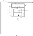
- a roadside sensing apparatus 1 according to an embodiment of the present disclosure will be described below with reference to FIGS. 1 and 2 .
- the roadside sensing apparatus 1 includes a base 10, a scanning device 20 and a driving device 30.
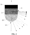
- the scanning device 20 includes a main scanning unit 21 and a sub-scanning unit 22, the main scanning unit 21 is located above the sub-scanning unit 22, a lower boundary line of a first scanning field of view of the main scanning unit 21 coincides or intersects with an upper boundary line of a second scanning field of view of the sub-scanning unit 22.
- the driving device 30 is provided on the base 10, the driving device 30 is drivingly connected to the scanning device 20, to drive the scanning device to rotate in a horizontal direction.
- the main scanning unit 21 and the sub-scanning unit 22 may use a lidar respectively.
- the lidar includes a photoelectric detection module and a data preprocessing module.
- the photoelectric detection module includes a photoelectric detection element and a digital-to-analog converter.
- the photoelectric detection element is configured to detect the target environment and generate a digital optical signal.
- the digital-to-analog conversion module is configured to receive the optical signal from the photoelectric detection element and convert the optical signal into an analog signal.
- the data preprocessing module is configured to receive the analog signal from the digital-to-analog conversion module and preprocessing the analog signal to generate scan data.
- the data processing device of the roadside sensing apparatus 1 receives scan data from the main scanning unit 21 and the sub-scanning unit 22 respectively, and obtains structured data through corresponding data processing.
- the main scanning unit 21 and the sub-scanning unit 22 may also use a photoelectric detection module respectively.
- the data processing device of the roadside sensing apparatus 1 receives an analog signal from the main scanning unit 21 and the sub-scanning unit 22 respectively, and obtains structured data through corresponding data processing.
- the scanning device 20 is driven by the driving device 30 to rotate clockwise or counterclockwise in the horizontal direction, so that the field angles of the first scanning field of view of the main scanning unit 21 and the second scanning field of view of the sub-scanning unit 22 in the horizontal direction both are 360 degrees, so that the omnidirectional scanning of the scanning device 20 in the horizontal direction is realized.
- the main scanning area, corresponding to the first scanning field of view, in the target environment is annular
- the sub-scanning area, corresponding to the second scanning field of view, in the target environment is annular or circular.
- the first scanning field of view of the main scanning unit 21 may be a vertical scanning field of view of the main scanning unit 21 in the vertical direction
- the second scanning field of view of the sub-scanning unit 22 may be a vertical scanning field of view of the sub-scanning unit 22 in the vertical direction.
- the main scanning unit 21 and the sub-scanning unit 22 are arranged in the vertical direction, and the main scanning unit 21 is located above the sub-scanning unit 22.
- the first scanning field of view of the main scanning unit 21 may be inclined downward at a small angle relative to the horizontal direction, and the second scanning field of view of the sub-scanning unit 22 may be inclined downward at a large angle relative to the horizontal direction.
- the lower boundary line of the first scanning field of view coincides or intersects with the upper boundary line of the second scanning field of view, so that the main scanning area corresponding to the main scanning unit 21 meets or partially overlaps with the sub-scanning area corresponding to the sub-scanning unit 22, so that the overall scanning area of the scanning device 20 forms a complete ring or circle, thereby eliminating the blind area between the main scanning area of the main scanning unit 21 and the sub-scanning area of the sub-scanning unit 22.
- the embodiments of the present disclosure do not specifically limit the arrangement of the base 10 and the scanning device 20.
- the scanning device 20 may be disposed below the base 10, and for another example, the scanning device 20 may also be disposed above the base 10.
- the scanning device 20 may be disposed below the base 10.
- the base 10 can be arranged on a support rod on the roadside, so that the roadside sensing apparatus 1 has a certain height relative to the ground.
- the height of the base 10 relative to the ground can be set between 6 meters and 7 meters, so that the scanning device 20 forms a certain scanning area and scanning distance in the target environment.
- the roadside sensing apparatus 1 of the embodiment of the present disclosure can be applied to an intelligent transportation system and is arranged on the roadside, and the roadside sensing apparatus 1 is used to detect the target environment on the roadside and generate corresponding sensing data.
- the sensing data can be structured data, which can represent a distance, an orientation, a speed, an attitude, a shape and other information of a target object in a target environment.
- the roadside sensing apparatus 1 After generating the sensing data, the roadside sensing apparatus 1 sends the same to an edge computation unit on the roadside, and the edge computation unit implements other processing procedures such as tracking, identifying, and path planning of the target object according to the sensing data.
- the fisheye camera can independently achieve a wide range of surveillance, and the monitoring area of the fisheye camera can be used as a gap-filling area for the monitoring area of the surveillance camera.
- the image acquired by the fisheye camera has large distortion and low precision, which cannot meet the precise measurement requirements of parameters such as a distance and a speed of a target object in the full range.
- the roadside sensing apparatus 1 in the related art that adopts a combination of a radar sensor and a fisheye camera, although omnidirectional monitoring without blind areas can also be realized, due to different forms of data output by the radar sensor and the fisheye camera, the data fusion effect is relatively poor, resulting in large errors in the final data. Therefore, the roadside sensing apparatus 1 in this way cannot meet the precise measurement requirements of parameters such as the distance and speed of the target object in the full range. In addition, the above two forms of roadside sensing apparatuses cannot also meet the detection requirements in working conditions such as a night or a fog, and are less practical.
- the scanning device 20 by setting the scanning device 20 to include a main scanning unit 21 and a sub-scanning unit 22, the main scanning unit 21 is located above the sub-scanning unit 22, and the lower boundary line of the first scanning field of view of the main scanning unit 21 coincides or intersects with the upper boundary line of the second scanning field of view, and the scanning device 20 is driven by the driving device 30 to rotate in the horizontal direction, so that the sub-scanning area corresponding to the sub-scanning unit 22 can be used as a gap-filling area for the main scanning area corresponding to the main scanning unit 21, which eliminates the blind area between the main scanning area and the sub-scanning area, and satisfies the requirements of omnidirectional detection without blind areas of the target environment.
- the main scanning unit 21 and the sub-scanning unit 22 can be separately configured for different detection distances in the target environment, which realizes the high integration of the roadside sensing apparatus 1, and can realize the integrated installation for multiple scanning units, reduce the system integration difficulty and engineering difficulty of the roadside sensing apparatus, thereby reducing hardware costs.
- the main scanning unit 21 and the sub-scanning unit 22 can use various scanning devices, for example, the main scanning unit 21 and the sub-scanning unit 22 both can use a lidar.
- this solves the technical problems that the roadside sensing apparatus 1 in the related art cannot achieve omnidirectional detection without blind areas and has low detection accuracy and poor integration, can meet the detection requirements in different working conditions and improves the detection accuracy of the gap-filling area, thereby improving the recognition accuracy of the back-end equipment, which is conducive to the realization of omnidirectional high-precision detection without blind areas.
- the lower boundary line of the second scanning field of view of the sub-scanning unit 22 is parallel to a vertical direction or at a negative angle with respect to the vertical direction.
- the lower boundary line of the second scanning field of view of the sub-scanning unit 22 is at a negative angle with respect to the vertical direction, which can be understood that the angle between the lower boundary line of the second scanning field of view and the vertical line passing through the laser emission origin is a negative value.
- the angle between the upper boundary line of the second scanning field of view and the vertical line passing through the laser emission origin is a positive value.
- the sub-scanning area formed by the sub-scanning field of view corresponding to the sub-scanning unit 22 in the target environment is circular, that is, there is no blind area, which cannot be detected, in the sub-scanning area, so that there is no detection blind area in the overall scanning area corresponding to the scanning device 20, realizing the detection requirements of the roadside sensing apparatus 1 without any blind area in all directions.
- the lower boundary line of the second scanning field of view is set parallel to the vertical direction, that is, the lower boundary line of the second scanning field of view coincides with the vertical line passing through the laser emission origin. Therefore, while ensuring the detection requirements of the roadside sensing apparatus 1 without any blind area in all directions, the waste of the beams of the sub-scanning unit 22 in the overlapping area can be avoided, and the utilization rate of the scanning performance of the sub-scanning unit 22 can be improved.
- a field angle ⁇ of an overall scanning field of view formed by the first scanning field of view and the second scanning field of view is 80 degrees to 90 degrees.
- the upper boundary line of the overall scanning field of view formed by the first scanning field of view and the second scanning field of view is the upper boundary line of the first scanning field of view
- the lower boundary line of the overall scanning field of view is the lower boundary line of the second scanning field of view
- the field angle ⁇ corresponding to the overall scanning field of view is the included angle between the upper boundary line of the first scanning field of view and the lower boundary line of the second scanning field of view
- the field angle ⁇ of the overall scanning field of view is greater than or equal to 80 degrees and less than or equal to 90 degrees.
- the field angle ⁇ of the scanning field of view is less than 80 degrees, the overall scanning distance corresponding to the overall scanning field of view of the scanning device is small, which cannot meet the long-distance detection requirements. Therefore, it is necessary to set the field angle ⁇ to be greater than or equal to 80 degrees.
- the height of the roadside sensing apparatus 1 relative to the ground of the target environment may be 6.5 meters, and the field angle ⁇ of the overall scanning field of view formed by the first scanning field of view and the second scanning field of view may be 86.9 meters. Therefore, the overall scanning area corresponding to the overall scanning field of view is a circular area with the roadside sensing apparatus 1 as the center and a radius of 120 meters, that is, the detection distance of the roadside sensing apparatus 1 in the target environment is 120 meters.
- the setting height of the roadside sensing apparatus 1 and the field angle of the overall scanning field of view can be specifically set according to actual detection requirements, and the above is only an exemplary description.
- the roadside sensing apparatus 1 can be provided with a relatively long detection distance, so as to meet the requirements for sensing a wide range of roadside environment.
- a field angle ⁇ corresponding to the first scanning field of view is 20 degrees to 30 degrees
- a field angle ⁇ corresponding to the second scanning field of view is 55 degrees to 65 degrees.
- the main scanning unit 21 is used for long-distance detection of the target environment, and the main scanning area has a larger range; the sub-scanning unit 22 is used for short-range detection of the target environment, and the sub-scanning area is small.
- the number of laser beams of the main scanning unit 21 is much larger than that of the sub-scanning unit 22, and the equipment integration requirement of the main scanning unit 21 is also much higher than that of the sub-scanning unit 22.
- the number of laser beams of the main scanning unit 21 can be appropriately reduced, thereby reducing the hardware cost and processing difficulty of the main scanning unit 21, and further reducing the overall processing difficulty and hardware cost of the roadside sensing apparatus 1.
- a density of laser beams of the scanning device increases gradually in a direction toward the upper boundary line of the first scanning field of view.
- the density of laser beams in the first scanning field of view increases gradually in the direction from the lower boundary line to the upper boundary line
- the density of laser beams in the second scanning field of view increases gradually in the direction from the lower boundary line to the upper boundary line.
- the density of laser beams of the first scanning field of view in the overlapping area is approximately same as that of the second scanning field of view in the overlapping area.
- the number of equivalent laser beams of the overall scanning field of view corresponding to the scanning device 20 may be 300.
- the uniform distribution, in the radial direction, of the laser beams within the overall scanning range corresponding to the overall scanning field of view can be ensured, so as to ensure the overall consistency of the detection performance of the scanning device 20, especially for a target object at a long distance, higher detection accuracy still can be ensured.
- the driving device 30 includes a drive motor 31 and a transmission shaft 32, an output shaft of the drive motor 31 is drivingly connected to the transmission shaft 32, and the transmission shaft 32 is fixedly connected to the scanning device 20.
- the drive motor 31 is disposed inside the base 10, the transmission shaft 32 is drivingly connected with the output shaft of the drive motor 31, and the transmission shaft 32 extends downward from the interior of the base 10 out of the base 10.
- the main scanning unit 21 and the sub-scanning unit 22 are integrally arranged, and the transmission shaft 32 is fixedly connected with the main scanning unit 21. Therefore, the transmission shaft 32 is driven to rotate by the drive motor 31, thereby driving the main scanning unit 21 and the sub-scanning unit 22 to rotate synchronously.
- the transmission shaft 32 may be arranged along the vertical direction, so that the rotation axis of the scanning device 20 is arranged parallel to the vertical direction.
- the rotational frequency of the driving device 30 for driving the scanning device 20 may be 10 Hz to 20 Hz, that is, the rotational speed of the scanning device 20 is 600 r/min to 1200 r/min.
- the rotational frequency of the driving device 30 for driving the scanning device 20 may be 15 Hz, that is, the rotational speed of the scanning device 20 is 900 r/min.
- the main scanning unit 21 and the sub-scanning unit 22 may also adopt a non-integrated arrangement.
- both ends of the transmission shaft 32 can extend to the upper and lower ends of the base 10 respectively
- the main scanning unit 21 is located above the base 10 and is fixedly connected to the upper end of the transmission shaft 32
- the sub-scanning unit 22 is located below the base 10 and is fixedly connected with the lower end of the transmission shaft 32.
- the omnidirectional rotation of the scanning device in the horizontal direction can be realized, the structure of the driving device 30 is simple, and the assembly of the scanning device 20 and the driving device 30 is also convenient.
- a data processing device is provided inside the base 10, and the data processing device is configured to receive scan data of the main scanning unit 21 and the sub-scanning unit 22, and generate structured data.
- the data processing device may be specifically configured to: receive scan data from the main scanning unit 21 and the sub-scanning unit 22 respectively, then perform normalization preprocessing on a plurality of scan data respectively to obtain a plurality of preprocessed data, and finally perform data fusion processing and structured feature extraction processing on the plurality of preprocessed data to generate structured data.
- the structured data generated by the data processing device has a certain physical meaning and can be used to represent certain semantic information.
- the roadside computation unit can realize predictive perception, path planning and early warning of the target object and other functions in the target environment based on the structured data.
- the base 10 can have a certain AI computing power.
- the roadside sensing apparatus 1 in the embodiment of the present disclosure can reduce the calculation amount and performance requirements of the roadside computation unit, so that the data processing efficiency of the roadside computation unit is improved and the equipment cost of the roadside computation unit is reduced.
- a control device 11 is provided inside the base 10, and the control device 11 communicates with the driving device 30, to control the driving device 30 to drive the scanning device 20 to rotate.
- the communication method between the control device 11 and the driving device 30 may be electrical communication or wireless communication.
- control device may also control the rotational speed of the driving device to adjust the scanning frequency of the scanning device in the circumferential direction, so as to improve the applicable range of the roadside sensing apparatus.
- control device 11 by integrating the control device 11 inside the base 10, the control device 11 is used to send a driving signal to the driving device 30, to control the driving device 30 to be turned on or off, so as to control the scanning device 20 to rotate or rest in the horizontal direction, thereby further improving the integration of the roadside sensing apparatus.
- control device 11 communicates with the scanning device 20, to control the scanning device 20 to be turned on or off according to a rotation angle of the scanning device 20.
- the communication method between the control device 11 and the scanning device 20 may be electrical communication or wireless communication.
- the main scanning unit 21 and/or the sub-scanning unit 22 are/is controlled to be turned on when the main scanning unit 21 and the sub-scanning unit 22 are rotated into the angle range of the horizontal field of view corresponding to the target area, and the main scanning unit 21 and/or the sub-scanning unit 22 are/is controlled to be turned off when being rotated into another area of the target environment.
- the target area is only located in the main scanning area corresponding to the main scanning unit 21
- only the main scanning unit 21 is controlled to be turned on when being rotated into the angle range of the corresponding horizontal field of view.
- the target area is only located in the sub-scanning area corresponding to the sub-scanning unit 22
- only the sub-scanning unit 22 is controlled to be turned on when being rotated into the angle range of the corresponding horizontal field of view.
- the main scanning unit 21 and the sub-scanning unit 22 are controlled to be turned on when being rotated into the angle range of the corresponding horizontal field of view.
- the target area may be a road and areas on both sides of the road, and the scanning device 20 does not need to be turned on in other areas.
- the main scanning unit 21 and/or the sub-scanning unit 22 are/is controlled to be turned on.
- the main scanning unit 21 and the sub-scanning unit 22 are controlled to be turned off.
- the scanning device 20 can be controlled to be turned on or off for a specific area in the target environment, so that on the basis of satisfying the detection requirements for the specific area, there is no need to detect other areas, so as to reduce operating costs of the roadside sensing apparatus 1.
- an intelligent transportation system includes the roadside sensing apparatus 1 according to the above-mentioned embodiments of the present disclosure and a roadside computation unit.
- the roadside computation unit is configured for receiving structured data from the roadside sensing apparatus 1 and performing data computation processing on the structured data.
- the roadside computation unit may be an edge computation unit, which is configured to receive the structured data sent by the roadside sensing apparatus 1, and perform data computation processing on the structured data, to obtain relevant information about the target object in the target environment, so as to realize predictive perception, path planning and early warning of the target object and other functions.
- edge computation unit configured to receive the structured data sent by the roadside sensing apparatus 1, and perform data computation processing on the structured data, to obtain relevant information about the target object in the target environment, so as to realize predictive perception, path planning and early warning of the target object and other functions.
- the intelligent transportation system may also include a cloud server and a vehicle-end server, and any two of the roadside computation unit, the cloud server and the vehicle-end server may conduct information exchange.
- the intelligent transportation system reduces the deployment cost and hardware cost of the intelligent transportation system by utilizing the roadside sensing apparatus 1 according to the above-mentioned embodiment of the present disclosure, and realizes a large range of high-precision detection without any blind area, of the roadside target environment, which ensures the efficiency and accuracy of tracking, recognition and path planning of the target object and other functions.
- first and second are only used for descriptive purposes, and are not to be construed as indicating or suggesting relative importance or implicitly indicating the number of indicated technical features.
- the features defined with “first” and “second” may explicitly or implicitly include one or more of these features.
- a plurality of means two or more, unless otherwise expressively and specifically defined.
- the terms “mount”, “link”, “connect”, “fix”, etc. should be understood in the broad senses, for example, may be a fixed connection, a detachable connection or integration; may be a mechanical connection, an electrical connection or communication; and may be a direction connection, an indirect connection through an intermediate medium, or internal communication between two elements or an interaction therebetween.
- the specific meanings of the above terms in the present disclosure may be understood according to specific circumstances.
- a first feature being “on” or “under” a second feature may indicate a direct contact between the first feature and the second feature, or an indirect contact therebetween via another feature.
- the first feature being “on”, “above”, or “over” the second feature may indicate that the first feature is directly or obliquely above the second feature, or merely indicate that the level of the first feature is higher than that of the second feature.
- the first feature being “under”, “below”, or “beneath” the second feature may indicate that the first feature is directly or obliquely below the second feature, or merely indicate that the level of the first feature is lower than that of the second feature.
Landscapes
- Engineering & Computer Science (AREA)
- Physics & Mathematics (AREA)
- General Physics & Mathematics (AREA)
- Computer Networks & Wireless Communication (AREA)
- Radar, Positioning & Navigation (AREA)
- Remote Sensing (AREA)
- Electromagnetism (AREA)
- Traffic Control Systems (AREA)
Applications Claiming Priority (2)
| Application Number | Priority Date | Filing Date | Title |
|---|---|---|---|
| CN202110602160.3A CN113189609A (zh) | 2021-05-31 | 2021-05-31 | 基座、路侧传感设备以及智能交通系统 |
| CN202110802502.6A CN113341429A (zh) | 2021-05-31 | 2021-07-15 | 路侧传感设备以及智能交通系统 |
Publications (2)
| Publication Number | Publication Date |
|---|---|
| EP4053590A2 true EP4053590A2 (de) | 2022-09-07 |
| EP4053590A3 EP4053590A3 (de) | 2022-10-19 |
Family
ID=81850675
Family Applications (1)
| Application Number | Title | Priority Date | Filing Date |
|---|---|---|---|
| EP22173794.3A Withdrawn EP4053590A3 (de) | 2021-05-31 | 2022-05-17 | Fahrbahnsensorvorrichtung und intelligentes transportsystem |
Country Status (1)
| Country | Link |
|---|---|
| EP (1) | EP4053590A3 (de) |
Family Cites Families (3)
| Publication number | Priority date | Publication date | Assignee | Title |
|---|---|---|---|---|
| CN209656882U (zh) * | 2018-12-27 | 2019-11-19 | 北京万集科技股份有限公司 | 一种路侧激光雷达 |
| EP3712647B1 (de) * | 2019-03-18 | 2021-04-28 | Sick Ag | Optoelektronischer sensor und verfahren zur erfassung von objekten |
| CN212364571U (zh) * | 2019-10-25 | 2021-01-15 | 北京万集科技股份有限公司 | 一种大视场的路侧激光雷达 |
-
2022
- 2022-05-17 EP EP22173794.3A patent/EP4053590A3/de not_active Withdrawn
Also Published As
| Publication number | Publication date |
|---|---|
| EP4053590A3 (de) | 2022-10-19 |
Similar Documents
| Publication | Publication Date | Title |
|---|---|---|
| US20220284806A1 (en) | Roadside sensing apparatus and intelligent transportation system | |
| US20220236392A1 (en) | Detection device and method for adjusting parameter thereof | |
| CN109254286B (zh) | 机载激光雷达光学扫描装置 | |
| CN107121683B (zh) | 基于多个激光器的多线激光雷达 | |
| CN107271983B (zh) | 多线激光雷达 | |
| CN106443699A (zh) | 一种多组合式激光雷达装置及其扫描方法 | |
| CN210864033U (zh) | 一种扫描装置及激光雷达系统 | |
| US11645759B1 (en) | Background filtering method and background filtering system based on roadside solid-state lidar | |
| CN217060495U (zh) | 一种用于测风激光雷达的光学天线及测风激光雷达 | |
| EP4053590A2 (de) | Fahrbahnsensorvorrichtung und intelligentes transportsystem | |
| CN112698353B (zh) | 一种结构线激光与倾斜双目组合的车载视觉雷达系统 | |
| CN202583889U (zh) | Dcs监控激光标校太阳能聚光反射镜定位装置 | |
| CN115963472A (zh) | 扫描范围可调的旋转式远程光学扫描装置 | |
| CN109917351B (zh) | 激光雷达的发射系统及其控制方法、激光雷达 | |
| CN218630192U (zh) | 一种激光雷达系统及移动设备 | |
| CN117630914A (zh) | 一种面向低空无人机探测的雷达光学红外一体化探测系统及方法 | |
| CN215340333U (zh) | 基座、路侧传感设备以及智能交通系统 | |
| CN214473910U (zh) | 一种激光雷达及一种无人机 | |
| CN115291196A (zh) | 一种激光净空雷达安装姿态的标定方法 | |
| CN111708031B (zh) | 一种激光雷达 | |
| CN105549026A (zh) | 一种多线光学扫描测距装置及其方法 | |
| CN211905686U (zh) | 一种基于激光雷达和全景视觉的环境感知系统 | |
| CN210534336U (zh) | 一种激光雷达 | |
| CN117311245B (zh) | 一种升空式频谱监测设备及控制方法 | |
| CN210604981U (zh) | 多线激光测距雷达 |
Legal Events
| Date | Code | Title | Description |
|---|---|---|---|
| PUAI | Public reference made under article 153(3) epc to a published international application that has entered the european phase |
Free format text: ORIGINAL CODE: 0009012 |
|
| STAA | Information on the status of an ep patent application or granted ep patent |
Free format text: STATUS: REQUEST FOR EXAMINATION WAS MADE |
|
| 17P | Request for examination filed |
Effective date: 20220517 |
|
| AK | Designated contracting states |
Kind code of ref document: A2 Designated state(s): AL AT BE BG CH CY CZ DE DK EE ES FI FR GB GR HR HU IE IS IT LI LT LU LV MC MK MT NL NO PL PT RO RS SE SI SK SM TR |
|
| PUAL | Search report despatched |
Free format text: ORIGINAL CODE: 0009013 |
|
| AK | Designated contracting states |
Kind code of ref document: A3 Designated state(s): AL AT BE BG CH CY CZ DE DK EE ES FI FR GB GR HR HU IE IS IT LI LT LU LV MC MK MT NL NO PL PT RO RS SE SI SK SM TR |
|
| RIC1 | Information provided on ipc code assigned before grant |
Ipc: G08G 1/04 20060101ALI20220912BHEP Ipc: G01S 17/931 20200101ALI20220912BHEP Ipc: G01S 7/481 20060101AFI20220912BHEP |
|
| STAA | Information on the status of an ep patent application or granted ep patent |
Free format text: STATUS: THE APPLICATION IS DEEMED TO BE WITHDRAWN |
|
| 18D | Application deemed to be withdrawn |
Effective date: 20230420 |