EP4053496A1 - Vehicle operation pedal device - Google Patents
Vehicle operation pedal device Download PDFInfo
- Publication number
- EP4053496A1 EP4053496A1 EP20881513.4A EP20881513A EP4053496A1 EP 4053496 A1 EP4053496 A1 EP 4053496A1 EP 20881513 A EP20881513 A EP 20881513A EP 4053496 A1 EP4053496 A1 EP 4053496A1
- Authority
- EP
- European Patent Office
- Prior art keywords
- operating pedal
- magnet
- holder
- support member
- vehicle operating
- Prior art date
- Legal status (The legal status is an assumption and is not a legal conclusion. Google has not performed a legal analysis and makes no representation as to the accuracy of the status listed.)
- Pending
Links
- 238000003780 insertion Methods 0.000 claims description 11
- 230000037431 insertion Effects 0.000 claims description 11
- 230000004048 modification Effects 0.000 description 13
- 238000012986 modification Methods 0.000 description 13
- 238000010586 diagram Methods 0.000 description 12
- 238000001514 detection method Methods 0.000 description 9
- 230000002265 prevention Effects 0.000 description 4
- 238000005516 engineering process Methods 0.000 description 2
- 230000013011 mating Effects 0.000 description 2
- 230000000694 effects Effects 0.000 description 1
- 230000000149 penetrating effect Effects 0.000 description 1
Images


Classifications
-
- G—PHYSICS
- G05—CONTROLLING; REGULATING
- G05G—CONTROL DEVICES OR SYSTEMS INSOFAR AS CHARACTERISED BY MECHANICAL FEATURES ONLY
- G05G1/00—Controlling members, e.g. knobs or handles; Assemblies or arrangements thereof; Indicating position of controlling members
- G05G1/30—Controlling members actuated by foot
- G05G1/38—Controlling members actuated by foot comprising means to continuously detect pedal position
-
- G—PHYSICS
- G01—MEASURING; TESTING
- G01B—MEASURING LENGTH, THICKNESS OR SIMILAR LINEAR DIMENSIONS; MEASURING ANGLES; MEASURING AREAS; MEASURING IRREGULARITIES OF SURFACES OR CONTOURS
- G01B7/00—Measuring arrangements characterised by the use of electric or magnetic techniques
- G01B7/30—Measuring arrangements characterised by the use of electric or magnetic techniques for measuring angles or tapers; for testing the alignment of axes
-
- B—PERFORMING OPERATIONS; TRANSPORTING
- B60—VEHICLES IN GENERAL
- B60K—ARRANGEMENT OR MOUNTING OF PROPULSION UNITS OR OF TRANSMISSIONS IN VEHICLES; ARRANGEMENT OR MOUNTING OF PLURAL DIVERSE PRIME-MOVERS IN VEHICLES; AUXILIARY DRIVES FOR VEHICLES; INSTRUMENTATION OR DASHBOARDS FOR VEHICLES; ARRANGEMENTS IN CONNECTION WITH COOLING, AIR INTAKE, GAS EXHAUST OR FUEL SUPPLY OF PROPULSION UNITS IN VEHICLES
- B60K23/00—Arrangement or mounting of control devices for vehicle transmissions, or parts thereof, not otherwise provided for
- B60K23/02—Arrangement or mounting of control devices for vehicle transmissions, or parts thereof, not otherwise provided for for main transmission clutches
-
- B—PERFORMING OPERATIONS; TRANSPORTING
- B60—VEHICLES IN GENERAL
- B60K—ARRANGEMENT OR MOUNTING OF PROPULSION UNITS OR OF TRANSMISSIONS IN VEHICLES; ARRANGEMENT OR MOUNTING OF PLURAL DIVERSE PRIME-MOVERS IN VEHICLES; AUXILIARY DRIVES FOR VEHICLES; INSTRUMENTATION OR DASHBOARDS FOR VEHICLES; ARRANGEMENTS IN CONNECTION WITH COOLING, AIR INTAKE, GAS EXHAUST OR FUEL SUPPLY OF PROPULSION UNITS IN VEHICLES
- B60K26/00—Arrangements or mounting of propulsion unit control devices in vehicles
- B60K26/02—Arrangements or mounting of propulsion unit control devices in vehicles of initiating means or elements
-
- B—PERFORMING OPERATIONS; TRANSPORTING
- B60—VEHICLES IN GENERAL
- B60T—VEHICLE BRAKE CONTROL SYSTEMS OR PARTS THEREOF; BRAKE CONTROL SYSTEMS OR PARTS THEREOF, IN GENERAL; ARRANGEMENT OF BRAKING ELEMENTS ON VEHICLES IN GENERAL; PORTABLE DEVICES FOR PREVENTING UNWANTED MOVEMENT OF VEHICLES; VEHICLE MODIFICATIONS TO FACILITATE COOLING OF BRAKES
- B60T7/00—Brake-action initiating means
- B60T7/02—Brake-action initiating means for personal initiation
- B60T7/04—Brake-action initiating means for personal initiation foot actuated
- B60T7/042—Brake-action initiating means for personal initiation foot actuated by electrical means, e.g. using travel or force sensors
-
- B—PERFORMING OPERATIONS; TRANSPORTING
- B60—VEHICLES IN GENERAL
- B60T—VEHICLE BRAKE CONTROL SYSTEMS OR PARTS THEREOF; BRAKE CONTROL SYSTEMS OR PARTS THEREOF, IN GENERAL; ARRANGEMENT OF BRAKING ELEMENTS ON VEHICLES IN GENERAL; PORTABLE DEVICES FOR PREVENTING UNWANTED MOVEMENT OF VEHICLES; VEHICLE MODIFICATIONS TO FACILITATE COOLING OF BRAKES
- B60T7/00—Brake-action initiating means
- B60T7/02—Brake-action initiating means for personal initiation
- B60T7/04—Brake-action initiating means for personal initiation foot actuated
- B60T7/06—Disposition of pedal
-
- G—PHYSICS
- G01—MEASURING; TESTING
- G01D—MEASURING NOT SPECIALLY ADAPTED FOR A SPECIFIC VARIABLE; ARRANGEMENTS FOR MEASURING TWO OR MORE VARIABLES NOT COVERED IN A SINGLE OTHER SUBCLASS; TARIFF METERING APPARATUS; MEASURING OR TESTING NOT OTHERWISE PROVIDED FOR
- G01D5/00—Mechanical means for transferring the output of a sensing member; Means for converting the output of a sensing member to another variable where the form or nature of the sensing member does not constrain the means for converting; Transducers not specially adapted for a specific variable
- G01D5/12—Mechanical means for transferring the output of a sensing member; Means for converting the output of a sensing member to another variable where the form or nature of the sensing member does not constrain the means for converting; Transducers not specially adapted for a specific variable using electric or magnetic means
- G01D5/14—Mechanical means for transferring the output of a sensing member; Means for converting the output of a sensing member to another variable where the form or nature of the sensing member does not constrain the means for converting; Transducers not specially adapted for a specific variable using electric or magnetic means influencing the magnitude of a current or voltage
- G01D5/142—Mechanical means for transferring the output of a sensing member; Means for converting the output of a sensing member to another variable where the form or nature of the sensing member does not constrain the means for converting; Transducers not specially adapted for a specific variable using electric or magnetic means influencing the magnitude of a current or voltage using Hall-effect devices
- G01D5/145—Mechanical means for transferring the output of a sensing member; Means for converting the output of a sensing member to another variable where the form or nature of the sensing member does not constrain the means for converting; Transducers not specially adapted for a specific variable using electric or magnetic means influencing the magnitude of a current or voltage using Hall-effect devices influenced by the relative movement between the Hall device and magnetic fields
-
- G—PHYSICS
- G01—MEASURING; TESTING
- G01D—MEASURING NOT SPECIALLY ADAPTED FOR A SPECIFIC VARIABLE; ARRANGEMENTS FOR MEASURING TWO OR MORE VARIABLES NOT COVERED IN A SINGLE OTHER SUBCLASS; TARIFF METERING APPARATUS; MEASURING OR TESTING NOT OTHERWISE PROVIDED FOR
- G01D5/00—Mechanical means for transferring the output of a sensing member; Means for converting the output of a sensing member to another variable where the form or nature of the sensing member does not constrain the means for converting; Transducers not specially adapted for a specific variable
- G01D5/12—Mechanical means for transferring the output of a sensing member; Means for converting the output of a sensing member to another variable where the form or nature of the sensing member does not constrain the means for converting; Transducers not specially adapted for a specific variable using electric or magnetic means
- G01D5/244—Mechanical means for transferring the output of a sensing member; Means for converting the output of a sensing member to another variable where the form or nature of the sensing member does not constrain the means for converting; Transducers not specially adapted for a specific variable using electric or magnetic means influencing characteristics of pulses or pulse trains; generating pulses or pulse trains
- G01D5/245—Mechanical means for transferring the output of a sensing member; Means for converting the output of a sensing member to another variable where the form or nature of the sensing member does not constrain the means for converting; Transducers not specially adapted for a specific variable using electric or magnetic means influencing characteristics of pulses or pulse trains; generating pulses or pulse trains using a variable number of pulses in a train
-
- G—PHYSICS
- G05—CONTROLLING; REGULATING
- G05G—CONTROL DEVICES OR SYSTEMS INSOFAR AS CHARACTERISED BY MECHANICAL FEATURES ONLY
- G05G1/00—Controlling members, e.g. knobs or handles; Assemblies or arrangements thereof; Indicating position of controlling members
- G05G1/30—Controlling members actuated by foot
- G05G1/44—Controlling members actuated by foot pivoting
Definitions
- the present invention relates to a vehicle operating pedal apparatus including an angle sensor that detects the angle of rotation of an operating pedal.
- a technology described in Patent Literature 1 below is an operation amount detection apparatus, and includes a stroke sensor that detects the stroke of the tread of a pedal section (a pedal stroke).
- the stroke sensor includes a sensor body, and a sensor arm (a part of the sensor body) provided in such a manner as to be pivotable on a sensor pivot axis relative to the sensor body.
- the sensor arm has a pair of bifurcations that are two branches divided and extend substantially parallel.
- a guide groove that extends radially outward from the sensor pivot axis and is formed in a straight line is provided between the pair of bifurcations.
- a pin fixed to the pedal arm is slidably engaged in the guide groove.
- the pedal arm has a substantially arc shape, is fixed to the upper end of the pedal section, and pivots integrally with the pedal section.
- the pin is fixed to the upper end of the pedal arm, and protrudes in a direction substantially orthogonal to the pedal arm extension direction (toward the stroke sensor).
- the present invention has been made, considering the above point, and an objective thereof is to provide a vehicle operating pedal apparatus having a compact space for mounting an angle sensor that detects the angle of rotation of an operating pedal.
- the invention according to claim 1 is a vehicle operating pedal apparatus which includes: a pair of support members fixed to a vehicle member, the pair of support members facing each other; an operating pedal provided at one end with a tubular boss for the pedal, the operating pedal being supported between the pair of support members in such a manner as to be pivotable on a pivot axis member that is inserted into holes provided in the support members and the boss; and an angle sensor configured to detect the angle of rotation of the operating pedal.
- the angle sensor includes: a Hall device provided on an inner side between the pair of support members; and a magnet provided at the one end of the operating pedal, facing the Hall device, the magnet being configured to detect the magnetic field of the Hall device.
- the invention according to claim 2 is the vehicle operating pedal apparatus according to claim 1, in which the Hall device and the magnet face each other in a position that is closer to the pivot axis member than a side surface at the one end of the operating pedal.
- the invention according to claim 3 is the vehicle operating pedal apparatus according to claim 1, in which the magnet is placed, in an arc shape that is equidistant from a pivot center line of the operating pedal, on a side surface at the one end of the operating pedal.
- the invention according to claim 4 is the vehicle operating pedal apparatus according to any one of claims 1 to 3, including: a device holder to which the Hall device is fixed, the device holder being attached to the support member; a magnet holder to which the magnet is fixed, the magnet holder being attached to the one end of the operating pedal; and a cover jutting out from the device holder or the magnet holder, the cover being disposed in at least part of a gap across which the Hall device and the magnet face each other, and of an outer space.
- the invention according to claim 5 is the vehicle operating pedal apparatus according to claim 4, in which the cover is provided to the device holder.
- the invention according to claim 6 is the vehicle operating pedal apparatus according to claim 4, in which the cover is provided to the magnet holder.
- the invention according to claim 7 is the vehicle operating pedal apparatus according to any one of claims 4 to 6, in which the cover is provided to at least one of the upper side of the gap, the front side of a vehicle, or the back side of the vehicle.
- the invention according to claim 8 is the vehicle operating pedal apparatus according to any one of claims 4 to 7, in which the cover has a surface facing the outer space, the surface inclining downward from a distal end toward a proximal end thereof.
- the invention according to claim 9 is the vehicle operating pedal apparatus according to claim 1 or 2, further including: a device holder including a protrusion to which the Hall device is fixed, the device holder being attached to the support member from the outside of the support member, wherein the protrusion of the device holder is inserted from the outer side to the inner side of the support member through an insertion hole of the support member to provide the Hall device on the inner side between the pair of support members.
- a vehicle operating pedal apparatus of the present invention has a compact space for mounting an angle sensor that detects the angle of rotation of an operating pedal.
- a vehicle operating pedal apparatus is described hereinafter on the basis of materialized embodiments thereof with reference to the drawings.
- the vehicle operating pedal apparatus according to the present invention is attached to a vehicle to be used as a brake pedal.
- the vehicle operating pedal apparatus according to the present invention may be used as a vehicle pedal (for example, the accelerator pedal or clutch pedal) other than the brake pedal.
- the direction into the page is forward, and the direction out of the page is backward.
- the direction orthogonal to the page in Figs. 4 , 9 , 14 , 19 , 24 , and 29 is the front-and-back direction.
- the same points are valid with regard to the cross-sectional views of Figs. 5 , 10 , 15 , 20 , 25 , and 30 to 34 .
- the direction into the page is downward, and the direction out of the page is upward.
- the direction orthogonal to the page in Fig. 35 is the up-and-down direction.
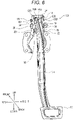
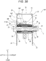
- a vehicle operating pedal apparatus 10A includes an operating pedal 12 and a support member 14, and is mounted on a vehicle.
- a stepping part 16 is provided at the lower end of the operating pedal 12.
- a tubular boss 18 is fixed to the upper end of the operating pedal 12, penetrating the upper end.
- a collar 29 on which a pair of bushings 28 is fitted at the left and right ends of the collar 29 is fitted in the boss 18. Consequently, the tubular portions of the bushings 28 are placed between the boss 18 and the collar 29.
- the support member 14 includes a left support member 20, a right support member 22, and an upper middle support member 24, and is fixed to the vehicle (for example, a dash panel P).
- the left support member 20 and the right support member 22 are coupled to the upper middle support member 24 from the front ends across the upper ends of the left support member 20 and the right support member 22, and face each other in the left-and-right direction.
- the left support member 20 is provided with a left pivot hole 21.
- the right support member 22 is provided with a right pivot hole 23.
- the boss 18 of the operating pedal 12 is disposed between the left pivot hole 21 and the right pivot hole 23 to cause the left pivot hole 21 and the right pivot hole 23 to communicate with each other in the left-and-right direction via the collar 29 in the boss 18. With the pivot holes communicating with each other, a pivot bolt 26 is passed through the collar 29 in the boss 18 from the left pivot hole 21 to the right pivot hole 23.
- the head of the pivot bolt 26 is in contact with the left support member 20 while the end of the pivot bolt 26 protrudes to the right from the right support member 22.
- the protruding portion of the pivot bolt 26 is screwed into a nut 30. Consequently, the left and right ends of the collar 29 are sandwiched between the left support member 20 and the right support member 22 to maintain a constant distance in the left-and-right direction between (the left pivot hole 21 of) the left support member 20 and (the right pivot hole 23 of) the right support member 22.
- a circular flange of one of the bushings 28 is placed at the left end of the boss 18 and between the boss 18 and the left support member 20.
- the circular flange of the other bushing 28 is placed at the right end of the boss 18 and between the boss 18 and the right support member 22.
- the boss 18 at the upper end of the operating pedal 12 is supported between (the left pivot hole 21 of) the left support member 20 and (the right pivot hole 23 of) the right support member 22 in such a manner as to allow pivotal rotation.
- the operating pedal 12 pivots via, for example, the pivot bolt 26 and the collar 29 that have been inserted in the boss 18.
- a dot-and-dash line indicated by a reference sign 13 indicates a straight line that is the center on which the operating pedal 12 pivots (hereinafter referred to as the "pivot center line"). Moreover, the upper end surface of the operating pedal 12 forms a curved shape that is equidistant from the pivot center line 13 of the operating pedal 12.
- the vehicle operating pedal apparatus 10A is provided with an angle sensor 50.
- the angle sensor 50 detects the angle of rotation of the operating pedal 12 that pivots on the pivot center line 13, and includes an IC (Integrated Circuit) holder 52 and a magnet holder 54.
- An IC 56 is fixed to and exposed from the IC holder 52.
- a magnet 58 is fixed to and exposed from the magnet holder 54.
- the IC 56 is a magnetic field sensor that detects the magnetic field of the magnet 58. Examples of the IC 56 include a Hall IC.
- the IC holder 52 is substantially cuboid in shape.
- a snap-fit portion 60 and a screw hole 62 are provided to the left surface of the IC holder 52.
- a connector 64 is provided to the back surface of the IC holder 52.
- a cuboid block is formed, protruding, on the lower part of the right surface of the IC holder 52.
- the IC 56 is placed on the right side surface of the block.
- the IC holder 52 is attached to the left support member 20 with the left surface of the IC holder 52 in contact with the inner surface (right surface) of the left support member 20.
- a first mounting hole 31 and a second mounting hole 32 are provided in the left support member 20 between the upper end of the left support member 20 and the left pivot hole 21.
- the protruding snap-fit portion 60 is inserted from the right side of the first mounting hole 31, and locked into the first mounting hole 31.
- a mounting bolt 66 is passed through the second mounting hole 32 from the left side of the second mounting hole 32. Furthermore, the mounting bolt 66 is assembled into the screw hole 62.
- the IC holder 52 is attached to the inner surface (right surface) of the left support member 20 in this manner, which places the IC 56 between the left support member 20 and the right support member 22 (that is, on the inner side).
- the magnet holder 54 includes a flat portion 55 and a curved portion 57.
- the curved portion 57 of the magnet holder 54 is curved with a radius of curvature substantially equal to that of the upper end surface of the operating pedal 12.
- the flat portion 55 of the magnet holder 54 extends downward from the left end of the curved portion 57 of the magnet holder 54.
- the magnet 58 that is laid in an arc shape with a radius substantially equal to the distance from the pivot center line 13 to the IC 56 is provided on the left surface of the flat portion 55 of the magnet holder 54.
- the magnet holder 54 is attached to the upper end surface of the operating pedal 12. In order to attach the magnet holder 54, the magnet holder 54 is provided with a snap-fit portion 68.
- the snap-fit portion 68 has a protruding shape, and is inserted and locked into the upper end of the operating pedal 12.
- the magnet holder 54 is attached to the upper end of the operating pedal 12 in this manner.
- the curved portion 57 of the magnet holder 54 covers the upper end surface of the operating pedal 12, and the flat portion 55 of the magnet holder 54 covers an area above the boss 18 on the left surface of the operating pedal 12.
- the center of the arc of the magnet 58 provided on the left surface of the flat portion 55 of the magnet holder 54 is located on the pivot center line 13. Consequently, the magnet 58 of the magnet holder 54 faces the IC 56 of the IC holder 52 in the left-right direction in the area above the boss 18 on the left surface of the operating pedal 12.
- the IC 56 and the magnet 58 face each other in a position that is closer to the boss 18 (that is, to the pivot bolt 26 and the collar 29) than the upper end surface of the operating pedal 12.
- the magnet holder 54 is provided with a cover 70.
- the cover 70 juts out toward the right surface of the IC holder 52 from the upper and back edges of the flat portion 55 of the magnet holder 54 that has a fan shape in side view. Consequently, the cover 70 is disposed in an outer space that touches a gap across which the IC 56 and the magnet 58 face each other, along the upper and back edges of the flat portion 55 of the magnet holder 54 that has a fan shape in side view, and obscures the gap across which the IC 56 and the magnet 58 face each other.
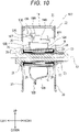
- a vehicle operating pedal apparatus 10B includes an operating pedal 12B.
- the operating pedal 12B is a hollow pedal formed by mating a pair of split halves together.
- a first latch hole 33 and a second latch hole 34 are formed in the pair of split halves that are apart from each other at the upper end of the operating pedal 12B.
- the vehicle operating pedal apparatus 10B is provided with an angle sensor 50B.
- the angle sensor 50B includes an IC holder 52B and a magnet holder 54B.
- a cuboid block is formed, protruding, on the upper part of the right surface of an IC holder 52B.
- An IC 56B is fixed to and exposed from the right side surface of the block.
- a snap-fit portion 68B is provided on the right surface of the magnet holder 54B.
- the snap-fit portion 68B has a protruding shape, and is inserted and locked into the second latch hole 34 of the operating pedal 12B.
- a magnet 58B and a snap-fit portion 69B are provided on the left surface of the magnet holder 54B.
- the magnet 58B is laid on the left surface of the magnet holder 54B in an arc shape with a radius substantially equal to the distance from the pivot center line 13 to the IC 56, and fixed to and exposed from the left surface of the magnet holder 54B.
- the snap-fit portion 69B has a protruding shape, and is inserted and locked into the first latch hole 33 of the operating pedal 12B.
- the magnet holder 54B is attached to the upper end of the operating pedal 12B in this manner. As a result, a part of the upper end surface of the operating pedal 12B is formed on the upper surface of the magnet holder 54B. Furthermore, the center of the arc of the magnet 58B provided on the left surface of the magnet holder 54B is located on the pivot center line 13.
- the IC 56B and the magnet 58B face each other in the left-and-right direction in a position that is closer to the boss 18 (that is, to the pivot bolt 26 and the collar 29) than the upper end surface of the operating pedal 12B.
- the magnet holder 54B is provided with a cover 70B.
- the cover 70B juts out upward and backward of the IC holder 52B from the upper and back edges of the left surface of the magnet holder 54B. Consequently, the cover 70B is disposed in an outer space that touches a gap across which the IC 56B and the magnet 58B face each other, along the upper and back edges of the left surface of the magnet holder 54B, and obscures the gap across which the IC 56B and the magnet 58B face each other.
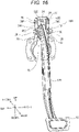
- a vehicle operating pedal apparatus 10C is provided with an angle sensor 50C.
- the angle sensor 50C includes an IC holder 52C and a magnet holder 54C.
- the IC holder 52C is substantially cuboid in shape.
- a snap-fit portion 60C is provided close to the screw hole 62 in the left surface of the IC holder 52C.
- a first mounting hole 31C into which the snap-fit portion 60C is inserted and locked is provided in the left support member 20, close to the second mounting hole 32 (refer to Fig. 2 ) and directly above the left pivot hole 21.
- An IC 56C is fixed to and exposed from the lower surface of the IC holder 52C.
- the IC holder 52C is attached to the left support member 20, which locates the IC 56C of the IC holder 52C in roughly the middle between the left support member 20 and the right support member 22 and above the operating pedal 12, and causes the IC 56C to face the middle of the upper end surface of the operating pedal 12 in the up-and-down direction.
- the magnet holder 54 includes a flat portion 55C and a curved portion 57C.
- the curved portion 57C of the magnet holder 54C is curved with a radius of curvature substantially equal to that of the upper end surface of the operating pedal 12.
- the magnet 58C is laid on and exposed from the upper surface of the curved portion 57C of the magnet holder 54C, on a center line passing through the middle in the left-and-right direction of the upper surface.
- the flat portion 55C of the magnet holder 54C extends downward from the left end of the curved portion 57C of the magnet holder 54C.
- the magnet holder 54C is attached to the upper end surface of the operating pedal 12.
- the magnet holder 54C is provided with two snap-fit portions 68C and 69C.
- the snap-fit portion 68C has a protruding shape, and is inserted and locked into the left surface of the operating pedal 12.
- the snap-fit portion 69C has a groove shape, and is fitted to the upper end of the operating pedal 12.
- the magnet holder 54C is attached to the upper end of the operating pedal 12 in this manner.
- the curved portion 57C of the magnet holder 54C covers the upper end surface of the operating pedal 12, and the flat portion 55C of the magnet holder 54C covers an area above the boss 18 on the left surface of the operating pedal 12.
- the magnet 58C provided on the upper surface of the curved portion 57C of the magnet holder 54C is located, in an arc shape that is equidistant from the pivot center line 13, on the upper end surface of the operating pedal 12, and faces the IC 56C in the up-and-down direction in roughly the middle between the left support member 20 and the right support member 22.
- the magnet holder 54C is provided with a cover 70C.
- the cover 70C juts out further to the right than the IC holder 52C from the right end surface of the curved portion 57C of the magnet holder 54C. Consequently, the cover 70C is disposed in an outer space that touches a gap across which the IC 56C and the magnet 58C face each other, along the right end surface of the curved portion 57C of the magnet holder 54C, and obscures the right side of the gap across which the IC 56C and the magnet 58C face each other.
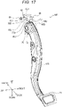
- a vehicle operating pedal apparatus 10D includes an operating pedal 12D.
- the operating pedal 12D is a hollow pedal formed by mating a pair of split halves together.
- the vehicle operating pedal apparatus 10D is provided with an angle sensor 50D.
- the angle sensor 50D includes an IC holder 52D and a magnet holder 54D.
- the IC holder 52D forms a three-dimensional L shape in plan view.
- a snap-fit portion 60D is provided close to the screw hole 62 in the left surface of the ID holder 52D.
- a first mounting hole 31D into which the snap-fit portion 60D is inserted and locked is provided in the left support member 20, close to the second mounting hole 32 (refer to Fig. 2 ) and directly above the left pivot hole 21.
- An IC 56D is fixed to and exposed from the lower surface of the IC holder 52D.
- the IC holder 52D is attached to the left support member 20, which locates the IC 56D of the IC holder 52D in roughly the middle between the left support member 20 and the right support member 22 and above the operating pedal 12D, and causes the IC 56D to face the middle of the upper end surface of the operating pedal 12D in the up-and-down direction.
- the magnet holder 54D includes a flat portion 55D and a curved portion 57D.
- the curved portion 57D of the magnet holder 54D is curved with a radius of curvature substantially equal to that of the upper end surface of the operating pedal 12.
- a magnet 58D is laid on and exposed from the upper end surface of the curved portion 57D of the magnet holder 54D, on a center line passing through the middle in the left-and-right direction of the upper surface.
- the flat portion 55D of the magnet holder 54D extends downward from the left end of the curved portion 57D of the magnet holder 54D.
- the magnet holder 54D is attached to the pair of split halves that are apart from each other at the upper end of the operating pedal 12D.
- the magnet holder 54D is provided with snap-fit portions 68D and 69D.
- the snap-fit portion 68D which is one of the snap-fit portions, has a protruding shape, is provided on the left surface of the flat portion 55D of the magnet holder 54D, and is inserted and locked into a latch hole 15 in the left surface (the left split half) of the operating pedal 12D.
- Two pairs of the snap-fit portion 68D and the latch hole 15 are provided.
- the other snap-fit portion 69D has a groove shape, provided in the lower surface of the curved portion 57D of the magnet holder 54D, and is fitted to the upper end of the right surface (the right split half) of the operating pedal 12D.
- the magnet holder 54D is attached to the upper end of the operating pedal 12D in this manner. As a result, a part of the upper end surface of the operating pedal 12D is formed by the upper surface of the magnet holder 54D.
- the magnet 58D provided on the upper surface of the curved portion 57D of the magnet holder 54D is located, in an arc shape that is equidistant from the pivot center line 13, on the upper end surface of the operating pedal 12D, and faces the IC 56D in the up-and-down direction in roughly the middle between the left support member 20 and the right support member 22.
- the magnet holder 54D is provided with a cover 70D.
- the cover 70D juts out further to the right than the IC holder 52D along the right side of the magnet 58D on the upper surface of the curved portion 57D of the magnet holder 54D. Consequently, the cover 70D is disposed in an outer space that touches a gap across which the IC 56D and the magnet 58D face each other, along the right side of the IC holder 52D, and obscures the right side of the gap across which the IC 56D and the magnet 58D face each other.
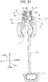
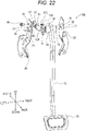
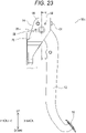
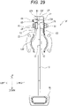
- a vehicle operating pedal apparatus 10E As illustrated in Figs. 21 to 25 , a vehicle operating pedal apparatus 10E according to a fifth embodiment is provided with an angle sensor 50E.
- the angle sensor 50E includes the IC holder 52 and a magnet holder 54E.
- the magnet holder 54E forms a substantially annular shape including a circular opening 71.
- a magnet 58E is laid in an arc shape formed by the center of the circular opening 71 and a radius substantially equal to the distance from the pivot center line 13 to the IC 56, and is fixed and exposed above the circular opening 71.
- the magnet holder 54E is fitted on the boss 18 on the left side of the upper end of the operating pedal 12.
- the above circular opening 71 is formed in the magnet holder 54E.
- the boss 18 is fitted into the circular opening 71.
- the magnet holder 54E is attached to the upper end of the operating pedal 12 in this manner.
- the magnet holder 54E covers around the boss 18 on the left surface of the operating pedal 12.
- the center of the circular opening 71 agrees with the center of the boss 18. Consequently, the center of the arc of the magnet 58E provided on the left surface of the magnet holder 54E is located on the pivot center line 13. Consequently, the magnet 58E of the magnet holder 54E faces the IC 56 of the IC holder 52 in the left-and-right direction above the boss 18 on the left side of the operating pedal 12.
- the IC 56 and the magnet 58E face each other in a position that is closer to the boss 18 (that is, to the pivot bolt 26 and the collar 29) than the upper end surface of the operating pedal 12.
- the left support member 20 is provided with a left hole 35 further to the front than the left pivot hole 21.
- the right support member 22 is provided with a right hole 36 further to the front than the right pivot hole 23.
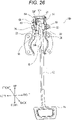
- a vehicle operating pedal apparatus 10F is provided with an angle sensor 50F.
- the angle sensor 50F includes an IC holder 52F and a magnet holder 54F.
- the IC holder 52F is a substantially cuboid in shape.
- An IC 56F is fixed to and exposed from the lower surface of the IC holder 52F.
- the IC holder 52F is attached to the left support member 20, which locates the IC 56F of the IC holder 52F in substantially the middle between the left support member 20 and the operating pedal 12 and above the boss 18 on the left side of the operating pedal 12, and causes the IC 56F to face in the up-and-down direction the middle in the left-and-right direction of the boss 18 on the left side of the operating pedal 12.
- the magnet holder 54F forms an annular shape. A distance from the center to the outer side surface of the annular ring of the magnet holder 54F (that is, the radius of the magnet holder 54F) is slightly shorter than a distance from the pivot center line 13 to the IC 56F.
- a magnet 58F is laid on and exposed from the upper part of the outer side surface of the magnet holder 54F on a center line passing through the middle in the left-and-right direction of the magnet holder 54F.
- a distance from the center of the annular ring of the magnet holder 54F to the exposed surface of the magnet 58F is slightly shorter than the distance from the pivot center line 13 to the IC 56F.
- the inside diameter of the magnet holder 54F is substantially equal to the outside diameter of the boss 18 on the left side of the operating pedal 12.
- the annular magnet holder 54F is fitted onto the boss 18 on the left side of the operating pedal 12, on the left side of the upper end of the operating pedal 12.
- the upper part of the side surface of the boss 18 on the left side of the operating pedal 12 is provided with a recessed snap-fit portion 17 along a center line passing through the middle in the left-and-right direction of the boss 18.
- the upper part of the inner side surface of the annular magnet holder 54F is provided with a protruding snap-fit portion 68F along the center line passing through the middle in the left-and-right direction of the magnet holder 54F.
- the snap-fit portion 68F of the boss 18 on the left side of the operating pedal 12 is fitted into the snap-fit portion 17 of the annular magnet holder 54F.
- the magnet holder 54F is attached to the upper end of the operating pedal 12 in this manner, which locates the magnet 58F provided on the outer side surface of the annular magnet holder 54F, in an arc shape that is equidistant from the pivot center line 13, in a position that is closer to the boss 18 (that is, to the pivot bolt 26 and the collar 29) than the upper end surface of the operating pedal 12, and causes the magnet 58F to face the IC 56F of the IC holder 52F in the up-and-down direction in roughly the middle between the left support member 20 and the operating pedal 12.
- the IC 56 of the angle sensor 50 is provided between the left support member 20 and the right support member 22 (that is, on the inner side), and the magnet 58 of the angle sensor 50 is provided at the upper end of the operating pedal 12, facing the IC 56.
- Such a configuration allows the space for mounting the angle sensor 50 that detects the angle of rotation of the operating pedal 12 to be made compact in the vehicle operating pedal apparatus 10 according to the embodiments.
- the IC 56 and the magnet 58 face each other in the position that is closer to the boss 18 (that is, to the pivot bolt 26 and the collar 29) than the upper end surface of the operating pedal 12. Consequently, the space for mounting the angle sensor 50 can be made more compact in the vehicle operating pedal apparatus 10A according to the first embodiment.
- the same point is valid with regard to the vehicle operating pedal apparatus 10B according to the second embodiment, the vehicle operating pedal apparatus 10E according to the fifth embodiment, and the vehicle operating pedal apparatus 10F according to the sixth embodiment.
- the magnet 58C is provided, in the arc shape that is equidistant from the pivot center line 13 of the operating pedal 12, on the upper end surface of the operating pedal 12. Consequently, the detection accuracy of the IC 56 is improved in the vehicle operating pedal apparatus 10C according to the third embodiment. The same point is valid with regard to the vehicle operating pedal apparatus 10D according to the fourth embodiment.
- the magnet 58 of the vehicle operating pedal apparatus 10A according to the first embodiment is provided, in the arc shape that is equidistant from the pivot center line 13 of the operating pedal 12, in the position that is closer to the boss 18 (that is, to the pivot bolt 26 and the collar 29) than the upper end surface of the operating pedal 12.
- the detection accuracy of the IC 56 is improved also in the vehicle operating pedal apparatus 10A according to the first embodiment.
- the same point is valid with regard to the vehicle operating pedal apparatus 10B according to the second embodiment, the vehicle operating pedal apparatus 10E according to the fifth embodiment, and the vehicle operating pedal apparatus 10F according to the sixth embodiment.
- the cover 70 that juts out from the magnet holder 54, and is disposed in the outer space that touches the gap across which the IC 56 and the magnet 58 face each other obscures the gap. Consequently, the prevention of the entry of foreign matter into the detection space of the angle sensor 50 is encouraged.
- the vehicle operating pedal apparatus 10B according to the second embodiment, the vehicle operating pedal apparatus 10C according to the third embodiment, and the vehicle operating pedal apparatus 10D according to the fourth embodiment is valid with regard to the vehicle operating pedal apparatus 10B according to the second embodiment, the vehicle operating pedal apparatus 10C according to the third embodiment, and the vehicle operating pedal apparatus 10D according to the fourth embodiment.
- the cover 70 that juts out from the magnet holder 54 obscures, from the back side of the vehicle, the back side of the gap across which the IC 56 and the magnet 58 face each other, in addition to the upper side of the gap across which the IC 56 and the magnet 58 face each other. Consequently, the prevention of the entry of foreign matter into the detection space of the angle sensor 50 is encouraged. The same point is valid with regard to the vehicle operating pedal apparatus 10B according to the second embodiment.
- the upper end surface of the operating pedal 12 is an example of a "side surface at one end of an operating pedal.”
- the left pivot hole 21 and the right pivot hole 23 are examples of “holes provided in support members.”
- the pivot bolt 26 and the collar 29 are examples of "pivot axis members.”
- the left support member 20 and the right support member 22 are an example of a "pair of support members.”
- the IC holder 52 is an example of a "device holder.”
- the IC 56 is an example of a "Hall device.”
- the present invention is not limited to the above embodiments, and can be modified in various manners within a scope that does not depart from a gist thereof.
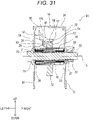
- the cover 70 according to the first embodiment may be replaced with a cover 170 as illustrated in Fig. 31 .
- the cover 170 juts out upward and backward of the IC holder 52 from the upper and back edges of the flat portion 55 of the magnet holder 54 that has a fan shape in side view. Consequently, the cover 170 is disposed in an outer space that touches the gap across which the IC 56 and the magnet 58 face each other, along the upper and back edges of the flat portion 55 of the magnet holder 54 that has a fan shape in side view, and obscures the gap across which the IC 56 and the magnet 58 face each other. Furthermore, the cover 170 inclines upward toward the magnet holder 54.
- the upper surface of the cover 170 that faces the outer space that touches the gap across which the IC 56 and the magnet 58 face each other inclines downward from the distal end toward the proximal end (near the flat portion 55 of the magnet holder 54).
- the cover 70 according to the first embodiment may be replaced with a cover 270 as illustrated in Fig. 32 .
- the cover 270 juts out upward and backward of the magnet holder 54 from the upper and back edges of the upper surface of the IC holder 52. Consequently, the cover 270 is disposed in an outer space that touches the gap across which the IC 56 and the magnet 58 face each other, along the upper and back edges of the flat portion 55 of the magnet holder 54 that has a fan shape in side view, and obscures the gap across which the IC 56 and the magnet 58 face each other.
- the cover 70 according to the first embodiment may be replaced with a cover 370 as illustrated in Fig. 33 .
- the cover 370 juts out upward and backward of the magnet holder 54 from the upper and back edges of the upper surface of the ID holder 52, and reaches further to the right than the magnet holder 54. Consequently, the cover 370 is disposed in an outer space that touches the gap across which the IC 56 and the magnet 58 face each other, along the upper and back edges of the flat portion 55 of the magnet holder 54 that has a fan shape in side view, and obscures the gap across which the IC 56 and the magnet 58 face each other. Furthermore, the distal end of the cover 370 inclines downward toward the edge (the right).
- the cover 70C according to the third embodiment may be replaced with a cover 470 as illustrated in Fig. 34 .
- the cover 470 juts out rightward of the IC holder 52C from the right end surface of the curved portion 57C of the magnet holder 54C as in the above cover 70C. Consequently, the cover 470 is disposed in an outer space that touches the gap across which the IC 56C and the magnet 58C face each other, along the right end surface of the curved portion 57C of the magnet holder 54C, and obscures the right side of the gap across which the IC 56C and the magnet 58C face each other. Furthermore, the cover 470 inclines downward from the distal end toward the proximal end (near the curved portion 57C of the magnet holder 54C).
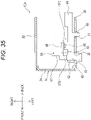
- the cover 70 according to the first embodiment may be replaced with a cover 570 as illustrated in Fig. 35 .
- the cover 570 juts out toward the right surface of the IC holder 52 from the front edge of the flat portion 55 of the magnet holder 54 that has a fan shape in side view, in addition to the upper and back edges of the flat portion 55 of the magnet holder 54 that has a fan shape in side view. Consequently, the cover 570 is disposed in an outer space that touches the gap across which the IC 56 and the magnet 58 face each other, along the upper, back, and front edges of the flat portion 55 of the magnet holder 54 that has a fan shape in side view, and obscures the gap across which the IC 56 and the magnet 58 face each other.
- the covers 170, 270, 370, 470, and 570 also encourage the prevention of the entry of foreign matter into the detection space of the angle sensor 50 as in the cover 70 according to the first embodiment.
- the cover 570 obscures, from the front side of the vehicle, the front side of the gap across which the IC 56 and the magnet 58 face each other, in addition to the upper and back sides of the gap across which the IC 56 and the magnet 58 face each other. Consequently, the prevention of the entry of foreign matter into the detection space of the angle sensor 50 is encouraged.
- the upper surface of the cover 170 that faces the outer space of the gap across which the IC 56 and the magnet 58 face each other inclines downward from the distal end toward the proximal end (near the flat portion 55 of the magnet holder 54), which prevents the build-up of foreign matter.
- the cover 470 according to the modification illustrated in Fig. 34 is valid with regard to the cover 470 according to the modification illustrated in Fig. 34 .
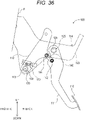
- the present invention may be carried out in a vehicle operating pedal apparatus 100 including what is called a link-type pedal mechanism.
- the vehicle operating pedal apparatus 100 includes a first operating pedal 111, a second operating pedal 112, and a pair of support members 114, and is mounted on a vehicle.
- the pair of support members 114 faces each other, spaced a predetermined distance away from each other in the left-and-right direction, and is fixed to the dash panel P.
- the support member on the left side (hereinafter referred to as the "left support member") 120 of the pair of support members 114 is indicated by a chain double-dashed line, and the support member on the right side is not illustrated.
- a fist shaft 125 is placed at the upper end of the first operating pedal 111.
- the first shaft 125 includes a pivot bolt 126, pivot holes provided in the pair of support members 114, and a tubular boss, collar, bushing, nut, and the like that are provided to the first operating pedal 111 as in the pivot support structure of the operating pedal 12 according to the first embodiment. Consequently, the first shaft 125 supports the first operating pedal 111 between the pair of support members 114 in such a manner that the first operating pedal 111 is pivotable.
- a tread 116 is provided at the lower end of the first operating pedal 111. Therefore, the tread 116 can pivot relative to the pair of support members 114.
- a second shaft 138 is placed at the lower end of the second operating pedal 112.
- the second shaft 138 includes a pivot bolt 139, pivot holes provided in the pair of support members 114, and a tubular boss, collar, bushing, nut, and the like that are provided to the second operating pedal 112 as in the pivot support structure of the operating pedal 12 according to the first embodiment. Consequently, the second shaft 138 supports the second operating pedal 112 between the pair of support members 114 in such a manner that the second operating pedal 112 is pivotable.
- a point indicated by a reference sign 113 indicates a pivot center line that is the pivot of the rotation of the second operating pedal 112 in a length direction of the pivot center line (the left-and-right direction).
- the midpoint of the second operating pedal 112 is coupled to the first operating pedal 111 by a link member 140 between the upper end and the lower end of the first operating pedal 111.
- the link member 140 includes a first link pin 142 and a second link pin 144.
- the first link pin 142 is placed in the back part of the link member 140, and couples the link member 140 and the first operating pedal 111.
- the first link pin 142 supports the link member 140 in such a manner that the link member 140 is pivotable relative to the first operating pedal 111.
- the second link pin 144 is placed in the front part of the link member 140 and couples the link member 140 and the second operating pedal 112.
- the second link pin 144 supports the link member 140 in such a manner that the link member 140 is pivotable relative to the second operating pedal 112.
- the first operating pedal 111 pivots on the first shaft 125.
- Such pivotal rotation of the first operating pedal 111 is transmitted to the second operating pedal 112 via the link member 140. Consequently, the second operating pedal 112 pivots on the second shaft 138.
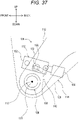
- the vehicle operating pedal apparatus 100 is provided with an angle sensor 150.
- the angle sensor 150 detects the angle of rotation of the second operating pedal 112 that pivots on the pivot center line 113. As illustrated in Fig. 37 , the angle sensor 150 includes an IC holder 152 and a magnet 158. An IC 156 for detecting the magnetic field of a magnet 158 is fixed to and exposed from the IC holder 152.
- the IC holder 152 is substantially cuboid in shape.
- the left surface of the IC holder 152 is provided with, for example, a protruding snap-fit portion 160.
- the back surface of the IC holder 152 is provided with a connector 164.
- a cuboid block 153 is formed, protruding, on the lower part of the right surface of the IC holder 152.
- the IC 156 is placed on the right side surface of the block.
- the IC holder 152 is attached to the left support member 120 with the left surface of the IC holder 152 in contact with the inner surface (right surface) of the left support member 120. Hence, the snap-fit portion 160 is inserted from the right side of a mounting hole provided in the left support member 120, and locked into the mounting hole.
- the IC holder 152 is attached to the inner surface (right surface) of the left support member 120 in this manner, which places the IC 156 of the IC holder 152 between the pair of support members 114 (that is, on the inner side).
- the magnet 158 is fixed to and exposed from the left surface of the lower end of the second operating pedal 112 above the second shaft 138 (that is, the boss of the second operating pedal 112).
- the magnet 158 is placed in an arc shape with a radius substantially equal to a distance from the pivot center line 113 to the IC 156. Furthermore, the center of the arc of the magnet 158 is located on the pivot center line 113. Consequently, the magnet 158 faces the IC 156 of the IC holder 152 in the left-and-right direction in an area above the second shaft 138 on the left surface of the lower end of the second operating pedal 112. In other words, the IC 156 and the magnet 158 face each other in a position that is closer to the pivot bolt 139 of the second shaft 138 than the lower end surface of the second operating pedal 112.
- the IC 156 of the angle sensor 150 is provided between the pair of support members 114 (that is, on the inner side), and the magnet 158 of the angle sensor 150 is provided at the lower end of the second operating pedal 112, facing the IC 156.
- Such a configuration allows the space for mounting the angle sensor 150 that detects the angle of rotation of the second operating pedal 112 to be made compact in the vehicle operating pedal apparatus 100.
- the IC 156 and the magnet 158 face each other in the position that is closer to the pivot bolt 139 of the second shaft 138 than the lower end surface of the second operating pedal 112. Consequently, the space for mounting the angle sensor 150 can be made more compact in the vehicle operating pedal apparatus 100.
- the second operating pedal 112 is an example of an "operating pedal.”
- the lower end surface of the second operating pedal 112 is an example of a "side surface at one end of an operating pedal.”
- the pivot hole provided in the support member 114 is an example of a "hole provided in a support member.”
- the pivot bolt 139 of the second shaft 138 is an example of a "pivot axis member.”
- the IC 156 is an example of a "Hall device.”
- a seventh embodiment is described below with reference to Figs. 38 to 42 .
- An alphabet letter "G" added to reference signs indicates the seventh embodiment in Figs. 38 to 42 .
- the directions in the drawings are as described in the drawings. However, in the side view of Fig. 40 , the direction into the page is rightward, and the direction out of the page is leftward. In other words, the direction orthogonal to the page in Fig. 40 is the left-and-right direction. Moreover, in the front view of Fig. 41 , the direction into the page is forward, and the direction out of the page is backward. In other words, the direction orthogonal to the page in Fig. 41 is the front-and-back direction. The same points are valid with regard to the cross-sectional view of Fig. 42 .
- a vehicle operating pedal apparatus 10G is provided with an angle sensor 50G.
- the angle sensor 50G includes an IC holder 52G and the magnet holder 54.
- the IC holder 52G is substantially cuboid in shape, and the back surface of the IC holder 52G is provided with the connector 64.
- a snap-fit portion 60G is provided close to the connector 64 on the right surface of the IC holder 52G.
- a screw hole 62G is provided to a place at a corner where the front and upper surfaces of the IC holder 52G intersect, a place projecting in such a manner as to extend off the corner, and penetrates the place along the left-and-right direction.
- a second mounting hole 32G into which the mounting bolt 66 protruding from the screw hole 62G is screwed is provided in the middle between the front part and the upper part relative to the first mounting hole 31 into which the snap-fit portion 60G is inserted and locked.
- a female thread is formed in each of the screw hole 62G of the IC holder 52G and the second mounting hole 32G of the left support member 20.
- a female thread may not be formed in the screw hole 62G of the IC holder 52G.
- a cuboid protrusion 72 is provided between the snap-fit portion 60G and the screw hole 62G on the right surface of the IC holder 52G.
- the protrusion 72 protrudes to the right from the right surface of the IC holder 52G.
- An IC 56G is fixed inside the protrusion 72.
- a part of the IC 56G is exposed in a window 74 provided in the right side surface of the protrusion 72.
- the IC holder 52G is attached to the left support member 20 with the right surface (excluding the protrusion 72) of the IC holder 52G in contact with the outer surface (left surface) of the left support member 20.
- the left support member 20 is provided with an insertion hole 37 between the first mounting hole 31 and the second mounting hole 32G.
- the protrusion 72 of the IC holder 52G is inserted into the insertion hole 37 from the left side of the insertion hole 37. Consequently, the protrusion 72 of the IC holder 52G protrudes to the right from the right side of the insertion hole 37 through the insertion hole 37.
- the snap-fit portion 60G of the IC holder 52G is inserted and locked into the first mounting hole 31 from the left side of the first mounting hole 31.
- the mounting bolt 66 is screwed into the screw hole 62G of the IC holder 52G from the left side of the screw hole 62G. Consequently, the mounting bolt 66 protrudes to the right from the right side of the screw hole 62G through the screw hole 62G of the IC holder 52G.
- the protruding portion of the mounting bolt 66 is screwed into the second mounting hole 32G of the left support member 20 from the left side of the second mounting hole 32G.
- the magnet holder 54 is similar to that of the first embodiment, excluding a cover 70G.
- the cover 70G does not obscure a gap across which the IC 56G and the magnet 58 face each other, unlike the first embodiment.
- the IC holder 52G is attached to the outer surface (left surface) of the left support member 20 in this manner, which places a part (that is, the right half) of the IC 56G of the IC holder 52G between the left support member 20 and the right support member 22 (that is, on the inner side) in a position further to the right than the insertion hole 37 of the left support member 20.
- the remaining portion (that is, the left half) of the IC 56G of the IC holder 52G is placed in the insertion hole 37 of the left support member 20. Consequently, the IC 56G of the IC holder 52G faces the magnet 58 of the magnet holder 54 in the left-and-right direction in an area above the boss 18 on the left surface of the operating pedal 12.
- the entire IC 56G of the IC holder 52G may be placed between the left support member 20 and the right support member 22 (that is, on the inner side) with the protrusion 72 of the IC holder 52G in the insertion hole 37 of the left support member 20.
- the IC 56G of the angle sensor 50G is provided between the left support member 20 and the right support member 22 (that is, on the inner side), and the magnet 58 of the angle sensor 50G is provide at the upper end of the operating pedal 12, facing the IC 56G.
- Such a configuration allows the space for mounting the angle sensor 50G that detects the angle of rotation of the operating pedal 12 to be made compact in the vehicle operating pedal apparatus 10G according to the seventh embodiment.
- the IC 56G and the magnet 58 face each other in a position that is closer to the boss 18 (that is, to the pivot bolt 26 and the collar 29) than the upper end surface of the operating pedal 12. Consequently, the space for mounting the angle sensor 50G can be made more compact in the vehicle operating pedal apparatus 10G according to the seventh embodiment.
- the magnet 58 of the vehicle operating pedal apparatus 10G according to the seventh embodiment is provided, in an arc shape that is equidistant from the pivot center line 13 of the operating pedal 12, in the position that is closer to the boss 18 (that is, to the pivot bolt 26 and the collar 29) than the upper end surface of the operating pedal 12 as in the first embodiment.
- the detection accuracy of the IC 56G is improved also in the vehicle operating pedal apparatus 10G according to the seventh embodiment.
- the upper end surface of the operating pedal 12 is an example of a "side surface at one end of an operating pedal.”
- the left pivot hole 21 and the right pivot hole 23 are examples of “holes provided in support members.”
- the pivot bolt 26 and the collar 29 are examples of "pivot axis members.”
- the left support member 20 and the right support member 22 are an example of a "pair of support members.”
- the IC holder 52G is an example of a “device holder.”
- the IC 56G is an example of a "Hall device.”
Landscapes
- Engineering & Computer Science (AREA)
- Physics & Mathematics (AREA)
- General Physics & Mathematics (AREA)
- Transportation (AREA)
- Mechanical Engineering (AREA)
- Automation & Control Theory (AREA)
- Chemical & Material Sciences (AREA)
- Combustion & Propulsion (AREA)
- Mechanical Control Devices (AREA)
Abstract
Description
- The present invention relates to a vehicle operating pedal apparatus including an angle sensor that detects the angle of rotation of an operating pedal.
- Various technologies related to the above vehicle operating pedal apparatus have conventionally been proposed.
- For example, a technology described in Patent Literature 1 below is an operation amount detection apparatus, and includes a stroke sensor that detects the stroke of the tread of a pedal section (a pedal stroke). The stroke sensor includes a sensor body, and a sensor arm (a part of the sensor body) provided in such a manner as to be pivotable on a sensor pivot axis relative to the sensor body. The sensor arm has a pair of bifurcations that are two branches divided and extend substantially parallel. A guide groove that extends radially outward from the sensor pivot axis and is formed in a straight line is provided between the pair of bifurcations. A pin fixed to the pedal arm is slidably engaged in the guide groove. The pedal arm has a substantially arc shape, is fixed to the upper end of the pedal section, and pivots integrally with the pedal section. The pin is fixed to the upper end of the pedal arm, and protrudes in a direction substantially orthogonal to the pedal arm extension direction (toward the stroke sensor).
- PATENT LITERATURE 1:
JP-A-2014-21791 - The operation amount detection apparatus described in Patent Literature 1 above is provided to the pedal section for a vehicle and therefore a compact apparatus is desired.
- Hence, the present invention has been made, considering the above point, and an objective thereof is to provide a vehicle operating pedal apparatus having a compact space for mounting an angle sensor that detects the angle of rotation of an operating pedal.
- In order to achieve the above described objective, the invention according to claim 1 is a vehicle operating pedal apparatus which includes: a pair of support members fixed to a vehicle member, the pair of support members facing each other; an operating pedal provided at one end with a tubular boss for the pedal, the operating pedal being supported between the pair of support members in such a manner as to be pivotable on a pivot axis member that is inserted into holes provided in the support members and the boss; and an angle sensor configured to detect the angle of rotation of the operating pedal. The angle sensor includes: a Hall device provided on an inner side between the pair of support members; and a magnet provided at the one end of the operating pedal, facing the Hall device, the magnet being configured to detect the magnetic field of the Hall device.
- The invention according to claim 2 is the vehicle operating pedal apparatus according to claim 1, in which the Hall device and the magnet face each other in a position that is closer to the pivot axis member than a side surface at the one end of the operating pedal.
- The invention according to claim 3 is the vehicle operating pedal apparatus according to claim 1, in which the magnet is placed, in an arc shape that is equidistant from a pivot center line of the operating pedal, on a side surface at the one end of the operating pedal.
- The invention according to claim 4 is the vehicle operating pedal apparatus according to any one of claims 1 to 3, including: a device holder to which the Hall device is fixed, the device holder being attached to the support member; a magnet holder to which the magnet is fixed, the magnet holder being attached to the one end of the operating pedal; and a cover jutting out from the device holder or the magnet holder, the cover being disposed in at least part of a gap across which the Hall device and the magnet face each other, and of an outer space.
- The invention according to claim 5 is the vehicle operating pedal apparatus according to claim 4, in which the cover is provided to the device holder.
- The invention according to claim 6 is the vehicle operating pedal apparatus according to claim 4, in which the cover is provided to the magnet holder.
- The invention according to claim 7 is the vehicle operating pedal apparatus according to any one of claims 4 to 6, in which the cover is provided to at least one of the upper side of the gap, the front side of a vehicle, or the back side of the vehicle.
- The invention according to claim 8 is the vehicle operating pedal apparatus according to any one of claims 4 to 7, in which the cover has a surface facing the outer space, the surface inclining downward from a distal end toward a proximal end thereof.
- The invention according to claim 9 is the vehicle operating pedal apparatus according to claim 1 or 2, further including: a device holder including a protrusion to which the Hall device is fixed, the device holder being attached to the support member from the outside of the support member, wherein the protrusion of the device holder is inserted from the outer side to the inner side of the support member through an insertion hole of the support member to provide the Hall device on the inner side between the pair of support members.
- A vehicle operating pedal apparatus of the present invention has a compact space for mounting an angle sensor that detects the angle of rotation of an operating pedal.
-
-
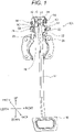
Fig. 1 is a perspective view illustrating a vehicle operating pedal apparatus according to a first embodiment. -
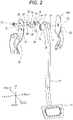
Fig. 2 is an exploded perspective view illustrating the vehicle operating pedal apparatus. -
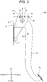
Fig. 3 is a side view illustrating the vehicle operating pedal apparatus. -
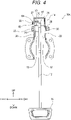
Fig. 4 is a front view illustrating the vehicle operating pedal apparatus. -
Fig. 5 is a diagram illustrating the vehicle operating pedal apparatus in a cross-section taken along line I-I inFig. 3 . -
Fig. 6 is a perspective view illustrating a vehicle operating pedal apparatus according to a second embodiment. -
Fig. 7 is an exploded perspective view illustrating the vehicle operating pedal apparatus. -
Fig. 8 is a side view illustrating the vehicle operating pedal apparatus. -
Fig. 9 is a front view illustrating the vehicle operating pedal apparatus. -
Fig. 10 is a diagram illustrating the vehicle operating pedal apparatus in a cross-section taken along line II-II inFig. 8 . -
Fig. 11 is a perspective view illustrating a vehicle operating pedal apparatus according to a third embodiment. -
Fig. 12 is an exploded perspective view illustrating the vehicle operating pedal apparatus. -
Fig. 13 is a side view illustrating the vehicle operating pedal apparatus. -
Fig. 14 is a front view illustrating the vehicle operating pedal apparatus. -
Fig. 15 is a diagram illustrating the vehicle operating pedal apparatus in a cross-section taken along line III-III inFig. 13 . -
Fig. 16 is a perspective view illustrating a vehicle operating pedal apparatus according to a fourth embodiment. -
Fig. 17 is an exploded perspective view illustrating the vehicle operating pedal apparatus. -
Fig. 18 is a side view illustrating the vehicle operating pedal apparatus. -
Fig. 19 is a front view illustrating the vehicle operating pedal apparatus. -
Fig. 20 is a diagram illustrating the vehicle operating pedal apparatus in a cross-section taken along line IV-IV inFig. 18 . -
Fig. 21 is a perspective view illustrating a vehicle operating pedal apparatus according to a fifth embodiment. -
Fig. 22 is an exploded perspective view illustrating the vehicle operating pedal apparatus. -
Fig. 23 is a side view illustrating the vehicle operating pedal apparatus. -
Fig. 24 is a front view illustrating the vehicle operating pedal apparatus. -
Fig. 25 is a diagram illustrating the vehicle operating pedal apparatus in a cross-section taken along line V-V inFig. 23 . -
Fig. 26 is a perspective view illustrating a vehicle operating pedal apparatus according to a sixth embodiment. -
Fig. 27 is an exploded perspective view illustrating the vehicle operating pedal apparatus. -
Fig. 28 is a side view illustrating the vehicle operating pedal apparatus. -
Fig. 29 is a front view illustrating the vehicle operating pedal apparatus. -
Fig. 30 is a diagram illustrating the vehicle operating pedal apparatus in a cross-section taken along line VI-VI inFig. 28 . -
Fig. 31 is a diagram illustrating a first modification of the vehicle operating pedal apparatus according to the first embodiment in a cross-section taken along line I-I inFig. 3 . -
Fig. 32 is a diagram illustrating a second modification of the vehicle operating pedal apparatus in a cross-section taken along line I-I inFig. 3 . -
Fig. 33 is a diagram illustrating a third modification of the vehicle operating pedal apparatus in a cross-section taken along line I-I inFig. 3 . -
Fig. 34 is a diagram illustrating a modification of the vehicle operating pedal apparatus according to the third embodiment in a cross-section taken along line III-III inFig. 13 . -
Fig. 35 is a diagram illustrating a fourth modification of the vehicle operating pedal apparatus according to the first embodiment in a cross-section taken along line VII-VII inFig. 3 . -
Fig. 36 is a side view illustrating a modification of the vehicle operating pedal apparatus. -
Fig. 37 is an enlarged side view illustrating a part of the modification. -
Fig. 38 is a perspective view illustrating a vehicle operating pedal apparatus according to a seventh embodiment. -
Fig. 39 is an exploded perspective view illustrating the vehicle operating pedal apparatus. -
Fig. 40 is a side view illustrating the vehicle operating pedal apparatus. -
Fig. 41 is a front view illustrating the vehicle operating pedal apparatus. -
Fig. 42 is a diagram illustrating the vehicle operating pedal apparatus in a cross-section taken along line VIII-VIII inFig. 40 . - A vehicle operating pedal apparatus according to the present invention is described hereinafter on the basis of materialized embodiments thereof with reference to the drawings. In the embodiments, the vehicle operating pedal apparatus according to the present invention is attached to a vehicle to be used as a brake pedal. However, the vehicle operating pedal apparatus according to the present invention may be used as a vehicle pedal (for example, the accelerator pedal or clutch pedal) other than the brake pedal.
- The drawings used for the following description are drawn, omitting part of a basic configuration. The dimension ratio and the like of each portion drawn are not necessarily correct. The same reference signs are assigned to parts having correspondences in the embodiments. Furthermore, in terms of alphabet letters added to the reference signs, "A" indicates a first embodiment, "B" indicates a second embodiment, "C" indicates a third embodiment, "D" indicates a fourth embodiment, "E" indicates a fifth embodiment, and "F" indicates a sixth embodiment. However, the same reference signs without the above added alphabet letters are assigned to parts that are substantially common among the embodiments. In the second and subsequent embodiments, a detailed description is omitted. Moreover, when parts and the like are collectively mentioned without distinguishing the embodiments, a description is given, using the reference signs without the above added alphabet letters.
- Moreover, the directions in the drawings are as described in the drawings. However, in the side views of
Figs. 3 ,8 ,13 ,18 ,23 ,28 ,36 , and37 , the direction into the page is rightward, and the direction out of the page is leftward. In other words, the direction orthogonal to the page inFigs. 3 ,8 ,13 ,18 ,23 ,28 ,36 , and37 is the left-and-right direction. - Moreover, in the front views of
Figs. 4 ,9 ,14 ,19 ,24 , and29 , the direction into the page is forward, and the direction out of the page is backward. In other words, the direction orthogonal to the page inFigs. 4 ,9 ,14 ,19 ,24 , and29 is the front-and-back direction. The same points are valid with regard to the cross-sectional views ofFigs. 5 ,10 ,15 ,20 ,25 , and30 to 34 . - Moreover, in the cross-sectional view of
Fig. 35 , the direction into the page is downward, and the direction out of the page is upward. In other words, the direction orthogonal to the page inFig. 35 is the up-and-down direction. - As illustrated in
Figs. 1 to 5 , a vehicle operatingpedal apparatus 10A according to a first embodiment includes an operatingpedal 12 and asupport member 14, and is mounted on a vehicle. A steppingpart 16 is provided at the lower end of the operatingpedal 12. Atubular boss 18 is fixed to the upper end of the operatingpedal 12, penetrating the upper end. Acollar 29 on which a pair ofbushings 28 is fitted at the left and right ends of thecollar 29 is fitted in theboss 18. Consequently, the tubular portions of thebushings 28 are placed between theboss 18 and thecollar 29. - The
support member 14 includes aleft support member 20, aright support member 22, and an uppermiddle support member 24, and is fixed to the vehicle (for example, a dash panel P). Theleft support member 20 and theright support member 22 are coupled to the uppermiddle support member 24 from the front ends across the upper ends of theleft support member 20 and theright support member 22, and face each other in the left-and-right direction. Theleft support member 20 is provided with aleft pivot hole 21. Theright support member 22 is provided with aright pivot hole 23. Theboss 18 of the operatingpedal 12 is disposed between theleft pivot hole 21 and theright pivot hole 23 to cause theleft pivot hole 21 and theright pivot hole 23 to communicate with each other in the left-and-right direction via thecollar 29 in theboss 18. With the pivot holes communicating with each other, apivot bolt 26 is passed through thecollar 29 in theboss 18 from theleft pivot hole 21 to theright pivot hole 23. - The head of the
pivot bolt 26 is in contact with theleft support member 20 while the end of thepivot bolt 26 protrudes to the right from theright support member 22. The protruding portion of thepivot bolt 26 is screwed into anut 30. Consequently, the left and right ends of thecollar 29 are sandwiched between theleft support member 20 and theright support member 22 to maintain a constant distance in the left-and-right direction between (theleft pivot hole 21 of) theleft support member 20 and (theright pivot hole 23 of) theright support member 22. Furthermore, a circular flange of one of thebushings 28 is placed at the left end of theboss 18 and between theboss 18 and theleft support member 20. Moreover, the circular flange of theother bushing 28 is placed at the right end of theboss 18 and between theboss 18 and theright support member 22. - In this manner, the
boss 18 at the upper end of the operatingpedal 12 is supported between (theleft pivot hole 21 of) theleft support member 20 and (theright pivot hole 23 of) theright support member 22 in such a manner as to allow pivotal rotation. When the steppingpart 16 at the lower end of the operatingpedal 12 is stepped forward, the operatingpedal 12 pivots via, for example, thepivot bolt 26 and thecollar 29 that have been inserted in theboss 18. - A dot-and-dash line indicated by a
reference sign 13 indicates a straight line that is the center on which the operatingpedal 12 pivots (hereinafter referred to as the "pivot center line"). Moreover, the upper end surface of the operatingpedal 12 forms a curved shape that is equidistant from thepivot center line 13 of the operatingpedal 12. - The vehicle operating
pedal apparatus 10A is provided with anangle sensor 50. Theangle sensor 50 detects the angle of rotation of the operatingpedal 12 that pivots on thepivot center line 13, and includes an IC (Integrated Circuit)holder 52 and amagnet holder 54. AnIC 56 is fixed to and exposed from theIC holder 52. Amagnet 58 is fixed to and exposed from themagnet holder 54. TheIC 56 is a magnetic field sensor that detects the magnetic field of themagnet 58. Examples of theIC 56 include a Hall IC. - As long as the
IC 56 can detect the magnetic field of themagnet 58, it is not necessary for theIC 56 and themagnet 58 to be exposed. The same point is valid with regard to the following embodiments and modifications. - The
IC holder 52 is substantially cuboid in shape. A snap-fit portion 60 and ascrew hole 62 are provided to the left surface of theIC holder 52. Aconnector 64 is provided to the back surface of theIC holder 52. A cuboid block is formed, protruding, on the lower part of the right surface of theIC holder 52. TheIC 56 is placed on the right side surface of the block. - The
IC holder 52 is attached to theleft support member 20 with the left surface of theIC holder 52 in contact with the inner surface (right surface) of theleft support member 20. Hence, a first mountinghole 31 and a second mountinghole 32 are provided in theleft support member 20 between the upper end of theleft support member 20 and theleft pivot hole 21. The protruding snap-fit portion 60 is inserted from the right side of the first mountinghole 31, and locked into the first mountinghole 31. A mountingbolt 66 is passed through the second mountinghole 32 from the left side of the second mountinghole 32. Furthermore, the mountingbolt 66 is assembled into thescrew hole 62. TheIC holder 52 is attached to the inner surface (right surface) of theleft support member 20 in this manner, which places theIC 56 between theleft support member 20 and the right support member 22 (that is, on the inner side). - The
magnet holder 54 includes aflat portion 55 and acurved portion 57. Thecurved portion 57 of themagnet holder 54 is curved with a radius of curvature substantially equal to that of the upper end surface of the operatingpedal 12. Theflat portion 55 of themagnet holder 54 extends downward from the left end of thecurved portion 57 of themagnet holder 54. Furthermore, themagnet 58 that is laid in an arc shape with a radius substantially equal to the distance from thepivot center line 13 to theIC 56 is provided on the left surface of theflat portion 55 of themagnet holder 54. Themagnet holder 54 is attached to the upper end surface of the operatingpedal 12. In order to attach themagnet holder 54, themagnet holder 54 is provided with a snap-fit portion 68. The snap-fit portion 68 has a protruding shape, and is inserted and locked into the upper end of the operatingpedal 12. Themagnet holder 54 is attached to the upper end of the operatingpedal 12 in this manner. As a result, thecurved portion 57 of themagnet holder 54 covers the upper end surface of the operatingpedal 12, and theflat portion 55 of themagnet holder 54 covers an area above theboss 18 on the left surface of the operatingpedal 12. Furthermore, the center of the arc of themagnet 58 provided on the left surface of theflat portion 55 of themagnet holder 54 is located on thepivot center line 13. Consequently, themagnet 58 of themagnet holder 54 faces theIC 56 of theIC holder 52 in the left-right direction in the area above theboss 18 on the left surface of the operatingpedal 12. - In other words, the
IC 56 and themagnet 58 face each other in a position that is closer to the boss 18 (that is, to thepivot bolt 26 and the collar 29) than the upper end surface of the operatingpedal 12. - The
magnet holder 54 is provided with acover 70. Thecover 70 juts out toward the right surface of theIC holder 52 from the upper and back edges of theflat portion 55 of themagnet holder 54 that has a fan shape in side view. Consequently, thecover 70 is disposed in an outer space that touches a gap across which theIC 56 and themagnet 58 face each other, along the upper and back edges of theflat portion 55 of themagnet holder 54 that has a fan shape in side view, and obscures the gap across which theIC 56 and themagnet 58 face each other. - As illustrated in
Figs. 6 to 10 , a vehicle operatingpedal apparatus 10B according to a second embodiment includes an operatingpedal 12B. The operatingpedal 12B is a hollow pedal formed by mating a pair of split halves together. Afirst latch hole 33 and asecond latch hole 34 are formed in the pair of split halves that are apart from each other at the upper end of the operatingpedal 12B. - The vehicle operating
pedal apparatus 10B is provided with anangle sensor 50B. Theangle sensor 50B includes anIC holder 52B and amagnet holder 54B. A cuboid block is formed, protruding, on the upper part of the right surface of anIC holder 52B. AnIC 56B is fixed to and exposed from the right side surface of the block. - A snap-
fit portion 68B is provided on the right surface of themagnet holder 54B. The snap-fit portion 68B has a protruding shape, and is inserted and locked into thesecond latch hole 34 of the operatingpedal 12B. On the other hand, amagnet 58B and a snap-fit portion 69B are provided on the left surface of themagnet holder 54B. Themagnet 58B is laid on the left surface of themagnet holder 54B in an arc shape with a radius substantially equal to the distance from thepivot center line 13 to theIC 56, and fixed to and exposed from the left surface of themagnet holder 54B. The snap-fit portion 69B has a protruding shape, and is inserted and locked into thefirst latch hole 33 of the operatingpedal 12B. Themagnet holder 54B is attached to the upper end of the operating pedal 12B in this manner. As a result, a part of the upper end surface of the operatingpedal 12B is formed on the upper surface of themagnet holder 54B. Furthermore, the center of the arc of themagnet 58B provided on the left surface of themagnet holder 54B is located on thepivot center line 13. - Consequently, the
IC 56B and themagnet 58B face each other in the left-and-right direction in a position that is closer to the boss 18 (that is, to thepivot bolt 26 and the collar 29) than the upper end surface of the operatingpedal 12B. - The
magnet holder 54B is provided with acover 70B. Thecover 70B juts out upward and backward of theIC holder 52B from the upper and back edges of the left surface of themagnet holder 54B. Consequently, thecover 70B is disposed in an outer space that touches a gap across which theIC 56B and themagnet 58B face each other, along the upper and back edges of the left surface of themagnet holder 54B, and obscures the gap across which theIC 56B and themagnet 58B face each other. - As illustrated in
Figs. 11 to 15 , a vehicle operatingpedal apparatus 10C according to a third embodiment is provided with anangle sensor 50C. Theangle sensor 50C includes anIC holder 52C and amagnet holder 54C. TheIC holder 52C is substantially cuboid in shape. A snap-fit portion 60C is provided close to thescrew hole 62 in the left surface of theIC holder 52C. Hence, a first mountinghole 31C into which the snap-fit portion 60C is inserted and locked is provided in theleft support member 20, close to the second mounting hole 32 (refer toFig. 2 ) and directly above theleft pivot hole 21. AnIC 56C is fixed to and exposed from the lower surface of theIC holder 52C. TheIC holder 52C is attached to theleft support member 20, which locates theIC 56C of theIC holder 52C in roughly the middle between theleft support member 20 and theright support member 22 and above the operatingpedal 12, and causes theIC 56C to face the middle of the upper end surface of the operatingpedal 12 in the up-and-down direction. - The
magnet holder 54 includes aflat portion 55C and acurved portion 57C. Thecurved portion 57C of themagnet holder 54C is curved with a radius of curvature substantially equal to that of the upper end surface of the operatingpedal 12. Furthermore, themagnet 58C is laid on and exposed from the upper surface of thecurved portion 57C of themagnet holder 54C, on a center line passing through the middle in the left-and-right direction of the upper surface. Theflat portion 55C of themagnet holder 54C extends downward from the left end of thecurved portion 57C of themagnet holder 54C. Themagnet holder 54C is attached to the upper end surface of the operatingpedal 12. In order to attach themagnet holder 54C, themagnet holder 54C is provided with two snap-fit portions fit portion 68C has a protruding shape, and is inserted and locked into the left surface of the operatingpedal 12. The snap-fit portion 69C has a groove shape, and is fitted to the upper end of the operatingpedal 12. Themagnet holder 54C is attached to the upper end of the operatingpedal 12 in this manner. As a result, thecurved portion 57C of themagnet holder 54C covers the upper end surface of the operatingpedal 12, and theflat portion 55C of themagnet holder 54C covers an area above theboss 18 on the left surface of the operatingpedal 12. - Consequently, the
magnet 58C provided on the upper surface of thecurved portion 57C of themagnet holder 54C is located, in an arc shape that is equidistant from thepivot center line 13, on the upper end surface of the operatingpedal 12, and faces theIC 56C in the up-and-down direction in roughly the middle between theleft support member 20 and theright support member 22. - The
magnet holder 54C is provided with acover 70C. Thecover 70C juts out further to the right than theIC holder 52C from the right end surface of thecurved portion 57C of themagnet holder 54C. Consequently, thecover 70C is disposed in an outer space that touches a gap across which theIC 56C and themagnet 58C face each other, along the right end surface of thecurved portion 57C of themagnet holder 54C, and obscures the right side of the gap across which theIC 56C and themagnet 58C face each other. - As illustrated in
Figs. 16 to 20 , a vehicle operatingpedal apparatus 10D according to a fourth embodiment includes anoperating pedal 12D. The operatingpedal 12D is a hollow pedal formed by mating a pair of split halves together. - The vehicle operating
pedal apparatus 10D according to the fourth embodiment is provided with anangle sensor 50D. Theangle sensor 50D includes anIC holder 52D and amagnet holder 54D. TheIC holder 52D forms a three-dimensional L shape in plan view. A snap-fit portion 60D is provided close to thescrew hole 62 in the left surface of theID holder 52D. Hence, afirst mounting hole 31D into which the snap-fit portion 60D is inserted and locked is provided in theleft support member 20, close to the second mounting hole 32 (refer toFig. 2 ) and directly above theleft pivot hole 21. AnIC 56D is fixed to and exposed from the lower surface of theIC holder 52D. TheIC holder 52D is attached to theleft support member 20, which locates theIC 56D of theIC holder 52D in roughly the middle between theleft support member 20 and theright support member 22 and above the operatingpedal 12D, and causes theIC 56D to face the middle of the upper end surface of the operating pedal 12D in the up-and-down direction. - The
magnet holder 54D includes aflat portion 55D and acurved portion 57D. Thecurved portion 57D of themagnet holder 54D is curved with a radius of curvature substantially equal to that of the upper end surface of the operatingpedal 12. Furthermore, amagnet 58D is laid on and exposed from the upper end surface of thecurved portion 57D of themagnet holder 54D, on a center line passing through the middle in the left-and-right direction of the upper surface. Theflat portion 55D of themagnet holder 54D extends downward from the left end of thecurved portion 57D of themagnet holder 54D. Themagnet holder 54D is attached to the pair of split halves that are apart from each other at the upper end of theoperating pedal 12D. In order to attach themagnet holder 54D, themagnet holder 54D is provided with snap-fit portions fit portion 68D, which is one of the snap-fit portions, has a protruding shape, is provided on the left surface of theflat portion 55D of themagnet holder 54D, and is inserted and locked into alatch hole 15 in the left surface (the left split half) of theoperating pedal 12D. Two pairs of the snap-fit portion 68D and thelatch hole 15 are provided. The other snap-fit portion 69D has a groove shape, provided in the lower surface of thecurved portion 57D of themagnet holder 54D, and is fitted to the upper end of the right surface (the right split half) of theoperating pedal 12D. Themagnet holder 54D is attached to the upper end of the operating pedal 12D in this manner. As a result, a part of the upper end surface of theoperating pedal 12D is formed by the upper surface of themagnet holder 54D. - Consequently, the
magnet 58D provided on the upper surface of thecurved portion 57D of themagnet holder 54D is located, in an arc shape that is equidistant from thepivot center line 13, on the upper end surface of theoperating pedal 12D, and faces theIC 56D in the up-and-down direction in roughly the middle between theleft support member 20 and theright support member 22. - The
magnet holder 54D is provided with acover 70D. Thecover 70D juts out further to the right than theIC holder 52D along the right side of themagnet 58D on the upper surface of thecurved portion 57D of themagnet holder 54D. Consequently, thecover 70D is disposed in an outer space that touches a gap across which theIC 56D and themagnet 58D face each other, along the right side of theIC holder 52D, and obscures the right side of the gap across which theIC 56D and themagnet 58D face each other. - As illustrated in
Figs. 21 to 25 , a vehicle operatingpedal apparatus 10E according to a fifth embodiment is provided with anangle sensor 50E. Theangle sensor 50E includes theIC holder 52 and amagnet holder 54E. Themagnet holder 54E forms a substantially annular shape including acircular opening 71. - On the left surface of the
magnet holder 54E, amagnet 58E is laid in an arc shape formed by the center of thecircular opening 71 and a radius substantially equal to the distance from thepivot center line 13 to theIC 56, and is fixed and exposed above thecircular opening 71. - The
magnet holder 54E is fitted on theboss 18 on the left side of the upper end of the operatingpedal 12. In order to fit themagnet holder 54E, the abovecircular opening 71 is formed in themagnet holder 54E. Theboss 18 is fitted into thecircular opening 71. Themagnet holder 54E is attached to the upper end of the operatingpedal 12 in this manner. As a result, themagnet holder 54E covers around theboss 18 on the left surface of the operatingpedal 12. Furthermore, the center of thecircular opening 71 agrees with the center of theboss 18. Consequently, the center of the arc of themagnet 58E provided on the left surface of themagnet holder 54E is located on thepivot center line 13. Consequently, themagnet 58E of themagnet holder 54E faces theIC 56 of theIC holder 52 in the left-and-right direction above theboss 18 on the left side of the operatingpedal 12. - In other words, the
IC 56 and themagnet 58E face each other in a position that is closer to the boss 18 (that is, to thepivot bolt 26 and the collar 29) than the upper end surface of the operatingpedal 12. - The
left support member 20 is provided with aleft hole 35 further to the front than theleft pivot hole 21. Similarly, theright support member 22 is provided with aright hole 36 further to the front than theright pivot hole 23. - As illustrated in
Figs. 26 to 30 , a vehicle operatingpedal apparatus 10F according to a sixth embodiment is provided with anangle sensor 50F. Theangle sensor 50F includes anIC holder 52F and amagnet holder 54F. TheIC holder 52F is a substantially cuboid in shape. AnIC 56F is fixed to and exposed from the lower surface of theIC holder 52F. TheIC holder 52F is attached to theleft support member 20, which locates theIC 56F of theIC holder 52F in substantially the middle between theleft support member 20 and the operatingpedal 12 and above theboss 18 on the left side of the operatingpedal 12, and causes theIC 56F to face in the up-and-down direction the middle in the left-and-right direction of theboss 18 on the left side of the operatingpedal 12. Themagnet holder 54F forms an annular shape. A distance from the center to the outer side surface of the annular ring of themagnet holder 54F (that is, the radius of themagnet holder 54F) is slightly shorter than a distance from thepivot center line 13 to theIC 56F. Furthermore, amagnet 58F is laid on and exposed from the upper part of the outer side surface of themagnet holder 54F on a center line passing through the middle in the left-and-right direction of themagnet holder 54F. In other words, a distance from the center of the annular ring of themagnet holder 54F to the exposed surface of themagnet 58F is slightly shorter than the distance from thepivot center line 13 to theIC 56F. Moreover, the inside diameter of themagnet holder 54F is substantially equal to the outside diameter of theboss 18 on the left side of the operatingpedal 12. - The
annular magnet holder 54F is fitted onto theboss 18 on the left side of the operatingpedal 12, on the left side of the upper end of the operatingpedal 12. In order to fit theboss 18, the upper part of the side surface of theboss 18 on the left side of the operatingpedal 12 is provided with a recessed snap-fit portion 17 along a center line passing through the middle in the left-and-right direction of theboss 18. On the other hand, the upper part of the inner side surface of theannular magnet holder 54F is provided with a protruding snap-fit portion 68F along the center line passing through the middle in the left-and-right direction of themagnet holder 54F. The snap-fit portion 68F of theboss 18 on the left side of the operatingpedal 12 is fitted into the snap-fit portion 17 of theannular magnet holder 54F. - The
magnet holder 54F is attached to the upper end of the operatingpedal 12 in this manner, which locates themagnet 58F provided on the outer side surface of theannular magnet holder 54F, in an arc shape that is equidistant from thepivot center line 13, in a position that is closer to the boss 18 (that is, to thepivot bolt 26 and the collar 29) than the upper end surface of the operatingpedal 12, and causes themagnet 58F to face theIC 56F of theIC holder 52F in the up-and-down direction in roughly the middle between theleft support member 20 and the operatingpedal 12. - As described in detail above, in the vehicle operating pedal apparatus 10 according to the embodiments, the
IC 56 of theangle sensor 50 is provided between theleft support member 20 and the right support member 22 (that is, on the inner side), and themagnet 58 of theangle sensor 50 is provided at the upper end of the operatingpedal 12, facing theIC 56. Such a configuration allows the space for mounting theangle sensor 50 that detects the angle of rotation of the operatingpedal 12 to be made compact in the vehicle operating pedal apparatus 10 according to the embodiments. - Moreover, in the vehicle operating
pedal apparatus 10A according to the first embodiment, theIC 56 and themagnet 58 face each other in the position that is closer to the boss 18 (that is, to thepivot bolt 26 and the collar 29) than the upper end surface of the operatingpedal 12. Consequently, the space for mounting theangle sensor 50 can be made more compact in the vehicle operatingpedal apparatus 10A according to the first embodiment. The same point is valid with regard to the vehicle operatingpedal apparatus 10B according to the second embodiment, the vehicle operatingpedal apparatus 10E according to the fifth embodiment, and the vehicle operatingpedal apparatus 10F according to the sixth embodiment. - Moreover, in the vehicle operating
pedal apparatus 10C according to the third embodiment, themagnet 58C is provided, in the arc shape that is equidistant from thepivot center line 13 of the operatingpedal 12, on the upper end surface of the operatingpedal 12. Consequently, the detection accuracy of theIC 56 is improved in the vehicle operatingpedal apparatus 10C according to the third embodiment. The same point is valid with regard to the vehicle operatingpedal apparatus 10D according to the fourth embodiment. - The
magnet 58 of the vehicle operatingpedal apparatus 10A according to the first embodiment is provided, in the arc shape that is equidistant from thepivot center line 13 of the operatingpedal 12, in the position that is closer to the boss 18 (that is, to thepivot bolt 26 and the collar 29) than the upper end surface of the operatingpedal 12. Hence, the detection accuracy of theIC 56 is improved also in the vehicle operatingpedal apparatus 10A according to the first embodiment. The same point is valid with regard to the vehicle operatingpedal apparatus 10B according to the second embodiment, the vehicle operatingpedal apparatus 10E according to the fifth embodiment, and the vehicle operatingpedal apparatus 10F according to the sixth embodiment. - Moreover, in the vehicle operating
pedal apparatus 10A according to the first embodiment, thecover 70 that juts out from themagnet holder 54, and is disposed in the outer space that touches the gap across which theIC 56 and themagnet 58 face each other obscures the gap. Consequently, the prevention of the entry of foreign matter into the detection space of theangle sensor 50 is encouraged. The same point is valid with regard to the vehicle operatingpedal apparatus 10B according to the second embodiment, the vehicle operatingpedal apparatus 10C according to the third embodiment, and the vehicle operatingpedal apparatus 10D according to the fourth embodiment. - Moreover, in the vehicle operating
pedal apparatus 10A according to the first embodiment, thecover 70 that juts out from themagnet holder 54 obscures, from the back side of the vehicle, the back side of the gap across which theIC 56 and themagnet 58 face each other, in addition to the upper side of the gap across which theIC 56 and themagnet 58 face each other. Consequently, the prevention of the entry of foreign matter into the detection space of theangle sensor 50 is encouraged. The same point is valid with regard to the vehicle operatingpedal apparatus 10B according to the second embodiment. - Parenthetically, in the embodiments, the upper end surface of the operating
pedal 12 is an example of a "side surface at one end of an operating pedal." Theleft pivot hole 21 and theright pivot hole 23 are examples of "holes provided in support members." Thepivot bolt 26 and thecollar 29 are examples of "pivot axis members." Theleft support member 20 and theright support member 22 are an example of a "pair of support members." TheIC holder 52 is an example of a "device holder." TheIC 56 is an example of a "Hall device." - The present invention is not limited to the above embodiments, and can be modified in various manners within a scope that does not depart from a gist thereof.
- For example, the
cover 70 according to the first embodiment may be replaced with acover 170 as illustrated inFig. 31 . In such a case, thecover 170 juts out upward and backward of theIC holder 52 from the upper and back edges of theflat portion 55 of themagnet holder 54 that has a fan shape in side view. Consequently, thecover 170 is disposed in an outer space that touches the gap across which theIC 56 and themagnet 58 face each other, along the upper and back edges of theflat portion 55 of themagnet holder 54 that has a fan shape in side view, and obscures the gap across which theIC 56 and themagnet 58 face each other. Furthermore, thecover 170 inclines upward toward themagnet holder 54. In other words, the upper surface of thecover 170 that faces the outer space that touches the gap across which theIC 56 and themagnet 58 face each other inclines downward from the distal end toward the proximal end (near theflat portion 55 of the magnet holder 54). - Moreover, the
cover 70 according to the first embodiment may be replaced with acover 270 as illustrated inFig. 32 . In such a case, thecover 270 juts out upward and backward of themagnet holder 54 from the upper and back edges of the upper surface of theIC holder 52. Consequently, thecover 270 is disposed in an outer space that touches the gap across which theIC 56 and themagnet 58 face each other, along the upper and back edges of theflat portion 55 of themagnet holder 54 that has a fan shape in side view, and obscures the gap across which theIC 56 and themagnet 58 face each other. - Moreover, the
cover 70 according to the first embodiment may be replaced with acover 370 as illustrated inFig. 33 . In such a case, thecover 370 juts out upward and backward of themagnet holder 54 from the upper and back edges of the upper surface of theID holder 52, and reaches further to the right than themagnet holder 54. Consequently, thecover 370 is disposed in an outer space that touches the gap across which theIC 56 and themagnet 58 face each other, along the upper and back edges of theflat portion 55 of themagnet holder 54 that has a fan shape in side view, and obscures the gap across which theIC 56 and themagnet 58 face each other. Furthermore, the distal end of thecover 370 inclines downward toward the edge (the right). - Moreover, the
cover 70C according to the third embodiment may be replaced with acover 470 as illustrated inFig. 34 . In such a case, thecover 470 juts out rightward of theIC holder 52C from the right end surface of thecurved portion 57C of themagnet holder 54C as in theabove cover 70C. Consequently, thecover 470 is disposed in an outer space that touches the gap across which theIC 56C and themagnet 58C face each other, along the right end surface of thecurved portion 57C of themagnet holder 54C, and obscures the right side of the gap across which theIC 56C and themagnet 58C face each other. Furthermore, thecover 470 inclines downward from the distal end toward the proximal end (near thecurved portion 57C of themagnet holder 54C). - Moreover, the
cover 70 according to the first embodiment may be replaced with acover 570 as illustrated inFig. 35 . In such a case, thecover 570 juts out toward the right surface of theIC holder 52 from the front edge of theflat portion 55 of themagnet holder 54 that has a fan shape in side view, in addition to the upper and back edges of theflat portion 55 of themagnet holder 54 that has a fan shape in side view. Consequently, thecover 570 is disposed in an outer space that touches the gap across which theIC 56 and themagnet 58 face each other, along the upper, back, and front edges of theflat portion 55 of themagnet holder 54 that has a fan shape in side view, and obscures the gap across which theIC 56 and themagnet 58 face each other. - In the modifications illustrated in
Figs. 31 to 35 , thecovers angle sensor 50 as in thecover 70 according to the first embodiment. - Moreover, in the modification illustrated in
Fig. 35 , thecover 570 obscures, from the front side of the vehicle, the front side of the gap across which theIC 56 and themagnet 58 face each other, in addition to the upper and back sides of the gap across which theIC 56 and themagnet 58 face each other. Consequently, the prevention of the entry of foreign matter into the detection space of theangle sensor 50 is encouraged. - Moreover, in the modification illustrated in
Fig. 31 , the upper surface of thecover 170 that faces the outer space of the gap across which theIC 56 and themagnet 58 face each other inclines downward from the distal end toward the proximal end (near theflat portion 55 of the magnet holder 54), which prevents the build-up of foreign matter. The same point is valid with regard to thecover 470 according to the modification illustrated inFig. 34 . - Moreover, as illustrated in
Fig. 36 , the present invention may be carried out in a vehicle operatingpedal apparatus 100 including what is called a link-type pedal mechanism. The vehicle operatingpedal apparatus 100 includes a first operating pedal 111, asecond operating pedal 112, and a pair ofsupport members 114, and is mounted on a vehicle. - The pair of
support members 114 faces each other, spaced a predetermined distance away from each other in the left-and-right direction, and is fixed to the dash panel P. InFig. 36 andFig. 37 described below, the support member on the left side (hereinafter referred to as the "left support member") 120 of the pair ofsupport members 114 is indicated by a chain double-dashed line, and the support member on the right side is not illustrated. - A
fist shaft 125 is placed at the upper end of the first operating pedal 111. Thefirst shaft 125 includes apivot bolt 126, pivot holes provided in the pair ofsupport members 114, and a tubular boss, collar, bushing, nut, and the like that are provided to the first operating pedal 111 as in the pivot support structure of the operatingpedal 12 according to the first embodiment. Consequently, thefirst shaft 125 supports the first operating pedal 111 between the pair ofsupport members 114 in such a manner that the first operating pedal 111 is pivotable. Atread 116 is provided at the lower end of the first operating pedal 111. Therefore, thetread 116 can pivot relative to the pair ofsupport members 114. - A
second shaft 138 is placed at the lower end of thesecond operating pedal 112. Thesecond shaft 138 includes apivot bolt 139, pivot holes provided in the pair ofsupport members 114, and a tubular boss, collar, bushing, nut, and the like that are provided to thesecond operating pedal 112 as in the pivot support structure of the operatingpedal 12 according to the first embodiment. Consequently, thesecond shaft 138 supports thesecond operating pedal 112 between the pair ofsupport members 114 in such a manner that thesecond operating pedal 112 is pivotable. A point indicated by areference sign 113 indicates a pivot center line that is the pivot of the rotation of thesecond operating pedal 112 in a length direction of the pivot center line (the left-and-right direction). The midpoint of thesecond operating pedal 112 is coupled to the first operating pedal 111 by alink member 140 between the upper end and the lower end of the first operating pedal 111. - The
link member 140 includes afirst link pin 142 and asecond link pin 144. Thefirst link pin 142 is placed in the back part of thelink member 140, and couples thelink member 140 and the first operating pedal 111. Hence, thefirst link pin 142 supports thelink member 140 in such a manner that thelink member 140 is pivotable relative to the first operating pedal 111. On the other hand, thesecond link pin 144 is placed in the front part of thelink member 140 and couples thelink member 140 and thesecond operating pedal 112. Hence, thesecond link pin 144 supports thelink member 140 in such a manner that thelink member 140 is pivotable relative to thesecond operating pedal 112. - Therefore, in the vehicle operating
pedal apparatus 100, when thetread 116 at the lower end of the first operating pedal 111 is stepped forward, the first operating pedal 111 pivots on thefirst shaft 125. Such pivotal rotation of the first operating pedal 111 is transmitted to thesecond operating pedal 112 via thelink member 140. Consequently, thesecond operating pedal 112 pivots on thesecond shaft 138. - The vehicle operating
pedal apparatus 100 is provided with anangle sensor 150. Theangle sensor 150 detects the angle of rotation of thesecond operating pedal 112 that pivots on thepivot center line 113. As illustrated inFig. 37 , theangle sensor 150 includes anIC holder 152 and amagnet 158. AnIC 156 for detecting the magnetic field of amagnet 158 is fixed to and exposed from theIC holder 152. - The
IC holder 152 is substantially cuboid in shape. The left surface of theIC holder 152 is provided with, for example, a protruding snap-fit portion 160. The back surface of theIC holder 152 is provided with aconnector 164. Acuboid block 153 is formed, protruding, on the lower part of the right surface of theIC holder 152. TheIC 156 is placed on the right side surface of the block. - The
IC holder 152 is attached to theleft support member 120 with the left surface of theIC holder 152 in contact with the inner surface (right surface) of theleft support member 120. Hence, the snap-fit portion 160 is inserted from the right side of a mounting hole provided in theleft support member 120, and locked into the mounting hole. TheIC holder 152 is attached to the inner surface (right surface) of theleft support member 120 in this manner, which places theIC 156 of theIC holder 152 between the pair of support members 114 (that is, on the inner side). - The
magnet 158 is fixed to and exposed from the left surface of the lower end of thesecond operating pedal 112 above the second shaft 138 (that is, the boss of the second operating pedal 112). Themagnet 158 is placed in an arc shape with a radius substantially equal to a distance from thepivot center line 113 to theIC 156. Furthermore, the center of the arc of themagnet 158 is located on thepivot center line 113. Consequently, themagnet 158 faces theIC 156 of theIC holder 152 in the left-and-right direction in an area above thesecond shaft 138 on the left surface of the lower end of thesecond operating pedal 112. In other words, theIC 156 and themagnet 158 face each other in a position that is closer to thepivot bolt 139 of thesecond shaft 138 than the lower end surface of thesecond operating pedal 112. - In the above description, in the vehicle operating
pedal apparatus 100, theIC 156 of theangle sensor 150 is provided between the pair of support members 114 (that is, on the inner side), and themagnet 158 of theangle sensor 150 is provided at the lower end of thesecond operating pedal 112, facing theIC 156. Such a configuration allows the space for mounting theangle sensor 150 that detects the angle of rotation of thesecond operating pedal 112 to be made compact in the vehicle operatingpedal apparatus 100. - Moreover, in the vehicle operating
pedal apparatus 100, theIC 156 and themagnet 158 face each other in the position that is closer to thepivot bolt 139 of thesecond shaft 138 than the lower end surface of thesecond operating pedal 112. Consequently, the space for mounting theangle sensor 150 can be made more compact in the vehicle operatingpedal apparatus 100. - Parenthetically, in such a modification, the
second operating pedal 112 is an example of an "operating pedal." The lower end surface of thesecond operating pedal 112 is an example of a "side surface at one end of an operating pedal." The pivot hole provided in thesupport member 114 is an example of a "hole provided in a support member." Thepivot bolt 139 of thesecond shaft 138 is an example of a "pivot axis member." TheIC 156 is an example of a "Hall device." - Moreover, a seventh embodiment is described below with reference to
Figs. 38 to 42 . An alphabet letter "G" added to reference signs indicates the seventh embodiment inFigs. 38 to 42 . The directions in the drawings are as described in the drawings. However, in the side view ofFig. 40 , the direction into the page is rightward, and the direction out of the page is leftward. In other words, the direction orthogonal to the page inFig. 40 is the left-and-right direction. Moreover, in the front view ofFig. 41 , the direction into the page is forward, and the direction out of the page is backward. In other words, the direction orthogonal to the page inFig. 41 is the front-and-back direction. The same points are valid with regard to the cross-sectional view ofFig. 42 . - As illustrated in
Figs. 38 to 42 , a vehicle operatingpedal apparatus 10G according to the seventh embodiment is provided with anangle sensor 50G. Theangle sensor 50G includes anIC holder 52G and themagnet holder 54. - The
IC holder 52G is substantially cuboid in shape, and the back surface of theIC holder 52G is provided with theconnector 64. A snap-fit portion 60G is provided close to theconnector 64 on the right surface of theIC holder 52G. Ascrew hole 62G is provided to a place at a corner where the front and upper surfaces of theIC holder 52G intersect, a place projecting in such a manner as to extend off the corner, and penetrates the place along the left-and-right direction. Hence, in theleft support member 20, asecond mounting hole 32G into which the mountingbolt 66 protruding from thescrew hole 62G is screwed is provided in the middle between the front part and the upper part relative to the first mountinghole 31 into which the snap-fit portion 60G is inserted and locked. - Therefore, a female thread is formed in each of the
screw hole 62G of theIC holder 52G and thesecond mounting hole 32G of theleft support member 20. However, a female thread may not be formed in thescrew hole 62G of theIC holder 52G. - A
cuboid protrusion 72 is provided between the snap-fit portion 60G and thescrew hole 62G on the right surface of theIC holder 52G. Theprotrusion 72 protrudes to the right from the right surface of theIC holder 52G. AnIC 56G is fixed inside theprotrusion 72. A part of theIC 56G is exposed in awindow 74 provided in the right side surface of theprotrusion 72. - The
IC holder 52G is attached to theleft support member 20 with the right surface (excluding the protrusion 72) of theIC holder 52G in contact with the outer surface (left surface) of theleft support member 20. Hence, theleft support member 20 is provided with aninsertion hole 37 between the first mountinghole 31 and thesecond mounting hole 32G. Theprotrusion 72 of theIC holder 52G is inserted into theinsertion hole 37 from the left side of theinsertion hole 37. Consequently, theprotrusion 72 of theIC holder 52G protrudes to the right from the right side of theinsertion hole 37 through theinsertion hole 37. The snap-fit portion 60G of theIC holder 52G is inserted and locked into the first mountinghole 31 from the left side of the first mountinghole 31. Moreover, the mountingbolt 66 is screwed into thescrew hole 62G of theIC holder 52G from the left side of thescrew hole 62G. Consequently, the mountingbolt 66 protrudes to the right from the right side of thescrew hole 62G through thescrew hole 62G of theIC holder 52G. The protruding portion of the mountingbolt 66 is screwed into thesecond mounting hole 32G of theleft support member 20 from the left side of thesecond mounting hole 32G. - The
magnet holder 54 is similar to that of the first embodiment, excluding acover 70G. Thecover 70G does not obscure a gap across which theIC 56G and themagnet 58 face each other, unlike the first embodiment. - The
IC holder 52G is attached to the outer surface (left surface) of theleft support member 20 in this manner, which places a part (that is, the right half) of theIC 56G of theIC holder 52G between theleft support member 20 and the right support member 22 (that is, on the inner side) in a position further to the right than theinsertion hole 37 of theleft support member 20. On the other hand, the remaining portion (that is, the left half) of theIC 56G of theIC holder 52G is placed in theinsertion hole 37 of theleft support member 20. Consequently, theIC 56G of theIC holder 52G faces themagnet 58 of themagnet holder 54 in the left-and-right direction in an area above theboss 18 on the left surface of the operatingpedal 12. - The
entire IC 56G of theIC holder 52G may be placed between theleft support member 20 and the right support member 22 (that is, on the inner side) with theprotrusion 72 of theIC holder 52G in theinsertion hole 37 of theleft support member 20. - In the above description, in the vehicle operating
pedal apparatus 10G according to the seventh embodiment, theIC 56G of theangle sensor 50G is provided between theleft support member 20 and the right support member 22 (that is, on the inner side), and themagnet 58 of theangle sensor 50G is provide at the upper end of the operatingpedal 12, facing theIC 56G. Such a configuration allows the space for mounting theangle sensor 50G that detects the angle of rotation of the operatingpedal 12 to be made compact in the vehicle operatingpedal apparatus 10G according to the seventh embodiment. - Moreover, in the vehicle operating
pedal apparatus 10G according to the seventh embodiment, theIC 56G and themagnet 58 face each other in a position that is closer to the boss 18 (that is, to thepivot bolt 26 and the collar 29) than the upper end surface of the operatingpedal 12. Consequently, the space for mounting theangle sensor 50G can be made more compact in the vehicle operatingpedal apparatus 10G according to the seventh embodiment. - The
magnet 58 of the vehicle operatingpedal apparatus 10G according to the seventh embodiment is provided, in an arc shape that is equidistant from thepivot center line 13 of the operatingpedal 12, in the position that is closer to the boss 18 (that is, to thepivot bolt 26 and the collar 29) than the upper end surface of the operatingpedal 12 as in the first embodiment. Hence, the detection accuracy of theIC 56G is improved also in the vehicle operatingpedal apparatus 10G according to the seventh embodiment. - Parenthetically, in the seventh embodiment, the upper end surface of the operating
pedal 12 is an example of a "side surface at one end of an operating pedal." Theleft pivot hole 21 and theright pivot hole 23 are examples of "holes provided in support members." Thepivot bolt 26 and thecollar 29 are examples of "pivot axis members." Theleft support member 20 and theright support member 22 are an example of a "pair of support members." TheIC holder 52G is an example of a "device holder." TheIC 56G is an example of a "Hall device." -
- 10
- Vehicle operating pedal apparatus
- 12
- Operating pedal
- 13
- Pivot center line
- 18
- Boss
- 20
- Left support member
- 21
- Left pivot hole
- 22
- Right support member
- 23
- Right pivot hole
- 26
- Pivot bolt
- 29
- Collar
- 37
- Insertion hole
- 50
- Angle sensor
- 52
- IC holder
- 54
- Magnet holder
- 56
- IC
- 58
- Magnet
- 70
- Cover
- 72
- Protrusion
- 100
- Vehicle operating pedal apparatus
- 112
- Second operating pedal
- 113
- Pivot center line
- 114
- Pair of support members
- 139
- Pivot bolt
- 150
- Angle sensor
- 152
- IC holder
- 156
- IC
- 158
- Magnet
- P
- Dash panel
Claims (9)
- A vehicle operating pedal apparatus comprising:a pair of support members fixed to a vehicle member, the pair of support members facing each other;an operating pedal provided at one end with a tubular boss for the pedal, the operating pedal being supported between the pair of support members in such a manner as to be pivotable on a pivot axis member that is inserted into holes provided in the support members and the boss; andan angle sensor configured to detect the angle of rotation of the operating pedal, whereinthe angle sensor includes:a Hall device provided on an inner side between the pair of support members; anda magnet provided at the one end of the operating pedal, facing the Hall device, the magnet being configured to detect the magnetic field of the Hall device.
- The vehicle operating pedal apparatus according to claim 1, wherein the Hall device and the magnet face each other in a position that is closer to the pivot axis member than a side surface at the one end of the operating pedal.
- The vehicle operating pedal apparatus according to claim 1, wherein the magnet is placed, in an arc shape that is equidistant from a pivot center line of the operating pedal, on a side surface at the one end of the operating pedal.
- The vehicle operating pedal apparatus according to any of claims 1 to 3, further comprising:a device holder to which the Hall device is fixed, the device holder being attached to the support member;a magnet holder to which the magnet is fixed, the magnet holder being attached to the one end of the operating pedal; anda cover jutting out from the device holder or the magnet holder, the cover being disposed in at least part of a gap across which the Hall device and the magnet face each other, and of an outer space.
- The vehicle operating pedal apparatus according to claim 4, wherein the cover is provided to the device holder.
- The vehicle operating pedal apparatus according to claim 4, wherein the cover is provided to the magnet holder.
- The vehicle operating pedal apparatus according to any of claims 4 to 6, wherein the cover is provided to at least one of the upper side of the gap, the front side of a vehicle, or the back side of the vehicle.
- The vehicle operating pedal apparatus according to claim 4, wherein the cover has a surface facing the outer space, the surface inclining downward from a distal end toward a proximal end thereof.
- The vehicle operating pedal apparatus according to claim 1 or 2, further comprising a device holder including a protrusion to which the Hall device is fixed, the device holder being attached to the support member from the outside of the support member, wherein the protrusion of the device holder is inserted from the outer side to the inner side of the support member through an insertion hole of the support member to provide the Hall device on the inner side between the pair of support members.
Applications Claiming Priority (2)
| Application Number | Priority Date | Filing Date | Title |
|---|---|---|---|
| JP2019198084 | 2019-10-31 | ||
| PCT/JP2020/039858 WO2021085322A1 (en) | 2019-10-31 | 2020-10-23 | Vehicle operation pedal device |
Publications (2)
| Publication Number | Publication Date |
|---|---|
| EP4053496A1 true EP4053496A1 (en) | 2022-09-07 |
| EP4053496A4 EP4053496A4 (en) | 2023-11-29 |
Family
ID=75715162
Family Applications (1)
| Application Number | Title | Priority Date | Filing Date |
|---|---|---|---|
| EP20881513.4A Pending EP4053496A4 (en) | 2019-10-31 | 2020-10-23 | Vehicle operation pedal device |
Country Status (5)
| Country | Link |
|---|---|
| US (1) | US11852473B2 (en) |
| EP (1) | EP4053496A4 (en) |
| JP (1) | JP7447137B2 (en) |
| CN (1) | CN114555433A (en) |
| WO (1) | WO2021085322A1 (en) |
Families Citing this family (1)
| Publication number | Priority date | Publication date | Assignee | Title |
|---|---|---|---|---|
| JP7399786B2 (en) * | 2020-05-19 | 2023-12-18 | 豊田鉄工株式会社 | Vehicle operation pedal device |
Family Cites Families (21)
| Publication number | Priority date | Publication date | Assignee | Title |
|---|---|---|---|---|
| JP3341406B2 (en) | 1993-11-02 | 2002-11-05 | 松下電器産業株式会社 | Positioning and fixing device |
| US6426619B1 (en) * | 1998-12-09 | 2002-07-30 | Cts Corporation | Pedal with integrated position sensor |
| CN1826568B (en) * | 2003-05-29 | 2010-11-03 | Cts公司 | Accelerator pedal for motorized vehicle |
| JP2007256122A (en) * | 2006-03-23 | 2007-10-04 | Tsuda Industries Co Ltd | Electronic type pedal unit for automobile |
| JP2008183974A (en) | 2007-01-29 | 2008-08-14 | Mikuni Corp | Accelerator pedal device |
| DE102007032500A1 (en) * | 2007-07-12 | 2009-01-22 | Volkswagen Ag | Sensor module for pedal lever unit of motor vehicle, has base frame including retainers for additional electrical and/or electronic components, where base frame, receiver element and components are enclosed with plastic casing at frame |
| EP2141785B1 (en) * | 2008-07-04 | 2019-08-28 | Mabuchi Motor Co., Ltd. | Sensor magnet holder, motor having the holder incorporated therein, and method of manufacturing the motor |
| JP2010140294A (en) | 2008-12-12 | 2010-06-24 | Toyota Motor Corp | Pedal device |
| JP5384267B2 (en) * | 2009-09-16 | 2014-01-08 | 株式会社ミクニ | Rotation angle detector |
| DE202010006570U1 (en) * | 2010-05-12 | 2010-08-05 | MÄNNLE, Erik | Pedal arrangement, in particular for vehicles or motor vehicles |
| KR101197417B1 (en) * | 2010-09-06 | 2012-11-05 | 주식회사 동희산업 | Displacement diagnosis sensor of brake pedal having stop lamp switch function |
| JP5943472B2 (en) | 2012-07-19 | 2016-07-05 | 本田技研工業株式会社 | Operation amount detection device |
| JP5780267B2 (en) | 2013-07-02 | 2015-09-16 | 株式会社デンソー | Accelerator device |
| KR101508874B1 (en) * | 2014-02-25 | 2015-04-07 | 쌍용자동차 주식회사 | clutch switch for automobile |
| KR101536196B1 (en) * | 2014-04-09 | 2015-11-20 | (주)에스엠씨 | The displacement of the pedal sensor for cars |
| KR20170039652A (en) * | 2014-07-30 | 2017-04-11 | 오쉐른 프로덕츠 엘.엘.씨. | Throttle pedal |
| US9676375B2 (en) * | 2014-08-28 | 2017-06-13 | Mazda Motor Corporation | Pedal stroke sensor attachment structure of automotive vehicle |
| US20160102997A1 (en) | 2014-10-09 | 2016-04-14 | Michael L. Wurn | Magnet Assembly for Vehicle Pedal Assembly and Other Rotary Position Sensors |
| JP6831240B2 (en) | 2016-12-28 | 2021-02-17 | 株式会社ミクニ | Accelerator pedal device |
| JP6706586B2 (en) * | 2017-02-24 | 2020-06-10 | 豊田鉄工株式会社 | Vehicle operation pedal device |
| JP2019132754A (en) * | 2018-02-01 | 2019-08-08 | アイシン精機株式会社 | Sensor unit |
-
2020
- 2020-10-23 CN CN202080073355.7A patent/CN114555433A/en active Pending
- 2020-10-23 EP EP20881513.4A patent/EP4053496A4/en active Pending
- 2020-10-23 JP JP2021553553A patent/JP7447137B2/en active Active
- 2020-10-23 US US17/755,232 patent/US11852473B2/en active Active
- 2020-10-23 WO PCT/JP2020/039858 patent/WO2021085322A1/en unknown
Also Published As
| Publication number | Publication date |
|---|---|
| JPWO2021085322A1 (en) | 2021-05-06 |
| CN114555433A (en) | 2022-05-27 |
| US11852473B2 (en) | 2023-12-26 |
| US20220373319A1 (en) | 2022-11-24 |
| EP4053496A4 (en) | 2023-11-29 |
| JP7447137B2 (en) | 2024-03-11 |
| WO2021085322A1 (en) | 2021-05-06 |
Similar Documents
| Publication | Publication Date | Title |
|---|---|---|
| EP4053496A1 (en) | Vehicle operation pedal device | |
| KR102614159B1 (en) | Pedal appratus for vehicle | |
| US20180272361A1 (en) | Tube rack of centrifugal separator | |
| US10029629B2 (en) | Curvature regulation member, protective tube assembly having the same, and power supply device having the same | |
| CN101201256A (en) | Encoder and encoder cover with strain relief | |
| US20120091293A1 (en) | Fastening device for a cable | |
| US7511237B2 (en) | Lever switch mounting structure | |
| CN115087410B (en) | Bearing structure and coating unit provided with bearing structure | |
| US20100013173A1 (en) | Wheel suspension for a vehicle | |
| EP1783305B1 (en) | Door handle device | |
| EP1850094A2 (en) | Rotation sensor | |
| EP1832456B1 (en) | Electrical feeding unit and cable holder | |
| JP4783653B2 (en) | Electric wire identification device | |
| TW201000353A (en) | Straddle-type vehicle | |
| JP4387542B2 (en) | motor | |
| US20190229570A1 (en) | Drive apparatus for sewing machines | |
| US20230221749A1 (en) | Vehicle operation pedal device | |
| CN210923099U (en) | Turn to detection mechanism and have its vehicle | |
| CN113467627A (en) | Operation knob device | |
| WO2019171922A1 (en) | Rotary device, mounting structure for rotary device, and connecting structure for connecting rotary device and external connector | |
| JP2007153153A (en) | Arm head of wiper arm and head cover | |
| WO2020121732A1 (en) | Nasal adaptor and respiratory management device | |
| JP6310770B2 (en) | Vehicle side mirror | |
| JP7424184B2 (en) | position detection device | |
| JP7420059B2 (en) | In-vehicle device |
Legal Events
| Date | Code | Title | Description |
|---|---|---|---|
| STAA | Information on the status of an ep patent application or granted ep patent |
Free format text: STATUS: THE INTERNATIONAL PUBLICATION HAS BEEN MADE |
|
| PUAI | Public reference made under article 153(3) epc to a published international application that has entered the european phase |
Free format text: ORIGINAL CODE: 0009012 |
|
| STAA | Information on the status of an ep patent application or granted ep patent |
Free format text: STATUS: REQUEST FOR EXAMINATION WAS MADE |
|
| 17P | Request for examination filed |
Effective date: 20220504 |
|
| AK | Designated contracting states |
Kind code of ref document: A1 Designated state(s): AL AT BE BG CH CY CZ DE DK EE ES FI FR GB GR HR HU IE IS IT LI LT LU LV MC MK MT NL NO PL PT RO RS SE SI SK SM TR |
|
| DAV | Request for validation of the european patent (deleted) | ||
| DAX | Request for extension of the european patent (deleted) | ||
| REG | Reference to a national code |
Ref country code: DE Ref legal event code: R079 Free format text: PREVIOUS MAIN CLASS: G01B0007300000 Ipc: G05G0001380000 |
|
| A4 | Supplementary search report drawn up and despatched |
Effective date: 20231027 |
|
| RIC1 | Information provided on ipc code assigned before grant |
Ipc: B60T 7/04 20060101ALI20231023BHEP Ipc: B60T 7/06 20060101ALI20231023BHEP Ipc: G01D 5/14 20060101ALI20231023BHEP Ipc: G05G 25/00 20060101ALI20231023BHEP Ipc: G05G 1/44 20080401ALI20231023BHEP Ipc: G05G 1/38 20080401AFI20231023BHEP |