EP4053464B1 - Entfeuchter - Google Patents
Entfeuchter Download PDFInfo
- Publication number
- EP4053464B1 EP4053464B1 EP20888764.6A EP20888764A EP4053464B1 EP 4053464 B1 EP4053464 B1 EP 4053464B1 EP 20888764 A EP20888764 A EP 20888764A EP 4053464 B1 EP4053464 B1 EP 4053464B1
- Authority
- EP
- European Patent Office
- Prior art keywords
- dehumidifier
- water tank
- housing
- axial flow
- water
- Prior art date
- Legal status (The legal status is an assumption and is not a legal conclusion. Google has not performed a legal analysis and makes no representation as to the accuracy of the status listed.)
- Active
Links
Images






Classifications
-
- F—MECHANICAL ENGINEERING; LIGHTING; HEATING; WEAPONS; BLASTING
- F24—HEATING; RANGES; VENTILATING
- F24F—AIR-CONDITIONING; AIR-HUMIDIFICATION; VENTILATION; USE OF AIR CURRENTS FOR SCREENING
- F24F3/00—Air-conditioning systems in which conditioned primary air is supplied from one or more central stations to distributing units in the rooms or spaces where it may receive secondary treatment; Apparatus specially designed for such systems
- F24F3/12—Air-conditioning systems in which conditioned primary air is supplied from one or more central stations to distributing units in the rooms or spaces where it may receive secondary treatment; Apparatus specially designed for such systems characterised by the treatment of the air otherwise than by heating and cooling
- F24F3/14—Air-conditioning systems in which conditioned primary air is supplied from one or more central stations to distributing units in the rooms or spaces where it may receive secondary treatment; Apparatus specially designed for such systems characterised by the treatment of the air otherwise than by heating and cooling by humidification; by dehumidification
- F24F3/1405—Air-conditioning systems in which conditioned primary air is supplied from one or more central stations to distributing units in the rooms or spaces where it may receive secondary treatment; Apparatus specially designed for such systems characterised by the treatment of the air otherwise than by heating and cooling by humidification; by dehumidification in which the humidity of the air is exclusively affected by contact with the evaporator of a closed-circuit cooling system or heat pump circuit
-
- F—MECHANICAL ENGINEERING; LIGHTING; HEATING; WEAPONS; BLASTING
- F24—HEATING; RANGES; VENTILATING
- F24F—AIR-CONDITIONING; AIR-HUMIDIFICATION; VENTILATION; USE OF AIR CURRENTS FOR SCREENING
- F24F13/00—Details common to, or for air-conditioning, air-humidification, ventilation or use of air currents for screening
- F24F13/20—Casings or covers
-
- F—MECHANICAL ENGINEERING; LIGHTING; HEATING; WEAPONS; BLASTING
- F24—HEATING; RANGES; VENTILATING
- F24F—AIR-CONDITIONING; AIR-HUMIDIFICATION; VENTILATION; USE OF AIR CURRENTS FOR SCREENING
- F24F3/00—Air-conditioning systems in which conditioned primary air is supplied from one or more central stations to distributing units in the rooms or spaces where it may receive secondary treatment; Apparatus specially designed for such systems
- F24F3/12—Air-conditioning systems in which conditioned primary air is supplied from one or more central stations to distributing units in the rooms or spaces where it may receive secondary treatment; Apparatus specially designed for such systems characterised by the treatment of the air otherwise than by heating and cooling
- F24F3/14—Air-conditioning systems in which conditioned primary air is supplied from one or more central stations to distributing units in the rooms or spaces where it may receive secondary treatment; Apparatus specially designed for such systems characterised by the treatment of the air otherwise than by heating and cooling by humidification; by dehumidification
- F24F2003/144—Air-conditioning systems in which conditioned primary air is supplied from one or more central stations to distributing units in the rooms or spaces where it may receive secondary treatment; Apparatus specially designed for such systems characterised by the treatment of the air otherwise than by heating and cooling by humidification; by dehumidification by dehumidification only
- F24F2003/1446—Air-conditioning systems in which conditioned primary air is supplied from one or more central stations to distributing units in the rooms or spaces where it may receive secondary treatment; Apparatus specially designed for such systems characterised by the treatment of the air otherwise than by heating and cooling by humidification; by dehumidification by dehumidification only by condensing
Definitions
- the present disclosure relates to the technical field of dehumidifiers, in particular the invention relates to a dehumidifier as defined in claim 1.
- EP 0 386 194 A1 discloses A dehumidifier using a refrigeration cycle in the form of a circular cone or multi-surfaces having an obtuse angle to intake wet air from at least three sides of its lower and then to blow the dried air upward out of only its upper, in which the evaporator of a circular cone type, the condenser and the fan motor assembly are mounted in a vertical arrangement, thereby enhancing the dehumidifying efficiency as well as generating the air convection in the enclosed space.
- CN 106 705 285 A discloses a dehumidifier.
- the dehumidifier comprises a condenser, an evaporator and a draught fan.
- the condenser comprises a condenser pipe which is in a spiral shape; the evaporator comprises an evaporator pipe, and the evaporator pipe is in a spiral shape and located on the outer side of the condenser; the draught fan is installed on one end of a middle cavity formed by the spiral-shaped condenser pipe; and gas after dehumidification treatment is exhausted from the evaporator pipe and the condenser pipe through the draught fan.
- the main purpose of the present invention is to provide a dehumidifier, which aims to provide a dehumidifier with a reasonable internal structure layout, so as to improve the compactness of the internal structure and increase the utilization rate of space.
- the present invention provides a dehumidifier, including a body, the body including:
- a compressor of the dehumidifier is vertically provided at a bottom of the housing, and the water receiving tray is defined with an avoidance notch corresponding to the compressor.
- the dehumidifier further comprises an isolation plate located in an installation cavity, one side of the isolation plate is connected to a bottom of the housing, and an opposite side of the isolation plate is fixedly connected to a bottom of the water receiving tray.
- an electric control box is provided on the isolation plate, and/or
- the isolation plate comprises at least two sub-baffles, and the two sub-baffles are arranged in the installation cavity at an angle;
- the dehumidifier comprises a compressor capacitor and an electric control box, and the compressor capacitor and the electric control box are installed on different sub-baffles.
- the dehumidifier further comprises an arc-shaped fastening member, an installation notch is defined on a sub-baffle where the compressor capacitor is installed, the compressor capacitor is snapped in the installation notch, and is fixed on the sub-baffle through the arc-shaped fastening member.
- both the evaporator and the condenser are U-shaped in the housing, and the axial flow fan is located in a region surrounded by the evaporator and the condenser.
- the air outlet is located at a top of the housing, a bottom of the compressor is fixedly connected to a bottom of the housing and is vertical, the axial flow fan comprises a drive motor and an axial flow impeller, the drive motor is vertical corresponding to the air outlet, and the axial flow impeller is close to the air outlet.
- the dehumidifier further comprises a water tank, the water tank has a receiving cavity, and the body has a dehumidification function;
- an inner side wall of the receiving cavity has a supporting boss, and an outer side wall of the body has an avoidance groove corresponding to the supporting boss;
- the axial flow fan provides power for driving airflow, and the axial flow fan is alongside the evaporator and the condenser in the vertical direction.
- the compact setting of the three is conducive to using space fully and reasonably.
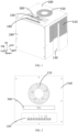
- the water receiving tray is below the evaporator, the condenser and the axial flow fan, and divides the housing into an axial flow duct for heat exchange, and an installation cavity for installing other common components of the dehumidifier (such as an electric control box, a fan capacitor, etc.).
- the space is fully and reasonably used, and the rationality of the air duct is ensured (to avoid the excessive dispersion of the air flow in the housing, which leads to a low flow rate and affects the dehumidification efficiency), and the compactness of the arrangement of the components is improved, the space utilization rate is improved, and the volume of the body is reduced, thereby facilitating the transportation and storage of the body.
- the arrangement of the body does not need to consider the arrangement of the water tank, the arrangement of components inside the body is more reasonable and compact.
- the directional indication is only used to explain the relative positional relationship, movement, etc. of the components in a certain posture (as shown in the drawings). If the specific posture changes, the directional indication will change accordingly.
- the present invention provides a dehumidifier, which mainly provides an arrangement relationship between a body 100 and a water tank 200.
- the body 100 has a dehumidification function.
- the dehumidifier When the dehumidifier is in a working state, the water tank 200 is to store water formed by the body 100, and when the dehumidifier is in an idle state, the water tank 200 is to house the body 100.
- a volume of the water tank 200 is greatly increased, so that the water tank 200 can store more water, a continuous working time of the dehumidifier is greatly extended, the number of times the user pours water is reduced, and the user experience is improved.
- the volume of the dehumidifier can be greatly reduced, and the amount of containers during transportation can be increased, which is beneficial to greatly reducing transportation and storage costs. Based on this, corresponding improvements have been made to the air duct structure of the body 100, supporting method, form of the water tank 200, a water level switch 600, form of a handle 300', winding structure, etc..
- the following will mainly use examples to describe the specific structure of the dehumidifier. Specifically, first introduce the overall and supporting relationship of the body 100 and the water tank 200, then respectively introduce the form of the water tank 200, the winding structure and the water level switch 600, and then introduce the air duct system and the form of the handle 300'.
- the dehumidifier comprises:
- the dehumidifier has a working state and an idle state.
- the receiving cavity 210 of the water tank 200 is configured to accommodate the water formed by the dehumidification of the body 100, and in the idle state, the receiving cavity 210 is configured to accommodate at least a part of the body 100.
- the body 100 has a dehumidification function, that is, the body 100 can remove moisture in the air.
- dehumidification There are many ways to dehumidify, such as condensation dehumidification, compression dehumidification and adsorption dehumidification.
- Condensation dehumidification that is, the atmospheric air is cooled to below the dew point temperature to condense water vapor into condensed water.
- Compression dehumidification that is, air is compressed and then cooled to condense water vapor in the air into water.
- Adsorption dehumidification can be dehumidified by solid adsorption or liquid adsorption.
- a refrigerant circulation system formed by a combination of a compressor 550, an evaporator 510, a condenser 520, a throttling device, etc., to cool and dehumidify air is taken as an example.
- a compressor 550 an evaporator 510, a condenser 520, a throttling device, etc.
- the overall shape of the receiving cavity 210 of the water tank 200 is similar to the overall shape of the body 100, so that the body 100 can be installed while saving space.
- the body 100 can be directly above the water tank 200, so that the generated condensate can flow into the water tank 200 under the action of gravity.
- the stability of the dehumidifier in the working state gradually increases.
- the water tank 200 can also be directly above the body 100 in the working state, or, the water tank 200 is alongside the body 100.
- a water pump needs to be provided to pump the water in the water tank 200 to the upper water tank 200.
- the entire water tank 200 can hold water, so that the volume of the water tank 200 can be greatly increased, which is beneficial to reduce the number of times of pouring water by the user. It is worth noting that alongside refers to roughly parallel, allowing small deviations.
- the dehumidifier When the dehumidifier is in the idle state, part of the body 100 or the whole body 100 is housed in the receiving cavity 210 of the water tank 200.
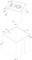
- the body 100 There are many ways for housing the body 100. If the water tank 200 is placed with the opening facing upward, the body 100 is placed in and out of the receiving cavity 210 through the opening in the up and down directions. The specific form is that the opening of the water tank 200 faces upward, and the body 100 enters and exits the water tank 200 through the opening.
- the body 100 can also be placed on the ground, the water tank 200 can be turned upside down, and to cover the body 100. Either way, the volume of the dehumidifier in the idle state is greatly reduced, so that the amount of containers can be increased during storage and transportation, which is conducive to substantial savings in transportation and storage costs.
- the overall shape and size of the body 100 are equivalent to the shape and size of the receiving cavity 210.
- the height of the body 100 is equivalent to the height of the receiving cavity 210.
- the overall shape of the body 100 is a cylindrical shape, and the overall shape of the receiving cavity 210 is also a cylindrical space.
- the body 100 comprises a housing 190.
- the housing 190 has an air inlet 110, an air outlet 120, and an air duct communicating with the air inlet 110 and the air outlet 120.
- An air duct assembly and a heat exchanger assembly are provided in the air duct.
- the air inlet 110 and the air outlet 120 can be set.
- the air inlet 110 may be defined at the peripheral side (front, rear, left, right) or top of the housing 190.
- the air outlet 120 may be defined at the peripheral side (front, rear, left, right) or top of the housing 190. Take the air inlet 110 defined at the peripheral side wall of the housing 190 and the air outlet 120 at the top of the housing 190 as an example.
- a filter screen may be provided at the positions of the air inlet 110 and the air outlet 120.
- a number of mesh holes may be directly formed on the housing 190 to replace the filter screen.
- the dehumidifier is divided into the body 100 and the water tank 200.
- the body 100 has an independent dehumidification function, which can collect water vapor in the air.
- the body 100 is above the entire water tank 200, so that the entire water tank 200 can hold water.
- the volume and utilization rate of the water tank 200 can be greatly increased, so that the continuous working time of the dehumidifier can be greatly extended, the number of times the user pours water is reduced, and the user experience is improved.
- the body 100 is at least partially contained in the receiving cavity 210, which greatly reduces the volume of the dehumidifier in the idle state, and can increase the amount of containers during storage and transportation, which greatly saves transportation and storage costs.
- the top of the water tank 200 is provided with a supporting structure, and the body 100 is provided on the supporting structure.
- the supporting structure may be a structure that is fixedly connected to the water tank 200, or may be a structure that is movably connected to water tank 200. If the supporting structure is fixedly connected to the water tank 200, in order to improve the utilization of space as much as possible, it is necessary to provide an avoidance position corresponding to the supporting structure on the outer side wall of the body 100, so that the body 100 can be smoothly placed in the water tank 200 after adjusting a certain angle.
- the supporting structure is movably connected to the water tank 200, when the dehumidifier is in the working state, the supporting structure extends into the receiving cavity 210 to support the body 100.
- the supporting structure exits the receiving cavity 210 so that the body 100 can be received in the water tank 200 smoothly.
- the supporting structure is movably provided on the water tank 200, so that the supporting structure extends into the receiving cavity 210 when the dehumidifier is in the working state, and exits the receiving cavity 210 when the dehumidifier is in the idle state.
- the supporting structure in order to further improve the installation stability of the body 100 in the working state, is provided on the inner side wall of the receiving cavity 210, and the top of the supporting structure is lower than the edge of the opening of the water tank 200. In this way, when the body 100 is supported by the supporting structure, a part of the body 100 is located in the water tank 200, such that the center of gravity moves downward, the body 100 is more limited by the inner side wall of the water tank 200, and the stability of the dehumidifier is further improved.
- the supporting structure is provided on the water tank 200.
- the supporting structure is fixedly provided on the water tank 200.
- the water tank 200 has a receiving cavity 210, and the inner side wall of the receiving cavity 210 has a supporting boss 220.
- the dehumidifier has a working state, and in the working state, the bottom of the body 100 abuts on the supporting boss 220.
- the supporting boss 220 can have many shapes, such as a square, an arc, a circle, etc.. Take the shape of the supporting boss 220 similar to the shape of the inner wall of the receiving cavity 210 as an example.
- the cross section of the supporting boss 220 may be rectangular, and when the inner side wall of the receiving cavity 210 is a curved surface, the cross section of the supporting boss 220 may be curved. In this way, the utilization rate of the supporting boss 220 can be improved as much as possible, and the contact region between the bottom of the body 100 and the supporting boss 220 can be increased.
- the supporting surface of the supporting boss 220 being a plane is taken as an example.
- the dehumidifier is divided into the body 100 and the water tank 200.
- the body 100 has an independent dehumidification function, which can collect water vapor in the air, and the supporting boss 220 is provided on the inner side wall of the water tank 200.
- the bottom of the body 100 can abut on the supporting boss 220, so that the body 100 is matched with the water tank 200, and the body 100 is above the entire water tank 200, so that the entire water tank 200 can hold water.
- the volume and utilization rate of the water tank 200 can be greatly increased, the continuous working time of the dehumidifier can be greatly extended, the number of times the user pours water is reduced, and the user experience is improved.
- the outer side wall of the body 100 has an avoidance groove 130 corresponding to the supporting boss 220.
- the dehumidifier has an idle state. When the dehumidifier is in the idle state, the supporting boss 220 is received in the avoidance groove 130, so that the body 100 is at least partially received in the receiving cavity 210. When the dehumidifier is in the working state, the avoidance groove 130 is staggered and placed on the supporting boss 220. The avoidance groove 130 is provided on the outer side wall of the body 100. When the avoidance groove 130 corresponds to the supporting boss 220, the body 100 can be received in the receiving cavity 210.
- the bottom of the body 100 is supported by the supporting boss 220.
- misalignment There are many ways of misalignment, which are related to the specific shapes of the body 100 and the water tank 200.
- the two supporting bosses 220 can be arranged in a symmetrical structure (two supporting bosses 220 are provided on two opposite or adjacent side walls). After the body 100 is adjusted by 180°, the misalignment of the avoidance groove 130 and the supporting boss 220 can be realized.
- the misalignment of the avoidance groove 130 and the supporting boss 220 can be realized.
- the cross-sections of the water tank 200 and the body 100 are both circular-like, there are many rotation angles that can be misaligned, and it is only necessary that the avoidance groove 130 does not correspond to the supporting boss 220.
- the supporting boss 220 is vertical along the height direction of the water tank 200, and the avoidance groove 130 is vertical along the height direction of the outer side wall of the body 100.
- the supporting boss 220 and the avoidance groove 130 are vertical, so that when the body 100 enters the water tank 200, it can be straight up and down, which is beneficial to the convenient movement of the body 100.
- the avoidance groove 130 also plays a guiding role during the movement of the body 100, and the supporting boss 220 plays the role of a guide post, such that the body 100 can accurately fall into a preset position in the water tank 200 along the supporting boss 220.
- the outer side wall of the water tank 200 is provided with a groove corresponding to the supporting boss 220.
- the groove can be used as a clasp groove 230 of the water tank 200 to facilitate the transportation of the water tank 200.
- the clasp groove 230 can have many forms, such as through a later process, or directly integral injection molding.
- the groove is formed by protruding from the side wall of the water tank 200 into the water tank 200, and the protruding portion forms the supporting boss 220. In this way, while simplifying the process, the materials used are reduced, and the material cost and the process cost are saved.
- the number of the supporting bosses 220 is two, which are provided on two opposite side walls of the water tank 200.
- the number of the avoidance grooves 130 is two, which are provided on two opposite side walls of the body 100.
- the supporting bosses 220 are provided on the two opposite side walls of the water tank 200, such that the opposite sides of the body 100 are supported, which is beneficial to improve the stability of the body 100.
- the top of the supporting boss 220 is lower than the edge of the opening of the water tank 200. In this way, the bottom of the body 100 is partially located in the receiving cavity 210, so that the body 100 is more restricted by the side wall of the receiving cavity 210. In addition, it is also conducive to lowering the overall center of gravity of the dehumidifier, which is conducive to improving the overall stability of the dehumidifier.
- the supporting structure is provided on the water tank 200.
- the supporting structure is movably connected to the water tank 200.
- the dehumidifier comprises a supporting member 250 movably connected to the water tank 200.
- the dehumidifier has a working state and an idle state. When the dehumidifier is in the working state, the supporting member 250 extends into the receiving cavity 210 to support the body 100. When the dehumidifier is in the idle state, the supporting member 250 exits the receiving cavity 210 so that the body 100 can be at least partially received in the receiving cavity 210.
- the supporting member 250 can have many forms, such as a rod shape, a block shape, and so on.
- the supporting member 250 can be movably connected to the water tank 200, such as moving relative to the water tank 200, rotating relative to the water tank 200, and so on. That is to say, the supporting member 250 realizes the two actions of extending into the receiving cavity 210 and exiting the receiving cavity 210 by rotating or moving.
- the position of the rotation may be on the side wall of the water tank 200.
- the dehumidifier is divided into the body 100 and the water tank 200.
- the body 100 has an independent dehumidification function, which can collect water vapor in the air, and the supporting member 250 is provided on the side wall of the water tank 200.
- the supporting member 250 extends into the receiving cavity 210, and the bottom of the body 100 can abut on the supporting member 250, so as to realize the cooperation of the body 100 with respect to the water tank 200, and the body 100 is above the entire water tank 200, so that the entire water tank 200 can hold water.
- the volume and utilization rate of the water tank 200 can be greatly increased, the continuous working time of the dehumidifier can be greatly extended, the number of times the user pours water is reduced, and the user experience is improved.
- the supporting member 250 exits the receiving cavity 210, so that the body 100 can be at least partially received in the water tank 200, which greatly reduces the volume of the dehumidifier after assembly. In this way, the amount of containers can be increased during storage and transportation, and the cost of transportation and storage can be greatly saved.
- the inner side wall of the receiving cavity 210 has a drawing opening, and the supporting member 250 can be pushed and pulled into the drawing opening. With the drawing opening, the supporting member 250 can enter and exit the receiving cavity 210 through the drawing opening. When it is necessary to support the body 100, the supporting member 250 can be pushed into the receiving cavity 210. When the body 100 needs to be located into the water tank 200, the supporting member 250 can be drawn out from the receiving cavity 210, which is simple to operate.
- the supporting member 250 comprises a supporting portion 251, a holding portion 253, and a connecting arm 252 connecting the supporting portion 251 and the holding portion 253.
- the holding portion 253 is located outside the water tank 200.
- the supporting portion 251 is located in the receiving cavity 210 in a working state, and exits the receiving cavity 210 in an idle state.
- the supporting portion 251 is to support the body 100, and the holding portion 253 is for the operator to hold.
- the supporting portion 251 is connected to the holding portion 253 through the connecting arm 252, and the holding portion 253 can control the position of the supporting portion 251 through the connecting arm 252.
- the operator can use the supporting portion 250 as a handle 300 to carry the water tank 200 or the dehumidifier in an idle state. In this way, the utilization rate of the supporting portion 250 is improved.
- the length of the supporting portion 251 is greater than the width of the connecting arm 252, the drawing opening is a stepped opening, and an end with a larger size is close to the receiving cavity 210 and can receive the supporting portion 251. That is, the length of the larger end of the drawing opening is greater than or equal to the length of the supporting portion 251.
- the supporting portion 251 exits the receiving cavity 210, it is contained in the drawing opening so that the supporting portion 251 does not protrude from the inner side wall of the receiving cavity 210. In this way, the supporting portion 251 does not interfere with the movement of the body 100 in the water tank 200 at all.
- the length of the supporting portion 251 is greater than the length of the smaller end of the drawing opening. In this way, the supporting portion 251 cannot be separated from the water tank 200 through the drawing opening. That is, no matter in the working state or in the idle state, the supporting member 250 is always connected to the water tank 200, so that the supporting member 250 is prevented from being lost.
- the width of the holding portion 253 is greater than the width of the smaller end of the drawing opening, and/or, the length of the holding portion 253 is greater than the length of the smaller end of the drawing opening. In this way, through the limitation of the size, the holding portion 253 cannot enter the drawing opening, so that the operator can easily grasp the holding portion 253 at any time, which is convenient for the operation of the operator.
- the side of the holding portion 253 away from the outer side wall of the water tank 200 has a handshake arc surface.
- the operator grasps the holding portion 253 through the arc of the handshake, the operator will not be scratched by the edges and corners.
- the contact region between the holding portion 253 and the hand is also increased, which is beneficial for the operator to hold the holding portion 253 more stably and reliably.
- the dehumidifier further comprises a reinforcing plate 260, the reinforcing plate 260 is provided at a position corresponding to the drawing opening, and the drawing opening penetrates the reinforcing plate 260 and the side wall of the water tank 200.
- the reinforcing plate 260 Through the arrangement of the reinforcing plate 260, the carrying capacity around the drawing opening is increased, thereby increasing the carrying capacity of the water tank 200, which is beneficial to improving the reliability of the dehumidifier.
- the supporting member 250 is provided on the upper of the water tank 200. In this way, both the middle and the lower portion of the water tank 200 can hold water, which helps to ensure an effective water holding space of the water tank 200.
- the number of the supporting members 250 is two, which are provided on two opposite side walls of the water tank 200.
- the body 100 has a dehumidification function.
- the overall shape of the body 100 is cylindrical-like.
- the water tank 200 has a receiving cavity 210, and the water tank 200 has a cylindrical shape.
- the dehumidifier has an idle state, and in the idle state, the body 100 is at least partially contained in the water tank 200.
- the overall shape of the body 100 is cylindrical-like, which means that the overall shape is cylindrical-like, and due to the requirements of process and installation, protrusions or recesses are formed on the outer surface of the cylinder.
- the water tank 200 has a cylindrical shape, which means that the overall shape of the water tank 200 is a cylindrical shape. According to requirements such as process and installation coordination, protrusions or recesses are formed on the surface or inner side wall of the water tank 200.
- the overall shape of the body 100 is cylindrical-like, and the water tank 200 is cylindrical-like, so that when the body 100 is placed into the water tank 200, compared with shapes with sharp corners, there is no strict directivity, which facilitates the placement of the body 100 in the water tank 200, and is beneficial to improve the efficiency of putting the body 100 in the water tank 200.
- the inner side wall of the receiving cavity 210 has a supporting boss 220.
- the dehumidifier has a working state, and in the working state, the bottom of the body 100 abuts on the supporting boss 220.
- the outer side wall of the body 100 has an avoidance groove 130 corresponding to the supporting boss 220.
- the dehumidifier has an idle state, and in the idle state, the supporting boss 220 is received in the avoidance groove 130, so that the body 100 is at least partially received in the receiving cavity 210. In the working state, the avoidance groove 130 is misaligned with the supporting boss 220.
- the supporting boss 220 in order to improve the utilization rate of the supporting boss 220, is in an arc shape along the inner side wall of the receiving cavity 210 in its width direction. In this way, the bottom of the body 100 can abut as many supporting bosses 220 as possible.
- the number of the supporting bosses 220 is at least two, the at least two supporting bosses 220 are spaced apart from each other along the circumferential direction of the inner side wall of the receiving cavity 210, and the number of the avoidance grooves 130 is two, and the corresponding supporting bosses 220 are spaced apart from each other on the outer side wall of the body 100.
- a drainage hole 240 is provided at the lower or bottom of the water tank 200. Through the arrangement of the drainage hole 240, the water in the water tank 200 can be drained through the drainage hole 240, without requiring the user to lift the water tank 200 to pour water, which is beneficial to the user's use.
- the dehumidifier comprises a protective member, and the protective member is provided on the upper of the inner side wall of the water tank 200, and/or, is provided on the lower of the outer side wall of the body 100.
- the dehumidifier has an idle state. When the dehumidifier is in the idle state, the body 100 can be at least partially received in the water tank 200 through an opening.
- the protective member such as a sheet, a strip, or a block.
- the protective member can also be made of many kinds of materials, such as elastic materials, such as rubber, elastic plastic, etc., or flexible materials, such as cotton wool fabrics.
- the protective member is mainly to isolate the outer side wall of the body 100 and the inner side wall of the water tank 200 to prevent the outer side wall of the body 100 from being scratched. Therefore, the protective member can be provided on the outer side wall of the body 100 or on the inner side wall of the receiving cavity 210.
- the protective member is provided between the outer side wall of the body 100 and the inner side wall of the water tank 200. Therefore, the outer side wall of the body 100 is prevented from directly contacting and rubbing with the inner side wall of the water tank 200, which can protect the outer side wall of the body 100 and avoid the outer side wall of the body 100 from being scratched.
- the top of the protective member is flush with the top of the opening side of the water tank 200; or, the bottom of the protective member is flush with the bottom of the body 100.
- the protective member is provided at the opening of the water tank 200 or the bottom of the body 100, such that when the body 100 first contacts with the water tank 200, the protective member can play a role of isolation, until the body 100 completely enters the water tank 200. In this way, the utilization rate of the protective member is improved.
- the protective member connects to the inner side wall of the water tank 200 or the outer side wall of the body 100.
- the protective member is adhered to the inner side wall of the water tank 200 or the outer side wall of the body 100.
- the inner side wall of the water tank 200 or the outer side wall of the body 100 is provided with a snap slot, and the protective member is snapped in the snap slot.
- the outer side of the protective member protrudes from the outer side wall of the body 100 or the inner side wall of the water tank 200.
- the protective member including a protective strip is taken as an example.
- the protective strip extends along the circumference of the water tank 200 or extends along the circumference of the body 100. That is, the protective member is around the inner side wall of the water tank 200 or around the outer side wall of the body 100.
- the protective strip can be a continuous long strip or a short intermittent strip. In this way, the periphery of the body 100 will not be scratched due to the cooperation with the water tank 200, which is beneficial to maintaining the appearance of the outer side wall of the body 100.
- FIG. 17 a winding structure is shown.
- the outer side of the body 100 has a storage groove 160 recessed into the inside of the body 100 for receiving the power cord of the dehumidifier.
- the storage groove 160 can have many shapes, such as a cuboid, a cylinder, and the like, and the shape of the storage groove 160 can be adapted to the overall shape of the body 100.
- the side surface forming the storage groove 160 is a flat surface
- the storage groove 160 may be cuboid.
- the side surface forming the storage groove 160 is a cylindrical surface
- the storage groove 160 may be cylindrical. With the arrangement of the storage groove 160, the power cord can be completely received in the storage groove 160.
- the outer side of the body 100 has a storage groove 160 recessed into the inside of the body 100 for receiving the power cord of the dehumidifier.
- the power cord of the dehumidifier is stored in the storage groove 160 so that the power cord does not protrude from the peripheral side of the body 100, and the body 100 can be conveniently and quickly placed into the water tank 200.
- the dehumidifier in order to further ensure that the power cord can be stably stored in the storage groove 160, also comprises a strap.
- the strap locks the power cord and is stored in the storage groove 160.
- straps Take a flexible ribbon as an example, such as rubber bands, cable ties, and so on.
- structural components can be provided in the storage groove 160.
- the dehumidifier further comprises a disk storage column 171 and a limiting stopper 172.
- One end of the disk storage column 171 is fixedly connected to the side wall of the storage groove 160, the other end is fixedly connected to the limiting stopper 172, and the limiting stopper 172 does not protrude from the notch of the storage groove 160.
- the power cord can be wound around the storage column 171.
- the power cord coiled on the disk storage column 171 is stopped by the limiting stopper 172 and will not break away from and exceed the limiting stopper 172, that is, it will not protrude from the outer surface of the body 100. In this way, the storage of the power cord in the idle state can be effectively guaranteed.
- the groove wall to which the disk storage column 171 is connected is opposite to the notch. In this way, the operator can watch to the coiled position, and the operable space is very large, which is convenient for the user's operation.
- a wiring groove 181 is also formed on the surface of the body 100 near the storage groove 160 to limit the direction of the power cord.
- the power cord may be provided in the wiring groove 181, a depth of the wiring groove 181 is greater than a diameter of the power cord, so that the power cord can be received in the wiring groove 181.
- the wiring groove 181 is in communication with the storage groove 160. In this way, the power cord can directly enter the wiring groove 181 from the storage groove 160 without protruding from the outer surface of the body 100 in the middle.
- the outer side wall of the body 100 is provided with a rib 182.
- the rib 182 and the wiring groove 181 enclose to form a limit wire groove that defines the position of the power cord.
- the rib 182 is disposed on the side wall of the wiring groove 181, and the outer surface of the rib 182 is flush with the outer side wall of the body 100. In this way, when the power cord is in the wiring groove 181, it will not leave the wiring groove 181 under the action of gravity or a slight external force, so that the wiring of the power cord is very reliable, which is beneficial to improve the stability of the dehumidifier.
- the wall of the storage groove 160 is also provided with a receiving hole 173 for installing the power plug.
- the receiving hole 173 can have a variety of forms. Through the arrangement, it is possible to store plugs of different models and different countries.
- detecting water level There are many ways for detecting water level, which can be wireless detection (such as ultrasonic detection, capacitance detection) or physical detection (floating ball detection). The following specific examples are used for description.
- the dehumidifier comprises an ultrasonic water level detection device configured to detect the water level in the water tank 200, the ultrasonic water level detection device is electrically connected to an electric control main board of the dehumidifier, and a main control circuit is provided on the electric control main board.
- the ultrasonic water level detection device sends the detected water level information in the water tank 200 to the electronic control main board.
- the electric control main board determines the current water level, and ignores the detection result when the current water level does not reach the preset water level. When the current water level reaches the preset water level, the dehumidification is stopped to prevent the water from increasing and overflowing the water tank 200, causing immeasurable consequences.
- the dehumidifier also comprises an alarm device electrically connected to the electronic control main board and/or the ultrasonic water level detection device.
- the electronic control main board controls the alarm device to alert the user to remind the user that the current water level situation requires the user to deal with it in time.
- the alarm device is directly electrically connected to the ultrasonic water level detection device. In this way, the alarm device can directly send an alarm based on the detection result of the water level detection device.
- the body 100 is located directly above the water tank 200, and the ultrasonic water level detection device is provided at the bottom of the body 100.
- the dehumidifier further comprises a display device 140, and the ultrasonic water level detection device is electrically connected to the display device 140.
- the display device 140 is beneficial for the user to intuitively monitor the working condition of the dehumidifier, and the current water level in the water tank 200 can also be observed from the display device 140. There are many positions where the display device 140 can be set. Taking the display device 140 on the top of the body 100 as an example. In some embodiments, the display device 140 may also be provided on the front side of the body 100.
- the dehumidifier comprises a water level switch 600
- the water level switch 600 is provided at the bottom of the body 100
- the water level switch 600 comprises a float 610.
- the dehumidifier has an idle state, and when the dehumidifier is in the idle state, the receiving cavity 210 accommodates at least a part of the body 100.
- the bottom of the body 100 has a receiving groove 640 recessed into the body 100, and the float 610 is movably connected to the body 100, the float 610 can be completely received in the receiving groove 640 when the dehumidifier is in the idle state.
- the water level switch 600 is configured to detect the water level in the water tank 200, and the water level switch 600 comprises a float 610.
- the float 610 When the water level switch 600 detects the water level, the float 610 is in contact with the liquid surface, or is suspended. When the liquid level reaches a certain position and contacts the float 610, the float 610 is supported. As the liquid level rises, the position of the float 610 changes, and the water level is determined according to the height change of the float 610. What changes with the position of the float 610 can be a capacitance or a magnetic induction intensity. According to the change of the capacitance or the change of the magnetic induction intensity, the working condition of the dehumidifier is controlled.
- a receiving groove 640 that can completely receive the float 610 is defined at the bottom of the body 100.
- the float 610 can be completely received in the receiving groove 640.
- the water level switch 600 is provided at the bottom of the body 100, and a receiving groove 640 recessed into the body 100 is provided at the bottom of the body 100, such that the float 610 can be completely received in the receiving groove 640 when the dehumidifier is in the idle state, so that the float 610 can be arranged without protruding from the body 100.
- a receiving groove 640 recessed into the body 100 is provided at the bottom of the body 100, such that the float 610 can be completely received in the receiving groove 640 when the dehumidifier is in the idle state, so that the float 610 can be arranged without protruding from the body 100.
- the water switch further comprises a guide rod 620 connected to the float 610
- the body 100 has a guide hole 630 communicating with the receiving groove 640, and one end of the guide rod 620 away from the float 610 is movably mounted in the guide hole 630.
- the guide rod 620 moves along the guide hole 630, with the force of the float 610 on the guide rod 620, the guide rod 620 moves along the guide hole 630 towards the inside of the body 100.
- the float 610 is completely squeezed into the receiving groove 640.
- the guide hole 630 is vertically provided directly above the receiving groove 640. In this way, the guide rod 620 and the float 610 are straight up and down along the guide hole 630, the moving direction of the float 610 and the guide rod 620 is consistent with the force direction of the float 610 (the gravity and the buoyancy of water on the float 610), which facilitates the up and down movement of the float 610.
- the water level switch 600 is a magnetic control switch, and the detection state of the water level switch 600 comprises a turn off state and a turn on state. In the detection state, the float 610 extends out of the receiving groove 640 to protrude from the bottom of the body 100.
- the water level switch 600 comprises a magnetic float switch.
- a magnetic member may be provided in the float ball to change the magnetic field as the float 610 moves. As the float 610 rises, the intensity of the magnetic field at the bottom of the body 100 increases.
- the water level switch 600 is a magnetic control switch, which is beneficial for the water level switch 600 to quickly and accurately detect the current water level.
- the water level switch 600 is electrically connected to the electronic control main board of the dehumidifier, the dehumidifier further comprises an alarm device, and the alarm device is electrically connected to the electronic control main board and/or the water level switch 600.
- FIG. 20 to FIG. 25 an axial flow duct system is shown.
- the dehumidifier comprises: a body 100, the body 100 comprises a housing 190, the housing 190 has an air inlet 110, an air outlet 120, and an air duct communicating with the air inlet 110 and the air outlet 120.
- An axial flow fan is provided in the air duct, and the air direction of the axial flow fan is towards the air outlet 120.
- a compressor 550 is provided in the housing 190 and is alongside the axial flow fan.
- the axial flow fan is alongside the compressor 550.
- the axial flow fan and the compressor can extend, such as both vertical or both horizontal. Taking the two both vertical as an example, the two at least partially overlap in the vertical direction.
- the top of the compressor 550 extends to the middle or upper of the drive motor 530.
- the arrangement of the compressor 550 and the axial flow fan greatly reduces the height of the entire body 100.
- the axial flow fan is alongside the compressor 550.
- the space occupied by the axial flow fan and compressor 550 in the height direction is greatly reduced, thereby improving the compactness of the internal component arrangement of the dehumidifier, so that the height of the body 100 can be greatly reduced, which is conducive to reducing the height and volume of the body 100, thereby facilitating the transportation and storage of the body 100.
- the arrangement of the body 100 does not need to consider the arrangement of the water tank 200, the original arrangement inside the body 100 is more reasonable and compact.
- the dehumidifier comprises an evaporator 510 and a condenser 520 that are stacked on top of each other.
- the evaporator 510 and/or the condenser 520 are U-shaped in the air duct, and the axial flow fan is located in the region surrounded by the evaporator 510 and the condenser 520.
- the evaporator 510 and/or the condenser 520 are U-shaped, so that the axial flow fan can be provided in the U-shaped region.
- the space is fully utilized and the compactness of the structure is improved, and each portion of the evaporator 510 and the condenser 520 can obtain a considerable negative pressure (the axial flow fan transports the air in the U-shaped region out of the air duct, forming a negative pressure in the U-shaped region), such that the air flow passing through each portion of the evaporator 510 and the condenser 520 is equal, which is beneficial to greatly improve the efficiency of the evaporator 510 and the heat exchanger.
- the evaporator 510 and/or the condenser 520 are U-shaped, the heat exchangers of the evaporator 510 and the condenser 520 are greatly increased, which is beneficial to improve the dehumidification efficiency of the dehumidifier.
- the air inlet 110 is defined corresponding to multiple surfaces of the U-shaped evaporator 510 and the condenser 520. Taking the air inlets 110 on the left, right, and rear sides as an example, they correspond to the U-shaped arms on both sides and the middle portion respectively. In this way, sufficient air flow is provided for the heat exchange between the evaporator 510 and the condenser 520.
- the evaporator 510 in order to improve the dehumidification effect, is disposed close to the inner side wall of the housing 190, and the condenser 520 is disposed close to the axial flow fan.
- the air first passes through the evaporator 510 to cool down and dehumidify, and then passes through the condenser 520 to heat it back to temperature, which is beneficial to improve the dehumidification effect.
- the air inlet 110 is provided on the top of the body 100.
- the bottom of the compressor 550 is fixedly connected to the bottom of the housing190 and is vertical.
- the axial flow fan comprises a drive motor 530 and an axial flow impeller 540.
- the drive motor 530 is vertically provided corresponding to the air outlet 120.
- the axial flow impeller 540 is close to the air outlet 120.
- the dehumidifier comprises a body 100, and the body 100 comprises:
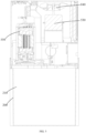
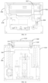
- the water receiving tray 750 is below the condenser 520, the evaporator 510 and the axial flow fan, and configured to divide the housing 190 into an axial flow duct and an installation cavity for mounting other components.
- the water receiving tray 750 is in the shape of a flat plate and not only has parts corresponding to the condenser 520 and the evaporator 510, but also has parts corresponding to the axial flow fan. Therefore, the air flow in the axial flow duct can directly flow out from the air outlet 120 without chaosing in the air duct.
- the evaporator 510, the condenser 520 and the axial flow fan are all provided vertically as an example.
- the axial flow fan provides power for driving airflow
- the axial flow fan is parallel to the evaporator 510 and the condenser 520 in the vertical direction.
- the compact setting of the three is conducive to using space fully and reasonably.
- the water receiving tray 750 is below the evaporator 510, the condenser 520 and the axial flow fan, and divides the housing 190 into an axial flow duct for heat exchange, and an installation cavity for installing other common components of the dehumidifier (such as an electric control box 710, a fan capacitor 720, etc.).
- the space is fully and reasonably used, and the rationality of the air duct is ensured (to avoid the excessive dispersion of the air flow in the housing 190, which leads to a low flow rate and affects the dehumidification efficiency), and the compactness of the arrangement of the components is improved, the space utilization rate is improved, and the volume of the body 100 is reduced, thereby facilitating the transportation and storage of the body 100.
- the arrangement of the body 100 does not need to consider the arrangement of the water tank 200, the arrangement of components inside the body 100 is more reasonable and compact.
- the compressor 550 of the dehumidifier is vertically provided at the bottom of the housing 190, and the water receiving tray 750 is provided with an avoidance notch corresponding to the compressor 550.
- the compressor 550 is alongside the axial flow fan, and the top of the compressor 550 extends to the middle or even the upper portion of the axial flow fan.
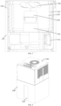
- the dehumidifier further comprises an isolation plate 730 located in the installation cavity.
- One side of the isolation plate 730 is connected to a bottom of the housing 190, and the opposite side of the isolation plate 730 is fixedly connected to a bottom of the water receiving tray 750.
- the isolation plate 730 supports the water receiving tray 750.
- the isolation plate 730 can support the water receiving tray 750 to prevent the evaporator 510, the condenser 520, and the axial flow fan from being damaged by a large collision.
- the isolation plate 730 also provides a location for the installation of components, so that multiple components of the dehumidifier can be conveniently installed on the isolation plate 730.
- an electric control box 710 is provided on the isolation plate 730, and/or a fan capacitor 720 is provided on the isolation plate 730, and/or a water level switch 600 is provided in the installation cavity. That is, an electric control box 710 and a fan capacitor 720 may be provided on the isolation plate 730, and the water level switch 600 may also be provided on the isolation plate 730. In this way, while providing support for the components in the axial flow duct, it also provides space for the installation of components. In order to use the space more reasonably, the fan capacitor 720, the electric control box 710, etc., can be installed on different isolation plates 730.
- the isolation plate 730 comprises at least two sub-baffles, and the two sub-baffles are arranged in the installation cavity at an angle.
- the dehumidifier comprises a compressor capacitor 740 and an electric control box 710, and the compressor capacitor 740 and the electric control box 710 are installed on different sub-baffles.
- the electric control box 710 can be installed on the sub-baffle on the right side
- the compressor capacitor 740 can be installed on the sub-baffle on the rear side.
- the larger components are provided separately, so that the components can be installed without mutual influence between the components, which is beneficial to improve the compactness and stability of the structure.
- the dehumidifier further comprises an arc-shaped fastening member, an installation notch 731 is defined on the sub-baffle where the compressor capacitor 740 is installed, the compressor capacitor 740 is snapped in the installation notch 731, and is fixed on the sub-baffle through the arc-shaped fastening member.
- both the evaporator 510 and the condenser 520 are U-shaped in the housing 190, and the axial flow fan is located in a region surrounded by the evaporator 510 and the condenser 520.
- the air outlet 120 is located at a top of the housing 190, a bottom of the compressor 550 is fixedly connected to a bottom of the housing 190 and is vertical, the axial flow fan comprises a drive motor 530 and an axial flow impeller 540, the drive motor 530 is vertical corresponding to the air outlet 120, and the axial flow impeller 540 is close to the air outlet 120.
- a drainage hole 165 is provided on the rear side of the housing 190.
- One end of the drainage hole 165 is in communication with the water receiving tray 750, and the other end of the drainage hole 165 is in communication with the outside.
- the body 100 has a sink hole 166 along the height direction of the body 100.
- One end of the sink hole 166 is in communication with the water receiving tray 750, and the other end of the sink hole 166 is in communication with the below of the body 100. That is to say, the dehumidifier has two sets of drainage systems. When the dehumidifier can be connected to an external drainage pipe, the condensed water can be directly discharged through the external drainage pipe.
- the condensed water can be stored in the water tank 200 under the body 100 through the sink hole 166.
- the dehumidifier can be adapted to different working environments, which is beneficial to improve the adaptability of the dehumidifier.
- a handle 300' is shown.
- the dehumidifier comprises a handle 300', and a drawing opening is provided on the top of the body 100.
- the handle 300' is movably installed on the drawing opening, so that the handle 300' will not protrude from the peripheral side of the body 100 when it is working or idle.
- the dehumidifier is divided into the body 100 and the water tank 200, and the body 100 has the independent dehumidification function, which can collect water vapor in the air.
- the body 100 is at least partially received in the receiving cavity 210, which greatly reduces the volume of the dehumidifier when the dehumidifier is idle, increases the amount of cabinets during storage and transportation, and greatly saves transportation and storage costs.
- a drawing opening is provided on the top of the body 100, and the handle 300' is movably connected to the drawing opening, such that the handle 300' will not protrude from the peripheral side of the body 100 when it is working or idle. In this way, the body 100 can be conveniently and quickly placed into the water tank 200.
- the body 100 has a receiving space, and the handle 300' can be stored in the receiving space when the handle 300' is not in use.
- the receiving space allows the handle 300' to be accommodated in the space without protruding from the top of the body 100.
- the handle 300' will not cover the view of the top of the body 100, will not affect the viewing of the display device 140, and will not affect the air out from the air outlet 120.
- the handle 300' comprises a horizontal grip rod 310' and a vertical guide 320'.
- One end of the guide rod 320' is connected to the grip rod 310'.
- the guide rod 320' is provided with a guide groove 321' whose two ends are closed.
- the body 100 is provided with a fixing post 330' corresponding to the drawing opening.
- the guide groove 321' is sleeved on the fixing post 330'.
- the fixing post 330' is fixedly connected to the body 100.
- the handle 300' When the handle 300' is lifted upward, the lower end of the guide groove 321' abuts against the fixing post 330', and the weight of the body 100 is transmitted to the handle 300' through the fixing post 330'.
- the handle 300' When the handle 300' is placed downward, the upper end of the guide groove 321' abuts against the fixing post 330' to support the handle 300'.
- the number of the guide rod 320' is two.
- the two guide rods 320' are respectively arranged at the two ends of the grip rod 310'. In this way, the body 100 can receive forces on opposite sides, so that the body 100 receives more uniform forces.
- the top of the grip rod 310' is flush with the top of the body 100, and a gripping position 150 is provided on one side of the drawing opening. With the setting of the gripping position 150, the operator can easily hold the handle 300'.
- an air outlet 120 is provided on the top of the body 100, and the air outlet 120 and the gripping position 150 are respectively located on opposite sides of the drawing opening. In this way, the gripping position 150 does not occupy the region of the air outlet 120, so that the region of the air outlet 120 can be made larger.
- a fan is provided in the bod 100, and an enclosure 580 is provided corresponding to the fan.
- the enclosure 580 is formed with an avoidance notch for avoiding the guide rod 320'.
- the avoidance notch not only ensures the structure of the air duct, but also allows the handle 300' to be contained.
- the dehumidifier comprises a handle 300, and an installation sink 330 is provided on the top of the body 100, the handle 300 is rotatably connected to the side wall of the installation sink 330 so that the handle 300 will not protrude from the peripheral side of the body 100 when it is working or idle.
- the handle 300 in addition to reducing the volume of the dehumidifier when it is in an idle state, installing the installation sink 330 on the top of the body 100, and rotationally connecting the handle 300 to the side wall of the installation sink 330, the handle 300 does not protrude from the peripheral side of the body 100 when it is working or when it is idle. In this way, the body 100 can be conveniently and quickly placed into the water tank 200.
- the handle 300 when the handle 300 is idle, can be housed in the installation sink 330.
- the depth of the installation sink 330 is greater than or equal to the height of the handle 300 when placed horizontally.
- the installation sink 330 is located on the edge of the top of the body 100.
- the outer side wall of the handle 300 is flush with the outer side wall of the body 100; and/or the top of the handle 300 is flush with the top of the body 100.
- the handle 300 is far away from the middle of the top of the body 100, and does not affect the layout of the top of the body 100.
- the handle 300 is not provided at the middle position of the top of the body 100, but on the edge of the top of the body 100, the region of the top air outlet 120 can be set according to requirements, so that the air outlet region and the appearance efficiency can be effectively guaranteed, which is beneficial to ensure the working efficiency of the dehumidifier.
- the top of the water tank 200 is provided with a clasp notch 340 corresponding to the handle 300.
- the clasp notch 340 allows the operator to directly hold the handle 300 through the clasp notch 340, which facilitates the operation of the handle 300.
- the handle 300 in order to improve the reliability of lifting the body 100 by the handle 300', the handle 300 comprises a horizontal grip rod 310 and two rods 320. One end of the rod 320 is connected to the grip rod 310. The other end of the rod 320 is pivotally connected to the installation sinkers 330 on opposite sides of the body 100 respectively.
- the handle 300 is U-shaped, and the grip rod 310 is located between the two rods 320. The handle 300 and the two rods 320 are respectively located on the edge of the top of the body 100.
- connection point between the rod 320 and the installation sink 330 is located in the middle of the side of the body 100.
- the two rods 320 are respectively located in the middle of the corresponding side wall, such that the center of gravity of the body 100 can act on the vertical rod 320, the balance on both sides of the connection between the two rods 320 is ensured, and the stability when the handle 300 lifts the body 100 is greatly improved.
Landscapes
- Engineering & Computer Science (AREA)
- Chemical & Material Sciences (AREA)
- Combustion & Propulsion (AREA)
- Mechanical Engineering (AREA)
- General Engineering & Computer Science (AREA)
- Drying Of Gases (AREA)
- Devices For Blowing Cold Air, Devices For Blowing Warm Air, And Means For Preventing Water Condensation In Air Conditioning Units (AREA)
Claims (9)
- Entfeuchter, umfassend einen Körper (100), wobei der Körper (100) Folgendes umfasst:ein Gehäuse (190), das einen Lufteinlass (110) und einen Luftauslass (120) definiert;einen Kondensator (520), der in dem Gehäuse (190) vorgesehen ist;und einen Verdampfer (510), der in dem Gehäuse (190) vorgesehen ist;einen Axiallüfter (540), der vertikal in dem Gehäuse (190) vorgesehen ist, und wobei der Axiallüfter neben dem Kondensator (520) und dem Verdampfer (510) liegt; undeine Wasseraufnahmeschale (750) unterhalb des Kondensators (520), des Verdampfers (510) und des Axiallüfters (540), wobei die Wasseraufnahmeschale (750) das Gehäuse in einen Axialkanal, der für den Wärmetausch konfiguriert ist, und einen Installationshohlraum, der für die Installation anderer gemeinsamer Komponenten des Entfeuchters konfiguriert ist, unterteilt,dadurch gekennzeichnet, dass der Entfeuchter ferner eine Isolierplatte (730) umfasst, wobei sich die Isolierplatte (730) in dem Installationshohlraum befindet, eine Seite der Isolierplatte (730) mit dem Boden des Gehäuses (190) verbunden ist und eine gegenüberliegende Seite der Isolierplatte (730) fest mit einem Boden der Wasseraufnahmeschale (750) verbunden ist.
- Entfeuchter gemäß Anspruch 1, wobei ein Kompressor (550) des Entfeuchters vertikal an einem Boden des Gehäuses (190) vorgesehen ist und die Wasseraufnahmeschale (750) mit einer dem Kompressor (550) entsprechenden Ausweichkerbe versehen ist.
- Entfeuchter gemäß Anspruch 1, wobei ein elektrischer Steuerkasten (710) auf der Isolierplatte (730) vorgesehen ist, und/oderein Gebläsekondensator (720) auf der Isolierplatte (730) vorgesehen ist, und/oderein Wasserstandsschalter (600) im Installationshohlraum vorgesehen ist.
- Entfeuchter gemäß Anspruch 1, wobei die Isolierplatte (730) mindestens zwei Unter-Prallbleche aufweist, die in dem Installationshohlraum in einem Winkel angeordnet sind;
der Entfeuchter einen Kompressorkondensator (740) und einen elektrischen Steuerkasten (710) umfasst, wobei der Kompressorkondensator (740) und der elektrische Steuerkasten (710) auf verschiedenen Unter-Prallblechen installiert sind. - Entfeuchter gemäß Anspruch 4, wobei der Entfeuchter ferner ein bogenförmiges Befestigungselement umfasst, eine Installationskerbe (731) an einem Unter-Prallblech vorgesehen ist, an der der Kompressorkondensator (740) installiert ist, der Kompressorkondensator (740) in die Installationskerbe (731) eingerastet ist und der Kompressorkondensator (740) an dem Unter-Prallblech durch das bogenförmige Befestigungselement befestigt ist.
- Entfeuchter gemäß Anspruch 1, wobei der Verdampfer (510) und der Kondensator (520) U-förmig sind und in dem Gehäuse (190) angeordnet sind und sich der Axiallüfter (540) in einem Bereich befindet, der von dem Verdampfer (510) und dem Kondensator (520) umgeben ist.
- Entfeuchter gemäß Anspruch 2, wobei sich der Luftauslass (120) an einer Oberseite des Gehäuses (190) befindet, ein Boden des Kompressors (550) fest mit dem Boden des Gehäuses (190) verbunden ist und vertikal angeordnet ist, der Axiallüfter einen Antriebsmotor (530) und ein Axiallaufrad (540) umfasst, der Antriebsmotor (530) vertikal entsprechend dem Luftauslass (120) angeordnet ist, das Axiallaufrad (540) nahe dem Luftauslass (120) angeordnet ist.
- Entfeuchter gemäß einem der Ansprüche 1 bis 7, wobei der Luftentfeuchter ferner einen Wassertank (200) umfasst, der Wassertank (200) einen Aufnahmehohlraum (210) aufweist, der Körper (100) eine Entfeuchtungsfunktion aufweist;
der Entfeuchter einen Arbeitszustand und einen Ruhezustand aufweist, wobei im Arbeitszustand der Aufnahmehohlraum (210) des Wassertanks (200) so konfiguriert ist, dass er ein durch die Entfeuchtung des Körpers (100) gebildetes Wassertröpfchen aufnimmt, und im Ruhezustand der Aufnahmehohlraum (210) zumindest einen Teil des Körpers (100) aufnimmt. - Entfeuchter gemäß Anspruch 8, wobei eine innere Seitenwand des Aufnahmehohlraums (210) einen stützenden Vorsprung (220) aufweist, eine äußere Seitenwand des Körpers (100) eine Ausweichrille (130) aufweist, die dem stützenden Vorsprung (220) entspricht, im Ruhezustand der stützende Vorsprung (220) in der Ausweichrille (130) aufgenommen ist, so dass der Körper (100) zumindest teilweise in dem Aufnahmehohlraum (210) aufgenommen ist; im Arbeitszustand die Ausweichrille (130) nicht mit dem stützenden Vorsprung (220) ausgerichtet ist.
Applications Claiming Priority (3)
| Application Number | Priority Date | Filing Date | Title |
|---|---|---|---|
| CN201911217475.5A CN110748987A (zh) | 2019-11-29 | 2019-11-29 | 除湿机 |
| CN201922129836.2U CN211476136U (zh) | 2019-11-29 | 2019-11-29 | 除湿机 |
| PCT/CN2020/084370 WO2021103383A1 (zh) | 2019-11-29 | 2020-04-13 | 除湿机 |
Publications (4)
| Publication Number | Publication Date |
|---|---|
| EP4053464A1 EP4053464A1 (de) | 2022-09-07 |
| EP4053464A4 EP4053464A4 (de) | 2023-01-11 |
| EP4053464C0 EP4053464C0 (de) | 2024-03-06 |
| EP4053464B1 true EP4053464B1 (de) | 2024-03-06 |
Family
ID=76130124
Family Applications (1)
| Application Number | Title | Priority Date | Filing Date |
|---|---|---|---|
| EP20888764.6A Active EP4053464B1 (de) | 2019-11-29 | 2020-04-13 | Entfeuchter |
Country Status (3)
| Country | Link |
|---|---|
| US (1) | US12104822B2 (de) |
| EP (1) | EP4053464B1 (de) |
| WO (1) | WO2021103383A1 (de) |
Families Citing this family (2)
| Publication number | Priority date | Publication date | Assignee | Title |
|---|---|---|---|---|
| CN212511740U (zh) * | 2020-04-30 | 2021-02-09 | 广东美的制冷设备有限公司 | 空调器外壳组件与空调器 |
| CN115682167A (zh) * | 2022-11-04 | 2023-02-03 | 伊岛电器(宁波)有限公司 | 一种多功能可拉伸除湿机 |
Family Cites Families (45)
| Publication number | Priority date | Publication date | Assignee | Title |
|---|---|---|---|---|
| US2369511A (en) * | 1943-11-17 | 1945-02-13 | Gen Motors Corp | Refrigerating apparatus |
| US2648202A (en) * | 1951-01-20 | 1953-08-11 | Walter Haertel Company | Humidity regulating apparatus |
| US2682753A (en) * | 1952-05-13 | 1954-07-06 | Int Harvester Co | Dehumidifier |
| US2682758A (en) * | 1952-05-13 | 1954-07-06 | Int Harvester Co | Dehumidifying apparatus |
| US2998504A (en) * | 1954-02-01 | 1961-08-29 | Admiral Corp | Combined dehumidifier and humidifier |
| US3500654A (en) * | 1968-06-11 | 1970-03-17 | Westinghouse Electric Corp | Dehumidifier structure |
| US3910062A (en) * | 1974-08-07 | 1975-10-07 | Francisco Rojas | Dehumidifier |
| US4712382A (en) * | 1986-10-20 | 1987-12-15 | Whirlpool Corporation | Dehumidifier having low profile receptacle |
| CA1319014C (en) * | 1988-07-26 | 1993-06-15 | Jung Gun Suh | Dehumidifier |
| US5301516A (en) * | 1993-02-11 | 1994-04-12 | Forrest Poindexter | Potable water collection apparatus |
| US5461880A (en) * | 1994-03-09 | 1995-10-31 | Carrier Corporation | Snap together control box for air conditioner |
| JP3287171B2 (ja) * | 1994-06-15 | 2002-05-27 | 株式会社デンソー | 一体型冷房機 |
| US5555732A (en) * | 1995-02-09 | 1996-09-17 | Whiticar; John | Portable dehumidifier |
| US5901565A (en) * | 1997-10-23 | 1999-05-11 | Whirlpool Corporation | Slanted heat exchanger-encased fan-dehumidifier |
| IT1304051B1 (it) * | 1998-12-23 | 2001-03-07 | De Longhi Spa | Apparecchio per la deumidificazione dell'aria |
| US6755037B2 (en) * | 2002-08-30 | 2004-06-29 | Global Water Limited | Apparatus and method for extracting potable water from atmosphere |
| US7448224B2 (en) * | 2004-09-14 | 2008-11-11 | Whirlpool Corporation | Modular dehumidifier |
| KR20070107281A (ko) * | 2006-05-02 | 2007-11-07 | 엘지전자 주식회사 | 제습기 |
| ES2319478B1 (es) * | 2006-05-12 | 2010-01-25 | Bsh Electrodomesticos España, S.A. | Aparato para la limpieza y la climatizacion de aire. |
| US9052132B1 (en) * | 2008-01-18 | 2015-06-09 | Technologies Holdings Corp. | Dehumidifier |
| CN201811382U (zh) * | 2010-10-13 | 2011-04-27 | 东莞市绿雅家用电器有限公司 | 一种分体式空调扇 |
| CN103398425B (zh) | 2013-08-13 | 2016-03-02 | 广东志高空调有限公司 | 除湿机 |
| CN104633770A (zh) | 2013-11-12 | 2015-05-20 | 珠海格力电器股份有限公司 | 分离式除湿机 |
| KR101560694B1 (ko) * | 2013-12-26 | 2015-10-15 | 동부대우전자 주식회사 | 제습기 |
| CN104949215B (zh) * | 2014-03-31 | 2018-04-06 | Lg电子株式会社 | 除湿机 |
| KR20160100055A (ko) * | 2015-02-13 | 2016-08-23 | 삼성전자주식회사 | 제습기 |
| SE539251C2 (en) * | 2015-09-15 | 2017-05-30 | Climaco Holding Ab | Drainage tray for a heat pump |
| CN205065969U (zh) | 2015-10-09 | 2016-03-02 | 江苏高科应用科学研究所有限公司 | 一种整体式调温除湿机结构 |
| US9841198B2 (en) * | 2015-10-21 | 2017-12-12 | Haier Us Appliance Solutions, Inc. | Air conditioner units having improved make-up air module communication |
| EP3163180B1 (de) * | 2015-10-30 | 2024-07-17 | LG Electronics Inc. | Vorrichtung zur sowohl befeuchtung als auch luftreinigung |
| CN106705258A (zh) * | 2017-01-10 | 2017-05-24 | 美的集团武汉制冷设备有限公司 | 除湿机 |
| CN107314462A (zh) * | 2017-07-19 | 2017-11-03 | 广东美的制冷设备有限公司 | 净化除湿机 |
| CN107314461A (zh) | 2017-07-19 | 2017-11-03 | 广东美的制冷设备有限公司 | 净化除湿机 |
| CN107449059A (zh) * | 2017-07-19 | 2017-12-08 | 广东美的制冷设备有限公司 | 净化除湿机 |
| CN107314463A (zh) * | 2017-07-19 | 2017-11-03 | 广东美的制冷设备有限公司 | 净化除湿机 |
| CN206973746U (zh) * | 2017-07-19 | 2018-02-06 | 广东美的制冷设备有限公司 | 净化除湿机 |
| CN107238146B (zh) | 2017-07-31 | 2023-09-12 | 广东美的制冷设备有限公司 | 伸缩式箱体组件及除湿机 |
| CN107940623A (zh) * | 2017-12-22 | 2018-04-20 | 广东美的制冷设备有限公司 | 除湿机 |
| CN207763146U (zh) | 2017-12-22 | 2018-08-24 | 广东美的制冷设备有限公司 | 除湿机 |
| CN107940622A (zh) * | 2017-12-22 | 2018-04-20 | 广东美的制冷设备有限公司 | 除湿机 |
| CN108151171A (zh) * | 2017-12-22 | 2018-06-12 | 广东美的制冷设备有限公司 | 除湿机 |
| KR102004675B1 (ko) | 2019-03-06 | 2019-07-26 | 이건화 | 청정 공기생성기 |
| CN110748987A (zh) * | 2019-11-29 | 2020-02-04 | 广东美的制冷设备有限公司 | 除湿机 |
| CN110748989A (zh) | 2019-11-29 | 2020-02-04 | 广东美的制冷设备有限公司 | 除湿机 |
| CN110748988A (zh) | 2019-11-29 | 2020-02-04 | 广东美的制冷设备有限公司 | 除湿机 |
-
2020
- 2020-04-13 US US17/299,113 patent/US12104822B2/en active Active
- 2020-04-13 WO PCT/CN2020/084370 patent/WO2021103383A1/zh not_active Ceased
- 2020-04-13 EP EP20888764.6A patent/EP4053464B1/de active Active
Also Published As
| Publication number | Publication date |
|---|---|
| WO2021103383A1 (zh) | 2021-06-03 |
| EP4053464A1 (de) | 2022-09-07 |
| US20220316720A1 (en) | 2022-10-06 |
| EP4053464C0 (de) | 2024-03-06 |
| US12104822B2 (en) | 2024-10-01 |
| EP4053464A4 (de) | 2023-01-11 |
| CA3126311A1 (en) | 2021-06-03 |
Similar Documents
| Publication | Publication Date | Title |
|---|---|---|
| US12158277B2 (en) | Dehumidifier | |
| US11874016B2 (en) | Dehumidifier with extendable body | |
| CN110748989A (zh) | 除湿机 | |
| CN110748988A (zh) | 除湿机 | |
| US12313289B2 (en) | Dehumidifier | |
| CN112146190A (zh) | 除湿机 | |
| CN211177195U (zh) | 除湿机 | |
| CN211476138U (zh) | 除湿机 | |
| EP4053464A1 (de) | Entfeuchter | |
| CN211177191U (zh) | 除湿机 | |
| CN211177193U (zh) | 除湿机 | |
| CN211476141U (zh) | 除湿机 | |
| CN211177192U (zh) | 除湿机 | |
| CN211476139U (zh) | 除湿机 | |
| CN211177194U (zh) | 除湿机 | |
| CN211476140U (zh) | 除湿机 | |
| CA3126311C (en) | Dehumidifier | |
| CN112880062A (zh) | 除湿机 | |
| CN211476136U (zh) | 除湿机 | |
| CN211476137U (zh) | 除湿机 | |
| CN211476144U (zh) | 除湿机 | |
| CN211476143U (zh) | 除湿机 | |
| WO2021103384A1 (zh) | 除湿机 | |
| CN112880060A (zh) | 除湿机 | |
| CN112880063A (zh) | 除湿机 |
Legal Events
| Date | Code | Title | Description |
|---|---|---|---|
| STAA | Information on the status of an ep patent application or granted ep patent |
Free format text: STATUS: UNKNOWN |
|
| STAA | Information on the status of an ep patent application or granted ep patent |
Free format text: STATUS: THE INTERNATIONAL PUBLICATION HAS BEEN MADE |
|
| PUAI | Public reference made under article 153(3) epc to a published international application that has entered the european phase |
Free format text: ORIGINAL CODE: 0009012 |
|
| STAA | Information on the status of an ep patent application or granted ep patent |
Free format text: STATUS: REQUEST FOR EXAMINATION WAS MADE |
|
| 17P | Request for examination filed |
Effective date: 20210528 |
|
| AK | Designated contracting states |
Kind code of ref document: A1 Designated state(s): AL AT BE BG CH CY CZ DE DK EE ES FI FR GB GR HR HU IE IS IT LI LT LU LV MC MK MT NL NO PL PT RO RS SE SI SK SM TR |
|
| A4 | Supplementary search report drawn up and despatched |
Effective date: 20221209 |
|
| RIC1 | Information provided on ipc code assigned before grant |
Ipc: F24F 13/20 20060101ALI20221205BHEP Ipc: F24F 3/14 20060101AFI20221205BHEP |
|
| DAV | Request for validation of the european patent (deleted) | ||
| DAX | Request for extension of the european patent (deleted) | ||
| GRAP | Despatch of communication of intention to grant a patent |
Free format text: ORIGINAL CODE: EPIDOSNIGR1 |
|
| STAA | Information on the status of an ep patent application or granted ep patent |
Free format text: STATUS: GRANT OF PATENT IS INTENDED |
|
| RIC1 | Information provided on ipc code assigned before grant |
Ipc: F24F 13/20 20060101ALI20231121BHEP Ipc: F24F 3/14 20060101AFI20231121BHEP |
|
| INTG | Intention to grant announced |
Effective date: 20231207 |
|
| GRAS | Grant fee paid |
Free format text: ORIGINAL CODE: EPIDOSNIGR3 |
|
| GRAA | (expected) grant |
Free format text: ORIGINAL CODE: 0009210 |
|
| STAA | Information on the status of an ep patent application or granted ep patent |
Free format text: STATUS: THE PATENT HAS BEEN GRANTED |
|
| AK | Designated contracting states |
Kind code of ref document: B1 Designated state(s): AL AT BE BG CH CY CZ DE DK EE ES FI FR GB GR HR HU IE IS IT LI LT LU LV MC MK MT NL NO PL PT RO RS SE SI SK SM TR |
|
| REG | Reference to a national code |
Ref country code: CH Ref legal event code: EP |
|
| REG | Reference to a national code |
Ref country code: IE Ref legal event code: FG4D |
|
| REG | Reference to a national code |
Ref country code: DE Ref legal event code: R096 Ref document number: 602020027005 Country of ref document: DE |
|
| U01 | Request for unitary effect filed |
Effective date: 20240307 |
|
| U07 | Unitary effect registered |
Designated state(s): AT BE BG DE DK EE FI FR IT LT LU LV MT NL PT SE SI Effective date: 20240315 |
|
| U20 | Renewal fee for the european patent with unitary effect paid |
Year of fee payment: 5 Effective date: 20240422 |
|
| PG25 | Lapsed in a contracting state [announced via postgrant information from national office to epo] |
Ref country code: GR Free format text: LAPSE BECAUSE OF FAILURE TO SUBMIT A TRANSLATION OF THE DESCRIPTION OR TO PAY THE FEE WITHIN THE PRESCRIBED TIME-LIMIT Effective date: 20240607 |
|
| PG25 | Lapsed in a contracting state [announced via postgrant information from national office to epo] |
Ref country code: HR Free format text: LAPSE BECAUSE OF FAILURE TO SUBMIT A TRANSLATION OF THE DESCRIPTION OR TO PAY THE FEE WITHIN THE PRESCRIBED TIME-LIMIT Effective date: 20240306 Ref country code: RS Free format text: LAPSE BECAUSE OF FAILURE TO SUBMIT A TRANSLATION OF THE DESCRIPTION OR TO PAY THE FEE WITHIN THE PRESCRIBED TIME-LIMIT Effective date: 20240606 |
|
| PG25 | Lapsed in a contracting state [announced via postgrant information from national office to epo] |
Ref country code: ES Free format text: LAPSE BECAUSE OF FAILURE TO SUBMIT A TRANSLATION OF THE DESCRIPTION OR TO PAY THE FEE WITHIN THE PRESCRIBED TIME-LIMIT Effective date: 20240306 |
|
| PG25 | Lapsed in a contracting state [announced via postgrant information from national office to epo] |
Ref country code: RS Free format text: LAPSE BECAUSE OF FAILURE TO SUBMIT A TRANSLATION OF THE DESCRIPTION OR TO PAY THE FEE WITHIN THE PRESCRIBED TIME-LIMIT Effective date: 20240606 Ref country code: NO Free format text: LAPSE BECAUSE OF FAILURE TO SUBMIT A TRANSLATION OF THE DESCRIPTION OR TO PAY THE FEE WITHIN THE PRESCRIBED TIME-LIMIT Effective date: 20240606 Ref country code: HR Free format text: LAPSE BECAUSE OF FAILURE TO SUBMIT A TRANSLATION OF THE DESCRIPTION OR TO PAY THE FEE WITHIN THE PRESCRIBED TIME-LIMIT Effective date: 20240306 Ref country code: GR Free format text: LAPSE BECAUSE OF FAILURE TO SUBMIT A TRANSLATION OF THE DESCRIPTION OR TO PAY THE FEE WITHIN THE PRESCRIBED TIME-LIMIT Effective date: 20240607 Ref country code: ES Free format text: LAPSE BECAUSE OF FAILURE TO SUBMIT A TRANSLATION OF THE DESCRIPTION OR TO PAY THE FEE WITHIN THE PRESCRIBED TIME-LIMIT Effective date: 20240306 |
|
| PG25 | Lapsed in a contracting state [announced via postgrant information from national office to epo] |
Ref country code: IS Free format text: LAPSE BECAUSE OF FAILURE TO SUBMIT A TRANSLATION OF THE DESCRIPTION OR TO PAY THE FEE WITHIN THE PRESCRIBED TIME-LIMIT Effective date: 20240706 |
|
| PG25 | Lapsed in a contracting state [announced via postgrant information from national office to epo] |
Ref country code: SM Free format text: LAPSE BECAUSE OF FAILURE TO SUBMIT A TRANSLATION OF THE DESCRIPTION OR TO PAY THE FEE WITHIN THE PRESCRIBED TIME-LIMIT Effective date: 20240306 |
|
| PG25 | Lapsed in a contracting state [announced via postgrant information from national office to epo] |
Ref country code: CZ Free format text: LAPSE BECAUSE OF FAILURE TO SUBMIT A TRANSLATION OF THE DESCRIPTION OR TO PAY THE FEE WITHIN THE PRESCRIBED TIME-LIMIT Effective date: 20240306 |
|
| PG25 | Lapsed in a contracting state [announced via postgrant information from national office to epo] |
Ref country code: PL Free format text: LAPSE BECAUSE OF FAILURE TO SUBMIT A TRANSLATION OF THE DESCRIPTION OR TO PAY THE FEE WITHIN THE PRESCRIBED TIME-LIMIT Effective date: 20240306 |
|
| PG25 | Lapsed in a contracting state [announced via postgrant information from national office to epo] |
Ref country code: SK Free format text: LAPSE BECAUSE OF FAILURE TO SUBMIT A TRANSLATION OF THE DESCRIPTION OR TO PAY THE FEE WITHIN THE PRESCRIBED TIME-LIMIT Effective date: 20240306 |
|
| PG25 | Lapsed in a contracting state [announced via postgrant information from national office to epo] |
Ref country code: SM Free format text: LAPSE BECAUSE OF FAILURE TO SUBMIT A TRANSLATION OF THE DESCRIPTION OR TO PAY THE FEE WITHIN THE PRESCRIBED TIME-LIMIT Effective date: 20240306 Ref country code: SK Free format text: LAPSE BECAUSE OF FAILURE TO SUBMIT A TRANSLATION OF THE DESCRIPTION OR TO PAY THE FEE WITHIN THE PRESCRIBED TIME-LIMIT Effective date: 20240306 Ref country code: RO Free format text: LAPSE BECAUSE OF FAILURE TO SUBMIT A TRANSLATION OF THE DESCRIPTION OR TO PAY THE FEE WITHIN THE PRESCRIBED TIME-LIMIT Effective date: 20240306 Ref country code: PL Free format text: LAPSE BECAUSE OF FAILURE TO SUBMIT A TRANSLATION OF THE DESCRIPTION OR TO PAY THE FEE WITHIN THE PRESCRIBED TIME-LIMIT Effective date: 20240306 Ref country code: IS Free format text: LAPSE BECAUSE OF FAILURE TO SUBMIT A TRANSLATION OF THE DESCRIPTION OR TO PAY THE FEE WITHIN THE PRESCRIBED TIME-LIMIT Effective date: 20240706 Ref country code: CZ Free format text: LAPSE BECAUSE OF FAILURE TO SUBMIT A TRANSLATION OF THE DESCRIPTION OR TO PAY THE FEE WITHIN THE PRESCRIBED TIME-LIMIT Effective date: 20240306 |
|
| REG | Reference to a national code |
Ref country code: CH Ref legal event code: PL |
|
| REG | Reference to a national code |
Ref country code: DE Ref legal event code: R097 Ref document number: 602020027005 Country of ref document: DE |
|
| PG25 | Lapsed in a contracting state [announced via postgrant information from national office to epo] |
Ref country code: MC Free format text: LAPSE BECAUSE OF FAILURE TO SUBMIT A TRANSLATION OF THE DESCRIPTION OR TO PAY THE FEE WITHIN THE PRESCRIBED TIME-LIMIT Effective date: 20240306 |
|
| PLBE | No opposition filed within time limit |
Free format text: ORIGINAL CODE: 0009261 |
|
| STAA | Information on the status of an ep patent application or granted ep patent |
Free format text: STATUS: NO OPPOSITION FILED WITHIN TIME LIMIT |
|
| PG25 | Lapsed in a contracting state [announced via postgrant information from national office to epo] |
Ref country code: MC Free format text: LAPSE BECAUSE OF FAILURE TO SUBMIT A TRANSLATION OF THE DESCRIPTION OR TO PAY THE FEE WITHIN THE PRESCRIBED TIME-LIMIT Effective date: 20240306 Ref country code: CH Free format text: LAPSE BECAUSE OF NON-PAYMENT OF DUE FEES Effective date: 20240430 |
|
| 26N | No opposition filed |
Effective date: 20241209 |
|
| GBPC | Gb: european patent ceased through non-payment of renewal fee |
Effective date: 20240606 |
|
| PG25 | Lapsed in a contracting state [announced via postgrant information from national office to epo] |
Ref country code: IE Free format text: LAPSE BECAUSE OF NON-PAYMENT OF DUE FEES Effective date: 20240413 |
|
| PG25 | Lapsed in a contracting state [announced via postgrant information from national office to epo] |
Ref country code: GB Free format text: LAPSE BECAUSE OF NON-PAYMENT OF DUE FEES Effective date: 20240606 |
|
| U20 | Renewal fee for the european patent with unitary effect paid |
Year of fee payment: 6 Effective date: 20250422 |
|
| PG25 | Lapsed in a contracting state [announced via postgrant information from national office to epo] |
Ref country code: CY Free format text: LAPSE BECAUSE OF FAILURE TO SUBMIT A TRANSLATION OF THE DESCRIPTION OR TO PAY THE FEE WITHIN THE PRESCRIBED TIME-LIMIT; INVALID AB INITIO Effective date: 20200413 |
|
| PG25 | Lapsed in a contracting state [announced via postgrant information from national office to epo] |
Ref country code: HU Free format text: LAPSE BECAUSE OF FAILURE TO SUBMIT A TRANSLATION OF THE DESCRIPTION OR TO PAY THE FEE WITHIN THE PRESCRIBED TIME-LIMIT; INVALID AB INITIO Effective date: 20200413 |