EP4053442A1 - Electric valve - Google Patents
Electric valve Download PDFInfo
- Publication number
- EP4053442A1 EP4053442A1 EP20883337.6A EP20883337A EP4053442A1 EP 4053442 A1 EP4053442 A1 EP 4053442A1 EP 20883337 A EP20883337 A EP 20883337A EP 4053442 A1 EP4053442 A1 EP 4053442A1
- Authority
- EP
- European Patent Office
- Prior art keywords
- valve
- valve body
- stator unit
- cylindrical portion
- disposed
- Prior art date
- Legal status (The legal status is an assumption and is not a legal conclusion. Google has not performed a legal analysis and makes no representation as to the accuracy of the status listed.)
- Granted
Links
Images


Classifications
-
- F—MECHANICAL ENGINEERING; LIGHTING; HEATING; WEAPONS; BLASTING
- F16—ENGINEERING ELEMENTS AND UNITS; GENERAL MEASURES FOR PRODUCING AND MAINTAINING EFFECTIVE FUNCTIONING OF MACHINES OR INSTALLATIONS; THERMAL INSULATION IN GENERAL
- F16K—VALVES; TAPS; COCKS; ACTUATING-FLOATS; DEVICES FOR VENTING OR AERATING
- F16K31/00—Actuating devices; Operating means; Releasing devices
- F16K31/02—Actuating devices; Operating means; Releasing devices electric; magnetic
- F16K31/04—Actuating devices; Operating means; Releasing devices electric; magnetic using a motor
-
- F—MECHANICAL ENGINEERING; LIGHTING; HEATING; WEAPONS; BLASTING
- F16—ENGINEERING ELEMENTS AND UNITS; GENERAL MEASURES FOR PRODUCING AND MAINTAINING EFFECTIVE FUNCTIONING OF MACHINES OR INSTALLATIONS; THERMAL INSULATION IN GENERAL
- F16K—VALVES; TAPS; COCKS; ACTUATING-FLOATS; DEVICES FOR VENTING OR AERATING
- F16K31/00—Actuating devices; Operating means; Releasing devices
- F16K31/44—Mechanical actuating means
- F16K31/50—Mechanical actuating means with screw-spindle or internally threaded actuating means
-
- F—MECHANICAL ENGINEERING; LIGHTING; HEATING; WEAPONS; BLASTING
- F16—ENGINEERING ELEMENTS AND UNITS; GENERAL MEASURES FOR PRODUCING AND MAINTAINING EFFECTIVE FUNCTIONING OF MACHINES OR INSTALLATIONS; THERMAL INSULATION IN GENERAL
- F16K—VALVES; TAPS; COCKS; ACTUATING-FLOATS; DEVICES FOR VENTING OR AERATING
- F16K31/00—Actuating devices; Operating means; Releasing devices
- F16K31/44—Mechanical actuating means
- F16K31/50—Mechanical actuating means with screw-spindle or internally threaded actuating means
- F16K31/504—Mechanical actuating means with screw-spindle or internally threaded actuating means the actuating means being rotable, rising, and having internal threads which co-operate with threads on the outside of the valve body
-
- F—MECHANICAL ENGINEERING; LIGHTING; HEATING; WEAPONS; BLASTING
- F25—REFRIGERATION OR COOLING; COMBINED HEATING AND REFRIGERATION SYSTEMS; HEAT PUMP SYSTEMS; MANUFACTURE OR STORAGE OF ICE; LIQUEFACTION SOLIDIFICATION OF GASES
- F25B—REFRIGERATION MACHINES, PLANTS OR SYSTEMS; COMBINED HEATING AND REFRIGERATION SYSTEMS; HEAT PUMP SYSTEMS
- F25B41/00—Fluid-circulation arrangements
- F25B41/30—Expansion means; Dispositions thereof
- F25B41/31—Expansion valves
-
- F—MECHANICAL ENGINEERING; LIGHTING; HEATING; WEAPONS; BLASTING
- F25—REFRIGERATION OR COOLING; COMBINED HEATING AND REFRIGERATION SYSTEMS; HEAT PUMP SYSTEMS; MANUFACTURE OR STORAGE OF ICE; LIQUEFACTION SOLIDIFICATION OF GASES
- F25B—REFRIGERATION MACHINES, PLANTS OR SYSTEMS; COMBINED HEATING AND REFRIGERATION SYSTEMS; HEAT PUMP SYSTEMS
- F25B41/00—Fluid-circulation arrangements
- F25B41/30—Expansion means; Dispositions thereof
- F25B41/31—Expansion valves
- F25B41/34—Expansion valves with the valve member being actuated by electric means, e.g. by piezoelectric actuators
- F25B41/35—Expansion valves with the valve member being actuated by electric means, e.g. by piezoelectric actuators by rotary motors, e.g. by stepping motors
-
- Y—GENERAL TAGGING OF NEW TECHNOLOGICAL DEVELOPMENTS; GENERAL TAGGING OF CROSS-SECTIONAL TECHNOLOGIES SPANNING OVER SEVERAL SECTIONS OF THE IPC; TECHNICAL SUBJECTS COVERED BY FORMER USPC CROSS-REFERENCE ART COLLECTIONS [XRACs] AND DIGESTS
- Y02—TECHNOLOGIES OR APPLICATIONS FOR MITIGATION OR ADAPTATION AGAINST CLIMATE CHANGE
- Y02B—CLIMATE CHANGE MITIGATION TECHNOLOGIES RELATED TO BUILDINGS, e.g. HOUSING, HOUSE APPLIANCES OR RELATED END-USER APPLICATIONS
- Y02B30/00—Energy efficient heating, ventilation or air conditioning [HVAC]
- Y02B30/70—Efficient control or regulation technologies, e.g. for control of refrigerant flow, motor or heating
Definitions
- the surface of the valve body, the cylindrical portion of the valve body, and the flange member form a groove in an annular recess shape
- the stator unit includes a tubular portion that surrounds the groove, and a sealing member in an annular shape is disposed in the groove and held between the cylindrical portion of the valve body and the tubular portion of the stator unit.
- Fig. 2 is a sectional view (longitudinal view) along an axis of the electric valve according to the second embodiment of the present invention.
- the tubular portion 63A of the stator unit 60A includes the inner circumferential surface 63b defining the inner diameter of the tubular portion 63A, the inner diameter increasing in a direction from the flange member 20 toward the upper surface 11a of the main body portion 11A of the valve body 10A.
- a current is applied to the coil 61c to rotate the rotor 81 in one direction.
- the elevation shaft 96 rotates together with the output shaft 91 of the planetary gear mechanism 85.
- the screw feed action between the external thread portion 96a of the elevation shaft 96 and the internal thread portion 95a of the guide member 95 moves the elevation shaft 96 downward.
- the valve element 50B is pushed downward by the elevation shaft 96, and the valve element 50B closes the port 19.
Landscapes
- Engineering & Computer Science (AREA)
- General Engineering & Computer Science (AREA)
- Mechanical Engineering (AREA)
- Physics & Mathematics (AREA)
- Thermal Sciences (AREA)
- Electrically Driven Valve-Operating Means (AREA)
- Valve Housings (AREA)
Abstract
Description
- The present invention relates to an electric valve. In particular, the present invention relates to an electric valve which includes a rotor disposed in a can and a stator attached on an outside of the can.
- Patent Literature 1 describes an example of an electric valve of the related art. The electric valve in Patent Literature 1 includes a valve body, a valve element that opens and closes a port of the valve body, a can made of metal and disposed above the valve body, a rotor disposed in the can, and a stator unit attached on an outside of the can. The electric valve includes a tubular portion and two O-rings. The tubular portion protrudes downward from the stator unit and surrounds an outer peripheral surface of the valve body. The two O-rings seal a space between the tubular portion and the valve body. This configuration inhibits water from entering between the can and a yoke of the stator unit and inhibits corrosion caused by potential differences between different kinds of metals and rust caused by salt water.
- In an electric valve described in
Patent Literature 2, an O-ring is disposed between a can and a resin mold of the stator unit, and is supported by a plate member in a circular shape attached to a lower end of the resin mold. As in the electric valve of Patent Literature 1, this configuration also inhibits water from entering between the can and a yoke of the stator unit and inhibits corrosion caused by potential differences between different kinds of metals and rust caused by salt water. -
- Patent Literature 1:
Japanese Patent No. 5249634 - Patent Literature 2:
Japanese Patent No. 5982168 - However, the electric valve in Patent Literature 1 has recessed grooves in an annular shape on the outer peripheral surface of the valve body to accommodate the two O-rings. Therefore, a cutting process for forming the recessed grooves is required. The electric valve in
Patent Literature 2 needs the plate member in the circular shape for supporting the O-ring. Therefore, manufacturing processes for or members in the electric valve increase, resulting in higher manufacturing costs. The size of the electric valve tends to be large due to providing the recessed groove or the plate member. - In view of this, it is an object of the present invention to provide an electric valve that is small in size, inexpensive, and capable of inhibiting corrosion and rust caused by water entering.
- To achieve the object described above, an electric valve according to the present invention includes a valve body including a valve chamber, a flange member in a circular shape whose inner peripheral edge is attached to a cylindrical portion protruding from a surface of the valve body, a can in a cylindrical shape attached to an outer peripheral edge of the flange member, a rotor disposed in the can, a valve element driven by rotation of the rotor to open and close a port in the valve chamber, and a stator unit attached on an outside of the can. The surface of the valve body, the cylindrical portion of the valve body, and the flange member form a groove in an annular recess shape, the stator unit includes a tubular portion that surrounds the groove, and a sealing member in an annular shape is disposed in the groove and held between the cylindrical portion of the valve body and the tubular portion of the stator unit.
- According to the present invention, the surface of the valve body, the cylindrical portion of the valve body, and the flange member form the groove in the annular recess shape. The stator unit includes the tubular portion that surrounds the groove. The sealing member in the annular shape is disposed in the groove and held between the cylindrical portion of the valve body and the tubular portion of the stator unit. With this configuration, the sealing member can be disposed in the electric valve without an annular recessed groove machined on an outer circumferential surface of the cylindrical portion of the valve body, or without a supporting member for the sealing member. Thus, manufacturing processes for and members in the electric valve can be reduced. Therefore, it is possible to inhibit corrosion and rust caused by water entering with a small in size and inexpensive configuration.
- In the present invention, it is preferable that an external thread portion be formed on the outer circumferential surface of the cylindrical portion of the valve body, an internal thread portion into which the external thread portion is screwed be formed so as to open on the surface of the valve body, and the sealing member be disposed in contact with the surface of the valve body. Therefore, it is possible to inhibit, by the sealing member, water from entering a point at which the external thread portion is screwed into the internal thread portion.
- In the present invention, it is preferable that the tubular portion of the stator unit include an inner circumferential surface defining an inner diameter of the tubular portion, the inner diameter increasing in a direction from the flange member toward the surface of the valve body. With this configuration, when the can is inserted inside the stator unit and the tubular portion of the stator unit is disposed to surround the groove in an annular shape, the inner circumferential surface of the tubular portion of the stator unit can push the sealing member toward the surface of the valve body, and the sealing member can be pressed against the surface of the valve body. Therefore, it is possible to more effectively inhibit, by the sealing member, water from entering the point at which the external thread portion is screwed into the internal thread portion.
- According to the present invention, it is possible to inhibit, with the small in size and inexpensive configuration, corrosion and rust caused by water entering.
-
- [
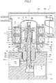
Fig. 1] Fig. 1 is a longitudinal sectional view of an electric valve according to a first embodiment of the present invention. - [
Fig. 2] Fig. 2 is a longitudinal sectional view of an electric valve according to a second embodiment of the present invention. - [
Fig. 3] Fig. 3 is a longitudinal sectional view of an electric valve according to a third embodiment of the present invention. - An electric valve according to a first embodiment of the present invention is described below with reference to
Fig. 1 . The electric valve 1 according to the present embodiment is, for example, used for adjusting the flow rate of refrigerant in a refrigeration cycle or the like. Electric valves according to a second embodiment and a third embodiment are used for the same purpose as the electric valve according to the first embodiment.Fig. 1 is a sectional view (longitudinal sectional view) along an axis of the electric valve according to the first embodiment of the present invention. - As illustrated in
Fig. 1 , the electric valve 1 includes avalve body 10, aflange member 20, acan 30, adriving mechanism 40, avalve element 50, astator unit 60, and asealing member 70. - The
valve body 10 is made of, for example, metal such as brass or aluminum alloy. Thevalve body 10 integrally includes amain body portion 11 in a round columnar shape and acylindrical portion 12. Thecylindrical portion 12 protrudes upward from anupper surface 11a of the main body portion 11 (i.e., a surface of the valve body 10). Avalve chamber 13 is provided inside themain body portion 11. Aconduit 14 is attached to themain body portion 11 and extends to the left inFig. 1 . Aconduit 15 is attached to themain body portion 11 and extends downward inFig. 1 . Theconduit 14 is connected to thevalve chamber 13. Theconduit 15 is connected to thevalve chamber 13 via aport 16. An inner space of thecylindrical portion 12 is connected to thevalve chamber 13. - The
flange member 20 is made of, for example, metal such as stainless steel. Theflange member 20 has an annular plate shape. An innerperipheral edge 20a of theflange member 20 is joined to an upper end of thecylindrical portion 12 of thevalve body 10 by brazing or other means. - The
upper surface 11a of themain body portion 11 of thevalve body 10, an outercircumferential surface 12a of thecylindrical portion 12, and alower surface 20c of theflange member 20 form agroove 25 in an annular recess shape. - The
can 30 is made of, for example, metal such as stainless steel. Thecan 30 has a cylindrical shape with its upper end closed. Thelower end 30a of thecan 30 is joined to an outerperipheral edge 20b of theflange member 20 by welding or other means. Thedriving mechanism 40 is disposed in thecan 30. - The
driving mechanism 40 drives thevalve element 50 in an up-and-down direction (an open-and-close direction). Thedriving mechanism 40 includes arotor 41, avalve shaft holder 42, aguide bush 43, and avalve shaft 44. - The
rotor 41 has a substantially cylindrical shape. An outer diameter of therotor 41 is slightly smaller than an inner diameter of thecan 30. Therotor 41 includes a permanent magnet. Therotor 41 is rotatably disposed in thecan 30. - The
valve shaft holder 42 has a cylindrical shape with its upper end closed. Asupport ring 45 is fixed to the upper end of thevalve shaft holder 42 by caulking. Therotor 41 and thevalve shaft holder 42 are integrally coupled via the supportingring 45. Aninternal thread portion 42c is formed on an inner circumferential surface of thevalve shaft holder 42. - The
guide bush 43 integrally includes a large-diametercylindrical portion 43a and a small-diametercylindrical portion 43b. The small-diametercylindrical portion 43b is coaxially connected to an upper end of the large-diametercylindrical portion 43a. An outer diameter of the large-diametercylindrical portion 43a is larger than an outer diameter of the small-diametercylindrical portion 43b. Anexternal thread portion 43c is formed on an outer circumferential surface of the small-diametercylindrical portion 43b. Theexternal thread portion 43c is screwed into theinternal thread portion 42c of thevalve shaft holder 42. The large-diametercylindrical portion 43a is press-fitted inside thecylindrical portion 12 of thevalve body 10. Theguide bush 43 and thevalve body 10 are integrally coupled. - The
valve shaft 44 includes astem body 44a in a round columnar shape and an upper small-diameter portion 44b in a round columnar shape. The upper small-diameter portion 44b is coaxially connected to an upper end of thestem body 44a. A diameter of the upper small-diameter portion 44b is smaller than a diameter of thestem body 44a. The upper small-diameter portion 44b is extended through thevalve shaft holder 42. Apush nut 46, which is a retainer, is attached to the upper small-diameter portion 44b. Thevalve shaft 44 includes a step portion between thestem body 44a and the upper small-diameter portion 44b. Acompression coil spring 47 is disposed between the step portion and thevalve shaft holder 42. Thevalve shaft 44 is pushed downward by thecompression coil spring 47. - An
upper stopper member 48 is attached to thevalve shaft holder 42. Alower stopper member 49 is attached to the large-diametercylindrical portion 43a of theguide bush 43. When thevalve shaft holder 42 rotates and reaches a lower limit position, theupper stopper member 48 comes into contact with thelower stopper member 49 and further rotation of thevalve shaft holder 42 is restricted. - The
valve element 50 is integrally formed at a lower end of thevalve shaft 44. Thevalve element 50 is driven by thedriving mechanism 40 to move in the up-and-down direction. Thevalve element 50 opens and closes theport 16 that is open to thevalve chamber 13. - The
stator unit 60 includes afitting hole 60a. Thecan 30 is fitted into thefitting hole 60a. Thestator unit 60 is disposed on an outside of thecan 30. Thestator unit 60 includes astator 61 and amold 62 that is made of synthetic resin. - The
stator 61 includes ayoke 61a, abobbin 61b, and acoil 61c. Thecoil 61c is wound around theyoke 61a via thebobbin 61b. Thestator 61 has a configuration including twocoils 61c, which are upper and lower coils. Thestator 61 and therotor 41 constitute a stepping motor. - The
mold 62 is disposed to cover thestator 61. Themold 62 includes atubular portion 63 in a cylindrical shape. Thetubular portion 63 protrudes toward thevalve body 10. Thetubular portion 63 has an inner diameter that is the same as an outer diameter of themain body portion 11 of thevalve body 10. Thetubular portion 63 is disposed to surround thegroove 25. Themain body portion 11 of thevalve body 10 is fitted inside a lower end of thetubular portion 63. - The sealing
member 70 is an O-ring in a circular shape. The sealingmember 70 is made of an elastic material such as a rubber material. The sealingmember 70 is disposed in thegroove 25. Thegroove 25 is formed in an annular shape by theupper surface 11a of themain body portion 11 of thevalve body 10, the outercircumferential surface 12a of thecylindrical portion 12, and thelower surface 20c of theflange member 20. The sealingmember 70 is held (disposed in a compressed state) between the outercircumferential surface 12a of thecylindrical portion 12 of thevalve body 10 and an innercircumferential surface 63a of thetubular portion 63 of thestator unit 60. The sealingmember 70 inhibits water from entering thefitting hole 60a of thestator unit 60. In the present embodiment, the sealingmember 70 is in contact with theupper surface 11a of themain body portion 11 of thevalve body 10. - In the electric valve 1, the axes of the valve body 10 (the
body portion 11 and the cylindrical portion 12), theport 16, thecan 30, therotor 41, thevalve shaft holder 42, theguide bush 43, thevalve shaft 44, thevalve element 50, thestator 61, and thetubular portion 63 are coincident with an axis L. In other words, they are all coaxially disposed. - The operation of the electric valve 1 is described below.
- In the electric valve 1, a current is applied to the
coil 61c to rotate therotor 41 in one direction. Thevalve shaft holder 42 rotates together with therotor 41. The screw feed action between theinternal thread portion 42c of thevalve shaft holder 42 and theexternal thread portion 43c of theguide bush 43 moves thevalve shaft holder 42 downward. Thevalve shaft 44 moves downward together with thevalve shaft holder 42, and thevalve element 50 closes theport 16. - In the electric valve 1, a current is applied to the
coil 61c to rotate therotor 41 in the other direction. Thevalve shaft holder 42 rotates together with therotor 41. The screw feed action between theinternal thread portion 42c of thevalve shaft holder 42 and theexternal thread portion 43c of theguide bush 43 moves thevalve shaft holder 42 upward. Thevalve shaft 44 moves upward together with thevalve shaft holder 42, and thevalve element 50 opens theport 16. - In the manner described above, according to the electric valve 1 in the present embodiment, the
upper surface 11a of thevalve body 10, thecylindrical portion 12 of thevalve body 10, and theflange member 20 form thegroove 25 in the annular recess shape. Thestator unit 60 includes thetubular portion 63 that surrounds thegroove 25. The sealingmember 70 is disposed in thegroove 25 and held between thecylindrical portion 12 of thevalve body 10 and thetubular portion 63 of thestator unit 60. With this configuration, the sealingmember 70 can be disposed in the electric valve 1 without an annular recessed groove machined on the outercircumferential surface 12a of thecylindrical portion 12 of thevalve body 10, or without a supporting member for the sealingmember 70. Thus, manufacturing processes for and members in the electric valve 1 can be reduced. Therefore, it is possible to inhibit, with a small in size and inexpensive configuration, corrosion and rust caused by water entering. - An electric valve according to a second embodiment of the present invention is described below with reference to
Fig. 2. Fig. 2 is a sectional view (longitudinal view) along an axis of the electric valve according to the second embodiment of the present invention. - As illustrated in
Fig. 2 , anelectric valve 2 according to the second embodiment includes avalve body 10A, aflange member 20, acan 30, adriving mechanism 40, avalve element 50, astator unit 60A, and a sealingmember 70. - The
electric valve 2 has the same (including substantially the same) configuration as the electric valve 1 according to the above first embodiment except for thevalve body 10A and thestator unit 60A. Thevalve body 10A and thestator unit 60A have different configurations from those of the electric valve 1. In the following description, elements that are the same as those of the first embodiment are denoted by corresponding reference signs, and descriptions of these elements are omitted. - The
valve body 10A is made of, for example, metal such as aluminum alloy. Thevalve body 10A includes amain body portion 11A in a rectangular parallelepiped shape and acylindrical portion 12A. Thecylindrical portion 12A protrudes upward from anupper surface 11a of themain body portion 11A (i.e., a surface of thevalve body 10A). Avalve chamber 13 is provided inside themain body portion 11A. Aflow channel 17 is provided in themain body portion 11A and extends to the left inFig. 2 . Aflow channel 18 is provided in themain body portion 11A and extends to the right inFig. 2 . Theflow channel 17 is connected to thevalve chamber 13. Theflow channel 18 is connected to thevalve chamber 13 via aport 19. - An
external thread portion 12b is provided on a part of an outercircumferential surface 12a of thecylindrical portion 12A. Aninternal thread portion 11b is provided on themain body portion 11A. Theinternal thread portion 11b is formed so as to open on theupper surface 11a. Theexternal thread portion 12b is screwed into theinternal thread portion 11b. Thus, themain body portion 11A and thecylindrical portion 12A are integrally coupled. An inner space of thecylindrical portion 12A is connected to thevalve chamber 13. - The
stator unit 60A includes afitting hole 60a. Thecan 30 is fitted into thefitting hole 60a. Thestator unit 60A is disposed on the outside of thecan 30. Thestator unit 60A includes astator 61 and acase 62A. - The
case 62A is disposed to accommodate thestator 61 in its inner space. Thecase 62A includes atubular portion 63A in a cylindrical shape. Thetubular portion 63A protrudes toward thevalve body 10A. Thetubular portion 63A is disposed to surround thegroove 25 in the annular shape. A lower end potion of thetubular portion 63A is in contact with theupper surface 11a of themain body portion 11A of thevalve body 10A. An innercircumferential surface 63b of thetubular portion 63A is a tapered surface. The innercircumferential surface 63b defines an inner diameter of thetubular portion 63A, the inner diameter increasing in a direction from theflange member 20 toward theupper surface 11a. - The
electric valve 2 of the second embodiment also has the functions and effects similar to or the same as those of the electric valve 1 of the first embodiment described above. - The
electric valve 2 includes theexternal thread portion 12b that is provided on the outercircumferential surface 12a of thecylindrical portion 12A of themain valve body 10A. Theinternal thread portion 11b into which theexternal thread portion 12b is screwed is formed so as to open on theupper surface 11a of themain body portion 11A of thevalve body 10A. The sealingmember 70 is in contact with theupper surface 11a of themain body portion 11A of thevalve body 10A. With this configuration, the sealingmember 70 can inhibit water from entering a point at which theexternal thread portion 12b is screwed into theinternal thread portion 11b. - The
tubular portion 63A of thestator unit 60A includes the innercircumferential surface 63b defining the inner diameter of thetubular portion 63A, the inner diameter increasing in a direction from theflange member 20 toward theupper surface 11a of themain body portion 11A of thevalve body 10A. With this configuration, when thecan 30 is inserted inside thestator unit 60A and thetubular portion 63A of thestator unit 60A is disposed to surround thegroove 25 in the annular shape, the innercircumferential surface 63b of thetubular portion 63A can push the sealingmember 70 toward theupper surface 11a of themain body portion 11A of thevalve body 10A, and the sealingmember 70 can be pressed against theupper surface 11a. Therefore, the sealingmember 70 can more effectively inhibit water from entering the point at which theexternal thread portion 12b is screwed into theinternal thread portion 11b. - An electric valve according to a third embodiment of the present invention is described below with reference to
Fig. 3. Fig. 3 is a sectional view (longitudinal sectional view) along an axis of the electric valve according to the third embodiment of the present invention. - As illustrated in
Fig. 3 , anelectric valve 3 according to the third embodiment includes avalve body 10B, aflange member 20, acan 30, adriving mechanism 40B, avalve element 50B, astator unit 60B, and a sealingmember 70. - The
electric valve 3 has the same (including substantially the same) configuration as the electric valve 1 according to the above first embodiment except for thevalve body 10B, thedriving mechanism 40B, thevalve element 50B, and thestator unit 60B. Thevalve body 10B, thedriving mechanism 40B, thevalve element 50B, and thestator unit 60B have different configurations from those of the electric valve 1. In the following description, elements that are the same as those of the first embodiment are denoted by corresponding reference signs, and descriptions of these elements are omitted. - The
valve body 10B is made of, for example, metal such as aluminum alloy. Thevalve body 10B includes amain body portion 11B in a rectangular parallelepiped shape and acylindrical portion 12B. Thecylindrical portion 12B protrudes upward from anupper surface 11a of themain body portion 11B (i.e., a surface of thevalve body 10B). Avalve chamber 13 is provided inside themain body portion 11B. Aflow channel 17 is provided in themain body portion 11B and extends to the left inFig. 3 . Aflow channel 18 is provided in themain body portion 11B and extends to the right inFig. 3 . Theflow channel 17 is connected to thevalve chamber 13. Theflow channel 18 is connected to thevalve chamber 13 via aport 19. - An
external thread portion 12b is provided on a part of an outercircumferential surface 12a of thecylindrical portion 12B. Aninternal thread portion 11b is provided on themain body portion 11B. Theinternal thread portion 11b is formed so as to open on theupper surface 11a. Theexternal thread portion 12b is screwed into theinternal thread portion 11b. Thus, themain body portion 11B and thecylindrical portion 12B are integrally coupled. An inner space of thecylindrical portion 12B is connected to thevalve chamber 13. - The
driving mechanism 40B drives thevalve element 50B in an up-and-down direction (an open-and-close direction). Thedriving mechanism 40B includes arotor 81, aplanetary gear mechanism 85, aguide member 95, anelevation shaft 96, aball 97, andvalve opening spring 98. - The
rotor 81 has a substantially cylindrical shape. An outer diameter of therotor 81 is slightly smaller than an inner diameter of thecan 30. Therotor 81 includes a permanent magnet. Therotor 81 is rotatably disposed in thecan 30. An upper end of therotor 81 and arotor shaft 83 are integrally coupled via arotor supporting member 82. Therotor 81 and thestator 61 of thestator unit 60B described later constitute a stepping motor. - The
planetary gear mechanism 85 is disposed inside therotor 81. Theplanetary gear mechanism 85 includes asun gear 86, a fixedring gear 87, a plurality ofplanetary gears 88, acarrier 89, anoutput gear 90, anoutput shaft 91, and agear case 92. Thesun gear 86 is integral with therotor supporting member 82. The fixedring gear 87 is an internal gear. The fixedring gear 87 is fixed to an upper end of thegear case 92 in a cylindrical shape. Theplanetary gears 88 are disposed between thesun gear 86 and the fixedring gear 87. Theplanetary gears 88 mesh with thesun gear 86 and the fixedring gear 87. Thecarrier 89 rotatably supports the plurality of the planetary gears 88. Theoutput gear 90 has a bottomed cylindrical shape. Theoutput gear 90 is an internal gear. Theoutput gear 90 surrounds the plurality of theplanetary gears 88 and meshes with them. Theoutput shaft 91 has an upper portion that is fixed, by press-fitting or other means, into a hole formed in a bottom portion of theoutput gear 90. Thegear case 92 is attached to an upper end of thecylindrical portion 12B of thevalve body 10B. - The
guide member 95 has a cylindrical shape and disposed in the upper end of thecylindrical portion 12B of thevalve body 10B. Aninternal thread portion 95a is provided on an inner circumferential surface of theguide member 95. - The
elevation shaft 96 has a round columnar shape. Anexternal thread portion 96a is provided on an outer circumferential surface of theelevation shaft 96. Theexternal thread portion 96a is screwed into theinternal thread portion 95a of theguide member 95. Aflat plate portion 96b protrudes upward from an upper end surface of theelevation shaft 96. Theoutput shaft 91 of theplanetary gear mechanism 85 includes aslit 91a. Theflat plate portion 96b is inserted into theslit 91a in such a manner as to be movable in the up-and-down direction. Theelevation shaft 96 is rotated together with rotation of theoutput shaft 91. The screw feed action between theexternal thread portion 96a and theinternal thread portion 95a moves theelevation shaft 96 in the up-and-down direction. - The
ball 97 is disposed between theelevation shaft 96 and thevalve element 50B. Thevalve opening spring 98 is a compression coil spring. Thevalve opening spring 98 is disposed between thevalve element 50B and thevalve body 10B. - The
valve element 50B has a substantially round columnar shape. A lower end of thevalve element 50B faces theport 19 in the up-and-down direction. An upper end of thevalve element 50B is connected to theelevation shaft 96 via theball 97. Thevalve element 50B is pushed upward by thevalve opening spring 98. - The
stator unit 60B includes afitting hole 60a. Thecan 30 is fitted into thefitting hole 60a. Thestator unit 60B is disposed on the outside of thecan 30. Thestator unit 60B includes thestator 61 and amold 62B that is made of synthetic resin. - The
mold 62B is disposed to cover thestator 61. Themold 62B includes atubular portion 63B in a cylindrical shape. Thetubular portion 63B protrudes toward thevalve body 10B. Thetubular portion 63B is disposed to surround thegroove 25 in the annular shape. A lower end potion of thetubular portion 63B is in contact with theupper surface 11a of themain body portion 11B of thevalve body 10B. An innercircumferential surface 63b of thetubular portion 63B is a tapered surface. The innercircumferential surface 63b defines an inner diameter of thetubular portion 63B, the inner diameter increasing in a direction from the flange member20 toward theupper surface 11a. - The operation of the
electric valve 3 is described below. - In the
electric valve 3, a current is applied to thecoil 61c to rotate therotor 81 in one direction. When therotor 81 rotates, theelevation shaft 96 rotates together with theoutput shaft 91 of theplanetary gear mechanism 85. The screw feed action between theexternal thread portion 96a of theelevation shaft 96 and theinternal thread portion 95a of theguide member 95 moves theelevation shaft 96 downward. Thevalve element 50B is pushed downward by theelevation shaft 96, and thevalve element 50B closes theport 19. - In the
electric valve 3, a current is applied to thecoil 61c to rotate therotor 81 in the other direction. When therotor 81 rotates, theelevation shaft 96 rotates together with theoutput shaft 91 of theplanetary gear mechanism 85. The screw feed action between theexternal thread portion 96a of theelevation shaft 96 and theinternal thread portion 95a of theguide member 95 moves theelevation shaft 96 upward. When theelevation shaft 96 moves upward, thevalve element 50B is pushed upward by thevalve opening spring 98, and thevalve element 50B opens theport 19. - The
electric valve 3 of the third embodiment also has the functions and effects similar to or the same as those of theelectric valve 2 of the second embodiment described above. - Although the embodiments of the present invention have been described above, the present invention is not limited to these embodiments. Addition and removal of components and design changes may be suitably made to the above-described embodiments by those skilled in the art, and other embodiments obtained by suitably combining features of the above-described embodiments are also within the scope of the present invention as long as they not contrary to the gist of the present invention.
- 1 ... electric valve, 10 ... valve body, 11 ... main body portion, 11a ... upper surface, 12 ... cylindrical portion, 12a ... outer circumferential surface, 13 ... valve chamber, 14, 15 ... conduit, 16 ... port, 20 ... flange member, 20a ... inner peripheral edge, 20b ... outer peripheral edge, 20c ... lower surface, 25 ... groove, 30 ... can, 30a ... lower end, 40 ... driving mechanism, 41 ... rotor, 42 ... valve shaft holder, 42c ... internal thread portion, 43 ... guide bush, 43a ... large-diameter cylindrical portion, 43b ... small-diameter cylindrical portion, 43c ... external thread portion, 44 ... valve shaft, 44a ... stem body, 44b ... upper small-diameter portion, 45 ... supporting ring, 46 ... push nut, 47 ... compression coil spring, 48 ... upper stopper member, 49 ... lower stopper member, 50 ... valve element, 60 ... stator unit, 60a ... fitting hole, 61 ... stator, 61a ... yoke, 61b ... bobbin, 61c ... coil, 62 ... mold, 63 ... tubular portion, 63a ... inner circumferential surface, 70 ... sealing member, L ... axis,
- 2 ... electric valve, 10A ... valve body, 11A ... main body portion, 11b ... internal thread portion, 12A ... cylindrical portion, 12b ... external thread portion, 17, 18 ... flow channel, 19 ... port, 60A ... stator unit, 62A ... case, 63A ... tubular portion, 63b ... inner circumferential surface,
- 3 ... electric valve, 10B ... valve body, 11B ... main body portion, 11b ... internal thread portion, 12B ... cylindrical portion, 12b ... external thread portion, 17, 18 ... flow channel, 19 ... port, 40B ... driving mechanism, 50B ... valve element, 60B ... stator unit, 62B ... mold, 63B ... tubular portion, 63b ... inner circumferential surface, 81 ... rotor, 82 ... rotor supporting member, 83 ... rotor shaft, 85 ... planetary gear mechanism, 86 ... sun gear, 87 ... fixed ring gear, 88 ... planetary gear, 89 ... carrier, 90 ... output gear, 91 ... output shaft, 91a ... slit, 92 ... gear case, 95 ... guide member, 95a ... internal thread portion, 96 ... elevation shaft, 96a ... external thread portion, 96b ... flat plate portion, 97 ... ball, 98 ... valve opening spring
Claims (3)
- An electric valve comprising:a valve body including a valve chamber;a flange member in a circular shape whose inner peripheral edge is attached to a cylindrical portion protruding from a surface of the valve body;a can in a cylindrical shape attached to an outer peripheral edge of the flange member;a rotor disposed in the can;a valve element driven by rotation of the rotor to open and close a port in the valve chamber; anda stator unit attached on an outside of the can,wherein the surface of the valve body, the cylindrical portion of the valve body, and the flange member form a groove in an annular recess shape,wherein the stator unit includes a tubular portion that surrounds the groove, andwherein a sealing member in an annular shape is disposed in the groove and held between the cylindrical portion of the valve body and the tubular portion of the stator unit.
- The electric valve according to Claim 1,wherein an external thread portion is formed on an outer circumferential surface of the cylindrical portion of the valve body,wherein an internal thread portion into which the external thread portion is screwed is formed so as to open on the surface of the valve body, andwherein the sealing member is disposed in contact with the surface of the valve body.
- The electric valve according to Claim 2, wherein the tubular portion of the stator unit includes an inner circumferential surface defining an inner diameter of the tubular portion, the inner diameter increasing in a direction from the flange member toward the surface of the valve body.
Applications Claiming Priority (2)
| Application Number | Priority Date | Filing Date | Title |
|---|---|---|---|
| JP2019196480A JP7176752B2 (en) | 2019-10-29 | 2019-10-29 | electric valve |
| PCT/JP2020/037676 WO2021085038A1 (en) | 2019-10-29 | 2020-10-05 | Electric valve |
Publications (3)
| Publication Number | Publication Date |
|---|---|
| EP4053442A1 true EP4053442A1 (en) | 2022-09-07 |
| EP4053442A4 EP4053442A4 (en) | 2023-11-29 |
| EP4053442B1 EP4053442B1 (en) | 2025-06-11 |
Family
ID=75714004
Family Applications (1)
| Application Number | Title | Priority Date | Filing Date |
|---|---|---|---|
| EP20883337.6A Active EP4053442B1 (en) | 2019-10-29 | 2020-10-05 | Electric valve |
Country Status (6)
| Country | Link |
|---|---|
| US (2) | US11913565B2 (en) |
| EP (1) | EP4053442B1 (en) |
| JP (2) | JP7176752B2 (en) |
| KR (1) | KR102605745B1 (en) |
| CN (2) | CN118224365A (en) |
| WO (1) | WO2021085038A1 (en) |
Families Citing this family (8)
| Publication number | Priority date | Publication date | Assignee | Title |
|---|---|---|---|---|
| JP1694562S (en) * | 2021-03-30 | 2021-09-13 | ||
| JP7383328B2 (en) * | 2021-04-30 | 2023-11-20 | 株式会社不二工機 | electric valve |
| JP7233757B2 (en) * | 2021-06-14 | 2023-03-07 | 株式会社不二工機 | electric valve |
| JP7418838B2 (en) * | 2021-06-14 | 2024-01-22 | 株式会社不二工機 | Stator unit, electric valve, and method for manufacturing the stator unit |
| CN118974461A (en) * | 2022-04-21 | 2024-11-15 | 株式会社不二工机 | Electric valve |
| WO2024111459A1 (en) | 2022-11-22 | 2024-05-30 | 株式会社ダイセル | Polyurethane resin |
| JP7846653B2 (en) * | 2023-09-06 | 2026-04-15 | 株式会社鷺宮製作所 | Valve device |
| WO2025105044A1 (en) * | 2023-11-17 | 2025-05-22 | 株式会社不二工機 | Motorized valve |
Family Cites Families (35)
| Publication number | Priority date | Publication date | Assignee | Title |
|---|---|---|---|---|
| US3757263A (en) * | 1972-07-24 | 1973-09-04 | Richdel | Solenoid valve operator |
| JPS5249634B2 (en) | 1973-01-22 | 1977-12-19 | ||
| US4501297A (en) * | 1982-04-08 | 1985-02-26 | Automatic Switch Company | Rotary valve |
| JP2755538B2 (en) * | 1992-11-30 | 1998-05-20 | 株式会社不二工機 | Electric flow control valve |
| JPH1163274A (en) * | 1997-08-20 | 1999-03-05 | Fuji Koki Corp | Motor-driven valve |
| JP3937029B2 (en) * | 1999-03-26 | 2007-06-27 | 株式会社鷺宮製作所 | Motorized valve |
| US6460567B1 (en) * | 1999-11-24 | 2002-10-08 | Hansen Technologies Corpporation | Sealed motor driven valve |
| JP4550528B2 (en) * | 2004-09-01 | 2010-09-22 | 株式会社不二工機 | Motorized valve |
| JP4781010B2 (en) * | 2005-05-19 | 2011-09-28 | 株式会社不二工機 | Motorized valve |
| JP2008169910A (en) * | 2007-01-11 | 2008-07-24 | Fuji Koki Corp | Motor-operated valve |
| JP2008267464A (en) * | 2007-04-18 | 2008-11-06 | Fuji Koki Corp | Motor driven valve |
| JP5022120B2 (en) * | 2007-07-03 | 2012-09-12 | 株式会社不二工機 | Motorized valves for air conditioning systems |
| JP5249634B2 (en) * | 2008-05-29 | 2013-07-31 | 株式会社不二工機 | Flow control valve |
| EP2211077B1 (en) * | 2009-01-22 | 2016-10-19 | Fujikoki Corporation | Motor-driven valve |
| KR200463508Y1 (en) * | 2010-08-04 | 2012-11-07 | (주)팜코 | 3 port piezoelectric valve |
| JP5693900B2 (en) * | 2010-09-15 | 2015-04-01 | 株式会社不二工機 | Motorized valve |
| JP5693899B2 (en) | 2010-09-15 | 2015-04-01 | 株式会社不二工機 | Motorized valve |
| JP5618722B2 (en) * | 2010-09-16 | 2014-11-05 | 株式会社クボタ | Sealing members, pipe fittings and water intake piping |
| JP5130339B2 (en) * | 2010-10-05 | 2013-01-30 | 株式会社鷺宮製作所 | Motorized valve |
| JP2012172749A (en) * | 2011-02-21 | 2012-09-10 | Fuji Koki Corp | Valve apparatus |
| JP5982168B2 (en) | 2012-04-24 | 2016-08-31 | 株式会社不二工機 | Motorized valve |
| JP5397842B1 (en) * | 2012-09-28 | 2014-01-22 | 三浦工業株式会社 | Flow control valve |
| JP2014196810A (en) * | 2013-03-29 | 2014-10-16 | 株式会社テージーケー | Stepping motor driven control valve |
| JP2016038087A (en) * | 2014-08-11 | 2016-03-22 | エルテック株式会社 | Motor-operated valve |
| JP2016080115A (en) | 2014-10-21 | 2016-05-16 | 株式会社鷺宮製作所 | Fluid control valve |
| JP6481155B2 (en) * | 2014-11-25 | 2019-03-13 | 株式会社テージーケー | Motorized valve |
| JP6392685B2 (en) * | 2015-03-06 | 2018-09-19 | 株式会社鷺宮製作所 | Motorized valve |
| JP6526478B2 (en) * | 2015-05-18 | 2019-06-05 | 株式会社不二工機 | Motorized valve |
| JP6505151B2 (en) * | 2017-03-23 | 2019-04-24 | 株式会社不二工機 | Flow control valve |
| JP6518713B2 (en) * | 2017-04-12 | 2019-05-22 | 株式会社不二工機 | Motorized valve |
| CN109424777B (en) * | 2017-08-24 | 2025-08-08 | 浙江三花智能控制股份有限公司 | Electric valve |
| CN109869488B (en) * | 2017-12-01 | 2021-10-01 | 浙江三花智能控制股份有限公司 | Electronic expansion valve and refrigeration system having the same |
| WO2019187866A1 (en) | 2018-03-26 | 2019-10-03 | 株式会社不二工機 | Electrically operated valve |
| JP6584564B2 (en) | 2018-03-27 | 2019-10-02 | 株式会社不二工機 | Motorized valve |
| US10948099B2 (en) * | 2019-02-14 | 2021-03-16 | Tgk Co., Ltd. | Motor operated valve |
-
2019
- 2019-10-29 JP JP2019196480A patent/JP7176752B2/en active Active
-
2020
- 2020-10-05 CN CN202410375182.4A patent/CN118224365A/en active Pending
- 2020-10-05 CN CN202080068216.5A patent/CN114585840B/en active Active
- 2020-10-05 WO PCT/JP2020/037676 patent/WO2021085038A1/en not_active Ceased
- 2020-10-05 US US17/754,834 patent/US11913565B2/en active Active
- 2020-10-05 KR KR1020227010777A patent/KR102605745B1/en active Active
- 2020-10-05 EP EP20883337.6A patent/EP4053442B1/en active Active
-
2022
- 2022-10-24 JP JP2022169590A patent/JP7427275B2/en active Active
-
2024
- 2024-01-09 US US18/408,161 patent/US12104709B2/en active Active
Also Published As
| Publication number | Publication date |
|---|---|
| US20240026988A1 (en) | 2024-01-25 |
| JP7427275B2 (en) | 2024-02-05 |
| EP4053442A4 (en) | 2023-11-29 |
| US11913565B2 (en) | 2024-02-27 |
| US12104709B2 (en) | 2024-10-01 |
| CN114585840A (en) | 2022-06-03 |
| KR102605745B1 (en) | 2023-11-24 |
| CN118224365A (en) | 2024-06-21 |
| JP2022186853A (en) | 2022-12-15 |
| KR20220051397A (en) | 2022-04-26 |
| CN114585840B (en) | 2024-04-19 |
| EP4053442B1 (en) | 2025-06-11 |
| JP7176752B2 (en) | 2022-11-22 |
| WO2021085038A1 (en) | 2021-05-06 |
| US20240151320A1 (en) | 2024-05-09 |
| JP2021071136A (en) | 2021-05-06 |
Similar Documents
| Publication | Publication Date | Title |
|---|---|---|
| EP4053442B1 (en) | Electric valve | |
| KR102408886B1 (en) | Valve Core Assembly | |
| JP6574467B2 (en) | Direct-acting motor-operated valve and mounting method thereof | |
| EP3690295A1 (en) | Motor-operated valve | |
| KR101165317B1 (en) | Electrically operated valve | |
| EP3273186B1 (en) | Motor-operated valve | |
| CN113324054B (en) | Electric valve | |
| EP1632703A1 (en) | Motor-operated valve | |
| CN105937644A (en) | Electrically operated valve | |
| EP3418613A1 (en) | Electric valve | |
| EP3392536B1 (en) | Control valve and method of manufacturing the same | |
| US20220154851A1 (en) | Electronic Expansion Valve and Refrigeration System | |
| EP2535626A1 (en) | Solenoid device | |
| CN105937632B (en) | Motor-driven valve | |
| JP5380562B2 (en) | Motorized valve | |
| EP3929476B1 (en) | Flow rate control valve | |
| JP2023168434A (en) | Motor-operated valve and refrigeration cycle system | |
| EP4671585A1 (en) | ELECTRIC VALVE | |
| JP2017223372A (en) | Motor-driven valve | |
| CN120608961A (en) | Valve units and valve devices | |
| CN220204834U (en) | Electric valve | |
| JP2025163550A (en) | Valve gear and valve gear unit | |
| EP4145031A1 (en) | Valve device | |
| CN121953086A (en) | Valve device | |
| WO2025062733A1 (en) | Electric valve |
Legal Events
| Date | Code | Title | Description |
|---|---|---|---|
| STAA | Information on the status of an ep patent application or granted ep patent |
Free format text: STATUS: THE INTERNATIONAL PUBLICATION HAS BEEN MADE |
|
| PUAI | Public reference made under article 153(3) epc to a published international application that has entered the european phase |
Free format text: ORIGINAL CODE: 0009012 |
|
| STAA | Information on the status of an ep patent application or granted ep patent |
Free format text: STATUS: REQUEST FOR EXAMINATION WAS MADE |
|
| 17P | Request for examination filed |
Effective date: 20220330 |
|
| AK | Designated contracting states |
Kind code of ref document: A1 Designated state(s): AL AT BE BG CH CY CZ DE DK EE ES FI FR GB GR HR HU IE IS IT LI LT LU LV MC MK MT NL NO PL PT RO RS SE SI SK SM TR |
|
| DAV | Request for validation of the european patent (deleted) | ||
| DAX | Request for extension of the european patent (deleted) | ||
| A4 | Supplementary search report drawn up and despatched |
Effective date: 20231031 |
|
| RIC1 | Information provided on ipc code assigned before grant |
Ipc: F16K 31/04 20060101AFI20231025BHEP |
|
| GRAP | Despatch of communication of intention to grant a patent |
Free format text: ORIGINAL CODE: EPIDOSNIGR1 |
|
| STAA | Information on the status of an ep patent application or granted ep patent |
Free format text: STATUS: GRANT OF PATENT IS INTENDED |
|
| INTG | Intention to grant announced |
Effective date: 20250128 |
|
| GRAS | Grant fee paid |
Free format text: ORIGINAL CODE: EPIDOSNIGR3 |
|
| GRAA | (expected) grant |
Free format text: ORIGINAL CODE: 0009210 |
|
| STAA | Information on the status of an ep patent application or granted ep patent |
Free format text: STATUS: THE PATENT HAS BEEN GRANTED |
|
| AK | Designated contracting states |
Kind code of ref document: B1 Designated state(s): AL AT BE BG CH CY CZ DE DK EE ES FI FR GB GR HR HU IE IS IT LI LT LU LV MC MK MT NL NO PL PT RO RS SE SI SK SM TR |
|
| REG | Reference to a national code |
Ref country code: GB Ref legal event code: FG4D |
|
| REG | Reference to a national code |
Ref country code: CH Ref legal event code: EP |
|
| REG | Reference to a national code |
Ref country code: IE Ref legal event code: FG4D |
|
| REG | Reference to a national code |
Ref country code: DE Ref legal event code: R096 Ref document number: 602020052749 Country of ref document: DE |
|
| REG | Reference to a national code |
Ref country code: SE Ref legal event code: TRGR |
|
| PG25 | Lapsed in a contracting state [announced via postgrant information from national office to epo] |
Ref country code: FI Free format text: LAPSE BECAUSE OF FAILURE TO SUBMIT A TRANSLATION OF THE DESCRIPTION OR TO PAY THE FEE WITHIN THE PRESCRIBED TIME-LIMIT Effective date: 20250611 Ref country code: ES Free format text: LAPSE BECAUSE OF FAILURE TO SUBMIT A TRANSLATION OF THE DESCRIPTION OR TO PAY THE FEE WITHIN THE PRESCRIBED TIME-LIMIT Effective date: 20250611 |
|
| REG | Reference to a national code |
Ref country code: LT Ref legal event code: MG9D |
|
| PG25 | Lapsed in a contracting state [announced via postgrant information from national office to epo] |
Ref country code: GR Free format text: LAPSE BECAUSE OF FAILURE TO SUBMIT A TRANSLATION OF THE DESCRIPTION OR TO PAY THE FEE WITHIN THE PRESCRIBED TIME-LIMIT Effective date: 20250912 Ref country code: NO Free format text: LAPSE BECAUSE OF FAILURE TO SUBMIT A TRANSLATION OF THE DESCRIPTION OR TO PAY THE FEE WITHIN THE PRESCRIBED TIME-LIMIT Effective date: 20250911 |
|
| REG | Reference to a national code |
Ref country code: NL Ref legal event code: MP Effective date: 20250611 |
|
| PG25 | Lapsed in a contracting state [announced via postgrant information from national office to epo] |
Ref country code: BG Free format text: LAPSE BECAUSE OF FAILURE TO SUBMIT A TRANSLATION OF THE DESCRIPTION OR TO PAY THE FEE WITHIN THE PRESCRIBED TIME-LIMIT Effective date: 20250611 |
|
| PG25 | Lapsed in a contracting state [announced via postgrant information from national office to epo] |
Ref country code: HR Free format text: LAPSE BECAUSE OF FAILURE TO SUBMIT A TRANSLATION OF THE DESCRIPTION OR TO PAY THE FEE WITHIN THE PRESCRIBED TIME-LIMIT Effective date: 20250611 |
|
| PG25 | Lapsed in a contracting state [announced via postgrant information from national office to epo] |
Ref country code: RS Free format text: LAPSE BECAUSE OF FAILURE TO SUBMIT A TRANSLATION OF THE DESCRIPTION OR TO PAY THE FEE WITHIN THE PRESCRIBED TIME-LIMIT Effective date: 20250911 |
|
| PG25 | Lapsed in a contracting state [announced via postgrant information from national office to epo] |
Ref country code: LV Free format text: LAPSE BECAUSE OF FAILURE TO SUBMIT A TRANSLATION OF THE DESCRIPTION OR TO PAY THE FEE WITHIN THE PRESCRIBED TIME-LIMIT Effective date: 20250611 |
|
| PG25 | Lapsed in a contracting state [announced via postgrant information from national office to epo] |
Ref country code: NL Free format text: LAPSE BECAUSE OF FAILURE TO SUBMIT A TRANSLATION OF THE DESCRIPTION OR TO PAY THE FEE WITHIN THE PRESCRIBED TIME-LIMIT Effective date: 20250611 |
|
| PG25 | Lapsed in a contracting state [announced via postgrant information from national office to epo] |
Ref country code: PT Free format text: LAPSE BECAUSE OF FAILURE TO SUBMIT A TRANSLATION OF THE DESCRIPTION OR TO PAY THE FEE WITHIN THE PRESCRIBED TIME-LIMIT Effective date: 20251013 |
|
| REG | Reference to a national code |
Ref country code: AT Ref legal event code: MK05 Ref document number: 1802502 Country of ref document: AT Kind code of ref document: T Effective date: 20250611 |
|
| PG25 | Lapsed in a contracting state [announced via postgrant information from national office to epo] |
Ref country code: IS Free format text: LAPSE BECAUSE OF FAILURE TO SUBMIT A TRANSLATION OF THE DESCRIPTION OR TO PAY THE FEE WITHIN THE PRESCRIBED TIME-LIMIT Effective date: 20251011 |
|
| PGFP | Annual fee paid to national office [announced via postgrant information from national office to epo] |
Ref country code: DE Payment date: 20251028 Year of fee payment: 6 |
|
| PGFP | Annual fee paid to national office [announced via postgrant information from national office to epo] |
Ref country code: GB Payment date: 20251024 Year of fee payment: 6 |
|
| PG25 | Lapsed in a contracting state [announced via postgrant information from national office to epo] |
Ref country code: AT Free format text: LAPSE BECAUSE OF FAILURE TO SUBMIT A TRANSLATION OF THE DESCRIPTION OR TO PAY THE FEE WITHIN THE PRESCRIBED TIME-LIMIT Effective date: 20250611 Ref country code: SM Free format text: LAPSE BECAUSE OF FAILURE TO SUBMIT A TRANSLATION OF THE DESCRIPTION OR TO PAY THE FEE WITHIN THE PRESCRIBED TIME-LIMIT Effective date: 20250611 |
|
| PGFP | Annual fee paid to national office [announced via postgrant information from national office to epo] |
Ref country code: IT Payment date: 20251031 Year of fee payment: 6 |
|
| PGFP | Annual fee paid to national office [announced via postgrant information from national office to epo] |
Ref country code: FR Payment date: 20251027 Year of fee payment: 6 |
|
| PGFP | Annual fee paid to national office [announced via postgrant information from national office to epo] |
Ref country code: SE Payment date: 20251023 Year of fee payment: 6 |
|
| PG25 | Lapsed in a contracting state [announced via postgrant information from national office to epo] |
Ref country code: CZ Free format text: LAPSE BECAUSE OF FAILURE TO SUBMIT A TRANSLATION OF THE DESCRIPTION OR TO PAY THE FEE WITHIN THE PRESCRIBED TIME-LIMIT Effective date: 20250611 |
|
| PG25 | Lapsed in a contracting state [announced via postgrant information from national office to epo] |
Ref country code: PL Free format text: LAPSE BECAUSE OF FAILURE TO SUBMIT A TRANSLATION OF THE DESCRIPTION OR TO PAY THE FEE WITHIN THE PRESCRIBED TIME-LIMIT Effective date: 20250611 |
|
| PG25 | Lapsed in a contracting state [announced via postgrant information from national office to epo] |
Ref country code: EE Free format text: LAPSE BECAUSE OF FAILURE TO SUBMIT A TRANSLATION OF THE DESCRIPTION OR TO PAY THE FEE WITHIN THE PRESCRIBED TIME-LIMIT Effective date: 20250611 |
|
| PG25 | Lapsed in a contracting state [announced via postgrant information from national office to epo] |
Ref country code: SK Free format text: LAPSE BECAUSE OF FAILURE TO SUBMIT A TRANSLATION OF THE DESCRIPTION OR TO PAY THE FEE WITHIN THE PRESCRIBED TIME-LIMIT Effective date: 20250611 |
|
| PG25 | Lapsed in a contracting state [announced via postgrant information from national office to epo] |
Ref country code: RO Free format text: LAPSE BECAUSE OF FAILURE TO SUBMIT A TRANSLATION OF THE DESCRIPTION OR TO PAY THE FEE WITHIN THE PRESCRIBED TIME-LIMIT Effective date: 20250611 |
|
| REG | Reference to a national code |
Ref country code: DE Ref legal event code: R097 Ref document number: 602020052749 Country of ref document: DE |
|
| PG25 | Lapsed in a contracting state [announced via postgrant information from national office to epo] |
Ref country code: DK Free format text: LAPSE BECAUSE OF FAILURE TO SUBMIT A TRANSLATION OF THE DESCRIPTION OR TO PAY THE FEE WITHIN THE PRESCRIBED TIME-LIMIT Effective date: 20250611 |
|
| PLBE | No opposition filed within time limit |
Free format text: ORIGINAL CODE: 0009261 |
|
| STAA | Information on the status of an ep patent application or granted ep patent |
Free format text: STATUS: NO OPPOSITION FILED WITHIN TIME LIMIT |
|
| REG | Reference to a national code |
Ref country code: CH Ref legal event code: L10 Free format text: ST27 STATUS EVENT CODE: U-0-0-L10-L00 (AS PROVIDED BY THE NATIONAL OFFICE) Effective date: 20260423 |