EP4053430A1 - Drive device and motor vehicle - Google Patents
Drive device and motor vehicle Download PDFInfo
- Publication number
- EP4053430A1 EP4053430A1 EP21160844.3A EP21160844A EP4053430A1 EP 4053430 A1 EP4053430 A1 EP 4053430A1 EP 21160844 A EP21160844 A EP 21160844A EP 4053430 A1 EP4053430 A1 EP 4053430A1
- Authority
- EP
- European Patent Office
- Prior art keywords
- gear
- transmission
- coupling
- drive device
- output
- Prior art date
- Legal status (The legal status is an assumption and is not a legal conclusion. Google has not performed a legal analysis and makes no representation as to the accuracy of the status listed.)
- Withdrawn
Links
Images


Classifications
-
- F—MECHANICAL ENGINEERING; LIGHTING; HEATING; WEAPONS; BLASTING
- F16—ENGINEERING ELEMENTS AND UNITS; GENERAL MEASURES FOR PRODUCING AND MAINTAINING EFFECTIVE FUNCTIONING OF MACHINES OR INSTALLATIONS; THERMAL INSULATION IN GENERAL
- F16H—GEARING
- F16H48/00—Differential gearings
- F16H48/05—Multiple interconnected differential sets
-
- B—PERFORMING OPERATIONS; TRANSPORTING
- B60—VEHICLES IN GENERAL
- B60K—ARRANGEMENT OR MOUNTING OF PROPULSION UNITS OR OF TRANSMISSIONS IN VEHICLES; ARRANGEMENT OR MOUNTING OF PLURAL DIVERSE PRIME-MOVERS IN VEHICLES; AUXILIARY DRIVES FOR VEHICLES; INSTRUMENTATION OR DASHBOARDS FOR VEHICLES; ARRANGEMENTS IN CONNECTION WITH COOLING, AIR INTAKE, GAS EXHAUST OR FUEL SUPPLY OF PROPULSION UNITS IN VEHICLES
- B60K1/00—Arrangement or mounting of electrical propulsion units
-
- F—MECHANICAL ENGINEERING; LIGHTING; HEATING; WEAPONS; BLASTING
- F16—ENGINEERING ELEMENTS AND UNITS; GENERAL MEASURES FOR PRODUCING AND MAINTAINING EFFECTIVE FUNCTIONING OF MACHINES OR INSTALLATIONS; THERMAL INSULATION IN GENERAL
- F16H—GEARING
- F16H48/00—Differential gearings
- F16H48/20—Arrangements for suppressing or influencing the differential action, e.g. locking devices
- F16H48/22—Arrangements for suppressing or influencing the differential action, e.g. locking devices using friction clutches or brakes
-
- B—PERFORMING OPERATIONS; TRANSPORTING
- B60—VEHICLES IN GENERAL
- B60K—ARRANGEMENT OR MOUNTING OF PROPULSION UNITS OR OF TRANSMISSIONS IN VEHICLES; ARRANGEMENT OR MOUNTING OF PLURAL DIVERSE PRIME-MOVERS IN VEHICLES; AUXILIARY DRIVES FOR VEHICLES; INSTRUMENTATION OR DASHBOARDS FOR VEHICLES; ARRANGEMENTS IN CONNECTION WITH COOLING, AIR INTAKE, GAS EXHAUST OR FUEL SUPPLY OF PROPULSION UNITS IN VEHICLES
- B60K17/00—Arrangement or mounting of transmissions in vehicles
- B60K17/04—Arrangement or mounting of transmissions in vehicles characterised by arrangement, location, or kind of gearing
- B60K17/06—Arrangement or mounting of transmissions in vehicles characterised by arrangement, location, or kind of gearing of change-speed gearing
- B60K17/08—Arrangement or mounting of transmissions in vehicles characterised by arrangement, location, or kind of gearing of change-speed gearing of mechanical type
-
- B—PERFORMING OPERATIONS; TRANSPORTING
- B60—VEHICLES IN GENERAL
- B60K—ARRANGEMENT OR MOUNTING OF PROPULSION UNITS OR OF TRANSMISSIONS IN VEHICLES; ARRANGEMENT OR MOUNTING OF PLURAL DIVERSE PRIME-MOVERS IN VEHICLES; AUXILIARY DRIVES FOR VEHICLES; INSTRUMENTATION OR DASHBOARDS FOR VEHICLES; ARRANGEMENTS IN CONNECTION WITH COOLING, AIR INTAKE, GAS EXHAUST OR FUEL SUPPLY OF PROPULSION UNITS IN VEHICLES
- B60K1/00—Arrangement or mounting of electrical propulsion units
- B60K2001/001—Arrangement or mounting of electrical propulsion units one motor mounted on a propulsion axle for rotating right and left wheels of this axle
-
- F—MECHANICAL ENGINEERING; LIGHTING; HEATING; WEAPONS; BLASTING
- F16—ENGINEERING ELEMENTS AND UNITS; GENERAL MEASURES FOR PRODUCING AND MAINTAINING EFFECTIVE FUNCTIONING OF MACHINES OR INSTALLATIONS; THERMAL INSULATION IN GENERAL
- F16H—GEARING
- F16H48/00—Differential gearings
- F16H48/06—Differential gearings with gears having orbital motion
- F16H48/10—Differential gearings with gears having orbital motion with orbital spur gears
- F16H2048/106—Differential gearings with gears having orbital motion with orbital spur gears characterised by two sun gears
-
- Y—GENERAL TAGGING OF NEW TECHNOLOGICAL DEVELOPMENTS; GENERAL TAGGING OF CROSS-SECTIONAL TECHNOLOGIES SPANNING OVER SEVERAL SECTIONS OF THE IPC; TECHNICAL SUBJECTS COVERED BY FORMER USPC CROSS-REFERENCE ART COLLECTIONS [XRACs] AND DIGESTS
- Y02—TECHNOLOGIES OR APPLICATIONS FOR MITIGATION OR ADAPTATION AGAINST CLIMATE CHANGE
- Y02T—CLIMATE CHANGE MITIGATION TECHNOLOGIES RELATED TO TRANSPORTATION
- Y02T10/00—Road transport of goods or passengers
- Y02T10/60—Other road transportation technologies with climate change mitigation effect
- Y02T10/62—Hybrid vehicles
Definitions
- the invention relates to a drive device for a motor vehicle, the drive device having a drive motor, a first output, a second output, a power-split first transmission coupled to the drive motor and assigned to the first output, and a power-split second transmission coupled to the drive motor and assigned to the second output .
- the invention also relates to a motor vehicle.
- the document DE 10 2011 102 749 A1 relates to a transmission arrangement for a motor vehicle with a housing, an electric machine and a transmission device.
- the electrical machine has a stator which is fixed to the housing and a rotor which is rotatably mounted relative to the stator.
- the transmission device has a first face-toothed planetary gear and a second face-toothed planetary gear.
- the first spur-toothed planetary gear is connected to the rotor by means of its input shaft and to a first flanged axle shaft by means of its output shaft.
- the second spur-toothed planetary gear is connected by its input shaft to a coupling shaft of the first planetary gear and by its output shaft to a second axle flange shaft.
- the first planetary gear has a first sun gear, a ring gear and a spider.
- the first sun gear forms an input shaft of the first planetary gear which is arranged coaxially to the rotor and is connected to it.
- the ring gear forms a coupling shaft of the first planetary gear.
- the web forms an output shaft arranged and connected coaxially to the rotor and coaxially to the first flanged shaft and carries a simple set of rotatably mounted first planetary gears which mesh with the first sun gear on the one hand and with the first ring gear on the other hand.
- the second planetary gear has a second sun gear and a second carrier.
- the second web is fixed to the housing and carries a simple set of rotatably mounted second planet gears that mesh with the second sun gear.
- the second planetary gear is designed as a simple minus planetary gear with a second ring gear, the second planetary gears of which also mesh with the second ring gear.
- the document DE 10 2014 101 713 A1 relates to an electric portal axle for the electric drive of a motor vehicle.
- the portal axle has two spur gear stages for driving two wheels of the axle.
- the portal axle has a single electric machine, downstream a switchable transmission with freewheel and a differential and a housing.
- the shiftable gear is designed as a planetary gear and has a switching means for shifting two gears of the portal axle. In a first gear, a ring gear of the transmission and a clutch body fixed to the housing are connected and a clutch between the ring gear and a planet carrier of the transmission is open. In a second gear, the ring gear and the clutch body fixed to the housing are separated and the clutch is closed.
- the document DE 10 2017 111 036 A1 relates to a drive device for a motor vehicle.
- the drive device has a drive machine and a transmission device.
- the transmission device has a first and second planetary gear set, each with a plurality of planet gears, and a spur gear differential, each with a plurality of spur gears.
- the spur gear differential is provided to distribute a drive power of the drive machine to a first and second output shaft that is operatively connected to the spur gear differential.
- the planet gears of the first planetary gear set are rotatably arranged on a first planet carrier and mesh with a first sun gear and a first ring gear, the first sun gear being non-rotatably connected to a drive shaft.
- the planet gears of the second planetary gear set are rotatably arranged on a second planet carrier and mesh with a second sun gear and a second ring gear, the second sun gear being non-rotatably connected to the first planet carrier and the first planetary gear set radially inward of the second planetary gear set is nested.
- the respective spur gears of the spur gear differential are rotatably mounted on a common differential carrier, the spur gears of a first spur gear set meshing with a toothing on the first output shaft, and the spur gears of a second spur gear set meshing with a toothing on the second output shaft, and wherein the spur gears of both spur gear sets mesh with each other in pairs.
- the document DE 10 2019 102 940 A1 relates to a power transmission component with a housing.
- the power transmission component includes a planetary carrier disposed within the housing for rotation relative to the housing about a central axis, the planetary carrier having a carrier body and sets of first trunnions, second trunnions and third trunnions, each of the first trunnions surrounding the carrier body is arranged, each of the second pins is arranged around the carrier body, each of the third pins is arranged around the carrier body; an input sun gear disposed in the carrier body so as to be rotatable about the central axis relative to the planetary carrier; a first output sun gear arranged in the carrier body so as to be rotatable about the central axis relative to the planetary carrier.
- the power transmission component includes a second output sun gear, which is arranged in the carrier body such that it is rotatable about the central axis relative to the planetary carrier.
- the power transmission component includes a ring gear that is non-rotatably coupled to the housing.
- the power transmission component includes a plurality of split planetary gears, each of the split planetary gears received in the support body and rotatably mounted on an associated one of the first journals, each of the split planetary gears having a first planetary gear meshed with the input sun gear and a second planetary gear, which is rotatably coupled to the first planetary gear and is in meshing engagement with the ring gear.
- the power transmission component also includes a plurality of third planet gears, each of the third planet gears being rotatably disposed on an associated one of the second trunnions and meshingly engaged with the first output sun gear.
- the power transmission component includes a plurality of fourth planetary gears, each of the fourth planet gears being rotatably mounted on an associated one of the third trunnions and in meshing engagement with the second output sun gear and a corresponding one of the third planet gears.
- the object of the invention is to structurally and/or functionally improve a drive device as mentioned at the outset.
- the invention is based on the object of improving the structure and/or functionality of a motor vehicle as mentioned at the outset.
- the object is achieved with a drive device having the features of claim 1.
- the object is also achieved with a motor vehicle having the features of claim 10.
- Advantageous embodiments and/or developments are the subject matter of the dependent claims.
- the drive device can be used for arrangement in a drive train.
- the drive device can have an input and two outputs.
- the drive device can serve as a differential gear, differential gear, transfer case and/or axle drive.
- the drive device can have a housing.
- the drive motor, the power-split first transmission and the power-split second transmission can be arranged together in the housing.
- the drive motor, the first transmission and the second transmission can additionally be structurally and/or functionally connected to one another.
- the drive device can also be referred to as an integrated drive device.
- the first output can be formed using a first output shaft.
- the second output can be formed using a second output shaft.
- the first output shaft and the second output shaft can/can be rotatably mounted, in particular on the housing.
- the first transmission can have a first power branch between the transmission input and the transmission output and a second power branch between the transmission input and the transmission output on the one hand and the coupling interface on the other hand.
- the first gear can be effective between the drive motor and the first output, between the drive motor and the coupling and/or between the output and the coupling.
- the second transmission can have a first power branch and between the transmission input and the transmission output between the transmission input and the transmission output on the one hand and the coupling interface on the other hand have a second power branch.
- the second gear can be effective between the drive motor and the second output, between the drive motor and the coupling and/or between the output and the coupling.
- axial refers to a direction of extension of the main axis of the drive device. “Axial” then corresponds to a direction of extension of the main axis of the drive device. “Radial” is then a direction that is perpendicular to the direction in which the main axis of the drive device extends and intersects with the main axis of the drive device. “In the circumferential direction” then corresponds to a circular arc direction around the main axis of the drive device.
- the drive motor can serve as a traction drive motor.
- the drive motor can serve as a primary or secondary drive motor.
- the drive motor can be an electric drive machine.
- the electric drive machine can be operated as a motor and/or as a generator.
- the drive motor can be arranged between the first gear and the second gear.
- the drive motor can have a stator and a rotor.
- the stator can be fixed to the housing.
- the drive motor can have a motor shaft.
- the motor shaft can be non-rotatably connected to the rotor.
- the rotor and/or the motor shaft can/can be rotatably mounted, in particular on the housing.
- the motor shaft may have a first end associated with the first gear and a second end associated with the second gear.
- the drive motor can have a motor axis of rotation.
- the first gear and the second gear can each have a main gear axis.
- the axis of rotation of the engine and the main axes of the transmission can be arranged coaxially with one another.
- the axis of rotation of the engine and the main axes of the transmission can form a main axis of the drive device.
- the drive motor can be arranged centrally.
- the first gear and the second gear can be arranged mirror-symmetrically to the drive motor.
- the drive motor can be arranged in the middle be.
- the first gear and the second gear can be arranged on both sides of the drive motor.
- the power-split first transmission and the power-split second transmission can have the same gear ratios.
- the first gear and the second gear can each be constructed in a rotationally symmetrical manner.
- the first gear and the second gear can be constructed mirror-symmetrical to one another.
- the first gear and the second gear can each be designed as a planetary gear.
- the first transmission and the second transmission can each have a motor-side first sun wheel, an output-side second sun wheel and planetary wheels acting between the first sun wheel and the second sun wheel and arranged on a planetary carrier.
- the first sun gears can each form a transmission input.
- the second sun gears can each form a transmission output.
- the first planet carriers can each form a coupling interface.
- the first sun gear of the first transmission can be arranged at the first end of the motor shaft.
- the first sun gear of the second gear can be arranged at the second end of the motor shaft.
- the first sun gears can each be connected to the motor shaft in a torque-proof manner.
- the second sun gear of the first transmission can be arranged on the first output shaft.
- the second sun gear of the first transmission can be connected to the first output shaft in a torque-proof manner.
- the second sun gear of the second transmission can be arranged on the second output shaft.
- the second sun gear of the second transmission can be connected in a rotationally fixed manner to the second output shaft.
- the transmissions can each have at least one first planet gear assigned to the first sun gear and at least one second planet gear assigned to the second sun gear.
- the at least one first planet wheel and the first sun wheel can be arranged in a common plane.
- the at least one second planet wheel and the second sun wheel can be arranged in a common plane.
- the at least one first planetary gear and the at least one second planetary gear can form a pair of planetary gears that are non-rotatably connected to one another.
- a pair of planet gears can be rotatably mounted together on a planet carrier.
- the first gear and the second gear can each have at least one pair of planets, in particular two or three Pairs of planets have.
- the pairs of planets can be distributed, in particular evenly, in the circumferential direction with respect to the main axes of the transmission.
- a first sun gear and a first planetary gear can each have a first gear ratio.
- a second sun gear and a second planetary gear can each have a second gear ratio.
- the planet carriers can each have a toothing.
- the teeth of the planet carrier can be used to couple the gears together.
- the planet carrier of a transmission can be arranged axially between the first sun gear and the second sun gear of this transmission.
- the planet carrier of a transmission can be ring-like or disc-like.
- the planet carrier of a transmission can be arranged axially on the outside of the at least one first planet wheel and axially on the outside of the at least one second planet wheel of this transmission and can encompass the at least one first planet wheel and the at least one second planet wheel radially on the outside.
- the planet carrier of a transmission can be arranged axially between the first sun gear and the second sun gear and axially outside of the at least one first planet gear of this transmission and can encompass the at least one first planet gear radially outside.
- the planet carrier of a transmission can be arranged axially between the first sun gear and the second sun gear and axially outside the at least one second planet gear of this transmission and can encompass the at least one second planet gear radially outside.
- the planet carrier of a transmission can be designed like a cage or like a hollow cylinder.
- the planet carriers can each be rotatably mounted on the motor shaft, on an output shaft and/or on the housing.
- the first gear, in particular the coupling interface of the first gear, and the second gear, in particular the coupling interface of the second gear, can be coupled to one another in order to enable a rotational speed difference between the first output shaft and the second output shaft.
- the first transmission, in particular the coupling interface of the first transmission, and the second transmission, in particular the coupling interface of the second transmission can be coupled to one another without a change in transmission ratio.
- the first gear, in particular the coupling interface of the first gear, and the second gear, in particular the coupling interface of the second gear can be coupled to one another in a reversing direction of rotation.
- the coupling interface of the first gear and the coupling interface of the second gear can be coupled to one another using at least one coupling element.
- the at least one coupling element can be rotatably mounted, in particular on the housing.
- the coupling interface of the first gear and the coupling interface of the second gear can be coupled to one another using a plurality of coupling elements.
- the coupling elements can be grouped cooperatively.
- the coupling element groups can be distributed, in particular evenly, in the circumferential direction with respect to the main axes of the transmission.
- the coupling interface of the first gear and the coupling interface of the second gear can be coupled to each other using a first coupling element and a second coupling element.
- the first coupling element can be effective between the first gear and the second coupling element.
- the second coupling element can be effective between the first coupling element and the second gear.
- the at least one coupling element in particular the first coupling element and/or the second coupling element, can/can be designed as a coupling shaft, gear wheel, spur gear, ring gear, chain wheel or chain.
- a coupling element can be used to reverse the direction of rotation.
- a coupling element serving to reverse the direction of rotation can be designed as a gear wheel and/or referred to as a return wheel.
- a coupling shaft can be a shaft with coupling teeth.
- the first coupling element and the second coupling element can be designed as coupling shafts with the same or different lengths.
- the first coupling element and the second coupling element can be designed as coupling shafts with the same or different coupling toothing widths.
- the first coupling element can be designed as a gear and the second coupling element can be designed as a coupling shaft.
- the coupling element can take the form of a coupling shaft which is parallel to the main axes of the transmission or oblique to the main axes of the transmission be executed.
- the first coupling element can be designed as a chain and the second coupling element can be designed as a coupling shaft with a chain wheel.
- the first gear, the second gear and/or at least one coupling element can/can have a brake.
- the brake can be structurally and/or functionally integrated.
- the brake can act on a rotational degree of freedom of the coupling between the gears.
- the brake can serve to reduce the speed of the coupling and thus a speed difference between the first output shaft and the second output shaft.
- the brake can be used to lock a speed compensation.
- the brake can serve as a differential lock.
- the brake can be used to brake a planet carrier and/or a coupling element.
- the brake can be controlled manually and/or automatically.
- the brake can be controllable in terms of regulation and/or control technology.
- the brake can be controllable, taking into account at least one input variable, such as speed or speed difference.
- the brake can be non-positive, in particular frictional, or form-fitting.
- the brake can be controlled as a function of centrifugal force or speed difference.
- the brake can be designed as a centrifug
- the coupling between the first gear and the second gear can be separable, for example for decoupling the engine from the drive wheels.
- the coupling between the first gear and the second gear can have a switching element.
- the switching element can be switched between a closed switching position and an open switching position.
- the switching element can be controlled manually and/or automatically.
- the switching element can be controlled by regulation and/or control technology.
- the switching element can be controllable taking into account at least one input variable.
- the switching element can be non-positively, in particular frictionally, or positively effective.
- the switching element can be designed as a friction clutch or as a claw clutch.
- the switching element can be designed as an axially displaceable gear wheel.
- the brake and the switching element can be structurally and/or functionally connected to one another.
- the motor vehicle may be a hybrid electric vehicle or an electric vehicle.
- the motor vehicle can have a drive motor that is separate from the drive motor of the drive device.
- the drive motor of the motor vehicle can be an internal combustion engine or an electric machine.
- the drive of the drive device can be driven using the drive motor of the motor vehicle. If the motor vehicle has a separate drive motor, the drive motor of the drive device can serve as a secondary drive motor.
- the motor vehicle can have a drive train.
- the drive device can be arranged in the drive train.
- the drive train can be formed by the drive device.
- the drive device can serve as an axle drive.
- the motor vehicle can have at least one first drivable vehicle wheel and at least one second drivable vehicle wheel.
- the first vehicle wheel can be drivable using the first output shaft.
- the second vehicle wheel can be driven using the second output shaft.
- the integrated drive axle can have a drive motor, in particular an electric machine, the rotor of which drives a planetary gear on both sides, which can be designed as a pure spur planetary gear.
- the two planetary carriers on the right and left of the drive motor can be operatively connected to one another by a mechanical coupling, realized for example by gearing and shafts, so that their rotary movements have different directions.
- Planetary carriers can each carry an integral number of pairs of gears connected by an axle which is journalled in the planetary carrier for rotation.
- the planets arranged on the side of the drive motor can mesh with the sun gears of the rotor or the rotor or input shaft of the drive unit.
- the other planets can mesh with the sun gears on the output shafts on both sides, which are connected to the drive wheels via the side shafts.
- the drive device 100 serves as an axle differential gear for arrangement in a drive train of a motor vehicle and has a first output 112, which leads to a first drivable vehicle wheel Vehicle axle leads, and a second output 114, which leads to a second drivable vehicle wheel of the vehicle axle on.
- the drive motor 102 serves to convert energy 116 into mechanical power.
- the first gear 104 is effective between the drive motor 102 and the first output 112 .
- the second gear 106 is effective between the drive motor 102 and the second output 114 .
- the drive motor 102 is arranged centrally between the first gear 104 and the second gear 106 .
- the first gear 104 and the second gear 106 are arranged mirror-symmetrically to the drive motor 102 and are coupled to one another with the aid of the coupling 108 for torque support and speed compensation.
- FIG 2 shows an integrated drive device 200, such as drive device 100 according to FIG 1 , having a drive motor 202 designed as an electric machine with a motor shaft 204, two gears 206, 208 designed as spur planetary gears, a first output 210 formed using an output shaft, a second output 212 formed using an output shaft, and a coupling element 214 formed using two coupling shafts , 216 formed coupling in half section along a main axis 218.
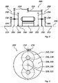
- 3 shows the drive device 200 in a side view.
- the motor shaft 204 has a first end associated with the first gear 206 and a second end associated with the second gear 208 .
- the gears 206, 208 each have the same translations and are constructed mirror-symmetrically to one another.
- Transmissions 206, 208 each have a first sun gear 220, 222 on the motor side, a second sun gear 224, 226 on the output side, and planetary gears, such as 232, which are effective between first sun gear 220, 222 and second sun gear 224, 226 and are arranged on a planet carrier 228, 230 , 234, 236, 238, on.
- the first sun gear 220 of the first transmission 206 is arranged at the first end of the motor shaft 204 and is non-rotatably connected thereto.
- the first sun gear 222 of the second transmission 208 is arranged at the second end of the motor shaft 204 and is connected to it in a rotationally fixed manner.
- the second sun gear 224 of the first transmission 206 is arranged on the first output shaft and is non-rotatably connected thereto.
- the second sun gear 226 of the second transmission 208 is arranged on the second output shaft and is non-rotatably connected thereto.
- the transmissions 206, 208 each have two first planet gears 232, 234 assigned to the first sun gear 220, 222 and two second planet gears 236, 238 assigned to the second sun gear 224, 226.
- a first planetary gear 232, 234 and a second planetary gear 236, 238 each form a pair of planetary gears which are non-rotatably connected to one another.
- the gears 206, 208 each have two pairs of planets.
- a first sun gear 220, 222 and a first planet gear 232, 234 each form a first translation.
- a second sun gear 224, 226 and a second planet gear 236, 238 each form a second translation.
- the planet carriers 228, 230 each have a toothing 240, 242 for coupling the gears 206, 208 to one another.
- the planetary carrier 228 of the first transmission 206 and the planetary carrier 230 of the second transmission 208 are coupled to one another by means of the coupling elements 214, 216 in order to support torque between the first output 210 and the second output 212 and to enable a speed difference.
- the first coupling element 214 is gear-connected to the planet carrier 228 of the first transmission 206 and to the second coupling element 216 .
- the first coupler 214 is shown exposed to show the interlocking between the couplers 214,216.
- the second coupling element 216 is connected to the first coupling element 214 and gear-connected to the planetary carrier 230 of the second transmission 208 .
- FIG 4 shows an integrated drive device 300, such as drive device 100 according to FIG 1 , with a drive motor 302 designed as an electric motor, two gears 304, 306 designed as spur planetary gears and a coupling that is formed using a coupling element 308 designed as a wide reverse wheel and a coupling element 310 designed as a long coupling shaft, in half section along a main axis 312.
- the coupling element 308 has a wide toothing, which is in engagement both with a toothing of the coupling element 310 and with a toothing of the planetary carrier 316 of the first gear 304 .
- the coupling element 310 extends between the gears 304, 306 and is gear-connected to the planet carrier 314 of the second gear 306. Incidentally, in addition, in particular 2 and 3 as well as the associated description.
- figure 5 shows an integrated drive device 400 with a drive motor 402 designed as an electric motor, two gears 404, 406 designed as spur planetary gears and a coupling, which is formed using a coupling element 408 designed as a short reverse wheel and a coupling element 410 designed as a long coupling shaft, in half section along a main axis 412.
- the coupling element 408 is gear-connected both to the planetary carrier 416 of the first gear 404 and to the coupling element 410 .
- the coupling element 410 extends between the gears 404, 406 and is gear-connected to the planet carrier 414 of the second gear 406. Incidentally, in addition, in particular 2 and 3 as well as the associated description.
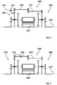
- FIG. 6 shows an integrated drive device 500 with a drive motor 502 designed as an electric motor, two gears 504, 506 designed as spur planetary gears, a coupling that is formed using two coupling elements 508, 510 designed as coupling shafts, a housing 512 and a Brake 514 in half section along a main axis 516.
- the brake 514 is used to brake the planetary carrier 518 of the first gear 504 against the housing 512 in order to reduce a speed difference between the first output shaft and the second output shaft and/or to block speed equalization.
- FIG. 7 shows an integrated drive device 600 with a drive motor 602 designed as an electric motor, two gearboxes 604, 606 designed as spur planetary gears, a coupling that is formed using two coupling elements 608, 610 designed as coupling shafts, and a shifting element 612 designed as a separating clutch, in half section along a Main axis 614.
- the switching element 612 is arranged on the coupling element 608 and can be switched between a closed switching position and an open switching position. The coupling between the first gear 604 and the second gear can thus be separated.
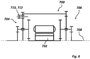
- FIG. 8 shows an integrated drive device 700 with a drive motor 702 designed as an electric motor, two gears 704, 706 designed as spur planetary gears, a coupling and an axially displaceable reverse wheel in half section along a main axis 708.
- the reverse wheel serves both as a coupling element 710 and as a switching element 712
- the rest is supplemented in particular Figure 2, Figure 3 and figure 5 as well as the associated description.
- isolated features can also be selected from the combinations of features disclosed here and with the resolution of a structural and/or functional one that may exist between the features context in combination with other features to delimit the subject-matter of the claim.
Abstract
Antriebsvorrichtung (100) für ein Kraftfahrzeug, die Antriebsvorrichtung (100) aufweisend einen Antriebsmotor (102), einen ersten Abtrieb (112), einen zweiten Abtrieb (114), ein leistungsverzweigendes erstes Getriebe (104,) mit einem dem Antriebsmotor (102) zugeordneten Getriebeeingang, einem dem ersten Abtrieb (112) zugeordneten Getriebeausgang und einer Koppelschnittstelle und ein leistungsverzweigendes zweites Getriebe (106) mit einem dem Antriebsmotor (102) zugeordneten Getriebeeingang, einem dem zweiten Abtrieb (114) zugeordneten Getriebeausgang und einer Koppelschnittstelle, wobei die Koppelschnittstelle des ersten Getriebes (104) und die Koppelschnittstelle des zweiten Getriebes (106) miteinander zum Drehzahlausgleich gekoppelt sind, und Kraftfahrzeug mit einer derartigen Antriebsvorrichtung (100).Drive device (100) for a motor vehicle, the drive device (100) having a drive motor (102), a first output (112), a second output (114), a power-split first transmission (104) with a drive motor (102) assigned Transmission input, a transmission output assigned to the first output (112) and a coupling interface, and a power-split second transmission (106) with a transmission input assigned to the drive motor (102), a transmission output assigned to the second output (114) and a coupling interface, the coupling interface of the first Gear (104) and the coupling interface of the second gear (106) are coupled to each other for speed compensation, and motor vehicle with such a drive device (100).
Description
Die Erfindung betrifft eine Antriebsvorrichtung für ein Kraftfahrzeug, die Antriebsvorrichtung aufweisend einen Antriebsmotor, einen ersten Abtrieb, einen zweiten Abtrieb, ein mit dem Antriebsmotor gekoppeltes und dem ersten Abtrieb zugeordnetes leistungsverzweigendes erstes Getriebe und ein mit dem Antriebsmotor gekoppeltes und dem zweiten Abtrieb zugeordnetes leistungsverzweigendes zweites Getriebe. Außerdem betrifft die Erfindung ein Kraftfahrzeug.The invention relates to a drive device for a motor vehicle, the drive device having a drive motor, a first output, a second output, a power-split first transmission coupled to the drive motor and assigned to the first output, and a power-split second transmission coupled to the drive motor and assigned to the second output . The invention also relates to a motor vehicle.
Das Dokument
Das Dokument
Das Dokument
Das Dokument
Der Erfindung liegt die Aufgabe zugrunde, eine eingangs genannte Antriebsvorrichtung strukturell und/oder funktionell zu verbessern. Außerdem liegt der Erfindung die Aufgabe zugrunde, ein eingangs genanntes Kraftfahrzeug strukturell und/oder funktionell zu verbessern.The object of the invention is to structurally and/or functionally improve a drive device as mentioned at the outset. In addition, the invention is based on the object of improving the structure and/or functionality of a motor vehicle as mentioned at the outset.
Die Aufgabe wird gelöst mit einer Antriebsvorrichtung mit den Merkmalen des Anspruchs 1. Außerdem wird die Aufgabe gelöst mit einem Kraftfahrzeug mit den Merkmalen des Anspruchs 10. Vorteilhafte Ausführungen und/oder Weiterbildungen sind Gegenstand der abhängigen Ansprüche.The object is achieved with a drive device having the features of claim 1. The object is also achieved with a motor vehicle having the features of claim 10. Advantageous embodiments and/or developments are the subject matter of the dependent claims.
Die Antriebsvorrichtung kann zur Anordnung in einem Antriebsstrang dienen. Die Antriebsvorrichtung kann einen Antrieb und zwei Abtriebe aufweisen. Die Antriebsvorrichtung kann als Differentialgetriebe, Ausgleichsgetriebe, Verteilergetriebe und/oder Achsgetriebe dienen. Die Antriebsvorrichtung kann ein Gehäuse aufweisen. Der Antriebsmotor, das leistungsverzweigende erste Getriebe und das leistungsverzweigende zweite Getriebe können gemeinsam in dem Gehäuse angeordnet sein. Der Antriebsmotor, das erste Getriebe und das zweite Getriebe können zusätzlich strukturell und/oder funktionell miteinander verbunden sein. Insofern kann die Antriebsvorrichtung auch als integrierte Antriebsvorrichtung bezeichnet werden. Der erste Abtrieb kann mithilfe einer ersten Ausgangswelle gebildet sein. Der zweite Abtrieb kann mithilfe einer zweiten Ausgangswelle gebildet sein. Die erste Ausgangswelle und die zweite Ausgangswelle können/kann, insbesondere an dem Gehäuse, drehbar gelagert sein. Das erste Getriebe kann zwischen dem Getriebeeingang und dem Getriebeausgang einen ersten Leistungszweig und zwischen dem Getriebeeingang und dem Getriebeausgang einerseits und der Koppelschnittstelle andererseits einen zweiten Leistungszweig aufweisen. Das erste Getriebe kann zwischen dem Antriebsmotor und den ersten Abtrieb, zwischen dem Antriebsmotor und der Koppelung und/oder zwischen dem Abtrieb und der Koppelung wirksam sein. Das zweite Getriebe kann zwischen dem Getriebeeingang und dem Getriebeausgang einen ersten Leistungszweig und zwischen dem Getriebeeingang und dem Getriebeausgang einerseits und der Koppelschnittstelle andererseits einen zweiten Leistungszweig aufweisen. Das zweite Getriebe kann zwischen dem Antriebsmotor und dem zweiten Abtrieb, zwischen dem Antriebsmotor und der Koppelung und/oder zwischen dem Abtrieb und der Koppelung wirksam sein.The drive device can be used for arrangement in a drive train. The drive device can have an input and two outputs. The drive device can serve as a differential gear, differential gear, transfer case and/or axle drive. The drive device can have a housing. The drive motor, the power-split first transmission and the power-split second transmission can be arranged together in the housing. The drive motor, the first transmission and the second transmission can additionally be structurally and/or functionally connected to one another. In this respect, the drive device can also be referred to as an integrated drive device. The first output can be formed using a first output shaft. The second output can be formed using a second output shaft. The first output shaft and the second output shaft can/can be rotatably mounted, in particular on the housing. The first transmission can have a first power branch between the transmission input and the transmission output and a second power branch between the transmission input and the transmission output on the one hand and the coupling interface on the other hand. The first gear can be effective between the drive motor and the first output, between the drive motor and the coupling and/or between the output and the coupling. The second transmission can have a first power branch and between the transmission input and the transmission output between the transmission input and the transmission output on the one hand and the coupling interface on the other hand have a second power branch. The second gear can be effective between the drive motor and the second output, between the drive motor and the coupling and/or between the output and the coupling.
Soweit nicht anders angegeben oder es sich aus dem Zusammenhang nicht anders ergibt, beziehen sich die Angaben "axial", "radial" und "in Umfangsrichtung" auf eine Erstreckungsrichtung der Hauptachse der Antriebsvorrichtung. "Axial" entspricht dann einer Erstreckungsrichtung der Hauptachse der Antriebsvorrichtung. "Radial" ist dann eine zur Erstreckungsrichtung der Hauptachse der Antriebsvorrichtung senkrechte und sich mit der Hauptachse der Antriebsvorrichtung schneidende Richtung. "In Umfangsrichtung" entspricht dann einer Kreisbogenrichtung um die Hauptachse der Antriebsvorrichtung.Unless otherwise stated or if the context does not indicate otherwise, the terms "axial", "radial" and "in the circumferential direction" refer to a direction of extension of the main axis of the drive device. “Axial” then corresponds to a direction of extension of the main axis of the drive device. “Radial” is then a direction that is perpendicular to the direction in which the main axis of the drive device extends and intersects with the main axis of the drive device. "In the circumferential direction" then corresponds to a circular arc direction around the main axis of the drive device.
Der Antriebsmotor kann als Fahrantriebsmotor dienen. Der Antriebsmotor kann als primärer oder sekundärer Antriebsmotor dienen. Der Antriebsmotor kann eine elektrische Antriebsmaschine sein. Die elektrische Antriebsmaschine kann als Motor und/oder als Generator betreibbar sein. Der Antriebsmotor kann zwischen dem ersten Getriebe und dem zweiten Getriebe angeordnet sein. Der Antriebsmotor kann einen Stator und einen Rotor aufweisen. Der Stator kann gehäusefest sein. Der Antriebsmotor kann eine Motorwelle aufweisen. Die Motorwelle kann mit dem Rotor drehfest verbunden sein. Der Rotor und/oder die Motorwelle können/kann, insbesondere an dem Gehäuse, drehbar gelagert sein. Die Motorwelle kann ein erstes Ende, das dem ersten Getriebe zugeordnet ist, und ein zweites Ende, das dem zweiten Getriebe zugeordnet ist, aufweisen.The drive motor can serve as a traction drive motor. The drive motor can serve as a primary or secondary drive motor. The drive motor can be an electric drive machine. The electric drive machine can be operated as a motor and/or as a generator. The drive motor can be arranged between the first gear and the second gear. The drive motor can have a stator and a rotor. The stator can be fixed to the housing. The drive motor can have a motor shaft. The motor shaft can be non-rotatably connected to the rotor. The rotor and/or the motor shaft can/can be rotatably mounted, in particular on the housing. The motor shaft may have a first end associated with the first gear and a second end associated with the second gear.
Der Antriebsmotor kann eine Motordrehachse aufweisen. Das erste Getriebe und das zweite Getriebe können jeweils eine Getriebehauptachse aufweisen. Die Motordrehachse und die Getriebehauptachsen können zueinander koaxial angeordnet sein. Die Motordrehachse und die Getriebehauptachsen können eine Hauptachse der Antriebsvorrichtung bilden. Der Antriebsmotor kann zentral angeordnet sein. Das erste Getriebe und das zweite Getriebe können zum Antriebsmotor spiegelsymmetrisch angeordnet sein. Der Antriebsmotor kann mittig angeordnet sein. Das erste Getriebe und das zweite Getriebe können beidseits des Antriebsmotors angeordnet sein.The drive motor can have a motor axis of rotation. The first gear and the second gear can each have a main gear axis. The axis of rotation of the engine and the main axes of the transmission can be arranged coaxially with one another. The axis of rotation of the engine and the main axes of the transmission can form a main axis of the drive device. The drive motor can be arranged centrally. The first gear and the second gear can be arranged mirror-symmetrically to the drive motor. The drive motor can be arranged in the middle be. The first gear and the second gear can be arranged on both sides of the drive motor.
Das leistungsverzweigende erste Getriebe und das leistungsverzweigende zweite Getriebe können gleiche Übersetzungen aufweisen. Das erste Getriebe und das zweite Getriebe können jeweils rotationssymmetrisch aufgebaut sein. Das erste Getriebe und das zweite Getriebe können zueinander spiegelsymmetrisch aufgebaut sein. Das erste Getriebe und das zweite Getriebe können jeweils als Planetengetriebe ausgeführt sein. Das erste Getriebe und das zweite Getriebe können jeweils ein motorseitiges erstes Sonnenrad, ein ausgangsseitiges zweites Sonnenrad und zwischen dem ersten Sonnenrad und dem zweiten Sonnenrad wirksame, an einem Planetenträger angeordnete Planetenräder aufweisen. Die ersten Sonnenräder können jeweils einen Getriebeeingang bilden. Die zweiten Sonnenräder können jeweils einen Getriebeausgang bilden. Die ersten Planetenträger können jeweils eine Koppelschnittstelle bilden. Das erste Sonnenrad des ersten Getriebes kann an dem ersten Ende der Motorwelle angeordnet sein. Das erste Sonnenrad des zweiten Getriebes kann an dem zweiten Ende der Motorwelle angeordnet sein. Die ersten Sonnenräder können jeweils mit der Motorwelle drehfest verbunden sein. Das zweite Sonnenrad des ersten Getriebes kann an der ersten Ausgangswelle angeordnet sein. Das zweite Sonnenrad des ersten Getriebes kann mit der ersten Ausgangswelle drehfest verbunden sein. Das zweite Sonnenrad des zweiten Getriebes kann an der zweiten Ausgangswelle angeordnet sein. Das zweite Sonnenrad des zweiten Getriebes kann mit der zweiten Ausgangswelle drehfest verbunden sein. Die Getriebe können jeweils wenigstens ein dem ersten Sonnenrad zugeordnetes erstes Planetenrad und wenigstens ein dem zweiten Sonnenrad zugeordnetes zweites Planetenrad aufweisen. Das wenigstens eine erste Planetenrad und das erste Sonnenrad können in einer gemeinsamen Ebene angeordnet sein. Das wenigstens eine zweite Planetenrad und das zweite Sonnenrad können in einer gemeinsamen Ebene angeordnet sein. Das wenigstens eine erste Planetenrad und das wenigstens eine zweite Planetenrad können ein miteinander drehfest verbundenes Planetenradpaar bilden. Ein Planetenradpaar kann an einem Planetenträger gemeinsam drehbar gelagert sein. Das erste Getriebe und das zweite Getriebe können jeweils wenigstens ein Planetenpaar, insbesondere zwei oder drei Planetenpaare, aufweisen. Die Planetenpaare können bezüglich der Hauptachsen der Getriebe in Umfangsrichtung, insbesondere gleichmäßig, verteilt angeordnet sein. Ein erstes Sonnenrad und ein erstes Planetenrad können jeweils eine erste Übersetzungsstufe aufweisen. Ein zweites Sonnenrad und ein zweites Planetenrad können jeweils eine zweite Übersetzungsstufe aufweisen. Die Planetenträger können jeweils eine Verzahnung aufweisen. Die Verzahnungen der Planetenträger können zum Koppeln der Getriebe miteinander dienen. Der Planetenträger eines Getriebes kann axial zwischen dem ersten Sonnenrad und dem zweiten Sonnenrad dieses Getriebes angeordnet sein. Der Planetenträger eines Getriebes kann ringartig oder scheibenartig ausgeführt sein. Der Planetenträger eines Getriebes kann axial außenseitig des wenigstens einen ersten Planetenrads und axial außenseitig des wenigstens einen zweiten Planetenrads dieses Getriebes angeordnet sein und das wenigstens eine erste Planetenrad und das wenigstens eine zweite Planetenenrad radial außenseitig umgreifen. Der Planetenträger eines Getriebes kann axial zwischen dem ersten Sonnenrad und dem zweiten Sonnenrad und axial außenseitig des wenigstens einen ersten Planetenrads dieses Getriebes angeordnet sein und das wenigsten eine erste Planetenrad radial außenseitig umgreifen. Der Planetenträger eines Getriebes kann axial zwischen dem ersten Sonnenrad und dem zweiten Sonnenrad und axial außenseitig des wenigstens einen zweiten Planetenrads dieses Getriebes angeordnet sein und das wenigstens eine zweite Planetenrad radial außenseitig umgreifen. Der Planetenträger eines Getriebes kann käfigartig oder hohlzylinderartig ausgeführt sein. Die Planetenträger können jeweils an der Motorwelle, an einer Ausgangswelle und/oder an dem Gehäuse drehbar gelagert sein.The power-split first transmission and the power-split second transmission can have the same gear ratios. The first gear and the second gear can each be constructed in a rotationally symmetrical manner. The first gear and the second gear can be constructed mirror-symmetrical to one another. The first gear and the second gear can each be designed as a planetary gear. The first transmission and the second transmission can each have a motor-side first sun wheel, an output-side second sun wheel and planetary wheels acting between the first sun wheel and the second sun wheel and arranged on a planetary carrier. The first sun gears can each form a transmission input. The second sun gears can each form a transmission output. The first planet carriers can each form a coupling interface. The first sun gear of the first transmission can be arranged at the first end of the motor shaft. The first sun gear of the second gear can be arranged at the second end of the motor shaft. The first sun gears can each be connected to the motor shaft in a torque-proof manner. The second sun gear of the first transmission can be arranged on the first output shaft. The second sun gear of the first transmission can be connected to the first output shaft in a torque-proof manner. The second sun gear of the second transmission can be arranged on the second output shaft. The second sun gear of the second transmission can be connected in a rotationally fixed manner to the second output shaft. The transmissions can each have at least one first planet gear assigned to the first sun gear and at least one second planet gear assigned to the second sun gear. The at least one first planet wheel and the first sun wheel can be arranged in a common plane. The at least one second planet wheel and the second sun wheel can be arranged in a common plane. The at least one first planetary gear and the at least one second planetary gear can form a pair of planetary gears that are non-rotatably connected to one another. A pair of planet gears can be rotatably mounted together on a planet carrier. The first gear and the second gear can each have at least one pair of planets, in particular two or three Pairs of planets have. The pairs of planets can be distributed, in particular evenly, in the circumferential direction with respect to the main axes of the transmission. A first sun gear and a first planetary gear can each have a first gear ratio. A second sun gear and a second planetary gear can each have a second gear ratio. The planet carriers can each have a toothing. The teeth of the planet carrier can be used to couple the gears together. The planet carrier of a transmission can be arranged axially between the first sun gear and the second sun gear of this transmission. The planet carrier of a transmission can be ring-like or disc-like. The planet carrier of a transmission can be arranged axially on the outside of the at least one first planet wheel and axially on the outside of the at least one second planet wheel of this transmission and can encompass the at least one first planet wheel and the at least one second planet wheel radially on the outside. The planet carrier of a transmission can be arranged axially between the first sun gear and the second sun gear and axially outside of the at least one first planet gear of this transmission and can encompass the at least one first planet gear radially outside. The planet carrier of a transmission can be arranged axially between the first sun gear and the second sun gear and axially outside the at least one second planet gear of this transmission and can encompass the at least one second planet gear radially outside. The planet carrier of a transmission can be designed like a cage or like a hollow cylinder. The planet carriers can each be rotatably mounted on the motor shaft, on an output shaft and/or on the housing.
Das erste Getriebe, insbesondere die Koppelschnittstelle des ersten Getriebes, und das zweite Getriebe, insbesondere die Koppelschnittstelle des zweiten Getriebes, können miteinander gekoppelt sein, um eine Drehzahldifferenz zwischen der ersten Ausgangswelle und der zweiten Ausgangswelle zu ermöglichen. Das erste Getriebe, insbesondere die Koppelschnittstelle des ersten Getriebes, und das zweite Getriebe, insbesondere die Koppelschnittstelle des zweiten Getriebes, können miteinander ohne betragsmäßige Übersetzungsänderung gekoppelt sein. Das erste Getriebe, insbesondere die Koppelschnittstelle des ersten Getriebes, und das zweite Getriebe, insbesondere die Koppelschnittstelle des zweiten Getriebes, können miteinander drehrichtungsumkehrend gekoppelt sein. Das erste Getriebe, insbesondere die Koppelschnittstelle des ersten Getriebes, und das zweite Getriebe, die Koppelschnittstelle des zweiten Getriebes, können miteinander mit einer Übersetzung i=-1 gekoppelt sein.The first gear, in particular the coupling interface of the first gear, and the second gear, in particular the coupling interface of the second gear, can be coupled to one another in order to enable a rotational speed difference between the first output shaft and the second output shaft. The first transmission, in particular the coupling interface of the first transmission, and the second transmission, in particular the coupling interface of the second transmission, can be coupled to one another without a change in transmission ratio. The first gear, in particular the coupling interface of the first gear, and the second gear, in particular the coupling interface of the second gear can be coupled to one another in a reversing direction of rotation. The first gear, in particular the coupling interface of the first gear, and the second gear, the coupling interface of the second gear, can be coupled to one another with a gear ratio i=−1.
Die Koppelschnittstelle des ersten Getriebes und die Koppelschnittstelle des zweiten Getriebes können miteinander mithilfe wenigstens eines Koppelelements gekoppelt sein. Das wenigstens eine Koppelelement kann, insbesondere an dem Gehäuse, drehbar gelagert sein. Die Koppelschnittstelle des ersten Getriebes und die Koppelschnittstelle des zweiten Getriebes können miteinander mithilfe mehrerer Koppelelemente gekoppelt sein. Die Koppelelemente können zusammenwirkend gruppiert sein. Die Koppelelementgruppen können bezüglich der Hauptachsen der Getriebe in Umfangsrichtung, insbesondere gleichmäßig, verteilt angeordnet sein. die Koppelschnittstelle des ersten Getriebes und die Koppelschnittstelle des zweiten Getriebes können miteinander mithilfe eines ersten Koppelelements und eines zweiten Koppelelements gekoppelt sein. Das erste Koppelelement kann zwischen dem ersten Getriebe und dem zweiten Koppelelement wirksam sein. Das zweite Koppelelement kann zwischen dem ersten Koppelelement und dem zweiten Getriebe wirksam sein. Das wenigstens eine Koppelelement, insbesondere das erste Koppelelement und/oder das zweite Koppelelement, können/kann als Koppelwelle, Zahnrad, Stirnrad, Hohlrad, Kettenrad oder Kette ausgeführt sein. Ein Koppelelement kann zur Drehrichtungsumkehr dienen. Ein zur Drehrichtungsumkehr dienendes Koppelelement kann als Zahnrad ausgeführt sein und/oder als Rücklaufrad bezeichnet werden. Eine Koppelwelle kann eine Welle mit Koppelverzahnungen sein. Das erste Koppelelement und das zweite Koppelelement können als Koppelwellen mit gleichen oder unterschiedlichen Längen ausgeführt sein. Das erste Koppelelement und das zweite Koppelelement können als Koppelwellen mit gleichen oder unterschiedlichen Koppelverzahnungsbreiten ausgeführt sein. Das erste Koppelelement kann als Zahnrad und das zweite Koppelelement kann als Koppelwelle ausgeführt sein. Das Koppelelement kann als zu den Hauptachsen der Getriebe parallele oder zu den Hauptachsen der Getriebe schräge Koppelwelle ausgeführt sein. Das erste Koppelelement kann als Kette und das zweite Koppelelement kann als Koppelwelle mit Kettenrad ausgeführt sein.The coupling interface of the first gear and the coupling interface of the second gear can be coupled to one another using at least one coupling element. The at least one coupling element can be rotatably mounted, in particular on the housing. The coupling interface of the first gear and the coupling interface of the second gear can be coupled to one another using a plurality of coupling elements. The coupling elements can be grouped cooperatively. The coupling element groups can be distributed, in particular evenly, in the circumferential direction with respect to the main axes of the transmission. the coupling interface of the first gear and the coupling interface of the second gear can be coupled to each other using a first coupling element and a second coupling element. The first coupling element can be effective between the first gear and the second coupling element. The second coupling element can be effective between the first coupling element and the second gear. The at least one coupling element, in particular the first coupling element and/or the second coupling element, can/can be designed as a coupling shaft, gear wheel, spur gear, ring gear, chain wheel or chain. A coupling element can be used to reverse the direction of rotation. A coupling element serving to reverse the direction of rotation can be designed as a gear wheel and/or referred to as a return wheel. A coupling shaft can be a shaft with coupling teeth. The first coupling element and the second coupling element can be designed as coupling shafts with the same or different lengths. The first coupling element and the second coupling element can be designed as coupling shafts with the same or different coupling toothing widths. The first coupling element can be designed as a gear and the second coupling element can be designed as a coupling shaft. The coupling element can take the form of a coupling shaft which is parallel to the main axes of the transmission or oblique to the main axes of the transmission be executed. The first coupling element can be designed as a chain and the second coupling element can be designed as a coupling shaft with a chain wheel.
Das erste Getriebe, das zweite Getriebe und/oder wenigstens ein Koppelelement können/kann eine Bremse aufweisen. Die Bremse kann strukturell und/oder funktionell integriert sein. Die Bremse kann auf einen Drehfreiheitsgrad der Koppelung zwischen den Getrieben wirken. Die Bremse kann zum Reduzieren der Drehzahl der Koppelung und damit einer Drehzahldifferenz zwischen der ersten Ausgangswelle und der zweiten Ausgangswelle dienen. Die Bremse kann zum Sperren eines Drehzahlausgleichs dienen. Die Bremse kann als Differentialsperre dienen. Die Bremse kann zum Bremsen eines Planetenträgers und/oder eines Koppelelements dienen. Die Bremse kann manuell und/oder automatisiert kontrollierbar sein. Die Bremse kann regelungstechnisch und/oder steuerungstechnisch kontrollierbar sein. Die Bremse kann unter Berücksichtigung wenigstens einer Eingangsgröße, wie Drehzahl oder Drehzahldifferenz, kontrollierbar sein. Die Bremse kann kraftschlüssig, insbesondere reibschlüssig, oder formschlüssig wirksam sein. Die Bremse kann mithilfe fliehkraftabhängig oder differenzdrehzahlabhängig kontrollierbar sein. Die Bremse kann als Fliehkraftkupplung oder mit dem Wirkprinzip einer Visco-Kupplung ausgeführt sein.The first gear, the second gear and/or at least one coupling element can/can have a brake. The brake can be structurally and/or functionally integrated. The brake can act on a rotational degree of freedom of the coupling between the gears. The brake can serve to reduce the speed of the coupling and thus a speed difference between the first output shaft and the second output shaft. The brake can be used to lock a speed compensation. The brake can serve as a differential lock. The brake can be used to brake a planet carrier and/or a coupling element. The brake can be controlled manually and/or automatically. The brake can be controllable in terms of regulation and/or control technology. The brake can be controllable, taking into account at least one input variable, such as speed or speed difference. The brake can be non-positive, in particular frictional, or form-fitting. The brake can be controlled as a function of centrifugal force or speed difference. The brake can be designed as a centrifugal clutch or with the operating principle of a visco clutch.
Die Koppelung zwischen dem ersten Getriebe und dem zweiten Getriebe kann, beispielsweise zur Entkoppelung der Antriebsmaschine von den Antriebsrädern, trennbar sein. Die Koppelung zwischen dem ersten Getriebe und dem zweiten Getriebe kann ein Schaltelement aufweisen. Das Schaltelement kann zwischen einer geschlossenen Schaltstellung und einer geöffneten Schaltstellung schaltbar sein. Das Schaltelement kann manuell und/oder automatisiert kontrollierbar sein. Das Schaltelement kann regelungstechnisch und/oder steuerungstechnisch kontrollierbar sein. Das Schaltelement kann unter Berücksichtigung wenigstens einer Eingangsgröße kontrollierbar sein. Das Schaltelement kann kraftschlüssig, insbesondere reibschlüssig, oder formschlüssig wirksam sein. Das Schaltelement kann als Reibungskupplung oder als Klauenkupplung ausgeführt sein. Das Schaltelement kann als axiale verschiebbares Zahnrad ausgeführt sein. Die Bremse und das Schaltelement können strukturell und/oder funktionell miteinander verbunden sein.The coupling between the first gear and the second gear can be separable, for example for decoupling the engine from the drive wheels. The coupling between the first gear and the second gear can have a switching element. The switching element can be switched between a closed switching position and an open switching position. The switching element can be controlled manually and/or automatically. The switching element can be controlled by regulation and/or control technology. The switching element can be controllable taking into account at least one input variable. The switching element can be non-positively, in particular frictionally, or positively effective. The switching element can be designed as a friction clutch or as a claw clutch. The switching element can be designed as an axially displaceable gear wheel. The brake and the switching element can be structurally and/or functionally connected to one another.
Das Kraftfahrzeug kann ein Hybridelektrokraftfahrzeug oder ein Elektrokraftfahrzeug sein. Das Kraftfahrzeug kann einen von dem Antriebsmotor der Antriebsvorrichtung gesonderten Antriebsmotor aufweisen. Der Antriebsmotor des Kraftfahrzeugs kann eine Brennkraftmaschine oder eine elektrische Maschine sein. Der Antrieb der Antriebsvorrichtung kann mithilfe des Antriebsmotors des Kraftfahrzeugs antreibbar sein. Wenn das Kraftfahrzeug einen gesonderten Antriebsmotor aufweist, kann der Antriebsmotor der Antriebsvorrichtung als sekundärer Antriebsmotor dienen. Das Kraftfahrzeug kann einen Antriebsstrang aufweisen. Die Antriebsvorrichtung kann in dem Antriebsstrang angeordnet sein. Der Antriebsstrang kann durch die Antriebsvorrichtung gebildet werden. Die Antriebsvorrichtung kann als Achsgetriebe dienen. Das Kraftfahrzeug kann wenigstens ein erstes antreibbares Fahrzeugrad und wenigstens ein zweites antreibbares Fahrzeugrad aufweisen. Das erste Fahrzeugrad kann mithilfe der ersten Ausgangswelle antreibbar sein. Das zweite Fahrzeugrad kann mithilfe der zweiten Ausgangswelle antreibbar sein.The motor vehicle may be a hybrid electric vehicle or an electric vehicle. The motor vehicle can have a drive motor that is separate from the drive motor of the drive device. The drive motor of the motor vehicle can be an internal combustion engine or an electric machine. The drive of the drive device can be driven using the drive motor of the motor vehicle. If the motor vehicle has a separate drive motor, the drive motor of the drive device can serve as a secondary drive motor. The motor vehicle can have a drive train. The drive device can be arranged in the drive train. The drive train can be formed by the drive device. The drive device can serve as an axle drive. The motor vehicle can have at least one first drivable vehicle wheel and at least one second drivable vehicle wheel. The first vehicle wheel can be drivable using the first output shaft. The second vehicle wheel can be driven using the second output shaft.
Zusammenfassend und mit anderen Worten dargestellt ergibt sich somit durch die Erfindung unter anderem eine Integrierte Antriebsachse. Die Integrierte Antriebsachse kann einen Antriebsmotor, insbesondere eine elektrische Maschine, aufweisen, deren Rotor auf beiden Seiten je ein Planetengetriebe antreibt, wobei diese als reine Stirnradplanetengetriebe ausgeführt sein können. Die beiden Planetenträger rechts und links des Antriebsmotors können durch eine mechanische Koppelung, beispielsweise durch Verzahnungen und Wellen realisiert, miteinander wirkverbunden sein, sodass ihre Drehbewegungen unterschiedliche Richtungen aufweisen. Planetenträger können jeweils eine ganzzahlige Anzahl von Zahnradpaaren tragen, die durch eine Achse verbunden sind, welche im Planetenträger drehbar gelagert ist. Die zur Seite des Antriebsmotors hin angeordneten Planeten können mit den Sonnenrädern des Rotors bzw. der Rotor- oder Eingangswelle der Antriebseinheit kämmen. Die anderen Planeten können mit den Sonnenrädern auf den beiderseitigen Abtriebswellen kämmen, die über die Seitenwellen mit den Antriebsrädern verbunden sind.In summary and presented in other words, the invention thus results, among other things, in an integrated drive axle. The integrated drive axle can have a drive motor, in particular an electric machine, the rotor of which drives a planetary gear on both sides, which can be designed as a pure spur planetary gear. The two planetary carriers on the right and left of the drive motor can be operatively connected to one another by a mechanical coupling, realized for example by gearing and shafts, so that their rotary movements have different directions. Planetary carriers can each carry an integral number of pairs of gears connected by an axle which is journalled in the planetary carrier for rotation. The planets arranged on the side of the drive motor can mesh with the sun gears of the rotor or the rotor or input shaft of the drive unit. The other planets can mesh with the sun gears on the output shafts on both sides, which are connected to the drive wheels via the side shafts.
Mit der Erfindung wird ein Bauraumbedarf reduziert. Ein Drehzahlausgleich wird ermöglich. Ein Aufwand, wie Herstellungsaufwand, wird reduziert. Lokale Belastungen können reduziert werden. Eine Differentialsperre kann bereitgestellt werden. Ein Wirkungsgrad kann erhöht werden. Ein Komfort, beispielsweise ein Akustikverhalten, kann verbessert werden.With the invention, a space requirement is reduced. Speed equalization is made possible. An expense, such as manufacturing expense, is reduced. Local loads can be reduced. A differential lock can be provided. An efficiency can be increased. Comfort, for example acoustic behavior, can be improved.
Nachfolgend werden Ausführungsbeispiele der Erfindung unter Bezugnahme auf Figuren näher beschrieben, dabei zeigen schematisch und beispielhaft:
- Fig. 1
- eine integrierte Antriebsvorrichtung mit einem Antriebsmotor, zwei leistungsverzweigenden Getrieben und einer Koppelung,
- Fig. 2
- eine integrierte Antriebsvorrichtung mit einem als Elektromotor ausgeführten Antriebsmotor, zwei als Planetengetriebe ausgeführten Getrieben und einer mithilfe von zwei Koppelwellen gebildeten Koppelung im Halbschnitt entlang einer Hauptachse,
- Fig. 3
- eine integrierte Antriebsvorrichtung mit einem als Elektromotor ausgeführten Antriebsmotor, zwei als Planetengetriebe ausgeführten Getrieben und einer mithilfe von zwei Koppelwellen gebildeten Koppelung in seitlicher Ansicht,
- Fig. 4
- eine integrierte Antriebsvorrichtung mit einem als Elektromotor ausgeführten Antriebsmotor, zwei als Planetengetriebe ausgeführten Getrieben und einer mithilfe einer langen Koppelwelle und einem breiten Rücklaufrad gebildeten Koppelung im Halbschnitt entlang einer Hauptachse,
- Fig. 5
- eine integrierte Antriebsvorrichtung mit einem als Elektromotor ausgeführten Antriebsmotor, zwei als Planetengetriebe ausgeführten Getrieben und einer mithilfe einer langen Koppelwelle und einem kurzen Rücklaufrad gebildeten Koppelung im Halbschnitt entlang einer Hauptachse,
- Fig. 6
- eine integrierte Antriebsvorrichtung mit einem als Elektromotor ausgeführten Antriebsmotor, zwei als Planetengetriebe ausgeführten Getrieben, einer mithilfe von zwei Koppelwellen gebildeten Koppelung und einer Bremse im Halbschnitt entlang einer Hauptachse,
- Fig. 7
- eine integrierte Antriebsvorrichtung mit einem als Elektromotor ausgeführten Antriebsmotor, zwei als Planetengetriebe ausgeführten Getrieben, einer mithilfe von zwei Koppelwellen gebildeten Koppelung und einem Schaltelement im Halbschnitt entlang einer Hauptachse und
- Fig. 8
- eine integrierte Antriebsvorrichtung mit einem als Elektromotor ausgeführten Antriebsmotor, zwei als Planetengetriebe ausgeführten Getrieben, einer Koppelung und einem verschiebbaren Rücklaufrad als Koppelelement und Schaltelement im Halbschnitt entlang einer Hauptachse.
- 1
- an integrated drive device with a drive motor, two power-split transmissions and a coupling,
- 2
- an integrated drive device with a drive motor designed as an electric motor, two gears designed as planetary gears and a coupling formed by means of two coupling shafts in half section along a main axis,
- 3
- an integrated drive device with a drive motor designed as an electric motor, two gears designed as planetary gears and a coupling formed by means of two coupling shafts in a side view,
- 4
- an integrated drive device with a drive motor designed as an electric motor, two gears designed as planetary gears and a coupling formed by means of a long coupling shaft and a wide reverse wheel in half section along a main axis,
- figure 5
- an integrated drive device with a drive motor designed as an electric motor, two gears designed as planetary gears and a coupling formed by means of a long coupling shaft and a short reverse wheel in half section along a main axis,
- 6
- an integrated drive device with a drive motor designed as an electric motor, two gears designed as planetary gears, a coupling formed by means of two coupling shafts and a brake in half section along a main axis,
- 7
- an integrated drive device with a drive motor designed as an electric motor, two gears designed as planetary gears, a coupling formed by means of two coupling shafts and a switching element in half section along a main axis and
- 8
- an integrated drive device with a drive motor designed as an electric motor, two gears designed as planetary gears, a coupling and a displaceable reverse wheel as a coupling element and switching element in half section along a main axis.
Die Motorwelle 204 weist ein erstes Ende, das dem ersten Getriebe 206 zugeordnet ist, und ein zweites Ende, das dem zweiten Getriebe 208 zugeordnet ist, auf. Die Getriebe 206, 208 weisen jeweils gleiche Übersetzungen auf und sind zueinander spiegelsymmetrisch aufgebaut. Die Getriebe 206, 208 weisen jeweils ein motorseitiges erstes Sonnenrad 220, 222, ein ausgangsseitiges zweites Sonnenrad 224, 226 und zwischen dem ersten Sonnenrad 220, 222 und dem zweiten Sonnenrad 224, 226 wirksame, an einem Planetenträger 228, 230 angeordnete Planetenräder, wie 232, 234, 236, 238, auf. Das erste Sonnenrad 220 des ersten Getriebes 206 ist an dem ersten Ende der Motorwelle 204 angeordnet und mit dieser drehfest verbunden. Das erste Sonnenrad 222 des zweiten Getriebes 208 ist an dem zweiten Ende der Motorwelle 204 angeordnet und mit dieser drehfest verbunden. Das zweite Sonnenrad 224 des ersten Getriebes 206 ist an der ersten Ausgangswelle angeordnet und mit dieser drehfest verbunden. Das zweite Sonnenrad 226 des zweiten Getriebes 208 ist an der zweiten Ausgangswelle angeordnet und mit dieser drehfest verbunden. Die Getriebe 206, 208 weisen jeweils zwei dem ersten Sonnenrad 220, 222 zugeordnete erste Planetenräder 232, 234 und zwei dem zweiten Sonnenrad 224, 226 zugeordnete zweite Planetenräder 236, 238 auf. Ein erstes Planetenrad 232, 234 und ein zweites Planetenrad 236, 238 bilden jeweils ein miteinander drehfest verbundenes Planetenradpaar. Die Getriebe 206, 208 weisen jeweils zwei Planetenpaare auf. Ein erstes Sonnenrad 220, 222 und ein erstes Planetenrad 232, 234 bilden jeweils eine erste Übersetzung. Ein zweites Sonnenrad 224, 226 und ein zweites Planetenrad 236, 238 bilden jeweils eine zweite Übersetzung. Die Planetenträger 228, 230 weisen jeweils eine Verzahnung 240, 242 zum Koppeln der Getriebe 206, 208 miteinander auf.The
Der Planetenträger 228 des ersten Getriebes 206 und der Planetenträger 230 des zweiten Getriebes 208 sind mithilfe der Koppelelemente 214, 216 miteinander gekoppelt, um zwischen dem ersten Abtrieb 210 und dem zweiten Abtrieb 212 Drehmoment abzustützen sowie eine Drehzahldifferenz zu ermöglichen. Das erste Koppelelement 214 ist mit dem Planetenträger 228 des ersten Getriebes 206 und mit dem zweiten Koppelelement 216 zahnradverbunden. In
Mit "kann" sind insbesondere optionale Merkmale der Erfindung bezeichnet. Demzufolge gibt es auch Weiterbildungen und/oder Ausführungsbeispiele der Erfindung, die zusätzlich oder alternativ das jeweilige Merkmal oder die jeweiligen Merkmale aufweisen.In particular, “may” denotes optional features of the invention. Accordingly, there are also developments and/or exemplary embodiments of the invention which additionally or alternatively have the respective feature or features.
Aus den vorliegend offenbarten Merkmalskombinationen können bedarfsweise auch isolierte Merkmale herausgegriffen und unter Auflösung eines zwischen den Merkmalen gegebenenfalls bestehenden strukturellen und/oder funktionellen Zusammenhangs in Kombination mit anderen Merkmalen zur Abgrenzung des Anspruchsgegenstands verwendet werden.If necessary, isolated features can also be selected from the combinations of features disclosed here and with the resolution of a structural and/or functional one that may exist between the features context in combination with other features to delimit the subject-matter of the claim.
- 100100
- Antriebsvorrichtungdrive device
- 102102
- Antriebsmotordrive motor
- 104104
- Getriebetransmission
- 106106
- Getriebetransmission
- 108108
- Koppelungcoupling
- 110110
- GehäuseHousing
- 112112
- Abtriebdownforce
- 114114
- Abtriebdownforce
- 116116
- Energieenergy
- 200200
- Antriebsvorrichtungdrive device
- 202202
- Antriebsmotordrive motor
- 204204
- Motorwellemotor shaft
- 206206
- Getriebetransmission
- 208208
- Getriebetransmission
- 210210
- Abtriebdownforce
- 212212
- Abtriebdownforce
- 214214
- Koppelelementcoupling element
- 216216
- Koppelelementcoupling element
- 218218
- Hauptachsemain axis
- 220220
- erstes Sonnenradfirst sun wheel
- 222222
- erstes Sonnenradfirst sun wheel
- 224224
- zweites Sonnenradsecond sun wheel
- 226226
- zweites Sonnenradsecond sun wheel
- 228228
- Planetenträgerplanet carrier
- 230230
- Planetenträgerplanet carrier
- 232232
- erstes Planetenradfirst planet wheel
- 234234
- erstes Planetenradfirst planet wheel
- 236236
- zweites Planetenradsecond planet gear
- 238238
- zweites Planetenradsecond planet gear
- 300300
- Antriebsvorrichtungdrive device
- 302302
- Antriebsmotordrive motor
- 304304
- Getriebetransmission
- 306306
- Getriebetransmission
- 308308
- Koppelelementcoupling element
- 310310
- Koppelelementcoupling element
- 312312
- Hauptachsemain axis
- 314314
- Planetenträgerplanet carrier
- 316316
- Planetenträgerplanet carrier
- 400400
- Antriebsvorrichtungdrive device
- 402402
- Antriebsmotordrive motor
- 404404
- Getriebetransmission
- 406406
- Getriebetransmission
- 408408
- Koppelelementcoupling element
- 410410
- Koppelelementcoupling element
- 412412
- Hauptachsemain axis
- 414414
- Planetenträgerplanet carrier
- 416416
- Planetenträgerplanet carrier
- 500500
- Antriebsvorrichtungdrive device
- 502502
- Antriebsmotordrive motor
- 504504
- Getriebetransmission
- 506506
- Getriebetransmission
- 508508
- Koppelelementcoupling element
- 510510
- Koppelelementcoupling element
- 512512
- GehäuseHousing
- 514514
- Bremsebrake
- 516516
- Hauptachsemain axis
- 518518
- Planetenträgerplanet carrier
- 600600
- Antriebsvorrichtungdrive device
- 602602
- Antriebsmotordrive motor
- 604604
- Getriebetransmission
- 606606
- Getriebetransmission
- 608608
- Koppelelementcoupling element
- 610610
- Koppelelementcoupling element
- 612612
- Schaltelementswitching element
- 614614
- Hauptachsemain axis
- 700700
- Antriebsvorrichtungdrive device
- 702702
- Antriebsmotordrive motor
- 704704
- Getriebetransmission
- 706706
- Getriebetransmission
- 708708
- Hauptachsemain axis
- 710710
- Koppelelementcoupling element
- 712712
- Schaltelementswitching element
Claims (10)
Priority Applications (1)
| Application Number | Priority Date | Filing Date | Title |
|---|---|---|---|
| EP21160844.3A EP4053430A1 (en) | 2021-03-04 | 2021-03-04 | Drive device and motor vehicle |
Applications Claiming Priority (1)
| Application Number | Priority Date | Filing Date | Title |
|---|---|---|---|
| EP21160844.3A EP4053430A1 (en) | 2021-03-04 | 2021-03-04 | Drive device and motor vehicle |
Publications (1)
| Publication Number | Publication Date |
|---|---|
| EP4053430A1 true EP4053430A1 (en) | 2022-09-07 |
Family
ID=74859231
Family Applications (1)
| Application Number | Title | Priority Date | Filing Date |
|---|---|---|---|
| EP21160844.3A Withdrawn EP4053430A1 (en) | 2021-03-04 | 2021-03-04 | Drive device and motor vehicle |
Country Status (1)
| Country | Link |
|---|---|
| EP (1) | EP4053430A1 (en) |
Citations (6)
| Publication number | Priority date | Publication date | Assignee | Title |
|---|---|---|---|---|
| DE102011102749A1 (en) | 2011-05-28 | 2012-11-29 | Volkswagen Aktiengesellschaft | Gear arrangement for a motor vehicle |
| DE102014101713A1 (en) | 2014-02-12 | 2015-08-13 | Dr. Ing. H.C. F. Porsche Aktiengesellschaft | Electric portal axle for the electric drive of a motor vehicle |
| DE102017111036A1 (en) | 2017-05-22 | 2018-11-22 | Schaeffler Technologies AG & Co. KG | Drive device for a motor vehicle |
| DE102019102940A1 (en) | 2018-02-12 | 2019-08-14 | Borgwarner Inc. | Power transmission component for a vehicle powertrain with a differential within a multi-part gear set |
| DE102019114375A1 (en) * | 2018-08-27 | 2020-02-27 | GM Global Technology Operations LLC | ELECTRIC MOTOR AXLE GEAR WITH SIDE-TO-SIDE TORQUE CONTROL |
| DE102018131505A1 (en) * | 2018-12-10 | 2020-06-10 | Schaeffler Technologies AG & Co. KG | Drive device for a motor vehicle |
-
2021
- 2021-03-04 EP EP21160844.3A patent/EP4053430A1/en not_active Withdrawn
Patent Citations (6)
| Publication number | Priority date | Publication date | Assignee | Title |
|---|---|---|---|---|
| DE102011102749A1 (en) | 2011-05-28 | 2012-11-29 | Volkswagen Aktiengesellschaft | Gear arrangement for a motor vehicle |
| DE102014101713A1 (en) | 2014-02-12 | 2015-08-13 | Dr. Ing. H.C. F. Porsche Aktiengesellschaft | Electric portal axle for the electric drive of a motor vehicle |
| DE102017111036A1 (en) | 2017-05-22 | 2018-11-22 | Schaeffler Technologies AG & Co. KG | Drive device for a motor vehicle |
| DE102019102940A1 (en) | 2018-02-12 | 2019-08-14 | Borgwarner Inc. | Power transmission component for a vehicle powertrain with a differential within a multi-part gear set |
| DE102019114375A1 (en) * | 2018-08-27 | 2020-02-27 | GM Global Technology Operations LLC | ELECTRIC MOTOR AXLE GEAR WITH SIDE-TO-SIDE TORQUE CONTROL |
| DE102018131505A1 (en) * | 2018-12-10 | 2020-06-10 | Schaeffler Technologies AG & Co. KG | Drive device for a motor vehicle |
Similar Documents
| Publication | Publication Date | Title |
|---|---|---|
| EP3645327B1 (en) | Hybrid drive device | |
| EP2608977B1 (en) | Hybrid drive system for a motor vehicle | |
| DE102015106503A1 (en) | Vehicle gearbox with planetary gear set with common carrier | |
| WO2014090486A1 (en) | Hybrid drive arrangement for a motor vehicle | |
| EP3487721B1 (en) | Transmission assembly for a hybrid vehicle, drive system, and hybrid vehicle | |
| DE102016108552A1 (en) | Hybrid powertrain with power-splitting transmission and switching method | |
| AT519487A1 (en) | The torque transfer device | |
| DE102016204488A1 (en) | Drive arrangement for a hybrid vehicle | |
| DE102017222537A1 (en) | Drive arrangement for a hybrid vehicle | |
| DE102017129594A1 (en) | Two-stage power shift electromechanical drive arrangement for a motor vehicle | |
| DE102017219098A1 (en) | Power split stepless transmission device | |
| DE202016103126U1 (en) | Hybrid powertrain with power-splitting transmission, especially with switch positions | |
| DE102017219111B4 (en) | Power-split continuously variable transmission device | |
| DE102019202208A1 (en) | Drive axle of an electric vehicle | |
| AT520219B1 (en) | Torque transmission device, drive system and motor vehicle | |
| DE102014101327A1 (en) | Hybrid powertrain | |
| DE102011007454B4 (en) | Electric final drive device with two reduction stages | |
| EP2694308B1 (en) | Hybrid drive arrangement for a motor vehicle | |
| EP4053430A1 (en) | Drive device and motor vehicle | |
| DE102017219097A1 (en) | Power split stepless transmission device | |
| DE102020201690B3 (en) | Power-split continuously variable transmission | |
| DE102019205749A1 (en) | Transmission device for a hybrid vehicle | |
| DE102017219126B4 (en) | Power-split continuously variable transmission device | |
| DE102021210740B3 (en) | Transmission for a vehicle and drive train with such a transmission | |
| WO2018197126A1 (en) | Transmission for a motor vehicle |
Legal Events
| Date | Code | Title | Description |
|---|---|---|---|
| PUAI | Public reference made under article 153(3) epc to a published international application that has entered the european phase |
Free format text: ORIGINAL CODE: 0009012 |
|
| STAA | Information on the status of an ep patent application or granted ep patent |
Free format text: STATUS: THE APPLICATION HAS BEEN PUBLISHED |
|
| AK | Designated contracting states |
Kind code of ref document: A1 Designated state(s): AL AT BE BG CH CY CZ DE DK EE ES FI FR GB GR HR HU IE IS IT LI LT LU LV MC MK MT NL NO PL PT RO RS SE SI SK SM TR |
|
| STAA | Information on the status of an ep patent application or granted ep patent |
Free format text: STATUS: THE APPLICATION IS DEEMED TO BE WITHDRAWN |
|
| 18D | Application deemed to be withdrawn |
Effective date: 20230308 |