EP4052986B1 - Tube rail cart - Google Patents
Tube rail cart Download PDFInfo
- Publication number
- EP4052986B1 EP4052986B1 EP22158829.6A EP22158829A EP4052986B1 EP 4052986 B1 EP4052986 B1 EP 4052986B1 EP 22158829 A EP22158829 A EP 22158829A EP 4052986 B1 EP4052986 B1 EP 4052986B1
- Authority
- EP
- European Patent Office
- Prior art keywords
- tube rail
- rail cart
- condition
- tube
- wheels
- Prior art date
- Legal status (The legal status is an assumption and is not a legal conclusion. Google has not performed a legal analysis and makes no representation as to the accuracy of the status listed.)
- Active
Links
- 230000007246 mechanism Effects 0.000 claims description 14
- 238000005259 measurement Methods 0.000 claims description 13
- 230000003213 activating effect Effects 0.000 claims description 9
- 230000001105 regulatory effect Effects 0.000 claims description 9
- 230000007704 transition Effects 0.000 claims description 7
- 230000001939 inductive effect Effects 0.000 claims description 5
- 230000008859 change Effects 0.000 claims description 3
- 102100040396 Transcobalamin-1 Human genes 0.000 description 8
- 102100040423 Transcobalamin-2 Human genes 0.000 description 8
- 230000008901 benefit Effects 0.000 description 7
- 238000010586 diagram Methods 0.000 description 4
- 230000009471 action Effects 0.000 description 3
- 239000002184 metal Substances 0.000 description 2
- 230000004913 activation Effects 0.000 description 1
- 230000009849 deactivation Effects 0.000 description 1
- 235000012055 fruits and vegetables Nutrition 0.000 description 1
- 238000003306 harvesting Methods 0.000 description 1
- 238000003898 horticulture Methods 0.000 description 1
Images


Classifications
-
- B—PERFORMING OPERATIONS; TRANSPORTING
- B61—RAILWAYS
- B61D—BODY DETAILS OR KINDS OF RAILWAY VEHICLES
- B61D15/00—Other railway vehicles, e.g. scaffold cars; Adaptations of vehicles for use on railways
-
- A—HUMAN NECESSITIES
- A01—AGRICULTURE; FORESTRY; ANIMAL HUSBANDRY; HUNTING; TRAPPING; FISHING
- A01G—HORTICULTURE; CULTIVATION OF VEGETABLES, FLOWERS, RICE, FRUIT, VINES, HOPS OR SEAWEED; FORESTRY; WATERING
- A01G9/00—Cultivation in receptacles, forcing-frames or greenhouses; Edging for beds, lawn or the like
- A01G9/14—Greenhouses
- A01G9/143—Equipment for handling produce in greenhouses
-
- B—PERFORMING OPERATIONS; TRANSPORTING
- B60—VEHICLES IN GENERAL
- B60B—VEHICLE WHEELS; CASTORS; AXLES FOR WHEELS OR CASTORS; INCREASING WHEEL ADHESION
- B60B17/00—Wheels characterised by rail-engaging elements
- B60B17/0082—Wheels designed to interact with a particular rail profile
- B60B17/0089—Circular rail profiles
-
- B—PERFORMING OPERATIONS; TRANSPORTING
- B61—RAILWAYS
- B61F—RAIL VEHICLE SUSPENSIONS, e.g. UNDERFRAMES, BOGIES OR ARRANGEMENTS OF WHEEL AXLES; RAIL VEHICLES FOR USE ON TRACKS OF DIFFERENT WIDTH; PREVENTING DERAILING OF RAIL VEHICLES; WHEEL GUARDS, OBSTRUCTION REMOVERS OR THE LIKE FOR RAIL VEHICLES
- B61F13/00—Rail vehicles characterised by wheel arrangements, not otherwise provided for
-
- B—PERFORMING OPERATIONS; TRANSPORTING
- B65—CONVEYING; PACKING; STORING; HANDLING THIN OR FILAMENTARY MATERIAL
- B65G—TRANSPORT OR STORAGE DEVICES, e.g. CONVEYORS FOR LOADING OR TIPPING, SHOP CONVEYOR SYSTEMS OR PNEUMATIC TUBE CONVEYORS
- B65G1/00—Storing articles, individually or in orderly arrangement, in warehouses or magazines
- B65G1/02—Storage devices
- B65G1/04—Storage devices mechanical
- B65G1/0485—Check-in, check-out devices
-
- B—PERFORMING OPERATIONS; TRANSPORTING
- B65—CONVEYING; PACKING; STORING; HANDLING THIN OR FILAMENTARY MATERIAL
- B65G—TRANSPORT OR STORAGE DEVICES, e.g. CONVEYORS FOR LOADING OR TIPPING, SHOP CONVEYOR SYSTEMS OR PNEUMATIC TUBE CONVEYORS
- B65G41/00—Supporting frames or bases for conveyors as a whole, e.g. transportable conveyor frames
- B65G41/02—Frames mounted on wheels for movement on rail tracks
-
- B—PERFORMING OPERATIONS; TRANSPORTING
- B66—HOISTING; LIFTING; HAULING
- B66F—HOISTING, LIFTING, HAULING OR PUSHING, NOT OTHERWISE PROVIDED FOR, e.g. DEVICES WHICH APPLY A LIFTING OR PUSHING FORCE DIRECTLY TO THE SURFACE OF A LOAD
- B66F11/00—Lifting devices specially adapted for particular uses not otherwise provided for
- B66F11/04—Lifting devices specially adapted for particular uses not otherwise provided for for movable platforms or cabins, e.g. on vehicles, permitting workmen to place themselves in any desired position for carrying out required operations
Definitions
- the present invention relates to a tube rail cart.
- the invention relates to a tube rail cart which is intended to be able to move forward on a pair of tube rails of a tube rail system, for example of a greenhouse, and which to this end is provided with a pair of front wheels and a pair of rear wheels.
- a tube rail cart is known provided with a pair of front wheels and a pair of rear wheels.
- Both the front wheels and the rear wheels of the described tube rail cart are provided with an axial wheel section with a small diameter and an axial wheel section with a big diameter.
- the invention relates to such tube rail carts which are also provided with a safety system which is capable of verifying whether the tube rail cart finds itself in a condition on a tube rail system or in a condition on another (flat) surface or is in a transitional condition between both aforementioned conditions and whereby such safety system, depending on the determined condition or transitional condition of the tube rail cart, is capable of preventing unsafe operations with the tube rail cart and thus guarantee a safe operation thereof.
- tube rail carts or tube rail aerial work platforms are often used in the horticulture sector for maintaining the greenhouses and harvesting fruit and vegetables.
- Said tube rail carts or tube rail aerial work platforms travel back and forth over a tube rail system that is applied between two rows of plantings or planted beds.
- a paved strip In the middle or on the sides of a planting, perpendicular to the rows of plantings or beds, a paved strip is typically provided, for example a concrete strip, which among other things, is intended to move such tube rail cart or tube rail aerial work platform to a next or another pair of tube rails between the rows of plantings.
- tube rail carts are provided with a scissor mechanism that serves to move the work platform up and down.
- the scissor mechanism may only be activated for an upward movement of the work platform, when the tube rail cart stands on the tube rails or on a concrete strip or the like.
- said upward movement of the work platform is excluded when the tube rail cart is in a transitional condition, whereby the tube rail cart stands with a pair of wheels on tube rails and with another pair of wheels on a flat surface.
- a safety system is provided to ensure a safe operation of the tube rail cart which, depending on the condition which the tube rail cart is in, prevents or allows certain actions with the tube rail cart.
- Another safety may consist in limiting the speed with which the tube rail cart is driven or allowing a higher drive speed depending on the condition of the tube rail cart.
- the purpose of the present invention is therefore to provide a solution to the aforementioned and/or other disadvantages.
- a purpose of the invention is to provide a tube rail cart that allows an extremely reliable way of working safely.
- Another purpose of the invention consists in developing a tube rail cart with means that are capable of knowing the condition of the tube rail cart and more specifically are capable of verifying whether the tube rail cart is located on tube rails or not, fully rests on a flat surface or is in a transitional condition between both conditions.
- a purpose of the invention is to provide a tube rail cart which is provided with means that are capable of countering and preventing the execution of certain operations or actions with the tube rail cart, which in such condition can be dangerous or unsafe.
- the present invention relates to a tube rail cart which is intended to be able to move forward on a pair of tube rails of a tube rail system, for example of a greenhouse, whereby the tube rail cart is provided with a pair of front wheels and a pair of rear wheels, whereby both the front wheels and the rear wheels of the tube rail cart are provided with an axial wheel section with a small diameter and an axial wheel section with a big diameter, whereby the tube rail cart is provided with a device for determining a condition of the tube rail cart, which at least comprises the following elements:
- a big advantage of such tube rail cart according to the invention is that its wheels have two axial sections, on the one hand an axial section with small diameter, whereby the intention is that the tube rail cart can travel on a pair of tube rails with said axial section of the wheels, and on the other hand an axial section with a big diameter, whereby the intention is that the tube rail cart supports on said axial section of the wheels when the tube rail cart moves forward on a flat surface.
- Another advantage of such tube rail cart according to the invention is that the difference in diameter of the axial sections of the wheels of the tube rail cart can be used to know the condition of the tube rail cart based on the ratio between the rotational speed of the front wheels and the rear wheels and/or based on the ratio between the rotational speed of the wheels and the speed of the tube rail cart.
- An added advantage of a tube rail cart according to the invention is that it is provided with a device which is provided with the means to measure the rotational speeds of a front wheel and a rear wheel, to convert said rotational speeds to a determination parameter and based on said determination parameter to know the condition of the tube rail cart.
- the front wheels are executed identically and the rear wheels are executed identically, whereby the small diameter and the big diameter of the relevant axial sections of a front wheel and the small diameter and the big diameter of the relevant axial sections of a rear wheel all differ from each other.
- front wheels and rear wheels With providing the front wheels and rear wheels with axial sections with big and small diameters which are different depending on whether it relates to a front wheel or a rear wheel, it is possible to determine the condition of the tube rail cart based exclusively on the ratio between the rotational speed of a front wheel and the rotational speed of a rear wheel.
- said ratio will be different depending on whether the tube rail cart is moving forward on the sections with biggest diameter, when located on a flat surface, whether it is moving forward on the sections with the smallest diameter, when the tube rail cart is travelling on the tube rails, or whether it is moving forward with a pair of wheels supporting on the axial sections thereof with a big diameter and with the other pair of wheels supporting on the axial sections thereof with a small diameter, according to a condition whereby the tube rail cart partially stands on tube rails and partially on a flat surface.
- the determination unit therefore is configured to determine in which of the following conditions the tube rail cart is moving forward:
- a tube rail cart according to the invention is such that the calculation unit is configured to calculate a determination parameter which is the ratio between the rotational speed measured with the measurement units at the front wheels and the rotational speed measured at the rear wheels.
- the condition which the tube rail cart is in can be determined immediately based on such determination parameter.
- a tube rail cart according to the invention is equipped with a device to determine the condition of the tube rail cart, the determination unit of which is configured to verify with which of the following ratios between the diameters of the wheels the determination parameter corresponds:
- a big advantage of such embodiment of a tube rail cart according to the invention is that determining the condition of the tube rail cart is very simple, can be executed with very simple means and barely requires any calculations.
- the device for determining a condition of the tube rail cart is also provided with a memory, whereby the determination unit of the device is configured to verify whether a change in the condition of the tube rail cart occurs and additionally verifies, if necessary, whether it relates to a first transitional condition from an aforementioned first condition to an aforementioned second condition or an aforementioned third condition, according to the transition of the tube rail cart from travelling on a flat surface to travelling on a pair of tube rails, or whether it relates to a transitional condition from an aforementioned fourth condition to an aforementioned second condition or an aforementioned third condition, according to the transition of the tube rail cart from travelling on a pair of tube rails to travelling on a flat surface.
- the device for determining a condition of the tube rail cart is part of a safety system, whereby the device is provided with a signal generator for generating an output signal depending on the condition identified by the determination unit and/or a transitional condition of the tube rail cart, whereby the safety system further at least comprises switching means that enable or disable control means for activating and/or deactivating actuators or regulating means of actuators of the tube rail cart based on the output signal sent to the switching means.
- a big advantage of such tube rail cart according to the invention which is provided with a safety system is that the condition which the tube rail cart is in, can be detected, such that said condition can be taken into account to take safety measures.
- Another big advantage of such tube rail cart according to the invention which is provided with a safety system is that the safety system disposes of switching means which enable or disable control means for activating and/or deactivating actuators of the relevant tube rail cart based on the detected condition which the tube rail cart is in.
- the aforementioned output signal of the signal generator is further a digital output signal which is such that a level of the output signal indicates which condition the tube rail cart is in.
- a big advantage of such embodiment of a safety system according to the invention is that the digital output signal gives a direct indication of the condition which the tube rail cart is in and it can therefore serve as input signal of the switching means for enabling or disabling certain control means of actuators of the tube rail cart, in order to prevent the activation and/or deactivation of said actuators by an operator or indeed to allow it.
- Figures 1 to 9 show a possible embodiment of a tube rail cart 1 according to the invention in different positions relative to a tube rail system 2 and relative to an adjoining, flat surface 3.
- the flat surface 3 is a concrete strip 3 that traverses plantings in a greenhouse.
- the tube rail system 2 may, for example, consist of several routes 4 of two parallel tube rails 5 and 6 which, for example, are provided perpendicular to a concrete strip 3 between successive rows of plantings.
- the tube rail cart 1 is provided with a pair 7 of front wheels 8 and 9 and a pair 10 of rear wheels 11 and 12, with which the tube rail cart 1 can move forward over the pair of tube rails 5 and 6 of the tube rail system 2.
- the pair 7 of front wheels 8 and 9 is in this case a pair of driven wheels 13 which are provided on an axle 14 and are driven by driving means 15 in the form of an electric motor 15.
- the pair 10 of rear wheels 11 and 12 is in this case a pair of non-driven idler wheels 16.
- the front wheels 8 and 9 and the axle 14, as well as the rear wheels 11 and 12 are mounted under a chassis 17 of the tube rail cart 1 and they bear said chassis 17 and in essence the whole tube rail cart 1.
- a work platform 18 is mounted on the chassis 17 which is movable up and down by means of a scissor mechanism 19 which is driven by driving means 20 in the form of an electric motor 20.
- the work platform 18 is surrounded by a mesh 21 and on an end face 22 of the mesh 21, control means 23 are provided, with which the up and down movement of the scissor mechanism 19 can be controlled, among other things, and with which the tube rail cart 1 can be driven for a forward or backward movement.
- the tube rail cart 1 is equipped with means which can at least distinguish the different conditions of the tube rail cart 1, which are shown in figures 2 to 9 .
- a first condition I is illustrated in figures 2 and 3 , whereby the tube rail cart 1 stands on a concrete strip 3 or flat surface 3 with the front wheels 8 and 9, and with the rear wheels 11 and 12.
- Figures 4 and 5 show a second condition II, whereby the tube rail cart 1 supports on the flat surface 3 or the concrete strip 3 with the front wheels 8 and 9, which in this case are driven wheels 13, whereas it supports on the tube rails 5 and 6 with the rear wheels 11 and 12, which in this case are idler wheels 16.
- the figures 6 and 7 show a reverse, third condition III, whereby the tube rail cart 1 supports on the tube rails 5 and 6 with the front wheels 8 and 9, which in this case are the driven wheels 13, whereas it supports on the flat surface 3 or the concrete strip 3 with the rear wheels 11 and 12, which in this embodiment are idler wheels 16.
- Figures 8 and 9 show yet a fourth condition IV, whereby this time the tube rail cart 1 supports on the tube rails with the front wheels 8 and 9 with the rear wheels 10 and 11 .
- the conditions II and III correspond with a transitional condition TC whereby the tube rail cart 1 travels from the concrete strip 3 or the flat surface 3 to the tube rails 5 and 6 or whereby reversely the tube rail cart 1 comes off the tube rails 5 and 6 to the flat surface 3 or the concrete strip 3.
- the tube rail cart 1 is also provided with means with which the nature of the transitional condition TC, either a first transitional condition TC-I, or a second transitional condition TC-II, can be measured or determined.
- TC transitional condition
- TC-I first transitional condition
- TC-II second transitional condition
- both the front wheels 8 and 9 and the rear wheels 11 and 12 of a tube rail cart 1 according to the invention are each provided with two axial sections.
- the front wheels 8 and 9 hereby have an axial section 24 with a small diameter D 1 and the rear wheels 11 and 12 have an axial section 25 with a small diameter D 2 .
- front wheels 8 and 9 have an axial section 26 with a big diameter D 3 and the rear wheels 11 and 12 an axial section 27 with a big diameter D 4 .
- the front wheels 8 and 9 are executed identically and the rear wheels 11 and 12 are also executed identically.
- the small diameter D 1 and the big diameter D 3 of the relevant axial sections 24 and 26 of a front wheel 8 or 9 and the small diameter D 2 and the big diameter D 4 of the relevant axial sections 25 and 27 of a rear wheel 11 or 12 all differ from each other.
- the tube rail cart 1 can travel on a pair of tube rails 5 and 6 with the axial sections 24 and 25 with small diameters D 1 and D 2 of both the front wheels 8 and 9 and the rear wheels 11 and 12 and can travel on a flat surface 3 or concrete strip 3 with the axial sections 26 and 27 with big diameters D 3 and D 4 of both the front wheels 8 and 9 and the rear wheels 11 and 12.
- the tube rail cart 1 is further provided with a device 28 for determining a condition I to IV or a transitional condition TC-I or TC-II of the tube rail cart 1.
- FIG. 15 A diagram of this is shown in figure 15 .
- the device 28 comprises a measurement unit 29 for measuring the rotational speed ⁇ 1 of one of the front wheels 8 or 9, as well as a measurement unit 30 for measuring the rotational speed ⁇ 2 of one of the rear wheels 11 or 12.
- Measuring the rotational speeds ⁇ 1 and ⁇ 2 is not to be construed literally and can also relate to a parameter such as a frequency or period or any other parameter related with the aforementioned rotational speeds ⁇ 1 and ⁇ 2 .
- the device 28 further comprises a calculation unit 31 for converting the measured rotational speeds ⁇ 1 and ⁇ 2 to a determination parameter P.
- the device 28 also comprises a determination unit 32 which is configured to determine the relevant condition I - IV or TC-I or TC-II of the tube rail cart 1 based on the calculated determination parameter P and which more specifically determines on which axial sections 24 to 27 of the front wheels 8 and 9 and the rear wheels 11 and 12, the tube rail cart 1 supports when moving forward.
- a determination unit 32 which is configured to determine the relevant condition I - IV or TC-I or TC-II of the tube rail cart 1 based on the calculated determination parameter P and which more specifically determines on which axial sections 24 to 27 of the front wheels 8 and 9 and the rear wheels 11 and 12, the tube rail cart 1 supports when moving forward.
- the calculation unit 31 calculates a determination parameter P which is the ratio between the measured rotational speed ⁇ 1 the front wheels 8 and 9 (or at a parameter related to said rotational speed ⁇ 1 ) and the measured rotational speed ⁇ 2 at the rear wheels 11 and 12 (or a parameter related to said rotational speed ⁇ 2 ).
- P ⁇ 1 / ⁇ 2 .
- the determination unit 32 of the device 28 hereby verifies, for example in an electronic calculation section 33 suitable to this end, with which of the following ratios between the diameters D 1 to D 4 of the wheels 8, 9, 11 and 12, the determination parameter P corresponds:
- the speed of the tube rail cart 1 during a straight line movement is the same for the whole tube rail cart 1 and if the wheels 8, 9, 11 and 12 are assumed to roll without sliding during the movement of the tube rail cart 1, the ratio between the rotational speeds ⁇ 1 and ⁇ 2 of the front wheels 8 and 9 and the rear wheels 11 and 12 and the diameters D 1 to D 4 of the relevant axial wheel section 24 to 27 on which the tube rail cart 1 supports when moving forward, follows automatically.
- the device 28 To know the sequence of the condition of the tube rail cart 1, preferably the device 28 must regularly ..., i-2, i-1, i, i+1, i+2, ..., for example with an interval ⁇ T every time, determine the conditions ..., C i-2 , C i-1 , C i , C i+1 , C i+2 ,... of the tube rail cart 1 by executing the aforementioned steps with the measurement units 29 and 30, the calculation unit 31 and the determination unit 32.
- the device 28 or the determination unit 32 is also provided with a memory 34, in which a previous condition C i-1 is recorded which is determined at a moment i-1 or in which several such previous conditions are recorded.
- the determination unit 32 of the device 28 performs an additional operation by verifying whether a change in the condition of the tube rail cart 1 occurs, whereby the measured condition C i at moment i is compared to condition C i-1 at moment i-1 stored in the memory 34 and it is verified whether these conditions C i and C i-1 differ and whereby it is additionally verified, if necessary, what the transitional condition TC is that occurs, more specifically whether it relates to a first transitional condition TC-I from a first condition I to a second condition II or third condition III, according to the transition of the tube rail cart 1 from travelling on a flat surface 3 to travelling on a pair of tube rails 5 and 6, or whether it relates to a second transitional condition TC-II from a fourth condition IV to a second condition II or third condition III, according to the transition of the tube rail cart 1 from travelling on a pair of tube rails 5 and 6 to travelling on a flat surface 3.
- Said operations can for example occur in a separate unit 35 suitable to this end of the determination unit 32, which receives input from the memory 34 and the calculation section 33 of the determination unit 32.
- the unit 35 can, for example, be provided with a signal generator 36 for generating an output signal 37 depending on the condition C i and/or transitional condition TC-I or TC-II of the tube rail cart 1 identified by the determination unit 32.
- the output signal 37 generated by the signal generator 36 can hereby be a digital output signal 37, whereby a level 38 of the output signal 37 indicates which condition C i or TC-I or TC-II the tube rail cart 1 is in.
- Figures 13 and 14 also show how a measurement unit 29 or 30 for measuring the rotational speed ⁇ 1 or ⁇ 2 can be executed in practice.
- the measurement unit 30 of the device 28 for measuring the rotational speed of a rear wheel 11 or 12 or idler wheel comprises an inductive sensor 39 which is incorporated in the axle 40 around which the relevant wheel 11 or 12 turns.
- a metal element 41 is further provided which generates one or more pulses per rotation in the inductive sensor 39.
- the metal element 41 is a ring 42 with recesses 43 or radial protrusions 44 which are provided at a regular distance from each other along the contour of the ring 42.
- three such recesses 43 or protrusions 44 are provided along the contour, such that in the inductive sensor 39 of the measurement unit 29 or 30, three pulses per rotation ⁇ T 2 are generated.
- the device 28 for determining a condition C i or TC-I or TC-II of the tube rail cart 1 is part of a safety system 45 in a tube rail cart 1 according to the invention.
- safety system 45 is schematically shown in figure 16 .
- the safety system 45 is hereby also provided with switching means 46 that enable or disable control means 47 for activating and/or deactivating actuators 48 or regulating means 49 of actuators 48 of the tube rail cart 1, based on the output signal 37 coming from the unit 35 of the determination unit 32 sent to the switching means 46.
- the aforementioned actuators 48 can be very diverse and can for example be formed by the most diverse electric motors, jacks, hydraulic cylinders, pneumatic drives or compressed air cylinders and the like, but in the diagram of figure 16 it was chosen to represent the actuators 48 as direct-current motors 48 that are powered by an electrical power supply 50.
- control means 47 for activating and deactivating the actuators 48 may also assume various forms.
- Said control means 47 may, for example, consist of control buttons, push-buttons, switches, electronic equipment, computers and the like for operating, enabling or disabling the aforementioned actuators 48, but in figure 16 they are invariably represented by means of a push button 47.
- the upper section of figure 16 illustrates that the switching means 46 can be used for enabling or disabling control means 47 of driving means 51 for the upward movement and driving means 52 for the downward movement of a scissor mechanism 19 of the tube rail cart 1.
- Enabling or disabling the control means 47 with the switching means 46 is schematically shown by switches 46 with which the connection with the electrical power supply 50 can be made or can be interrupted, but in practice totally different ways can of course be applied for enabling or disabling the control means 47.
- the lower section of figure 16 further schematically illustrates that the switching means 46 can also be used for enabling or disabling control means 47 of driving means 53 for the forward drive and driving means 54 for the reverse drive of the wheels 8 and/or 9 and/or for enabling or disabling control means 47 of regulating means 49 for regulating the speed with which the driving means 53 and 54 drive the wheels 8 and/or 9.
- the switching means 46 can hereby for example be switched such that the wheels 8 and/or 9 cannot be driven or can only be driven at a limited speed, when the tube rail cart 1 does not completely rest on the tube rail system 2.
- the driving means 53 and 54 can be formed by one single electric motor 15, as is the case for example in the embodiment of figure 10 .
- the switching means 46 or configured to enable or disable the control means 47 for activating and deactivating actuators 48 based on a condition of the tube rail cart 1 identified by the device 28 and according to one or more of the following criteria:
Landscapes
- Engineering & Computer Science (AREA)
- Mechanical Engineering (AREA)
- Structural Engineering (AREA)
- Life Sciences & Earth Sciences (AREA)
- Geology (AREA)
- Transportation (AREA)
- Environmental Sciences (AREA)
- Platform Screen Doors And Railroad Systems (AREA)
- Handcart (AREA)
Description
- The present invention relates to a tube rail cart.
- More specifically the invention relates to a tube rail cart which is intended to be able to move forward on a pair of tube rails of a tube rail system, for example of a greenhouse, and which to this end is provided with a pair of front wheels and a pair of rear wheels.
- From
document NL 1 104 556 a - Both the front wheels and the rear wheels of the described tube rail cart are provided with an axial wheel section with a small diameter and an axial wheel section with a big diameter.
- Without limiting the invention to this, more specifically the invention relates to such tube rail carts which are also provided with a safety system which is capable of verifying whether the tube rail cart finds itself in a condition on a tube rail system or in a condition on another (flat) surface or is in a transitional condition between both aforementioned conditions and whereby such safety system, depending on the determined condition or transitional condition of the tube rail cart, is capable of preventing unsafe operations with the tube rail cart and thus guarantee a safe operation thereof.
- Safety systems for such tube rail carts are already known, whereby said known safety systems are intended to avoid unsafe situations therewith, but generally said known safety systems do not take into account the fact whether the tube rail cart rests on a pair of tube rails, supports on another flat surface or is in a transitional condition.
- For example, tube rail carts or tube rail aerial work platforms are often used in the horticulture sector for maintaining the greenhouses and harvesting fruit and vegetables.
- Said tube rail carts or tube rail aerial work platforms travel back and forth over a tube rail system that is applied between two rows of plantings or planted beds.
- In the middle or on the sides of a planting, perpendicular to the rows of plantings or beds, a paved strip is typically provided, for example a concrete strip, which among other things, is intended to move such tube rail cart or tube rail aerial work platform to a next or another pair of tube rails between the rows of plantings.
- The safe use of such tube rail cart differs depending on whether such tube rail cart is located on the tube rails or on a flat concrete intermediate strip.
- For example it is customary that such tube rail carts are provided with a scissor mechanism that serves to move the work platform up and down.
- To be able to work safely, the scissor mechanism may only be activated for an upward movement of the work platform, when the tube rail cart stands on the tube rails or on a concrete strip or the like.
- Preferably, said upward movement of the work platform is excluded when the tube rail cart is in a transitional condition, whereby the tube rail cart stands with a pair of wheels on tube rails and with another pair of wheels on a flat surface.
- Indeed, in such transitional condition the risk that the tube rail cart would tilt is much too big, particularly when an operator is located on the work platform.
- Preferably, a safety system is provided to ensure a safe operation of the tube rail cart which, depending on the condition which the tube rail cart is in, prevents or allows certain actions with the tube rail cart.
- Another safety may consist in limiting the speed with which the tube rail cart is driven or allowing a higher drive speed depending on the condition of the tube rail cart.
- For example, it is useful limiting the speed of the tube rail cart during a transition of the tube rail cart from the tube rail system to a paved surface and the like.
- The purpose of the present invention is therefore to provide a solution to the aforementioned and/or other disadvantages.
- More specifically, a purpose of the invention is to provide a tube rail cart that allows an extremely reliable way of working safely.
- Another purpose of the invention consists in developing a tube rail cart with means that are capable of knowing the condition of the tube rail cart and more specifically are capable of verifying whether the tube rail cart is located on tube rails or not, fully rests on a flat surface or is in a transitional condition between both conditions.
- Additionally, a purpose of the invention is to provide a tube rail cart which is provided with means that are capable of countering and preventing the execution of certain operations or actions with the tube rail cart, which in such condition can be dangerous or unsafe.
- To this end the present invention relates to a tube rail cart which is intended to be able to move forward on a pair of tube rails of a tube rail system, for example of a greenhouse, whereby the tube rail cart is provided with a pair of front wheels and a pair of rear wheels, whereby both the front wheels and the rear wheels of the tube rail cart are provided with an axial wheel section with a small diameter and an axial wheel section with a big diameter, whereby the tube rail cart is provided with a device for determining a condition of the tube rail cart, which at least comprises the following elements:
- a measurement unit for measuring the rotational speed of one of the front wheels or a parameter related to said rotational speed;
- a measurement unit for measuring the rotational speed of one of the rear wheels or a parameter related to said rotational speed;
- a calculation unit for converting the measured rotational speeds to a determination parameter; and,
- a determination unit which based on the calculated determination parameter determines the relevant condition of the tube rail cart and which more specifically determines on which axial section of the front wheels and the rear wheels the tube rail cart supports when moving forward.
- A big advantage of such tube rail cart according to the invention is that its wheels have two axial sections, on the one hand an axial section with small diameter, whereby the intention is that the tube rail cart can travel on a pair of tube rails with said axial section of the wheels, and on the other hand an axial section with a big diameter, whereby the intention is that the tube rail cart supports on said axial section of the wheels when the tube rail cart moves forward on a flat surface.
- Another advantage of such tube rail cart according to the invention is that the difference in diameter of the axial sections of the wheels of the tube rail cart can be used to know the condition of the tube rail cart based on the ratio between the rotational speed of the front wheels and the rear wheels and/or based on the ratio between the rotational speed of the wheels and the speed of the tube rail cart.
- An added advantage of a tube rail cart according to the invention is that it is provided with a device which is provided with the means to measure the rotational speeds of a front wheel and a rear wheel, to convert said rotational speeds to a determination parameter and based on said determination parameter to know the condition of the tube rail cart.
- This knowledge of the condition of the tube rail cart can be used further by additional means of a safety system of the tube rail cart to ensure a safe operation of the tube rail cart.
- In a preferred embodiment of a tube rail cart according to the invention, the front wheels are executed identically and the rear wheels are executed identically, whereby the small diameter and the big diameter of the relevant axial sections of a front wheel and the small diameter and the big diameter of the relevant axial sections of a rear wheel all differ from each other.
- By providing the front wheels and rear wheels with axial sections with big and small diameters which are different depending on whether it relates to a front wheel or a rear wheel, it is possible to determine the condition of the tube rail cart based exclusively on the ratio between the rotational speed of a front wheel and the rotational speed of a rear wheel.
- Indeed, said ratio will be different depending on whether the tube rail cart is moving forward on the sections with biggest diameter, when located on a flat surface, whether it is moving forward on the sections with the smallest diameter, when the tube rail cart is travelling on the tube rails, or whether it is moving forward with a pair of wheels supporting on the axial sections thereof with a big diameter and with the other pair of wheels supporting on the axial sections thereof with a small diameter, according to a condition whereby the tube rail cart partially stands on tube rails and partially on a flat surface.
- In another preferred embodiment of a tube rail cart according to the invention, the determination unit therefore is configured to determine in which of the following conditions the tube rail cart is moving forward:
- a first condition, whereby the tube rail cart supports on the axial sections of the front wheels with a big diameter and on the axial sections of the rear wheels with a big diameter;
- a second condition, whereby the tube rail cart supports on the axial sections of the front wheels with a big diameter and on the axial sections of the rear wheels with a small diameter;
- a third condition, whereby the tube rail cart supports on the axial sections of the front wheels with a small diameter and on the axial sections of the rear wheels with a big diameter; or,
- a fourth condition, whereby the tube rail cart supports on the axial sections of the front wheels with a small diameter and on the axial sections of the rear wheels with a small diameter.
- It is understood that such embodiment of a tube rail cart according to the invention is very interesting because the tube rail cart can be efficiently protected against unsafe use with this knowledge about the condition, more specifically one of the aforementioned four conditions, of the tube rail cart.
- Preferably, a tube rail cart according to the invention is such that the calculation unit is configured to calculate a determination parameter which is the ratio between the rotational speed measured with the measurement units at the front wheels and the rotational speed measured at the rear wheels.
- As already explained above, the condition which the tube rail cart is in can be determined immediately based on such determination parameter.
- To this end, preferably, a tube rail cart according to the invention is equipped with a device to determine the condition of the tube rail cart, the determination unit of which is configured to verify with which of the following ratios between the diameters of the wheels the determination parameter corresponds:
- the ratio between the small diameter of the rear wheels and the small diameter of the front wheels, according to an aforementioned first condition;
- the ratio between the small diameter of the rear wheels and the big diameter of the front wheels, according to an aforementioned second condition; or,
- the ratio between the big diameter of the rear wheels and the small diameter of the front wheels, according to an aforementioned third condition;
- the ratio between the big diameter of the rear wheels and the big diameter of the front wheels, according to an aforementioned fourth condition.
- A big advantage of such embodiment of a tube rail cart according to the invention is that determining the condition of the tube rail cart is very simple, can be executed with very simple means and barely requires any calculations.
- In another preferred embodiment of a tube rail cart according to the invention, the device for determining a condition of the tube rail cart is also provided with a memory, whereby the determination unit of the device is configured to verify whether a change in the condition of the tube rail cart occurs and additionally verifies, if necessary, whether it relates to a first transitional condition from an aforementioned first condition to an aforementioned second condition or an aforementioned third condition, according to the transition of the tube rail cart from travelling on a flat surface to travelling on a pair of tube rails, or whether it relates to a transitional condition from an aforementioned fourth condition to an aforementioned second condition or an aforementioned third condition, according to the transition of the tube rail cart from travelling on a pair of tube rails to travelling on a flat surface.
- With these additional characteristics a safe operation of the tube rail cart can be ensured even better.
- In a preferred embodiment of a tube rail cart according to the invention, the device for determining a condition of the tube rail cart is part of a safety system, whereby the device is provided with a signal generator for generating an output signal depending on the condition identified by the determination unit and/or a transitional condition of the tube rail cart, whereby the safety system further at least comprises switching means that enable or disable control means for activating and/or deactivating actuators or regulating means of actuators of the tube rail cart based on the output signal sent to the switching means.
- A big advantage of such tube rail cart according to the invention which is provided with a safety system is that the condition which the tube rail cart is in, can be detected, such that said condition can be taken into account to take safety measures.
- Another big advantage of such tube rail cart according to the invention which is provided with a safety system is that the safety system disposes of switching means which enable or disable control means for activating and/or deactivating actuators of the relevant tube rail cart based on the detected condition which the tube rail cart is in.
- By enabling or disabling the control means for activating and deactivating actuators of the tube rail cart, preventing that an operator executes an operation or action with the tube rail cart, which in the relevant condition could be unsafe, is very simple.
- In a preferred embodiment of a tube rail cart according to the invention, the aforementioned output signal of the signal generator is further a digital output signal which is such that a level of the output signal indicates which condition the tube rail cart is in.
- A big advantage of such embodiment of a safety system according to the invention is that the digital output signal gives a direct indication of the condition which the tube rail cart is in and it can therefore serve as input signal of the switching means for enabling or disabling certain control means of actuators of the tube rail cart, in order to prevent the activation and/or deactivation of said actuators by an operator or indeed to allow it.
- Obviously all this is with the intention of ensuring a safe operation with the tube rail cart in the relevant condition.
- With the intention of better showing the characteristics of the invention, some preferred embodiments of a tube rail cart according to the invention are described hereinafter by way of an example without any limiting nature, with reference to the accompanying drawings, wherein:
-
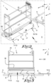
figure 1 shows a perspective view of a possible embodiment of a tube rail cart according to the invention which is put on a pair of tube rails; -
figure 2 shows a perspective view of the tube rail cart standing on a flat surface next to the pair of tube rails; -
figure 3 shows a side view according to the arrow F03 of the tube rail cart offigure 2 ; -
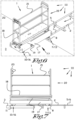
figures 4 and 5 analogously tofigures 2 and 3 show a condition of the tube rail cart whereby drive wheels thereof support on the flat surface and other wheels on tube rails; -
figures 6 and 7 , analogously tofigures 2 and 3 , show a condition of the tube rail cart whereby drive wheels thereof support on tube rails and other wheels on the adjoining, flat surface; -
figures 8 and 9 analogously tofigures 2 and 3 show a condition of the tube rail cart, as shown infigure 1 whereby the tube rail cart stands on a pair of tube rails; -
figure 10 shows a bottom view according to the arrow F10 infigure 3 of the tube rail cart; -
figures 11 and 12 on a larger scale show the wheels indicated infigure 10 respectively with F11 and F12; -
figure 13 shows a perspective view and on an even bigger scale an exploded view of the wheel infigure 12 , to illustrate a possible embodiment of a measurement unit for measuring the rotational speed of said wheel; -
figure 14 shows a side view according to the arrow F14 infigure 13 ; and, -
figures 15 and16 schematically illustrate the operation of a device for determining a condition of the tube rail cart which is provided in the tube rail cart according to the invention. -
Figures 1 to 9 show a possible embodiment of atube rail cart 1 according to the invention in different positions relative to atube rail system 2 and relative to an adjoining,flat surface 3. - Typically, the
flat surface 3 is aconcrete strip 3 that traverses plantings in a greenhouse. - Several such
concrete strips 3 can be provided across the surface area of the greenhouse. - The
tube rail system 2 may, for example, consist ofseveral routes 4 of twoparallel tube rails concrete strip 3 between successive rows of plantings. - The
tube rail cart 1 is provided with apair 7 offront wheels rear wheels tube rail cart 1 can move forward over the pair oftube rails tube rail system 2. - The
pair 7 offront wheels axle 14 and are driven by drivingmeans 15 in the form of anelectric motor 15. - The pair 10 of
rear wheels - This is all illustrated in more detail in the bottom view of
figure 10 . - The
front wheels axle 14, as well as therear wheels chassis 17 of thetube rail cart 1 and they bear saidchassis 17 and in essence the wholetube rail cart 1. - A
work platform 18 is mounted on thechassis 17 which is movable up and down by means of ascissor mechanism 19 which is driven by drivingmeans 20 in the form of anelectric motor 20. - The
work platform 18 is surrounded by amesh 21 and on anend face 22 of themesh 21, control means 23 are provided, with which the up and down movement of thescissor mechanism 19 can be controlled, among other things, and with which thetube rail cart 1 can be driven for a forward or backward movement. - To be able to guarantee a safe operation of the
tube rail cart 1, it is necessary to know the condition of thetube rail cart 1. - More specifically, according to the invention it is intended that the
tube rail cart 1 is equipped with means which can at least distinguish the different conditions of thetube rail cart 1, which are shown infigures 2 to 9 . - A first condition I is illustrated in
figures 2 and 3 , whereby thetube rail cart 1 stands on aconcrete strip 3 orflat surface 3 with thefront wheels rear wheels -
Figures 4 and 5 show a second condition II, whereby
thetube rail cart 1 supports on theflat surface 3 or theconcrete strip 3 with thefront wheels rear wheels - The
figures 6 and 7 show a reverse, third condition III, whereby thetube rail cart 1 supports on the tube rails 5 and 6 with thefront wheels flat surface 3 or theconcrete strip 3 with therear wheels -
Figures 8 and 9 show yet a fourth condition IV, whereby this time thetube rail cart 1 supports on the tube rails with thefront wheels rear wheels 10 and 11 . - The conditions II and III correspond with a transitional condition TC whereby the
tube rail cart 1 travels from theconcrete strip 3 or theflat surface 3 to the tube rails 5 and 6 or whereby reversely thetube rail cart 1 comes off the tube rails 5 and 6 to theflat surface 3 or theconcrete strip 3. - In principle it is also useful for a safe operation of the
tube rail cart 1 to know whether such transitional condition TC relates to a first transitional condition TC-I , whereby thetube rail cart 1 moves from a condition I on theconcrete strip 3 or theflat surface 3 to a condition II on the tube rails 5 and 6, or whether it relates to a second transitional condition TC-II, whereby thetube rail cart 1 moves from a condition II on the tube rails 5 and 6 to a condition I on theconcrete strip 3 or theflat surface 3. - Preferably, the
tube rail cart 1 is also provided with means with which the nature of the transitional condition TC, either a first transitional condition TC-I, or a second transitional condition TC-II, can be measured or determined. - To realise all this, both the
front wheels rear wheels tube rail cart 1 according to the invention are each provided with two axial sections. - The
front wheels axial section 24 with a small diameter D1 and therear wheels axial section 25 with a small diameter D2. - Further, the
front wheels axial section 26 with a big diameter D3 and therear wheels axial section 27 with a big diameter D4. - Preferably, according to the invention the
front wheels rear wheels - Preferably, according to the invention the small diameter D1 and the big diameter D3 of the relevant
axial sections front wheel axial sections rear wheel - This is clearly shown for example in the
figures 11 and 12 . - The purpose is that the
tube rail cart 1 can travel on a pair oftube rails axial sections front wheels rear wheels flat surface 3 orconcrete strip 3 with theaxial sections front wheels rear wheels - To this end it is obviously ensured that the distance E between the
axial sections tube rail cart 1 corresponds with the distance F between the tube rails 5 and 6. - The
tube rail cart 1 according to the invention is further provided with adevice 28 for determining a condition I to IV or a transitional condition TC-I or TC-II of thetube rail cart 1. - A diagram of this is shown in
figure 15 . - The
device 28 comprises ameasurement unit 29 for measuring the rotational speed ω1 of one of thefront wheels measurement unit 30 for measuring the rotational speed ω2 of one of therear wheels - Measuring the rotational speeds ω1 and ω2 is not to be construed literally and can also relate to a parameter such as a frequency or period or any other parameter related with the aforementioned rotational speeds ω1 and ω2.
- The
device 28 further comprises acalculation unit 31 for converting the measured rotational speeds ω1 and ω2 to a determination parameter P. - The
device 28 also comprises adetermination unit 32 which is configured to determine the relevant condition I - IV or TC-I or TC-II of thetube rail cart 1 based on the calculated determination parameter P and which more specifically determines on whichaxial sections 24 to 27 of thefront wheels rear wheels tube rail cart 1 supports when moving forward. - In a preferred embodiment of a
tube rail cart 1 according to the invention, thecalculation unit 31 calculates a determination parameter P which is the ratio between the measured rotational speed ω1 thefront wheels 8 and 9 (or at a parameter related to said rotational speed ω1) and the measured rotational speed ω2 at therear wheels 11 and 12 (or a parameter related to said rotational speed ω2). In short: P = ω1 / ω2. - Preferably, the
determination unit 32 of thedevice 28 hereby verifies, for example in anelectronic calculation section 33 suitable to this end, with which of the following ratios between the diameters D1 to D4 of thewheels - the ratio between the big diameter D4 of the
rear wheels front wheels tube rail cart 1 moves forward with allwheels flat surface 3 or on theconcrete strip 3; - the ratio between the small diameter D2 of the
rear wheels front wheels tube rail cart 1 travels with thefront wheels flat surface 3 and moves forward with therear wheels - the ratio between the big diameter D4 of the
rear wheels front wheels tube rail cart 1 travels with thefront wheels rear wheels flat surface 3; or, - the ratio between the small diameter D2 of the
rear wheels front wheels tube rail cart 1 moves forward with allwheels - The speed of the
tube rail cart 1 during a straight line movement is the same for the wholetube rail cart 1 and if thewheels tube rail cart 1, the ratio between the rotational speeds ω1 and ω2 of thefront wheels rear wheels axial wheel section 24 to 27 on which thetube rail cart 1 supports when moving forward, follows automatically. - To know the sequence of the condition of the
tube rail cart 1, preferably thedevice 28 must regularly ..., i-2, i-1, i, i+1, i+2, ..., for example with an interval ΔT every time, determine the conditions ..., Ci-2, Ci-1, Ci, Ci+1, Ci+2,... of thetube rail cart 1 by executing the aforementioned steps with themeasurement units calculation unit 31 and thedetermination unit 32. - Most preferably, the
device 28 or thedetermination unit 32 is also provided with amemory 34, in which a previous condition Ci-1 is recorded which is determined at a moment i-1 or in which several such previous conditions are recorded. - The intention hereby is that the
determination unit 32 of thedevice 28 performs an additional operation by verifying whether a change in the condition of thetube rail cart 1 occurs, whereby the measured condition Ci at moment i is compared to condition Ci-1 at moment i-1 stored in thememory 34 and it is verified whether these conditions Ci and Ci-1 differ and whereby it is additionally verified, if necessary, what the transitional condition TC is that occurs, more specifically whether it relates to a first transitional condition TC-I from a first condition I to a second condition II or third condition III, according to the transition of thetube rail cart 1 from travelling on aflat surface 3 to travelling on a pair oftube rails tube rail cart 1 from travelling on a pair oftube rails flat surface 3. - Said operations can for example occur in a
separate unit 35 suitable to this end of thedetermination unit 32, which receives input from thememory 34 and thecalculation section 33 of thedetermination unit 32. - The
unit 35 can, for example, be provided with asignal generator 36 for generating anoutput signal 37 depending on the condition Ci and/or transitional condition TC-I or TC-II of thetube rail cart 1 identified by thedetermination unit 32. - The
output signal 37 generated by thesignal generator 36 can hereby be adigital output signal 37, whereby alevel 38 of theoutput signal 37 indicates which condition Ci or TC-I or TC-II thetube rail cart 1 is in. - Obviously many other possibilities and ways to indicate the condition of the
tube rail cart 1 according to the invention are not excluded. -
Figures 13 and 14 also show how ameasurement unit - In the embodiment shown, the
measurement unit 30 of thedevice 28 for measuring the rotational speed of arear wheel inductive sensor 39 which is incorporated in theaxle 40 around which therelevant wheel - In the
relevant wheel 11 or 12 a metal element 41 is further provided which generates one or more pulses per rotation in theinductive sensor 39. - In the embodiment shown in the
figures 13 and 14 this is realised by executing the metal element 41 as a ring 42 withrecesses 43 orradial protrusions 44 which are provided at a regular distance from each other along the contour of the ring 42. - In this case, three
such recesses 43 orprotrusions 44 are provided along the contour, such that in theinductive sensor 39 of themeasurement unit - As already explained in the introduction, preferably the
device 28 for determining a condition Ci or TC-I or TC-II of thetube rail cart 1 is part of asafety system 45 in atube rail cart 1 according to the invention. - By way of example
such safety system 45 is schematically shown infigure 16 . - It is understood that the diagram shown in
figure 16 is only intended to visually represent the different components of asafety system 45 of atube rail cart 1 according to the invention and that a realistic diagram will look far more complicated in reality. - Preferably, the
safety system 45 is hereby also provided with switching means 46 that enable or disable control means 47 for activating and/or deactivatingactuators 48 or regulating means 49 ofactuators 48 of thetube rail cart 1, based on theoutput signal 37 coming from theunit 35 of thedetermination unit 32 sent to the switching means 46. - The
aforementioned actuators 48 can be very diverse and can for example be formed by the most diverse electric motors, jacks, hydraulic cylinders, pneumatic drives or compressed air cylinders and the like, but in the diagram offigure 16 it was chosen to represent theactuators 48 as direct-current motors 48 that are powered by anelectrical power supply 50. - In the same way the control means 47 for activating and deactivating the
actuators 48 may also assume various forms. - Said control means 47 may, for example, consist of control buttons, push-buttons, switches, electronic equipment, computers and the like for operating, enabling or disabling the
aforementioned actuators 48, but infigure 16 they are invariably represented by means of apush button 47. - The upper section of
figure 16 illustrates that the switching means 46 can be used for enabling or disabling control means 47 of driving means 51 for the upward movement and driving means 52 for the downward movement of ascissor mechanism 19 of thetube rail cart 1. - By correctly switching the switching means 46 based on the detected condition, it can be ensured for example that an operator cannot move the
scissor mechanism 19 upward if thetube rail cart 1 is not completely on thetube rail system 2 or on theflat surface 3 or on theconcrete strip 3. - For the sake of simplicity in
figure 16 the driving means 51 for the upward movement and the driving means 52 for the downward movement of thescissor mechanism 19 are drawn as separate driving means. - In practice it typically concerns one and the same motor (or another sort of actuator, such as a hydraulic cylinder) with which both the upward movement and the downward movement can be realised and whereby the downward movement does not necessarily require an active energy source, but for example is realised by letting oil run from a chamber of a hydraulic cylinder into another chamber and the like.
- Enabling or disabling the control means 47 with the switching means 46 is schematically shown by
switches 46 with which the connection with theelectrical power supply 50 can be made or can be interrupted, but in practice totally different ways can of course be applied for enabling or disabling the control means 47. - The lower section of
figure 16 further schematically illustrates that the switching means 46 can also be used for enabling or disabling control means 47 of driving means 53 for the forward drive and driving means 54 for the reverse drive of thewheels 8 and/or 9 and/or for enabling or disabling control means 47 of regulating means 49 for regulating the speed with which the driving means 53 and 54 drive thewheels 8 and/or 9. - The switching means 46 can hereby for example be switched such that the
wheels 8 and/or 9 cannot be driven or can only be driven at a limited speed, when thetube rail cart 1 does not completely rest on thetube rail system 2. - Again, in practice, the driving means 53 and 54 can be formed by one single
electric motor 15, as is the case for example in the embodiment offigure 10 . - In a preferred embodiment of a
tube rail cart 1 according to the invention the switching means 46 or configured to enable or disable the control means 47 for activating and deactivatingactuators 48 based on a condition of thetube rail cart 1 identified by thedevice 28 and according to one or more of the following criteria: - upon identifying a first condition I or fourth condition IV, whereby the
tube rail cart 1 rests completely on aflat surface 3 or completely on the tube rails 5 and 6, enabling or disabling the control means 47 of driving means 51 for the upward movement of ascissor mechanism 19 respectively; - both upon identifying a first condition I and a fourth condition IV, whereby the
tube rail cart 1 rests completely on aflat surface 3 or completely on the tube rails 5 and 6, enabling the control means 47 of driving means 52 for the downward movement of ascissor mechanism 19; and/or - upon identifying a fourth condition IV, whereby the
tube rail cart 1 rests completely on the tube rails 5 and 6, or upon identifying another condition of thetube rail cart 1, enabling or disabling the control means 47 of regulating means 49 to limit the speed of the driving means 53 and/or 54 of thewheels - Generally speaking it is advantageous when the
safety system 45 of atube rail cart 1 according to the invention ensures one or more of the following safeties: - not allowing the
scissor mechanism 19 to move upward as long as allwheels tube rail - not allowing the
wheels tube rail cart 1 forward or backward as long as allwheels tube rail - The present invention is by no means limited to the embodiments of the
tube rail cart 1 according to the invention described by way of example and illustrated with reference to the figures, but suchtube rail cart 1 can be realised in other ways without departing from the scope of the invention defined by the appended claims.
Claims (14)
- Tube rail cart (1) which is intended to be able to move forward on a pair of tube rails (5, 6) of a tube rail system (2), for example of a greenhouse, whereby the tube rail cart (1) is provided with a pair (7) of front wheels (8, 9) and a pair (10) of rear wheels (11, 12), wherein both the front wheels (8, 9) and the rear wheels (11, 12) of the tube rail cart (1) are provided with an axial wheel section (24, 25) with a small diameter (D1, D2) and an axial wheel section (26, 27) with a big diameter (D3, D4), characterized in that the tube rail cart (1) is provided with a device (28) for determining a condition (I-IV, TC-I, TC-II) of the tube rail cart (1), which at least comprises the following elements:- a measurement unit (29) for measuring the rotational speed (ω1) of one of the front wheels (8, 9) or a parameter related to said rotational speed (ω1);- a measurement unit (30) for measuring the rotational speed (ω2) of one of the rear wheels (11, 12) or a parameter related to said rotational speed (ω2);- a calculation unit (31) for converting the measured rotational speeds (ω1, ω2) to a determination parameter (P); and,- a determination unit (32) which is configured to determine the relevant condition (I - IV or TC-I or TC-II) of the tube rail cart (1) based on the calculated determination parameter (P) and which more specifically is configured to determine on which axial section (24 to 27) of the front wheels (8, 9) and the rear wheels (11, 12), the tube rail cart (1) supports when moving forward.
- Tube rail cart (1) according to claim 1, characterised in that the front wheels (8, 9) are executed identically and the rear wheels (11, 12) are executed identically, whereby the small diameter (D1) and the big diameter (D3) of the relevant axial sections (24, 26) of a front wheel (8, 9) and the small diameter (D2) and the big diameter (D4) of the relevant axial sections (25, 27) of a rear wheel (11, 12) all differ from each other.
- Tube rail cart (1) according to claim 1 or 2, characterised in that the determination unit (32) is configured to determine in which of the following conditions the tube rail cart is moving forward:- a first condition (I), whereby the tube rail cart (1) supports on the axial sections of the front wheels (8, 9) with a big diameter and on the axial sections of the rear wheels (11, 12) with a big diameter;- a second condition (I), whereby the tube rail cart (1) supports on the axial sections of the front wheels (8, 9) with a big diameter and on the axial sections of the rear wheels (11, 12) with a small diameter;- a third condition (III), whereby the tube rail cart (1) supports on the axial sections of the front wheels (8, 9) with a small diameter and on the axial sections of the rear wheels (11, 12) with a big diameter; or,- a fourth condition (IV), whereby the tube rail cart (1) supports on the axial sections of the front wheels (8, 9) with a small diameter and on the axial sections of the rear wheels (11, 12) with a small diameter.
- Tube rail cart (1) according to one or more of the previous claims, characterised in that the calculation unit (31) is configured to calculate a determination parameter (P) which is the ratio between the measured rotational speed (ω1) at the front wheels (8, 9) and the measured rotational speed (ω2) at the rear wheels (11, 12) (P = ω1 / ω2).
- Tube rail cart (1) according to claims 2 to 4, characterised in that the determination unit (32) of the device is configured to verify with which of the following ratios between the diameters of the wheels (8, 9, 11, 12) the determination parameter (P) corresponds:- the ratio between the big diameter (D4) of the rear wheels (11, 12) and the big diameter (D3) of the front wheels (8, 9), whereby thus P = D4/D3, according to an aforementioned first condition (I), whereby the tube rail cart (1) moves forward with all wheels (8, 9, 11 and 12) on the flat surface (3) or on the concrete strip (3) ;- the ratio between the small diameter (D2) of the rear wheels (11, 12) and the big diameter (D3) of the front wheels (8, 9), whereby thus P = D2/D3, according to an aforementioned second condition (II), whereby the tube rail cart (1) travels with the front wheels (8, 9) on the flat surface (3) and moves forward with the rear wheels (11, 12) on the tube rails (5, 6);- the ratio between the big diameter (D4) of the rear wheels (11, 12) and the small diameter (D1) of the front wheels (8, 9), whereby thus P = D4/D1, according to an aforementioned third condition (III), whereby the tube rail cart (1) travels with the front wheels (8, 9) on the tube rails (5, 6) and moves forward with the rear wheels (11, 12) on the flat surface (3); or,- the ratio between the small diameter (D2) of the rear wheels (11, 12) and the small diameter (D1) of the front wheels (8, 9), whereby thus P = D2/D1, according to an aforementioned fourth condition (IV) whereby the tube rail cart (1) moves forward with all wheels (8, 9, 11 and 12) on the tube rails (5, 6).
- Tube rail cart (1) according to one or more of the previous claims, characterised in that the tube rail cart (1) is intended to travel with the axial sections (24, 25) with a small diameter (D1, D2) of both the front wheels (8, 9) and the rear wheels (11, 12) on a pair of tube rails (5, 6) and with the axial sections (26, 27) with a big diameter (D3, D4) of both the front wheels (8, 9) and the rear wheels (11, 12) on a flat surface (3).
- Tube rail cart (1) according to claims 3 and 6, characterised in that the device (28) is also provided with a memory (34), whereby the determination unit (32) of the device (28) is configured to verify whether a change in the condition (C) of the tube rail cart (1) occurs and if necessary additionally verifies whether it relates to a first transitional condition (TC-I) from a first condition (I) to a second condition (II) or third condition (III), according to the transition of the tube rail cart (1) from travelling on a flat surface (3) to travelling on a pair of tube rails (5, 6), or whether it relates to a transitional condition (TC-II) from a fourth condition (IV) to a second condition (II) or third condition (III), according to the transition of the tube rail cart (1) from travelling on a pair of tube rails (5, 6) to travelling on a flat surface (3).
- Tube rail cart (1) according to one or more of the previous claims, characterised in that a first pair (7) of wheels (8, 9) of the pair (7) of front wheels (8, 9) and the pair (10) of rear wheels (11, 12) is a driven pair of wheels (13) and whereby a second pair (10) of wheels (11, 12) of the pair (7) of front wheels (8, 9) and the pair (10) of rear wheels (11, 12) is a non-driven pair of idler wheels (16).
- Tube rail cart (1) according to any one of the previous claims, characterised in that at least one measurement unit (29, 30) of the device (28) comprises an inductive sensor (39) which is incorporated in the axle (40) around which the wheel (11, 12) turns, the rotational speed (ω2) of which needs to be measured, whereby an element (41, 42) is provided in the relevant wheel (11, 12) which generates one or more pulses (37) per rotation in the inductive sensor (39).
- Tube rail cart (1) according to any one of the previous claims, characterised in that the device (28) for determining a condition (Ci, TC-I, TC-II) of the tube rail cart (1) is part of a safety system (45) whereby the device (28) is provided with a signal generator (36) for generating an output signal (37) depending on the condition (Ci) and/or transitional condition (TC-I, TC-II) of the tube rail cart (1) identified by the determination unit (32), whereby the safety system (45) further comprises at least switching means (46) which enable or disable control means (47) for activating and/or deactivating actuators (48) or regulating means (49) of actuators (48) of the tube rail cart (1) based on the output signal (37) sent to the switching means (46) .
- Tube rail cart (1) according to claim 10, characterised in that the output signal (37) of the signal generator (36) is a digital output signal (37), whereby a level (38) of the output signal (37) indicates which condition (Ci, TC-I, TC-II) the tube rail cart (1) is in.
- Tube rail cart (1) according to claim 10 or 11, characterised in that the switching means (46) are able to enable or disable one or more of the following control means (47) for activating and deactivating actuators (48):- control means (47) of driving means (53, 54) for driving a driven pair of wheels (8, 9) forwards or backwards;- control means (47) of regulating means (49) for regulating the speed of the driving means (53, 54) of the wheels (8, 9); and/or,- control means (47) of driving means (51, 52) for the upward and/or downward movement of a scissor mechanism (19) .
- Tube rail cart (1) according to one or more of the claims 10 to 12, characterised in that the switching means (46) are configured to enable or disable the control means (47) for activating and deactivating actuators (48) based on a condition (I-IV, TC-I, TC-II) of the tube rail cart (1) determined by the device (28) and according to one or more of the following criteria:- upon identifying a first condition (I) or fourth condition (IV), whereby the tube rail cart (1) rests completely on a flat surface (3) or completely on the tube rails (5, 6), enabling or disabling the control means (47) of driving means (51) for the upward movement of a scissor mechanism (19);- both upon identifying a first condition (I) and a fourth condition (IV), whereby the tube rail cart (1) rests completely on a flat surface (3) or completely on the tube rails (5, 6), enabling the control means (47) of driving means (52) for the downward movement of a scissor mechanism (19); and/or,- upon identifying a fourth condition (IV), whereby the tube rail cart (1) rests completely on the tube rails (5, 6), or upon identifying another condition of the tube rail cart (1), enabling or disabling the control means (47) of regulating means (49) for limiting the speed of the driving means (53, 54) of the wheels (8, 9) .
- Tube rail cart according to claim 12 or 13, characterised in that the safety system (45) of a tube rail cart (1) ensures one or more of the following safeties:- not allowing the scissor mechanism (19) to move upward as long as all wheels (8, 9, 11, 12) are not in contact with a tube rail (5, 6); and/or,- not allowing the wheels (8, 9) to drive the tube rail cart (1) forward or backward as long as all wheels (8, 9, 11, 12) are not in contact with a tube rail (5, 6), or allowing this at a limited speed only).
Applications Claiming Priority (1)
| Application Number | Priority Date | Filing Date | Title |
|---|---|---|---|
| BE20215155A BE1029168B1 (en) | 2021-03-03 | 2021-03-03 | Pipe rail trolley |
Publications (2)
| Publication Number | Publication Date |
|---|---|
| EP4052986A1 EP4052986A1 (en) | 2022-09-07 |
| EP4052986B1 true EP4052986B1 (en) | 2024-04-24 |
Family
ID=74859660
Family Applications (1)
| Application Number | Title | Priority Date | Filing Date |
|---|---|---|---|
| EP22158829.6A Active EP4052986B1 (en) | 2021-03-03 | 2022-02-25 | Tube rail cart |
Country Status (2)
| Country | Link |
|---|---|
| EP (1) | EP4052986B1 (en) |
| BE (1) | BE1029168B1 (en) |
Family Cites Families (2)
| Publication number | Priority date | Publication date | Assignee | Title |
|---|---|---|---|---|
| NL1014556C2 (en) * | 2000-03-03 | 2001-09-10 | Koat B V | Working carriage platform for greenhouse industry, runs through greenhouse supported by heating medium pipes and has stabilization system |
| CA3031875A1 (en) * | 2019-01-28 | 2020-07-28 | 1753429 Ontario Inc. | Transportation system |
-
2021
- 2021-03-03 BE BE20215155A patent/BE1029168B1/en active IP Right Grant
-
2022
- 2022-02-25 EP EP22158829.6A patent/EP4052986B1/en active Active
Also Published As
| Publication number | Publication date |
|---|---|
| BE1029168A1 (en) | 2022-09-27 |
| BE1029168B1 (en) | 2022-10-03 |
| EP4052986A1 (en) | 2022-09-07 |
Similar Documents
| Publication | Publication Date | Title |
|---|---|---|
| CN106604886B (en) | Fork truck with optics cargo sensing structure | |
| US4137984A (en) | Self-guided automatic load transporter | |
| CN103097279B (en) | Machine, controller, and control method | |
| US10599157B2 (en) | Autonomous movement system | |
| US8230976B2 (en) | Pallet truck with calculated fork carriage height | |
| KR100200188B1 (en) | Scissor lift control apparatus and method | |
| DE602005006784D1 (en) | MACHINE WITH OWN DRIVE FOR THE TRANSFORMATION OF STACKED LOADS WITH PROTECTIVE FILM | |
| EP3410248A1 (en) | Multiple zone sensing for materials handling vehicles | |
| KR20090031344A (en) | Variable path automated guided vehicle | |
| CN102341325B (en) | Moving shelf equipment | |
| BE1020545A3 (en) | TUBE TRAILER. | |
| EP2354078A1 (en) | Industrial truck | |
| KR101864712B1 (en) | Multi-function agricultural automatic guide vehicle of wheel-rail combined type | |
| EP4052986B1 (en) | Tube rail cart | |
| JP2006248746A (en) | Device for moving at elevated spot on article shelf | |
| EP3521235A1 (en) | Material handling vehicle | |
| EP3606862B1 (en) | Crane with anti-tipping control system | |
| EP4075945B1 (en) | Two-way horticulture trolley with individually turnable floor-wheels | |
| JP2011132002A (en) | Reach forklift truck | |
| JP2003212498A (en) | Forklift travel control device | |
| CN216472064U (en) | Fork truck structure with adjustable axle distance | |
| JP2003212499A (en) | Forklift travel control device | |
| JP4844826B2 (en) | Goods storage equipment | |
| JP5003927B2 (en) | Article transfer device | |
| CN113979363A (en) | Forklift structure with adjustable axle distance |
Legal Events
| Date | Code | Title | Description |
|---|---|---|---|
| PUAI | Public reference made under article 153(3) epc to a published international application that has entered the european phase |
Free format text: ORIGINAL CODE: 0009012 |
|
| STAA | Information on the status of an ep patent application or granted ep patent |
Free format text: STATUS: THE APPLICATION HAS BEEN PUBLISHED |
|
| AK | Designated contracting states |
Kind code of ref document: A1 Designated state(s): AL AT BE BG CH CY CZ DE DK EE ES FI FR GB GR HR HU IE IS IT LI LT LU LV MC MK MT NL NO PL PT RO RS SE SI SK SM TR |
|
| STAA | Information on the status of an ep patent application or granted ep patent |
Free format text: STATUS: REQUEST FOR EXAMINATION WAS MADE |
|
| 17P | Request for examination filed |
Effective date: 20230124 |
|
| RBV | Designated contracting states (corrected) |
Designated state(s): AL AT BE BG CH CY CZ DE DK EE ES FI FR GB GR HR HU IE IS IT LI LT LU LV MC MK MT NL NO PL PT RO RS SE SI SK SM TR |
|
| GRAP | Despatch of communication of intention to grant a patent |
Free format text: ORIGINAL CODE: EPIDOSNIGR1 |
|
| STAA | Information on the status of an ep patent application or granted ep patent |
Free format text: STATUS: GRANT OF PATENT IS INTENDED |
|
| RIC1 | Information provided on ipc code assigned before grant |
Ipc: A01G 9/14 20060101ALI20231218BHEP Ipc: B66F 11/04 20060101ALI20231218BHEP Ipc: B65G 41/02 20060101ALI20231218BHEP Ipc: B65G 1/04 20060101ALI20231218BHEP Ipc: B60B 17/00 20060101ALI20231218BHEP Ipc: B61F 13/00 20060101ALI20231218BHEP Ipc: B61D 15/00 20060101AFI20231218BHEP |
|
| INTG | Intention to grant announced |
Effective date: 20240116 |
|
| GRAS | Grant fee paid |
Free format text: ORIGINAL CODE: EPIDOSNIGR3 |
|
| GRAA | (expected) grant |
Free format text: ORIGINAL CODE: 0009210 |
|
| STAA | Information on the status of an ep patent application or granted ep patent |
Free format text: STATUS: THE PATENT HAS BEEN GRANTED |
|
| P01 | Opt-out of the competence of the unified patent court (upc) registered |
Effective date: 20240225 |
|
| AK | Designated contracting states |
Kind code of ref document: B1 Designated state(s): AL AT BE BG CH CY CZ DE DK EE ES FI FR GB GR HR HU IE IS IT LI LT LU LV MC MK MT NL NO PL PT RO RS SE SI SK SM TR |
|
| REG | Reference to a national code |
Ref country code: GB Ref legal event code: FG4D |
|
| REG | Reference to a national code |
Ref country code: CH Ref legal event code: EP |
|
| REG | Reference to a national code |
Ref country code: DE Ref legal event code: R096 Ref document number: 602022002972 Country of ref document: DE |
|
| REG | Reference to a national code |
Ref country code: IE Ref legal event code: FG4D |