EP4052944A1 - Elektrofahrzeug mit feststellbremsanordnung sowie verwendung einer bremssattel-bremsscheiben-anordnung zum feststellen einer abtriebswelle eines elektromotors - Google Patents
Elektrofahrzeug mit feststellbremsanordnung sowie verwendung einer bremssattel-bremsscheiben-anordnung zum feststellen einer abtriebswelle eines elektromotors Download PDFInfo
- Publication number
- EP4052944A1 EP4052944A1 EP22020090.1A EP22020090A EP4052944A1 EP 4052944 A1 EP4052944 A1 EP 4052944A1 EP 22020090 A EP22020090 A EP 22020090A EP 4052944 A1 EP4052944 A1 EP 4052944A1
- Authority
- EP
- European Patent Office
- Prior art keywords
- output shaft
- brake
- collar
- arrangement
- parking brake
- Prior art date
- Legal status (The legal status is an assumption and is not a legal conclusion. Google has not performed a legal analysis and makes no representation as to the accuracy of the status listed.)
- Withdrawn
Links
- 230000004913 activation Effects 0.000 description 4
- 238000000034 method Methods 0.000 description 3
- 208000012886 Vertigo Diseases 0.000 description 1
- 230000003213 activating effect Effects 0.000 description 1
- 230000001419 dependent effect Effects 0.000 description 1
- 238000005096 rolling process Methods 0.000 description 1
Images


Classifications
-
- B—PERFORMING OPERATIONS; TRANSPORTING
- B60—VEHICLES IN GENERAL
- B60K—ARRANGEMENT OR MOUNTING OF PROPULSION UNITS OR OF TRANSMISSIONS IN VEHICLES; ARRANGEMENT OR MOUNTING OF PLURAL DIVERSE PRIME-MOVERS IN VEHICLES; AUXILIARY DRIVES FOR VEHICLES; INSTRUMENTATION OR DASHBOARDS FOR VEHICLES; ARRANGEMENTS IN CONNECTION WITH COOLING, AIR INTAKE, GAS EXHAUST OR FUEL SUPPLY OF PROPULSION UNITS IN VEHICLES
- B60K1/00—Arrangement or mounting of electrical propulsion units
-
- B—PERFORMING OPERATIONS; TRANSPORTING
- B60—VEHICLES IN GENERAL
- B60K—ARRANGEMENT OR MOUNTING OF PROPULSION UNITS OR OF TRANSMISSIONS IN VEHICLES; ARRANGEMENT OR MOUNTING OF PLURAL DIVERSE PRIME-MOVERS IN VEHICLES; AUXILIARY DRIVES FOR VEHICLES; INSTRUMENTATION OR DASHBOARDS FOR VEHICLES; ARRANGEMENTS IN CONNECTION WITH COOLING, AIR INTAKE, GAS EXHAUST OR FUEL SUPPLY OF PROPULSION UNITS IN VEHICLES
- B60K17/00—Arrangement or mounting of transmissions in vehicles
-
- B—PERFORMING OPERATIONS; TRANSPORTING
- B60—VEHICLES IN GENERAL
- B60T—VEHICLE BRAKE CONTROL SYSTEMS OR PARTS THEREOF; BRAKE CONTROL SYSTEMS OR PARTS THEREOF, IN GENERAL; ARRANGEMENT OF BRAKING ELEMENTS ON VEHICLES IN GENERAL; PORTABLE DEVICES FOR PREVENTING UNWANTED MOVEMENT OF VEHICLES; VEHICLE MODIFICATIONS TO FACILITATE COOLING OF BRAKES
- B60T1/00—Arrangements of braking elements, i.e. of those parts where braking effect occurs specially for vehicles
- B60T1/02—Arrangements of braking elements, i.e. of those parts where braking effect occurs specially for vehicles acting by retarding wheels
- B60T1/06—Arrangements of braking elements, i.e. of those parts where braking effect occurs specially for vehicles acting by retarding wheels acting otherwise than on tread, e.g. employing rim, drum, disc, or transmission or on double wheels
- B60T1/065—Arrangements of braking elements, i.e. of those parts where braking effect occurs specially for vehicles acting by retarding wheels acting otherwise than on tread, e.g. employing rim, drum, disc, or transmission or on double wheels employing disc
Definitions
- the invention relates to the use of a brake caliper/brake disc assembly. Furthermore, the invention relates to a parking brake device for an electric vehicle.
- the invention proposes the use of a known brake arrangement as a parking brake arrangement for electric vehicles, as well as a new type of automatic system, such as a brake that has not previously been arranged in this way engages in the drive system of the vehicle.
- the parking brake arrangement according to the invention is assigned directly to at least one electric motor (20) which has at least one output shaft (24).
- the output shaft (24) has a radially outwardly extending collar (28).
- the collar (28) can be locked radially on the outside at least on one side and/or from radially on the outside against further rotation by means of a locking device and in particular by means of a locking element coming into direct contact with the collar.
- the collar (28) is designed in one piece with the output shaft (24), in particular molded on.
- a disk is pushed onto the output shaft (24) as a collar (28), in particular with a press fit.
- the output shaft (24) is designed as a flange, in particular as a cardan shaft flange (32).
- the collar (28) is clamped between the output shaft flange (26) and the cardan shaft flange (32).
- the locking element of a conventional brake shoe arrangement encompasses the collar (28) from the radial outside.
- Brake shoes are particularly preferably arranged exclusively in a single brake caliper, so that the collar (28) can nevertheless be securely fixed axially from both sides, particularly preferably by means of a spindle that can be rotated parallel to the motor axis.
- Its output shaft (24) has, for example, a radially outwardly extending collar (28) which can be blocked to directly secure the output shaft (24) and thus at least one output train with ground contact.
- the basic function must always be present. According to the invention, at least one activation condition must then be met so that the parking brake engages.
Landscapes
- Engineering & Computer Science (AREA)
- Transportation (AREA)
- Mechanical Engineering (AREA)
- Chemical & Material Sciences (AREA)
- Combustion & Propulsion (AREA)
- Braking Arrangements (AREA)
Abstract
Description
- Die Erfindung betrifft eine Verwendung einer Bremssattel-Bremsscheiben-Anordnung. Ferner betrifft die Erfindung eine Feststellbremseinrichtung für ein Elektrofahrzeug.
- Elektrofahrzeuge können derzeit je nach Ausstattung ungewollt wegrollen oder weiterrollen, insbesondere in Zustellarbeitsabläufen. Es ist daher eine Aufgabe, Straßenverkehrsteilnehmer besser vor einem ungewollten Wegrollen eines Elektrofahrzeugs zu schützen. Da in Elektrofahrzeugen oft kein Getriebe verbaut ist, fallen bisher genutzte Feststelloptionen, wie das Gang einlegen, weg.
- Die Erfindung schlägt eine Verwendung einer bekannten Bremsanordnung als Feststellbremsanordnung für Elektrofahrzeuge sowie eine neuartige Automatik vor, wie eine bisher so nicht angeordnete Bremse in das Antriebssystem des Fahrzeugs greift.
- Eine erfindungsgemäße Verwendung ist in Anspruch 1 angegeben und hiermit per Verweis zu einem Bestandteil der Beschreibung gemacht. Gleiches gilt für die erfindungsgemäße Feststellbremsanordnung nach Anspruch 2 sowie das Elektrofahrzeug nach Anspruch 7.
- Vorteilhafte Ausführungsformen sind den Unteransprüchen sowie der nachfolgenden Figurenbeschreibung und eine besonders bevorzugte Ausführungsform den
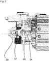
Figuren 1 bis 3 selbst zu entnehmen. - Die erfindungsgemäße Feststellbremsanordnung ist direkt zumindest einem Elektromotor (20) zugeordnet, der zumindest eine Abtriebswelle (24) aufweist. Die Abtriebswelle (24) weist einen sich radial nach außen erstreckenden Kragen (28) auf. Der Kragen (28) ist radial außen zumindest auf einer Seite und / oder von radial außen mittels einer Feststelleinrichtung und insbesondere mittels eines in direkten Kontakt mit dem Kragen tretenden Feststellelements gegen weitere Rotation sperrbar.
- Gemäß einer vorteilhaften Ausführungsform ist der Kragen (28) einteilig mit der Abtriebswelle (24) ausgeführt, insbesondere angeformt.
- Gemäß einer weiteren vorteilhaften Ausführungsform ist eine Scheibe als Kragen (28) auf die Abtriebswelle (24) aufgeschoben, insbesondere mit Presspassung.
- Gemäß einer weiteren vorteilhaften Ausführungsform ist die Abtriebswelle (24) als ein Flansch, insbesondere als ein Kardanwellenflansch (32), ausgebildet. Der Kragen (28) ist dabei zwischen Abtriebswellenflansch (26) und Kardanwellenflansch (32) eingespannt.
- Gemäß einer weiteren vorteilhaften Ausführungsform umgreift das Feststellelement einer üblichen Bremsbacken-Anordnung von radial außen den Kragen (28). Besonders bevorzugt sind es ausschließlich in einem einzigen Bremssattel angeordnete Bremsbacken, sodass der Kragen (28) dennoch sicher axial von beiden Seiten feststellbar ist, besonders bevorzugt mittels einer parallel zur Motorachse verdrehbaren Spindel.
- An der Motoranbindung 26, 32 zur Kardanwelle 30 wird in dem besonders bevorzugten Ausführungsbeispiel nach den
Figuren 1 bis 3 eine "Bremsscheibe" als ein Kragen 28 der Abtriebswelle 24 montiert. Diese wird mit einem elektronischen Bremssattel nach Festlegung definierter Bedingungen gegriffen. Dadurch kann die Kardanwelle nicht mehr frei oder beinahe frei drehen, wie es ihr in herkömmlichen Elektromotoren sonst erlaubt bliebe. Resultierend daraus ist im Fall eines bevorzugten Ausführungsbeispiels eines nicht näher dargestellten Elektrofahrzeugs mit einer solchen Elektromotoreinbindung, dass die Räder der Hinterachse blockiert sind, ebenfalls nicht mehr drehen und das Fahrzeug somit sicher und gebremst steht. - Seine Abtriebswelle (24) weist beispielsweise einen sich radial nach außen erstreckenden Kragen (28) auf, der zum direkten Feststellen der Abtriebswelle (24) und mithin zumindest eines Abtriebsstranges mit Bodenkontakt blockierbar ist.
- Die Erfindung schlägt in besonderen Ausführungsformen, insbesondere auch bevorzugter Verfahren zur Sicherung eines Elektrofahrzeugs, folgende Bedingungen vor, wie und wann die Bremse greifen soll. Nach Festlegung einer Basisfunktion kann das im Rahmen der Erfindung in besonders bevorzugten Ausführungsformen mit verschiedenen weiteren Funktionen erweitert werden:
- Basisbedingungen:
- Das Fahrzeug muss bereits vor dem Auslösen der Feststellbetätigung stehen.
- Der Motor muss ohne Drehmoment sein.
- Der Motor darf sich nicht drehen, was ggf. aber zwangsweise an Basisbedingung 1 gekoppelt ist.
- Aktivierungsbedingungen in Verbindung mit der Basisbedingung:
- Die "Zündung" des Fahrzeugs muss ausgeschaltet sein.
- Ein Druckschalter im Fahrersitz schaltet, sobald der/die Fahrer/-in vom Fahrersitz aufsteht.
- Die Fahrertür wird geöffnet.
- Die Basisfunktion muss immer vorhanden sein. Damit die Feststellbremse greift muss dann erfindungsgemäß mindestens eine Aktivierungsbedingung gegeben sein.
- Technischer Ablauf im Fall einer bevorzugten Ausführungsform: Wenn die Bedingung für ein Aktivieren der Feststellbremse gegeben ist, wird der Motor des Bremssattels bestromt, bis die Bremse komplett gegriffen hat. In diesem verschlossenen Zustand bleibt die Feststellbremse, bis alle Aktivierungsbedingungen deaktiviert sind. Wenn alle Aktivierungsbedingungen deaktiviert sind, wird der Motor des Bremssattels in umgepolter Richtung bestromt, der Zylinder des Bremssattels fährt zurück, öffnet die Bremse und das Fahrzeug kann wieder bewegt werden.
-
- 10
- Fahrzeuggestell
- 20
- Elektromotor
- 22
- Motoraufnahme
- 24
- Abtriebswelle
- 25
- Lücke
- 26
- Abtriebswellenflansch
- 28
- Kragen
- 30
- Kardanwelle
- 32
- Kardanwellenflansch
Claims (7)
- Verwendung einer Bremssattel-Bremsscheiben-Anordnung zum Feststellen einer Abtriebswelle (24).
- Feststellbremsanordnung, mit einem Elektromotor (20), der zumindest eine Abtriebswelle (24) aufweist, dessen Abtriebswelle (24) einen sich radial nach außen erstreckenden Kragen (28) aufweist, welcher Kragen (28) radial außen zumindest auf einer Seite oder von radial außen mittels eines Feststellelements gegen weitere Rotation sperrbar ist.
- Feststellbremsanordnung nach Anspruch 2
dadurch gekennzeichnet, dass
der Kragen (28) einteilig mit der Abtriebswelle (24) ausgeführt ist, insbesondere angeformt. - Feststellbremsanordnung nach Anspruch 2
dadurch gekennzeichnet, dass
eine Scheibe als Kragen (28) auf die Abtriebswelle (24) aufgeschoben ist, insbesondere als Presspassung. - Feststellbremsanordnung nach Anspruch 2
dadurch gekennzeichnet, dass
die Abtriebswelle (24) als ein Flansch, insbesondere als ein Kardanwellenflansch (32), ausgebildet ist und dass der Kragen (28) zwischen Abtriebswellenflansch (26) und Kardanwellenflansch (32) eingespannt ist. - Feststellbremsanordnung nach Anspruch 2
dadurch gekennzeichnet, dass
das Feststellelement eine übliche Bremsbacken-Anordnung in einem von radial außen den Kragen (28) umgreifenden Bremssattel ist, sodass der Kragen (28) axial von beiden Seiten feststellbar ist. - Elektrofahrzeug mit einer Feststellbremsanordnung nach einem der Ansprüche 2 bis 6.
Applications Claiming Priority (1)
| Application Number | Priority Date | Filing Date | Title |
|---|---|---|---|
| DE102021105308.0A DE102021105308A1 (de) | 2021-03-04 | 2021-03-04 | Elektrofahrzeug mit Feststellbremsanordnung sowie Verwendung einer Bremssattel-Bremsscheiben-Anordnung zum Feststellen einer Abtriebswelle eines Elektromotors |
Publications (1)
| Publication Number | Publication Date |
|---|---|
| EP4052944A1 true EP4052944A1 (de) | 2022-09-07 |
Family
ID=80682426
Family Applications (1)
| Application Number | Title | Priority Date | Filing Date |
|---|---|---|---|
| EP22020090.1A Withdrawn EP4052944A1 (de) | 2021-03-04 | 2022-03-04 | Elektrofahrzeug mit feststellbremsanordnung sowie verwendung einer bremssattel-bremsscheiben-anordnung zum feststellen einer abtriebswelle eines elektromotors |
Country Status (2)
| Country | Link |
|---|---|
| EP (1) | EP4052944A1 (de) |
| DE (1) | DE102021105308A1 (de) |
Citations (2)
| Publication number | Priority date | Publication date | Assignee | Title |
|---|---|---|---|---|
| AT12010U2 (de) * | 2011-04-04 | 2011-09-15 | Ve Vienna Engineering Forschungs Und Entwicklungs Gmbh | Elektrofahrzeug mit radindividuellen reibungsbremsen und radindividuellem antrieb und bremsverfahren dafür |
| US20190078672A1 (en) * | 2017-09-08 | 2019-03-14 | Guangzhou Sunmile Dynamic Technologies Corp., Ltd | Four-Speed Transaxle for Electric Vehicle |
-
2021
- 2021-03-04 DE DE102021105308.0A patent/DE102021105308A1/de not_active Withdrawn
-
2022
- 2022-03-04 EP EP22020090.1A patent/EP4052944A1/de not_active Withdrawn
Patent Citations (2)
| Publication number | Priority date | Publication date | Assignee | Title |
|---|---|---|---|---|
| AT12010U2 (de) * | 2011-04-04 | 2011-09-15 | Ve Vienna Engineering Forschungs Und Entwicklungs Gmbh | Elektrofahrzeug mit radindividuellen reibungsbremsen und radindividuellem antrieb und bremsverfahren dafür |
| US20190078672A1 (en) * | 2017-09-08 | 2019-03-14 | Guangzhou Sunmile Dynamic Technologies Corp., Ltd | Four-Speed Transaxle for Electric Vehicle |
Also Published As
| Publication number | Publication date |
|---|---|
| DE102021105308A1 (de) | 2022-09-08 |
Similar Documents
| Publication | Publication Date | Title |
|---|---|---|
| DE10150803B4 (de) | Hydraulische Fahrzeugbremse mit elektrisch betätigbarer Feststelleinrichtung | |
| EP3867113B1 (de) | Verfahren zum verzögern eines kraftfahrzeugs bei einer notbremsung und kraftfahrzeug | |
| DE102018212954B4 (de) | Radgewichtsanordnung | |
| EP2611625B1 (de) | Radbaugruppe für kraftfahrzeuge | |
| DE3910369A1 (de) | Sicherheitseinrichtung | |
| EP2962865A1 (de) | Nabenanordnung, insbesondere für zwillingsräder | |
| WO2023031194A1 (de) | Elektrofahrzeug mit mindestens einem bremssystem und verfahren zum betreiben eines elektrofahrzeugs | |
| EP2510255B1 (de) | Radnabenantriebseinheit | |
| WO1999030056A1 (de) | Sicherheitseinrichtung für ein getriebe | |
| DE102012219903A1 (de) | Radnabe eines Kraftfahrzeugs | |
| WO2020020402A1 (de) | Nehmerzylinder mit einer über einen arretierungsring an einem kolben angebrachten dichtung; betätigungseinrichtung sowie kupplungssystem | |
| EP4052944A1 (de) | Elektrofahrzeug mit feststellbremsanordnung sowie verwendung einer bremssattel-bremsscheiben-anordnung zum feststellen einer abtriebswelle eines elektromotors | |
| DE102021205741B3 (de) | Abstellmodul für einen Antriebsstrangprüfstand | |
| DE102018129157A1 (de) | Bremsanordnung für ein Laufrad eines Rollstuhls, Laufrad und Rollstuhl | |
| DE1922964C3 (de) | Selbstsperrendes Kegelradausgleichsgetriebe | |
| DE102018130819B4 (de) | Elektrische Achsantriebseinheit mit integrierter Bremseinrichtung | |
| EP2559581A2 (de) | Antriebssystem für ein Kraftfahrzeug mit einem als Sperrdifferential wirkenden Bremssystem | |
| DE102019100738B3 (de) | Elektrische Achsantriebseinheit mit integrierter Bremseinrichtung mit axial beweglichem Bremsscheibenelement | |
| DE102019118828A1 (de) | Parksperrenvorrichtung für eine elektrische Antriebsachse und elektrische Antriebsachse mit einer Parksperrenvorrichtung | |
| DE102023001258A1 (de) | Elektrischer Radnabenantrieb für ein Kraftfahrzeug, insbesondere für einen Kraftwagen | |
| WO2023126236A1 (de) | Radnabenantrieb für ein kraftfahrzeug, insbesondere für einen kraftwagen, sowie kraftfahrzeug | |
| DE102009055348A1 (de) | Schleuderscheibe, zugehörige Fluidpumpe für ein Fluidaggregat und zugehöriges Fluidaggregat | |
| DE102018217084B4 (de) | Antriebsanordnung für ein Kraftfahrzeug | |
| DE9406795U1 (de) | Innerer Bremsen-Entlüftungs-Filterring für Kraftfahrzeug-Bremsanlagen, insbesondere Kraftfahrzeuge mit Scheibenbremsen | |
| DE102012015199B4 (de) | Nabenanordnung, insbesondere für Zwillingsräder |
Legal Events
| Date | Code | Title | Description |
|---|---|---|---|
| PUAI | Public reference made under article 153(3) epc to a published international application that has entered the european phase |
Free format text: ORIGINAL CODE: 0009012 |
|
| STAA | Information on the status of an ep patent application or granted ep patent |
Free format text: STATUS: THE APPLICATION HAS BEEN PUBLISHED |
|
| AK | Designated contracting states |
Kind code of ref document: A1 Designated state(s): AL AT BE BG CH CY CZ DE DK EE ES FI FR GB GR HR HU IE IS IT LI LT LU LV MC MK MT NL NO PL PT RO RS SE SI SK SM TR |
|
| STAA | Information on the status of an ep patent application or granted ep patent |
Free format text: STATUS: REQUEST FOR EXAMINATION WAS MADE |
|
| 17P | Request for examination filed |
Effective date: 20230306 |
|
| RBV | Designated contracting states (corrected) |
Designated state(s): AL AT BE BG CH CY CZ DE DK EE ES FI FR GB GR HR HU IE IS IT LI LT LU LV MC MK MT NL NO PL PT RO RS SE SI SK SM TR |
|
| REG | Reference to a national code |
Ref country code: DE Ref legal event code: R079 Free format text: PREVIOUS MAIN CLASS: B60K0007000000 Ipc: B60K0001000000 |
|
| GRAP | Despatch of communication of intention to grant a patent |
Free format text: ORIGINAL CODE: EPIDOSNIGR1 |
|
| STAA | Information on the status of an ep patent application or granted ep patent |
Free format text: STATUS: GRANT OF PATENT IS INTENDED |
|
| RIC1 | Information provided on ipc code assigned before grant |
Ipc: B60T 1/06 20060101ALI20230817BHEP Ipc: B60K 17/00 20060101ALI20230817BHEP Ipc: B60K 1/00 20060101AFI20230817BHEP |
|
| GRAJ | Information related to disapproval of communication of intention to grant by the applicant or resumption of examination proceedings by the epo deleted |
Free format text: ORIGINAL CODE: EPIDOSDIGR1 |
|
| STAA | Information on the status of an ep patent application or granted ep patent |
Free format text: STATUS: REQUEST FOR EXAMINATION WAS MADE |
|
| STAA | Information on the status of an ep patent application or granted ep patent |
Free format text: STATUS: EXAMINATION IS IN PROGRESS |
|
| INTG | Intention to grant announced |
Effective date: 20230908 |
|
| 17Q | First examination report despatched |
Effective date: 20230929 |
|
| INTC | Intention to grant announced (deleted) | ||
| GRAP | Despatch of communication of intention to grant a patent |
Free format text: ORIGINAL CODE: EPIDOSNIGR1 |
|
| STAA | Information on the status of an ep patent application or granted ep patent |
Free format text: STATUS: GRANT OF PATENT IS INTENDED |
|
| INTG | Intention to grant announced |
Effective date: 20240311 |
|
| STAA | Information on the status of an ep patent application or granted ep patent |
Free format text: STATUS: THE APPLICATION IS DEEMED TO BE WITHDRAWN |
|
| 18D | Application deemed to be withdrawn |
Effective date: 20240712 |