EP4052943A1 - Commande d'un groupe motopropulseur d'un véhicule automobile hybride fonctionnant dans un mode série à batterie déconnectée - Google Patents
Commande d'un groupe motopropulseur d'un véhicule automobile hybride fonctionnant dans un mode série à batterie déconnectée Download PDFInfo
- Publication number
- EP4052943A1 EP4052943A1 EP22157313.2A EP22157313A EP4052943A1 EP 4052943 A1 EP4052943 A1 EP 4052943A1 EP 22157313 A EP22157313 A EP 22157313A EP 4052943 A1 EP4052943 A1 EP 4052943A1
- Authority
- EP
- European Patent Office
- Prior art keywords
- heat engine
- torque
- voltage bus
- rotational speed
- target
- Prior art date
- Legal status (The legal status is an assumption and is not a legal conclusion. Google has not performed a legal analysis and makes no representation as to the accuracy of the status listed.)
- Granted
Links
Images


Classifications
-
- B—PERFORMING OPERATIONS; TRANSPORTING
- B60—VEHICLES IN GENERAL
- B60K—ARRANGEMENT OR MOUNTING OF PROPULSION UNITS OR OF TRANSMISSIONS IN VEHICLES; ARRANGEMENT OR MOUNTING OF PLURAL DIVERSE PRIME-MOVERS IN VEHICLES; AUXILIARY DRIVES FOR VEHICLES; INSTRUMENTATION OR DASHBOARDS FOR VEHICLES; ARRANGEMENTS IN CONNECTION WITH COOLING, AIR INTAKE, GAS EXHAUST OR FUEL SUPPLY OF PROPULSION UNITS IN VEHICLES
- B60K6/00—Arrangement or mounting of plural diverse prime-movers for mutual or common propulsion, e.g. hybrid propulsion systems comprising electric motors and internal combustion engines
- B60K6/20—Arrangement or mounting of plural diverse prime-movers for mutual or common propulsion, e.g. hybrid propulsion systems comprising electric motors and internal combustion engines the prime-movers consisting of electric motors and internal combustion engines, e.g. HEVs
- B60K6/42—Arrangement or mounting of plural diverse prime-movers for mutual or common propulsion, e.g. hybrid propulsion systems comprising electric motors and internal combustion engines the prime-movers consisting of electric motors and internal combustion engines, e.g. HEVs characterised by the architecture of the hybrid electric vehicle
- B60K6/44—Series-parallel type
- B60K6/442—Series-parallel switching type
-
- B—PERFORMING OPERATIONS; TRANSPORTING
- B60—VEHICLES IN GENERAL
- B60K—ARRANGEMENT OR MOUNTING OF PROPULSION UNITS OR OF TRANSMISSIONS IN VEHICLES; ARRANGEMENT OR MOUNTING OF PLURAL DIVERSE PRIME-MOVERS IN VEHICLES; AUXILIARY DRIVES FOR VEHICLES; INSTRUMENTATION OR DASHBOARDS FOR VEHICLES; ARRANGEMENTS IN CONNECTION WITH COOLING, AIR INTAKE, GAS EXHAUST OR FUEL SUPPLY OF PROPULSION UNITS IN VEHICLES
- B60K6/00—Arrangement or mounting of plural diverse prime-movers for mutual or common propulsion, e.g. hybrid propulsion systems comprising electric motors and internal combustion engines
- B60K6/20—Arrangement or mounting of plural diverse prime-movers for mutual or common propulsion, e.g. hybrid propulsion systems comprising electric motors and internal combustion engines the prime-movers consisting of electric motors and internal combustion engines, e.g. HEVs
- B60K6/22—Arrangement or mounting of plural diverse prime-movers for mutual or common propulsion, e.g. hybrid propulsion systems comprising electric motors and internal combustion engines the prime-movers consisting of electric motors and internal combustion engines, e.g. HEVs characterised by apparatus, components or means specially adapted for HEVs
- B60K6/36—Arrangement or mounting of plural diverse prime-movers for mutual or common propulsion, e.g. hybrid propulsion systems comprising electric motors and internal combustion engines the prime-movers consisting of electric motors and internal combustion engines, e.g. HEVs characterised by apparatus, components or means specially adapted for HEVs characterised by the transmission gearings
-
- B—PERFORMING OPERATIONS; TRANSPORTING
- B60—VEHICLES IN GENERAL
- B60K—ARRANGEMENT OR MOUNTING OF PROPULSION UNITS OR OF TRANSMISSIONS IN VEHICLES; ARRANGEMENT OR MOUNTING OF PLURAL DIVERSE PRIME-MOVERS IN VEHICLES; AUXILIARY DRIVES FOR VEHICLES; INSTRUMENTATION OR DASHBOARDS FOR VEHICLES; ARRANGEMENTS IN CONNECTION WITH COOLING, AIR INTAKE, GAS EXHAUST OR FUEL SUPPLY OF PROPULSION UNITS IN VEHICLES
- B60K6/00—Arrangement or mounting of plural diverse prime-movers for mutual or common propulsion, e.g. hybrid propulsion systems comprising electric motors and internal combustion engines
- B60K6/20—Arrangement or mounting of plural diverse prime-movers for mutual or common propulsion, e.g. hybrid propulsion systems comprising electric motors and internal combustion engines the prime-movers consisting of electric motors and internal combustion engines, e.g. HEVs
- B60K6/22—Arrangement or mounting of plural diverse prime-movers for mutual or common propulsion, e.g. hybrid propulsion systems comprising electric motors and internal combustion engines the prime-movers consisting of electric motors and internal combustion engines, e.g. HEVs characterised by apparatus, components or means specially adapted for HEVs
- B60K6/38—Arrangement or mounting of plural diverse prime-movers for mutual or common propulsion, e.g. hybrid propulsion systems comprising electric motors and internal combustion engines the prime-movers consisting of electric motors and internal combustion engines, e.g. HEVs characterised by apparatus, components or means specially adapted for HEVs characterised by the driveline clutches
- B60K6/387—Actuated clutches, i.e. clutches engaged or disengaged by electric, hydraulic or mechanical actuating means
-
- B—PERFORMING OPERATIONS; TRANSPORTING
- B60—VEHICLES IN GENERAL
- B60K—ARRANGEMENT OR MOUNTING OF PROPULSION UNITS OR OF TRANSMISSIONS IN VEHICLES; ARRANGEMENT OR MOUNTING OF PLURAL DIVERSE PRIME-MOVERS IN VEHICLES; AUXILIARY DRIVES FOR VEHICLES; INSTRUMENTATION OR DASHBOARDS FOR VEHICLES; ARRANGEMENTS IN CONNECTION WITH COOLING, AIR INTAKE, GAS EXHAUST OR FUEL SUPPLY OF PROPULSION UNITS IN VEHICLES
- B60K6/00—Arrangement or mounting of plural diverse prime-movers for mutual or common propulsion, e.g. hybrid propulsion systems comprising electric motors and internal combustion engines
- B60K6/20—Arrangement or mounting of plural diverse prime-movers for mutual or common propulsion, e.g. hybrid propulsion systems comprising electric motors and internal combustion engines the prime-movers consisting of electric motors and internal combustion engines, e.g. HEVs
- B60K6/50—Architecture of the driveline characterised by arrangement or kind of transmission units
- B60K6/54—Transmission for changing ratio
- B60K6/547—Transmission for changing ratio the transmission being a stepped gearing
-
- B—PERFORMING OPERATIONS; TRANSPORTING
- B60—VEHICLES IN GENERAL
- B60L—PROPULSION OF ELECTRICALLY-PROPELLED VEHICLES; SUPPLYING ELECTRIC POWER FOR AUXILIARY EQUIPMENT OF ELECTRICALLY-PROPELLED VEHICLES; ELECTRODYNAMIC BRAKE SYSTEMS FOR VEHICLES IN GENERAL; MAGNETIC SUSPENSION OR LEVITATION FOR VEHICLES; MONITORING OPERATING VARIABLES OF ELECTRICALLY-PROPELLED VEHICLES; ELECTRIC SAFETY DEVICES FOR ELECTRICALLY-PROPELLED VEHICLES
- B60L3/00—Electric devices on electrically-propelled vehicles for safety purposes; Monitoring operating variables, e.g. speed, deceleration or energy consumption
- B60L3/0023—Detecting, eliminating, remedying or compensating for drive train abnormalities, e.g. failures within the drive train
- B60L3/0046—Detecting, eliminating, remedying or compensating for drive train abnormalities, e.g. failures within the drive train relating to electric energy storage systems, e.g. batteries or capacitors
-
- B—PERFORMING OPERATIONS; TRANSPORTING
- B60—VEHICLES IN GENERAL
- B60L—PROPULSION OF ELECTRICALLY-PROPELLED VEHICLES; SUPPLYING ELECTRIC POWER FOR AUXILIARY EQUIPMENT OF ELECTRICALLY-PROPELLED VEHICLES; ELECTRODYNAMIC BRAKE SYSTEMS FOR VEHICLES IN GENERAL; MAGNETIC SUSPENSION OR LEVITATION FOR VEHICLES; MONITORING OPERATING VARIABLES OF ELECTRICALLY-PROPELLED VEHICLES; ELECTRIC SAFETY DEVICES FOR ELECTRICALLY-PROPELLED VEHICLES
- B60L50/00—Electric propulsion with power supplied within the vehicle
- B60L50/50—Electric propulsion with power supplied within the vehicle using propulsion power supplied by batteries or fuel cells
- B60L50/60—Electric propulsion with power supplied within the vehicle using propulsion power supplied by batteries or fuel cells using power supplied by batteries
- B60L50/61—Electric propulsion with power supplied within the vehicle using propulsion power supplied by batteries or fuel cells using power supplied by batteries by batteries charged by engine-driven generators, e.g. series hybrid electric vehicles
-
- B—PERFORMING OPERATIONS; TRANSPORTING
- B60—VEHICLES IN GENERAL
- B60W—CONJOINT CONTROL OF VEHICLE SUB-UNITS OF DIFFERENT TYPE OR DIFFERENT FUNCTION; CONTROL SYSTEMS SPECIALLY ADAPTED FOR HYBRID VEHICLES; ROAD VEHICLE DRIVE CONTROL SYSTEMS FOR PURPOSES NOT RELATED TO THE CONTROL OF A PARTICULAR SUB-UNIT
- B60W10/00—Conjoint control of vehicle sub-units of different type or different function
- B60W10/04—Conjoint control of vehicle sub-units of different type or different function including control of propulsion units
- B60W10/06—Conjoint control of vehicle sub-units of different type or different function including control of propulsion units including control of combustion engines
-
- B—PERFORMING OPERATIONS; TRANSPORTING
- B60—VEHICLES IN GENERAL
- B60W—CONJOINT CONTROL OF VEHICLE SUB-UNITS OF DIFFERENT TYPE OR DIFFERENT FUNCTION; CONTROL SYSTEMS SPECIALLY ADAPTED FOR HYBRID VEHICLES; ROAD VEHICLE DRIVE CONTROL SYSTEMS FOR PURPOSES NOT RELATED TO THE CONTROL OF A PARTICULAR SUB-UNIT
- B60W10/00—Conjoint control of vehicle sub-units of different type or different function
- B60W10/04—Conjoint control of vehicle sub-units of different type or different function including control of propulsion units
- B60W10/08—Conjoint control of vehicle sub-units of different type or different function including control of propulsion units including control of electric propulsion units, e.g. motors or generators
-
- B—PERFORMING OPERATIONS; TRANSPORTING
- B60—VEHICLES IN GENERAL
- B60W—CONJOINT CONTROL OF VEHICLE SUB-UNITS OF DIFFERENT TYPE OR DIFFERENT FUNCTION; CONTROL SYSTEMS SPECIALLY ADAPTED FOR HYBRID VEHICLES; ROAD VEHICLE DRIVE CONTROL SYSTEMS FOR PURPOSES NOT RELATED TO THE CONTROL OF A PARTICULAR SUB-UNIT
- B60W20/00—Control systems specially adapted for hybrid vehicles
- B60W20/50—Control strategies for responding to system failures, e.g. for fault diagnosis, failsafe operation or limp mode
-
- B—PERFORMING OPERATIONS; TRANSPORTING
- B60—VEHICLES IN GENERAL
- B60W—CONJOINT CONTROL OF VEHICLE SUB-UNITS OF DIFFERENT TYPE OR DIFFERENT FUNCTION; CONTROL SYSTEMS SPECIALLY ADAPTED FOR HYBRID VEHICLES; ROAD VEHICLE DRIVE CONTROL SYSTEMS FOR PURPOSES NOT RELATED TO THE CONTROL OF A PARTICULAR SUB-UNIT
- B60W50/00—Details of control systems for road vehicle drive control not related to the control of a particular sub-unit, e.g. process diagnostic or vehicle driver interfaces
- B60W50/0097—Predicting future conditions
-
- B—PERFORMING OPERATIONS; TRANSPORTING
- B60—VEHICLES IN GENERAL
- B60K—ARRANGEMENT OR MOUNTING OF PROPULSION UNITS OR OF TRANSMISSIONS IN VEHICLES; ARRANGEMENT OR MOUNTING OF PLURAL DIVERSE PRIME-MOVERS IN VEHICLES; AUXILIARY DRIVES FOR VEHICLES; INSTRUMENTATION OR DASHBOARDS FOR VEHICLES; ARRANGEMENTS IN CONNECTION WITH COOLING, AIR INTAKE, GAS EXHAUST OR FUEL SUPPLY OF PROPULSION UNITS IN VEHICLES
- B60K6/00—Arrangement or mounting of plural diverse prime-movers for mutual or common propulsion, e.g. hybrid propulsion systems comprising electric motors and internal combustion engines
- B60K6/20—Arrangement or mounting of plural diverse prime-movers for mutual or common propulsion, e.g. hybrid propulsion systems comprising electric motors and internal combustion engines the prime-movers consisting of electric motors and internal combustion engines, e.g. HEVs
- B60K6/42—Arrangement or mounting of plural diverse prime-movers for mutual or common propulsion, e.g. hybrid propulsion systems comprising electric motors and internal combustion engines the prime-movers consisting of electric motors and internal combustion engines, e.g. HEVs characterised by the architecture of the hybrid electric vehicle
- B60K6/48—Parallel type
- B60K2006/4833—Step up or reduction gearing driving generator, e.g. to operate generator in most efficient speed range
-
- B—PERFORMING OPERATIONS; TRANSPORTING
- B60—VEHICLES IN GENERAL
- B60L—PROPULSION OF ELECTRICALLY-PROPELLED VEHICLES; SUPPLYING ELECTRIC POWER FOR AUXILIARY EQUIPMENT OF ELECTRICALLY-PROPELLED VEHICLES; ELECTRODYNAMIC BRAKE SYSTEMS FOR VEHICLES IN GENERAL; MAGNETIC SUSPENSION OR LEVITATION FOR VEHICLES; MONITORING OPERATING VARIABLES OF ELECTRICALLY-PROPELLED VEHICLES; ELECTRIC SAFETY DEVICES FOR ELECTRICALLY-PROPELLED VEHICLES
- B60L2240/00—Control parameters of input or output; Target parameters
- B60L2240/40—Drive Train control parameters
- B60L2240/42—Drive Train control parameters related to electric machines
- B60L2240/423—Torque
-
- B—PERFORMING OPERATIONS; TRANSPORTING
- B60—VEHICLES IN GENERAL
- B60L—PROPULSION OF ELECTRICALLY-PROPELLED VEHICLES; SUPPLYING ELECTRIC POWER FOR AUXILIARY EQUIPMENT OF ELECTRICALLY-PROPELLED VEHICLES; ELECTRODYNAMIC BRAKE SYSTEMS FOR VEHICLES IN GENERAL; MAGNETIC SUSPENSION OR LEVITATION FOR VEHICLES; MONITORING OPERATING VARIABLES OF ELECTRICALLY-PROPELLED VEHICLES; ELECTRIC SAFETY DEVICES FOR ELECTRICALLY-PROPELLED VEHICLES
- B60L2240/00—Control parameters of input or output; Target parameters
- B60L2240/40—Drive Train control parameters
- B60L2240/44—Drive Train control parameters related to combustion engines
- B60L2240/441—Speed
-
- B—PERFORMING OPERATIONS; TRANSPORTING
- B60—VEHICLES IN GENERAL
- B60L—PROPULSION OF ELECTRICALLY-PROPELLED VEHICLES; SUPPLYING ELECTRIC POWER FOR AUXILIARY EQUIPMENT OF ELECTRICALLY-PROPELLED VEHICLES; ELECTRODYNAMIC BRAKE SYSTEMS FOR VEHICLES IN GENERAL; MAGNETIC SUSPENSION OR LEVITATION FOR VEHICLES; MONITORING OPERATING VARIABLES OF ELECTRICALLY-PROPELLED VEHICLES; ELECTRIC SAFETY DEVICES FOR ELECTRICALLY-PROPELLED VEHICLES
- B60L2260/00—Operating Modes
- B60L2260/40—Control modes
- B60L2260/50—Control modes by future state prediction
-
- B—PERFORMING OPERATIONS; TRANSPORTING
- B60—VEHICLES IN GENERAL
- B60W—CONJOINT CONTROL OF VEHICLE SUB-UNITS OF DIFFERENT TYPE OR DIFFERENT FUNCTION; CONTROL SYSTEMS SPECIALLY ADAPTED FOR HYBRID VEHICLES; ROAD VEHICLE DRIVE CONTROL SYSTEMS FOR PURPOSES NOT RELATED TO THE CONTROL OF A PARTICULAR SUB-UNIT
- B60W50/00—Details of control systems for road vehicle drive control not related to the control of a particular sub-unit, e.g. process diagnostic or vehicle driver interfaces
- B60W2050/0001—Details of the control system
- B60W2050/0002—Automatic control, details of type of controller or control system architecture
- B60W2050/0008—Feedback, closed loop systems or details of feedback error signal
- B60W2050/001—Proportional integral [PI] controller
-
- B—PERFORMING OPERATIONS; TRANSPORTING
- B60—VEHICLES IN GENERAL
- B60W—CONJOINT CONTROL OF VEHICLE SUB-UNITS OF DIFFERENT TYPE OR DIFFERENT FUNCTION; CONTROL SYSTEMS SPECIALLY ADAPTED FOR HYBRID VEHICLES; ROAD VEHICLE DRIVE CONTROL SYSTEMS FOR PURPOSES NOT RELATED TO THE CONTROL OF A PARTICULAR SUB-UNIT
- B60W50/00—Details of control systems for road vehicle drive control not related to the control of a particular sub-unit, e.g. process diagnostic or vehicle driver interfaces
- B60W2050/0001—Details of the control system
- B60W2050/0002—Automatic control, details of type of controller or control system architecture
- B60W2050/0012—Feedforward or open loop systems
-
- B—PERFORMING OPERATIONS; TRANSPORTING
- B60—VEHICLES IN GENERAL
- B60W—CONJOINT CONTROL OF VEHICLE SUB-UNITS OF DIFFERENT TYPE OR DIFFERENT FUNCTION; CONTROL SYSTEMS SPECIALLY ADAPTED FOR HYBRID VEHICLES; ROAD VEHICLE DRIVE CONTROL SYSTEMS FOR PURPOSES NOT RELATED TO THE CONTROL OF A PARTICULAR SUB-UNIT
- B60W50/00—Details of control systems for road vehicle drive control not related to the control of a particular sub-unit, e.g. process diagnostic or vehicle driver interfaces
- B60W2050/0001—Details of the control system
- B60W2050/0019—Control system elements or transfer functions
- B60W2050/0027—Minimum/maximum value selectors
-
- B—PERFORMING OPERATIONS; TRANSPORTING
- B60—VEHICLES IN GENERAL
- B60W—CONJOINT CONTROL OF VEHICLE SUB-UNITS OF DIFFERENT TYPE OR DIFFERENT FUNCTION; CONTROL SYSTEMS SPECIALLY ADAPTED FOR HYBRID VEHICLES; ROAD VEHICLE DRIVE CONTROL SYSTEMS FOR PURPOSES NOT RELATED TO THE CONTROL OF A PARTICULAR SUB-UNIT
- B60W50/00—Details of control systems for road vehicle drive control not related to the control of a particular sub-unit, e.g. process diagnostic or vehicle driver interfaces
- B60W2050/0001—Details of the control system
- B60W2050/0019—Control system elements or transfer functions
- B60W2050/0028—Mathematical models, e.g. for simulation
- B60W2050/0037—Mathematical models of vehicle sub-units
- B60W2050/0039—Mathematical models of vehicle sub-units of the propulsion unit
-
- B—PERFORMING OPERATIONS; TRANSPORTING
- B60—VEHICLES IN GENERAL
- B60W—CONJOINT CONTROL OF VEHICLE SUB-UNITS OF DIFFERENT TYPE OR DIFFERENT FUNCTION; CONTROL SYSTEMS SPECIALLY ADAPTED FOR HYBRID VEHICLES; ROAD VEHICLE DRIVE CONTROL SYSTEMS FOR PURPOSES NOT RELATED TO THE CONTROL OF A PARTICULAR SUB-UNIT
- B60W50/00—Details of control systems for road vehicle drive control not related to the control of a particular sub-unit, e.g. process diagnostic or vehicle driver interfaces
- B60W50/02—Ensuring safety in case of control system failures, e.g. by diagnosing, circumventing or fixing failures
- B60W50/029—Adapting to failures or work around with other constraints, e.g. circumvention by avoiding use of failed parts
- B60W2050/0295—Inhibiting action of specific actuators or systems
-
- B—PERFORMING OPERATIONS; TRANSPORTING
- B60—VEHICLES IN GENERAL
- B60W—CONJOINT CONTROL OF VEHICLE SUB-UNITS OF DIFFERENT TYPE OR DIFFERENT FUNCTION; CONTROL SYSTEMS SPECIALLY ADAPTED FOR HYBRID VEHICLES; ROAD VEHICLE DRIVE CONTROL SYSTEMS FOR PURPOSES NOT RELATED TO THE CONTROL OF A PARTICULAR SUB-UNIT
- B60W2710/00—Output or target parameters relating to a particular sub-units
- B60W2710/06—Combustion engines, Gas turbines
- B60W2710/0644—Engine speed
-
- B—PERFORMING OPERATIONS; TRANSPORTING
- B60—VEHICLES IN GENERAL
- B60W—CONJOINT CONTROL OF VEHICLE SUB-UNITS OF DIFFERENT TYPE OR DIFFERENT FUNCTION; CONTROL SYSTEMS SPECIALLY ADAPTED FOR HYBRID VEHICLES; ROAD VEHICLE DRIVE CONTROL SYSTEMS FOR PURPOSES NOT RELATED TO THE CONTROL OF A PARTICULAR SUB-UNIT
- B60W2710/00—Output or target parameters relating to a particular sub-units
- B60W2710/06—Combustion engines, Gas turbines
- B60W2710/0666—Engine torque
-
- B—PERFORMING OPERATIONS; TRANSPORTING
- B60—VEHICLES IN GENERAL
- B60W—CONJOINT CONTROL OF VEHICLE SUB-UNITS OF DIFFERENT TYPE OR DIFFERENT FUNCTION; CONTROL SYSTEMS SPECIALLY ADAPTED FOR HYBRID VEHICLES; ROAD VEHICLE DRIVE CONTROL SYSTEMS FOR PURPOSES NOT RELATED TO THE CONTROL OF A PARTICULAR SUB-UNIT
- B60W2710/00—Output or target parameters relating to a particular sub-units
- B60W2710/08—Electric propulsion units
- B60W2710/083—Torque
-
- Y—GENERAL TAGGING OF NEW TECHNOLOGICAL DEVELOPMENTS; GENERAL TAGGING OF CROSS-SECTIONAL TECHNOLOGIES SPANNING OVER SEVERAL SECTIONS OF THE IPC; TECHNICAL SUBJECTS COVERED BY FORMER USPC CROSS-REFERENCE ART COLLECTIONS [XRACs] AND DIGESTS
- Y02—TECHNOLOGIES OR APPLICATIONS FOR MITIGATION OR ADAPTATION AGAINST CLIMATE CHANGE
- Y02T—CLIMATE CHANGE MITIGATION TECHNOLOGIES RELATED TO TRANSPORTATION
- Y02T10/00—Road transport of goods or passengers
- Y02T10/60—Other road transportation technologies with climate change mitigation effect
- Y02T10/62—Hybrid vehicles
Definitions
- the invention relates to the field of the control of the powertrain of a hybrid motor vehicle, and more particularly to the control of a powertrain of a hybrid motor vehicle operating in a series mode with disconnected battery.
- Some hybrid motor vehicles include two electric machines, a heat engine and a high-voltage electric battery.
- a first electric machine 10 is connected to the wheels 11, while a second electric machine 16 can be used, either in a connectable to the wheels via a transmission shaft generally linked to the gearbox, either to provide electric assistance, motor or in recharging, to the first electric machine 10.
- a transmission shaft generally linked to the gearbox generally linked to the gearbox, either to provide electric assistance, motor or in recharging, to the first electric machine 10.
- the primary electric machine 10 can however be disconnected from the wheels via the gearbox, for example in the event of a fault in the primary electric machine 10.
- hybridization mode is meant the different operating modes of the motor vehicle to provide traction and energy management as a function of the two electric machines and of the internal combustion engine.
- parallel hybridization in which the different sources of energy are used in parallel to ensure traction
- series hybridization in which the vehicle only operates by electrical energy, the thermal energy only coming in support of the electric motor.
- the invention relates in particular to a particular mode of series hybridization, implemented in particular in the event of failure of one of the high voltage batteries, for example a 400 volt battery, in order to avoid an immobilizing breakdown.
- the electric machine 10 provides traction alone at start-up or at low speed.
- HV relays which provides protection against the risk of fire.
- a discharge of the high-voltage bus connected to the high-voltage battery involves, in parallel mode, the stopping of the DCDC conversion to supply the on-board network, called the 14V network, and triggers computer protections on this network. This has the effect of blocking the correct operation of the vehicle.
- This particular series mode used in particular in the event of battery failure, disconnects the battery from the traction system, to avoid damaging it, and to protect against the risk of fire.
- this serial mode disconnects the internal combustion engine from the wheels and runs it in cruise control.
- HSG 16 High-voltage Starter Generator
- This serial mode thus makes it possible to continue traction with the main electrical machine, connected to the wheels, as well as the DCDC conversion, in particular to supply the on-board electrical network, from the energy available on the high voltage bus called DC bus, powered by the secondary electrical machine.
- the heat engine is about 50 times slower to respond to a demand for torque than electric machines.
- the heat engine only has a bandwidth of around 4Hz which makes it seem very slow compared to an electric machine.
- the energy is supplied by the heat engine, converted into electrical energy by the HSG 16 then supplied and converted to the wheel by the electric machine 10.
- the dynamics of the motor vehicle is therefore directly linked to the dynamics of the heat engine 18 as a source of energy.
- the invention therefore aims to find a solution to the problem described above.
- the DC bus voltage is also regulated as a function of the target torque of the electric machine, of the target torque of the secondary electric machine and of a target voltage value. This makes it possible to provide an optimized regulation to obtain the most efficient dynamics following the user's torque request.
- said step of regulating the speed of rotation of the heat engine is also carried out as a function of a reference speed value.
- the invention also relates to a control unit for a hybrid powertrain of a motor vehicle, comprising a primary electrical drive machine of the motor vehicle, connected via a first inverter to a direct voltage bus smoothed in voltage by a passive damping,
- the hybrid powertrain further comprising a secondary electric machine able to receive the energy produced by a heat engine and to transmit it to said direct voltage bus via a second inverter regulating the voltage of said direct voltage bus; and an electric storage battery connected to the DC voltage bus by a controlled relay, to supply a DC voltage to said DC voltage bus;
- control unit comprising means for implementing a preliminary step during which the opening of said controlled relay is controlled so as to isolate the battery from the DC voltage bus;
- the invention also relates to a motor vehicle comprising a hybrid powertrain of a motor vehicle, comprising a primary electrical drive machine of the motor vehicle, connected via a first inverter to a DC voltage bus smoothed in voltage by a passive damping, the hybrid powertrain further comprising a secondary electrical machine able to receive the energy produced by a heat engine and to transmit it to said DC voltage bus via a second inverter regulating the voltage of said voltage bus keep on going ; and an electric storage battery connected to the DC voltage bus by a controlled relay, to supply a DC voltage to said DC voltage bus; the motor vehicle comprising a powertrain control member as described above.
- FIG. 1a is a schematic view of a powertrain of a hybrid motor vehicle according to the invention:
- FIG. 1b is a view of an electrical diagram of the powertrain of a hybrid motor vehicle according to the invention.
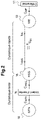
- FIG. 2 is a schematic view showing the dynamics of the elements constituting the powertrain according to the invention.
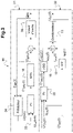
- FIG. 3 is a diagram of the regulation of the powertrain according to the embodiment of the invention.
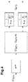
- FIG. 4 is a schematic view of the dynamics of a heat engine of a hybrid motor vehicle according to the invention.
- FIG. 5 is a view representing graphs of results of simulated tests of the method according to the invention.
- a motor vehicle comprises a hybrid powertrain 1.
- the powertrain 1, abbreviated GMP 1 comprises on the one hand an internal combustion engine 18, also called heat engine 18, and two electric machines 10, 16.
- a first electric machine 10 is engaged with the drive members 11 of the motor vehicle.
- This first electrical machine 10 is associated with a first inverter 15 receiving a DC voltage from a DC voltage bus 12.
- This DC voltage bus 12 is voltage regulated by a voltage regulator 13, here an active so-called DC capacitor assembly 13.
- the direct voltage bus 12, also abbreviated DC bus 12 is also connected to a second electrical machine 16, via a second inverter 17.
- This second electric machine 16 is itself connected to the heat engine 18. Thus, the second electric machine 16 is able to convert the energy produced by the heat engine 18 into a voltage that can be transmitted on the DC bus 12.
- the DC bus 12 is also connected to a battery of high-voltage electric accumulators 14, generally with a voltage of substantially 400V, via a controlled protection relay 19.
- DC bus 12 is connected to the on-board network 9 of the motor vehicle, also called the 14 V network via a DC-DC converter 8, abbreviated DC/DC 8.
- only the first electric machine 10 can drive the motor vehicle in motion.
- This first electric machine is supplied either by the battery 14 or by the energy electric transmitted by the second electric machine, by transformation of the energy produced by the heat engine 18.
- the heat engine can be modeled with reference to the figure 4 , by a transfer function comprising a delay e -sh , with s the Laplace variable and h the time value of the delay, multiplied by a first-order filter, determined according to the value of the difference:
- VS MTh ⁇ is the torque control of the heat engine
- C MTh is the torque of the heat engine
- ⁇ is the rotational speed of the heat engine (in rad/s)
- the value h being the time value of the delay of the heat engine 18.
- the system is positioned in a state favorable to the production of power via the following instructions: reference torque for the heat engine 18, HSG 16 and machine electrical 10.
- the technical problem is to find a strategy to achieve a clear demand for traction torque with electric dynamics by limiting the effect of the slow dynamics of the heat engine 18.
- a first regulation part 31 comprises a so-called “predictor” module 34 which estimates the speed of rotation ⁇ (t+h) at time t+h as a function of a target torque value VS ME you ⁇ of the electric machine 10, of the rotational speed ⁇ ( t ), of the target torque value of the thermal engine C ⁇ MTh , of the torque C MTh ( t ) supplied by the thermal engine 18 at time t and of a value ⁇ ref (t+h).
- ⁇ ref (t+h) corresponds to the target speed at which the user request will be produced. This value comes from another strategy which chooses the target speed taking into account in particular the saturations of the HSG 16, of the heat engine 18 and possibly additional parameters.
- a Proportional-Integral regulation 33 is then implemented to regulate the heat engine to the target torque value VS MTh ⁇ you as a function of the estimated anticipated value of the speed of rotation ⁇ ( t +h) of the heat engine 18 and of a value of the reference speed of rotation ⁇ ref ( t + h ) at t + h.
- the value h being the time value of the delay of the heat engine 18.
- a second regulation part 32 makes it possible to regulate the voltage of the bus U DC ( t ) , here according to a non-limiting example of implementation, according to a target voltage VS DC you ⁇ , the bus voltage U DC ( t ) and the target torque of the electric machine VS ME you ⁇ , by another PI 35 regulator.
- J being the inertia obtained by the sum of the flywheel 36 of the heat engine 18 and the inertia of the HSG 16.
- K the simple average between K+ and K- defined previously.
- the fact here of calculating this couple at th makes the prediction calculation simpler.
- the speed regulation loop is open and the heat engine 18 is asked for the maximum torque that it is capable of delivering independently driver's wishes.
- the idea here being to delay the user request C demand in order to allow time for the heat engine to increase in speed and torque, until the moment when the user request can be fulfilled without causing the heat engine 18 to stall.
- This target regime ⁇ ⁇ can be calculated using iterative methods or by searching for a solution as an optimization problem.
- the heat engine receives a maximum torque setpoint VS MThmax ⁇ until time t 2 when the flywheel has stored enough energy to achieve the free torque demand at time t 3 .
- the invention makes it possible to reduce the feeling of this delay and makes it possible to obtain a clear dynamic, close to that of an electric machine 10 connected to the battery. 14.
- the driver thus therefore benefits from the power gain granted by the disconnection of the battery 14 without suffering the consequence of loss of dynamics.
Landscapes
- Engineering & Computer Science (AREA)
- Mechanical Engineering (AREA)
- Transportation (AREA)
- Combustion & Propulsion (AREA)
- Chemical & Material Sciences (AREA)
- Power Engineering (AREA)
- Sustainable Energy (AREA)
- Sustainable Development (AREA)
- Life Sciences & Earth Sciences (AREA)
- Automation & Control Theory (AREA)
- Human Computer Interaction (AREA)
- Health & Medical Sciences (AREA)
- Biomedical Technology (AREA)
- General Health & Medical Sciences (AREA)
- Electric Propulsion And Braking For Vehicles (AREA)
- Control Of Vehicle Engines Or Engines For Specific Uses (AREA)
- Hybrid Electric Vehicles (AREA)
Abstract
- Tant que ladite vitesse de rotation prédite (Ω(t + h)) est inférieure à ladite vitesse de rotation cible (Ω∗), on procède à la commande d'un couple cible


- Lorsque ladite vitesse de rotation prédite (Ω(t + h)) est supérieure ou égale à ladite vitesse de rotation cible (Ω∗), on procède à la commande d'un couple cible

Description
- L'invention a trait au domaine de la commande du groupe motopropulseur d'un véhicule automobile hybride, et plus particulièrement à la commande d'un groupe motopropulseur d'un véhicule automobile hybride fonctionnant dans un mode série à batterie déconnectée.
- Certains véhicules automobiles hybrides comprennent deux machines électriques, un moteur thermique et une batterie électrique haute-tension.
- Pour de tels véhicules, tel que représenté figure la et 1b, il est connu qu'une première machine électrique 10, appelée machine électrique primaire, est connectée aux roues 11, tandis qu'une seconde machine électrique 16 peut être employée, soit de manière connectable aux roues via un arbre de transmission généralement lié au boîtier de vitesses, soit pour assurer une assistance électrique, moteur ou en recharge, à la première machine électrique 10. Une telle architecture est par exemple décrite dans le document
FR3053299 - Dans de tels véhicules hybrides, plusieurs modes d'hybridation sont possibles.
- On entend par mode d'hybridation les différents modes de fonctionnement du véhicule automobile pour assurer la traction et la gestion énergétique en fonction des deux machines électriques et du moteur à combustion interne.
- On connaît deux familles principales d'hybridation : l'hybridation parallèle, dans laquelle les différentes sources d'énergies sont employées en parallèle pour assurer la traction, et l'hybridation série, dans laquelle le véhicule ne fonctionne que par l'énergie électrique, l'énergie thermique ne venant qu'en soutien du moteur électrique.
- L'invention concerne notamment un mode particulier d'une hybridation série, mis en œuvre notamment en cas de défaillance d'une des batteries haute tension, par exemple une batterie 400 volts, afin d'éviter une panne immobilisante. Dans ce mode, la machine électrique 10 assure seule la traction au démarrage ou à basse vitesse.
- Ainsi, lorsque le véhicule est en roulage dans ce mode série particulier, la batterie est déconnectée du système via l'ouverture des relais haute-tension, ici appelés relais HV, ce qui assure la protection vis-à-vis du risque de feu.
- En effet, certaines défaillances batterie impliquent l'interdiction de régénérer la batterie, en utilisant l'énergie produite par les moteurs disponibles ou l'inertie. Cette interdiction induit alors la décharge très rapide de la batterie, et une panne immobilisante pour le conducteur, puisque seule la machine électrique peut assurer le démarrage du véhicule automobile.
- Dans l'hybridation série et parallèle, le moteur à combustion interne est désactivé en dessous d'une certaine vitesse, notamment parce que la typologie de la boîte de vitesse utilisée, généralement une boîte de vitesse automatique non-synchronisée à crabots, empêche son fonctionnement pour démarrer le véhicule. Aussi, en mode hybride parallèle, un arrêt du véhicule induira l'impossibilité de redémarrer, et en mode hybride série, un arrêt du véhicule, avec arrêt du moteur à combustion interne, induira l'impossibilité de redémarrer.
- En outre une décharge du bus haute-tension relié à la batterie haute tension implique, en mode parallèle, l'arrêt de la conversion DCDC pour alimenter le réseau de bord, dit réseau 14V, et déclenche des protections des calculateurs sur ce réseau. Ceci ayant pour conséquence de bloquer le fonctionnement correct du véhicule.
- Ce mode série particulier, utilisé notamment en cas de défaillance batterie, déconnecte la batterie du système de traction, pour éviter de l'endommager, et pour se protéger du risque de feu.
- En outre, ce mode série déconnecte le moteur à combustion interne des roues et le fait fonctionner en régulation de vitesse.
- On procède alors à la régulation de la tension de la capacité de lissage haute tension connectée au bus haute tension, par la machine électrique secondaire, via une structure connue sous le nom de High-voltage Starter Generator, HSG, en français un alterno-démarreur haute-tension, en transformant l'énergie produite par le moteur thermique 18. On parle alors fréquemment de la seconde machine électrique simplement par le terme « HSG 16 ».
- Ce mode série, mis en œuvre dans l'invention permet ainsi de continuer la traction avec la machine électrique principale, connectée aux roues, ainsi que la conversion DCDC, notamment pour alimenter le réseau électrique de bord, à partir de l'énergie disponible sur le bus haute tension dit bus DC, alimenté par la machine électrique secondaire.
- On peut alors contrôler la tension du bus DC par le HSG 16 relié au moteur thermique 18, et ainsi alimenter l'autre machine électrique 10 directement, qui peut alors fournir la puissance voulue à la roue.
- Toutefois dans ce mode série particulier, aussi appelé mode série batterie déconnectée, la réponse à la demande de couple

- En effet, le moteur thermique est environ 50 fois plus lent à répondre à une demande de couple que les machines électriques.
- La dynamique de supervision d'un groupe motopropulseur étant de 100Hz, on peut considérer que les machines électriques répondent immédiatement à toute demande de couple, car leur bande-passante est supérieure à 100Hz.
- Toutefois, le moteur thermique n'a qu'une bande-passante de l'ordre de 4Hz ce qui le fait paraitre très lent par rapport à une machine électrique.
- Dans le mode série batterie déconnectée, comme représenté dans la
figure 2 , l'énergie est apportée par le moteur thermique, convertie en énergie électrique par le HSG 16 puis amenée et convertie à la roue par la machine électrique 10. - La dynamique du véhicule automobile est donc directement liée à la dynamique du moteur thermique 18 comme source d'énergie.
- Le problème est que le conducteur souhaite en toute circonstance disposer des capacités et de la réactivité d'un véhicule hybride électrique, qui doit donc avoir une dynamique « électrique », 50 fois plus rapide à la dynamique d'un moteur thermique.
- Il existe donc le besoin d'apporter une dynamique de véhicule électrique à un système dont la seule source est celle du moteur thermique et qui ne dispose d'aucun stockage d'énergie électrique, la batterie étant déconnectée.
- Aussi l'invention vise à trouver une solution au problème exposé précédemment.
- A cet effet, on propose un procédé de commande d'un groupe motopropulseur hybride d'un véhicule automobile, comprenant une machine électrique primaire d'entraînement du véhicule automobile, connectée via un premier onduleur à un bus de tension continue lissé en tension par un organe d'amortissement passif, le groupe motopropulseur hybride comprenant en outre une machine électrique secondaire apte à recevoir l'énergie produite par un moteur thermique et à la transmettre audit bus de tension continue par l'intermédiaire d'un second onduleur régulant la tension dudit bus de tension continue ; et une batterie d'accumulateurs électrique connectée au bus de tension continue par un relais commandé, pour fournir une tension continue audit bus de tension continue ; le véhicule automobile comprenant un organe de commande du groupe motopropulseur adapté pour mettre en œuvre une étape préalable au cours de laquelle on commande l'ouverture dudit relais commandé de sorte à isoler la batterie du bus de tension continue ; et le procédé étant adapté pour mettre en œuvre les étapes suivantes :
- Une étape de prédiction de ladite vitesse de rotation du moteur thermique, après une durée prédéterminée correspondant au retard en réponse dudit moteur thermique ;
- Une étape de régulation de la vitesse de rotation du moteur thermique en fonction de ladite prédiction de ladite vitesse de rotation du moteur thermique ; et
- lorsqu'une demande de couple supérieure aux capacités en couple instantané du moteur thermique est réalisée par un utilisateur, on procède alors à :
- Une étape de comparaison entre une vitesse de rotation cible du moteur thermique et ladite vitesse de rotation prédite ;
- Tant que ladite vitesse de rotation prédite est inférieure à ladite vitesse de rotation cible, on procède à la commande d'un couple cible de la machine électrique nul et à la commande d'un couple cible du moteur thermique correspondant à la valeur maximale de couple dudit moteur thermique ; et
- Lorsque ladite vitesse de rotation prédite est supérieure ou égale à ladite vitesse de rotation cible, on procède à la commande d'un couple cible de la machine électrique égal au couple demandé par l'utilisateur tandis que le couple du moteur thermique est librement régulé par ladite étape de régulation.
- Ainsi on obtient un procédé permettant de fournir à un véhicule hybride fonctionnant en mode série à batterie déconnectée, une dynamique rapide, proche de celle d'un véhicule tout électrique, lorsqu'un utilisateur effectue une demande franche en couple.
- Avantageusement, on procède par ailleurs à la régulation de la tension du bus continue en fonction du couple cible de la machine électrique, du couple cible de la machine électrique secondaire et d'une valeur de tension cible. Ceci permet de fournir une régulation optimisée pour obtenir la dynamique la plus performante suite à la demande de couple de l'utilisateur.
- En particulier, ladite étape de régulation de la vitesse de rotation du moteur thermique est en outre réalisée en fonction d'une valeur de vitesse de rotation de référence.
- L'invention concerne aussi un organe de commande d'un groupe motopropulseur hybride d'un véhicule automobile, comprenant une machine électrique primaire d'entraînement du véhicule automobile, connectée via un premier onduleur à un bus de tension continue lissé en tension par un organe d'amortissement passif,
- le groupe motopropulseur hybride comprenant en outre une machine électrique secondaire apte à recevoir l'énergie produite par un moteur thermique et à la transmettre audit bus de tension continue par l'intermédiaire d'un second onduleur régulant la tension dudit bus de tension continue ; et une batterie d'accumulateurs électrique connectée au bus de tension continue par un relais commandé, pour fournir une tension continue audit bus de tension continue ;
- ledit organe de commande comprenant des moyens pour mettre en œuvre une étape préalable au cours de laquelle on commande l'ouverture dudit relais commandé de sorte à isoler la batterie du bus de tension continue ; et
- ledit organe de commande comprenant des moyens pour mettre en œuvre les étapes suivantes :
- Une étape de prédiction de ladite vitesse de rotation du moteur thermique, après une durée prédéterminée correspondant au retard en réponse dudit moteur thermique ;
- Une étape de régulation de la vitesse de rotation du moteur thermique en fonction de ladite prédiction de ladite vitesse de rotation du moteur thermique ; et
- lorsqu'une demande de couple supérieure aux capacités en couple instantané du moteur thermique est réalisée par un utilisateur on procède alors à :
- Une étape de comparaison entre une vitesse de rotation cible du moteur thermique et ladite vitesse de rotation prédite ;
- Tant que ladite vitesse de rotation prédite est inférieure à ladite vitesse de rotation cible, on procède à la commande d'un couple cible de la machine électrique nul et à la commande d'un couple cible du moteur thermique correspondant à la valeur maximale de couple dudit moteur thermique ; et
- Lorsque ladite vitesse de rotation prédite est supérieure ou égale à ladite vitesse de rotation cible, on procède à la commande d'un couple cible de la machine électrique égal au couple demandé par l'utilisateur tandis que le couple du moteur thermique est librement régulé par ladite étape de régulation.
- L'invention concerne aussi un véhicule automobile comprenant un groupe motopropulseur hybride d'un véhicule automobile, comprenant une machine électrique primaire d'entraînement du véhicule automobile, connectée via un premier onduleur à un bus de tension continue lissé en tension par un organe d'amortissement passif, le groupe motopropulseur hybride comprenant en outre une machine électrique secondaire apte à recevoir l'énergie produite par un moteur thermique et à la transmettre audit bus de tension continue par l'intermédiaire d'un second onduleur régulant la tension dudit bus de tension continue ; et une batterie d'accumulateurs électrique connectée au bus de tension continue par un relais commandé, pour fournir une tension continue audit bus de tension continue ; le véhicule automobile comprenant un organe de commande du groupe motopropulseur tel que décrit précédemment.
- D'autres particularités et avantages de l'invention ressortiront à la lecture de la description faite ci-après d'un mode de réalisation particulier de l'invention, donné à titre indicatif mais non limitatif, en référence aux dessins annexés sur lesquels :
- [
Fig. 1a ] est une vue schématique d'un groupe motopropulseur d'un véhicule automobile hybride selon l'invention : - [
Fig. 1b ] est une vue d'un schéma électrique du groupe motopropulseur d'un véhicule automobile hybride selon l'invention ; - [
Fig. 2 ] est une vue schématique représentant la dynamique des éléments constituant le groupe motopropulseur selon l'invention ; - [
Fig. 3 ] est un schéma de la régulation du groupe motopropulseur selon le mode de réalisation de l'invention ; - [
Fig. 4 ] est une vue schématique de la dynamique d'un moteur thermique d'un véhicule automobile hybride selon l'invention ; et - [
Fig. 5 ] est une vue représentant des graphiques de résultats d'essais simulés du procédé selon l'invention. - En référence à la
figure 1b , un véhicule automobile comprend un groupe motopropulseur hybride 1. - Le groupe motopropulseur 1, abrégé GMP 1 comprend d'une part un moteur à combustion interne 18, aussi appelé moteur thermique 18, et deux machines électriques 10, 16.
- Dans un mode d'hybridation du GMP 1, mis en œuvre dans l'invention, une première machine électrique 10 est en prise avec les organes 11 d'entraînement du véhicule automobile.
- Cette première machine électrique 10 est associée à un premier onduleur 15 recevant une tension continue d'un bus de tension continue 12.
- Ce bus de tension continue 12 est régulé en tension par un organe de régulation de tension 13, ici un ensemble actif dit de capacité DC 13.
- Le bus de tension continue 12, aussi abrégé bus DC 12 est aussi connecté à une seconde machine électrique 16, par l'intermédiaire d'un second onduleur 17.
- Cette seconde machine électrique 16, est elle-même connectée au moteur thermique 18. Ainsi, la seconde machine électrique 16 est apte à convertir l'énergie produite par le moteur thermique 18 en une tension pouvant être transmise sur le bus DC 12.
- Le bus DC 12 est aussi connecté à une batterie d'accumulateurs électriques haute-tension 14, généralement d'une tension de sensiblement 400V, via un relais 19 de protection commandé.
- De plus le bus DC 12 est connecté au réseau de bord 9 du véhicule automobile, aussi appelé réseau 14 V par l'intermédiaire d'un convertisseur continu-continu 8, abrégé DC/DC 8.
- Selon l'architecture ainsi décrite du mode série, seule la première machine électrique 10 peut entraîner en mouvement le véhicule automobile.
- Cette première machine électrique est alimentée soit par la batterie 14 soit par l'énergie électrique transmise par la seconde machine électrique, par transformation de l'énergie produite par le moteur thermique 18.
- Or comme il a été exposé précédemment, et en référence à la
figure 2 , lorsque l'utilisateur effectue un appel franc de couple dans ce mode série, à batterie isolée, la dynamique lente du moteur thermique 18 crée un retard insatisfaisant pour l'utilisateur, qui attendrait une dynamique rapide comme le permet une machine électrique 10. - Le moteur thermique peut être modélisé en référence à la
figure 4 , par une fonction de transfert comportant un retard e-sh, avec s la variable de Laplace et h la valeur temporelle du retard, multiplié par un filtre de premier ordre, déterminé en fonction de la valeur de la différence : - Si :

- Alors :

- Sinon :

- Dans lesquels :

- CMTh est le couple du moteur thermique
- Ω est la vitesse de rotation du moteur thermique (en rad/s)
- Et les constantes suivantes :


- La valeur h étant la valeur temporelle du retard du moteur thermique 18.
- L'invention vise alors à positionner le système dans un état où l'on peut venir puiser dans deux réserves d'énergie :
- L'inertie du moteur thermique 18 et
- L'énergie de la capacité du bus DC 13 qui a pour but de stabiliser la tension du bus.
- En effet, lors d'un appel franc en couple par un utilisateur du véhicule, alors que le véhicule est en mode série à batterie déconnectée, on dispose de deux degrés de liberté : la vitesse de rotation du volant d'inertie du moteur thermique 18 et la tension de bus UDC.
- Ainsi, on positionne le système dans un état favorable à la réalisation de puissance via les consignes suivantes : couple de référence pour le moteur thermique 18, HSG 16 et machine électrique 10.
- Dès lors, le problème technique est de trouver une stratégie pour réaliser une demande franche de couple de traction avec une dynamique électrique en limitant l'effet de la dynamique lente du moteur thermique 18.
- A cet effet, on met en œuvre des étapes de régulation 32 de la tension du bus continu UDC et de régulation 31 de la vitesse de rotation Ω de la machine thermique 18, en référence à la
figure 3 . - Ces étapes de régulation 31,32 sont représentées
figure 3 sous la forme d'un schéma de régulation 30. - Une première partie de régulation 31 comprend un module dit « prédicteur » 34 qui estime la vitesse de rotation Ω(t + h) à l'instant t+h en fonction d'une valeur de couple cible

- Ωref(t+h) correspond à la vitesse cible à laquelle on va produire la demande utilisateur. Cette valeur provient d'une autre stratégie qui choisit la vitesse cible en prenant en compte notamment les saturations du HSG 16, du moteur thermique 18 et éventuellement des paramètres supplémentaires.
- Une régulation Proportionnelle-Intégrale 33, dit régulation PI 33, est alors mis en œuvre pour réguler la machine thermique à la valeur de couple cible

- En outre une deuxième partie de régulation 32 permet de réguler la tension du bus UDC (t) , ici selon un exemple de mise en œuvre non limitatif, en fonction d'une tension cible


- La régulation générale étant alors acquise par l'équation suivante :

- Dans laquelle :


- J étant l'inertie obtenue par la somme du volant d'inertie 36 du moteur thermique 18 et de l'inertie du HSG 16.
- K la moyenne simple entre K+ et K- définis précédemment.
- Partant de cette régulation, lorsqu'un appel franc de couple est demandé par l'utilisateur du véhicule automobile, le procédé met en œuvre les étapes suivantes :
- Tant que Ω(t + h) < Ω∗ alors le couple cible de la machine électrique reste nul,


- Sinon, le couple demandé à la machine électrique est celui demandé par l'utilisateur :


- Ainsi, tant que la vitesse de rotation prédite Ω(t + h) est inférieure à la vitesse cible Ω∗, la boucle de régulation en vitesse est ouverte et on demande au moteur thermique 18 le couple maximum qu'il est capable de délivrer indépendamment de la volonté du conducteur.
- On va alors surcharger le moteur thermique dont le régime va fortement augmenter. Avec l'augmentation de régime, on va stocker de l'énergie dans le volant d'inertie et arrivé à un certain niveau, on va réaliser l'appel de couple avec la machine électrique 10.
- L'idée étant ici de retarder la demande utilisateur Cdemand afin de laisser le temps au moteur thermique de monter en régime et en couple, jusqu'au moment où on pourra réaliser la demande utilisateur sans faire caler le moteur thermique 18.
- Il existe alors un régime cible Ω∗, dépendant du couple demandé Cdemand et du régime initial, permettant de minimiser le temps de réponse du système (temps d'ouverture de la boucle de régulation).
- Ce régime cible Ω∗ peut être calculé à l'aide de méthodes itératives ou en recherchant une solution comme un problème d'optimisation.
- En référence à la
figure 5 , qui est une représentation d'une simulation effectuée où un appel de couple Cdemand est demandé à l'instant t1=0.1s. - Le moteur thermique reçoit une consigne à couple maximal

- Dans le chronogramme 51, on peut voir une première augmentation du régime Ω du moteur thermique, c'est la phase de surcharge moteur, entre t1 et t3. Ensuite on observe une inflexion après t3, le régime diminuant, c'est la phase de prélèvement d'énergie cinétique.
- Enfin le régime augmente à nouveau, le couple du moteur thermique 18 étant suffisamment élevé pour alimenter en énergie le HSG 16 et la machine électrique 18 qui suit.
- Ainsi, même si l'on ne peut éliminer le retard du moteur thermique 18, l'invention permet de réduire le ressenti de ce retard et permet d'obtenir une dynamique franche, proche de celle d'une machine électrique 10 reliée à la batterie 14.
- Le conducteur bénéficie ainsi donc du gain de puissance accordé par la déconnection de la batterie 14 sans subir la conséquence de perte de dynamique.
Claims (5)
- Procédé de commande d'un groupe motopropulseur hybride (1) d'un véhicule automobile, comprenant une machine électrique primaire (10) d'entraînement du véhicule automobile, connectée via un premier onduleur (15) à un bus de tension continue (12) lissé en tension par un organe d'amortissement passif (13),le groupe motopropulseur hybride (1) comprenant en outre une machine électrique secondaire (16) apte à recevoir l'énergie produite par un moteur thermique (18) et à la transmettre audit bus de tension continue (12) par l'intermédiaire d'un second onduleur (17) régulant la tension dudit bus de tension continue (12) ; et une batterie d'accumulateurs électrique (14) connectée au bus de tension continue (12) par un relais commandé (19), pour fournir une tension continue (VDC) audit bus de tension continue (12) ; le véhicule automobile comprenant un organe de commande du groupe motopropulseur (1) adapté pour mettre en œuvre une étape préalable au cours de laquelle on commande l'ouverture dudit relais commandé (19) de sorte à isoler la batterie (14) du bus de tension continue (12) ; et le procédé étant adapté pour mettre en œuvre les étapes suivantes :- Une étape de prédiction (34) de ladite vitesse de rotation (Ω(t + h)) du moteur thermique (18), après une durée de prédéterminée (h) correspondant au retard en réponse dudit moteur thermique (18) ;- Une étape de régulation (33) de la vitesse de rotation (Ω(t)) du moteur thermique (18) en fonction de ladite prédiction de ladite vitesse de rotation (Ω(t + h)) du moteur thermique (18) ; etlorsqu'une demande de couple (Cdemand) supérieure aux capacités en couple instantané du moteur thermique (18) est réalisée par un utilisateur on procède alors à :- Une étape de comparaison entre une vitesse de rotation cible (Ω∗) du moteur thermique (18) et ladite vitesse de rotation prédite (Ω(t + h)) ;- Tant que ladite vitesse de rotation prédite (Ω(t + h)) est inférieure à ladite vitesse de rotation cible (Ω∗), on procède à la commande d'un couple cible


 - Lorsque ladite vitesse de rotation prédite (Ω(t + h)) est supérieure ou égale à ladite vitesse de rotation cible (Ω∗), on procède à la commande d'un couple cible
- Procédé selon la revendication 1 dans laquelle on procède par ailleurs à la régulation de la tension du bus continue (UDC) en fonction du couple cible


- Procédé selon la revendication 1 ou 2, caractérisé en ce que ladite étape de régulation (33) de la vitesse de rotation Ω(t) du moteur thermique (18) est en outre réalisée en fonction d'une valeur de vitesse de rotation de référence (Ω ref (t + h)).
- Organe de commande d'un groupe motopropulseur hybride (1) d'un véhicule automobile, comprenant une machine électrique primaire (10) d'entraînement du véhicule automobile, connectée via un premier onduleur (15) à un bus de tension continue (12) lissé en tension par un organe d'amortissement passif (13),le groupe motopropulseur hybride (1) comprenant en outre une machine électrique secondaire (16) apte à recevoir l'énergie produite par un moteur thermique (18) et à la transmettre audit bus de tension continue (12) par l'intermédiaire d'un second onduleur (17) régulant la tension dudit bus de tension continue (12) ; et une batterie d'accumulateurs électrique (14) connectée au bus de tension continue (12) par un relais commandé (19), pour fournir une tension continue (VDC) audit bus de tension continue (12) ;ledit organe de commande comprenant des moyens pour mettre en œuvre une étape préalable au cours de laquelle on commande l'ouverture dudit relais commandé (19) de sorte à isoler la batterie (14) du bus de tension continue (12) ; etledit organe de commande comprenant des moyens pour mettre en œuvre les étapes suivantes :- Une étape de prédiction (34) de ladite vitesse de rotation (Ω(t + h)) du moteur thermique (18), après une durée de prédéterminée (h) correspondant au retard en réponse dudit moteur thermique (18) ;- Une étape de régulation (33) de la vitesse de rotation Ω(t) du moteur thermique (18) en fonction de ladite prédiction de ladite vitesse de rotation (Ω(t + h)) du moteur thermique (18) ;De sorte que lorsqu'une demande de couple (Cdemand) supérieure aux capacités en couple instantané du moteur thermique (18) est réalisée par un utilisateur, l'organe de commande met en œuvre :- Une étape de comparaison entre une vitesse de rotation cible (Ω∗) du moteur thermique (18) et ladite vitesse de rotation prédite (Ω(t + h) ;- Tant que ladite vitesse de rotation prédite (Ω(t + h)) est inférieure à ladite vitesse de rotation cible (Ω∗), on procède à la commande d'un couple cible


 - Lorsque ladite vitesse de rotation prédite (Ω(t + h)) est supérieure ou égale à ladite vitesse de rotation cible (Ω∗), on procède à la commande d'un couple cible
- Véhicule automobile comprenant un groupe motopropulseur hybride (1) d'un véhicule automobile, comprenant une machine électrique primaire (10) d'entraînement du véhicule automobile, connectée via un premier onduleur (15) à un bus de tension continue (12) lissé en tension par un organe d'amortissement passif (13),
le groupe motopropulseur hybride (1) comprenant en outre une machine électrique secondaire (16) apte à recevoir l'énergie produite par un moteur thermique (18) et à la transmettre audit bus de tension continue (12) par l'intermédiaire d'un second onduleur (17) régulant la tension dudit bus de tension continue (12) ; et une batterie d'accumulateurs électrique (14) connectée au bus de tension continue (12) par un relais commandé (19), pour fournir une tension continue (VDC) audit bus de tension continue (12) ; le véhicule automobile comprenant un organe de commande du groupe motopropulseur (1) selon la revendication 4.
Applications Claiming Priority (1)
| Application Number | Priority Date | Filing Date | Title |
|---|---|---|---|
| FR2102130A FR3120339B1 (fr) | 2021-03-04 | 2021-03-04 | Commande d’un groupe motopropulseur d’un véhicule automobile hybride fonctionnant dans un mode série à batterie déconnectée |
Publications (2)
| Publication Number | Publication Date |
|---|---|
| EP4052943A1 true EP4052943A1 (fr) | 2022-09-07 |
| EP4052943B1 EP4052943B1 (fr) | 2024-11-06 |
Family
ID=75339959
Family Applications (1)
| Application Number | Title | Priority Date | Filing Date |
|---|---|---|---|
| EP22157313.2A Active EP4052943B1 (fr) | 2021-03-04 | 2022-02-17 | Commande d'un groupe motopropulseur d'un véhicule automobile hybride fonctionnant dans un mode série à batterie déconnectée |
Country Status (2)
| Country | Link |
|---|---|
| EP (1) | EP4052943B1 (fr) |
| FR (1) | FR3120339B1 (fr) |
Families Citing this family (1)
| Publication number | Priority date | Publication date | Assignee | Title |
|---|---|---|---|---|
| FR3152596B1 (fr) | 2023-08-29 | 2025-07-18 | Renault | Procédé de détermination de l’état d’un interrupteur dans un groupe motopropulseur hybride, procédé de commande, dispositif et véhicule correspondants |
Citations (5)
| Publication number | Priority date | Publication date | Assignee | Title |
|---|---|---|---|---|
| FR2783768A1 (fr) * | 1998-09-28 | 2000-03-31 | Renault | Procede de commande d'un vehicule hybride a transmission electrique serie |
| WO2013076566A1 (fr) * | 2011-11-24 | 2013-05-30 | Toyota Jidosha Kabushiki Kaisha | Véhicule et procédé de commande pour véhicule |
| US9834206B1 (en) * | 2017-03-29 | 2017-12-05 | Ford Global Technologies, Llc | Fault-tolerant operation of hybrid electric vehicle |
| FR3053299A1 (fr) | 2016-06-30 | 2018-01-05 | Renault S.A.S | Procede et dispositif de controle de la puissance disponible sur une chaine de traction electrique d'un groupe motopropulseur hybride |
| FR3072056A1 (fr) * | 2017-10-09 | 2019-04-12 | Renault S.A.S | Procede de pilotage d'un groupe motopropulseur hybride electrique |
-
2021
- 2021-03-04 FR FR2102130A patent/FR3120339B1/fr active Active
-
2022
- 2022-02-17 EP EP22157313.2A patent/EP4052943B1/fr active Active
Patent Citations (5)
| Publication number | Priority date | Publication date | Assignee | Title |
|---|---|---|---|---|
| FR2783768A1 (fr) * | 1998-09-28 | 2000-03-31 | Renault | Procede de commande d'un vehicule hybride a transmission electrique serie |
| WO2013076566A1 (fr) * | 2011-11-24 | 2013-05-30 | Toyota Jidosha Kabushiki Kaisha | Véhicule et procédé de commande pour véhicule |
| FR3053299A1 (fr) | 2016-06-30 | 2018-01-05 | Renault S.A.S | Procede et dispositif de controle de la puissance disponible sur une chaine de traction electrique d'un groupe motopropulseur hybride |
| US9834206B1 (en) * | 2017-03-29 | 2017-12-05 | Ford Global Technologies, Llc | Fault-tolerant operation of hybrid electric vehicle |
| FR3072056A1 (fr) * | 2017-10-09 | 2019-04-12 | Renault S.A.S | Procede de pilotage d'un groupe motopropulseur hybride electrique |
Also Published As
| Publication number | Publication date |
|---|---|
| EP4052943B1 (fr) | 2024-11-06 |
| FR3120339B1 (fr) | 2023-03-17 |
| FR3120339A1 (fr) | 2022-09-09 |
Similar Documents
| Publication | Publication Date | Title |
|---|---|---|
| EP2244900B1 (fr) | Procede de couplage d'une machine electrique de traction sur un vehicule hybride et vehicule hybride pour la mise en oeuvre du procede | |
| EP2032405A1 (fr) | Systeme micro-hybride pour vehicule automobile incorporant un module de strategies de pilotage | |
| EP2788221B1 (fr) | Procede de gestion d'un alternateur associe a au moins une batterie d'alimentation et entraine par un moteur thermique | |
| EP4192704B1 (fr) | Procédé de diagnostic de l'ouverture des relais d'une batterie d'un groupe motopropulseur hybride | |
| FR2977220A1 (fr) | Procede de gestion d'un moteur a combustion interne couple a une machine electrique dans un vehicule automobile | |
| EP2906440B1 (fr) | Procede de recuperation d'energie electrique avec lissage de tension sur un reseau electrique embarque | |
| EP3658404B1 (fr) | Procede pour vehicule hybride de controle d'un alternateur de recharge d'une batterie d'un reseau de bord | |
| EP2788228B1 (fr) | Procede de gestion de l'energie electrique d'un vehicule automobile et vehicule automobile mettant en uvre un tel procede | |
| EP4052943B1 (fr) | Commande d'un groupe motopropulseur d'un véhicule automobile hybride fonctionnant dans un mode série à batterie déconnectée | |
| WO2016124831A1 (fr) | Procédé et dispositif d'aide aux décisions de couplage/découplage d'une machine motrice d'un véhicule hybride en fonction du potentiel de récupération de couple d'une autre machine motrice | |
| FR3046976A1 (fr) | Procede de commande de la ligne d'entrainement d'un vehicule automobile comportant un systeme de recuperation-amplification | |
| EP3304682B1 (fr) | Procédé de contrôle d'un ensemble batterie et alternateur pour un moteur de véhicule automobile | |
| FR2931427A1 (fr) | Procede de decouplage d'une machine electrique de traction sur un vehicule hybride et vehicule hybride pour la mise en oeuvre du procede | |
| JP2017177974A (ja) | ハイブリッド車両の制御装置及びハイブリッド車両システム | |
| EP3090910A1 (fr) | Procede de pilotage du moteur thermique d'un vehicule hybride pour une phase de deceleration du vehicule | |
| FR3110127A1 (fr) | Procédé de gestion de l’énergie pour un véhicule automobile hybride | |
| FR2992041A1 (fr) | Procede et dispositif de controle de l'utilisation des moteurs electrique et thermique d'un vehicule hybride, en fonction d'une acceleration demandee par un systeme de controle de vitesse | |
| FR2926043A1 (fr) | Systeme d'arret et de redemarrage automatique du moteur thermique d'un vehicule et procede de pilotage dudit systeme. | |
| EP2622206A2 (fr) | Procede de gestion de l'arret et du redemarrage automatique d'un moteur thermique de vehicule automobile et vehicule automobile correspondant | |
| EP2292459B1 (fr) | Procédé de charge d'un module auxiliaire de stockage d'énergie | |
| EP2113435B1 (fr) | Procédé et dispositif de contrôle d'un stockeur d'énergie pour véhicule hybride | |
| FR3078204A1 (fr) | Gestion de l’energie electrique dans un vehicule automobile hybride | |
| WO2017191387A1 (fr) | Procede de pilotage d'une machine electrique d'un groupe motopropulseur hybride en fonction de la consigne conducteur | |
| FR2993937A1 (fr) | Procede de determination du moyen de demarrage utilise pour demarrer un moteur thermique d'un vehicule automobile hybride | |
| FR3102441A1 (fr) | Procede de pilotage d'un alterno-demarreur a rotor bobine dans une architecture de traction hybride |
Legal Events
| Date | Code | Title | Description |
|---|---|---|---|
| PUAI | Public reference made under article 153(3) epc to a published international application that has entered the european phase |
Free format text: ORIGINAL CODE: 0009012 |
|
| STAA | Information on the status of an ep patent application or granted ep patent |
Free format text: STATUS: THE APPLICATION HAS BEEN PUBLISHED |
|
| AK | Designated contracting states |
Kind code of ref document: A1 Designated state(s): AL AT BE BG CH CY CZ DE DK EE ES FI FR GB GR HR HU IE IS IT LI LT LU LV MC MK MT NL NO PL PT RO RS SE SI SK SM TR |
|
| STAA | Information on the status of an ep patent application or granted ep patent |
Free format text: STATUS: REQUEST FOR EXAMINATION WAS MADE |
|
| 17P | Request for examination filed |
Effective date: 20230209 |
|
| RBV | Designated contracting states (corrected) |
Designated state(s): AL AT BE BG CH CY CZ DE DK EE ES FI FR GB GR HR HU IE IS IT LI LT LU LV MC MK MT NL NO PL PT RO RS SE SI SK SM TR |
|
| P01 | Opt-out of the competence of the unified patent court (upc) registered |
Effective date: 20230608 |
|
| GRAP | Despatch of communication of intention to grant a patent |
Free format text: ORIGINAL CODE: EPIDOSNIGR1 |
|
| STAA | Information on the status of an ep patent application or granted ep patent |
Free format text: STATUS: GRANT OF PATENT IS INTENDED |
|
| RIC1 | Information provided on ipc code assigned before grant |
Ipc: B60W 50/029 20120101ALN20240514BHEP Ipc: B60L 3/12 20060101ALI20240514BHEP Ipc: B60W 10/08 20060101ALI20240514BHEP Ipc: B60W 10/06 20060101ALI20240514BHEP Ipc: B60L 50/61 20190101ALI20240514BHEP Ipc: B60K 6/387 20071001ALI20240514BHEP Ipc: B60K 6/36 20071001ALI20240514BHEP Ipc: B60W 50/00 20060101ALI20240514BHEP Ipc: B60W 20/15 20160101ALI20240514BHEP Ipc: B60W 20/50 20160101ALI20240514BHEP Ipc: B60K 6/547 20071001ALI20240514BHEP Ipc: B60K 6/442 20071001ALI20240514BHEP Ipc: B60K 6/46 20071001AFI20240514BHEP |
|
| INTG | Intention to grant announced |
Effective date: 20240528 |
|
| GRAS | Grant fee paid |
Free format text: ORIGINAL CODE: EPIDOSNIGR3 |
|
| GRAA | (expected) grant |
Free format text: ORIGINAL CODE: 0009210 |
|
| STAA | Information on the status of an ep patent application or granted ep patent |
Free format text: STATUS: THE PATENT HAS BEEN GRANTED |
|
| AK | Designated contracting states |
Kind code of ref document: B1 Designated state(s): AL AT BE BG CH CY CZ DE DK EE ES FI FR GB GR HR HU IE IS IT LI LT LU LV MC MK MT NL NO PL PT RO RS SE SI SK SM TR |
|
| REG | Reference to a national code |
Ref country code: GB Ref legal event code: FG4D Free format text: NOT ENGLISH |
|
| REG | Reference to a national code |
Ref country code: CH Ref legal event code: EP |
|
| REG | Reference to a national code |
Ref country code: DE Ref legal event code: R096 Ref document number: 602022007340 Country of ref document: DE |
|
| REG | Reference to a national code |
Ref country code: IE Ref legal event code: FG4D Free format text: LANGUAGE OF EP DOCUMENT: FRENCH |
|
| REG | Reference to a national code |
Ref country code: LT Ref legal event code: MG9D |
|
| REG | Reference to a national code |
Ref country code: NL Ref legal event code: MP Effective date: 20241106 |
|
| PG25 | Lapsed in a contracting state [announced via postgrant information from national office to epo] |
Ref country code: PT Free format text: LAPSE BECAUSE OF FAILURE TO SUBMIT A TRANSLATION OF THE DESCRIPTION OR TO PAY THE FEE WITHIN THE PRESCRIBED TIME-LIMIT Effective date: 20250306 Ref country code: IS Free format text: LAPSE BECAUSE OF FAILURE TO SUBMIT A TRANSLATION OF THE DESCRIPTION OR TO PAY THE FEE WITHIN THE PRESCRIBED TIME-LIMIT Effective date: 20250306 Ref country code: HR Free format text: LAPSE BECAUSE OF FAILURE TO SUBMIT A TRANSLATION OF THE DESCRIPTION OR TO PAY THE FEE WITHIN THE PRESCRIBED TIME-LIMIT Effective date: 20241106 |
|
| PG25 | Lapsed in a contracting state [announced via postgrant information from national office to epo] |
Ref country code: FI Free format text: LAPSE BECAUSE OF FAILURE TO SUBMIT A TRANSLATION OF THE DESCRIPTION OR TO PAY THE FEE WITHIN THE PRESCRIBED TIME-LIMIT Effective date: 20241106 Ref country code: NL Free format text: LAPSE BECAUSE OF FAILURE TO SUBMIT A TRANSLATION OF THE DESCRIPTION OR TO PAY THE FEE WITHIN THE PRESCRIBED TIME-LIMIT Effective date: 20241106 |
|
| REG | Reference to a national code |
Ref country code: AT Ref legal event code: MK05 Ref document number: 1739019 Country of ref document: AT Kind code of ref document: T Effective date: 20241106 |
|
| PG25 | Lapsed in a contracting state [announced via postgrant information from national office to epo] |
Ref country code: BG Free format text: LAPSE BECAUSE OF FAILURE TO SUBMIT A TRANSLATION OF THE DESCRIPTION OR TO PAY THE FEE WITHIN THE PRESCRIBED TIME-LIMIT Effective date: 20241106 |
|
| PG25 | Lapsed in a contracting state [announced via postgrant information from national office to epo] |
Ref country code: ES Free format text: LAPSE BECAUSE OF FAILURE TO SUBMIT A TRANSLATION OF THE DESCRIPTION OR TO PAY THE FEE WITHIN THE PRESCRIBED TIME-LIMIT Effective date: 20241106 |
|
| PG25 | Lapsed in a contracting state [announced via postgrant information from national office to epo] |
Ref country code: NO Free format text: LAPSE BECAUSE OF FAILURE TO SUBMIT A TRANSLATION OF THE DESCRIPTION OR TO PAY THE FEE WITHIN THE PRESCRIBED TIME-LIMIT Effective date: 20250206 |
|
| PG25 | Lapsed in a contracting state [announced via postgrant information from national office to epo] |
Ref country code: LV Free format text: LAPSE BECAUSE OF FAILURE TO SUBMIT A TRANSLATION OF THE DESCRIPTION OR TO PAY THE FEE WITHIN THE PRESCRIBED TIME-LIMIT Effective date: 20241106 Ref country code: GR Free format text: LAPSE BECAUSE OF FAILURE TO SUBMIT A TRANSLATION OF THE DESCRIPTION OR TO PAY THE FEE WITHIN THE PRESCRIBED TIME-LIMIT Effective date: 20250207 Ref country code: AT Free format text: LAPSE BECAUSE OF FAILURE TO SUBMIT A TRANSLATION OF THE DESCRIPTION OR TO PAY THE FEE WITHIN THE PRESCRIBED TIME-LIMIT Effective date: 20241106 |
|
| PG25 | Lapsed in a contracting state [announced via postgrant information from national office to epo] |
Ref country code: PL Free format text: LAPSE BECAUSE OF FAILURE TO SUBMIT A TRANSLATION OF THE DESCRIPTION OR TO PAY THE FEE WITHIN THE PRESCRIBED TIME-LIMIT Effective date: 20241106 |
|
| PG25 | Lapsed in a contracting state [announced via postgrant information from national office to epo] |
Ref country code: RS Free format text: LAPSE BECAUSE OF FAILURE TO SUBMIT A TRANSLATION OF THE DESCRIPTION OR TO PAY THE FEE WITHIN THE PRESCRIBED TIME-LIMIT Effective date: 20250206 |
|
| PG25 | Lapsed in a contracting state [announced via postgrant information from national office to epo] |
Ref country code: SM Free format text: LAPSE BECAUSE OF FAILURE TO SUBMIT A TRANSLATION OF THE DESCRIPTION OR TO PAY THE FEE WITHIN THE PRESCRIBED TIME-LIMIT Effective date: 20241106 |
|
| PG25 | Lapsed in a contracting state [announced via postgrant information from national office to epo] |
Ref country code: DK Free format text: LAPSE BECAUSE OF FAILURE TO SUBMIT A TRANSLATION OF THE DESCRIPTION OR TO PAY THE FEE WITHIN THE PRESCRIBED TIME-LIMIT Effective date: 20241106 |
|
| PG25 | Lapsed in a contracting state [announced via postgrant information from national office to epo] |
Ref country code: EE Free format text: LAPSE BECAUSE OF FAILURE TO SUBMIT A TRANSLATION OF THE DESCRIPTION OR TO PAY THE FEE WITHIN THE PRESCRIBED TIME-LIMIT Effective date: 20241106 |
|
| PG25 | Lapsed in a contracting state [announced via postgrant information from national office to epo] |
Ref country code: RO Free format text: LAPSE BECAUSE OF FAILURE TO SUBMIT A TRANSLATION OF THE DESCRIPTION OR TO PAY THE FEE WITHIN THE PRESCRIBED TIME-LIMIT Effective date: 20241106 |
|
| PG25 | Lapsed in a contracting state [announced via postgrant information from national office to epo] |
Ref country code: SK Free format text: LAPSE BECAUSE OF FAILURE TO SUBMIT A TRANSLATION OF THE DESCRIPTION OR TO PAY THE FEE WITHIN THE PRESCRIBED TIME-LIMIT Effective date: 20241106 |
|
| PG25 | Lapsed in a contracting state [announced via postgrant information from national office to epo] |
Ref country code: CZ Free format text: LAPSE BECAUSE OF FAILURE TO SUBMIT A TRANSLATION OF THE DESCRIPTION OR TO PAY THE FEE WITHIN THE PRESCRIBED TIME-LIMIT Effective date: 20241106 |
|
| PG25 | Lapsed in a contracting state [announced via postgrant information from national office to epo] |
Ref country code: IT Free format text: LAPSE BECAUSE OF FAILURE TO SUBMIT A TRANSLATION OF THE DESCRIPTION OR TO PAY THE FEE WITHIN THE PRESCRIBED TIME-LIMIT Effective date: 20241106 |
|
| REG | Reference to a national code |
Ref country code: DE Ref legal event code: R097 Ref document number: 602022007340 Country of ref document: DE |
|
| PG25 | Lapsed in a contracting state [announced via postgrant information from national office to epo] |
Ref country code: SE Free format text: LAPSE BECAUSE OF FAILURE TO SUBMIT A TRANSLATION OF THE DESCRIPTION OR TO PAY THE FEE WITHIN THE PRESCRIBED TIME-LIMIT Effective date: 20241106 |
|
| PLBE | No opposition filed within time limit |
Free format text: ORIGINAL CODE: 0009261 |
|
| STAA | Information on the status of an ep patent application or granted ep patent |
Free format text: STATUS: NO OPPOSITION FILED WITHIN TIME LIMIT |
|
| PG25 | Lapsed in a contracting state [announced via postgrant information from national office to epo] |
Ref country code: MC Free format text: LAPSE BECAUSE OF FAILURE TO SUBMIT A TRANSLATION OF THE DESCRIPTION OR TO PAY THE FEE WITHIN THE PRESCRIBED TIME-LIMIT Effective date: 20241106 |
|
| REG | Reference to a national code |
Ref country code: CH Ref legal event code: PL |
|
| 26N | No opposition filed |
Effective date: 20250807 |
|
| PG25 | Lapsed in a contracting state [announced via postgrant information from national office to epo] |
Ref country code: LU Free format text: LAPSE BECAUSE OF NON-PAYMENT OF DUE FEES Effective date: 20250217 |
|
| PG25 | Lapsed in a contracting state [announced via postgrant information from national office to epo] |
Ref country code: CH Free format text: LAPSE BECAUSE OF NON-PAYMENT OF DUE FEES Effective date: 20250228 |
|
| REG | Reference to a national code |
Ref country code: BE Ref legal event code: MM Effective date: 20250228 |
|
| PG25 | Lapsed in a contracting state [announced via postgrant information from national office to epo] |
Ref country code: BE Free format text: LAPSE BECAUSE OF NON-PAYMENT OF DUE FEES Effective date: 20250228 |
|
| PG25 | Lapsed in a contracting state [announced via postgrant information from national office to epo] |
Ref country code: IE Free format text: LAPSE BECAUSE OF NON-PAYMENT OF DUE FEES Effective date: 20250217 |
|
| PGFP | Annual fee paid to national office [announced via postgrant information from national office to epo] |
Ref country code: GB Payment date: 20260220 Year of fee payment: 5 |
|
| PGFP | Annual fee paid to national office [announced via postgrant information from national office to epo] |
Ref country code: DE Payment date: 20260218 Year of fee payment: 5 |
|
| PGFP | Annual fee paid to national office [announced via postgrant information from national office to epo] |
Ref country code: FR Payment date: 20260219 Year of fee payment: 5 |