EP4052606A1 - Ceramic structure, decoration member, suction nozzle, optical member, guide member, brake rotor, daily commodities, and method for manufacturing ceramic structure - Google Patents
Ceramic structure, decoration member, suction nozzle, optical member, guide member, brake rotor, daily commodities, and method for manufacturing ceramic structure Download PDFInfo
- Publication number
- EP4052606A1 EP4052606A1 EP20881177.8A EP20881177A EP4052606A1 EP 4052606 A1 EP4052606 A1 EP 4052606A1 EP 20881177 A EP20881177 A EP 20881177A EP 4052606 A1 EP4052606 A1 EP 4052606A1
- Authority
- EP
- European Patent Office
- Prior art keywords
- recessed portion
- ceramic structure
- recessed
- sintered body
- structure according
- Prior art date
- Legal status (The legal status is an assumption and is not a legal conclusion. Google has not performed a legal analysis and makes no representation as to the accuracy of the status listed.)
- Pending
Links
- 239000000919 ceramic Substances 0.000 title claims abstract description 82
- 238000000034 method Methods 0.000 title claims description 22
- 230000003287 optical effect Effects 0.000 title claims description 18
- 238000004519 manufacturing process Methods 0.000 title claims description 8
- 238000005034 decoration Methods 0.000 title 1
- 230000003746 surface roughness Effects 0.000 claims abstract description 20
- 238000001179 sorption measurement Methods 0.000 claims description 30
- 238000005498 polishing Methods 0.000 claims description 11
- 239000000843 powder Substances 0.000 claims description 11
- 238000000227 grinding Methods 0.000 claims description 7
- 238000010304 firing Methods 0.000 claims description 5
- MCMNRKCIXSYSNV-UHFFFAOYSA-N Zirconium dioxide Chemical compound O=[Zr]=O MCMNRKCIXSYSNV-UHFFFAOYSA-N 0.000 description 14
- 230000002093 peripheral effect Effects 0.000 description 8
- PNEYBMLMFCGWSK-UHFFFAOYSA-N aluminium oxide Inorganic materials [O-2].[O-2].[O-2].[Al+3].[Al+3] PNEYBMLMFCGWSK-UHFFFAOYSA-N 0.000 description 7
- 230000015572 biosynthetic process Effects 0.000 description 7
- 238000007517 polishing process Methods 0.000 description 5
- 239000010432 diamond Substances 0.000 description 4
- 229910003460 diamond Inorganic materials 0.000 description 4
- 238000004873 anchoring Methods 0.000 description 3
- 239000000463 material Substances 0.000 description 3
- UQSXHKLRYXJYBZ-UHFFFAOYSA-N Iron oxide Chemical compound [Fe]=O UQSXHKLRYXJYBZ-UHFFFAOYSA-N 0.000 description 2
- 229910052581 Si3N4 Inorganic materials 0.000 description 2
- 235000013361 beverage Nutrition 0.000 description 2
- 238000004891 communication Methods 0.000 description 2
- 239000008187 granular material Substances 0.000 description 2
- 239000011812 mixed powder Substances 0.000 description 2
- 238000003825 pressing Methods 0.000 description 2
- HBMJWWWQQXIZIP-UHFFFAOYSA-N silicon carbide Chemical compound [Si+]#[C-] HBMJWWWQQXIZIP-UHFFFAOYSA-N 0.000 description 2
- HQVNEWCFYHHQES-UHFFFAOYSA-N silicon nitride Chemical compound N12[Si]34N5[Si]62N3[Si]51N64 HQVNEWCFYHHQES-UHFFFAOYSA-N 0.000 description 2
- 239000002002 slurry Substances 0.000 description 2
- 229910052596 spinel Inorganic materials 0.000 description 2
- MTPVUVINMAGMJL-UHFFFAOYSA-N trimethyl(1,1,2,2,2-pentafluoroethyl)silane Chemical compound C[Si](C)(C)C(F)(F)C(F)(F)F MTPVUVINMAGMJL-UHFFFAOYSA-N 0.000 description 2
- XLYOFNOQVPJJNP-UHFFFAOYSA-N water Substances O XLYOFNOQVPJJNP-UHFFFAOYSA-N 0.000 description 2
- RUDFQVOCFDJEEF-UHFFFAOYSA-N yttrium(III) oxide Inorganic materials [O-2].[O-2].[O-2].[Y+3].[Y+3] RUDFQVOCFDJEEF-UHFFFAOYSA-N 0.000 description 2
- 229910000838 Al alloy Inorganic materials 0.000 description 1
- PIGFYZPCRLYGLF-UHFFFAOYSA-N Aluminum nitride Chemical compound [Al]#N PIGFYZPCRLYGLF-UHFFFAOYSA-N 0.000 description 1
- WQZGKKKJIJFFOK-GASJEMHNSA-N Glucose Natural products OC[C@H]1OC(O)[C@H](O)[C@@H](O)[C@@H]1O WQZGKKKJIJFFOK-GASJEMHNSA-N 0.000 description 1
- 229910026161 MgAl2O4 Inorganic materials 0.000 description 1
- GWEVSGVZZGPLCZ-UHFFFAOYSA-N Titan oxide Chemical compound O=[Ti]=O GWEVSGVZZGPLCZ-UHFFFAOYSA-N 0.000 description 1
- NRTOMJZYCJJWKI-UHFFFAOYSA-N Titanium nitride Chemical compound [Ti]#N NRTOMJZYCJJWKI-UHFFFAOYSA-N 0.000 description 1
- WGLPBDUCMAPZCE-UHFFFAOYSA-N Trioxochromium Chemical compound O=[Cr](=O)=O WGLPBDUCMAPZCE-UHFFFAOYSA-N 0.000 description 1
- 230000002730 additional effect Effects 0.000 description 1
- 239000000654 additive Substances 0.000 description 1
- 230000000996 additive effect Effects 0.000 description 1
- 239000000853 adhesive Substances 0.000 description 1
- 230000001070 adhesive effect Effects 0.000 description 1
- 239000011230 binding agent Substances 0.000 description 1
- 229910000423 chromium oxide Inorganic materials 0.000 description 1
- 238000009694 cold isostatic pressing Methods 0.000 description 1
- 239000002131 composite material Substances 0.000 description 1
- 239000000470 constituent Substances 0.000 description 1
- 229910052593 corundum Inorganic materials 0.000 description 1
- 238000013461 design Methods 0.000 description 1
- 230000000694 effects Effects 0.000 description 1
- 239000008103 glucose Substances 0.000 description 1
- 230000000873 masking effect Effects 0.000 description 1
- 238000005259 measurement Methods 0.000 description 1
- 229910052751 metal Inorganic materials 0.000 description 1
- 239000002184 metal Substances 0.000 description 1
- 239000000203 mixture Substances 0.000 description 1
- 238000012986 modification Methods 0.000 description 1
- 230000004048 modification Effects 0.000 description 1
- 229910052575 non-oxide ceramic Inorganic materials 0.000 description 1
- 239000011225 non-oxide ceramic Substances 0.000 description 1
- 229910052574 oxide ceramic Inorganic materials 0.000 description 1
- 239000011224 oxide ceramic Substances 0.000 description 1
- 238000007788 roughening Methods 0.000 description 1
- 238000004439 roughness measurement Methods 0.000 description 1
- 229910010271 silicon carbide Inorganic materials 0.000 description 1
- 239000002904 solvent Substances 0.000 description 1
- 239000011029 spinel Substances 0.000 description 1
- 238000001694 spray drying Methods 0.000 description 1
- 239000003381 stabilizer Substances 0.000 description 1
- 239000010935 stainless steel Substances 0.000 description 1
- 229910001220 stainless steel Inorganic materials 0.000 description 1
- 239000000126 substance Substances 0.000 description 1
- 210000004243 sweat Anatomy 0.000 description 1
- OGIDPMRJRNCKJF-UHFFFAOYSA-N titanium oxide Inorganic materials [Ti]=O OGIDPMRJRNCKJF-UHFFFAOYSA-N 0.000 description 1
- 229910001845 yogo sapphire Inorganic materials 0.000 description 1
Images







Classifications
-
- H—ELECTRICITY
- H05—ELECTRIC TECHNIQUES NOT OTHERWISE PROVIDED FOR
- H05K—PRINTED CIRCUITS; CASINGS OR CONSTRUCTIONAL DETAILS OF ELECTRIC APPARATUS; MANUFACTURE OF ASSEMBLAGES OF ELECTRICAL COMPONENTS
- H05K13/00—Apparatus or processes specially adapted for manufacturing or adjusting assemblages of electric components
- H05K13/04—Mounting of components, e.g. of leadless components
- H05K13/0404—Pick-and-place heads or apparatus, e.g. with jaws
- H05K13/0408—Incorporating a pick-up tool
- H05K13/0409—Sucking devices
-
- A—HUMAN NECESSITIES
- A47—FURNITURE; DOMESTIC ARTICLES OR APPLIANCES; COFFEE MILLS; SPICE MILLS; SUCTION CLEANERS IN GENERAL
- A47G—HOUSEHOLD OR TABLE EQUIPMENT
- A47G19/00—Table service
-
- A—HUMAN NECESSITIES
- A47—FURNITURE; DOMESTIC ARTICLES OR APPLIANCES; COFFEE MILLS; SPICE MILLS; SUCTION CLEANERS IN GENERAL
- A47G—HOUSEHOLD OR TABLE EQUIPMENT
- A47G19/00—Table service
- A47G19/22—Drinking vessels or saucers used for table service
- A47G19/2205—Drinking glasses or vessels
-
- C—CHEMISTRY; METALLURGY
- C04—CEMENTS; CONCRETE; ARTIFICIAL STONE; CERAMICS; REFRACTORIES
- C04B—LIME, MAGNESIA; SLAG; CEMENTS; COMPOSITIONS THEREOF, e.g. MORTARS, CONCRETE OR LIKE BUILDING MATERIALS; ARTIFICIAL STONE; CERAMICS; REFRACTORIES; TREATMENT OF NATURAL STONE
- C04B35/00—Shaped ceramic products characterised by their composition; Ceramics compositions; Processing powders of inorganic compounds preparatory to the manufacturing of ceramic products
- C04B35/01—Shaped ceramic products characterised by their composition; Ceramics compositions; Processing powders of inorganic compounds preparatory to the manufacturing of ceramic products based on oxide ceramics
- C04B35/10—Shaped ceramic products characterised by their composition; Ceramics compositions; Processing powders of inorganic compounds preparatory to the manufacturing of ceramic products based on oxide ceramics based on aluminium oxide
-
- C—CHEMISTRY; METALLURGY
- C04—CEMENTS; CONCRETE; ARTIFICIAL STONE; CERAMICS; REFRACTORIES
- C04B—LIME, MAGNESIA; SLAG; CEMENTS; COMPOSITIONS THEREOF, e.g. MORTARS, CONCRETE OR LIKE BUILDING MATERIALS; ARTIFICIAL STONE; CERAMICS; REFRACTORIES; TREATMENT OF NATURAL STONE
- C04B35/00—Shaped ceramic products characterised by their composition; Ceramics compositions; Processing powders of inorganic compounds preparatory to the manufacturing of ceramic products
- C04B35/01—Shaped ceramic products characterised by their composition; Ceramics compositions; Processing powders of inorganic compounds preparatory to the manufacturing of ceramic products based on oxide ceramics
- C04B35/48—Shaped ceramic products characterised by their composition; Ceramics compositions; Processing powders of inorganic compounds preparatory to the manufacturing of ceramic products based on oxide ceramics based on zirconium or hafnium oxides, zirconates, zircon or hafnates
-
- C—CHEMISTRY; METALLURGY
- C04—CEMENTS; CONCRETE; ARTIFICIAL STONE; CERAMICS; REFRACTORIES
- C04B—LIME, MAGNESIA; SLAG; CEMENTS; COMPOSITIONS THEREOF, e.g. MORTARS, CONCRETE OR LIKE BUILDING MATERIALS; ARTIFICIAL STONE; CERAMICS; REFRACTORIES; TREATMENT OF NATURAL STONE
- C04B35/00—Shaped ceramic products characterised by their composition; Ceramics compositions; Processing powders of inorganic compounds preparatory to the manufacturing of ceramic products
- C04B35/01—Shaped ceramic products characterised by their composition; Ceramics compositions; Processing powders of inorganic compounds preparatory to the manufacturing of ceramic products based on oxide ceramics
- C04B35/48—Shaped ceramic products characterised by their composition; Ceramics compositions; Processing powders of inorganic compounds preparatory to the manufacturing of ceramic products based on oxide ceramics based on zirconium or hafnium oxides, zirconates, zircon or hafnates
- C04B35/486—Fine ceramics
- C04B35/488—Composites
- C04B35/4885—Composites with aluminium oxide
-
- C—CHEMISTRY; METALLURGY
- C04—CEMENTS; CONCRETE; ARTIFICIAL STONE; CERAMICS; REFRACTORIES
- C04B—LIME, MAGNESIA; SLAG; CEMENTS; COMPOSITIONS THEREOF, e.g. MORTARS, CONCRETE OR LIKE BUILDING MATERIALS; ARTIFICIAL STONE; CERAMICS; REFRACTORIES; TREATMENT OF NATURAL STONE
- C04B35/00—Shaped ceramic products characterised by their composition; Ceramics compositions; Processing powders of inorganic compounds preparatory to the manufacturing of ceramic products
- C04B35/515—Shaped ceramic products characterised by their composition; Ceramics compositions; Processing powders of inorganic compounds preparatory to the manufacturing of ceramic products based on non-oxide ceramics
- C04B35/56—Shaped ceramic products characterised by their composition; Ceramics compositions; Processing powders of inorganic compounds preparatory to the manufacturing of ceramic products based on non-oxide ceramics based on carbides or oxycarbides
- C04B35/565—Shaped ceramic products characterised by their composition; Ceramics compositions; Processing powders of inorganic compounds preparatory to the manufacturing of ceramic products based on non-oxide ceramics based on carbides or oxycarbides based on silicon carbide
-
- C—CHEMISTRY; METALLURGY
- C04—CEMENTS; CONCRETE; ARTIFICIAL STONE; CERAMICS; REFRACTORIES
- C04B—LIME, MAGNESIA; SLAG; CEMENTS; COMPOSITIONS THEREOF, e.g. MORTARS, CONCRETE OR LIKE BUILDING MATERIALS; ARTIFICIAL STONE; CERAMICS; REFRACTORIES; TREATMENT OF NATURAL STONE
- C04B41/00—After-treatment of mortars, concrete, artificial stone or ceramics; Treatment of natural stone
- C04B41/009—After-treatment of mortars, concrete, artificial stone or ceramics; Treatment of natural stone characterised by the material treated
-
- C—CHEMISTRY; METALLURGY
- C04—CEMENTS; CONCRETE; ARTIFICIAL STONE; CERAMICS; REFRACTORIES
- C04B—LIME, MAGNESIA; SLAG; CEMENTS; COMPOSITIONS THEREOF, e.g. MORTARS, CONCRETE OR LIKE BUILDING MATERIALS; ARTIFICIAL STONE; CERAMICS; REFRACTORIES; TREATMENT OF NATURAL STONE
- C04B41/00—After-treatment of mortars, concrete, artificial stone or ceramics; Treatment of natural stone
- C04B41/53—After-treatment of mortars, concrete, artificial stone or ceramics; Treatment of natural stone involving the removal of at least part of the materials of the treated article, e.g. etching, drying of hardened concrete
-
- C—CHEMISTRY; METALLURGY
- C04—CEMENTS; CONCRETE; ARTIFICIAL STONE; CERAMICS; REFRACTORIES
- C04B—LIME, MAGNESIA; SLAG; CEMENTS; COMPOSITIONS THEREOF, e.g. MORTARS, CONCRETE OR LIKE BUILDING MATERIALS; ARTIFICIAL STONE; CERAMICS; REFRACTORIES; TREATMENT OF NATURAL STONE
- C04B41/00—After-treatment of mortars, concrete, artificial stone or ceramics; Treatment of natural stone
- C04B41/80—After-treatment of mortars, concrete, artificial stone or ceramics; Treatment of natural stone of only ceramics
- C04B41/91—After-treatment of mortars, concrete, artificial stone or ceramics; Treatment of natural stone of only ceramics involving the removal of part of the materials of the treated articles, e.g. etching
-
- F—MECHANICAL ENGINEERING; LIGHTING; HEATING; WEAPONS; BLASTING
- F16—ENGINEERING ELEMENTS AND UNITS; GENERAL MEASURES FOR PRODUCING AND MAINTAINING EFFECTIVE FUNCTIONING OF MACHINES OR INSTALLATIONS; THERMAL INSULATION IN GENERAL
- F16D—COUPLINGS FOR TRANSMITTING ROTATION; CLUTCHES; BRAKES
- F16D65/00—Parts or details
- F16D65/02—Braking members; Mounting thereof
- F16D65/12—Discs; Drums for disc brakes
- F16D65/125—Discs; Drums for disc brakes characterised by the material used for the disc body
-
- C—CHEMISTRY; METALLURGY
- C04—CEMENTS; CONCRETE; ARTIFICIAL STONE; CERAMICS; REFRACTORIES
- C04B—LIME, MAGNESIA; SLAG; CEMENTS; COMPOSITIONS THEREOF, e.g. MORTARS, CONCRETE OR LIKE BUILDING MATERIALS; ARTIFICIAL STONE; CERAMICS; REFRACTORIES; TREATMENT OF NATURAL STONE
- C04B2111/00—Mortars, concrete or artificial stone or mixtures to prepare them, characterised by specific function, property or use
- C04B2111/00241—Physical properties of the materials not provided for elsewhere in C04B2111/00
- C04B2111/00362—Friction materials, e.g. used as brake linings, anti-skid materials
-
- C—CHEMISTRY; METALLURGY
- C04—CEMENTS; CONCRETE; ARTIFICIAL STONE; CERAMICS; REFRACTORIES
- C04B—LIME, MAGNESIA; SLAG; CEMENTS; COMPOSITIONS THEREOF, e.g. MORTARS, CONCRETE OR LIKE BUILDING MATERIALS; ARTIFICIAL STONE; CERAMICS; REFRACTORIES; TREATMENT OF NATURAL STONE
- C04B2111/00—Mortars, concrete or artificial stone or mixtures to prepare them, characterised by specific function, property or use
- C04B2111/00474—Uses not provided for elsewhere in C04B2111/00
- C04B2111/00655—Profiles
-
- C—CHEMISTRY; METALLURGY
- C04—CEMENTS; CONCRETE; ARTIFICIAL STONE; CERAMICS; REFRACTORIES
- C04B—LIME, MAGNESIA; SLAG; CEMENTS; COMPOSITIONS THEREOF, e.g. MORTARS, CONCRETE OR LIKE BUILDING MATERIALS; ARTIFICIAL STONE; CERAMICS; REFRACTORIES; TREATMENT OF NATURAL STONE
- C04B2111/00—Mortars, concrete or artificial stone or mixtures to prepare them, characterised by specific function, property or use
- C04B2111/00474—Uses not provided for elsewhere in C04B2111/00
- C04B2111/00965—Uses not provided for elsewhere in C04B2111/00 for household applications, e.g. use of materials as cooking ware
-
- C—CHEMISTRY; METALLURGY
- C04—CEMENTS; CONCRETE; ARTIFICIAL STONE; CERAMICS; REFRACTORIES
- C04B—LIME, MAGNESIA; SLAG; CEMENTS; COMPOSITIONS THEREOF, e.g. MORTARS, CONCRETE OR LIKE BUILDING MATERIALS; ARTIFICIAL STONE; CERAMICS; REFRACTORIES; TREATMENT OF NATURAL STONE
- C04B2235/00—Aspects relating to ceramic starting mixtures or sintered ceramic products
- C04B2235/60—Aspects relating to the preparation, properties or mechanical treatment of green bodies or pre-forms
- C04B2235/612—Machining
-
- C—CHEMISTRY; METALLURGY
- C04—CEMENTS; CONCRETE; ARTIFICIAL STONE; CERAMICS; REFRACTORIES
- C04B—LIME, MAGNESIA; SLAG; CEMENTS; COMPOSITIONS THEREOF, e.g. MORTARS, CONCRETE OR LIKE BUILDING MATERIALS; ARTIFICIAL STONE; CERAMICS; REFRACTORIES; TREATMENT OF NATURAL STONE
- C04B2235/00—Aspects relating to ceramic starting mixtures or sintered ceramic products
- C04B2235/70—Aspects relating to sintered or melt-casted ceramic products
- C04B2235/94—Products characterised by their shape
- C04B2235/945—Products containing grooves, cuts, recesses or protusions
-
- C—CHEMISTRY; METALLURGY
- C04—CEMENTS; CONCRETE; ARTIFICIAL STONE; CERAMICS; REFRACTORIES
- C04B—LIME, MAGNESIA; SLAG; CEMENTS; COMPOSITIONS THEREOF, e.g. MORTARS, CONCRETE OR LIKE BUILDING MATERIALS; ARTIFICIAL STONE; CERAMICS; REFRACTORIES; TREATMENT OF NATURAL STONE
- C04B2235/00—Aspects relating to ceramic starting mixtures or sintered ceramic products
- C04B2235/70—Aspects relating to sintered or melt-casted ceramic products
- C04B2235/96—Properties of ceramic products, e.g. mechanical properties such as strength, toughness, wear resistance
- C04B2235/963—Surface properties, e.g. surface roughness
-
- F—MECHANICAL ENGINEERING; LIGHTING; HEATING; WEAPONS; BLASTING
- F16—ENGINEERING ELEMENTS AND UNITS; GENERAL MEASURES FOR PRODUCING AND MAINTAINING EFFECTIVE FUNCTIONING OF MACHINES OR INSTALLATIONS; THERMAL INSULATION IN GENERAL
- F16D—COUPLINGS FOR TRANSMITTING ROTATION; CLUTCHES; BRAKES
- F16D65/00—Parts or details
- F16D65/02—Braking members; Mounting thereof
- F16D2065/13—Parts or details of discs or drums
- F16D2065/1304—Structure
- F16D2065/1332—Structure external ribs, e.g. for cooling or reinforcement
-
- F—MECHANICAL ENGINEERING; LIGHTING; HEATING; WEAPONS; BLASTING
- F16—ENGINEERING ELEMENTS AND UNITS; GENERAL MEASURES FOR PRODUCING AND MAINTAINING EFFECTIVE FUNCTIONING OF MACHINES OR INSTALLATIONS; THERMAL INSULATION IN GENERAL
- F16D—COUPLINGS FOR TRANSMITTING ROTATION; CLUTCHES; BRAKES
- F16D2200/00—Materials; Production methods therefor
- F16D2200/0082—Production methods therefor
Definitions
- Embodiments of the disclosure relate to a ceramic structure, a decorative member, an adsorption nozzle, an optical member, a guide member, a brake rotor, a daily commodity, and a method of manufacturing the ceramic structure.
- Patent Document 1 there is known a technique of forming a recessed portion such as a groove in a surface of a ceramic structure, and performing various processes by visually recognizing such a recessed portion (refer to Patent Document 1, for example).
- Patent Document 1 JP 2015-191909 A
- a ceramic structure includes a recessed portion formed in a surface of a base formed of ceramic.
- a surface roughness Ra of corner portions of the recessed portion on an opening side is greater than a surface roughness Ra of an outer side of the recessed portion.
- a method of manufacturing a ceramic structure includes firing a powder compact at a predetermined temperature to form a sintered body, grinding a surface of the sintered body, forming a recessed portion in the surface of the sintered body being ground, and barrel polishing the surface of the sintered body in which the recessed portion is formed. Further, the barrel polishing uses media larger than a width of the recessed portion.
- a method of manufacturing a ceramic structure includes forming a recessed portion in a surface of a powder compact, firing the powder compact in which the recessed portion is formed at a predetermined temperature to form a sintered body, and barrel polishing the surface of the sintered body. Further, the barrel polishing uses media larger than a width of the recessed portion.
- a decorative member or the like aesthetically enhanced by forming a recessed portion in a surface of a ceramic structure and using such a recessed portion as a part of a design.
- visibility of the recessed portion is directly related to the aesthetics, and thus it is especially important to improve the visibility of the recessed portion.
- FIG. 1 is a front view of the ring 10 according to the embodiment
- FIG. 2 is a side view of the ring 10 according to the embodiment.
- the ring 10 according to the embodiment is composed of the ceramic structure 1. As illustrated in FIG. 1 , the ring 10 according to the embodiment includes a base 11 having a ring shape, and such a base 11 includes an outer peripheral surface 12 and an inner peripheral surface 13. The base 11 of the ring 10 corresponds to a base 2 of the ceramic structure 1, and the outer peripheral surface 12 of the ring 10 corresponds to a surface 3 of the ceramic structure 1.
- the base 2 (base 11) is formed of ceramic.
- the ceramic constituting the base 2 include oxide ceramics such as alumina (Al 2 O 3 ), zirconia (ZrO 2 ), and spinel (MgAl 2 O 4 ), and non-oxide ceramics such as silicon carbide (SiC), silicon nitride (Si 3 N 4 ), aluminum nitride (AlN), titanium nitride (TiN), and titanium carbide (TiC).
- the main component of the base 2 is preferably zirconia, alumina, zirconia-alumina complex, or silicon carbide. As a result, high mechanical characteristics can be imparted to the ceramic structure 1.
- the term "main component" in the present disclosure refers to 55% by mass or more, given 100% by mass as a total of the constituent components.
- the zirconia-alumina composite being the main component refers to materials in which the total content of zirconia and alumina is 55 mass% or more, and may include not only those with a high zirconia content but also those with a high alumina content.
- a recessed portion 14 having a groove shape is formed in the outer peripheral surface 12 of the ring 10.
- the recessed portion 14 of the ring 10 corresponds to a recessed portion 4 of the ceramic structure 1.
- a plurality (two in the drawing) of the recessed portions 14 having a groove shape and extending in a circumferential direction C of the base 11 are formed in the outer peripheral surface 12 of the ring 10.
- FIG. 3 is an enlarged cross-sectional view of the recessed portion 4 formed in the surface 3 of the ceramic structure 1 according to the embodiment.
- the recessed portion 4 includes a bottom surface 4a, side surfaces 4b, corner portions 4c on a bottom side, and corner portions 4d on an opening side.
- the corner portions 4c on the bottom side are each a corner portion formed in a portion where the bottom surface 4a and the side surface 4b are in contact, and have a curved shape with a predetermined radius of curvature.
- the corner portions 4d on the opening side are each a corner portion formed in a portion where the side surface 4b and a surface 3a of the surface 3 on the outer side of the recessed portion 4 are in contact, and have a curved shape with a predetermined radius of curvature.
- a surface roughness Ra of the corner portions 4d on the opening side is greater than a surface roughness Ra of the surface 3a on the outer side of the recessed portion 4. That is, in the embodiment, the surface of each corner portion 4d on the opening side positioned at an edge of the recessed portion 4 is rougher than the surface 3a on the outer side of the edge of the recessed portion 4.
- this allows the contour of the recessed portion 4 to stand out clearly, improving the visibility of the recessed portion 4 formed in the surface 3 of the ceramic structure 1.
- the surface roughness Ra of the corner portions 4d on the opening side is preferably greater than a surface roughness Ra of an inner portion of the recessed portion 4, such as the bottom surface 4a and the side surfaces 4b of the recessed portion 4, for example.
- this allows the contour of the recessed portion 4 to stand out more clearly, further improving the visibility of the recessed portion 4 formed in the surface 3 of the ceramic structure 1.
- the radius of curvature of the corner portions 4d on the opening side is preferably smaller than the radius of curvature of the corner portions 4c on the bottom side. This allows the contour of the recessed portion 4 to stand out more clearly because the light is clearly reflected by the corner portions 4d on a sharper opening side.
- the visibility of the recessed portion 4 formed in the surface 3 of the ceramic structure 1 can be further improved.
- the surface 3a on the outer side of the recessed portion 4 preferably has a satin finish. This makes it possible to improve the aesthetics of the ring 10 as a decorative member.
- the inner portion of the recessed portion 4 preferably has a mirror finish. This makes it possible to improve the aesthetics of the ring 10 as a decorative member.
- the ring 10 is illustrated as an example of a decorative member, but the decorative member to which the ceramic structure 1 according to the above-described embodiment is applicable is not limited to the ring 10.
- the ceramic structure 1 by applying the ceramic structure 1 to a clock that is a decorative member, it is possible to improve the visibility of the recessed portion 4 formed in the surface 3 of such a clock.
- the object to which the ceramic structure 1 described above is applicable is not limited to a decorative member. Therefore, in the following embodiment, examples are illustrated in which the ceramic structure 1 is applied to various other objects.
- FIG. 4 is a cross-sectional view of the adsorption nozzle assembly 20 according to the embodiment
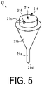
- FIG. 5 is a perspective view of an adsorption nozzle 21 according to the embodiment.
- the adsorption nozzle assembly 20 includes the adsorption nozzle 21 and a flange 22. Further, as illustrated in FIG. 5 , the adsorption nozzle 21 has a tapered shape, and includes a leading end portion 21a, a cone portion 21b, and a mounting portion 21c in this order from the side of the electronic component to be adsorbed.
- the adsorption nozzle 21 includes the ceramic structure 1 according to an embodiment.
- the adsorption nozzle 21 includes a through hole 21e formed from an adsorption surface 21d of the leading end portion 21a through the cone portion 21b and the mounting portion 21c.
- the adsorption surface 21d is a surface that is provided on the leading end portion 21a and comes into contact with the electronic component to be adsorbed.
- the mounting portion 21c is a portion mounted to a receiving portion 22a of the flange 22.
- the flange 22 includes the receiving portion 22a and a communication hole 22b that leads to the through hole 21e of the adsorption nozzle 21, and is a tubular body that encloses the mounting portion 21c of the adsorption nozzle 21.
- the flange 22 is composed of, for example, a metal member of stainless steel, an aluminum alloy, or the like.
- the mounting portion 21c of the adsorption nozzle 21 and the receiving portion 22a of the flange 22 are fitted together to form a single unit. Then, in the adsorption nozzle assembly 20, the communication hole 22b in the flange 22 and the through hole 21e in the adsorption nozzle 21 are connected, and thus function as a suction hole for adsorbing an electronic component or the like.
- a recessed portion 21f having a notched shape is formed in the mounting portion 21c of the adsorption nozzle 21.
- Such a recessed portion 21f is a mark for detecting and aligning a position of the mounting portion 21c when the mounting portion 21c of the adsorption nozzle 21 is fitted to the receiving portion 22a of the flange 22 by a robot.
- a recessed portion 21f corresponds to the recessed portion 4 of the ceramic structure 1 described above. Accordingly, in the adsorption nozzle assembly 20 according to the embodiment, when the mounting portion 21c of the adsorption nozzle 21 is fitted to the receiving portion 22a of the flange 22 by the robot, the mounting portion 21c can be accurately aligned.
- a surface of the mounting portion 21c preferably has a satin finish. This makes it possible to prevent halation when detecting the position of the recessed portion 21f by a camera or the like.
- the mounting portion 21c of the adsorption nozzle 21 when the mounting portion 21c of the adsorption nozzle 21 is fitted to the receiving portion 22a of the flange 22 by the robot, the mounting portion 21c can be more accurately aligned.
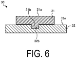
- FIG. 6 is a schematic cross-sectional view of the optical member 30 according to an embodiment.
- the optical member 30 has a predetermined reflectance and is used as: a reference plate that serves as a reference for reflectance in a device that measures a concentration of glucose or other substance; a member that reflects light in an optical measurement device for adjusting errors in rotating machinery; or the like.
- the optical member 30 includes a reflective portion 31 that reflects light, and a support portion 32 that supports such a reflective portion 31.
- the reflective portion 31 includes a reflective surface 31a and a protruding portion 31b.
- the reflective surface 31a is a surface having a predetermined reflectance.
- the protruding portion 31b is provided on a side opposite to the reflective surface 31a, and is a portion supported by the support portion 32.
- the reflective portion 31 is formed of a ceramic (white ceramic, for example) having a high reflectance, for example.
- the support portion 32 includes a main surface 32a and a recessed portion 32b formed in such a main surface 32a.
- the recessed portion 32b is configured to be fitted with the protruding portion 31b of the reflective portion 31. Then, in the optical member 30, the protruding portion 31b of the reflective portion 31 and the recessed portion 32b of the support portion 32 are fitted together and integrated by fixation by an adhesive (not illustrated).
- the support portion 32 is composed of the ceramic structure 1 according to the embodiment.
- the recessed portion 32b corresponds to the recessed portion 4 of the ceramic structure 1. Accordingly, in the optical member 30 according to the embodiment, a position of the recessed portion 32b can be accurately detected, making accurate alignment possible when fitting the protruding portion 31b of the reflective portion 31 to the recessed portion 32b of the support portion 32 by a robot.
- the main surface 32a of the support portion 32 preferably has a satin finish. This makes it possible to reduce the reflectance of the main surface 32a, and thus improve the efficiency of light obtained from the reflective portion 31.
- FIG. 7 is a cross-sectional view of the optical member 30 according to a modified example of the embodiment. As illustrated in FIG. 7 , in the optical member 30, the entire reflective portion 31 may be embedded in the main surface 32a of the support portion 32.
- FIG. 8 is a cross-sectional view of the guide member 40 according to an embodiment.
- the guide member 40 according to the embodiment is used to hold a thread-like member (hereinafter, also referred to as the thread) in a movable state.
- a thread-like member hereinafter, also referred to as the thread
- Such a guide member 40 is composed of the ceramic structure 1 according to the embodiment, and includes a recessed portion 41 having a groove shape. Then, such a recessed portion 41 corresponds to the recessed portion 4 of the ceramic structure 1 described above. Accordingly, in the guide member 40 according to the embodiment, a position of the recessed portion 41 can be accurately detected, making it possible to accurately align the thread when the thread is passed through the recessed portion 41 by a robot.
- an inner portion of the recessed portion 41 preferably has a mirror finish.
- the thread can be easily slid in the inner portion of the recessed portion 41.
- a surface 42 of the guide member 40 preferably has a satin finish.
- a surface area of the surface 42 can be increased, making it possible to more efficiently dissipate heat generated when the thread slides in the inner portion of the recessed portion 41.
- a friction force of the surface 42 is improved, making it possible for a worker to easily handle the guide member 40.
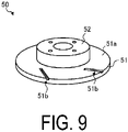
- FIG. 9 is a perspective view of the brake rotor 50 according to an embodiment.
- the brake rotor 50 includes a sliding portion 51 and an anchoring portion 52.
- the sliding portion 51 has a disc shape, and includes a sliding surface 51a and a plurality of recessed portions 51b.
- the sliding surface 51a is a portion that slides with a brake pad (not illustrated) to produce a frictional resistance.
- the plurality of recessed portions 51b are formed in the sliding surface 51a.
- the anchoring portion 52 has a cylindrical shape and is anchored to a wheel (not illustrated).
- the sliding surface 51a and the plurality of recessed portions 51b are provided on both main surfaces of the sliding portion 51 having a disc shape. Then, with the sliding portion 51 interposed between a pair of brake pads, the brake rotor 50 and the pair of brake pads function as a brake.
- the sliding portion 51 includes the ceramic structure 1 according to the embodiment. Then, the recessed portion 51b of the sliding portion 51 corresponds to the recessed portion 4 of the ceramic structure 1. By thus roughening edges of the recessed portions 51b, it is possible to improve the friction force between the sliding surface 51a and the brake pads when the sliding surface 51a slides with the brake pads.
- the performance of the brake on which the brake rotor 50 is mounted can be improved.
- the sliding surface 51a preferably has a satin finish. This can further improve the friction force between the sliding surface 51a and the brake pad when the sliding surface 51a slides with the brake pad, thereby further improving the performance of the brake on which the brake rotor 50 is mounted.
- an inner portion of the recessed portion 51b preferably has a mirror finish.
- brake pad debris accumulated in the inner portion of the recessed portion 51b can be easily discharged.
- the anchoring portion 52 may be integrally formed with the sliding portion 51 by the ceramic structure 1, or may be formed of a material different from that of the sliding portion 51.
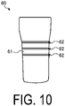
- FIG. 10 is a side view of the tumbler 60 in accordance with an embodiment.
- the tumbler 60 is a daily commodity having a cup shape that opens upward, and is used by a user to consume a beverage by pouring such a beverage into an inner portion from such an opening.
- the tumbler 60 is composed of the ceramic structure 1 according to the embodiment, and includes a holding portion 61 on a side surface.
- the holding portion 61 is a portion held by the user. Further, a plurality (three in the drawing) of recessed portions 62 having a groove shape are formed in the holding portion 61.
- the holding portion 61 is less slippery, making it possible for the user to easily hold the holding portion 61.
- the recessed portion 62 of the holding portion 61 corresponds to the recessed portion 4 of the ceramic structure 1. Edges of the recessed portions 62 are thus roughened, making the holding portion 61 even less slippery. Thus, according to the embodiment, the user can more easily hold the holding portion 61.
- a surface of the holding portion 61 preferably has a satin finish. This makes the holding portion 61 even less slippery, making it even easier for the user to hold the holding portion 61.
- the inner portions of the recessed portions 62 preferably have a mirror finish. As a result, water droplets and the like accumulated in the inner portions of the recessed portions 62 can be easily discharged.
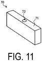
- FIG. 11 is a perspective view of the paperweight 70 according to an embodiment.
- a paperweight 70 is a member placed on top of paper or the like placed on a flat surface such as a desk to prevent such paper from moving, and is composed of the ceramic structure 1 according to the embodiment.
- the paperweight 70 has a substantially rectangular parallelepiped shape, and a recessed portion 72 having a cylindrical shape is formed in an upper surface 71.
- a recessed portion 72 is a portion used for holding a writing implement such as a pen.
- the recessed portion 72 of the upper surface 71 corresponds to the recessed portion 4 of the ceramic structure 1. Edges of the recessed portion 72 are thus roughened, making it less likely that the writing implement will slip. Thus, according to the embodiment, the writing implement can be easily fixed in the paperweight 70.
- a surface of the paperweight 70 preferably has a satin finish. This makes the surface of the paperweight 70 less slippery, making it possible for the user to easily hold the paperweight 70.
- an inner portion of the recessed portion 72 preferably has a mirror finish. This makes the inner portion of the recessed portion 72 more slippery, making it possible to easily remove the writing implement from the recessed portion 72.
- FIG. 12 is a front view of the handle 80 according to an embodiment.
- a handle 80 is a member used when opening or closing a door installed in a room or the like.
- the handle 80 includes a handle portion 81 and a connection portion 82.
- the handle portion 81 is a portion gripped by a user.
- the connection portion 82 is a portion that connects the handle portion 81 and the door (not illustrated).
- a plurality (three in the drawing) of recessed portions 83 having a groove shape are formed in the handle portion 81.
- the handle portion 81 is less slippery, making it possible for the user to easily grip the handle portion 81.
- the handle portion 81 is composed of the ceramic structure 1 according to the embodiment. Then, the recessed portion 83 corresponds to the recessed portion 4 of the ceramic structure 1. Edges of the recessed portions 83 are thus roughened, making the handle portion 81 even less slippery. Thus, according to the embodiment, the user can more easily grip the handle portion 81.
- a surface of the handle portion 81 preferably has a satin finish. This makes the surface of the handle portion 81 less slippery, making it possible for the user to grip the handle portion 81 even more easily.
- inner portions of the recessed portions 83 preferably have a mirror finish. As a result, sweat of the user, debris, and the like accumulated in the inner portions of the recessed portions 83 can be easily discharged.
- the tumbler 60, the paperweight 70, and the handle 80 are illustrated as examples of a daily commodity, but the daily commodity to which the ceramic structure 1 according to the above-described embodiment is applicable is not limited to such examples.
- a mixed powder was prepared with zirconia as the main component, yttria (Y 2 O 3 ) as a stabilizer, and various additive elements (iron oxide, chromium oxide, titanium oxide, and the like) in a predetermined ratio. Then, a predetermined amount of water as a solvent was added to the prepared mixed powder, and the materials were mixed and pulverized in a vibrating mill, a ball mill, or the like, and a slurry was obtained.
- yttria Y 2 O 3
- various additive elements iron oxide, chromium oxide, titanium oxide, and the like
- predetermined amounts of various binders were added to the obtained slurry and the mixture was dried by a spray drying method to obtain granules. Then, the obtained granules were used to obtain a powder compact having a cylindrical shape using a desired pressing method such as, for example, dry pressing, cold isostatic pressing, or the like.
- the obtained powder compact was degreased and subsequently held and fired at a predetermined temperature (from 1300 to 1500°C, for example) for a predetermined time (from 1 to 3 hours, for example) in an air atmosphere to obtain a sintered body 100 (refer to FIG. 13 ) having a ring shape.
- FIG. 13 is an enlarged cross-sectional view schematically illustrating the surface 101 of the sintered body 100 after the grinding process.
- the number of the diamond grindstone used in such a grinding process of the sintered body 100 is relatively low, and thus the surface 101 after the grinding process is relatively rough, as illustrated in FIG. 13 .
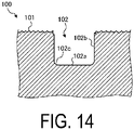
- FIG. 14 is an enlarged cross-sectional view schematically illustrating the surface 101 of the sintered body 100 after formation of the recessed portion 102.
- the number of the diamond grindstone used in such a formation process of the recessed portion 102 is relatively high, and thus an inner portion of the recessed portion 102 (bottom surface 102a, side surfaces 102b, and corner portions 102c on a bottom side of the recessed portion 102, for example) after the recessed portion formation process has a mirror finish, as illustrated in FIG. 14 .
- FIG. 15 is an enlarged cross-sectional view schematically illustrating the surface 101 of the sintered body 100 after barrel polishing.
- media having a width larger than the width of the recessed portion 102 having a groove shape are used.
- the width of the recessed portion 102 is 1 mm
- media having a size of 2 mm or greater are used in the barrel polishing process.
- the sintered body 100 described thus far corresponds to the ceramic structure 1
- the surface 101 corresponds to the surface 3 of the ceramic structure 1
- the recessed portion 102 corresponds to the recessed portion 4 of the ceramic structure 1
- the corner portions 103 on the opening side correspond to the corner portions 4d of the ceramic structure 1 on the opening side.
- the surface roughness Ra of the corner portion 4d on the opening side is greater than the surface roughness Ra on the outer side of the recessed portion 4. This allows the contour of the recessed portion 4 to stand out clearly, thus improving the visibility of the recessed portion 4 formed in the surface 3 of the ceramic structure 1.
- the surface roughness Ra of the corner portion 4d on the opening side is greater than the surface roughness Ra of the inner portion the recessed portion 4. This allows the contour of the recessed portion 4 to stand out more clearly, thus further improving the visibility of the recessed portion 4 formed in the surface 3 of the ceramic structure 1.
- media larger than the width of the recessed portion 102 is used in the barrel polishing process, making it possible to increase the surface roughness Ra only in the corner portions 4d on the opening side, without separately masking the corner portions 4d on the opening side. That is, in the embodiment, the visibility of the recessed portion 4 can be improved by a simple process.
- the sintered body 100 with the recessed portion 102 formed therein is obtained by forming the recessed portion 102 in the powder compact pressed into a ring shape using a predetermined technique and then firing the powder compact at a predetermined temperature for a predetermined time.
- the barrel polishing process is performed on the obtained sintered body 100 using media larger than the width of the recessed portion 102 having a groove shape.
- the ceramic structure 1 similar to the embodiment described above can be obtained.
Landscapes
- Chemical & Material Sciences (AREA)
- Engineering & Computer Science (AREA)
- Ceramic Engineering (AREA)
- Structural Engineering (AREA)
- Organic Chemistry (AREA)
- Materials Engineering (AREA)
- Manufacturing & Machinery (AREA)
- Composite Materials (AREA)
- General Engineering & Computer Science (AREA)
- Mechanical Engineering (AREA)
- Microelectronics & Electronic Packaging (AREA)
- Adornments (AREA)
- Braking Arrangements (AREA)
- Supply And Installment Of Electrical Components (AREA)
- Table Devices Or Equipment (AREA)
- Grinding Of Cylindrical And Plane Surfaces (AREA)
- Grinding And Polishing Of Tertiary Curved Surfaces And Surfaces With Complex Shapes (AREA)
- Finish Polishing, Edge Sharpening, And Grinding By Specific Grinding Devices (AREA)
- Ceramic Products (AREA)
Abstract
Description
- Embodiments of the disclosure relate to a ceramic structure, a decorative member, an adsorption nozzle, an optical member, a guide member, a brake rotor, a daily commodity, and a method of manufacturing the ceramic structure.
- In the related art, there is known a technique of forming a recessed portion such as a groove in a surface of a ceramic structure, and performing various processes by visually recognizing such a recessed portion (refer to
Patent Document 1, for example). - Patent Document 1:
JP 2015-191909 A - A ceramic structure according to an aspect of an embodiment includes a recessed portion formed in a surface of a base formed of ceramic. A surface roughness Ra of corner portions of the recessed portion on an opening side is greater than a surface roughness Ra of an outer side of the recessed portion.
- Further, a method of manufacturing a ceramic structure according to an aspect of an embodiment includes firing a powder compact at a predetermined temperature to form a sintered body, grinding a surface of the sintered body, forming a recessed portion in the surface of the sintered body being ground, and barrel polishing the surface of the sintered body in which the recessed portion is formed. Further, the barrel polishing uses media larger than a width of the recessed portion.
- A method of manufacturing a ceramic structure according to an aspect of the embodiment includes forming a recessed portion in a surface of a powder compact, firing the powder compact in which the recessed portion is formed at a predetermined temperature to form a sintered body, and barrel polishing the surface of the sintered body. Further, the barrel polishing uses media larger than a width of the recessed portion.
-
-
FIG. 1 is a front view of a ring according to an embodiment. -
FIG. 2 is a side view of the ring according to the embodiment. -
FIG. 3 is an enlarged cross-sectional view of a recessed portion formed in a surface of a ceramic structure according to the embodiment. -
FIG. 4 is a cross-sectional view of an adsorption nozzle assembly according to an embodiment. -
FIG. 5 is a perspective view of an adsorption nozzle according to the embodiment. -
FIG. 6 is a cross-sectional view of an optical member according to an embodiment. -
FIG. 7 is a cross-sectional view of the optical member according to a modified example of the embodiment. -
FIG. 8 is a cross-sectional view of a guide member according to an embodiment. -
FIG. 9 is a perspective view of a brake rotor according to an embodiment. -
FIG. 10 is a side view of a tumbler according to an embodiment. -
FIG. 11 is a perspective view of a paperweight according to an embodiment. -
FIG. 12 is a front view of a handle according to an embodiment. -
FIG. 13 is an enlarged cross-sectional view schematically illustrating a surface of a sintered body after a grinding process. -
FIG. 14 is an enlarged cross-sectional view schematically illustrating the surface of the sintered body after formation of the recessed portion. -
FIG. 15 is an enlarged cross-sectional view schematically illustrating the surface of the sintered body after barrel polishing. - Below, embodiments of a ceramic structure, a decorative member, an adsorption nozzle, an optical member, a guide member, a brake rotor, a daily commodity, and a method of manufacturing a ceramic structure disclosed in the present application will be described with reference to the accompanying drawings. Note that this disclosure is not limited by the following embodiments.
- In the related art, there is known a technique of forming a recessed portion such as a groove in a surface of a ceramic structure, and performing various processes by visually recognizing such a recessed portion.
- Further, there is also known a decorative member or the like aesthetically enhanced by forming a recessed portion in a surface of a ceramic structure and using such a recessed portion as a part of a design. In such a decorative member, visibility of the recessed portion is directly related to the aesthetics, and thus it is especially important to improve the visibility of the recessed portion.
- Nevertheless, in the techniques of the related art, there is room for improvement in the visibility of the recessed portion formed in the surface of the ceramic structure.
- Therefore, realization of a ceramic structure that can overcome the problems described above and improve the visibility of the recessed portion formed in the surface is expected.
- First, a configuration of a decorative member to which a
ceramic structure 1 according to an embodiment is applied will be described with reference toFIGS. 1 to 3 . Note that, herein, details of aring 10, which is an example of a decorative member, will be described.FIG. 1 is a front view of thering 10 according to the embodiment, andFIG. 2 is a side view of thering 10 according to the embodiment. - The
ring 10 according to the embodiment is composed of theceramic structure 1. As illustrated inFIG. 1 , thering 10 according to the embodiment includes abase 11 having a ring shape, and such abase 11 includes an outerperipheral surface 12 and an innerperipheral surface 13. Thebase 11 of thering 10 corresponds to abase 2 of theceramic structure 1, and the outerperipheral surface 12 of thering 10 corresponds to asurface 3 of theceramic structure 1. - The base 2 (base 11) is formed of ceramic. Examples of the ceramic constituting the
base 2 include oxide ceramics such as alumina (Al2O3), zirconia (ZrO2), and spinel (MgAl2O4), and non-oxide ceramics such as silicon carbide (SiC), silicon nitride (Si3N4), aluminum nitride (AlN), titanium nitride (TiN), and titanium carbide (TiC). - In the present disclosure, the main component of the
base 2 is preferably zirconia, alumina, zirconia-alumina complex, or silicon carbide. As a result, high mechanical characteristics can be imparted to theceramic structure 1. - Note that the term "main component" in the present disclosure refers to 55% by mass or more, given 100% by mass as a total of the constituent components. Note that the zirconia-alumina composite being the main component refers to materials in which the total content of zirconia and alumina is 55 mass% or more, and may include not only those with a high zirconia content but also those with a high alumina content.
- Further, as illustrated in
FIG. 2 , arecessed portion 14 having a groove shape is formed in the outerperipheral surface 12 of thering 10. Therecessed portion 14 of thering 10 corresponds to arecessed portion 4 of theceramic structure 1. For example, as illustrated inFIG. 2 , a plurality (two in the drawing) of therecessed portions 14 having a groove shape and extending in a circumferential direction C of thebase 11 are formed in the outerperipheral surface 12 of thering 10. -
FIG. 3 is an enlarged cross-sectional view of therecessed portion 4 formed in thesurface 3 of theceramic structure 1 according to the embodiment. As illustrated inFIG. 3 , therecessed portion 4 includes abottom surface 4a,side surfaces 4b,corner portions 4c on a bottom side, andcorner portions 4d on an opening side. - The
corner portions 4c on the bottom side are each a corner portion formed in a portion where thebottom surface 4a and theside surface 4b are in contact, and have a curved shape with a predetermined radius of curvature. Further, thecorner portions 4d on the opening side are each a corner portion formed in a portion where theside surface 4b and asurface 3a of thesurface 3 on the outer side of the recessedportion 4 are in contact, and have a curved shape with a predetermined radius of curvature. - Here, in the embodiment, a surface roughness Ra of the
corner portions 4d on the opening side is greater than a surface roughness Ra of thesurface 3a on the outer side of therecessed portion 4. That is, in the embodiment, the surface of eachcorner portion 4d on the opening side positioned at an edge of therecessed portion 4 is rougher than thesurface 3a on the outer side of the edge of therecessed portion 4. - In this way, when light strikes the
surface 3 in which therecessed portion 4 is formed, a diffused reflection occurs at each edge of the recessed portion 4 (that is,corner portion 4d on the opening side), while a diffused reflection is less likely to occur at thesurface 3a on the outer side of the edge of therecessed portion 4. - Thus, according to the embodiment, this allows the contour of the
recessed portion 4 to stand out clearly, improving the visibility of therecessed portion 4 formed in thesurface 3 of theceramic structure 1. - Further, in the embodiment, the surface roughness Ra of the
corner portions 4d on the opening side is preferably greater than a surface roughness Ra of an inner portion of therecessed portion 4, such as thebottom surface 4a and theside surfaces 4b of therecessed portion 4, for example. - In this way, when light strikes the
surface 3 in which therecessed portion 4 is formed, a diffused reflection occurs at each edge of the recessed portion 4 (that is,corner portions 4d on the opening side), while a diffused reflection is less likely to occur at the inner side of the recessed portion 4 (bottom surface 4a andside surfaces 4b). - Thus, according to the embodiment, this allows the contour of the
recessed portion 4 to stand out more clearly, further improving the visibility of therecessed portion 4 formed in thesurface 3 of theceramic structure 1. - Further, in the embodiment, the radius of curvature of the
corner portions 4d on the opening side is preferably smaller than the radius of curvature of thecorner portions 4c on the bottom side. This allows the contour of the recessedportion 4 to stand out more clearly because the light is clearly reflected by thecorner portions 4d on a sharper opening side. - Thus, according to the embodiment, the visibility of the recessed
portion 4 formed in thesurface 3 of theceramic structure 1 can be further improved. - Further, in the embodiment, the
surface 3a on the outer side of the recessedportion 4 preferably has a satin finish. This makes it possible to improve the aesthetics of thering 10 as a decorative member. - Further, in the embodiment, the inner portion of the recessed
portion 4 preferably has a mirror finish. This makes it possible to improve the aesthetics of thering 10 as a decorative member. - Note that in the embodiment described above, the
ring 10 is illustrated as an example of a decorative member, but the decorative member to which theceramic structure 1 according to the above-described embodiment is applicable is not limited to thering 10. For example, by applying theceramic structure 1 to a clock that is a decorative member, it is possible to improve the visibility of the recessedportion 4 formed in thesurface 3 of such a clock. - Further, the object to which the
ceramic structure 1 described above is applicable is not limited to a decorative member. Therefore, in the following embodiment, examples are illustrated in which theceramic structure 1 is applied to various other objects. - First, a configuration of an
adsorption nozzle assembly 20 to which theceramic structure 1 according to the embodiment is applied will be described with reference toFIGS. 4 and5 .FIG. 4 is a cross-sectional view of theadsorption nozzle assembly 20 according to the embodiment, andFIG. 5 is a perspective view of anadsorption nozzle 21 according to the embodiment. - As illustrated in
FIG. 4 , theadsorption nozzle assembly 20 according to the embodiment includes theadsorption nozzle 21 and aflange 22. Further, as illustrated inFIG. 5 , theadsorption nozzle 21 has a tapered shape, and includes aleading end portion 21a, acone portion 21b, and a mountingportion 21c in this order from the side of the electronic component to be adsorbed. Theadsorption nozzle 21 includes theceramic structure 1 according to an embodiment. - Further, as illustrated in
FIG. 4 , theadsorption nozzle 21 includes a throughhole 21e formed from anadsorption surface 21d of theleading end portion 21a through thecone portion 21b and the mountingportion 21c. Theadsorption surface 21d is a surface that is provided on theleading end portion 21a and comes into contact with the electronic component to be adsorbed. The mountingportion 21c is a portion mounted to a receivingportion 22a of theflange 22. - As illustrated in
FIG. 4 , theflange 22 includes the receivingportion 22a and acommunication hole 22b that leads to the throughhole 21e of theadsorption nozzle 21, and is a tubular body that encloses the mountingportion 21c of theadsorption nozzle 21. Theflange 22 is composed of, for example, a metal member of stainless steel, an aluminum alloy, or the like. - In the
adsorption nozzle assembly 20, the mountingportion 21c of theadsorption nozzle 21 and the receivingportion 22a of theflange 22 are fitted together to form a single unit. Then, in theadsorption nozzle assembly 20, thecommunication hole 22b in theflange 22 and the throughhole 21e in theadsorption nozzle 21 are connected, and thus function as a suction hole for adsorbing an electronic component or the like. - Here, in the
adsorption nozzle assembly 20 according to the embodiment, a recessedportion 21f having a notched shape is formed in the mountingportion 21c of theadsorption nozzle 21. Such a recessedportion 21f is a mark for detecting and aligning a position of the mountingportion 21c when the mountingportion 21c of theadsorption nozzle 21 is fitted to the receivingportion 22a of theflange 22 by a robot. - Then, such a recessed
portion 21f corresponds to the recessedportion 4 of theceramic structure 1 described above. Accordingly, in theadsorption nozzle assembly 20 according to the embodiment, when the mountingportion 21c of theadsorption nozzle 21 is fitted to the receivingportion 22a of theflange 22 by the robot, the mountingportion 21c can be accurately aligned. - Further, in the embodiment, a surface of the mounting
portion 21c preferably has a satin finish. This makes it possible to prevent halation when detecting the position of the recessedportion 21f by a camera or the like. Thus, according to the embodiment, when the mountingportion 21c of theadsorption nozzle 21 is fitted to the receivingportion 22a of theflange 22 by the robot, the mountingportion 21c can be more accurately aligned. - Next, a configuration of an
optical member 30 to which theceramic structure 1 according to the embodiment is applied will be described with reference toFIG. 6. FIG. 6 is a schematic cross-sectional view of theoptical member 30 according to an embodiment. - The
optical member 30 according to the embodiment has a predetermined reflectance and is used as: a reference plate that serves as a reference for reflectance in a device that measures a concentration of glucose or other substance; a member that reflects light in an optical measurement device for adjusting errors in rotating machinery; or the like. - The
optical member 30 according to the embodiment includes areflective portion 31 that reflects light, and asupport portion 32 that supports such areflective portion 31. Thereflective portion 31 includes areflective surface 31a and a protrudingportion 31b. - The
reflective surface 31a is a surface having a predetermined reflectance. The protrudingportion 31b is provided on a side opposite to thereflective surface 31a, and is a portion supported by thesupport portion 32. Thereflective portion 31 is formed of a ceramic (white ceramic, for example) having a high reflectance, for example. - The
support portion 32 includes amain surface 32a and a recessedportion 32b formed in such amain surface 32a. The recessedportion 32b is configured to be fitted with the protrudingportion 31b of thereflective portion 31. Then, in theoptical member 30, the protrudingportion 31b of thereflective portion 31 and the recessedportion 32b of thesupport portion 32 are fitted together and integrated by fixation by an adhesive (not illustrated). - Here, the
support portion 32 is composed of theceramic structure 1 according to the embodiment. Then, the recessedportion 32b corresponds to the recessedportion 4 of theceramic structure 1. Accordingly, in theoptical member 30 according to the embodiment, a position of the recessedportion 32b can be accurately detected, making accurate alignment possible when fitting the protrudingportion 31b of thereflective portion 31 to the recessedportion 32b of thesupport portion 32 by a robot. - Further, in the embodiment, because the surface of the corner portions of the recessed
portion 32b on the opening side are roughened, an anchor effect can be obtained at such corner portions on the opening side. - Further, in the embodiment, the
main surface 32a of thesupport portion 32 preferably has a satin finish. This makes it possible to reduce the reflectance of themain surface 32a, and thus improve the efficiency of light obtained from thereflective portion 31. - Note that the configuration of the
optical member 30 according to the embodiment is not limited to the example ofFIG. 6 .FIG. 7 is a cross-sectional view of theoptical member 30 according to a modified example of the embodiment. As illustrated inFIG. 7 , in theoptical member 30, the entirereflective portion 31 may be embedded in themain surface 32a of thesupport portion 32. - Next, a configuration of a
guide member 40 to which theceramic structure 1 according to the embodiment is applied will be described with reference toFIG. 8. FIG. 8 is a cross-sectional view of theguide member 40 according to an embodiment. Theguide member 40 according to the embodiment is used to hold a thread-like member (hereinafter, also referred to as the thread) in a movable state. - Such a
guide member 40 is composed of theceramic structure 1 according to the embodiment, and includes a recessedportion 41 having a groove shape. Then, such a recessedportion 41 corresponds to the recessedportion 4 of theceramic structure 1 described above. Accordingly, in theguide member 40 according to the embodiment, a position of the recessedportion 41 can be accurately detected, making it possible to accurately align the thread when the thread is passed through the recessedportion 41 by a robot. - Further, in the embodiment, an inner portion of the recessed
portion 41 preferably has a mirror finish. Thus, the thread can be easily slid in the inner portion of the recessedportion 41. - Further, in the embodiment, a
surface 42 of theguide member 40 preferably has a satin finish. Thus, a surface area of thesurface 42 can be increased, making it possible to more efficiently dissipate heat generated when the thread slides in the inner portion of the recessedportion 41. Furthermore, in the embodiment, with thesurface 42 of theguide member 40 being given a satin finish, a friction force of thesurface 42 is improved, making it possible for a worker to easily handle theguide member 40. - Next, a configuration of a
brake rotor 50 to which theceramic structure 1 according to the embodiment is applied will be described with reference toFIG. 9. FIG. 9 is a perspective view of thebrake rotor 50 according to an embodiment. - As illustrated in
FIG. 9 , thebrake rotor 50 according to the embodiment includes a slidingportion 51 and an anchoringportion 52. The slidingportion 51 has a disc shape, and includes a slidingsurface 51a and a plurality of recessedportions 51b. The slidingsurface 51a is a portion that slides with a brake pad (not illustrated) to produce a frictional resistance. The plurality of recessedportions 51b are formed in the slidingsurface 51a. The anchoringportion 52 has a cylindrical shape and is anchored to a wheel (not illustrated). - Note that the sliding
surface 51a and the plurality of recessedportions 51b are provided on both main surfaces of the slidingportion 51 having a disc shape. Then, with the slidingportion 51 interposed between a pair of brake pads, thebrake rotor 50 and the pair of brake pads function as a brake. - Here, the sliding
portion 51 includes theceramic structure 1 according to the embodiment. Then, the recessedportion 51b of the slidingportion 51 corresponds to the recessedportion 4 of theceramic structure 1. By thus roughening edges of the recessedportions 51b, it is possible to improve the friction force between the slidingsurface 51a and the brake pads when the slidingsurface 51a slides with the brake pads. - Thus, according to the embodiment, the performance of the brake on which the
brake rotor 50 is mounted can be improved. - Further, in the embodiment, the sliding
surface 51a preferably has a satin finish. This can further improve the friction force between the slidingsurface 51a and the brake pad when the slidingsurface 51a slides with the brake pad, thereby further improving the performance of the brake on which thebrake rotor 50 is mounted. - Further, in the embodiment, an inner portion of the recessed
portion 51b preferably has a mirror finish. As a result, brake pad debris accumulated in the inner portion of the recessedportion 51b can be easily discharged. Note that the anchoringportion 52 may be integrally formed with the slidingportion 51 by theceramic structure 1, or may be formed of a material different from that of the slidingportion 51. - Next, configurations of various daily commodities to which the
ceramic structure 1 according to the embodiment is applied will be described with reference toFIGS. 10 to 12 . First, details of atumbler 60, which is an example of a daily commodity, will be described.FIG. 10 is a side view of thetumbler 60 in accordance with an embodiment. - The
tumbler 60 according to the embodiment is a daily commodity having a cup shape that opens upward, and is used by a user to consume a beverage by pouring such a beverage into an inner portion from such an opening. - The
tumbler 60 is composed of theceramic structure 1 according to the embodiment, and includes a holdingportion 61 on a side surface. The holdingportion 61 is a portion held by the user. Further, a plurality (three in the drawing) of recessedportions 62 having a groove shape are formed in the holdingportion 61. - With the groove-shaped recessed
portions 62 thus formed in the holdingportion 61, the holdingportion 61 is less slippery, making it possible for the user to easily hold the holdingportion 61. - Here, the recessed
portion 62 of the holdingportion 61 corresponds to the recessedportion 4 of theceramic structure 1. Edges of the recessedportions 62 are thus roughened, making the holdingportion 61 even less slippery. Thus, according to the embodiment, the user can more easily hold the holdingportion 61. - Further, in the embodiment, a surface of the holding
portion 61 preferably has a satin finish. This makes the holdingportion 61 even less slippery, making it even easier for the user to hold the holdingportion 61. - Further, in the embodiment, the inner portions of the recessed
portions 62 preferably have a mirror finish. As a result, water droplets and the like accumulated in the inner portions of the recessedportions 62 can be easily discharged. - Next, details of a
paperweight 70, which is another example of a daily commodity, will be described.FIG. 11 is a perspective view of thepaperweight 70 according to an embodiment. Such apaperweight 70 is a member placed on top of paper or the like placed on a flat surface such as a desk to prevent such paper from moving, and is composed of theceramic structure 1 according to the embodiment. - As illustrated in
FIG. 11 , thepaperweight 70 has a substantially rectangular parallelepiped shape, and a recessedportion 72 having a cylindrical shape is formed in anupper surface 71. Such a recessedportion 72 is a portion used for holding a writing implement such as a pen. - Here, the recessed
portion 72 of theupper surface 71 corresponds to the recessedportion 4 of theceramic structure 1. Edges of the recessedportion 72 are thus roughened, making it less likely that the writing implement will slip. Thus, according to the embodiment, the writing implement can be easily fixed in thepaperweight 70. - Further, in the embodiment, a surface of the
paperweight 70 preferably has a satin finish. This makes the surface of thepaperweight 70 less slippery, making it possible for the user to easily hold thepaperweight 70. - Further, in the embodiment, an inner portion of the recessed
portion 72 preferably has a mirror finish. This makes the inner portion of the recessedportion 72 more slippery, making it possible to easily remove the writing implement from the recessedportion 72. - Next, details of a
handle 80, which is another example of a daily commodity, will be described.FIG. 12 is a front view of thehandle 80 according to an embodiment. Such ahandle 80 is a member used when opening or closing a door installed in a room or the like. - As illustrated in
FIG. 12 , thehandle 80 includes ahandle portion 81 and aconnection portion 82. Thehandle portion 81 is a portion gripped by a user. Theconnection portion 82 is a portion that connects thehandle portion 81 and the door (not illustrated). - Further, a plurality (three in the drawing) of recessed
portions 83 having a groove shape are formed in thehandle portion 81. With the recessedportions 83 having a groove shape thus formed in thehandle portion 81, thehandle portion 81 is less slippery, making it possible for the user to easily grip thehandle portion 81. - Here, the
handle portion 81 is composed of theceramic structure 1 according to the embodiment. Then, the recessedportion 83 corresponds to the recessedportion 4 of theceramic structure 1. Edges of the recessedportions 83 are thus roughened, making thehandle portion 81 even less slippery. Thus, according to the embodiment, the user can more easily grip thehandle portion 81. - Further, in the embodiment, a surface of the
handle portion 81 preferably has a satin finish. This makes the surface of thehandle portion 81 less slippery, making it possible for the user to grip thehandle portion 81 even more easily. - Further, in the embodiment, inner portions of the recessed
portions 83 preferably have a mirror finish. As a result, sweat of the user, debris, and the like accumulated in the inner portions of the recessedportions 83 can be easily discharged. - Note that, in the embodiments described above, the
tumbler 60, thepaperweight 70, and thehandle 80 are illustrated as examples of a daily commodity, but the daily commodity to which theceramic structure 1 according to the above-described embodiment is applicable is not limited to such examples. - In the following, an example of the present disclosure will be specifically described. Note that the ceramic structure 1 (ring 10) with zirconia as the main component is illustrated in the example described below, but the present disclosure is not limited to the example below.
- First, a mixed powder was prepared with zirconia as the main component, yttria (Y2O3) as a stabilizer, and various additive elements (iron oxide, chromium oxide, titanium oxide, and the like) in a predetermined ratio. Then, a predetermined amount of water as a solvent was added to the prepared mixed powder, and the materials were mixed and pulverized in a vibrating mill, a ball mill, or the like, and a slurry was obtained.
- Next, predetermined amounts of various binders were added to the obtained slurry and the mixture was dried by a spray drying method to obtain granules. Then, the obtained granules were used to obtain a powder compact having a cylindrical shape using a desired pressing method such as, for example, dry pressing, cold isostatic pressing, or the like.
- Next, a through hole was formed in the obtained cylindrical powder compact to form a ring shape. Then, the obtained powder compact was degreased and subsequently held and fired at a predetermined temperature (from 1300 to 1500°C, for example) for a predetermined time (from 1 to 3 hours, for example) in an air atmosphere to obtain a sintered body 100 (refer to
FIG. 13 ) having a ring shape. - Next, the obtained sintered
body 100 having a ring shape was put into a predetermined grinder, and a surface 101 (refer toFIG. 13 ), such as an inner peripheral surface or an outer peripheral surface, was ground using a diamond grindstone of a predetermined number.FIG. 13 is an enlarged cross-sectional view schematically illustrating thesurface 101 of thesintered body 100 after the grinding process. - The number of the diamond grindstone used in such a grinding process of the
sintered body 100 is relatively low, and thus thesurface 101 after the grinding process is relatively rough, as illustrated inFIG. 13 . - Next, the ground sintered
body 100 was put into a predetermined grinder and a process of forming a recessed portion 102 (FIG. 14 ) having a groove shape in thesurface 101 using a diamond grindstone of a predetermined number was carried out.FIG. 14 is an enlarged cross-sectional view schematically illustrating thesurface 101 of thesintered body 100 after formation of the recessedportion 102. - The number of the diamond grindstone used in such a formation process of the recessed
portion 102 is relatively high, and thus an inner portion of the recessed portion 102 (bottom surface 102a, side surfaces 102b, andcorner portions 102c on a bottom side of the recessedportion 102, for example) after the recessed portion formation process has a mirror finish, as illustrated inFIG. 14 . - Next, the
sintered body 100 subjected to the recessed portion formation process was put into a predetermined barrel polishing machine and subjected to a barrel polishing process for forming a satin finish on thesurface 101 using media of a predetermined size.FIG. 15 is an enlarged cross-sectional view schematically illustrating thesurface 101 of thesintered body 100 after barrel polishing. - Here, in the embodiment, in such a barrel polishing process, media having a width larger than the width of the recessed
portion 102 having a groove shape are used. For example, in a case in which the width of the recessedportion 102 is 1 mm, media having a size of 2 mm or greater are used in the barrel polishing process. - This allows the media to unproblematically strike the
surface 101 on an outer side of the recessedportion 102, making it possible to treat the surface to the desired satin finish. On the other hand, the media does not readily strikecorner portions 103 of the recessedportion 102 on the opening side, making it difficult to treat the surface to the desired satin finish. - Therefore, as illustrated in
FIG. 15 , at thecorner portions 103 on the opening side, the rough surface state obtained after grinding is relatively maintained. - Lastly, the barrel-polished
sintered body 100 was washed to obtain two ceramic structures 1 (rings 10) of the present disclosure. - The
sintered body 100 described thus far corresponds to theceramic structure 1, thesurface 101 corresponds to thesurface 3 of theceramic structure 1, the recessedportion 102 corresponds to the recessedportion 4 of theceramic structure 1, and thecorner portions 103 on the opening side correspond to thecorner portions 4d of theceramic structure 1 on the opening side. - Then, the surface roughness Ra of the outer side of the recessed
portion 4, thecorner portion 4d of the recessedportion 4 on the opening side, and the inner portion of the recessedportion 4 were respectively measured for the two obtained samples. Such a surface roughness Ra was measured by the surface roughness measurement method specified in JIS B 0601 (1994) using a two-dimensional stylus type roughness measuring instrument. The results are shown in Table 1. -
Table 1 Sample No. Outer portion of recessed portion (µm) Corner portion of recessed portion on opening side (µm) Inner portion of recessed portion (µm) 1 0.22 0.66 0.18 2 0.23 0.60 0.20 - As shown in Table 1, in the
ceramic structure 1 according to the embodiment, it can be seen that the surface roughness Ra of thecorner portion 4d on the opening side is greater than the surface roughness Ra on the outer side of the recessedportion 4. This allows the contour of the recessedportion 4 to stand out clearly, thus improving the visibility of the recessedportion 4 formed in thesurface 3 of theceramic structure 1. - Further, as shown in Table 1, in the
ceramic structure 1 according to the embodiment, it can be seen that the surface roughness Ra of thecorner portion 4d on the opening side is greater than the surface roughness Ra of the inner portion the recessedportion 4. This allows the contour of the recessedportion 4 to stand out more clearly, thus further improving the visibility of the recessedportion 4 formed in thesurface 3 of theceramic structure 1. - Further, in the embodiment, media larger than the width of the recessed
portion 102 is used in the barrel polishing process, making it possible to increase the surface roughness Ra only in thecorner portions 4d on the opening side, without separately masking thecorner portions 4d on the opening side. That is, in the embodiment, the visibility of the recessedportion 4 can be improved by a simple process. - Although embodiments of the present disclosure are described above, the present disclosure is not limited to the embodiments described above, and various modifications can be made without departing from the spirit thereof. For example, in the embodiment described above, a process of forming the recessed
portion 102 was carried out after formation of thesintered body 100, but the process of forming the recessedportion 102 may be carried out before formation of thesintered body 100. - That is, in this example, the
sintered body 100 with the recessedportion 102 formed therein is obtained by forming the recessedportion 102 in the powder compact pressed into a ring shape using a predetermined technique and then firing the powder compact at a predetermined temperature for a predetermined time. - Then, the barrel polishing process is performed on the obtained sintered
body 100 using media larger than the width of the recessedportion 102 having a groove shape. Thus, theceramic structure 1 similar to the embodiment described above can be obtained. - Additional effects and other variations can be easily derived by a person skilled in the art. Thus, a wide variety of aspects of the present disclosure are not limited to the specific details and representative embodiments represented and described above. Accordingly, various changes are possible without departing from the spirit or scope of the general concepts of the disclosure defined by the appended claims and their equivalents.
-
- 1 Ceramic structure
- 2 Base
- 3 Surface
- 4 Recessed portion
- 4a Bottom surface
- 4b Side surface
- 4c Corner portion on bottom side
- 4d Corner portion on opening side
- 10 Ring
- 11 Base
- 12 Outer peripheral surface
- 14 Recessed portion
- 20 Adsorption nozzle assembly
- 21 Adsorption nozzle
- 21c Mounting portion
- 21f Recessed portion
- 22 Flange
- 30 Optical member
- 31 Reflective portion
- 31b Protruding portion
- 32 Support portion
- 32b Recessed portion
- 40 Guide member
- 41 Recessed portion
- 50 Brake rotor
- 51 Sliding portion
- 51a Sliding surface
- 51b Recessed portion
- 60 Tumbler
- 61 Holding portion
- 62 Recessed portion
- 70 Paperweight
- 72 Recessed portion
- 80 Handle
- 83 Recessed portion
Claims (12)
- A ceramic structure comprising:a recessed portion formed in a surface of a base formed of ceramic, whereina surface roughness Ra of corner portions of the recessed portion on an opening side is greater than a surface roughness Ra of an outer side of the recessed portion.
- The ceramic structure according to claim 1, wherein
the surface roughness Ra of the corner portions of the recessed portion on the opening side is greater than a surface roughness Ra of an inner portion of the recessed portion. - The ceramic structure according to claim 1 or 2, whereinthe corner portions of the recessed portion on the opening side and corner portions of the recessed portion on a bottom side each have a curved shape, anda radius of curvature of the corner portions of the recessed portion on the opening side is smaller than a radius of curvature of the corner portions of the recessed portion on the bottom side.
- A decorative member comprising:
the ceramic structure according to any one of claims 1 to 3. - An adsorption nozzle comprising:the ceramic structure according to any one of claims 1 to 3, whereinthe recessed portion is formed for alignment.
- An optical member comprising:a reflective portion comprising a protruding portion; anda support portion comprising the ceramic structure according to any one of claims 1 to 3, whereinthe recessed portion is configured to be fitted to the protruding portion.
- A guide member comprising:the ceramic structure according to any one of claims 1 to 3, whereinthe recessed portion is configured to guide a thread.
- A brake rotor comprising:a sliding portion comprising a ceramic structure according to any one of claims 1 to 3, whereinthe recessed portion is formed in a sliding surface configured to slide with a brake pad to produce a frictional resistance.
- A daily commodity comprising:
the ceramic structure according to any one of claims 1 to 3. - A method of manufacturing a ceramic structure, the method comprising:firing a powder compact at a predetermined temperature to form a sintered body;grinding a surface of the sintered body;forming a recessed portion in the surface of the sintered body being ground; andbarrel polishing the surface of the sintered body in which the recessed portion is formed, whereinthe barrel polishing uses media larger than a width of the recessed portion.
- The method of manufacturing a ceramic structure according to claim 10, wherein
the forming the recessed portion comprises mirror finishing an inner portion of the recessed portion. - A method of manufacturing a ceramic structure, the method comprising:forming a recessed portion in a surface of a powder compact;firing the powder compact in which the recessed portion is formed at a predetermined temperature to form a sintered body; andbarrel polishing the surface of the sintered body, whereinthe barrel polishing uses media larger than a width of the recessed portion.
Applications Claiming Priority (2)
| Application Number | Priority Date | Filing Date | Title |
|---|---|---|---|
| JP2019196409 | 2019-10-29 | ||
| PCT/JP2020/038542 WO2021085106A1 (en) | 2019-10-29 | 2020-10-12 | Ceramic structure, decoration member, suction nozzle, optical member, guide member, brake rotor, daily commodities, and method for manufacturing ceramic structure |
Publications (2)
| Publication Number | Publication Date |
|---|---|
| EP4052606A1 true EP4052606A1 (en) | 2022-09-07 |
| EP4052606A4 EP4052606A4 (en) | 2023-11-22 |
Family
ID=75716183
Family Applications (1)
| Application Number | Title | Priority Date | Filing Date |
|---|---|---|---|
| EP20881177.8A Pending EP4052606A4 (en) | 2019-10-29 | 2020-10-12 | CERAMIC STRUCTURE, DECORATION ELEMENT, SUCTION NOZZLE, OPTICAL ELEMENT, GUIDE ELEMENT, BRAKE ROTOR, DAILY PRODUCTS, AND METHOD FOR MANUFACTURING CERAMIC STRUCTURE |
Country Status (3)
| Country | Link |
|---|---|
| EP (1) | EP4052606A4 (en) |
| JP (1) | JP7404384B2 (en) |
| WO (1) | WO2021085106A1 (en) |
Families Citing this family (1)
| Publication number | Priority date | Publication date | Assignee | Title |
|---|---|---|---|---|
| KR102934956B1 (en) | 2021-12-17 | 2026-03-06 | 현대자동차 주식회사 | System and method for sanding automation |
Family Cites Families (13)
| Publication number | Priority date | Publication date | Assignee | Title |
|---|---|---|---|---|
| JPH05309556A (en) * | 1992-05-07 | 1993-11-22 | Showa Shell Sekiyu Kk | Abrasive material and polishing method for minute parts |
| JPH0812469A (en) * | 1994-06-28 | 1996-01-16 | Kyocera Corp | Mirror finishing method for ceramic members |
| US6449123B1 (en) * | 1999-08-16 | 2002-09-10 | Sumitomo Special Metals Co., Ltd. | Methods for marking a sintered product and for fabricating magnetic head substrate |
| CN101911860B (en) * | 2008-01-18 | 2013-04-10 | 京瓷株式会社 | Vacuum nozzle |
| JP5240722B2 (en) * | 2008-11-27 | 2013-07-17 | 京セラ株式会社 | Ceramic ferrule and its manufacturing method |
| JP5590896B2 (en) | 2010-01-27 | 2014-09-17 | 京セラ株式会社 | Golden ceramic sintered body and decorative member using the same |
| JP5874164B2 (en) * | 2011-01-20 | 2016-03-02 | ソニー株式会社 | Recording medium and recording medium manufacturing method |
| DE102012106304A1 (en) * | 2012-07-13 | 2014-05-22 | Dr. Ing. H.C. F. Porsche Aktiengesellschaft | brake disc |
| JP6039353B2 (en) * | 2012-10-12 | 2016-12-07 | 京セラ株式会社 | Adsorption nozzle assembly |
| JP2014162203A (en) * | 2013-02-27 | 2014-09-08 | Fuji Xerox Co Ltd | Exposure device, image formation device, and method for manufacturing exposure device |
| JP6297879B2 (en) | 2014-03-27 | 2018-03-20 | 京セラ株式会社 | Multi-cavity ceramic substrate and ceramic substrate |
| JP6496094B1 (en) * | 2017-04-27 | 2019-04-03 | 京セラ株式会社 | Decorative parts |
| JP3217730U (en) | 2018-06-15 | 2018-08-30 | 株式会社ジュエリーアイワ | Connecting plate for chain for attaching jewelry |
-
2020
- 2020-10-12 EP EP20881177.8A patent/EP4052606A4/en active Pending
- 2020-10-12 JP JP2021554297A patent/JP7404384B2/en active Active
- 2020-10-12 WO PCT/JP2020/038542 patent/WO2021085106A1/en not_active Ceased
Also Published As
| Publication number | Publication date |
|---|---|
| EP4052606A4 (en) | 2023-11-22 |
| JP7404384B2 (en) | 2023-12-25 |
| JPWO2021085106A1 (en) | 2021-05-06 |
| WO2021085106A1 (en) | 2021-05-06 |
Similar Documents
| Publication | Publication Date | Title |
|---|---|---|
| JP3050183B2 (en) | Ceramic tip clamp type cutting tool | |
| EP4052606A1 (en) | Ceramic structure, decoration member, suction nozzle, optical member, guide member, brake rotor, daily commodities, and method for manufacturing ceramic structure | |
| JPH03295401A (en) | Measuring tape | |
| EP1260611A3 (en) | Cutting tool and tool with holder | |
| CN102042798B (en) | Preparation method of extended resistance test sample and sample grinding and fixing device | |
| EP1116552A3 (en) | Polishing apparatus with thickness measuring means | |
| Elssner et al. | Ceramics and ceramic composites: materialographic preparation | |
| JP6509603B2 (en) | Method of manufacturing pellicle frame | |
| WO2018198983A1 (en) | Decorative component | |
| EP0885691A3 (en) | Polishing apparatus | |
| KR102525393B1 (en) | Setter for firing | |
| US6458444B1 (en) | Ceramic substrate and polishing method thereof | |
| Phatphutthitham et al. | Effect of grinding and polishing protocols on surface roughness, flexural strength, and phase transformation of high-translucent 5 mol% yttria-partially stabilized zirconia | |
| JPH10117099A (en) | Object holder for optical measurement | |
| JP5595519B2 (en) | Ceramic blade | |
| JP3540912B2 (en) | Guide member for fishing line | |
| JP3806964B2 (en) | Method of manufacturing composite ceramic balls for ballpoint pens | |
| JPH1199426A (en) | Electronic component suction nozzle | |
| JPH10217089A (en) | Polishing height position setting method in polishing apparatus | |
| EP0819929B1 (en) | Carrier and its use in the preparation of samples for spectroscopy | |
| CN208557108U (en) | The processing tool of gauge block | |
| JPH0632888B2 (en) | Chamfering machine and ceramic chamfering method using the same | |
| JPS614949A (en) | Discriminating method of indentation cracking in ceramics | |
| JPH0618456A (en) | Method for detecting material surface defects | |
| KR200299223Y1 (en) | Ceramic nozzle tip using vacuum absorption |
Legal Events
| Date | Code | Title | Description |
|---|---|---|---|
| STAA | Information on the status of an ep patent application or granted ep patent |
Free format text: STATUS: THE INTERNATIONAL PUBLICATION HAS BEEN MADE |
|
| PUAI | Public reference made under article 153(3) epc to a published international application that has entered the european phase |
Free format text: ORIGINAL CODE: 0009012 |
|
| STAA | Information on the status of an ep patent application or granted ep patent |
Free format text: STATUS: REQUEST FOR EXAMINATION WAS MADE |
|
| 17P | Request for examination filed |
Effective date: 20220429 |
|
| AK | Designated contracting states |
Kind code of ref document: A1 Designated state(s): AL AT BE BG CH CY CZ DE DK EE ES FI FR GB GR HR HU IE IS IT LI LT LU LV MC MK MT NL NO PL PT RO RS SE SI SK SM TR |
|
| DAV | Request for validation of the european patent (deleted) | ||
| DAX | Request for extension of the european patent (deleted) | ||
| P01 | Opt-out of the competence of the unified patent court (upc) registered |
Effective date: 20230505 |
|
| REG | Reference to a national code |
Ref country code: DE Ref legal event code: R079 Free format text: PREVIOUS MAIN CLASS: A44C0009000000 Ipc: C04B0041530000 |
|
| A4 | Supplementary search report drawn up and despatched |
Effective date: 20231025 |
|
| RIC1 | Information provided on ipc code assigned before grant |
Ipc: F16D 65/02 20060101ALN20231019BHEP Ipc: C04B 111/00 20060101ALN20231019BHEP Ipc: A47G 19/22 20060101ALI20231019BHEP Ipc: C04B 35/565 20060101ALI20231019BHEP Ipc: C04B 35/488 20060101ALI20231019BHEP Ipc: C04B 35/48 20060101ALI20231019BHEP Ipc: C04B 35/10 20060101ALI20231019BHEP Ipc: H05K 13/04 20060101ALI20231019BHEP Ipc: F16D 65/12 20060101ALI20231019BHEP Ipc: A47G 19/00 20060101ALI20231019BHEP Ipc: C04B 41/91 20060101ALI20231019BHEP Ipc: C04B 41/00 20060101ALI20231019BHEP Ipc: C04B 41/53 20060101AFI20231019BHEP |