EP4051453B1 - Method, power tool and two-speed gear assembly for a power tool - Google Patents
Method, power tool and two-speed gear assembly for a power tool Download PDFInfo
- Publication number
- EP4051453B1 EP4051453B1 EP20793613.9A EP20793613A EP4051453B1 EP 4051453 B1 EP4051453 B1 EP 4051453B1 EP 20793613 A EP20793613 A EP 20793613A EP 4051453 B1 EP4051453 B1 EP 4051453B1
- Authority
- EP
- European Patent Office
- Prior art keywords
- coupling sleeve
- power tool
- planetary gear
- sleeve
- torque
- Prior art date
- Legal status (The legal status is an assumption and is not a legal conclusion. Google has not performed a legal analysis and makes no representation as to the accuracy of the status listed.)
- Active
Links
Images
Classifications
-
- B—PERFORMING OPERATIONS; TRANSPORTING
- B25—HAND TOOLS; PORTABLE POWER-DRIVEN TOOLS; MANIPULATORS
- B25B—TOOLS OR BENCH DEVICES NOT OTHERWISE PROVIDED FOR, FOR FASTENING, CONNECTING, DISENGAGING, OR HOLDING
- B25B21/00—Portable power-driven screw or nut setting or loosening tools; Attachments for drilling apparatus serving the same purpose
- B25B21/008—Portable power-driven screw or nut setting or loosening tools; Attachments for drilling apparatus serving the same purpose with automatic change-over from high speed-low torque mode to low speed-high torque mode
-
- B—PERFORMING OPERATIONS; TRANSPORTING
- B25—HAND TOOLS; PORTABLE POWER-DRIVEN TOOLS; MANIPULATORS
- B25F—COMBINATION OR MULTI-PURPOSE TOOLS NOT OTHERWISE PROVIDED FOR; DETAILS OR COMPONENTS OF PORTABLE POWER-DRIVEN TOOLS NOT PARTICULARLY RELATED TO THE OPERATIONS PERFORMED AND NOT OTHERWISE PROVIDED FOR
- B25F5/00—Details or components of portable power-driven tools not particularly related to the operations performed and not otherwise provided for
- B25F5/001—Gearings, speed selectors, clutches or the like specially adapted for rotary tools
-
- F—MECHANICAL ENGINEERING; LIGHTING; HEATING; WEAPONS; BLASTING
- F16—ENGINEERING ELEMENTS AND UNITS; GENERAL MEASURES FOR PRODUCING AND MAINTAINING EFFECTIVE FUNCTIONING OF MACHINES OR INSTALLATIONS; THERMAL INSULATION IN GENERAL
- F16H—GEARING
- F16H3/00—Toothed gearings for conveying rotary motion with variable gear ratio or for reversing rotary motion
- F16H3/44—Toothed gearings for conveying rotary motion with variable gear ratio or for reversing rotary motion using gears having orbital motion
-
- F—MECHANICAL ENGINEERING; LIGHTING; HEATING; WEAPONS; BLASTING
- F16—ENGINEERING ELEMENTS AND UNITS; GENERAL MEASURES FOR PRODUCING AND MAINTAINING EFFECTIVE FUNCTIONING OF MACHINES OR INSTALLATIONS; THERMAL INSULATION IN GENERAL
- F16H—GEARING
- F16H61/00—Control functions within control units of change-speed- or reversing-gearings for conveying rotary motion ; Control of exclusively fluid gearing, friction gearing, gearings with endless flexible members or other particular types of gearing
- F16H61/02—Control functions within control units of change-speed- or reversing-gearings for conveying rotary motion ; Control of exclusively fluid gearing, friction gearing, gearings with endless flexible members or other particular types of gearing characterised by the signals used
-
- F—MECHANICAL ENGINEERING; LIGHTING; HEATING; WEAPONS; BLASTING
- F16—ENGINEERING ELEMENTS AND UNITS; GENERAL MEASURES FOR PRODUCING AND MAINTAINING EFFECTIVE FUNCTIONING OF MACHINES OR INSTALLATIONS; THERMAL INSULATION IN GENERAL
- F16H—GEARING
- F16H63/00—Control outputs from the control unit to change-speed- or reversing-gearings for conveying rotary motion or to other devices than the final output mechanism
- F16H63/02—Final output mechanisms therefor; Actuating means for the final output mechanisms
- F16H63/30—Constructional features of the final output mechanisms
-
- F—MECHANICAL ENGINEERING; LIGHTING; HEATING; WEAPONS; BLASTING
- F16—ENGINEERING ELEMENTS AND UNITS; GENERAL MEASURES FOR PRODUCING AND MAINTAINING EFFECTIVE FUNCTIONING OF MACHINES OR INSTALLATIONS; THERMAL INSULATION IN GENERAL
- F16H—GEARING
- F16H63/00—Control outputs from the control unit to change-speed- or reversing-gearings for conveying rotary motion or to other devices than the final output mechanism
- F16H63/02—Final output mechanisms therefor; Actuating means for the final output mechanisms
- F16H63/30—Constructional features of the final output mechanisms
- F16H63/304—Constructional features of the final output mechanisms the final output mechanisms comprising elements moved by electrical or magnetic force
- F16H2063/3053—Constructional features of the final output mechanisms the final output mechanisms comprising elements moved by electrical or magnetic force using linear motors
Definitions
- the present invention generally relates to power tool, more particularly to a power tool comprising a two-speed gear assembly.
- Power tools subjected to these types of varying requirements are however known to, in order to be able to provide the desired torque levels, include one or more transmissions such as for example one or more planetary gear steps connected in series.
- a power tool having an improved two speed transmission.
- a transmission providing improved possibilities for controlling the gear shifting.
- a gear unit for a tightening tool a power tool comprising such a gear unit and a method for controlling such a power tool as defined in the independent claims is provided. Preferred embodiments are defined in the dependent claims.
- a power tool comprising a two-speed power transmission
- the tool comprising a housing, an input shaft, an output shaft and a two-speed power transmission
- the two-speed power transmission comprising a planetary gear and a two speed gear shift assembly for directing torque through the planetary gear in a high torque/low speed drive mode or past the planetary gear in a low torque/high speed drive mode.
- the gear shift assembly comprising a driving member drivingly connected to the input shaft, a driven member drivingly connected to the output shaft, an axially movable coupling sleeve arranged to intercouple in a first position the driving member and the driven member and to intercouple in a second position the planetary gear and the driven member, and a linear actuator arranged to displace an axially movable coupling sleeve between the first and second position, wherein the linear actuator comprises a linearly movable push bar arranged to displace the coupling sleeve between the first and second position.
- the two-speed transmission provides an inventive solution to the concerns described above by means of a design incorporating a gear shift mechanism directing torque through a planetary gear step in a high torque/low speed drive mode or past the planetary gear in a low torque/high speed drive mode, where improved possibilities to accurately control the gear shifting is provided by means of the utilization of a coupling sleeve displaced by a linear actuator.
- the linear actuator is arranged to displace the coupling sleeve
- the engagement in the respective modes of operation may be determined based on the position of the linear actuator.
- the design therefore cleverly provides a two-speed power transmission capable of providing precise and accurate control of the gear shifting.
- the power tool further comprises a motor and means for monitoring the torque delivered by the tool.
- the means for monitoring a torque delivered by the tool may comprise for example a sensor such as a torque transducer.
- Other examples include circuitry adapted to monitor the motor current or other internally provided data related to the performance of the motor.
- the power tool may also form part of a system comprising the power tool and an external control unit operative to control the power tool.
- the motor is an electric motor.
- the tool may for example be an electrical hand-held power tool chosen from the group comprising a screw driver, a nut runner, a drill and a grinder. The skilled person however realizes that only slight modification of the structure would be required for use with a stationary or fixtured tools.
- the power tool may be a battery powered tool.
- the power tool is a tool providing a higher tightening torque, for example in the range 2400-8000 Nm.
- the gear assembly further comprises a coupling assembly arranged between the coupling sleeve and the linear actuator, the coupling assembly comprising a first element rotationally coupled to the sleeve and a second element translationally coupled to the push bar, wherein a rotation of the first element is independent of a rotation of the second element and wherein the second element is arranged to push the first element in an axial direction.
- the rotation of the sleeve and hence the motor does not affect the linear actuator and the adjustment of the axial position of the sleeve may take place independently of the rotation.
- the second element may form part of the push bar.
- the gear assembly further comprises a coupling assembly arranged to couple (i.e. link or connect) the coupling sleeve and the linear actuator, the coupling assembly comprising a first element rotationally coupled to the sleeve and a second element translationally coupled to the push bar, wherein a rotation of the first element is independent of a rotation of the second element and wherein the second element is arranged to push the first element in an axial direction.
- the rotation of the sleeve and hence the motor does not affect the linear actuator and the adjustment of the axial position of the sleeve may take place independently of the rotation.
- the second element may form part of the push bar and/or be formed by the push bar.
- the coupling sleeve is concentrically arranged with respect to the planetary gear, wherein the second element is adapted to engage the first element in a position lying in a center of the sleeve.
- the first element is a ball arranged at least partly in the sleeve, wherein the second element arranged to push the ball is formed by the push bar.
- the end of the push bar may bear against the rotating bar to displace the sleeve.
- the ball may for example be arranged at the end of the sleeve facing the linear actuator, for example by means of a press fit or similar.
- the gear assembly further comprises a coupling assembly arranged between the coupling sleeve and the linear actuator, the coupling assembly comprising a first element rotationally coupled to the sleeve, wherein a rotation of the first element is independent of a rotation of the push bar and wherein the push bar is arranged to push the first element in an axial direction.
- the rotation of the sleeve and hence the motor does not affect the linear actuator and the adjustment of the axial position of the sleeve may take place independently of the rotation.
- the coupling sleeve is concentrically arranged with respect to the planetary gear and the push bar is adapted to engage the first element in a position lying in a center of the sleeve.
- the first element is a ball arranged at least partly in the sleeve.
- the coupling further comprises a second element translationally coupled to said push bar and adapted to engage said first element, wherein a rotation of said first element is independent of a rotation of said push bar and wherein said push bar is arranged to push said first element in an axial direction by means of pushing said second element.
- a first axially acting spring means is arranged for biasing the coupling sleeve toward the first position of the coupling sleeve.
- Examples include a compression spring arranged to bear against for example a suitable portion of the housing and acting on a second end of the sleeve.
- the first and second position is a first and second end position respectively, wherein the coupling sleeve is continuously movable there between and may be positioned at any position between the first and second end position.
- the push bar of the linear actuator may be positioned at any position between a first and second end position.
- the position of the push bar may be monitored over the whole interval.
- the driven member comprises a first engaging portion adapted to engage a corresponding congruent first portion of the coupling sleeve
- the planetary gear comprises a planet wheel carrier comprising a second engaging portion adapted to engage a corresponding congruent second portion of the coupling sleeve.
- at least one of the first and second engaging portion have a polygonal shape where examples include a square- or hex shaped cross section.
- the planetary gear is a first planetary gear step.
- the power tool further comprises a front gear unit, or second stage gear unit.
- the inventive transmission may be arranged between the motor and the front- or second stage gear unit such that the driven member of the transmission engages the front gear, i.e. is drivingly connected to the output shaft via the front gear.
- the front gear unit for such a tool may be an interchangeable front gear unit, such that the front gear unit may be changed depending on the desired torque while the two speed transmission remains in or on the tool.
- the power tool further comprises a bevel gear arranged between the input shaft and the driving member, such that the driving member is connected to the input shaft via the bevel gear.
- the linear actuator is a linear motor.
- a DC servo motor comprising a solid stator housing, a coil assembly, and a multi-pole magnetic push rod.
- the linear motor comprises at least one internal position sensor configure to sense a position of the push bar.
- Examples include an internal hall-sensor.
- the position of the push rod may be continuously determined and monitored.
- the liner motor further comprises a control unit configured to for example monitor and control the movement of the push rod as well as communicate with for example an external control unit configured to control the power tool.
- a two-speed power transmission for a power tool comprising a planetary gear and a two speed gear shift assembly for directing torque through the planetary gear in a high torque/low speed drive mode or past the planetary gear in a low torque/high speed drive mode.
- the gear shift assembly comprising a driving member drivingly connected to the input shaft, a driven member drivingly connected to the output shaft, a coupling sleeve arranged to intercouple in a first position the driving member and the driven member and to intercouple in a second position the planet wheel carrier and the driven member, and a linear actuator arranged to displace the coupling sleeve between the first and second position, wherein the linear actuator is a linear actuator comprising a linearly movable push bar arranged to displace said coupling sleeve between said first and second position.
- a method for controlling a power tool comprising a planetary gear and a two speed gear shift assembly for directing torque through the planetary gear in a high torque/low speed drive mode or past the planetary gear in a low torque/high speed drive mode by means of a coupling sleeve and a linear actuator arranged to displace the coupling sleeve, the method comprising the steps of running the tool in the low torque/high speed drive mode of operation in which the coupling sleeve is arranged in a first position directing torque past the planetary gear, identifying that snug has been reached, displacing the coupling sleeve forwards by an axial movement in a first direction by means of the linear actuator to arrive at the second position and running the tool in the high torque/low speed drive mode of operation in which the coupling sleeve is arranged in the second position directing torque through the planetary gear.
- the method is a method in a power tool comprising a two speed transmission according to any of the embodiments described in the foregoing, the method comprising the steps of running the tool in the low torque/high speed drive mode of operation in which the coupling sleeve is arranged in said first position intercoupling said driving member and driven member, identifying that snug has been reached, displacing said coupling sleeve forwards by an axial movement in a first direction by means of said linear motor to arrive at said second position and running the tool in the high torque/low speed drive mode of operation in which the coupling sleeve is arranged in the second position intercoupling said planet wheel carrier and said driven member.
- forwards should be understood a direction towards the end of the output shaft where a socket or similar will engage.
- a signal may be sent for example to the external control unit indicating that low speed gear is in position.
- the final and actual tightening phase i.e. high torque/low speed
- the step of arriving at the second position further comprises, if the coupling sleeve fails to engage the planetary gear, effecting a displacement backwards by an axial movement in a second opposite direction of the linear actuator backwards, effecting a rotation of the planetary gear and moving the coupling sleeve forwards by an axial movement in the first direction by means of the linear actuator to arrive at the second position.
- the method is a method in a power tool comprising a two speed transmission according to any of the embodiments described in the foregoing and the step of arriving at the second position further comprises if the coupling sleeve fails to engage the planet wheel carrier, effecting a displacement backwards by an axial movement in a second opposite direction of the linear motor backwards, effecting a rotation of the driving member and moving the coupling sleeve forwards by an axial movement in the first direction by means of the linear motor to arrive at the second position.
- the direction of axial movement is reversed and the push bar moves back a small distance and, possibly simultaneously, the motor rotates the planet carrier to allow for a new position for the coupling sleeve to engage.
- the change between the drive modes of the transmission may be facilitated.
- the method may further comprise the steps of identifying that a target torque has been reached and displacing the coupling sleeve backwards by an axial movement in a second direction by means of the linear motor to return to the first position.
- the torque may be monitored by means of e.g. a torque transducer, and when the desired torque is reached the linear motor receives a signal and return to engage high speed/low torque mode again.
- This movement of the coupling sleeve may be followed by a, or combined with a simultaneous, rotation of the motor to help the coupling sleeve to engage properly as described above.
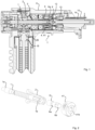
- Fig. 1 is a cross sectional view of a portion of an exemplary power tool according to one embodiment, in this case a handheld tightening tool.
- the tool comprises a housing H, an input shaft IS, a motor connected to the driving member 2 via a bevel gear 20, an output shaft and a two-speed transmission arranged between the input shaft and the output shaft. Further, the tool is connected to an external control unit operative to control the rotational speed of the motor which will be described in greater detail below when describing the functionality of the tool.
- the two-speed power transmission of the embodiment shown in fig. 1 comprises a planetary gear 4 and a gear shift assembly T for directing torque from the input shaft IS to the output shaft ⁇ through the planetary gear 4 in a high torque/low speed drive mode or past the planetary gear 4 in a low torque/high speed drive mode.
- the transmission is shown in fig. 1 in the low torque/high speed drive mode.
- the planetary gear 4 comprises a ring gear (or gear rim) secured in the housing H and a planet wheel carrier 41.
- the transmission assembly comprises a driving member 2, in the illustrated embodiment forming part of the bevel gear 20, and a driven member 1 drivingly connected to the output shaft.
- a coupling sleeve 6 is axially movable between a first position where the sleeve intercouples the driving member 2 and the driven member 1, i.e. the low torque/high speed mode illustrated in fig. 1 , and a second position intercoupling the planetary gear 4 - more particularly the planet carrier 4a the driven member 1.
- a linear actuator 13,14 is used to displace the coupling sleeve between said first and second position more particularly, in the illustrated embodiment, a linear DC servo motor comprising a solid stator housing 14, a coil assembly, and a linearly movable multi-pole magnetic push rod 13 arranged to push the coupling sleeve from the first to the second position.
- the linear motor further comprises an internal hall sensor configured to sense a position of the bar 13 and an internal control unit or controller board 15.
- a compression spring 3 is arranged to bias the coupling sleeve 6 toward the first position.
- the push bar engages a second element 12 of a coupling assembly arranged between the coupling sleeve 6 and the linear motor 13, 14.
- the second element 12 in the illustrated embodiment however forms part of the pushed bar.
- This coupling assembly further comprises a first element 8 in the form of a ball 8 arranged in the sleeve 6 at a first end 6a thereof and hence rotating along with the coupling sleeve 6.
- the rotation of the sleeve 6 is independent from the rotation of the push bar 13 of the linear motor (and hence that of the second element 12 forming part of the push bar 13).
- the ball 8 has a suitable size to fit the end 6a of the coupling sleeve 6 and the push bar 13 is arranged to engage the ball (i.e. push) in a position lying in the center of said sleeve (i.e. via the second element 12).
- A may be seen from fig. 1 and 2 , the driven member 1 is supported at a first end 1a by a bearing 50 and at a second end 1b comprises a first engaging portion 1b.
- the planet wheel carrier 41 similarly comprises a second engaging portion 41b.
- the power tool of the illustrated embodiment forms part of a system comprising an external control unit (not shown) operative to control the tool.
- the coupling sleeve 6 is initially biased towards the first position to perform run down - i.e. low torque/high speed mode. It follows that the push bar 13 as well is in a back position where the coupling sleeve 6 connects the driving member with the output shaft, fig. 1 .
- Run down ends when snug is reached, in the illustrated embodiment this is identified by the external control unit when a current limit threshold is passed.
- the linear motor receives a signal that run down is complete, displacement of the push bar 13 and hence the coupling sleeve 6 forwards towards the second position starts.
- the position of the push bar 13 and hence the position of the coupling sleeve 6 is monitored by the internal hall sensor such that it may be determined when the coupling sleeve engages the planetary gear, i.e. has reached the second position.
- a signal is sent to the external control unit and the final and actual tightening phase (i.e. high torque/low speed mode) starts. If however, the respective hex-shaped congruent cross sections 6a of the coupling sleeve 6 and the planet carrier misalign and the sleeve 6 fails to engage the planet wheel carrier 41, the linear motor effects a linear motion in a reverse direction (i.e. backwards).
- the forward movement is then repeated but combined with a simultaneous slow rotation of the motor and hence the carrier 41 to allow for a new position to facilitate engagement.
- the skilled person realizes that the forward movement and the rotation may be executed as consecutive steps as well.
- the torque is monitored by a torque transducer (not shown) and when the desired torque is reached the linear motor 13,14 receives a signal and the push bar 13 moves backwards to allow the sleeve 6 to engage high speed/low torque mode again.
- This movement of the coupling sleeve 6 may be combined with a simultaneous rotation of the motor to help the coupling sleeve to engage properly as described above.
Landscapes
- Engineering & Computer Science (AREA)
- Mechanical Engineering (AREA)
- General Engineering & Computer Science (AREA)
- Transmission Devices (AREA)
- Structure Of Transmissions (AREA)
Description
- The present invention generally relates to power tool, more particularly to a power tool comprising a two-speed gear assembly.
- Different types of power tools are known to be used in various industries, where one common type is tightening tools used for tightening of screws or bolts.
- One problem known to cause various design challenges in the field is that the working conditions and the requirements on the expected output tend to vary a lot during use for example with regards to the speed and torque required during different parts of a typical working operation. This is the case for example for the tightening tools mentioned above as during tightening of screws or nuts during the initial phase of the tightening, i.e. the so called run down, the torque needed is low whereas the rotation speed should ideally be high in order to reduce the time required for the operation whereas during the actual tightening phase, i.e. during the actual tightening of the joint, the torque required is higher.
- Power tools subjected to these types of varying requirements are however known to, in order to be able to provide the desired torque levels, include one or more transmissions such as for example one or more planetary gear steps connected in series.
- But, using such transmissions to achieve the high torque levels required for actual tightening, the rotational speed provided decreases correspondingly thus resulting in an undesired low rotational speed also during run down. This becomes a significant problem particularly in the field of power tools adapted to tighten large screws to very high torque values, where commonly a very low RPM results from the provision of the desired high torque, which in turn commonly makes the rundown phase unreasonably slow.
- In order to alleviate some of these problems, attempts have therefore been made to use two-speed power transmissions, i.e. transmissions where the force flow through the gear unit may be altered such that a higher rotational speed may be used during run down and the high torque/low speed mode only when needed during actual tightening. Examples of such known power tools are disclosed for example in
US2009/071673 A1 , which describes the preamble of claim 1, andEP2708329A1 . - However, there are many problems associated with such transmissions remaining. For example, one known problem is lack of control of the actual advance of the shifting operation, i.e. knowing if the shifting has in fact taken place correctly. Such lack of precise control over the actual current position of the gear elements may result in destroyed gears and couplings.
- Solutions have been proposed involving complex mechanism comprising synchronizing rings or bulky sensors, making the design complex as such and commonly requiring a lot of space. Hence, there exists a need for improvement in the field of two-speed gear units for power tools.
- Accordingly, it would be desirable to provide a power tool having an improved two speed transmission. In particular, it would be desirable to provide a transmission providing improved possibilities for controlling the gear shifting. To better address one or more of these concerns a gear unit for a tightening tool, a power tool comprising such a gear unit and a method for controlling such a power tool as defined in the independent claims is provided. Preferred embodiments are defined in the dependent claims.
- According to a first aspect of the invention a power tool comprising a two-speed power transmission is provided, the tool comprising a housing, an input shaft, an output shaft and a two-speed power transmission, the two-speed power transmission comprising a planetary gear and a two speed gear shift assembly for directing torque through the planetary gear in a high torque/low speed drive mode or past the planetary gear in a low torque/high speed drive mode. The gear shift assembly comprising a driving member drivingly connected to the input shaft, a driven member drivingly connected to the output shaft, an axially movable coupling sleeve arranged to intercouple in a first position the driving member and the driven member and to intercouple in a second position the planetary gear and the driven member, and a linear actuator arranged to displace an axially movable coupling sleeve between the first and second position, wherein the linear actuator comprises a linearly movable push bar arranged to displace the coupling sleeve between the first and second position.
- According to the first aspect, the two-speed transmission provides an inventive solution to the concerns described above by means of a design incorporating a gear shift mechanism directing torque through a planetary gear step in a high torque/low speed drive mode or past the planetary gear in a low torque/high speed drive mode, where improved possibilities to accurately control the gear shifting is provided by means of the utilization of a coupling sleeve displaced by a linear actuator.
- More particularly, as the linear actuator is arranged to displace the coupling sleeve, the engagement in the respective modes of operation (or lack thereof) may be determined based on the position of the linear actuator. The design therefore cleverly provides a two-speed power transmission capable of providing precise and accurate control of the gear shifting.
- According to one embodiment, the power tool further comprises a motor and means for monitoring the torque delivered by the tool. The means for monitoring a torque delivered by the tool may comprise for example a sensor such as a torque transducer. Other examples include circuitry adapted to monitor the motor current or other internally provided data related to the performance of the motor. The power tool may also form part of a system comprising the power tool and an external control unit operative to control the power tool.
- With regards to the power tool as such, according to one embodiment, the motor is an electric motor. The tool may for example be an electrical hand-held power tool chosen from the group comprising a screw driver, a nut runner, a drill and a grinder. The skilled person however realizes that only slight modification of the structure would be required for use with a stationary or fixtured tools. In some embodiments, the power tool may be a battery powered tool. In one embodiment, the power tool is a tool providing a higher tightening torque, for example in the range 2400-8000 Nm.
- According to one embodiment, the gear assembly further comprises a coupling assembly arranged between the coupling sleeve and the linear actuator, the coupling assembly comprising a first element rotationally coupled to the sleeve and a second element translationally coupled to the push bar, wherein a rotation of the first element is independent of a rotation of the second element and wherein the second element is arranged to push the first element in an axial direction. Hereby, the rotation of the sleeve and hence the motor does not affect the linear actuator and the adjustment of the axial position of the sleeve may take place independently of the rotation. The second element may form part of the push bar.
- In one embodiment, the gear assembly further comprises a coupling assembly arranged to couple (i.e. link or connect) the coupling sleeve and the linear actuator, the coupling assembly comprising a first element rotationally coupled to the sleeve and a second element translationally coupled to the push bar, wherein a rotation of the first element is independent of a rotation of the second element and wherein the second element is arranged to push the first element in an axial direction. Hereby, the rotation of the sleeve and hence the motor does not affect the linear actuator and the adjustment of the axial position of the sleeve may take place independently of the rotation. The second element may form part of the push bar and/or be formed by the push bar.
- According to one embodiment, the coupling sleeve is concentrically arranged with respect to the planetary gear, wherein the second element is adapted to engage the first element in a position lying in a center of the sleeve. This arrangement provides a compact space saving design. Further, such a design further simplifies the bearing arrangements required.
- According to one embodiment, the first element is a ball arranged at least partly in the sleeve, wherein the second element arranged to push the ball is formed by the push bar. Hereby, the end of the push bar may bear against the rotating bar to displace the sleeve. The ball may for example be arranged at the end of the sleeve facing the linear actuator, for example by means of a press fit or similar.
- According to one embodiment, the gear assembly further comprises a coupling assembly arranged between the coupling sleeve and the linear actuator, the coupling assembly comprising a first element rotationally coupled to the sleeve, wherein a rotation of the first element is independent of a rotation of the push bar and wherein the push bar is arranged to push the first element in an axial direction. Hereby, the rotation of the sleeve and hence the motor does not affect the linear actuator and the adjustment of the axial position of the sleeve may take place independently of the rotation. In one embodiment, the coupling sleeve is concentrically arranged with respect to the planetary gear and the push bar is adapted to engage the first element in a position lying in a center of the sleeve. In one embodiment, the first element is a ball arranged at least partly in the sleeve.
- In one embodiment, the coupling further comprises a second element translationally coupled to said push bar and adapted to engage said first element, wherein a rotation of said first element is independent of a rotation of said push bar and wherein said push bar is arranged to push said first element in an axial direction by means of pushing said second element.
- According to one embodiment, a first axially acting spring means is arranged for biasing the coupling sleeve toward the first position of the coupling sleeve. Examples include a compression spring arranged to bear against for example a suitable portion of the housing and acting on a second end of the sleeve.
- According to one embodiment, the first and second position is a first and second end position respectively, wherein the coupling sleeve is continuously movable there between and may be positioned at any position between the first and second end position. Or, in other words, the push bar of the linear actuator may be positioned at any position between a first and second end position. Preferably, the position of the push bar may be monitored over the whole interval.
- According to one embodiment, the driven member comprises a first engaging portion adapted to engage a corresponding congruent first portion of the coupling sleeve, and wherein the planetary gear comprises a planet wheel carrier comprising a second engaging portion adapted to engage a corresponding congruent second portion of the coupling sleeve. For example, according to one embodiment, at least one of the first and second engaging portion have a polygonal shape where examples include a square- or hex shaped cross section.
- According to one embodiment, the planetary gear is a first planetary gear step. According to one embodiment, the power tool further comprises a front gear unit, or second stage gear unit. In such an embodiment the inventive transmission may be arranged between the motor and the front- or second stage gear unit such that the driven member of the transmission engages the front gear, i.e. is drivingly connected to the output shaft via the front gear. This is advantageous in that the front gear unit for such a tool may be an interchangeable front gear unit, such that the front gear unit may be changed depending on the desired torque while the two speed transmission remains in or on the tool.
- According to one embodiment, the power tool further comprises a bevel gear arranged between the input shaft and the driving member, such that the driving member is connected to the input shaft via the bevel gear. This may be advantageous in that, due to the change of direction of the power train at the bevel gear, a design where the centered pushed rod described above may be more easily realized may be achieved.
- According to one embodiment, the linear actuator is a linear motor. For example a DC servo motor comprising a solid stator housing, a coil assembly, and a multi-pole magnetic push rod.
- According to one embodiment, the linear motor comprises at least one internal position sensor configure to sense a position of the push bar. Examples include an internal hall-sensor. Hereby, the position of the push rod may be continuously determined and monitored. In one embodiment, the liner motor further comprises a control unit configured to for example monitor and control the movement of the push rod as well as communicate with for example an external control unit configured to control the power tool.
- According to a second aspect of the present invention, a two-speed power transmission for a power tool according to any of the embodiment described above is provided, the transmission comprising a planetary gear and a two speed gear shift assembly for directing torque through the planetary gear in a high torque/low speed drive mode or past the planetary gear in a low torque/high speed drive mode. The gear shift assembly comprising a driving member drivingly connected to the input shaft, a driven member drivingly connected to the output shaft, a coupling sleeve arranged to intercouple in a first position the driving member and the driven member and to intercouple in a second position the planet wheel carrier and the driven member, and a linear actuator arranged to displace the coupling sleeve between the first and second position, wherein the linear actuator is a linear actuator comprising a linearly movable push bar arranged to displace said coupling sleeve between said first and second position.
- Objectives, advantages and features of the transmission conceivable within the scope of the second aspect of the invention are readily understood by the foregoing discussion referring to the first aspect of the invention.
- According to a third aspect of the present invention, a method for controlling a power tool comprising a planetary gear and a two speed gear shift assembly for directing torque through the planetary gear in a high torque/low speed drive mode or past the planetary gear in a low torque/high speed drive mode by means of a coupling sleeve and a linear actuator arranged to displace the coupling sleeve, the method comprising the steps of running the tool in the low torque/high speed drive mode of operation in which the coupling sleeve is arranged in a first position directing torque past the planetary gear, identifying that snug has been reached, displacing the coupling sleeve forwards by an axial movement in a first direction by means of the linear actuator to arrive at the second position and running the tool in the high torque/low speed drive mode of operation in which the coupling sleeve is arranged in the second position directing torque through the planetary gear.
- According to one embodiment, the method is a method in a power tool comprising a two speed transmission according to any of the embodiments described in the foregoing, the method comprising the steps of running the tool in the low torque/high speed drive mode of operation in which the coupling sleeve is arranged in said first position intercoupling said driving member and driven member, identifying that snug has been reached, displacing said coupling sleeve forwards by an axial movement in a first direction by means of said linear motor to arrive at said second position and running the tool in the high torque/low speed drive mode of operation in which the coupling sleeve is arranged in the second position intercoupling said planet wheel carrier and said driven member. By forwards should be understood a direction towards the end of the output shaft where a socket or similar will engage.
- I.e., in other words, when run down (i.e. low torque/high speed mode) start the push bar and hence the coupling sleeve is in the first, i.e. back position where the coupling sleeve connects the driving member with the output shaft. Run down ends when snug is reached, this may for example be identified by a passing of a current limit threshold. Snug, for the sake of completeness, is the point in where the run down phase passes into the actual tightening phase. These tightening conditions may be monitored for example by an external control unit. This is followed by a signal to the linear motor that run down is complete, and displacement of the push bar and hence the coupling sleeve forwards towards the second position starts. As the coupling sleeve engages the planetary gear, i.e. is positioned at said second position, a signal may be sent for example to the external control unit indicating that low speed gear is in position. Now, the final and actual tightening phase (i.e. high torque/low speed) may start.
- According to one embodiment, the step of arriving at the second position further comprises, if the coupling sleeve fails to engage the planetary gear, effecting a displacement backwards by an axial movement in a second opposite direction of the linear actuator backwards, effecting a rotation of the planetary gear and moving the coupling sleeve forwards by an axial movement in the first direction by means of the linear actuator to arrive at the second position.
- According to one embodiment, the method is a method in a power tool comprising a two speed transmission according to any of the embodiments described in the foregoing and the step of arriving at the second position further comprises if the coupling sleeve fails to engage the planet wheel carrier, effecting a displacement backwards by an axial movement in a second opposite direction of the linear motor backwards, effecting a rotation of the driving member and moving the coupling sleeve forwards by an axial movement in the first direction by means of the linear motor to arrive at the second position.
- I.e., if the push bar fails to reach the front or first position due to for example a rotational miss-match between the cross section of the sleeve and the corresponding surfaces of the planetary gear to be engaged, the direction of axial movement is reversed and the push bar moves back a small distance and, possibly simultaneously, the motor rotates the planet carrier to allow for a new position for the coupling sleeve to engage. Hereby, the change between the drive modes of the transmission may be facilitated.
- In one embodiment, the method may further comprise the steps of identifying that a target torque has been reached and displacing the coupling sleeve backwards by an axial movement in a second direction by means of the linear motor to return to the first position. I.e. the torque may be monitored by means of e.g. a torque transducer, and when the desired torque is reached the linear motor receives a signal and return to engage high speed/low torque mode again. This movement of the coupling sleeve may be followed by a, or combined with a simultaneous, rotation of the motor to help the coupling sleeve to engage properly as described above.
- Objectives, advantages and features of the method conceivable within the scope of the third aspect of the invention are readily understood by the foregoing discussion referring to the second aspect of the invention.
- Further objectives of, features of and advantages of the present invention will become apparent when studying the following detailed disclosure, the drawings and the appended claims. Those skilled in the art realize that different features of the present invention can be combined to create embodiments other than those described in the following.
- The invention will be described in the following illustrative and non-limiting detailed description of exemplary embodiments, with reference to the appended drawing, on which
-
Figure 1 is a cross sectional view of an exemplary power tool comprising a two-speed power transmission according to one embodiment. -
Figure 2 is a first perspective view of some of the components of an exemplary transmission according to one embodiment. - All figures are schematic, not necessarily to scale and generally only show parts which are necessary in order to elucidate the invention, wherein other parts may be omitted or merely suggested.
-
Fig. 1 is a cross sectional view of a portion of an exemplary power tool according to one embodiment, in this case a handheld tightening tool. The tool comprises a housing H, an input shaft IS, a motor connected to the drivingmember 2 via abevel gear 20, an output shaft and a two-speed transmission arranged between the input shaft and the output shaft. Further, the tool is connected to an external control unit operative to control the rotational speed of the motor which will be described in greater detail below when describing the functionality of the tool. - The two-speed power transmission of the embodiment shown in
fig. 1 comprises a planetary gear 4 and a gear shift assembly T for directing torque from the input shaft IS to the output shaft ^through the planetary gear 4 in a high torque/low speed drive mode or past the planetary gear 4 in a low torque/high speed drive mode. The transmission is shown infig. 1 in the low torque/high speed drive mode. - The planetary gear 4 comprises a ring gear (or gear rim) secured in the housing H and a
planet wheel carrier 41. The transmission assembly comprises a drivingmember 2, in the illustrated embodiment forming part of thebevel gear 20, and a driven member 1 drivingly connected to the output shaft. - A
coupling sleeve 6 is axially movable between a first position where the sleeve intercouples the drivingmember 2 and the driven member 1, i.e. the low torque/high speed mode illustrated infig. 1 , and a second position intercoupling the planetary gear 4 - more particularly the planet carrier 4a the driven member 1. - A
linear actuator solid stator housing 14, a coil assembly, and a linearly movable multi-polemagnetic push rod 13 arranged to push the coupling sleeve from the first to the second position. The linear motor further comprises an internal hall sensor configured to sense a position of thebar 13 and an internal control unit orcontroller board 15. Acompression spring 3 is arranged to bias thecoupling sleeve 6 toward the first position. - In the illustrated embodiment, the push bar engages a
second element 12 of a coupling assembly arranged between thecoupling sleeve 6 and thelinear motor second element 12 in the illustrated embodiment however forms part of the pushed bar. This coupling assembly further comprises afirst element 8 in the form of aball 8 arranged in thesleeve 6 at afirst end 6a thereof and hence rotating along with thecoupling sleeve 6. The rotation of thesleeve 6 is independent from the rotation of thepush bar 13 of the linear motor (and hence that of thesecond element 12 forming part of the push bar 13). Theball 8 has a suitable size to fit theend 6a of thecoupling sleeve 6 and thepush bar 13 is arranged to engage the ball (i.e. push) in a position lying in the center of said sleeve (i.e. via the second element 12). - The engagement between the
coupling sleeve 6 and, as in the first mode, the driven member 1 and in the second mode theplanet carrier 41 will now be described with reference tofig. 2 showing thesleeve 6, theplanet carrier 41, drivingmember 2 and the driven member 1 in a perspective view. - A may be seen from
fig. 1 and 2 , the driven member 1 is supported at afirst end 1a by a bearing 50 and at asecond end 1b comprises a firstengaging portion 1b. Theplanet wheel carrier 41 similarly comprises a secondengaging portion 41b. These engagingportions coupling sleeve 6, the respective interacting surfaces have a congruent shape, in the illustrated embodiment a hex-shape in both instances. - In operation, the power tool of the illustrated embodiment forms part of a system comprising an external control unit (not shown) operative to control the tool.
- The
coupling sleeve 6 is initially biased towards the first position to perform run down - i.e. low torque/high speed mode. It follows that thepush bar 13 as well is in a back position where thecoupling sleeve 6 connects the driving member with the output shaft,fig. 1 . - Run down ends when snug is reached, in the illustrated embodiment this is identified by the external control unit when a current limit threshold is passed. As the linear motor receives a signal that run down is complete, displacement of the
push bar 13 and hence thecoupling sleeve 6 forwards towards the second position starts. - The position of the
push bar 13 and hence the position of thecoupling sleeve 6 is monitored by the internal hall sensor such that it may be determined when the coupling sleeve engages the planetary gear, i.e. has reached the second position. A signal is sent to the external control unit and the final and actual tightening phase (i.e. high torque/low speed mode) starts. If however, the respective hex-shapedcongruent cross sections 6a of thecoupling sleeve 6 and the planet carrier misalign and thesleeve 6 fails to engage theplanet wheel carrier 41, the linear motor effects a linear motion in a reverse direction (i.e. backwards). The forward movement is then repeated but combined with a simultaneous slow rotation of the motor and hence thecarrier 41 to allow for a new position to facilitate engagement. The skilled person realizes that the forward movement and the rotation may be executed as consecutive steps as well. - During final tightening, the torque is monitored by a torque transducer (not shown) and when the desired torque is reached the
linear motor push bar 13 moves backwards to allow thesleeve 6 to engage high speed/low torque mode again. This movement of thecoupling sleeve 6 may be combined with a simultaneous rotation of the motor to help the coupling sleeve to engage properly as described above.
Claims (13)
- Two-speed power transmission for a power tool, said transmission comprising a planetary gear (4) and a two speed gear shift assembly (T) for directing torque through said planetary gear (4) in a high torque/low speed drive mode or past said planetary gear (4) in a low torque/high speed drive mode;said gear shift assembly (T) comprisinga driving member (2) drivingly connectable to an input shaft (IS),a driven member (1) drivingly connectable to an output shaft,a coupling sleeve (6) arranged to intercouple in a first position said driving member (2) and said driven member (1) and to intercouple in a second position said planetary gear (4) and said driven member (1), anda linear actuator (13, 14) arranged to displace said coupling sleeve (6) between said first and second position, wherein said linear actuator (13, 14) comprises a linearly movable push bar (13) arranged to displace said coupling sleeve (6) between said first and second position,characterized in that said gear assembly (T) further comprises a coupling assembly arranged between said coupling sleeve (6) and said linear actuator (13, 14), said coupling assembly comprising a first element (8) rotationally coupled to said sleeve (6),wherein a rotation of said first element (8) is independent of a rotation of said push bar (13) and wherein said push bar (13) is arranged to push said first element (8) in an axial direction, wherein said coupling sleeve (6) is concentrically arranged with respect to said planetary gear (4) and wherein said push bar (13) is adapted to engage said first element (8) in a position lying in a center of said sleeve (6).
- Power tool comprising:a housing (H);an input shaft (IS);an output shaft; anda two-speed power transmission according to claim 1.
- Power tool according to claim 2, wherein said first element (8) is a ball arranged at least partly in said sleeve.
- Power tool according to any of the preceding claims, wherein a first axially acting spring means (3) is arranged for biasing said coupling sleeve (6) toward said first position of said coupling sleeve (6).
- Power tool according to any of the preceding claims, wherein said first and second position is a first and second end position and wherein said coupling sleeve (6) is continuously movable there between and may be positioned at any position between said first and second end position.
- Power tool according to any of the preceding claims, wherein said driven member (1) comprises a first engaging portion (1b) adapted to engage a corresponding congruent first portion (6a) of said coupling sleeve (6), and wherein said planetary gear comprises a planet wheel carrier (41) comprising a second engaging portion (41b) adapted to engage a corresponding congruent second portion (6b) of said coupling sleeve (6).
- Power tool according to claim 6, wherein at least one of said first and second engaging portion (6a, 6b) have a polygonal cross section.
- Power tool according to any of the preceding claims, further comprising a bevel gear (20) arranged between said input shaft (IS) and said driving member (2), such that said driving member is connected to said input shaft via said bevel gear.
- Power tool according to any of the preceding claims, wherein said linear actuator (13, 14) is a linear DC servo motor comprising a solid stator housing, a coil assembly, and a multi-pole magnetic push rod.
- Power tool according to any of the preceding claims, wherein said linear actuator (13, 14) comprises at least one internal position sensor configure to sense a position of said push bar.
- Power tool according to any of the preceding claims, wherein said planetary gear (4) is a first planetary gear step.
- Method for controlling a power tool according to any of claims 2-11, said method comprising the steps of:running the tool in the low torque/high speed drive mode of operation in which the coupling sleeve (6) is arranged in a first position directing torque past said planetary gear (4);identifying that snug has been reached;displacing said coupling sleeve forwards by an axial movement in a first direction by means of said linear actuator (13, 14) to arrive at said second position; andrunning the tool in the high torque/low speed drive mode of operation in which the coupling sleeve is arranged in the second position directing torque through said planetary gear.
- Method according to claim 12, wherein the step of arriving at said second position further comprises, if said coupling sleeve fails to engage said planetary gear,effecting a displacement of said coupling sleeve backwards by an axial movement in a second opposite direction of said linear actuator;effecting a rotation of said planetary gear; andeffecting a displacement of said coupling sleeve forwards by an axial movement in said first direction of said linear actuator to arrive at said second position.
Applications Claiming Priority (2)
| Application Number | Priority Date | Filing Date | Title |
|---|---|---|---|
| SE1930352A SE543799C2 (en) | 2019-10-31 | 2019-10-31 | Power tool and two-speed gear assembly for a power tool |
| PCT/EP2020/079086 WO2021083680A1 (en) | 2019-10-31 | 2020-10-15 | Power tool and two-speed gear assembly for a power tool |
Publications (2)
| Publication Number | Publication Date |
|---|---|
| EP4051453A1 EP4051453A1 (en) | 2022-09-07 |
| EP4051453B1 true EP4051453B1 (en) | 2024-02-28 |
Family
ID=72964661
Family Applications (1)
| Application Number | Title | Priority Date | Filing Date |
|---|---|---|---|
| EP20793613.9A Active EP4051453B1 (en) | 2019-10-31 | 2020-10-15 | Method, power tool and two-speed gear assembly for a power tool |
Country Status (7)
| Country | Link |
|---|---|
| US (1) | US12186876B2 (en) |
| EP (1) | EP4051453B1 (en) |
| JP (1) | JP7608449B2 (en) |
| KR (1) | KR102879290B1 (en) |
| CN (1) | CN114616410B (en) |
| SE (1) | SE543799C2 (en) |
| WO (1) | WO2021083680A1 (en) |
Families Citing this family (6)
| Publication number | Priority date | Publication date | Assignee | Title |
|---|---|---|---|---|
| US11871924B2 (en) * | 2018-09-21 | 2024-01-16 | Covidien Lp | Hand-held surgical instruments |
| WO2023069724A1 (en) | 2021-10-21 | 2023-04-27 | Speede Fitness, Llc | Resistance training machine and methods of use |
| US20260027681A1 (en) * | 2022-07-14 | 2026-01-29 | Milwaukee Electric Tool Corporation | Power tool with automatic shifting mechanism |
| TWI822317B (en) * | 2022-09-08 | 2023-11-11 | 瞬豐實業股份有限公司 | Torque sensing device for power tools |
| SE2430113A1 (en) * | 2024-03-06 | 2025-07-08 | Atlas Copco Ind Technique Ab | Power tool and torque responsive transmission for a power tool |
| SE2430272A1 (en) * | 2024-05-16 | 2025-11-11 | Atlas Copco Ind Technique Ab | Power tool and two-speed gear assembly for a power tool |
Family Cites Families (19)
| Publication number | Priority date | Publication date | Assignee | Title |
|---|---|---|---|---|
| JPS4623659Y1 (en) * | 1968-01-12 | 1971-08-14 | ||
| BE791093A (en) * | 1971-12-30 | 1973-03-01 | Gardner Denver Co | TOOL SPEED AUTOMATIC VARIATOR |
| JPS59192465A (en) * | 1983-04-13 | 1984-10-31 | 前田金属工業株式会社 | Power rotary tool |
| DE3671185D1 (en) * | 1985-12-06 | 1990-06-21 | Desoutter Ltd | TWO-SPEED TRANSMISSION. |
| US5897454A (en) * | 1996-01-31 | 1999-04-27 | Black & Decker Inc. | Automatic variable transmission for power tool |
| DE19611459C2 (en) * | 1996-03-22 | 1998-07-16 | Klement Klaus Dieter | Spindle drive for a machine tool |
| AU2007201851B2 (en) * | 2006-04-28 | 2009-12-03 | Unex Corporation | Power-driven torque intensifier |
| EP2030710B1 (en) * | 2007-08-29 | 2014-04-23 | Positec Power Tools (Suzhou) Co., Ltd. | Power tool and control system for a power tool |
| US8460153B2 (en) * | 2009-12-23 | 2013-06-11 | Black & Decker Inc. | Hybrid impact tool with two-speed transmission |
| US20110303432A1 (en) * | 2010-06-14 | 2011-12-15 | Stauffer Joseph G | Power tool transmission |
| US9481080B2 (en) * | 2011-07-29 | 2016-11-01 | Black & Decker Inc. | Multispeed power tool |
| JP5963136B2 (en) | 2012-09-13 | 2016-08-03 | パナソニックIpマネジメント株式会社 | Electric tool |
| DE102013209310A1 (en) * | 2013-05-21 | 2014-11-27 | Zf Friedrichshafen Ag | Switchable planetary gear |
| JP6335296B2 (en) | 2013-08-08 | 2018-05-30 | アトラス・コプコ・インダストリアル・テクニーク・アクチボラグ | Power tool with flywheel and gear for accelerating the flywheel |
| JP6517502B2 (en) | 2014-12-02 | 2019-05-22 | 株式会社Ihiエアロスペース | Two-speed transmission |
| DE102015110504A1 (en) * | 2015-06-30 | 2017-01-19 | Festool Gmbh | The handheld machine tool |
| DE102015226085A1 (en) * | 2015-12-18 | 2017-06-22 | Robert Bosch Gmbh | Hand tool with a switching unit |
| CN207642350U (en) * | 2017-08-11 | 2018-07-24 | 宝时得科技(中国)有限公司 | Power tool |
| CN208483267U (en) * | 2018-05-18 | 2019-02-12 | 宝时得科技(中国)有限公司 | Electric tool |
-
2019
- 2019-10-31 SE SE1930352A patent/SE543799C2/en unknown
-
2020
- 2020-10-15 JP JP2022524202A patent/JP7608449B2/en active Active
- 2020-10-15 KR KR1020227018190A patent/KR102879290B1/en active Active
- 2020-10-15 US US17/767,169 patent/US12186876B2/en active Active
- 2020-10-15 WO PCT/EP2020/079086 patent/WO2021083680A1/en not_active Ceased
- 2020-10-15 CN CN202080076309.2A patent/CN114616410B/en active Active
- 2020-10-15 EP EP20793613.9A patent/EP4051453B1/en active Active
Also Published As
| Publication number | Publication date |
|---|---|
| CN114616410A (en) | 2022-06-10 |
| KR20220086688A (en) | 2022-06-23 |
| JP7608449B2 (en) | 2025-01-06 |
| JP2023501140A (en) | 2023-01-18 |
| US12186876B2 (en) | 2025-01-07 |
| SE543799C2 (en) | 2021-07-27 |
| US20220410361A1 (en) | 2022-12-29 |
| CN114616410B (en) | 2025-02-21 |
| WO2021083680A1 (en) | 2021-05-06 |
| KR102879290B1 (en) | 2025-11-03 |
| EP4051453A1 (en) | 2022-09-07 |
| SE1930352A1 (en) | 2021-05-01 |
Similar Documents
| Publication | Publication Date | Title |
|---|---|---|
| US12186876B2 (en) | Power tool and two-speed gear assembly for a power tool | |
| US10293687B2 (en) | Four-wheel drive vehicle and control apparatus for four-wheel drive vehicle | |
| US11858105B2 (en) | Power tool and torque-responsive gear unit for a power tool | |
| CN100362264C (en) | Continuously variable transmission and motorcycle comprising same | |
| KR101453114B1 (en) | Device for actuating a gearwheel, which is designed as a loose wheel, of a transmission device | |
| EP0302244A2 (en) | Rotary electric tool | |
| CN101377229A (en) | Speed change tool and speed change control method thereof | |
| US5127281A (en) | Composite motion guide device | |
| US11319999B2 (en) | Assembly for the selective coupling of two coaxially arranged shafts | |
| US20110303432A1 (en) | Power tool transmission | |
| JP2023501140A5 (en) | ||
| US8770053B2 (en) | Transmission device | |
| CN222415938U (en) | Power Tools | |
| US8973605B2 (en) | Actuating device for housed or housingless valves | |
| SE516939C2 (en) | Multiple screwdrivers with individually switchable and in line screwdrivers | |
| US20080282840A1 (en) | Drive Shaft Moving Device | |
| CN223972390U (en) | Transmission mechanism for disconnectable stabilizer bar | |
| EP1092896A1 (en) | Automatic variable transmission for a power tool | |
| CN108687705B (en) | Assembly method of torsion shear wrench | |
| CN115635350B (en) | A three-axis, three-speed spindle box transmission device for CNC lathes used for disc machining. | |
| JPH11333643A (en) | Multi-axis nutrunner | |
| JP2008057575A (en) | Automatic transmission actuator for manual transmission |
Legal Events
| Date | Code | Title | Description |
|---|---|---|---|
| STAA | Information on the status of an ep patent application or granted ep patent |
Free format text: STATUS: UNKNOWN |
|
| STAA | Information on the status of an ep patent application or granted ep patent |
Free format text: STATUS: THE INTERNATIONAL PUBLICATION HAS BEEN MADE |
|
| PUAI | Public reference made under article 153(3) epc to a published international application that has entered the european phase |
Free format text: ORIGINAL CODE: 0009012 |
|
| STAA | Information on the status of an ep patent application or granted ep patent |
Free format text: STATUS: REQUEST FOR EXAMINATION WAS MADE |
|
| 17P | Request for examination filed |
Effective date: 20220429 |
|
| AK | Designated contracting states |
Kind code of ref document: A1 Designated state(s): AL AT BE BG CH CY CZ DE DK EE ES FI FR GB GR HR HU IE IS IT LI LT LU LV MC MK MT NL NO PL PT RO RS SE SI SK SM TR |
|
| DAV | Request for validation of the european patent (deleted) | ||
| DAX | Request for extension of the european patent (deleted) | ||
| STAA | Information on the status of an ep patent application or granted ep patent |
Free format text: STATUS: EXAMINATION IS IN PROGRESS |
|
| 17Q | First examination report despatched |
Effective date: 20230511 |
|
| GRAP | Despatch of communication of intention to grant a patent |
Free format text: ORIGINAL CODE: EPIDOSNIGR1 |
|
| STAA | Information on the status of an ep patent application or granted ep patent |
Free format text: STATUS: GRANT OF PATENT IS INTENDED |
|
| INTG | Intention to grant announced |
Effective date: 20231124 |
|
| GRAS | Grant fee paid |
Free format text: ORIGINAL CODE: EPIDOSNIGR3 |
|
| GRAA | (expected) grant |
Free format text: ORIGINAL CODE: 0009210 |
|
| STAA | Information on the status of an ep patent application or granted ep patent |
Free format text: STATUS: THE PATENT HAS BEEN GRANTED |
|
| AK | Designated contracting states |
Kind code of ref document: B1 Designated state(s): AL AT BE BG CH CY CZ DE DK EE ES FI FR GB GR HR HU IE IS IT LI LT LU LV MC MK MT NL NO PL PT RO RS SE SI SK SM TR |
|
| REG | Reference to a national code |
Ref country code: GB Ref legal event code: FG4D |
|
| REG | Reference to a national code |
Ref country code: CH Ref legal event code: EP |
|
| REG | Reference to a national code |
Ref country code: DE Ref legal event code: R096 Ref document number: 602020026516 Country of ref document: DE |
|
| REG | Reference to a national code |
Ref country code: IE Ref legal event code: FG4D |
|
| P01 | Opt-out of the competence of the unified patent court (upc) registered |
Effective date: 20240308 |
|
| REG | Reference to a national code |
Ref country code: LT Ref legal event code: MG9D |
|
| PG25 | Lapsed in a contracting state [announced via postgrant information from national office to epo] |
Ref country code: IS Free format text: LAPSE BECAUSE OF FAILURE TO SUBMIT A TRANSLATION OF THE DESCRIPTION OR TO PAY THE FEE WITHIN THE PRESCRIBED TIME-LIMIT Effective date: 20240628 |
|
| REG | Reference to a national code |
Ref country code: NL Ref legal event code: MP Effective date: 20240228 |
|
| PG25 | Lapsed in a contracting state [announced via postgrant information from national office to epo] |
Ref country code: LT Free format text: LAPSE BECAUSE OF FAILURE TO SUBMIT A TRANSLATION OF THE DESCRIPTION OR TO PAY THE FEE WITHIN THE PRESCRIBED TIME-LIMIT Effective date: 20240228 |
|
| PG25 | Lapsed in a contracting state [announced via postgrant information from national office to epo] |
Ref country code: GR Free format text: LAPSE BECAUSE OF FAILURE TO SUBMIT A TRANSLATION OF THE DESCRIPTION OR TO PAY THE FEE WITHIN THE PRESCRIBED TIME-LIMIT Effective date: 20240529 |
|
| PG25 | Lapsed in a contracting state [announced via postgrant information from national office to epo] |
Ref country code: HR Free format text: LAPSE BECAUSE OF FAILURE TO SUBMIT A TRANSLATION OF THE DESCRIPTION OR TO PAY THE FEE WITHIN THE PRESCRIBED TIME-LIMIT Effective date: 20240228 Ref country code: RS Free format text: LAPSE BECAUSE OF FAILURE TO SUBMIT A TRANSLATION OF THE DESCRIPTION OR TO PAY THE FEE WITHIN THE PRESCRIBED TIME-LIMIT Effective date: 20240528 Ref country code: NL Free format text: LAPSE BECAUSE OF FAILURE TO SUBMIT A TRANSLATION OF THE DESCRIPTION OR TO PAY THE FEE WITHIN THE PRESCRIBED TIME-LIMIT Effective date: 20240228 |
|
| PG25 | Lapsed in a contracting state [announced via postgrant information from national office to epo] |
Ref country code: ES Free format text: LAPSE BECAUSE OF FAILURE TO SUBMIT A TRANSLATION OF THE DESCRIPTION OR TO PAY THE FEE WITHIN THE PRESCRIBED TIME-LIMIT Effective date: 20240228 |
|
| PG25 | Lapsed in a contracting state [announced via postgrant information from national office to epo] |
Ref country code: RS Free format text: LAPSE BECAUSE OF FAILURE TO SUBMIT A TRANSLATION OF THE DESCRIPTION OR TO PAY THE FEE WITHIN THE PRESCRIBED TIME-LIMIT Effective date: 20240528 Ref country code: NO Free format text: LAPSE BECAUSE OF FAILURE TO SUBMIT A TRANSLATION OF THE DESCRIPTION OR TO PAY THE FEE WITHIN THE PRESCRIBED TIME-LIMIT Effective date: 20240528 Ref country code: NL Free format text: LAPSE BECAUSE OF FAILURE TO SUBMIT A TRANSLATION OF THE DESCRIPTION OR TO PAY THE FEE WITHIN THE PRESCRIBED TIME-LIMIT Effective date: 20240228 Ref country code: LT Free format text: LAPSE BECAUSE OF FAILURE TO SUBMIT A TRANSLATION OF THE DESCRIPTION OR TO PAY THE FEE WITHIN THE PRESCRIBED TIME-LIMIT Effective date: 20240228 Ref country code: IS Free format text: LAPSE BECAUSE OF FAILURE TO SUBMIT A TRANSLATION OF THE DESCRIPTION OR TO PAY THE FEE WITHIN THE PRESCRIBED TIME-LIMIT Effective date: 20240628 Ref country code: HR Free format text: LAPSE BECAUSE OF FAILURE TO SUBMIT A TRANSLATION OF THE DESCRIPTION OR TO PAY THE FEE WITHIN THE PRESCRIBED TIME-LIMIT Effective date: 20240228 Ref country code: GR Free format text: LAPSE BECAUSE OF FAILURE TO SUBMIT A TRANSLATION OF THE DESCRIPTION OR TO PAY THE FEE WITHIN THE PRESCRIBED TIME-LIMIT Effective date: 20240529 Ref country code: FI Free format text: LAPSE BECAUSE OF FAILURE TO SUBMIT A TRANSLATION OF THE DESCRIPTION OR TO PAY THE FEE WITHIN THE PRESCRIBED TIME-LIMIT Effective date: 20240228 Ref country code: ES Free format text: LAPSE BECAUSE OF FAILURE TO SUBMIT A TRANSLATION OF THE DESCRIPTION OR TO PAY THE FEE WITHIN THE PRESCRIBED TIME-LIMIT Effective date: 20240228 Ref country code: BG Free format text: LAPSE BECAUSE OF FAILURE TO SUBMIT A TRANSLATION OF THE DESCRIPTION OR TO PAY THE FEE WITHIN THE PRESCRIBED TIME-LIMIT Effective date: 20240228 |
|
| PG25 | Lapsed in a contracting state [announced via postgrant information from national office to epo] |
Ref country code: PL Free format text: LAPSE BECAUSE OF FAILURE TO SUBMIT A TRANSLATION OF THE DESCRIPTION OR TO PAY THE FEE WITHIN THE PRESCRIBED TIME-LIMIT Effective date: 20240228 Ref country code: PT Free format text: LAPSE BECAUSE OF FAILURE TO SUBMIT A TRANSLATION OF THE DESCRIPTION OR TO PAY THE FEE WITHIN THE PRESCRIBED TIME-LIMIT Effective date: 20240628 |
|
| REG | Reference to a national code |
Ref country code: AT Ref legal event code: MK05 Ref document number: 1660829 Country of ref document: AT Kind code of ref document: T Effective date: 20240228 |
|
| PG25 | Lapsed in a contracting state [announced via postgrant information from national office to epo] |
Ref country code: SE Free format text: LAPSE BECAUSE OF FAILURE TO SUBMIT A TRANSLATION OF THE DESCRIPTION OR TO PAY THE FEE WITHIN THE PRESCRIBED TIME-LIMIT Effective date: 20240228 Ref country code: PT Free format text: LAPSE BECAUSE OF FAILURE TO SUBMIT A TRANSLATION OF THE DESCRIPTION OR TO PAY THE FEE WITHIN THE PRESCRIBED TIME-LIMIT Effective date: 20240628 Ref country code: PL Free format text: LAPSE BECAUSE OF FAILURE TO SUBMIT A TRANSLATION OF THE DESCRIPTION OR TO PAY THE FEE WITHIN THE PRESCRIBED TIME-LIMIT Effective date: 20240228 Ref country code: LV Free format text: LAPSE BECAUSE OF FAILURE TO SUBMIT A TRANSLATION OF THE DESCRIPTION OR TO PAY THE FEE WITHIN THE PRESCRIBED TIME-LIMIT Effective date: 20240228 |
|
| PG25 | Lapsed in a contracting state [announced via postgrant information from national office to epo] |
Ref country code: DK Free format text: LAPSE BECAUSE OF FAILURE TO SUBMIT A TRANSLATION OF THE DESCRIPTION OR TO PAY THE FEE WITHIN THE PRESCRIBED TIME-LIMIT Effective date: 20240228 |
|
| PG25 | Lapsed in a contracting state [announced via postgrant information from national office to epo] |
Ref country code: SM Free format text: LAPSE BECAUSE OF FAILURE TO SUBMIT A TRANSLATION OF THE DESCRIPTION OR TO PAY THE FEE WITHIN THE PRESCRIBED TIME-LIMIT Effective date: 20240228 |
|
| PG25 | Lapsed in a contracting state [announced via postgrant information from national office to epo] |
Ref country code: CZ Free format text: LAPSE BECAUSE OF FAILURE TO SUBMIT A TRANSLATION OF THE DESCRIPTION OR TO PAY THE FEE WITHIN THE PRESCRIBED TIME-LIMIT Effective date: 20240228 Ref country code: EE Free format text: LAPSE BECAUSE OF FAILURE TO SUBMIT A TRANSLATION OF THE DESCRIPTION OR TO PAY THE FEE WITHIN THE PRESCRIBED TIME-LIMIT Effective date: 20240228 |
|
| PG25 | Lapsed in a contracting state [announced via postgrant information from national office to epo] |
Ref country code: AT Free format text: LAPSE BECAUSE OF FAILURE TO SUBMIT A TRANSLATION OF THE DESCRIPTION OR TO PAY THE FEE WITHIN THE PRESCRIBED TIME-LIMIT Effective date: 20240228 |
|
| PG25 | Lapsed in a contracting state [announced via postgrant information from national office to epo] |
Ref country code: SK Free format text: LAPSE BECAUSE OF FAILURE TO SUBMIT A TRANSLATION OF THE DESCRIPTION OR TO PAY THE FEE WITHIN THE PRESCRIBED TIME-LIMIT Effective date: 20240228 |
|
| PG25 | Lapsed in a contracting state [announced via postgrant information from national office to epo] |
Ref country code: SM Free format text: LAPSE BECAUSE OF FAILURE TO SUBMIT A TRANSLATION OF THE DESCRIPTION OR TO PAY THE FEE WITHIN THE PRESCRIBED TIME-LIMIT Effective date: 20240228 Ref country code: SK Free format text: LAPSE BECAUSE OF FAILURE TO SUBMIT A TRANSLATION OF THE DESCRIPTION OR TO PAY THE FEE WITHIN THE PRESCRIBED TIME-LIMIT Effective date: 20240228 Ref country code: RO Free format text: LAPSE BECAUSE OF FAILURE TO SUBMIT A TRANSLATION OF THE DESCRIPTION OR TO PAY THE FEE WITHIN THE PRESCRIBED TIME-LIMIT Effective date: 20240228 Ref country code: EE Free format text: LAPSE BECAUSE OF FAILURE TO SUBMIT A TRANSLATION OF THE DESCRIPTION OR TO PAY THE FEE WITHIN THE PRESCRIBED TIME-LIMIT Effective date: 20240228 Ref country code: DK Free format text: LAPSE BECAUSE OF FAILURE TO SUBMIT A TRANSLATION OF THE DESCRIPTION OR TO PAY THE FEE WITHIN THE PRESCRIBED TIME-LIMIT Effective date: 20240228 Ref country code: CZ Free format text: LAPSE BECAUSE OF FAILURE TO SUBMIT A TRANSLATION OF THE DESCRIPTION OR TO PAY THE FEE WITHIN THE PRESCRIBED TIME-LIMIT Effective date: 20240228 Ref country code: AT Free format text: LAPSE BECAUSE OF FAILURE TO SUBMIT A TRANSLATION OF THE DESCRIPTION OR TO PAY THE FEE WITHIN THE PRESCRIBED TIME-LIMIT Effective date: 20240228 |
|
| REG | Reference to a national code |
Ref country code: DE Ref legal event code: R097 Ref document number: 602020026516 Country of ref document: DE |
|
| PG25 | Lapsed in a contracting state [announced via postgrant information from national office to epo] |
Ref country code: IT Free format text: LAPSE BECAUSE OF FAILURE TO SUBMIT A TRANSLATION OF THE DESCRIPTION OR TO PAY THE FEE WITHIN THE PRESCRIBED TIME-LIMIT Effective date: 20240228 |
|
| PG25 | Lapsed in a contracting state [announced via postgrant information from national office to epo] |
Ref country code: IT Free format text: LAPSE BECAUSE OF FAILURE TO SUBMIT A TRANSLATION OF THE DESCRIPTION OR TO PAY THE FEE WITHIN THE PRESCRIBED TIME-LIMIT Effective date: 20240228 |
|
| PLBE | No opposition filed within time limit |
Free format text: ORIGINAL CODE: 0009261 |
|
| STAA | Information on the status of an ep patent application or granted ep patent |
Free format text: STATUS: NO OPPOSITION FILED WITHIN TIME LIMIT |
|
| 26N | No opposition filed |
Effective date: 20241129 |
|
| PG25 | Lapsed in a contracting state [announced via postgrant information from national office to epo] |
Ref country code: SI Free format text: LAPSE BECAUSE OF FAILURE TO SUBMIT A TRANSLATION OF THE DESCRIPTION OR TO PAY THE FEE WITHIN THE PRESCRIBED TIME-LIMIT Effective date: 20240228 |
|
| REG | Reference to a national code |
Ref country code: CH Ref legal event code: PL |
|
| GBPC | Gb: european patent ceased through non-payment of renewal fee |
Effective date: 20241015 |
|
| PG25 | Lapsed in a contracting state [announced via postgrant information from national office to epo] |
Ref country code: MC Free format text: LAPSE BECAUSE OF FAILURE TO SUBMIT A TRANSLATION OF THE DESCRIPTION OR TO PAY THE FEE WITHIN THE PRESCRIBED TIME-LIMIT Effective date: 20240228 |
|
| PG25 | Lapsed in a contracting state [announced via postgrant information from national office to epo] |
Ref country code: GB Free format text: LAPSE BECAUSE OF NON-PAYMENT OF DUE FEES Effective date: 20241015 |
|
| PG25 | Lapsed in a contracting state [announced via postgrant information from national office to epo] |
Ref country code: LU Free format text: LAPSE BECAUSE OF NON-PAYMENT OF DUE FEES Effective date: 20241015 Ref country code: BE Free format text: LAPSE BECAUSE OF NON-PAYMENT OF DUE FEES Effective date: 20241031 |
|
| PG25 | Lapsed in a contracting state [announced via postgrant information from national office to epo] |
Ref country code: FR Free format text: LAPSE BECAUSE OF NON-PAYMENT OF DUE FEES Effective date: 20241031 |
|
| PG25 | Lapsed in a contracting state [announced via postgrant information from national office to epo] |
Ref country code: CH Free format text: LAPSE BECAUSE OF NON-PAYMENT OF DUE FEES Effective date: 20241031 |
|
| REG | Reference to a national code |
Ref country code: BE Ref legal event code: MM Effective date: 20241031 |
|
| PG25 | Lapsed in a contracting state [announced via postgrant information from national office to epo] |
Ref country code: IE Free format text: LAPSE BECAUSE OF NON-PAYMENT OF DUE FEES Effective date: 20241015 |
|
| PGFP | Annual fee paid to national office [announced via postgrant information from national office to epo] |
Ref country code: DE Payment date: 20251029 Year of fee payment: 6 |
|
| PG25 | Lapsed in a contracting state [announced via postgrant information from national office to epo] |
Ref country code: CY Free format text: LAPSE BECAUSE OF FAILURE TO SUBMIT A TRANSLATION OF THE DESCRIPTION OR TO PAY THE FEE WITHIN THE PRESCRIBED TIME-LIMIT; INVALID AB INITIO Effective date: 20201015 |
|
| PG25 | Lapsed in a contracting state [announced via postgrant information from national office to epo] |
Ref country code: HU Free format text: LAPSE BECAUSE OF FAILURE TO SUBMIT A TRANSLATION OF THE DESCRIPTION OR TO PAY THE FEE WITHIN THE PRESCRIBED TIME-LIMIT; INVALID AB INITIO Effective date: 20201015 |
|
| PG25 | Lapsed in a contracting state [announced via postgrant information from national office to epo] |
Ref country code: TR Free format text: LAPSE BECAUSE OF FAILURE TO SUBMIT A TRANSLATION OF THE DESCRIPTION OR TO PAY THE FEE WITHIN THE PRESCRIBED TIME-LIMIT Effective date: 20240228 |