EP4051076B1 - Surface cleaning extractor - Google Patents
Surface cleaning extractor Download PDFInfo
- Publication number
- EP4051076B1 EP4051076B1 EP20816662.9A EP20816662A EP4051076B1 EP 4051076 B1 EP4051076 B1 EP 4051076B1 EP 20816662 A EP20816662 A EP 20816662A EP 4051076 B1 EP4051076 B1 EP 4051076B1
- Authority
- EP
- European Patent Office
- Prior art keywords
- base
- brush roll
- extractor
- coupled
- fluid distributor
- Prior art date
- Legal status (The legal status is an assumption and is not a legal conclusion. Google has not performed a legal analysis and makes no representation as to the accuracy of the status listed.)
- Active
Links
Images


Classifications
-
- A—HUMAN NECESSITIES
- A47—FURNITURE; DOMESTIC ARTICLES OR APPLIANCES; COFFEE MILLS; SPICE MILLS; SUCTION CLEANERS IN GENERAL
- A47L—DOMESTIC WASHING OR CLEANING; SUCTION CLEANERS IN GENERAL
- A47L11/00—Machines for cleaning floors, carpets, furniture, walls, or wall coverings
- A47L11/29—Floor-scrubbing machines characterised by means for taking-up dirty liquid
- A47L11/30—Floor-scrubbing machines characterised by means for taking-up dirty liquid by suction
- A47L11/302—Floor-scrubbing machines characterised by means for taking-up dirty liquid by suction having rotary tools
-
- A—HUMAN NECESSITIES
- A47—FURNITURE; DOMESTIC ARTICLES OR APPLIANCES; COFFEE MILLS; SPICE MILLS; SUCTION CLEANERS IN GENERAL
- A47L—DOMESTIC WASHING OR CLEANING; SUCTION CLEANERS IN GENERAL
- A47L11/00—Machines for cleaning floors, carpets, furniture, walls, or wall coverings
- A47L11/40—Parts or details of machines not provided for in groups A47L11/02 - A47L11/38, or not restricted to one of these groups, e.g. handles, arrangements of switches, skirts, buffers, levers
- A47L11/4013—Contaminants collecting devices, i.e. hoppers, tanks or the like
- A47L11/4016—Contaminants collecting devices, i.e. hoppers, tanks or the like specially adapted for collecting fluids
-
- A—HUMAN NECESSITIES
- A47—FURNITURE; DOMESTIC ARTICLES OR APPLIANCES; COFFEE MILLS; SPICE MILLS; SUCTION CLEANERS IN GENERAL
- A47L—DOMESTIC WASHING OR CLEANING; SUCTION CLEANERS IN GENERAL
- A47L11/00—Machines for cleaning floors, carpets, furniture, walls, or wall coverings
- A47L11/40—Parts or details of machines not provided for in groups A47L11/02 - A47L11/38, or not restricted to one of these groups, e.g. handles, arrangements of switches, skirts, buffers, levers
- A47L11/4036—Parts or details of the surface treating tools
- A47L11/4041—Roll shaped surface treating tools
-
- A—HUMAN NECESSITIES
- A47—FURNITURE; DOMESTIC ARTICLES OR APPLIANCES; COFFEE MILLS; SPICE MILLS; SUCTION CLEANERS IN GENERAL
- A47L—DOMESTIC WASHING OR CLEANING; SUCTION CLEANERS IN GENERAL
- A47L11/00—Machines for cleaning floors, carpets, furniture, walls, or wall coverings
- A47L11/40—Parts or details of machines not provided for in groups A47L11/02 - A47L11/38, or not restricted to one of these groups, e.g. handles, arrangements of switches, skirts, buffers, levers
- A47L11/4036—Parts or details of the surface treating tools
- A47L11/4044—Vacuuming or pick-up tools; Squeegees
-
- A—HUMAN NECESSITIES
- A47—FURNITURE; DOMESTIC ARTICLES OR APPLIANCES; COFFEE MILLS; SPICE MILLS; SUCTION CLEANERS IN GENERAL
- A47L—DOMESTIC WASHING OR CLEANING; SUCTION CLEANERS IN GENERAL
- A47L11/00—Machines for cleaning floors, carpets, furniture, walls, or wall coverings
- A47L11/40—Parts or details of machines not provided for in groups A47L11/02 - A47L11/38, or not restricted to one of these groups, e.g. handles, arrangements of switches, skirts, buffers, levers
- A47L11/408—Means for supplying cleaning or surface treating agents
- A47L11/4088—Supply pumps; Spraying devices; Supply conduits
-
- A—HUMAN NECESSITIES
- A47—FURNITURE; DOMESTIC ARTICLES OR APPLIANCES; COFFEE MILLS; SPICE MILLS; SUCTION CLEANERS IN GENERAL
- A47L—DOMESTIC WASHING OR CLEANING; SUCTION CLEANERS IN GENERAL
- A47L7/00—Suction cleaners adapted for additional purposes; Tables with suction openings for cleaning purposes; Containers for cleaning articles by suction; Suction cleaners adapted to cleaning of brushes; Suction cleaners adapted to taking-up liquids
- A47L7/0004—Suction cleaners adapted to take up liquids, e.g. wet or dry vacuum cleaners
- A47L7/0009—Suction cleaners adapted to take up liquids, e.g. wet or dry vacuum cleaners with means mounted on the nozzle; nozzles specially adapted for the recovery of liquid
Definitions
- the present invention relates to surface cleaning extractors, and more particularly to surface cleaning extractors including removable brush rolls.
- CN208510945U discloses a ground cleaning machine including: a base with a suction opening, a recovery tank, a suction motor, and a roller brush at the suction opening; a handle body supporting a cleaning liquid tank and a battery pack; and an infusion conduit between the cleaning liquid tank and the roller brush comprising a first solution tube mounted on the handle body and a second solution tube mounted on the base.
- an extractor in one embodiment, includes a body, a recovery tank coupled to the body, and a liquid tank coupled to the body.
- the liquid tank is configured to hold a liquid.
- the extractor also includes a base pivotably coupled to the body and configured to support the body above a cleaning surface.
- the extractor further includes a fluid distributor coupled to the base.
- the fluid distributor is in fluid communication with the liquid tank and configured to dispense the liquid from the liquid tank onto the cleaning surface.
- the extractor further includes a brush roll removably coupled to the base and a nozzle in fluid communication with the recovery tank.
- the nozzle is coupled to the base to block access to the brush roll.
- the nozzle is moveable relative to the base and the fluid distributor allowing access to the brush roll and enabling removal of the brush roll from the base.
- an extractor in another embodiment, includes a liquid tank configured to hold a liquid, a fluid distributor configured to dispense the liquid from the liquid tank onto a cleaning surface, a base supporting the fluid distributor, a brush roll coupled to the base, and a cover coupled to the base to block access to the brush roll.
- the cover is moveable relative to the base and the fluid distributor allowing access to the brush roll.
- a surface cleaning extractor 10 (e.g., an upright-style carpet extractor) is illustrated in FIG. 1 positioned on a cleaning surface 15 and includes a body 20 having a suction motor 25 pivotably coupled to a base 30 between an upright or storage position ( FIG. 1 ) and an inclined or operable position (not shown).
- the base 30 includes a fluid distributor 175 ( FIG. 2 ) configured to dispense liquid onto the surface 15 to be cleaned and at least a first brush roll 65a operably disposed in the base 30.
- the first brush roll 65a is removable from the base 30 through a top 75 of the base 30 adjacent the fluid distributor 175.
- the extractor 10 can be a portable handheld extractor or accessory, an upright-style vacuum cleaner with fluid distribution, a canister-style cleaner with fluid distribution, a power sweeper with fluid distribution, a hard floor cleaner, etc.
- the base 30 can be a handheld auxiliary attachment to the extractor 10.
- the illustrated body 20 includes a handle 35 operable by a user to push the extractor 10 in a forward direction 40 or pull the extractor 10 in a rearward direction 45.
- a liquid tank 50 is selectively coupled to the body 20 or the base 30 in communication with the fluid distributor 175 and holds a cleaning liquid (e.g., a mixture of water and cleaning solution).
- a recovery tank 55 is selectively coupled to the body 20 or the base 30 and holds debris and dirty liquid collected by the extractor 10 from the cleaning surface 15 during operation.
- the base 30 includes a head 60 supporting the first brush roll 65a and a second brush roll 65b.
- the head 60 includes a bottom 70 that faces the cleaning surface 15 and the top 75 opposite the bottom 70.
- the head 60 also includes a first side wall 80, a second side wall 85 ( FIG. 3 ) opposite the first side wall 80, and a lateral wall 90 extending between the first and second side walls 80, 85.
- the walls 80, 85, 90 extend between the bottom 70 and the top 75 of the head 60.
- Drive protrusions 95a, 95b are located on the first side wall 80 and are driven by an electric motor (not shown) coupled to the base 30.
- supports 100a, 100b are located on the second side wall 85 each positioned opposite a corresponding drive protrusion 95a, 95b.
- the drive protrusions 95a, 95b and the supports 100a, 100b are operable to support the first and second brush rolls 65a, 65b to the base 30, as discussed in more detail below.
- the first and second side walls 80, 85 and the lateral wall 90 define a cavity 105 of the base 30.
- the illustrated base 30 also includes a front opening 110 opposite the lateral wall 90. In other embodiments, the front opening 110 can be replaced by a wall extending between the first and second side walls 80, 85 opposite the lateral wall 90.
- the base 30 includes wheels (only one wheel 115 is shown in FIG. 1 ) that engage the cleaning surface 15 (e.g., carpet, hard wood floor, etc.) and enable movement of the extractor 10 in either the forward direction 40 or the rearward direction 45.
- the base 30 also includes a cover 120 (e.g., a transparent cover) selectively coupled to the base 30 to cover the top 75 of the base 30 that defines a portion of the cavity 105 and the front opening 110.
- the cover 120 includes a nozzle 125 in fluid communication with the recovery tank 55 by a passageway at least defined by an inlet 130 coupled to the top 75 of the head 60 and a flexible conduit 135 extending between the inlet 130 and the body 20.
- the nozzle 125 includes a nozzle passageway 136 formed between an upper wall 137 of the nozzle 125 and a lower wall 138 of the nozzle 125.
- the nozzle passageway 136 extends from a nozzle inlet 139 to a nozzle outlet 141.
- a latch 140 of the cover 120 engages the inlet 130 to secure the cover 120 to the base 30 with the nozzle outlet 141 in communication with the inlet 130.
- the cover 120 is completely disconnected from the base 30 by releasing the latch 140 from the inlet 130 ( FIG. 5 ).
- the cover 120 can remain coupled to the base 30 and moveable (e.g., pivotable) between a closed or secured position and an open position.
- each brush roll 65a, 65b includes deformable brush members 145a, 145b (e.g., bristles) coupled to a brush roll body 150a, 150b with each brush roll body 150a, 150b having a recess 155a, 155b at one end operable to drivingly engage the corresponding drive protrusions 95a, 95b, a base mount 160a, 160b at the other end, and a longitudinal axis 165a, 165b extending between the recess 155a, 155b and the base mount 160a, 160b.
- Each base mount 160a, 160b is configured to releasably couple with corresponding supports 100a, 100b.
- Each brush roll body 150a, 150b includes a maximum dimension 170 measured perpendicular to its respective longitudinal axis 165a, 165b.
- a bearing is positioned between each base mount 160a, 160b and the corresponding brush roll body 150a, 150b enabling the brush roll body 150a, 150b to rotate about its longitudinal axis 165a, 165b relative to the corresponding base mount 160a, 160b and supports 100a, 100b.
- the drive protrusions 95a, 95b can be coupled to the first and second brush rolls 65a, 65b and the corresponding recesses 155a, 155b can be formed within the first side wall 80 of the base 30.
- various base mounts 160a, 160b can be provided to couple the bearings and the supports 100a, 100b to install the brush rolls 65a, 65b.
- the fluid distributor 175 is positioned within the cavity 105 and extends between the first and second side walls 80, 85 of the head 60.
- the fluid distributor 175 is spaced from the lateral wall 90 by a first dimension 180 measured parallel to the forward and rearward directions 40, 45.
- the fluid distributor 175 is fixedly coupled to the head 60 and is in fluid communication with the liquid tank 50 to dispense the liquid within the liquid tank 50 onto the cleaning surface 15.
- the fluid distributor 175 is removable from the base 30.
- a pressurized liquid delivery system is coupled to the liquid tank 50 and the fluid distributor 175 to dispense liquid through at least one nozzle of the fluid distributor 175 at a determined pressure.
- a gravity-feed liquid delivery system is coupled to the liquid tank 50 and the fluid distributor 175 to dispense liquid through the fluid distributor 175 due to gravity.
- the fluid distributor 175 can be positioned in the front opening 110 (e.g., in front of the second brush roll 65b) or coupled to the lateral wall 90 (e.g., behind the first brush roll 65a).
- the base 30 can include more than one fluid distributor 175.
- the brush rolls 65a, 65b are independently removable from the base 30 to facilitate cleaning of the brush rolls 65a, 65b.
- the cover 120 is disconnected from the base 30 by actuating the latch 140 from the inlet 130 ( FIG. 5 ).
- the cover 120 moves relative to the base 30 and the fluid distributor 175 allowing physical access to the brush rolls 65a, 65b while the base 30 is supported on the cleaning surface 15.
- the cover 120 is opened or removed, which also fluidly decouples the nozzle outlet 141 from the conduit 135, the user is able to touch the brush rolls 65a, 65b to inspect the brush rolls 65a, 65b and/or remove the brush rolls 65a, 65b from the base 30.
- the cover 120 is movable relative to the base 30 to open the top 75 of the base 30 allowing removal of the brush rolls 65a, 65b from the base 30 through the top 75 of the base 30 adjacent the fluid distributor 175.
- the first brush roll 65a is positioned between the fluid distributor 175 and the lateral wall 90 such that the first brush roll 65a moves past the fluid distributor 175 in an upward vertical direction 185 as the first brush roll 65a is removed from the base 30.
- the vertical direction 185 is perpendicular to the forward and rearward directions 40, 45. In other embodiments, the vertical direction 185 can be obliquely oriented relative to the directions 40, 45.
- an intermediate cover is provided between the cover 120 and the brush roll 65a, 65b that is accessible and openable or removable when the cover 120 is disconnected.
- the fluid distributor 175 is positioned on the base 30 as to not impede removal of the brush rolls 65a, 65b. Accordingly, the cover 120 and the fluid distributor 175 allow for easy access, removal, and cleaning of the brush rolls 65a, 65b while the extractor 10 is in the upright position ( FIG. 1 ).
- the brush rolls 65a, 65b are independently coupled to the base 30.
- the first brush roll 65a is insertable into the cavity 105 between the fluid distributor 175 and the lateral wall 90 in a downward vertical direction 190 from the top 75 to the bottom 70 of the base 30.
- the downward vertical direction 190 is opposite the upward direction 185.
- the downward vertical direction 190 can be obliquely oriented relative to the forward and rearward directions 40, 45.
- the first dimension 180 of the base 30 is greater than the maximum dimension 170 of the first brush roll 65a allowing the first brush roll 65a to be inserted between the lateral wall 90 and the fluid distributor 175.
- the first deformable brush members 145a can include a dimension greater than the first dimension 180 of the base 30 causing the first deformable brush members 145a to contact the lateral wall 90 and/or the fluid distributor 175 and deform while the first brush roll 65a is inserted into the cavity 105.
- the first recess 155a receives the first drive protrusion 95a to provide a pivot point for the first brush roll 65a to then pivot the first base mount 160a into engagement with the first support 100a.
- the engagement between the first base mount 160a and the first support 100a can be a snap fit engagement, or the like, to hold the first brush roll 65a to the base 30.
- the first drive protrusion 95a is operable to drive the first brush roll 65a about a first rotational axis concentric with its longitudinal axis 165a while the first support 100a and the first base mount 160a support rotational movement of the first brush roll 65a.
- the second brush roll 65b can be coupled to the base 30 in a similar manner as the first brush roll 65a. When the cover 120 is removed from the base 30, the second brush roll 65b is inserted into the cavity 105 between the fluid distributor 175 and the front opening 110 in the downward direction 190.
- the second brush roll 65b can also be coupled to the base 30 by inserting the second brush roll 65b through the front opening 110 in a rearward horizontal direction 195 perpendicular to the downward direction 190 (e.g., parallel to the rearward direction 45). In other embodiments, the second brush roll 65b can be inserted into the cavity 105 at any angle between the downward direction 190 and the horizontal direction 195.
- the second recess 155b receives the second drive protrusion 95b to provide a pivot point for the second brush roll 65b to then pivot the second base mount 160b into engagement with the second support 100b.
- the engagement between the second base mount 160b and the second support 100b can be a snap fit engagement, or the like, to hold the second brush roll 65b to the base 30.
- the second drive protrusion 95b is operable to drive the second brush roll 65b about a second rotational axis concentric with its longitudinal axis 165b while the second support 100b and the second base mount 160b support rotational movement of the second brush roll 65b.
- the steps to couple the first and second brush rolls 65a, 65b to the base 30 are reversed to remove the first and second brush rolls 65a, 65b from the base 30.
- the cover 120 is coupled to the base 30 by actuating the latch 140 on the inlet 130, thus blocking access to the brush rolls 65a, 65b as the base 30 is supported on the surface 15.
- the fluid distributor 175 is manually coupled to the base 30 by the user before the cover 120 is coupled to the base 30.
- the fluid distributor 175 is coupled to the base 30 in response to the cover 120 being coupled to the base 30.
- the suction motor 25 provides an airflow from the nozzle inlet 139 through the nozzle passageway 136 and the conduit 135 to the recovery tank 55 to draw debris into the recovery tank 55.
- the brush rolls 65a, 65b are driven about their rotational axes 165a, 165b to agitate the cleaning surface 15 to loosen debris that is attached to or embedded in the cleaning surface 15 allowing the airflow to more easily collect the debris.
- the cleaning liquid within the liquid tank 50 is selectively applied to the cleaning surface 15 by the fluid distributor 175 to help further loosen the debris and clean the surface 15.
- the fluid distributor 175 is positioned between the brush rolls 65a, 65b such that the cleaning liquid is dispensed between the brush rolls 65a, 65b.
- the fluid distributor 175 is positioned above the rotational axes 165a, 165b of the brush rolls 65a, 65b in the upward direction 185, thus in some embodiments, some of the cleaning liquid is dispensed directly onto the brush rolls 65a, 65b (e.g., to help clean the brush rolls 65a, 65b during operation).
Landscapes
- Cleaning In General (AREA)
- Extraction Or Liquid Replacement (AREA)
- Brushes (AREA)
- Cleaning By Liquid Or Steam (AREA)
Description
- The present invention relates to surface cleaning extractors, and more particularly to surface cleaning extractors including removable brush rolls.
-
CN208510945U discloses a ground cleaning machine including: a base with a suction opening, a recovery tank, a suction motor, and a roller brush at the suction opening; a handle body supporting a cleaning liquid tank and a battery pack; and an infusion conduit between the cleaning liquid tank and the roller brush comprising a first solution tube mounted on the handle body and a second solution tube mounted on the base. - In one embodiment, an extractor includes a body, a recovery tank coupled to the body, and a liquid tank coupled to the body. The liquid tank is configured to hold a liquid. The extractor also includes a base pivotably coupled to the body and configured to support the body above a cleaning surface. The extractor further includes a fluid distributor coupled to the base. The fluid distributor is in fluid communication with the liquid tank and configured to dispense the liquid from the liquid tank onto the cleaning surface. The extractor further includes a brush roll removably coupled to the base and a nozzle in fluid communication with the recovery tank. The nozzle is coupled to the base to block access to the brush roll. The nozzle is moveable relative to the base and the fluid distributor allowing access to the brush roll and enabling removal of the brush roll from the base.
- In another embodiment, an extractor includes a liquid tank configured to hold a liquid, a fluid distributor configured to dispense the liquid from the liquid tank onto a cleaning surface, a base supporting the fluid distributor, a brush roll coupled to the base, and a cover coupled to the base to block access to the brush roll. The cover is moveable relative to the base and the fluid distributor allowing access to the brush roll.
- Other features and aspects of the invention will become apparent by consideration of the following detailed description and accompanying drawings.
-
-
FIG. 1 is a perspective view of a surface cleaning extractor including a body pivotably coupled to a base. -
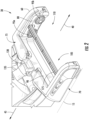
FIG. 2 is a perspective view of the base ofFIG. 1 with brush rolls removed from the base. -
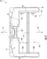
FIG. 3 is a top view of the base ofFIG. 2 . -
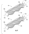
FIG. 4 is a perspective view of brush rolls of the surface cleaning extractor ofFIG. 1 . -
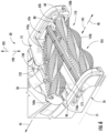
FIG. 5 is a perspective view of the base ofFIG. 1 illustrating a cover removed from the base allowing access to the brush rolls. -
FIG. 6 is a perspective view of the base ofFIG. 1 illustrating one brush roll being partially removed or partially inserted relative to the base and another brush roll coupled to the base. - Before any embodiments of the invention are explained in detail, it is to be understood that the invention is not limited in its application to the details of construction and the arrangement of components set forth in the following description or illustrated in the following drawings. The invention is capable of other embodiments and being practiced or being carried out in various ways. Also, it is to be understood that the phraseology and terminology used herein is for the purpose of description and should not be regarded as limiting. Terms of degree, such as "substantially," "about," "approximately," etc. are understood by those of ordinary skill to refer to reasonable ranges outside of the given value, for example, general tolerances associated with manufacturing, assembly, and use of the described embodiments.
- A surface cleaning extractor 10 (e.g., an upright-style carpet extractor) is illustrated in
FIG. 1 positioned on acleaning surface 15 and includes abody 20 having asuction motor 25 pivotably coupled to abase 30 between an upright or storage position (FIG. 1 ) and an inclined or operable position (not shown). Thebase 30 includes a fluid distributor 175 (FIG. 2 ) configured to dispense liquid onto thesurface 15 to be cleaned and at least afirst brush roll 65a operably disposed in thebase 30. Thefirst brush roll 65a is removable from thebase 30 through atop 75 of thebase 30 adjacent thefluid distributor 175. In other embodiments, theextractor 10 can be a portable handheld extractor or accessory, an upright-style vacuum cleaner with fluid distribution, a canister-style cleaner with fluid distribution, a power sweeper with fluid distribution, a hard floor cleaner, etc. For example, thebase 30 can be a handheld auxiliary attachment to theextractor 10. The illustratedbody 20 includes ahandle 35 operable by a user to push theextractor 10 in aforward direction 40 or pull theextractor 10 in arearward direction 45. Aliquid tank 50 is selectively coupled to thebody 20 or thebase 30 in communication with thefluid distributor 175 and holds a cleaning liquid (e.g., a mixture of water and cleaning solution). Also, arecovery tank 55 is selectively coupled to thebody 20 or thebase 30 and holds debris and dirty liquid collected by theextractor 10 from thecleaning surface 15 during operation. - With reference to
FIGS. 1 and2 , thebase 30 includes ahead 60 supporting thefirst brush roll 65a and asecond brush roll 65b. Thehead 60 includes abottom 70 that faces thecleaning surface 15 and thetop 75 opposite thebottom 70. Thehead 60 also includes afirst side wall 80, a second side wall 85 (FIG. 3 ) opposite thefirst side wall 80, and alateral wall 90 extending between the first andsecond side walls walls bottom 70 and thetop 75 of thehead 60.Drive protrusions first side wall 80 and are driven by an electric motor (not shown) coupled to thebase 30. With reference toFIG. 3 , supports 100a, 100b are located on thesecond side wall 85 each positioned opposite acorresponding drive protrusion drive protrusions supports second brush rolls base 30, as discussed in more detail below. The first andsecond side walls lateral wall 90 define acavity 105 of thebase 30. The illustratedbase 30 also includes afront opening 110 opposite thelateral wall 90. In other embodiments, thefront opening 110 can be replaced by a wall extending between the first andsecond side walls lateral wall 90. In addition, thebase 30 includes wheels (only onewheel 115 is shown inFIG. 1 ) that engage the cleaning surface 15 (e.g., carpet, hard wood floor, etc.) and enable movement of theextractor 10 in either theforward direction 40 or therearward direction 45. - With continued reference to
FIGS. 1 and2 , thebase 30 also includes a cover 120 (e.g., a transparent cover) selectively coupled to thebase 30 to cover thetop 75 of thebase 30 that defines a portion of thecavity 105 and thefront opening 110. Thecover 120 includes anozzle 125 in fluid communication with therecovery tank 55 by a passageway at least defined by aninlet 130 coupled to thetop 75 of thehead 60 and aflexible conduit 135 extending between theinlet 130 and thebody 20. With references toFIG. 5 , thenozzle 125 includes anozzle passageway 136 formed between anupper wall 137 of thenozzle 125 and alower wall 138 of thenozzle 125. Thenozzle passageway 136 extends from anozzle inlet 139 to anozzle outlet 141. Alatch 140 of thecover 120 engages theinlet 130 to secure thecover 120 to thebase 30 with thenozzle outlet 141 in communication with theinlet 130. In the illustrated embodiment, thecover 120 is completely disconnected from thebase 30 by releasing thelatch 140 from the inlet 130 (FIG. 5 ). In other embodiments, thecover 120 can remain coupled to thebase 30 and moveable (e.g., pivotable) between a closed or secured position and an open position. - With reference to
FIG. 4 , eachbrush roll deformable brush members brush roll body brush roll body recess corresponding drive protrusions base mount longitudinal axis recess base mount base mount corresponding supports brush roll body maximum dimension 170 measured perpendicular to its respectivelongitudinal axis base mount brush roll body brush roll body longitudinal axis corresponding base mount drive protrusions second brush rolls corresponding recesses first side wall 80 of thebase 30. In further embodiments,various base mounts supports brush rolls - As shown in
FIGS. 2 and3 , thefluid distributor 175 is positioned within thecavity 105 and extends between the first andsecond side walls head 60. Thefluid distributor 175 is spaced from thelateral wall 90 by afirst dimension 180 measured parallel to the forward andrearward directions fluid distributor 175 is fixedly coupled to thehead 60 and is in fluid communication with theliquid tank 50 to dispense the liquid within theliquid tank 50 onto thecleaning surface 15. In other embodiments, thefluid distributor 175 is removable from thebase 30. In one embodiment, a pressurized liquid delivery system is coupled to theliquid tank 50 and thefluid distributor 175 to dispense liquid through at least one nozzle of thefluid distributor 175 at a determined pressure. In other embodiments, a gravity-feed liquid delivery system is coupled to theliquid tank 50 and thefluid distributor 175 to dispense liquid through thefluid distributor 175 due to gravity. In further embodiments, thefluid distributor 175 can be positioned in the front opening 110 (e.g., in front of thesecond brush roll 65b) or coupled to the lateral wall 90 (e.g., behind thefirst brush roll 65a). In further embodiments, thebase 30 can include more than onefluid distributor 175. - With reference to
FIGS. 5 and6 , the brush rolls 65a, 65b are independently removable from the base 30 to facilitate cleaning of the brush rolls 65a, 65b. In particular, thecover 120 is disconnected from the base 30 by actuating thelatch 140 from the inlet 130 (FIG. 5 ). In other words, thecover 120 moves relative to thebase 30 and thefluid distributor 175 allowing physical access to the brush rolls 65a, 65b while thebase 30 is supported on thecleaning surface 15. For example, once thecover 120 is opened or removed, which also fluidly decouples thenozzle outlet 141 from theconduit 135, the user is able to touch the brush rolls 65a, 65b to inspect the brush rolls 65a, 65b and/or remove the brush rolls 65a, 65b from thebase 30. As such, thecover 120 is movable relative to the base 30 to open the top 75 of the base 30 allowing removal of the brush rolls 65a, 65b from the base 30 through the top 75 of the base 30 adjacent thefluid distributor 175. As shown inFIG. 6 , thefirst brush roll 65a is positioned between thefluid distributor 175 and thelateral wall 90 such that thefirst brush roll 65a moves past thefluid distributor 175 in an upwardvertical direction 185 as thefirst brush roll 65a is removed from thebase 30. Thevertical direction 185 is perpendicular to the forward andrearward directions vertical direction 185 can be obliquely oriented relative to thedirections cover 120 and thebrush roll cover 120 is disconnected. Also, thefluid distributor 175 is positioned on the base 30 as to not impede removal of the brush rolls 65a, 65b. Accordingly, thecover 120 and thefluid distributor 175 allow for easy access, removal, and cleaning of the brush rolls 65a, 65b while theextractor 10 is in the upright position (FIG. 1 ). - Once the brush rolls 65a, 65b are removed and cleaned, the brush rolls 65a, 65b are independently coupled to the
base 30. In particular, when thecover 120 is removed from thebase 30, thefirst brush roll 65a is insertable into thecavity 105 between thefluid distributor 175 and thelateral wall 90 in a downwardvertical direction 190 from the top 75 to the bottom 70 of thebase 30. The downwardvertical direction 190 is opposite theupward direction 185. In other embodiments, the downwardvertical direction 190 can be obliquely oriented relative to the forward andrearward directions first dimension 180 of thebase 30 is greater than themaximum dimension 170 of thefirst brush roll 65a allowing thefirst brush roll 65a to be inserted between thelateral wall 90 and thefluid distributor 175. In some embodiments, the firstdeformable brush members 145a can include a dimension greater than thefirst dimension 180 of the base 30 causing the firstdeformable brush members 145a to contact thelateral wall 90 and/or thefluid distributor 175 and deform while thefirst brush roll 65a is inserted into thecavity 105. In the illustrated embodiment, thefirst recess 155a receives thefirst drive protrusion 95a to provide a pivot point for thefirst brush roll 65a to then pivot thefirst base mount 160a into engagement with thefirst support 100a. The engagement between thefirst base mount 160a and thefirst support 100a can be a snap fit engagement, or the like, to hold thefirst brush roll 65a to thebase 30. Accordingly, thefirst drive protrusion 95a is operable to drive thefirst brush roll 65a about a first rotational axis concentric with itslongitudinal axis 165a while thefirst support 100a and thefirst base mount 160a support rotational movement of thefirst brush roll 65a. - The
second brush roll 65b can be coupled to the base 30 in a similar manner as thefirst brush roll 65a. When thecover 120 is removed from thebase 30, thesecond brush roll 65b is inserted into thecavity 105 between thefluid distributor 175 and thefront opening 110 in thedownward direction 190. Thesecond brush roll 65b can also be coupled to thebase 30 by inserting thesecond brush roll 65b through thefront opening 110 in a rearwardhorizontal direction 195 perpendicular to the downward direction 190 (e.g., parallel to the rearward direction 45). In other embodiments, thesecond brush roll 65b can be inserted into thecavity 105 at any angle between thedownward direction 190 and thehorizontal direction 195. In the illustrated embodiment, thesecond recess 155b receives thesecond drive protrusion 95b to provide a pivot point for thesecond brush roll 65b to then pivot thesecond base mount 160b into engagement with thesecond support 100b. The engagement between thesecond base mount 160b and thesecond support 100b can be a snap fit engagement, or the like, to hold thesecond brush roll 65b to thebase 30. Accordingly, thesecond drive protrusion 95b is operable to drive thesecond brush roll 65b about a second rotational axis concentric with itslongitudinal axis 165b while thesecond support 100b and thesecond base mount 160b support rotational movement of thesecond brush roll 65b. In one embodiment, the steps to couple the first and second brush rolls 65a, 65b to the base 30 are reversed to remove the first and second brush rolls 65a, 65b from thebase 30. - With reference back to
FIG. 1 , thecover 120 is coupled to thebase 30 by actuating thelatch 140 on theinlet 130, thus blocking access to the brush rolls 65a, 65b as thebase 30 is supported on thesurface 15. In the embodiments where thefluid distributor 175 is releasable from thebase 30, thefluid distributor 175 is manually coupled to thebase 30 by the user before thecover 120 is coupled to thebase 30. In other embodiments, thefluid distributor 175 is coupled to the base 30 in response to thecover 120 being coupled to thebase 30. Once thecover 120 is coupled to thebase 30, theextractor 10 is operable to collect debris from the cleaningsurface 15. In particular, thesuction motor 25 provides an airflow from thenozzle inlet 139 through thenozzle passageway 136 and theconduit 135 to therecovery tank 55 to draw debris into therecovery tank 55. The brush rolls 65a, 65b are driven about theirrotational axes cleaning surface 15 to loosen debris that is attached to or embedded in thecleaning surface 15 allowing the airflow to more easily collect the debris. The cleaning liquid within theliquid tank 50 is selectively applied to thecleaning surface 15 by thefluid distributor 175 to help further loosen the debris and clean thesurface 15. Thefluid distributor 175 is positioned between the brush rolls 65a, 65b such that the cleaning liquid is dispensed between the brush rolls 65a, 65b. In addition, thefluid distributor 175 is positioned above therotational axes upward direction 185, thus in some embodiments, some of the cleaning liquid is dispensed directly onto the brush rolls 65a, 65b (e.g., to help clean the brush rolls 65a, 65b during operation).
Claims (12)
- An extractor (10) comprising:a body (20);a recovery tank (55) coupled to the body (20);a liquid tank (50) coupled to the body (20), the liquid tank (50) configured to hold a liquid;a base (30) pivotably coupled to the body (20) and configured to support the body (20) above a cleaning surface, the base (30) configured to be moved in a forward direction and a rearward direction along the cleaning surface, the base (30) including:a first side wall (80) extending along the forward direction,a second side wall (85) opposite the first side wall (80), the second side wall (85) extending along the forward direction, anda lateral wall (90) extending between the first side wall (80) and the second side wall (85);a fluid distributor (175) coupled to the base (30) and spaced from the lateral wall (90) in the forward direction, the fluid distributor (175) in fluid communication with the liquid tank (50) and configured to dispense the liquid from the liquid tank (50) onto the cleaning surface;a brush roll (65a, 65b) removably coupled to the base (30) and insertable into a cavity (105) between the fluid distributor (175), the first side wall (80), the second side wall (85), and the lateral wall (90) in a downward vertical direction (190); anda nozzle (125) in fluid communication with the recovery tank (55), the nozzle (125) coupled to the base (30) to block access to the brush roll (65a, 65b), the nozzle (125) moveable relative to the base (30) and the fluid distributor (175) allowing access to the brush roll (65a, 65b) and enabling removal of the brush roll (65a, 65b) from the base (30) while the fluid distributor (175) is coupled to the base (30).
- The extractor (10) of claim 1, wherein the fluid distributor (175) is fixed to the base (30).
- The extractor (10) of claim 1, wherein the fluid distributor (175) is releasably coupled to the base (30).
- The extractor (10) of claim 3, wherein the fluid distributor (175) is releasable from the base (30) as the nozzle (125) moves relative to the base (30).
- The extractor (10) according to any of the preceding claims, wherein the nozzle (125) disconnects from the base (30) allowing access to the brush roll (65a, 65b).
- The extractor (10) according to any of the preceding claims, wherein the nozzle (125) is movable relative to the base (30) to open a top (75) of the base (30), and wherein the brush roll (65a, 65b) is removable from the base (30) through the top (75) of the base (30).
- The extractor (10) of claim 6, wherein the brush roll (65a, 65b) is positioned between the fluid distributor (175) and a portion of the base (30) such that the brush roll (65a, 65b) moves past the fluid distributor (175) as the brush roll (65a, 65b) is removed from the base (30).
- The extractor (10) of claim 1, wherein the base (30) includes a top (75) opposite a bottom (70), wherein the bottom (70) is configured to face the cleaning surface, and wherein the brush roll (65a, 65b) is coupled to the base (30) by inserting the brush roll (65a, 65b) into the cavity (105) in a direction from the top (75) toward the bottom (70).
- The extractor (10) of claim 8, wherein the brush roll (65a, 65b) is driven about a rotational axis and includes a plurality of deformable brush members (145a, 145b) coupled to a brush roll body (150a, 150b), wherein a first dimension (180) is measured in a direction perpendicular to the rotational axis between the lateral wall (90) and the fluid distributor (175), and wherein the first dimension (180) is greater than a maximum dimension (170) of the brush roll body (150a, 150b) measured parallel to the first dimension (180).
- The extractor (10) according to any of the preceding claims, wherein the brush roll (65a, 65b) is driven about a rotational axis, and wherein the brush roll (65a, 65b) is coupled to the base (30) for the rotational axis to be positioned behind the fluid distributor (175) in a forward direction of travel of the extractor (10).
- The extractor (10) of claim 10, wherein the brush roll (65a, 65b) is a first brush roll (65a) and the rotational axis is a first rotational axis, wherein the extractor (10) includes a second brush roll (65b) removably coupled to the base (30), wherein the second brush roll (65b) is driven about a second rotational axis, and wherein the second brush roll (65b) is coupled to the base (30) for the second rotational axis to be positioned forward of the fluid distributor (175) in the forward direction of travel of the extractor (10).
- The extractor (10) of claim 11, wherein the base (30) includes a top (75) opposite a bottom (70), wherein the bottom (70) is configured to face the cleaning surface, wherein the first brush roll (65a) is coupled to the base (30) by inserting the first brush roll (65a) in a vertical direction (190) from the top (75) toward the bottom (70), wherein the base (30) includes a front opening (110), and wherein the second brush roll (65b) is coupled to the base (30) by inserting the second brush roll (65b) in the vertical direction (190) or a horizontal direction (195) perpendicular to the vertical direction (190) through the front opening (110).
Applications Claiming Priority (2)
| Application Number | Priority Date | Filing Date | Title |
|---|---|---|---|
| US201962928689P | 2019-10-31 | 2019-10-31 | |
| PCT/US2020/057943 WO2021087102A1 (en) | 2019-10-31 | 2020-10-29 | Surface cleaning extractor |
Publications (2)
| Publication Number | Publication Date |
|---|---|
| EP4051076A1 EP4051076A1 (en) | 2022-09-07 |
| EP4051076B1 true EP4051076B1 (en) | 2025-02-26 |
Family
ID=73646417
Family Applications (1)
| Application Number | Title | Priority Date | Filing Date |
|---|---|---|---|
| EP20816662.9A Active EP4051076B1 (en) | 2019-10-31 | 2020-10-29 | Surface cleaning extractor |
Country Status (7)
| Country | Link |
|---|---|
| US (1) | US20210127935A1 (en) |
| EP (1) | EP4051076B1 (en) |
| JP (1) | JP2023500478A (en) |
| KR (1) | KR20220071969A (en) |
| CN (1) | CN114641230A (en) |
| AU (1) | AU2020375829A1 (en) |
| WO (1) | WO2021087102A1 (en) |
Families Citing this family (4)
| Publication number | Priority date | Publication date | Assignee | Title |
|---|---|---|---|---|
| EP4059396A1 (en) * | 2021-03-17 | 2022-09-21 | Koninklijke Philips N.V. | Cleaning head for a wet vacuum cleaner |
| CN116158692A (en) * | 2022-12-23 | 2023-05-26 | 苏州聚邦电器有限公司 | Vacuum attachment |
| CN116998954A (en) * | 2022-12-30 | 2023-11-07 | 北京石头世纪科技股份有限公司 | Automatic cleaning equipment |
| AU2024201730B2 (en) * | 2023-03-27 | 2026-02-05 | Techtronic Floor Care Technology Limited | Surface cleaner |
Family Cites Families (7)
| Publication number | Priority date | Publication date | Assignee | Title |
|---|---|---|---|---|
| US5323510A (en) * | 1993-07-09 | 1994-06-28 | Redding Glenn K | Vacuum cleaner having improved steering features |
| US6533871B2 (en) * | 2001-01-12 | 2003-03-18 | Royal Appliance Mfg. Co. | Carpet extractor with dual nozzles for dual brushrolls |
| US7979952B2 (en) * | 2006-12-13 | 2011-07-19 | Ab Electrolux | Wet/dry floor cleaning device |
| AU2016101525A4 (en) * | 2015-09-14 | 2016-09-29 | Bissell Inc. | Surface cleaning apparatus |
| US10702108B2 (en) * | 2015-09-28 | 2020-07-07 | Sharkninja Operating Llc | Surface cleaning head for vacuum cleaner |
| CN208510945U (en) * | 2017-10-31 | 2019-02-19 | 苏州德莱电器有限公司 | A kind of floor surface washing machine |
| US11219347B2 (en) * | 2017-12-22 | 2022-01-11 | Bissell Inc. | Robotic cleaner |
-
2020
- 2020-10-29 EP EP20816662.9A patent/EP4051076B1/en active Active
- 2020-10-29 AU AU2020375829A patent/AU2020375829A1/en not_active Abandoned
- 2020-10-29 WO PCT/US2020/057943 patent/WO2021087102A1/en not_active Ceased
- 2020-10-29 KR KR1020227014344A patent/KR20220071969A/en not_active Abandoned
- 2020-10-29 CN CN202080074890.4A patent/CN114641230A/en active Pending
- 2020-10-29 JP JP2022525085A patent/JP2023500478A/en active Pending
- 2020-10-29 US US17/083,982 patent/US20210127935A1/en not_active Abandoned
Also Published As
| Publication number | Publication date |
|---|---|
| JP2023500478A (en) | 2023-01-06 |
| KR20220071969A (en) | 2022-05-31 |
| WO2021087102A1 (en) | 2021-05-06 |
| CN114641230A (en) | 2022-06-17 |
| AU2020375829A1 (en) | 2022-04-21 |
| US20210127935A1 (en) | 2021-05-06 |
| EP4051076A1 (en) | 2022-09-07 |
Similar Documents
| Publication | Publication Date | Title |
|---|---|---|
| AU2020375829A1 (en) | Surface cleaning extractor | |
| JP3230037U (en) | Surface cleaning device that performs two-stage collection | |
| JP2021151470A (en) | Surface cleaning apparatus and tray | |
| US5611106A (en) | Carpet maintainer | |
| US20060236494A1 (en) | Hard and soft floor surface cleaner | |
| US20210161349A1 (en) | Floor cleaner having a removable nozzle | |
| US20130047353A1 (en) | Floor cleaning tool and method | |
| JPH02255118A (en) | Floor cleaner | |
| EP2063756A1 (en) | Battery powered extractor | |
| CN215605455U (en) | Cordless floor cleaning machine | |
| US6125499A (en) | High flow steam carpet cleaner | |
| JP2023500481A (en) | brush roll for floor cleaner | |
| EP4307975B1 (en) | Supplying liquid to at least one area of a surface to be cleaned | |
| US20240148205A1 (en) | Supplying liquid to at least one wheel of a suction head | |
| EP4364629A1 (en) | Cleaning apparatus | |
| CN115349784A (en) | Surface cleaning device and surface cleaning equipment | |
| US20240415356A1 (en) | Floor treatment machine | |
| US20250221592A1 (en) | Surface cleaning apparatus including a removable brushroll drive train | |
| JP2021104341A (en) | Surface cleaning apparatus and tray | |
| CN217659635U (en) | Cleaning device | |
| US20240156311A1 (en) | Suction head for application in a vacuum cleaner | |
| JPH0642592Y2 (en) | Vacuum cleaner cleaning device | |
| CN209808205U (en) | Dirty liquid recovery subassembly and surface cleaning equipment | |
| CN113925404B (en) | Cleaning base and surface cleaning device | |
| CN115530689B (en) | Floor cleaning equipment |
Legal Events
| Date | Code | Title | Description |
|---|---|---|---|
| STAA | Information on the status of an ep patent application or granted ep patent |
Free format text: STATUS: UNKNOWN |
|
| STAA | Information on the status of an ep patent application or granted ep patent |
Free format text: STATUS: THE INTERNATIONAL PUBLICATION HAS BEEN MADE |
|
| PUAI | Public reference made under article 153(3) epc to a published international application that has entered the european phase |
Free format text: ORIGINAL CODE: 0009012 |
|
| STAA | Information on the status of an ep patent application or granted ep patent |
Free format text: STATUS: REQUEST FOR EXAMINATION WAS MADE |
|
| 17P | Request for examination filed |
Effective date: 20220421 |
|
| AK | Designated contracting states |
Kind code of ref document: A1 Designated state(s): AL AT BE BG CH CY CZ DE DK EE ES FI FR GB GR HR HU IE IS IT LI LT LU LV MC MK MT NL NO PL PT RO RS SE SI SK SM TR |
|
| DAV | Request for validation of the european patent (deleted) | ||
| DAX | Request for extension of the european patent (deleted) | ||
| RAP1 | Party data changed (applicant data changed or rights of an application transferred) |
Owner name: TECHTRONIC FLOOR CARE TECHNOLOGY LIMITED |
|
| GRAP | Despatch of communication of intention to grant a patent |
Free format text: ORIGINAL CODE: EPIDOSNIGR1 |
|
| STAA | Information on the status of an ep patent application or granted ep patent |
Free format text: STATUS: GRANT OF PATENT IS INTENDED |
|
| INTG | Intention to grant announced |
Effective date: 20241203 |
|
| GRAS | Grant fee paid |
Free format text: ORIGINAL CODE: EPIDOSNIGR3 |
|
| GRAA | (expected) grant |
Free format text: ORIGINAL CODE: 0009210 |
|
| STAA | Information on the status of an ep patent application or granted ep patent |
Free format text: STATUS: THE PATENT HAS BEEN GRANTED |
|
| P01 | Opt-out of the competence of the unified patent court (upc) registered |
Free format text: CASE NUMBER: APP_840/2025 Effective date: 20250108 |
|
| AK | Designated contracting states |
Kind code of ref document: B1 Designated state(s): AL AT BE BG CH CY CZ DE DK EE ES FI FR GB GR HR HU IE IS IT LI LT LU LV MC MK MT NL NO PL PT RO RS SE SI SK SM TR |
|
| REG | Reference to a national code |
Ref country code: GB Ref legal event code: FG4D |
|
| REG | Reference to a national code |
Ref country code: CH Ref legal event code: EP |
|
| REG | Reference to a national code |
Ref country code: DE Ref legal event code: R096 Ref document number: 602020046875 Country of ref document: DE |
|
| REG | Reference to a national code |
Ref country code: IE Ref legal event code: FG4D |
|
| REG | Reference to a national code |
Ref country code: NL Ref legal event code: MP Effective date: 20250226 |
|
| PG25 | Lapsed in a contracting state [announced via postgrant information from national office to epo] |
Ref country code: RS Free format text: LAPSE BECAUSE OF FAILURE TO SUBMIT A TRANSLATION OF THE DESCRIPTION OR TO PAY THE FEE WITHIN THE PRESCRIBED TIME-LIMIT Effective date: 20250526 |
|
| PG25 | Lapsed in a contracting state [announced via postgrant information from national office to epo] |
Ref country code: FI Free format text: LAPSE BECAUSE OF FAILURE TO SUBMIT A TRANSLATION OF THE DESCRIPTION OR TO PAY THE FEE WITHIN THE PRESCRIBED TIME-LIMIT Effective date: 20250226 |
|
| PG25 | Lapsed in a contracting state [announced via postgrant information from national office to epo] |
Ref country code: PL Free format text: LAPSE BECAUSE OF FAILURE TO SUBMIT A TRANSLATION OF THE DESCRIPTION OR TO PAY THE FEE WITHIN THE PRESCRIBED TIME-LIMIT Effective date: 20250226 |
|
| PG25 | Lapsed in a contracting state [announced via postgrant information from national office to epo] |
Ref country code: ES Free format text: LAPSE BECAUSE OF FAILURE TO SUBMIT A TRANSLATION OF THE DESCRIPTION OR TO PAY THE FEE WITHIN THE PRESCRIBED TIME-LIMIT Effective date: 20250226 |
|
| REG | Reference to a national code |
Ref country code: LT Ref legal event code: MG9D |
|
| PG25 | Lapsed in a contracting state [announced via postgrant information from national office to epo] |
Ref country code: NO Free format text: LAPSE BECAUSE OF FAILURE TO SUBMIT A TRANSLATION OF THE DESCRIPTION OR TO PAY THE FEE WITHIN THE PRESCRIBED TIME-LIMIT Effective date: 20250526 Ref country code: IS Free format text: LAPSE BECAUSE OF FAILURE TO SUBMIT A TRANSLATION OF THE DESCRIPTION OR TO PAY THE FEE WITHIN THE PRESCRIBED TIME-LIMIT Effective date: 20250626 |
|
| PG25 | Lapsed in a contracting state [announced via postgrant information from national office to epo] |
Ref country code: NL Free format text: LAPSE BECAUSE OF FAILURE TO SUBMIT A TRANSLATION OF THE DESCRIPTION OR TO PAY THE FEE WITHIN THE PRESCRIBED TIME-LIMIT Effective date: 20250226 |
|
| PG25 | Lapsed in a contracting state [announced via postgrant information from national office to epo] |
Ref country code: HR Free format text: LAPSE BECAUSE OF FAILURE TO SUBMIT A TRANSLATION OF THE DESCRIPTION OR TO PAY THE FEE WITHIN THE PRESCRIBED TIME-LIMIT Effective date: 20250226 |
|
| PG25 | Lapsed in a contracting state [announced via postgrant information from national office to epo] |
Ref country code: LV Free format text: LAPSE BECAUSE OF FAILURE TO SUBMIT A TRANSLATION OF THE DESCRIPTION OR TO PAY THE FEE WITHIN THE PRESCRIBED TIME-LIMIT Effective date: 20250226 Ref country code: PT Free format text: LAPSE BECAUSE OF FAILURE TO SUBMIT A TRANSLATION OF THE DESCRIPTION OR TO PAY THE FEE WITHIN THE PRESCRIBED TIME-LIMIT Effective date: 20250626 |
|
| PG25 | Lapsed in a contracting state [announced via postgrant information from national office to epo] |
Ref country code: BG Free format text: LAPSE BECAUSE OF FAILURE TO SUBMIT A TRANSLATION OF THE DESCRIPTION OR TO PAY THE FEE WITHIN THE PRESCRIBED TIME-LIMIT Effective date: 20250226 Ref country code: GR Free format text: LAPSE BECAUSE OF FAILURE TO SUBMIT A TRANSLATION OF THE DESCRIPTION OR TO PAY THE FEE WITHIN THE PRESCRIBED TIME-LIMIT Effective date: 20250527 |
|
| REG | Reference to a national code |
Ref country code: AT Ref legal event code: MK05 Ref document number: 1769794 Country of ref document: AT Kind code of ref document: T Effective date: 20250226 |
|
| PG25 | Lapsed in a contracting state [announced via postgrant information from national office to epo] |
Ref country code: SE Free format text: LAPSE BECAUSE OF FAILURE TO SUBMIT A TRANSLATION OF THE DESCRIPTION OR TO PAY THE FEE WITHIN THE PRESCRIBED TIME-LIMIT Effective date: 20250226 |
|
| PG25 | Lapsed in a contracting state [announced via postgrant information from national office to epo] |
Ref country code: SM Free format text: LAPSE BECAUSE OF FAILURE TO SUBMIT A TRANSLATION OF THE DESCRIPTION OR TO PAY THE FEE WITHIN THE PRESCRIBED TIME-LIMIT Effective date: 20250226 |
|
| PG25 | Lapsed in a contracting state [announced via postgrant information from national office to epo] |
Ref country code: DK Free format text: LAPSE BECAUSE OF FAILURE TO SUBMIT A TRANSLATION OF THE DESCRIPTION OR TO PAY THE FEE WITHIN THE PRESCRIBED TIME-LIMIT Effective date: 20250226 |
|
| PG25 | Lapsed in a contracting state [announced via postgrant information from national office to epo] |
Ref country code: IT Free format text: LAPSE BECAUSE OF FAILURE TO SUBMIT A TRANSLATION OF THE DESCRIPTION OR TO PAY THE FEE WITHIN THE PRESCRIBED TIME-LIMIT Effective date: 20250226 |
|
| PG25 | Lapsed in a contracting state [announced via postgrant information from national office to epo] |
Ref country code: AT Free format text: LAPSE BECAUSE OF FAILURE TO SUBMIT A TRANSLATION OF THE DESCRIPTION OR TO PAY THE FEE WITHIN THE PRESCRIBED TIME-LIMIT Effective date: 20250226 |
|
| PG25 | Lapsed in a contracting state [announced via postgrant information from national office to epo] |
Ref country code: CZ Free format text: LAPSE BECAUSE OF FAILURE TO SUBMIT A TRANSLATION OF THE DESCRIPTION OR TO PAY THE FEE WITHIN THE PRESCRIBED TIME-LIMIT Effective date: 20250226 Ref country code: EE Free format text: LAPSE BECAUSE OF FAILURE TO SUBMIT A TRANSLATION OF THE DESCRIPTION OR TO PAY THE FEE WITHIN THE PRESCRIBED TIME-LIMIT Effective date: 20250226 |
|
| PG25 | Lapsed in a contracting state [announced via postgrant information from national office to epo] |
Ref country code: RO Free format text: LAPSE BECAUSE OF FAILURE TO SUBMIT A TRANSLATION OF THE DESCRIPTION OR TO PAY THE FEE WITHIN THE PRESCRIBED TIME-LIMIT Effective date: 20250226 |
|
| PG25 | Lapsed in a contracting state [announced via postgrant information from national office to epo] |
Ref country code: SK Free format text: LAPSE BECAUSE OF FAILURE TO SUBMIT A TRANSLATION OF THE DESCRIPTION OR TO PAY THE FEE WITHIN THE PRESCRIBED TIME-LIMIT Effective date: 20250226 |
|
| REG | Reference to a national code |
Ref country code: DE Ref legal event code: R097 Ref document number: 602020046875 Country of ref document: DE |
|
| PLBE | No opposition filed within time limit |
Free format text: ORIGINAL CODE: 0009261 |
|
| STAA | Information on the status of an ep patent application or granted ep patent |
Free format text: STATUS: NO OPPOSITION FILED WITHIN TIME LIMIT |
|
| PGFP | Annual fee paid to national office [announced via postgrant information from national office to epo] |
Ref country code: DE Payment date: 20251029 Year of fee payment: 6 |
|
| PGFP | Annual fee paid to national office [announced via postgrant information from national office to epo] |
Ref country code: GB Payment date: 20251027 Year of fee payment: 6 |
|
| PGFP | Annual fee paid to national office [announced via postgrant information from national office to epo] |
Ref country code: FR Payment date: 20251027 Year of fee payment: 6 |
|
| 26N | No opposition filed |
Effective date: 20251127 |