EP4050285B1 - Doppelreihiger fasseisbereiter mit kopfabsaugung - Google Patents
Doppelreihiger fasseisbereiter mit kopfabsaugung Download PDFInfo
- Publication number
- EP4050285B1 EP4050285B1 EP22167258.7A EP22167258A EP4050285B1 EP 4050285 B1 EP4050285 B1 EP 4050285B1 EP 22167258 A EP22167258 A EP 22167258A EP 4050285 B1 EP4050285 B1 EP 4050285B1
- Authority
- EP
- European Patent Office
- Prior art keywords
- mold cavities
- row
- ice
- mold
- ice maker
- Prior art date
- Legal status (The legal status is an assumption and is not a legal conclusion. Google has not performed a legal analysis and makes no representation as to the accuracy of the status listed.)
- Active
Links
Images




Classifications
-
- F—MECHANICAL ENGINEERING; LIGHTING; HEATING; WEAPONS; BLASTING
- F25—REFRIGERATION OR COOLING; COMBINED HEATING AND REFRIGERATION SYSTEMS; HEAT PUMP SYSTEMS; MANUFACTURE OR STORAGE OF ICE; LIQUEFACTION SOLIDIFICATION OF GASES
- F25C—PRODUCING, WORKING OR HANDLING ICE
- F25C5/00—Working or handling ice
- F25C5/02—Apparatus for disintegrating, removing or harvesting ice
- F25C5/04—Apparatus for disintegrating, removing or harvesting ice without the use of saws
-
- F—MECHANICAL ENGINEERING; LIGHTING; HEATING; WEAPONS; BLASTING
- F25—REFRIGERATION OR COOLING; COMBINED HEATING AND REFRIGERATION SYSTEMS; HEAT PUMP SYSTEMS; MANUFACTURE OR STORAGE OF ICE; LIQUEFACTION SOLIDIFICATION OF GASES
- F25C—PRODUCING, WORKING OR HANDLING ICE
- F25C1/00—Producing ice
- F25C1/04—Producing ice by using stationary moulds
-
- F—MECHANICAL ENGINEERING; LIGHTING; HEATING; WEAPONS; BLASTING
- F25—REFRIGERATION OR COOLING; COMBINED HEATING AND REFRIGERATION SYSTEMS; HEAT PUMP SYSTEMS; MANUFACTURE OR STORAGE OF ICE; LIQUEFACTION SOLIDIFICATION OF GASES
- F25C—PRODUCING, WORKING OR HANDLING ICE
- F25C1/00—Producing ice
- F25C1/22—Construction of moulds; Filling devices for moulds
- F25C1/24—Construction of moulds; Filling devices for moulds for refrigerators, e.g. freezing trays
-
- F—MECHANICAL ENGINEERING; LIGHTING; HEATING; WEAPONS; BLASTING
- F25—REFRIGERATION OR COOLING; COMBINED HEATING AND REFRIGERATION SYSTEMS; HEAT PUMP SYSTEMS; MANUFACTURE OR STORAGE OF ICE; LIQUEFACTION SOLIDIFICATION OF GASES
- F25C—PRODUCING, WORKING OR HANDLING ICE
- F25C5/00—Working or handling ice
- F25C5/02—Apparatus for disintegrating, removing or harvesting ice
-
- F—MECHANICAL ENGINEERING; LIGHTING; HEATING; WEAPONS; BLASTING
- F25—REFRIGERATION OR COOLING; COMBINED HEATING AND REFRIGERATION SYSTEMS; HEAT PUMP SYSTEMS; MANUFACTURE OR STORAGE OF ICE; LIQUEFACTION SOLIDIFICATION OF GASES
- F25C—PRODUCING, WORKING OR HANDLING ICE
- F25C2400/00—Auxiliary features or devices for producing, working or handling ice
- F25C2400/06—Multiple ice moulds or trays therefor
Definitions
- the present subject matter relates generally to ice makers, and in particular to ice makers for forming barrel ice.
- Certain refrigerator appliances include an ice maker.
- An ice maker may also be a stand-alone appliance designed for use in commercial and/or residential kitchens.
- To produce ice liquid water is directed to the ice maker and frozen.
- a variety of ice types can be produced depending upon the particular ice maker used.
- certain ice makers include a mold body for receiving liquid water.
- the shape of the ice produced in such ice makers will generally correspond to the shape of the mold body.
- refrigerator ice makers and other residential ice makers commonly include a mold body which produces crescent-shaped ice.
- barrel ice which may be generally cylindrical in shape, over crescent-shaped ice pieces.
- Past attempts at providing an ice maker which produces barrel-shaped ice have met with difficulty.
- some ice makers include a mold body with cylindrical mold cavities, where ice is harvested from the mold cavities by pushing the ice up out of the cavities from below, such as with a piston that passes through the bottom of at least one of the mold cavities.
- Such ice makers include a seal at the location(s) where the piston passes through the bottom of the mold cavity to prevent liquid water escaping the mold body. The movement of the piston may cause such seals to wear out prematurely.
- US 3 690 120 A discloses an ice maker comprising a mold containing a plurality of longitudinally spaced cavities connected by vertical passages and a vertically movable ejection means including a member extending through the passages.
- the ejection means includes upwardly extending dividers substantially filling the passages when the ejection means is in its normal or lower position to limit the formation of ice in the passages.
- the icemaker includes an ice tray rotatable with at least one column of ice making chambers formed therein to make ice, an ejector rotatably provided in each ice making chamber to eject the ice formed in the ice making chamber, an operation device which rotates the ice tray, and a separation device which separates the ice from the ice tray.
- the separation device may be a heater which heats the ice.
- an ice maker with features for producing and reliably harvesting barrel-shaped ice would be useful.
- terms of approximation such as “generally,” “about,” or “approximately” include values within ten percent greater or less than the stated value.
- such terms include within ten degrees greater or less than the stated angle or direction, e.g., "generally vertical” includes forming an angle of up to ten degrees in any direction, e.g., clockwise or counterclockwise, with the vertical direction V.
- Refrigerator appliance 100 includes a cabinet or housing 120 that generally defines a vertical direction V, a lateral direction L, and a transverse direction T, each of which is mutually perpendicular, such that an orthogonal coordinate system is generally defined.
- the cabinet 120 extends between a top 101 and a bottom 102 along the vertical direction V, between a left side 104 and a right side 106 along the lateral direction L, and between a front 108 and a rear 110 along the transverse direction T.
- Housing 120 defines chilled chambers for receipt of food items for storage.
- housing 120 defines fresh food chamber 122 positioned at or adjacent top 101 of housing 120 and a freezer chamber 124 arranged at or adjacent bottom 102 of housing 120.
- refrigerator appliance 100 is generally referred to as a bottom mount refrigerator. It is recognized, however, that the benefits of the present disclosure apply to other types and styles of refrigerator appliances such as, e.g., a top mount refrigerator appliance, a side-by-side style refrigerator appliance or a standalone ice maker appliance. Consequently, the description set forth herein is for illustrative purposes only and is not intended to be limiting in any aspect to any particular refrigerator chamber configuration.
- Refrigerator doors 128 are rotatably hinged to an edge of housing 120 for selectively accessing fresh food chamber 122, e.g., at the left side 104 and the right side 106.
- a freezer door 130 is arranged below refrigerator doors 128 for selectively accessing freezer chamber 124.
- Freezer door 130 is coupled to a freezer drawer (not shown) mounted within freezer chamber 124 and slidable along the transverse direction T. Refrigerator doors 128 and freezer door 130 are shown in the closed configuration in Fig. 1 .
- Refrigerator appliance 100 also includes a dispensing assembly 140 for dispensing liquid water and/or ice.
- Dispensing assembly 140 includes a dispenser 142 positioned on or mounted to an exterior portion of refrigerator appliance 100, e.g., on one of doors 128.
- Dispenser 142 includes a discharging outlet 144 for accessing ice and/or liquid water.
- An actuating mechanism 146 shown as a paddle, is mounted below discharging outlet 144 for operating dispenser 142.
- any suitable actuating mechanism may be used to operate dispenser 142.
- dispenser 142 can include a sensor (such as an ultrasonic sensor) or a button rather than the paddle.
- a user interface panel 148 is provided for controlling the mode of operation.
- user interface panel 148 includes a plurality of user inputs (not labeled), such as a water dispensing button and an ice-dispensing button, for selecting a desired mode of operation such as crushed or non-crushed ice.
- Discharging outlet 144 and actuating mechanism 146 are an external part of dispenser 142 and are mounted in a dispenser recess 150.
- Dispenser recess 150 is positioned at a predetermined elevation convenient for a user to access ice or water and enabling the user to access ice without the need to bend-over and without the need to open doors 128.
- dispenser recess 150 is positioned at a level that approximates the chest level of a user.
- Fig. 2 provides a perspective view of a door of refrigerator doors 128.
- Refrigerator appliance 100 includes a sub-compartment 162 defined on refrigerator door 128.
- Sub-compartment 162 may be referred to as an "icebox.”
- Sub-compartment 162 extends into fresh food chamber 122 when refrigerator door 128 is in the closed position.
- an ice maker or ice making assembly 160 and an ice storage bin 164 may be positioned or disposed within sub-compartment 162.
- dispenser recess 150 Fig. 1
- the ice maker 160 and/or ice storage bin 164 in sub-compartment 162 on a back side of refrigerator door 128.
- Chilled air from a sealed system (not shown) of refrigerator appliance 100 may be directed into components within sub-compartment 162, e.g., ice maker 160 and/or ice storage bin 164.
- sub-compartment 162 e.g., ice maker 160 and/or ice storage bin 164.
- present disclosure may also be applied to other types and styles of refrigerator appliances such as, e.g., a top mount refrigerator appliance, a side-by-side style refrigerator appliance or a standalone ice maker appliance. Accordingly, the description herein of the icebox 162 on the door 128 of the fresh food chamber 122 is by way of example only.
- the ice maker 160 may be positioned in the freezer chamber 124, e.g., of the illustrated bottom-mount refrigerator, a side by side refrigerator, a top-mount refrigerator, or any other suitable refrigerator appliance.
- the ice maker 160 may also be provided in a standalone icemaker appliance.
- An access door 166 is hinged to refrigerator door 128. Access door 166 permits selective access to sub-compartment 162. Any manner of suitable latch 168 is configured with sub-compartment 162 to maintain access door 166 in a closed position. As an example, latch 168 may be actuated by a consumer in order to open access door 166 for providing access into sub-compartment 162. Access door 166 can also assist with insulating sub-compartment 162, e.g., by thermally isolating or insulating sub-compartment 162 from fresh food chamber 122.
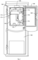
- Fig. 3 provides an elevation view of refrigerator door 128 with access door 166 shown in an open position.
- ice maker 160 is positioned or disposed within sub-compartment 162.
- Ice maker 160 includes a mold body or casing 170.
- a motor 174 is mounted within sub-compartment 162, and is in mechanical communication with (e.g., coupled to) an ejector assembly 180 ( Figs. 6 and 7 ) for ejecting ice from the mold body 170.
- An ice bucket or ice storage bin 164 is positioned proximate the mold body 170 and receives the ice after the ice is ejected from the mold body 170. From ice storage bin 164, the ice can enter dispensing assembly 140 and be accessed by a user as discussed above. In such a manner, ice maker 160 can produce or generate ice.
- Ice maker 160 also includes a fan 176.
- Fan 176 is configured for directing a flow of chilled air towards mold body 170.
- fan 176 can direct chilled air from an evaporator of a sealed system through a duct to mold body 170.
- mold body 170 can be cooled with chilled air from fan 176 such that ice maker 160 is air cooled in order to form ice therein.
- Ice maker 160 also includes a heater 175, such as an electric resistance heating element, mounted to or otherwise in thermal communication with mold body 170.
- Heater 175 is configured for selectively heating mold body 170, e.g., to assist in ejecting ice from the mold body 170.
- ice maker 160 Operation of ice maker 160 is controlled by a processing device or controller 190, e.g., that may be operatively coupled to control panel 148 for user manipulation to select features and operations of ice maker 160.
- Controller 190 can operate various components of ice maker 160 to execute selected system cycles and features.
- controller 190 is in operative communication with motor 174, fan 176 and heater 175.
- controller 190 can selectively activate and operate motor 174, fan 176 and heater 175.
- Controller 190 may include a memory and microprocessor, such as a general or special purpose microprocessor operable to execute programming instructions or micro-control code associated with operation of ice maker 160.
- the memory may represent random access memory such as DRAM, or read only memory such as ROM or FLASH.
- the processor executes programming instructions stored in memory.
- the memory may be a separate component from the processor or may be included onboard within the processor.
- controller 190 may be constructed without using a microprocessor, e.g., using a combination of discrete analog and/or digital logic circuitry (such as switches, amplifiers, integrators, comparators, flip-flops, AND gates, and the like) to perform control functionality instead of relying upon software.
- Motor 174, fan 176 and heater 175 may be in communication with controller 190 via one or more signal lines or shared communication busses.
- Ice maker 160 also includes a temperature sensor 178.
- Temperature sensor 178 is configured for measuring a temperature of mold body 170 and/or liquids, such as liquid water, within mold body 170.
- Temperature sensor 178 can be any suitable device for measuring the temperature of mold body 170 and/or liquids therein.
- temperature sensor 178 may be a thermistor or a thermocouple or a bimetal.
- Controller 190 can receive a signal, such as a voltage or a current, from temperature sensor 190 that corresponds to the temperature of the mold body 170 and/or liquids therein. In such a manner, the temperature of mold body 170 and/or liquids therein can be monitored and/or recorded with controller 190.
- Some embodiments can also include an electromechanical icemaker configured with a bimetal to complete an electrical circuit when a specific temperature is reached. By completion of the circuit, the heater 175 and ejector mechanism would be activated via electrical powering of the motor 174.
- Fig. 4 provides a perspective view of the ice maker 160 and Fig. 5 provides a similar view with some components not shown for clarity.
- the ice maker 160 defines a vertical direction VI, a lateral direction LI, and a transverse direction TI.
- the ice maker 160 is installed such that the vertical direction VI of the ice maker 160 generally corresponds to the vertical direction V of the cabinet 120.
- terms of approximation such as "generally” or “about” are used herein to include within ten percent greater or less than the stated value.
- angle or direction such terms include within ten degrees greater or less than the stated angle or direction.
- the ice maker 160 may be installed such that the vertical direction VI of the ice maker 160 generally corresponds to the vertical direction V of the cabinet 120 when the vertical direction VI is aligned with, or within ten degrees in any direction of, the vertical direction V.
- the mold body 170 of ice maker 160 includes a plurality of mold cavities 200 defined in the mold body 170 for forming ice 1000 therein.
- the mold body 170 includes six mold cavities 200. In other embodiments, more or fewer mold cavities 200 may be included.
- the plurality of mold cavities 200 include a first row 203 of mold cavities 200 extending generally along the transverse direction TI and a second row 205 of mold cavities 200 extending generally along the transverse direction TI and spaced apart from the first row 203 along the lateral direction LI.
- the mold cavities 200 may be configured to receive liquid water to form ice 1000 in each mold cavity 200.
- the shape of ice 1000 formed in the mold cavities 200 will correspond to the shape of the mold cavity 200.
- the mold cavities 200 may be generally cylindrical. Accordingly, generally cylindrical ice, sometimes referred to as "barrel ice,” may be produced by the ice maker 160, e.g., the ice 1000 may be ice barrels 1000.
- Example embodiments of the generally cylindrical mold cavity 200 may include tapered sidewalls, e.g., forming an angle of up to ten degrees with a floor 202 of the mold cavity 200, convex sidewalls, and/or concave sidewalls.
- the generally cylindrical mold cavity 200 may have any suitable cross-sectional shape, e.g., hexagonal, instead of a round, e.g., circular or oval, cross-section.
- the ice maker 160 includes an ejector assembly 180.
- the ejector assembly 180 includes a plurality of ejector pads 210.
- the plurality of ejector pads 210 correspond to the plurality of mold cavities 200, e.g., the plurality of ejector pads 210 include a first row 207 ( Fig. 9 ) of ejector pads 210 corresponding to the first row 203 of mold cavities 200 and a second row 209 ( Fig. 9 ) of ejector pads 210 corresponding to the second row 205 of mold cavities 200.
- the ejector assembly 180 may include six ejector pads 210.
- each ejector pad 210 is located within a corresponding mold cavity 200.
- each of the mold cavities 200 extends between a floor 202 and an opening 206 along a longitudinal axis A.
- each mold cavity 200 is enclosed between the floor 202 and the opening 206 by at least one sidewall 204.
- the sidewall 204 is generally cylindrical.
- the mold cavities 200 may be, e.g., hexagonal, and thus may include more than one, e.g., six, sidewalls 204 enclosing each mold cavity 200 between the floor 202 and the opening 204.
- each mold cavity 200 is oriented generally along the vertical direction VI of the ice maker 160, and may in some embodiments also be generally aligned with the vertical direction V of the refrigerator appliance 100.
- a recess 208 may be formed in the floor 202 of the mold cavity 200.
- an ejector pad 210 is provided in each mold cavity 200.
- the ejector pads 210 in each adjacent mold cavity 200 are connected together as part of the ejector assembly 180.
- the ejector assembly 180, and the plurality of ejector pads 210 thereof, are movable between a low position ( Fig. 6 ) proximate the floor 202 and a high position ( Fig. 7 ) proximate the opening 206.
- the ejector pads 210 may advantageously be rigidly secured to one another so that the ejector pads 210 move in unison between the low position and the high position.
- Each ejector pad 210 is configured to be received within the recess 208 in the floor 202 of the corresponding mold cavity 200 when the ejector assembly 180 is in the low position.
- the recess 208 may be circular and the ejector pad 210 may have a similar shape and size, e.g., circular and with a similar diameter, as the recess 208.
- the ejector assembly 180 is movable upward generally along the vertical direction VI from the low position to the high position.
- each ejector pad 210 is in or near the recess 208 in the floor 202 of each corresponding mold cavity 200 when the ejector assembly 180 is in the low position.
- the ejector pad 210 is proximate the opening 206 of the mold cavity 200. Accordingly, when ice 1000 ( Fig. 4 ) is formed within the mold cavity 200, moving the ejector pad 210 from the low position to the high position may eject the ice 1000 from the mold cavity 200, e.g., as shown in Fig. 4 .
- the motor 174 is in operative communication with the ejector assembly 180, such that the motor 174 is operable to move the plurality of ejector pads 210 generally along the vertical direction VI between the low position and the high position.
- the ice maker 160 may include a gear 182 which is engaged by a drive gear 181 of the motor 174 such that activating the motor 174 causes the gear 182 to rotate.
- the gear 182 is illustrated schematically in Figs. 4 , 6 , and 7 for the sake of clarity, the structure and operation of a gear is well understood by those of skill in the art.
- the gear 182 may be connected to a rotatable shaft 184 such that the rotatable shaft 184 rotates when the gear 182 rotates.
- Motor 174 is further in communication with the ejector assembly 180 via a cam 188 and a scotch yoke 192, as described in more detail below.
- the ice maker 160 includes an ice rake 216 positioned above the mold body 170 along the vertical direction VI.
- the ice rake 216 includes a rotatable shaft, e.g., the rotatable shaft 184 described above, and at least one rake finger 186 extending radially outward from the rotatable shaft 184.
- any suitable number of fingers 186 may be provided, e.g., the number of rake fingers 186 may correspond to the total number of mold cavities 200 in the plurality of mold cavities 200, or may correspond to the number of mold cavities 200 in one of the first row 203 and the second row 205.
- the ice rake 216 may include three rake fingers 186 where the plurality of mold cavities 200 includes six mold cavities 200 with three mold cavities 200 in the first row 203 and three mold cavities 200 in the second row 205, e.g., as shown in the example illustrated by Fig. 5 .
- the ejector pads 210 eject ice from each mold cavity 200 when the ejector assembly 180 moves from the low position to the high position.
- the ice rake 216 may be operable to dislodge the ice from the ejector pads 210 and/or mold cavity 200 and direct the ice towards the ice storage bin 164.
- the ice maker 160 may be configured, e.g., the fingers 186 of the ice rake 216 may be positioned on the rotatable shaft 184, such that the fingers 186 of the ice rake 216 pass over and close to the mold body 170 when the rotatable shaft 184 rotates to or towards the high position of the ejector assembly 180.
- the rake fingers 186 sweep over the mold cavities 200 in a direction towards the ice storage bin 164 to direct the ice from the mold body 170 towards the ice storage bin 164.
- the rake fingers 186 may define a path of rotation, e.g., as the rotatable shaft 184 rotates, the fingers 186 extending therefrom may travel through a generally circular path.
- the rake fingers 186 may be positioned and oriented on the rotatable shaft 184 such that the rake fingers 186 pass through a bottom point of the path of rotation with respect to the mold body 170 when the ejector assembly 180 is in or approaches the high position.
- the bottom point of the path of rotation may be the closest point of the rake fingers 186 to the mold body 170, e.g., where the rotatable shaft 184 is above the mold body 170. Accordingly, rotation of the rotatable shaft 184 may simultaneously eject ice upward out of the mold cavity 200 with the ejector assembly 180 and dislodge the ice from the mold body 170 and direct the ice into the ice storage bin 164 with the rake fingers 186.
- the ice maker 160 may be configured such that the rake fingers 186 initially contact the ice barrels 1000 of one of the first row 203 and the second row 205 as the rake fingers 186 approach the mold body 170.
- the rake fingers 186 may then dislodge the ice barrels 1000 of the one of the first row 203 and the second row 205 from the mold body 170, whereupon the rotatable shaft 184 continues to rotate and pushes the ice barrels 1000 of the one of the first row 203 and the second row 205 into the ice barrels 1000 of the other of the one of the first row 203 and the second row 205, thereby sweeping both rows of ice barrels 1000 towards the ice storage bin 164.
- a cam 188 may be formed on the gear 182 and thus the cam 188 may be connected to the rotatable shaft 184 via the gear 182.
- the ice maker 160 also includes a scotch yoke 192 which may have a slot 194 formed in the scotch yoke 192.
- the cam 188 may be received in the slot 194 of the scotch yoke 192, whereby rotation of the gear 182 is translated into reciprocating linear movement by the scotch yoke 192.
- the slot 194 may be arcuate, e.g., as illustrated in Fig.
- the speed of movement may be slightly biased so the ejector pad 210 will lift a little more slowly at the beginning of harvest as ice formed in the mold body 170 breaks loose from the mold body 170 and the cam 188 is close to six o'clock and the ejector pad 210 will lift faster when the cam 188 is closer to twelve o'clock.
- the motor 174 may be in operative communication with the ejector assembly 180 via the gear 182, the cam 188, and the rotatable shaft 184.
- the scotch yoke 192 may translate the rotation into upward linear movement along the vertical direction VI from the low position to the high position when the gear 184 rotates about one hundred eighty degrees (180°) and may translate the rotation into downward linear movement along the vertical direction VI from the high position to the low position when the gear 184 rotates an additional about one hundred eighty degrees (180°) to complete a revolution of the gear 184.
- the scotch yoke 192 is connected to the ejector assembly 180, whereby the linear movement along the vertical direction VI moves the ejector assembly, in particular the ejector pads 210 thereof, between the low position and the high position.
- two scotch yokes 192 may be provided, each connected to the ejector assembly 180 by a vertical rod 196.
- the vertical rod 196 may be telescopic such that the rod 196 extends as the ejector pad 210 moves from the low position to the high position and contracts as the ejector pad 210 moves from the high position to the low position.
- Each scotch yoke 192 may be provided at an opposite end of the rotatable shaft 184 in a similar fashion as the other scotch yoke 192.
- the rotatable shaft 184 may be held in position and structurally supported above the mold body 170 by a strut or wall 218.
- the wall 218 may extend vertically, e.g., generally along the vertical direction V and/or VI, between the mold body 170 and the rotatable shaft 184.
- a slot 220 may be formed in the wall 218 such that the ejector assembly 180 may pass through the wall 218.
- the slot 220 may define a vertical dimension, e.g., a height, sufficient to allow the ejector assembly 180 to move from the low position to the high position without interference from the wall 218.
- a second wall 218 may be provided which is identical to the wall 218 as described and shown.
- Fig. 8 schematically illustrates the position of the ice rake 216 relative to the mold body 170 and other components of the ice maker 160.
- the ejector pads 210 are shown in the high position and ice barrels 1000 ejected from the mold body 170 on the ejector pads 210 are shown in dashed lines.
- the rake fingers 186 when the rotatable shaft 184 rotates as described above, the rake fingers 186 extending therefrom travel along a circular path 215, e.g., clockwise as shown by arrow 250 in Fig. 8 .
- the rake fingers 186 rotate through and within a plane defined by the vertical direction VI and the lateral direction LI.
- the ice rake 216 in particular the rotatable shaft 184 thereof, may be offset, e.g., from a center 171 of the mold body 170.
- the mold body 170 may be generally symmetrical along the lateral direction LI, with each of the first row 203 and the second row 205 approximately equally spaced from the center 171 on opposite sides of the center 171.
- the rotatable shaft 184 may be offset from the center 171 by about one-half of the size, e.g., diameter, of one of the mold cavities 200.
- the rotatable shaft 184 may be positioned directly above the first row 203 of mold cavities 200 along the vertical direction VI, e.g., the rotatable shaft 184 may be positioned directly above or approximately directly above a center of the first row 203 of mold cavities 200.
- the ejector assembly 180 may include a first arm 211 connected to the first row 207 of ejector pads 210 at a first side 183 of the ejector assembly 180 and a second arm 212 connected the first row 207 of ejector pads 210 at a second side 185 of the ejector assembly 180. As shown, the second side 185 of the ejector assembly 180 is opposite the first side 183 of the ejector assembly 180.
- the ejector assembly 180 may also include a third arm 213 connected to the second row 209 of ejector pads 210 at the first side 183 of the ejector assembly 180 and a fourth arm 214 connected to the second row 209 of ejector pads 210 at the second side 185 of the ejector assembly 180.
- the arms 211, 212, 213, and 214 may be connected to the scotch yoke 192 and/or the vertical rod 196, and thus may form a part of the operative connection between the motor 174 and the ejector assembly 180.
- a plurality of notches 201 may be formed in the mold body 170 at opposite ends of each row 203, 205 of mold cavities 200, where the arms 211, 212, 213, and 214 can extend upward outside of the mold cavity 200 so as to avoid or minimize altering the shape of ice produced in the mold body 170 due to the presence of the arms 211, 212, 213, and 214.
- the mold cavities 200 of the first row 203 may be sized and/or positioned relative to the mold cavities 200 of the second row 205 to avoid or minimize ice barrels 1000 from the first row 203 falling into the mold cavities 200 of the second row 205 during ejection of the ice barrels 1000.
- the mold cavities 200 of the first row 203 may be sized and/or positioned relative to the mold cavities 200 of the second row 205 to avoid or minimize ice barrels 1000 from the first row 203 falling into the mold cavities 200 of the second row 205 during ejection of the ice barrels 1000.
- the mold cavities 200 in the first row 203 of mold cavities 200 may be offset from the mold cavities 200 in the second row 205 of mold cavities 200 along the transverse direction TI, e.g., such that the centers of the mold cavities 200 in each of the first row 203 and the second row 205 are not aligned with the centers of the mold cavities 200 in the other of the first row 203 and the second row 205.
- the mold cavities 200 in the first row 203 of mold cavities 200 may be the same size as the mold cavities 200 in the second row 205 of mold cavities 200, e.g., as illustrated in Fig. 9 . Fig.
- FIG. 10 illustrates an example of other embodiments wherein the mold cavities 200 in the first row 203 of mold cavities 200 are larger than the mold cavities 200 in the second row 205 of mold cavities 200.
- the mold cavities 200 in the first row 203 are larger than the mold cavities 200 in the second row 205
- ice barrels 1000 formed in the first row 203 of mold cavities 200 will be larger than the mold cavities 200 in the second row 205, whereby ice barrels 1000 formed in the first row 203 of mold cavities 200 are less likely to fall into the mold cavities 200 of the second row 205 during ejection.
- the rake fingers 186 are generally aligned along the circumference C of the rotatable shaft 184.
- the rake fingers 186 may only directly contact ice barrels 1000 formed in one of the first row 203 of mold cavities 200 and the second row 205 of mold cavities 200, e.g., where the total number of rake fingers 186 is the same as the number of mold cavities 200 in one of the first row 203 and the second row 205.
- additional rake fingers 186 may be provided which also extend radially from the rotatable shaft 184 and are spaced apart from the first group of rake fingers 186 along the circumference C ( Fig.
- the rotatable shaft 184 may include a radius R defining the radial direction, e.g., where the rake fingers 186 extend radially, as mentioned above, the rake fingers 186 extend generally along the radial direction.
- the rotatable shaft 184 may also include a circumference C and the additional rake fingers 186 may be spaced apart from the first group of rake fingers 186 along the circumference C by an angle ⁇ .
- the ice rake 216 may include a blade 228 extending radially outward from the rotatable shaft 184 and spaced apart from the rake fingers 186 along the circumference C of the rotatable shaft 184 by the angle ⁇ .
- the angle ⁇ may be between about thirty degrees and about ninety degrees, such as about sixty degrees, such as about forty-five degrees.
- the rake fingers 186 may be configured to contact ice barrels 1000 from one of the first row 203 of mold cavities 200 and the second row 205 of mold cavities 200
- the blade 228 may be configured to contact ice barrels 1000 from the other of the first row 203 of mold cavities 200 and the second row 205 of mold cavities 200.
- the ice rake 216 illustrated in Fig. 11 may be usable with the embodiment illustrated in Fig.10 , e.g., the rake fingers 186 may be spaced apart along the transverse direction TI such that they pass between and around ice barrels 1000 from the first row 203 of mold cavities 200 in order to contact ice barrels 1000 from the second row 205 of mold cavities 200 which are then swept into the ice storage bin 164.
- the first row 203 may be offset from the second row 205 and the rake fingers 186 may pass through such offset.
- the rake fingers 186 may pass through such offset.
- the mold cavities 200 in the first row 203 may be spaced apart from each other and offset from the mold cavities 200 in the second row 205 such that the centers of the mold cavities 200 in the second row 205 are positioned at or approximately in line with spaces between the mold cavities 200 of the first row 203, such that the rake fingers 186 may pass between and around ice barrels 1000 formed in the first row 203 as the rotatable shaft 184 rotates. Subsequently, as the shaft 184 continues to rotate, the blade 228 may then contact ice barrels 1000 from the first row 203 of mold cavities 200 and sweep the ice barrels 1000 from the first row 203 of mold cavities 200 into the ice storage bin 164. Also, it should be noted that the configuration of the mold cavities 200 illustrated in Fig.
- the rake fingers 186 could correspond to the mold cavities 200 in the first row 203 in order to sweep the ice barrels 1000 from the first row 203 into ice barrels 1000 from the second row, as described above.
Landscapes
- Engineering & Computer Science (AREA)
- Physics & Mathematics (AREA)
- Mechanical Engineering (AREA)
- Thermal Sciences (AREA)
- General Engineering & Computer Science (AREA)
- Production, Working, Storing, Or Distribution Of Ice (AREA)
Claims (8)
- Eismaschine (160), die eine vertikale Richtung, eine laterale Richtung und eine transversale Richtung definiert, wobei die vertikale, die laterale und die transversale Richtung senkrecht zueinander stehen und die Eismaschine (160) umfasst:einen Form-Körper (170) und mehrere in dem Form-Körper (170) definierte Form-Hohlräume (200), wobei die mehreren Form-Hohlräume (200) eine erste Reihe (203) von Form-Hohlräumen (200), die sich allgemein entlang der transversalen Richtung erstreckt, und eine von der ersten Reihe (203) in der lateralen Richtung beabstandete zweite Reihe (205) von Form-Hohlräumen (200), die sich allgemein entlang der transversalen Richtung erstreckt, umfassen, wobei sich jeder Form-Hohlraum (200) der mehreren Form-Hohlräume (200) entlang einer Längsachse zwischen einem Boden und einer Öffnung erstreckt, jeder Form-Hohlraum (200) der mehreren Form-Hohlräume (200) von mindestens einer Seitenwand zwischen dem Boden und der Öffnung umschlossen ist und die Längsachse jedes Form-Hohlraums (200) allgemein entlang der vertikalen Richtung ausgerichtet ist;eine Auswerferbaugruppe, die mehrere Auswerferstempel (210) umfasst, wobei die mehreren Auswerferstempel (210) eine erste Reihe (203) von Auswerferstempeln (210), die der ersten Reihe (203) von Form-Hohlräumen (200) entspricht, und eine zweite Reihe (205) von Auswerferstempeln (210), die der zweiten Reihe (205) von Form-Hohlräumen (200) entspricht, umfassen und jeder Auswerferstempel (210) nahe dem Boden eines entsprechenden Form-Hohlraums (200) der mehreren Form-Hohlräume (200) positioniert ist, wenn die Auswerferbaugruppe in einer niedrigen Position ist; undeinen Motor (174) in Betriebsverbindung mit der Auswerferbaugruppe, wobei der Motor (174) dazu betreibbar ist, die mehreren Auswerferstempel (210) allgemein entlang der vertikalen Richtung von der niedrigen Position zu einer hohen Position nahe der Öffnung jedes entsprechenden Form-Hohlraums (200) zu bewegen, wobei jeder Auswerferstempel (210) dazu betreibbar ist, Eis aus dem entsprechenden Form-Hohlraum (200) auszuwerfen, wenn der Auswerferstempel (210) von der niedrigen Position zur hohen Position bewegt wird, wobeiein Eiskratzer (216) in der vertikalen Richtung oberhalb des Form-Körpers (170) positioniert ist, der Eiskratzer (216) eine drehbare Welle (184) und mindestens einen Kratzerfinger umfasst, der sich von der drehbaren Welle (184) radial nach außen erstreckt, wobei ein Nocken (188) mit der drehbaren Welle (184) verbunden ist, wobei der Nocken (188) über eine Schubkurbel (192) mit der Auswerferbaugruppe verbunden ist, wodurch die Drehung der drehbaren Welle (184) und des damit verbundenen Nockens (188) in eine lineare Bewegung umgewandelt wird, um die Auswerferbaugruppe von der niedrigen Position zur hohen Position zu bewegen.
- Eismaschine (160) nach Anspruch 1, wobei der Boden des Form-Hohlraums (200) eine feste und durchgängige Oberfläche definiert.
- Eismaschine (160) nach Anspruch 1, wobei die Form-Hohlräume (200) in der ersten Reihe (203) von Form-Hohlräumen (200) die gleiche Größe aufweisen wie die Form-Hohlräume (200) in der zweiten Reihe (205) von Form-Hohlräumen (200).
- Eismaschine (160) nach Anspruch 1, wobei die Form-Hohlräume (200) in der ersten Reihe (203) von Form-Hohlräumen (200) größer sind als die Form-Hohlräume (200) in der zweiten Reihe (205) von Form-Hohlräumen (200).
- Eismaschine (160) nach Anspruch 1, wobei die Form-Hohlräume (200) in der ersten Reihe (203) von Form-Hohlräumen (200) in der transversalen Richtung zu den Form-Hohlräumen (200) in der zweiten Reihe (205) von Form-Hohlräumen (200) versetzt sind.
- Eismaschine (160) nach Anspruch 1, wobei die drehbare Welle (184) in der vertikalen Richtung direkt oberhalb der ersten Reihe (203) von Form-Hohlräumen (200) positioniert ist.
- Eismaschine (160) nach Anspruch 1, wobei der Eiskratzer (216) eine Klinge umfasst, die sich von der drehbaren Welle (184) radial nach außen erstreckt.
- Kühlschrankgerät (100), das umfasst:ein Gehäuse, das eine gekühlte Kammer definiert, undeine Eismaschine (160) nach einem der Ansprüche 1 bis 7, die in dem Gehäuse angeordnet ist, das eine vertikale Richtung, eine laterale Richtung und eine transversale Richtung definiert, die senkrecht zueinander stehen, wobei eine vertikale Richtung, eine laterale Richtung und eine transversale Richtung der Eismaschine (160) mit der vertikalen Richtung, der lateralen Richtung und der transversalen Richtung des Gehäuses übereinstimmen.
Applications Claiming Priority (3)
| Application Number | Priority Date | Filing Date | Title |
|---|---|---|---|
| US16/026,137 US10890367B2 (en) | 2018-07-03 | 2018-07-03 | Double row barrel ice maker with overhead extraction |
| PCT/CN2019/094401 WO2020007298A1 (en) | 2018-07-03 | 2019-07-02 | Double row barrel ice maker with overhead extraction |
| EP19830337.2A EP3818314B1 (de) | 2018-07-03 | 2019-07-02 | Doppelreihiger fasseisbereiter mit kopfabsaugung |
Related Parent Applications (1)
| Application Number | Title | Priority Date | Filing Date |
|---|---|---|---|
| EP19830337.2A Division EP3818314B1 (de) | 2018-07-03 | 2019-07-02 | Doppelreihiger fasseisbereiter mit kopfabsaugung |
Publications (2)
| Publication Number | Publication Date |
|---|---|
| EP4050285A1 EP4050285A1 (de) | 2022-08-31 |
| EP4050285B1 true EP4050285B1 (de) | 2023-08-30 |
Family
ID=69059265
Family Applications (2)
| Application Number | Title | Priority Date | Filing Date |
|---|---|---|---|
| EP19830337.2A Active EP3818314B1 (de) | 2018-07-03 | 2019-07-02 | Doppelreihiger fasseisbereiter mit kopfabsaugung |
| EP22167258.7A Active EP4050285B1 (de) | 2018-07-03 | 2019-07-02 | Doppelreihiger fasseisbereiter mit kopfabsaugung |
Family Applications Before (1)
| Application Number | Title | Priority Date | Filing Date |
|---|---|---|---|
| EP19830337.2A Active EP3818314B1 (de) | 2018-07-03 | 2019-07-02 | Doppelreihiger fasseisbereiter mit kopfabsaugung |
Country Status (5)
| Country | Link |
|---|---|
| US (1) | US10890367B2 (de) |
| EP (2) | EP3818314B1 (de) |
| CN (1) | CN112437861B (de) |
| AU (1) | AU2019299631B2 (de) |
| WO (1) | WO2020007298A1 (de) |
Families Citing this family (5)
| Publication number | Priority date | Publication date | Assignee | Title |
|---|---|---|---|---|
| US12253290B2 (en) | 2022-01-06 | 2025-03-18 | Haier Us Appliance Solutions, Inc. | Ice making assembly for a refrigerator appliance |
| EP4647695A4 (de) * | 2023-01-12 | 2026-04-08 | Lg Electronics Inc | Kühlschrank |
| EP4647693A4 (de) * | 2023-01-12 | 2026-04-08 | Lg Electronics Inc | Kühlschrank |
| WO2024150959A1 (ko) * | 2023-01-12 | 2024-07-18 | 엘지전자 주식회사 | 냉장고 |
| US12618599B2 (en) | 2023-05-16 | 2026-05-05 | Haier Us Appliance Solutions, Inc. | Ice making assembly for a refrigerator appliance |
Citations (1)
| Publication number | Priority date | Publication date | Assignee | Title |
|---|---|---|---|---|
| US3850008A (en) * | 1972-12-27 | 1974-11-26 | Gen Electric | Ice maker |
Family Cites Families (36)
| Publication number | Priority date | Publication date | Assignee | Title |
|---|---|---|---|---|
| US2377436A (en) * | 1941-12-04 | 1945-06-05 | Logan L Mallard | Ice mold with spring tensioned diaphragm |
| US2947156A (en) * | 1957-05-02 | 1960-08-02 | Roedter Henry Edward | Automatic ice maker |
| US3200612A (en) * | 1961-06-12 | 1965-08-17 | Whirlpool Co | Automatic ice cube maker |
| US3163018A (en) * | 1961-08-02 | 1964-12-29 | Borg Warner | Cube type ice maker having electric heater and cam ejector |
| US3300998A (en) * | 1965-12-09 | 1967-01-31 | Gen Electric | Hydraulic ice maker |
| US3362182A (en) * | 1967-04-17 | 1968-01-09 | H & W Ind Inc | Ice maker for refrigerators |
| US3678701A (en) * | 1970-12-16 | 1972-07-25 | Gen Electric | Ice maker |
| US3690120A (en) * | 1971-06-01 | 1972-09-12 | Gen Electric | Stationary mold ice maker with the bottom ejector |
| US3828568A (en) * | 1972-12-27 | 1974-08-13 | Gen Electric | Ice maker |
| US4059970A (en) * | 1976-10-15 | 1977-11-29 | General Electric Company | Automatic icemaker including means for minimizing the supercooling effect |
| US4942742A (en) * | 1986-04-23 | 1990-07-24 | Burruel Sergio G | Ice making apparatus |
| AU2007202643B2 (en) * | 2001-08-14 | 2010-01-07 | Lg Electronics Inc. | Ice maker for refrigerator and method of testing the same |
| KR20040067652A (ko) * | 2003-01-24 | 2004-07-30 | 삼성전자주식회사 | 제빙기 |
| US7263835B2 (en) * | 2005-05-11 | 2007-09-04 | Ching-Yu Lin | Ice cube maker |
| KR100808171B1 (ko) * | 2005-12-16 | 2008-03-03 | 엘지전자 주식회사 | 제빙장치 및 그 제어방법 |
| CN101349492B (zh) * | 2007-07-19 | 2011-01-12 | 海尔集团公司 | 制冰机脱冰装置 |
| KR101564260B1 (ko) * | 2009-05-15 | 2015-11-06 | 엘지전자 주식회사 | 제빙장치 및 이를 구비한 냉장고 및 이 냉장고의 제빙방법 |
| KR101688132B1 (ko) * | 2009-06-22 | 2016-12-20 | 엘지전자 주식회사 | 제빙장치 및 이를 구비한 냉장고 및 이 냉장고의 제빙방법 |
| JP2012073010A (ja) * | 2010-09-30 | 2012-04-12 | Nidec Sankyo Corp | 製氷装置 |
| KR101968563B1 (ko) | 2011-07-15 | 2019-08-20 | 엘지전자 주식회사 | 아이스 메이커 |
| US20140123687A1 (en) * | 2012-11-07 | 2014-05-08 | Whirlpool Corporation | Refrigerator having ice maker with flexible ice mold and method for harvesting ice |
| US9151527B2 (en) | 2012-12-13 | 2015-10-06 | Whirlpool Corporation | Molded clear ice spheres |
| US9032744B2 (en) * | 2013-01-14 | 2015-05-19 | General Electric Company | Ice maker for a refrigerator appliance and a method for operating the same |
| US9016073B2 (en) * | 2013-03-14 | 2015-04-28 | Whirlpool Corporation | Ice maker with heatless ice removal and method for heatless removal of ice |
| CN203396174U (zh) * | 2013-06-09 | 2014-01-15 | 合肥华凌股份有限公司 | 制冰机和冰箱 |
| US9528737B2 (en) * | 2013-10-31 | 2016-12-27 | Pepsico, Inc. | Ice making and harvesting |
| DE102014008667A1 (de) * | 2014-03-21 | 2015-09-24 | BSH Hausgeräte GmbH | Kühl- und/oder Gefriergerät |
| CN104061728B (zh) * | 2014-05-06 | 2017-01-04 | 青岛海尔电冰箱有限公司 | 制冰机及冰箱 |
| KR101721760B1 (ko) * | 2015-06-30 | 2017-03-30 | 엘지전자 주식회사 | 아이스메이커 및 이를 포함한 냉장고 |
| CN105042974B (zh) * | 2015-08-21 | 2018-05-18 | 杭州科斐电子有限公司 | 一种制备花式冰的装置 |
| CN107083665A (zh) * | 2017-04-20 | 2017-08-22 | 广州视源电子科技股份有限公司 | 一种衣物护理机 |
| CN206973972U (zh) * | 2017-05-19 | 2018-02-06 | 温州瓯林电子科技有限公司 | 一种改进型高效脱模冰格 |
| CN107255383A (zh) * | 2017-06-30 | 2017-10-17 | 青岛海尔股份有限公司 | 冰箱 |
| US10345024B2 (en) * | 2017-12-01 | 2019-07-09 | Haier Us Appliance Solutions, Inc. | Barrel ice maker |
| US20190360736A1 (en) * | 2018-05-25 | 2019-11-28 | Haier Us Appliance Solutions, Inc. | Ice making assemblies and methods for making clear ice |
| US10788252B2 (en) * | 2018-07-19 | 2020-09-29 | Haier Us Appliance Solutions, Inc. | Ice making assembly for a refrigerator appliance |
-
2018
- 2018-07-03 US US16/026,137 patent/US10890367B2/en not_active Expired - Fee Related
-
2019
- 2019-07-02 WO PCT/CN2019/094401 patent/WO2020007298A1/en not_active Ceased
- 2019-07-02 CN CN201980044912.XA patent/CN112437861B/zh active Active
- 2019-07-02 EP EP19830337.2A patent/EP3818314B1/de active Active
- 2019-07-02 EP EP22167258.7A patent/EP4050285B1/de active Active
- 2019-07-02 AU AU2019299631A patent/AU2019299631B2/en active Active
Patent Citations (1)
| Publication number | Priority date | Publication date | Assignee | Title |
|---|---|---|---|---|
| US3850008A (en) * | 1972-12-27 | 1974-11-26 | Gen Electric | Ice maker |
Also Published As
| Publication number | Publication date |
|---|---|
| CN112437861A (zh) | 2021-03-02 |
| CN112437861B (zh) | 2023-01-20 |
| AU2019299631B2 (en) | 2022-03-10 |
| AU2019299631A1 (en) | 2021-01-28 |
| EP3818314A4 (de) | 2021-08-25 |
| EP3818314A1 (de) | 2021-05-12 |
| US10890367B2 (en) | 2021-01-12 |
| WO2020007298A1 (en) | 2020-01-09 |
| EP3818314B1 (de) | 2022-04-27 |
| EP4050285A1 (de) | 2022-08-31 |
| US20200011581A1 (en) | 2020-01-09 |
Similar Documents
| Publication | Publication Date | Title |
|---|---|---|
| EP3818314B1 (de) | Doppelreihiger fasseisbereiter mit kopfabsaugung | |
| CN103026152B (zh) | 具有旋转冰格和反转排出组件的制冰机 | |
| US10345024B2 (en) | Barrel ice maker | |
| AU2022204813B2 (en) | Clear barrel ice maker | |
| US11137189B1 (en) | Ice dispenser assembly for a refrigerator appliance | |
| US11859887B2 (en) | Ice making assembly and refrigerator appliance | |
| EP3752777B1 (de) | Kupplung für eine eisherstellungsanordnung | |
| CN114651157A (zh) | 冰块制冰机的控制方法 | |
| US11262116B2 (en) | Refrigerator appliance having a removable ice storage bin | |
| CN113574336A (zh) | 具有防溢盖的制冰机 | |
| CN115038918A (zh) | 带踢板的制冷电器储冰盒 | |
| US11732945B2 (en) | Ice making assembly and refrigerator appliance | |
| US12460854B2 (en) | Sweep assembly for a refrigerator icemaker | |
| US12590746B2 (en) | Refrigerator and ice making assembly for producing high-quality ice | |
| US20180299177A1 (en) | Ice maker assembly and refrigerator appliance | |
| US20140196479A1 (en) | Ice maker for a refrigerator appliance and a method for operating the same |
Legal Events
| Date | Code | Title | Description |
|---|---|---|---|
| PUAI | Public reference made under article 153(3) epc to a published international application that has entered the european phase |
Free format text: ORIGINAL CODE: 0009012 |
|
| STAA | Information on the status of an ep patent application or granted ep patent |
Free format text: STATUS: THE APPLICATION HAS BEEN PUBLISHED |
|
| AC | Divisional application: reference to earlier application |
Ref document number: 3818314 Country of ref document: EP Kind code of ref document: P |
|
| AK | Designated contracting states |
Kind code of ref document: A1 Designated state(s): AL AT BE BG CH CY CZ DE DK EE ES FI FR GB GR HR HU IE IS IT LI LT LU LV MC MK MT NL NO PL PT RO RS SE SI SK SM TR |
|
| STAA | Information on the status of an ep patent application or granted ep patent |
Free format text: STATUS: REQUEST FOR EXAMINATION WAS MADE |
|
| 17P | Request for examination filed |
Effective date: 20230116 |
|
| RBV | Designated contracting states (corrected) |
Designated state(s): AL AT BE BG CH CY CZ DE DK EE ES FI FR GB GR HR HU IE IS IT LI LT LU LV MC MK MT NL NO PL PT RO RS SE SI SK SM TR |
|
| RIC1 | Information provided on ipc code assigned before grant |
Ipc: F25C 1/04 20180101ALI20230316BHEP Ipc: F25C 5/02 20060101AFI20230316BHEP |
|
| GRAP | Despatch of communication of intention to grant a patent |
Free format text: ORIGINAL CODE: EPIDOSNIGR1 |
|
| STAA | Information on the status of an ep patent application or granted ep patent |
Free format text: STATUS: GRANT OF PATENT IS INTENDED |
|
| INTG | Intention to grant announced |
Effective date: 20230421 |
|
| GRAS | Grant fee paid |
Free format text: ORIGINAL CODE: EPIDOSNIGR3 |
|
| GRAA | (expected) grant |
Free format text: ORIGINAL CODE: 0009210 |
|
| STAA | Information on the status of an ep patent application or granted ep patent |
Free format text: STATUS: THE PATENT HAS BEEN GRANTED |
|
| AC | Divisional application: reference to earlier application |
Ref document number: 3818314 Country of ref document: EP Kind code of ref document: P |
|
| AK | Designated contracting states |
Kind code of ref document: B1 Designated state(s): AL AT BE BG CH CY CZ DE DK EE ES FI FR GB GR HR HU IE IS IT LI LT LU LV MC MK MT NL NO PL PT RO RS SE SI SK SM TR |
|
| REG | Reference to a national code |
Ref country code: GB Ref legal event code: FG4D |
|
| REG | Reference to a national code |
Ref country code: CH Ref legal event code: EP |
|
| REG | Reference to a national code |
Ref country code: DE Ref legal event code: R096 Ref document number: 602019036548 Country of ref document: DE |
|
| REG | Reference to a national code |
Ref country code: IE Ref legal event code: FG4D |
|
| REG | Reference to a national code |
Ref country code: LT Ref legal event code: MG9D |
|
| REG | Reference to a national code |
Ref country code: NL Ref legal event code: MP Effective date: 20230830 |
|
| REG | Reference to a national code |
Ref country code: AT Ref legal event code: MK05 Ref document number: 1605925 Country of ref document: AT Kind code of ref document: T Effective date: 20230830 |
|
| PG25 | Lapsed in a contracting state [announced via postgrant information from national office to epo] |
Ref country code: GR Free format text: LAPSE BECAUSE OF FAILURE TO SUBMIT A TRANSLATION OF THE DESCRIPTION OR TO PAY THE FEE WITHIN THE PRESCRIBED TIME-LIMIT Effective date: 20231201 |
|
| PG25 | Lapsed in a contracting state [announced via postgrant information from national office to epo] |
Ref country code: IS Free format text: LAPSE BECAUSE OF FAILURE TO SUBMIT A TRANSLATION OF THE DESCRIPTION OR TO PAY THE FEE WITHIN THE PRESCRIBED TIME-LIMIT Effective date: 20231230 |
|
| PG25 | Lapsed in a contracting state [announced via postgrant information from national office to epo] |
Ref country code: SE Free format text: LAPSE BECAUSE OF FAILURE TO SUBMIT A TRANSLATION OF THE DESCRIPTION OR TO PAY THE FEE WITHIN THE PRESCRIBED TIME-LIMIT Effective date: 20230830 Ref country code: RS Free format text: LAPSE BECAUSE OF FAILURE TO SUBMIT A TRANSLATION OF THE DESCRIPTION OR TO PAY THE FEE WITHIN THE PRESCRIBED TIME-LIMIT Effective date: 20230830 Ref country code: NO Free format text: LAPSE BECAUSE OF FAILURE TO SUBMIT A TRANSLATION OF THE DESCRIPTION OR TO PAY THE FEE WITHIN THE PRESCRIBED TIME-LIMIT Effective date: 20231130 Ref country code: LV Free format text: LAPSE BECAUSE OF FAILURE TO SUBMIT A TRANSLATION OF THE DESCRIPTION OR TO PAY THE FEE WITHIN THE PRESCRIBED TIME-LIMIT Effective date: 20230830 Ref country code: LT Free format text: LAPSE BECAUSE OF FAILURE TO SUBMIT A TRANSLATION OF THE DESCRIPTION OR TO PAY THE FEE WITHIN THE PRESCRIBED TIME-LIMIT Effective date: 20230830 Ref country code: IS Free format text: LAPSE BECAUSE OF FAILURE TO SUBMIT A TRANSLATION OF THE DESCRIPTION OR TO PAY THE FEE WITHIN THE PRESCRIBED TIME-LIMIT Effective date: 20231230 Ref country code: HR Free format text: LAPSE BECAUSE OF FAILURE TO SUBMIT A TRANSLATION OF THE DESCRIPTION OR TO PAY THE FEE WITHIN THE PRESCRIBED TIME-LIMIT Effective date: 20230830 Ref country code: GR Free format text: LAPSE BECAUSE OF FAILURE TO SUBMIT A TRANSLATION OF THE DESCRIPTION OR TO PAY THE FEE WITHIN THE PRESCRIBED TIME-LIMIT Effective date: 20231201 Ref country code: FI Free format text: LAPSE BECAUSE OF FAILURE TO SUBMIT A TRANSLATION OF THE DESCRIPTION OR TO PAY THE FEE WITHIN THE PRESCRIBED TIME-LIMIT Effective date: 20230830 Ref country code: AT Free format text: LAPSE BECAUSE OF FAILURE TO SUBMIT A TRANSLATION OF THE DESCRIPTION OR TO PAY THE FEE WITHIN THE PRESCRIBED TIME-LIMIT Effective date: 20230830 |
|
| PG25 | Lapsed in a contracting state [announced via postgrant information from national office to epo] |
Ref country code: PL Free format text: LAPSE BECAUSE OF FAILURE TO SUBMIT A TRANSLATION OF THE DESCRIPTION OR TO PAY THE FEE WITHIN THE PRESCRIBED TIME-LIMIT Effective date: 20230830 Ref country code: NL Free format text: LAPSE BECAUSE OF FAILURE TO SUBMIT A TRANSLATION OF THE DESCRIPTION OR TO PAY THE FEE WITHIN THE PRESCRIBED TIME-LIMIT Effective date: 20230830 |
|
| PG25 | Lapsed in a contracting state [announced via postgrant information from national office to epo] |
Ref country code: ES Free format text: LAPSE BECAUSE OF FAILURE TO SUBMIT A TRANSLATION OF THE DESCRIPTION OR TO PAY THE FEE WITHIN THE PRESCRIBED TIME-LIMIT Effective date: 20230830 |
|
| PG25 | Lapsed in a contracting state [announced via postgrant information from national office to epo] |
Ref country code: SM Free format text: LAPSE BECAUSE OF FAILURE TO SUBMIT A TRANSLATION OF THE DESCRIPTION OR TO PAY THE FEE WITHIN THE PRESCRIBED TIME-LIMIT Effective date: 20230830 Ref country code: RO Free format text: LAPSE BECAUSE OF FAILURE TO SUBMIT A TRANSLATION OF THE DESCRIPTION OR TO PAY THE FEE WITHIN THE PRESCRIBED TIME-LIMIT Effective date: 20230830 Ref country code: ES Free format text: LAPSE BECAUSE OF FAILURE TO SUBMIT A TRANSLATION OF THE DESCRIPTION OR TO PAY THE FEE WITHIN THE PRESCRIBED TIME-LIMIT Effective date: 20230830 Ref country code: EE Free format text: LAPSE BECAUSE OF FAILURE TO SUBMIT A TRANSLATION OF THE DESCRIPTION OR TO PAY THE FEE WITHIN THE PRESCRIBED TIME-LIMIT Effective date: 20230830 Ref country code: DK Free format text: LAPSE BECAUSE OF FAILURE TO SUBMIT A TRANSLATION OF THE DESCRIPTION OR TO PAY THE FEE WITHIN THE PRESCRIBED TIME-LIMIT Effective date: 20230830 Ref country code: CZ Free format text: LAPSE BECAUSE OF FAILURE TO SUBMIT A TRANSLATION OF THE DESCRIPTION OR TO PAY THE FEE WITHIN THE PRESCRIBED TIME-LIMIT Effective date: 20230830 Ref country code: PT Free format text: LAPSE BECAUSE OF FAILURE TO SUBMIT A TRANSLATION OF THE DESCRIPTION OR TO PAY THE FEE WITHIN THE PRESCRIBED TIME-LIMIT Effective date: 20240102 Ref country code: SK Free format text: LAPSE BECAUSE OF FAILURE TO SUBMIT A TRANSLATION OF THE DESCRIPTION OR TO PAY THE FEE WITHIN THE PRESCRIBED TIME-LIMIT Effective date: 20230830 |
|
| PG25 | Lapsed in a contracting state [announced via postgrant information from national office to epo] |
Ref country code: IT Free format text: LAPSE BECAUSE OF FAILURE TO SUBMIT A TRANSLATION OF THE DESCRIPTION OR TO PAY THE FEE WITHIN THE PRESCRIBED TIME-LIMIT Effective date: 20230830 |
|
| REG | Reference to a national code |
Ref country code: DE Ref legal event code: R097 Ref document number: 602019036548 Country of ref document: DE |
|
| PLBE | No opposition filed within time limit |
Free format text: ORIGINAL CODE: 0009261 |
|
| STAA | Information on the status of an ep patent application or granted ep patent |
Free format text: STATUS: NO OPPOSITION FILED WITHIN TIME LIMIT |
|
| PG25 | Lapsed in a contracting state [announced via postgrant information from national office to epo] |
Ref country code: SI Free format text: LAPSE BECAUSE OF FAILURE TO SUBMIT A TRANSLATION OF THE DESCRIPTION OR TO PAY THE FEE WITHIN THE PRESCRIBED TIME-LIMIT Effective date: 20230830 |
|
| 26N | No opposition filed |
Effective date: 20240603 |
|
| PG25 | Lapsed in a contracting state [announced via postgrant information from national office to epo] |
Ref country code: BG Free format text: LAPSE BECAUSE OF FAILURE TO SUBMIT A TRANSLATION OF THE DESCRIPTION OR TO PAY THE FEE WITHIN THE PRESCRIBED TIME-LIMIT Effective date: 20230830 |
|
| PG25 | Lapsed in a contracting state [announced via postgrant information from national office to epo] |
Ref country code: BG Free format text: LAPSE BECAUSE OF FAILURE TO SUBMIT A TRANSLATION OF THE DESCRIPTION OR TO PAY THE FEE WITHIN THE PRESCRIBED TIME-LIMIT Effective date: 20230830 |
|
| PG25 | Lapsed in a contracting state [announced via postgrant information from national office to epo] |
Ref country code: MC Free format text: LAPSE BECAUSE OF FAILURE TO SUBMIT A TRANSLATION OF THE DESCRIPTION OR TO PAY THE FEE WITHIN THE PRESCRIBED TIME-LIMIT Effective date: 20230830 |
|
| REG | Reference to a national code |
Ref country code: CH Ref legal event code: PL |
|
| PG25 | Lapsed in a contracting state [announced via postgrant information from national office to epo] |
Ref country code: LU Free format text: LAPSE BECAUSE OF NON-PAYMENT OF DUE FEES Effective date: 20240702 |
|
| PG25 | Lapsed in a contracting state [announced via postgrant information from national office to epo] |
Ref country code: LU Free format text: LAPSE BECAUSE OF NON-PAYMENT OF DUE FEES Effective date: 20240702 |
|
| PG25 | Lapsed in a contracting state [announced via postgrant information from national office to epo] |
Ref country code: BE Free format text: LAPSE BECAUSE OF NON-PAYMENT OF DUE FEES Effective date: 20240731 Ref country code: CH Free format text: LAPSE BECAUSE OF NON-PAYMENT OF DUE FEES Effective date: 20240731 |
|
| REG | Reference to a national code |
Ref country code: BE Ref legal event code: MM Effective date: 20240731 |
|
| PG25 | Lapsed in a contracting state [announced via postgrant information from national office to epo] |
Ref country code: IE Free format text: LAPSE BECAUSE OF NON-PAYMENT OF DUE FEES Effective date: 20240702 |
|
| PGFP | Annual fee paid to national office [announced via postgrant information from national office to epo] |
Ref country code: DE Payment date: 20250711 Year of fee payment: 7 |
|
| PGFP | Annual fee paid to national office [announced via postgrant information from national office to epo] |
Ref country code: GB Payment date: 20250723 Year of fee payment: 7 |
|
| PGFP | Annual fee paid to national office [announced via postgrant information from national office to epo] |
Ref country code: FR Payment date: 20250730 Year of fee payment: 7 |
|
| PG25 | Lapsed in a contracting state [announced via postgrant information from national office to epo] |
Ref country code: CY Free format text: LAPSE BECAUSE OF FAILURE TO SUBMIT A TRANSLATION OF THE DESCRIPTION OR TO PAY THE FEE WITHIN THE PRESCRIBED TIME-LIMIT; INVALID AB INITIO Effective date: 20190702 |
|
| PG25 | Lapsed in a contracting state [announced via postgrant information from national office to epo] |
Ref country code: HU Free format text: LAPSE BECAUSE OF FAILURE TO SUBMIT A TRANSLATION OF THE DESCRIPTION OR TO PAY THE FEE WITHIN THE PRESCRIBED TIME-LIMIT; INVALID AB INITIO Effective date: 20190702 |