EP4050265A1 - Cooking appliance - Google Patents
Cooking appliance Download PDFInfo
- Publication number
- EP4050265A1 EP4050265A1 EP22157297.7A EP22157297A EP4050265A1 EP 4050265 A1 EP4050265 A1 EP 4050265A1 EP 22157297 A EP22157297 A EP 22157297A EP 4050265 A1 EP4050265 A1 EP 4050265A1
- Authority
- EP
- European Patent Office
- Prior art keywords
- cavity
- exhaust port
- exhaust
- cooking appliance
- duct
- Prior art date
- Legal status (The legal status is an assumption and is not a legal conclusion. Google has not performed a legal analysis and makes no representation as to the accuracy of the status listed.)
- Granted
Links
Images






Classifications
-
- F—MECHANICAL ENGINEERING; LIGHTING; HEATING; WEAPONS; BLASTING
- F24—HEATING; RANGES; VENTILATING
- F24C—DOMESTIC STOVES OR RANGES ; DETAILS OF DOMESTIC STOVES OR RANGES, OF GENERAL APPLICATION
- F24C15/00—Details
- F24C15/32—Arrangements of ducts for hot gases, e.g. in or around baking ovens
-
- F—MECHANICAL ENGINEERING; LIGHTING; HEATING; WEAPONS; BLASTING
- F24—HEATING; RANGES; VENTILATING
- F24C—DOMESTIC STOVES OR RANGES ; DETAILS OF DOMESTIC STOVES OR RANGES, OF GENERAL APPLICATION
- F24C15/00—Details
- F24C15/20—Removing cooking fumes
- F24C15/2007—Removing cooking fumes from oven cavities
-
- F—MECHANICAL ENGINEERING; LIGHTING; HEATING; WEAPONS; BLASTING
- F24—HEATING; RANGES; VENTILATING
- F24C—DOMESTIC STOVES OR RANGES ; DETAILS OF DOMESTIC STOVES OR RANGES, OF GENERAL APPLICATION
- F24C15/00—Details
- F24C15/14—Spillage trays or grooves
-
- F—MECHANICAL ENGINEERING; LIGHTING; HEATING; WEAPONS; BLASTING
- F24—HEATING; RANGES; VENTILATING
- F24C—DOMESTIC STOVES OR RANGES ; DETAILS OF DOMESTIC STOVES OR RANGES, OF GENERAL APPLICATION
- F24C15/00—Details
- F24C15/20—Removing cooking fumes
- F24C15/2021—Arrangement or mounting of control or safety systems
-
- F—MECHANICAL ENGINEERING; LIGHTING; HEATING; WEAPONS; BLASTING
- F24—HEATING; RANGES; VENTILATING
- F24C—DOMESTIC STOVES OR RANGES ; DETAILS OF DOMESTIC STOVES OR RANGES, OF GENERAL APPLICATION
- F24C3/00—Stoves or ranges for gaseous fuels
- F24C3/008—Ranges
-
- F—MECHANICAL ENGINEERING; LIGHTING; HEATING; WEAPONS; BLASTING
- F24—HEATING; RANGES; VENTILATING
- F24C—DOMESTIC STOVES OR RANGES ; DETAILS OF DOMESTIC STOVES OR RANGES, OF GENERAL APPLICATION
- F24C3/00—Stoves or ranges for gaseous fuels
- F24C3/08—Arrangement or mounting of burners
- F24C3/085—Arrangement or mounting of burners on ranges
-
- F—MECHANICAL ENGINEERING; LIGHTING; HEATING; WEAPONS; BLASTING
- F24—HEATING; RANGES; VENTILATING
- F24C—DOMESTIC STOVES OR RANGES ; DETAILS OF DOMESTIC STOVES OR RANGES, OF GENERAL APPLICATION
- F24C3/00—Stoves or ranges for gaseous fuels
- F24C3/10—Arrangement or mounting of ignition devices
Definitions
- the present disclosure relates a cooking appliance, and more particularly, to a cooking appliance including both of a cooktop part and an oven part.
- Cooking appliances are one kind of home appliances for cooking food and are installed in a kitchen space to cook food according to an intention of a user. These cooking appliances may be classified into various types according to a heat source or type being used and the type of fuel.
- the cooking appliances are classified according to the type of cooking, the cooking appliances may be classified into open-type cooking appliances and closed-type cooking appliances according to the shape of a space in which food is placed. Closed-type cooking appliances include ovens, microwave ovens, and the like, and open-type cooking appliances include cooktops, hops, griddles, and the like.
- a closed-type cooking appliance is a cooking appliance provided with a space in which food is located and which is shielded to cook the food by heating the shielded space.
- the closed-type cooking appliance is provided with a cooking chamber provided with a space which is shielded when food is cooked while the food is placed therein.
- the cooking chamber provides a space in which the food is substantially cooked.
- Closed-type cooking appliances are roughly classified into gas ovens and electric ovens according to the type of a heat source.
- a gas oven a gas is used as a fuel, and as the gas is supplied to a plurality of burners and the burners are ignited, food is cooked by a flame generated while the supplied gas is burned.
- an electric oven electricity is used as a heat source, and food is cooked by heat emitted from heaters while the plurality of heaters are operated.
- a door that selectively opens or closes the cooking chamber may be rotatably provided in the closed-type cooking appliance.
- the door is rotatably installed in a body, in which the cooking chamber is formed, using a door hinge provided between the body and the door, and as the door is rotated about a portion coupled to the body through the door hinge, the cooking chamber may be selectively opened or closed.
- the heat source is provided in an inner space of the cooking chamber opened or closed by the door and heats the cooking chamber.
- a gas burner, an electric heater, or the like may be used as the heat source.
- the closed-type cooking appliance is provided with an exhaust duct.
- the exhaust duct is provided to discharge, to the outside of the cooking appliance, combustion gas generated while the food is cooked inside the cooking chamber.
- the exhaust duct is provided so that a lower end thereof is connected to an upper portion of the cooking chamber and an upper end thereof is disposed on the rear upper side of the cooking appliance.
- the combustion gas generated in the cooking chamber flows into the exhaust duct connected to the upper portion part of the cooking chamber, flows upward, and is discharged upward from the rear surface of the cooking appliance through a vent grill provided above the exhaust duct.
- At least one exhaust hole through which the combustion gas discharged through the exhaust duct is to pass is provided in the vent grill, and the exhaust hole is formed to vertically pass through the vent grill.
- the open-type cooking appliance is located on the closed-type cooking appliance. Further, in the open-type cooking appliance, the plurality of heaters or the plurality of burners are installed so that a plurality of dishes may be cooked simultaneously.
- the cooking is performed using the closed-type cooking appliance, and when the user cooks a general dish in which food is heated while being placed in a container, the cooking is performed using the open-type cooking appliance of which an upper portion is open.
- One of the most commonly used open-type cooking appliances is a gas stove-type open cooking appliance, which cooks food using a flame generated when gas is burned by the burner.
- the burner provided in this open-type cooking appliance generally includes a burner body, a burner head, and a burner head cap.
- the burner body having a flow path through which a gas is supplied is fixedly installed inside a cooktop case forming an outer shape of the open-type cooking appliance, the burner head through which the gas supplied through the flow path is discharged is installed above the burner body, and the burner head cap is installed above the burner head.
- a gas supply pipe for supplying a gas and a nozzle for injecting the gas may be mounted on the burner body. Further, the burner head may be located on a member defining an upper surface of the open-type cooking appliance, for example, an upper surface of a top plate, and the burner head cap is seated on the upper side of the burner head.
- the vent grill is generally disposed on the upper side of a rear surface of the open-type cooking appliance.
- an upper end of the exhaust duct may pass through the top plate and may be disposed on the rear surface side of the open-type cooking appliance, and the vent grill may be disposed on the upper side thereof, that is, an upper side of the rear surface of the top plate.
- a lower end of the exhaust duct may be connected to an upper surface of a cavity.
- An exhaust port may be formed to vertically pass through the upper surface of the cavity, and the exhaust duct may be connected to the interior of the cooking chamber through the exhaust port.
- the heat source is provided in the inner space of the cooking chamber to heat the cooking chamber, and the gas burner, the electric heater, or the like may be used as the heat source.
- the heat source disposed above the cooking chamber is disposed adjacent to the exhaust port, and at least a part of the heat source is disposed below the exhaust port.
- water may flow into the exhaust duct through the exhaust hole of the vent grill. Further, the water introduced into the exhaust duct in this way may penetrate toward the heat source disposed below the exhaust duct.
- the water penetrating toward the heat source may affect a normal ignition or operation of the heat source. For example, when the water penetrates into an electric connection part of the broil heater, the risk of an accident increases, and when the water penetrates into an ignitor of the broil burner, the risk of an ignition failure of the broil burner increases.
- the present disclosure is directed to providing a cooking appliance having an improved structure capable of blocking water, which is introduced through an exhaust duct from the outside of the cooking appliance, from penetrating into a heat source.
- the present disclosure is also directed to providing a cooking appliance having an improved structure capable of suppressing the occurrence of an ignition failure of a broil burner.
- a cooking appliance includes an exhaust passage that is formed inside an exhaust duct and has one side connected to the inside of a cooking chamber through an exhaust port and the other side that is open to an upper portion of a top plate, and a blocking part that is provided inside the exhaust duct having the exhaust passage and blocks at least a portion of a movement path of water flowing downward toward the exhaust port from the exhaust passage.
- a blocking part is disposed between an upper end of an exhaust passage and an ignition device, and the blocking part blocks a movement path of water flowing downward from the exhaust passage to the ignition device.
- a water flow path through which water flows from the exhaust passage through an exhaust port to the ignition device may be blocked by the blocking part, and as a result, occurrence of an ignition failure of a broil burner may be effectively suppressed.
- a cooking appliance includes an oven part including a cavity in which a cooking chamber is formed, a cooktop part that includes a top plate covering an upper portion of the cavity so that an upper space is formed between the cavity and the top plate and at least one cooktop heating part of which at least a portion is disposed in the upper space, and an exhaust duct that forms a passage connecting an inside of the cooking chamber and an upper portion of the top plate, wherein the oven part includes an exhaust port vertically passing through one side surface of the cavity that faces the cooktop part, an exhaust passage having one side connected to the exhaust port and the other side that is open to the upper portion of the top plate is formed inside the exhaust duct, and the blocking part that blocks at least a portion of a movement path of water flowing downward toward the exhaust port from the exhaust passage is provided inside the exhaust duct.
- the blocking part may be disposed between the other side of the exhaust passage and the exhaust port and may be provided to protrude vertically from the one side surface of the cavity.
- the blocking part may be provided on the one side surface of the cavity and may protrude vertically.
- the blocking part may be formed integrally with the cavity.
- a portion of the one side surface of the cavity may be vertically perforated to form the exhaust port, and the blocking part may be formed in a form in which a portion of an edge of the cavity surrounding the exhaust port extends upward.
- the cooking appliance may further include a burner disposed inside the cooking chamber.
- the burner may include an ignition device disposed below the exhaust port.
- the blocking part may be disposed between the other side of the exhaust passage and the ignition device to block a movement path of water flowing downward toward the ignition device from the exhaust passage.
- the blocking part may be disposed behind the ignition device, a width of the blocking part in a left-right direction may be greater than a width of the ignition device in the left-right direction, and the blocking part may protrude further than the ignition device in the left-right direction.
- the exhaust duct may include a first duct part having a first exhaust passage formed therein and connected to the exhaust port and a second duct part having a second exhaust passage formed therein and having one side connected to the first exhaust passage and the other side that is open to the upper portion of the exhaust port.
- the second duct part may be disposed behind the exhaust port, the first duct part may extend to be inclined upward from the exhaust port toward the second duct part, and the blocking part may be disposed inside the first duct part.
- the first duct part may include a plurality of sidewalls connecting the one side surface of the cavity and the second duct part, the plurality of sidewalls may be connected to each other while surrounding the first exhaust passage in a front-rear direction and in the left-right direction, and the blocking part may be disposed between the exhaust port and a rear sidewall that is a rearmost sidewall among the plurality of sidewalls.
- the rear sidewall and the exhaust port may be connected to each other by the one side surface of the cavity, and the blocking part may protrude upward from the one side surface of the cavity.
- the first duct part may further include a coupling part protruding from the plurality of sidewalls and coupled to the one side surface of the cavity, and the coupling part may protrude from a lower end of at least one of the plurality of sidewalls in a direction parallel to the one side surface of the cavity.
- the coupling part may include a first protrusion part extending rearward from the rear sidewall and protruding rearward from the rear sidewall and a second protrusion part extending from a lower end of the first protrusion part and protruding forward from the rear sidewall.
- the blocking part may extend upward from a front end of the second protrusion part and protrude upward from an upper portion of the one side surface of the cavity.
- the portion of the one side surface of the cavity may be vertically perforated to form the exhaust port, and a protrusion wall part protruding upward from the edge of the cavity surrounding the exhaust port may be provided in the vicinity of the exhaust port.
- the blocking part may be formed in a form in which the portion of the edge of the cavity surrounding the exhaust port extends upward, and a height of the blocking part may be greater than a height of the protrusion wall part.
- first, second, and the like are used to describe various components, it is apparent that these components are not limited by these terms. These terms are only used to distinguish one component from another component, and it is apparent that a first component may be a second component unless particularly otherwise stated.
- the present disclosure is not limited to the following embodiments, but various changes may be made, and the present disclosure may be implemented in various different forms.
- the present embodiment is merely provided to complete the disclosure of the present disclosure and to fully inform those skilled in the art of the scope of the present disclosure.
- the present disclosure is not limited to the following embodiments and includes all changes, equivalents, or substitutes included in the scope of the present disclosure as well as substituting or adding a configuration of any one embodiment for or to a configuration of another embodiment.
- first component when it is referenced that a first component is “connected” or “coupled” to a second component, the first component may be directly connected or coupled to the second component or a third component may be present between the first component and the second component.
- first component when it is referenced that a first component is “connected” or “coupled” to a second component, the first component may be directly connected or coupled to the second component or a third component may be present between the first component and the second component.
- a third component when a first component is “directly connected” or “directly coupled” to a second component, a third component is not present therebetween.
- a third component may be present therebetween as well as the first component may be present directly above the second component.
- a direction in which a door is installed with respect to the center of a cooking appliance in a state in which the cooking appliance is placed on the floor is defined as a forward direction.
- a direction in which food enters the cooking appliance while the door is opened is defined as a rearward direction.
- a direction toward the front side or the rear side may be referred to as a first direction.
- the front side may be one side of the first direction
- the rear side may be the other side of the first direction.
- a direction of gravity may be defined as a downward direction, and a direction opposite to the direction of gravity may be defined as an upward direction.
- a horizontal direction perpendicular to the front-rear direction of the cooking appliance that is, a width direction of the cooking appliance when the cooking appliance is viewed from the front side of the door of the cooking appliance may be referred as to a left-right direction.
- the left-right direction may be defined as a second direction.
- the right side may be one side of the second direction
- the left side may be the other side of the second direction.
- the width direction of the cooking appliance may be defined as a lateral direction.
- the right side may be one side of the lateral direction
- the left side may be the other side of the lateral direction.
- the above-described up-down direction may be defined as a third direction.
- the upper side may be one side of the third direction
- the lower side may be the other side of the third direction.
- the above-described up-down direction may be defined as a vertical direction.
- the front-rear direction and the left-right direction that is, the first direction and the second direction, may be referred to as a horizontal direction.
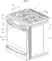
- FIG. 1 is a perspective view illustrating a cooking appliance according to an embodiment of the present disclosure
- FIG. 2 is a front view of the cooking appliance illustrated in FIG. 1
- FIG. 3 is a side cross-sectional view illustrating an internal configuration of the cooking appliance illustrated in FIG. 1 .
- the cooking appliance may include a cooktop part 20 and an oven part 30.
- An outer shape of a cooking appliance 1 may be formed by a body 10.
- the body 10 may be provided in a form including a substantially rectangular parallelepiped shape and may be formed of a material having a predetermined strength to protect a plurality of parts installed in an inner space thereof.
- the body 10 may include a cavity 11 forming a frame of the body 10 and a front panel 13 disposed in the front of the cavity 11 and forming a front surface of the body 10.
- a cooking chamber 31 may be formed inside the cavity 11, and an opening which makes the front of the cooking chamber 31 open may be formed inside the front panel 13.
- the cooktop part 20 may be disposed above the body 10.
- the cooktop part 20 may be provided to cook food by heating an open space, that is, food placed on the upper side thereof or a container in which food is contained.
- the cooktop part 20 may be provided with a top plate 21 that closes an upper end of the body 10 while forming an exterior of an upper surface of the cooktop part 20.
- At least one cooktop heating part 22 for heating to-be-cooked food or the container in which food is contained may be disposed in the cooktop part 20.
- the cooktop heating part 22 may be provided as a heating device using a gas fuel.
- the cooktop heating part 22 may be provided as a heater or induction heating part using electricity. In this way, a structure of the cooktop heating part 22 may be changed according to the type of a heat source being used.
- the oven part 30 may be disposed below the cooktop part 20.
- the cooking chamber 31 providing a space in which food is cooked may be provided in an inner space of the oven part 30.
- the cavity 11 may be formed in the form of a hexahedron having an open front surface, and the cooking chamber 31 may be formed inside the cavity 11. That is, the cooking chamber 31 may be formed with a space disposed inside the cavity 11 and having a substantially hexahedral shape and may be formed as a front open space.
- the cooking appliance may be provided with a heating part that heats the cooking chamber 31.
- the heating part may be provided as a heating device using a gas fuel.
- the heating part may be also provided as a heater using electricity. In this way, a structure of the heating part may be changed according to the type of a heat source being used.
- the heating part is provided as a heating device using a gas fuel. Accordingly, a broil burner 35 that heats an inner space of the cooking chamber 31 from the upper side may be provided above the cooking chamber 31, and a baker burner-type burner that heats the inner space of the cooking chamber 31 from the lower side may be further provided below the cooking chamber 31.
- a convection part 37 that heats the inner space of the cooking chamber 31 by convection of hot air may be further provided behind the cooking chamber 31.
- the convection part 37 allows air in the inner space of the cooking chamber 31 to forcibly flow. That is, the convection part 37 suctions and heats the air in the inner space of the cooking chamber 31, then allows the air to flow while the air is discharged to the inner space of the cooking chamber 31, and thus heats the inner space of the cooking chamber 31, thereby uniformly heating food located in the inner space of the cooking chamber 31.
- a door 32 that selectively opens or closes the cooking chamber 31 may be rotatably provided in the oven part 30.
- the door 32 may be provided to open or close the cooking chamber 31 in a pull-down manner in which an upper end thereof vertically rotates about a lower end thereof.
- the door 32 may be formed in an overall hexahedral shape having a predetermined thickness.
- a handle 33 may be disposed in the front of the door 32. The handle 33 is provided to be gripped when a user wants to rotate the door 32. The user may easily rotate the door 32 using the handle 33.
- a control panel 50 may be provided on an upper front portion of the cooking appliance, that is, an upper front surface of the cavity 11.
- the control panel 50 may form a part of a front outer shape of the cooking appliance.
- the control panel 50 may be provided with a knob 51 for adjusting an operation of the cooking appliance, a display 52 that displays an operation state of the cooking appliance, and the like.
- control panel 50 may be provided in a form in which an input unit 51 and the display 52 are installed in a control panel cover 50a disposed above the door 32 and in the front of the cooktop part 20.
- the input unit 52 may be provided with a plurality of operation switches through which the user may directly input an operation signal.
- the operation switch may be provided in the form of a knob capable of a rotation operation or may be provided in the form of a button or panel capable of a pushing operation or a touch operation.
- control panel 50 may be further provided with the display 52 that provides operation information on the cooking appliance, cooking information on food, or the like. The user may identify various pieces of information on the cooking appliance through the display 52.
- the display 52 may be provided in the form of a touch panel capable of a touch operation, and accordingly, the input unit 51 and the display 52 may both be configured on one touch panel.
- a rear space 34 may be provided behind the cooking chamber 31.
- the rear space 34 is disposed behind the cavity 11 and is a space partitioned from the cooking chamber 31 by a partition surface 30a that partitions the cooking chamber 31 and the rear space 34 in the front-rear direction.
- a front boundary surface of the rear space 34 may be defined by the partition surface 30a, and a rear boundary surface of the rear space 34 may be defined by a rear cover 15 installed behind the cavity 11.
- An upper space 40 may be provided outside the cavity 11.
- the upper space 40 may be disposed above the cavity 11 and behind the control panel 50.
- a space in which parts or electrical components constituting the cooktop heating part 22 are to be installed may be formed inside the upper space 40.
- a front surface of the upper space 40 may be shielded by the front panel 13.
- the front panel 13 may be disposed between the cavity 11 and the door 32. At least a portion of the front panel 13 may be disposed to block the front side of the upper space 40. For example, an upper region of the front panel 13 disposed above the cooking chamber 31 may shield the front surface of the upper space 40.
- the front panel 13 may be provided with an intake port 14.
- the intake port 14 may be formed to pass through the front panel 13 in the front-rear direction.
- the intake port 14 may form, on the front panel 13, a passage through which air outside the upper space 40 is to flow into the upper space 40.
- the cooktop part 20 is disposed above the oven part 30 and may include the top plate 21 and the cooktop heating part 22.
- the top plate 21 may be disposed above the cavity 11, and the upper space 40 may be disposed between the top plate 21 and the cavity 11. That is, the top plate 21 may cover an upper portion of the cavity 11 so that the upper space 40 is formed between the top plate 21 and the cavity 11.
- the upper space 40 may be provided outside the cavity 11.
- the upper space 40 may be disposed between the cavity 11 and the top plate 21 and behind the control panel 50.
- the space in which parts or electrical components constituting the cooktop heating part 22 are to be installed may be formed inside the upper space 40.
- the cooktop heating part 22 when the cooktop heating part 22 is provided as a heating device using a gas fuel, a burner for burning gas, a supply pipe for supplying the gas to the burner, a valve for adjusting supply of the gas to the burner, and the like may be arranged in the upper space 40.
- the cooktop heating part 22 when the cooktop heating part 22 is provided as a heating device using electricity, the heater, the induction heating part, and various electrical components for driving the heater and the induction heating part may be arranged in the upper space 40.
- the body 10 may further include side panels 17.
- the side panels 17 may be arranged on both sides of the cavity 11.
- the side panels 17 may cover lateral sides of the cavity 11 from the outside of the cavity 11 and form a lateral exterior of the body 10.
- the side panels 17 may cover the lateral sides of the cavity 11 and may be formed to extend upward from the cavity 11. Accordingly, a lateral boundary surface of the upper space 40 may be defined by the pair of side panels 17 extending upward from both sides of the cavity 11.
- the rear cover 15 may be disposed behind the cavity 11.
- the rear cover 15 may cover the rear side of the cavity 11 and form a rear exterior of the body 10.
- the rear cover 15 may define a rear boundary surface of the rear space 34 provided behind the cavity 11.
- the rear cover 15 may be provided with a vent hole 16.
- the vent hole 16 may be formed to pass through the rear cover 15 in the front-rear direction, and an air inflow/outflow passage for cooling electrical components arranged inside the rear space 34 may be formed on the rear cover 15.
- the rear cover 15 may cover the rear side of the cavity 11 and form to extend upward from the cavity 11. Accordingly, a rear boundary surface of the upper space 40 may be defined by the rear cover 15 extending upward from the rear side of the cavity 11.
- the front side, the rear side, and both lateral sides of the upper space 40 are surrounded by the front panel 13, the rear cover 15, and the pair of side panels 17, and the top plate 21 covers an upper portion of the upper space 40.
- the top plate 21 may be disposed above the front panel 13, the rear cover 15, and the pair of side panels 17 and may be coupled to each of the front panel 13, the rear cover 15, and the pair of side panels 17. That is, the top plate 21 may be fixed to the upper portion of the upper space 40 while being coupled to each of the front panel 13, the rear cover 15, and the pair of side panels 17.
- An exhaust duct 41 may be provided to discharge, to the outside of the cooking appliance, combustion gas generated while food is cooked inside the cooking chamber 31.
- the exhaust duct 41 may be provided so that a lower end thereof is connected to an upper portion of the cooking chamber 31 and an upper end thereof is disposed on an upper rear side of the cooking appliance 1.
- the upper end of the exhaust duct 41 may be disposed behind the cooktop part 20.
- the upper end of the exhaust duct 41 passes through the top plate 21 and is open to an upper portion of the cooktop part 20.
- the combustion gas generated in the cooking chamber 31 may flow into the exhaust duct 41 connected to the upper portion of the cooking chamber 31, may flow upward, and may be discharged upward from the rear surface of the cooking appliance 1 through the upper end of the exhaust duct 41.
- a vent grill 60 may be disposed above the exhaust duct 41.
- the vent grill 60 is provided to cover the upper end of the exhaust duct 41 from an upper portion of the top plate 21.
- the vent grill 60 may be provided to cover, from the top, a rear partial area of the top plate 21 including an area in which the upper end of the exhaust duct 41 is disposed.
- the vent grill 60 may cover, from the top, a portion in which the rear space 34 that is a space between a rear surface of the cavity 11 and the rear cover 15 is open upward, that is, an upper end opening formed between the partition surface 30a and the rear cover 15. Accordingly, a space surrounded by the vent grill 60, the top plate 21, and the rear cover 15 may be formed inside the vent grill 60.
- the vent grill 60 has a hexahedral shape having an open lower portion. At least one vent hole 61 through which the combustion gas discharged through the exhaust duct 41 is to pass may be provided in the vent grill 60.
- the vent hole 61 may be formed to vertically pass through an upper surface of the vent grill 60.
- FIG. 4 is an exploded perspective view illustrating a state in which a cavity, a broil burner, and an exhaust duct illustrated in FIG. 3 are separated
- FIG. 5 is a perspective view illustrating a coupling state of the cavity, the broil burner, and the exhaust duct illustrated in FIG. 4
- FIG. 6 is a side cross-sectional view illustrating a coupling state of the cavity, the broil burner, and the exhaust duct illustrated in FIG. 5 .
- a broil burner 35 may be provided inside the cooking chamber 31.
- the broil burner 35 may heat the inside of the cooking chamber 31 from the upper portion of the cooking chamber 31.
- the broil burner 35 includes a burner body 351, a mixing tube 353, and an ignition device 357.
- the burner body 351 is provided above the cooking chamber 31.
- the burner body 351 may be coupled to an upper surface of the cooking chamber 31 and may be formed in the form of a linear pipe having a length extending in the front-rear direction (hereinafter, referred to as a "front-rear direction") of the body 10.
- a passage to which mixed gas is supplied may be formed inside the burner body 351 to extend in the front-rear direction. Further, a flame hole may be formed to pass through a side portion of the burner body 351, and the flame hole forms a passage through which a gas inside the burner body 351 is discharged to the outside of the burner body 351.
- a plurality of flame holes may be arranged on the side portion of the burner body 351 to be spaced apart from each other at predetermined intervals in a length direction of the burner body 351. Accordingly, a plurality of gas discharge passages may be provided in the burner body 351 in the length direction of the burner body 351.
- the burner body 351 may receive a gas mixed with air, that is, a mixed gas, through a mixing tube 353, which will be described below, and in this way, the mixed gas supplied to the passage inside the burner body 351 may be combusted, while being discharged to the outside of the burner body 351 through the flame hole, so as to generate a flame outside the burner body 351.
- a gas mixed with air that is, a mixed gas
- the mixing tube 353 may be formed in the form of a linear pipe having one side connected to the burner body 351.
- the burner body 351 is formed in the form of a linear pipe extending in the front-rear direction
- the mixing tube 353 is formed in the form of a linear pipe extending in a left-right direction (hereinafter, referred to as a "left-right direction) of the body 10
- the burner body 351 and the mixing tube 353 are connected to form an " " " shape.
- a mixing passage in which a gas and air are mixed is formed inside the mixing tube 353.
- the mixing passage provides a space which is formed inside the mixing tube 353 formed in the form of a hollow pipe and in which a gas and air introduced into the mixing tube 353 may be mixed while flowing in a direction from the inside of the mixing tube 353 toward the burner body 351.
- a reflector 355 may be installed in the broil burner 35.
- the reflector 355 may serve to reflect the flame and heat generated while the mixed gas is burned in the broil burner 35 in the downward direction, that is, toward food inside the cooking chamber 31.
- the reflector 355 may serve to cause the combustion gas generated while the mixed gas is burned in the broil burner 35 to flow in the upward direction of the reflector 355, that is, to a space between a ceiling surface of the cooking chamber 31 and an upper surface of the reflector 355.
- An exhaust port 12 may be formed to vertically pass through an upper surface of the cavity 11.
- the exhaust duct 41 may be connected to the inside of the cooking chamber 31 through this exhaust port 12.
- the exhaust duct 41 may be provided to discharge, to the outside of the cooking appliance 1, the combustion gas generated while food is cooked inside the cooking chamber 31.
- the exhaust duct 41 may be provided so that the lower end thereof is connected to an upper portion of the cooking chamber 31 and the upper end thereof is disposed on an upper rear side of the cooking appliance 1.
- the upper end of the exhaust duct 41 may be disposed behind the cooktop part 20.
- the exhaust duct 41 includes a first duct part 411 and a second duct part 415.
- the first duct part 411 and the second duct part 415 may be arranged to be vertically connected, the first duct part 411 may be disposed on the lower side thereof, and the second duct part 415 may be disposed on the upper side thereof.
- the first duct part 411 is disposed adjacent to the exhaust port 12.
- the first duct part 411 may be disposed on one side surface of the cavity 11, that is, the upper surface of the cavity 11, and the second duct part 415.
- a first exhaust passage 411a connected to the exhaust port 12 may be formed inside the first duct part 411.
- the first duct part 411 may include a plurality of sidewalls connecting the upper surface of the cavity 11 and the second duct part 415.
- the plurality of sidewalls may be connected to each other while surrounding the first exhaust passage 411a in the front-rear direction and the left-right direction.
- the first duct part 411 may be formed in a form in which four side walls are connected to form a quadrangular shape, in other words, in the form of a hexahedral shape including four sidewalls and having an open upper end and an open lower end.
- first duct part 411 may further include a coupling part 413.
- the coupling part 413 is provided to couple the exhaust duct 41 and the cavity 11.
- the coupling part 413 may protrude from a plurality of sidewalls to be coupled to one side surface of the cavity 11, that is, the upper surface of the cavity 11.
- the coupling part 413 may protrude from a lower end of any one of the plurality of sidewalls in a direction parallel to one side surface of the cavity 11.
- the coupling part 413 may protrude from the lower end of each of the sidewalls, and the coupling part 413 may protrude from the lower end of the sidewall and, along with the sidewall, may form an "L" shape.
- the second duct part 415 may be disposed between the first duct part 411 and the vent grill 60.
- a second exhaust passage 415a may be formed inside the second duct part 415.
- One side of the second exhaust passage 415a may be connected to the first exhaust passage 411a, and the other side of the second exhaust passage 415a may be open to the upper side of the exhaust port 12.
- a lower end of the second exhaust passage 415a may be connected to the first exhaust passage 411a, and an upper end of the second exhaust passage 415a may be open to the vent grill 60.
- the first exhaust passage 411a and the second exhaust passage 415a are connected vertically, and the first exhaust passage 411a and the second exhaust passage 415a connected in this way may be collectively called exhaust passages 411a and 415a.
- the second duct part 415 may be disposed behind the exhaust port 12. That is, the second duct part 415 may be disposed behind a lower end of the first duct part 411.
- the first duct part 411 connecting the second duct part 415 and the exhaust port 12 may extend from the exhaust port 12 toward the second duct part 415 in an upwardly inclined direction. That is, the first duct part 411 may be installed to be inclined in the rearward direction as the first duct part 411 goes to the upper side.
- a rear sidewall 412 that is a sidewall located at the rearmost location among the plurality of sidewalls forming the first duct part 411 may be a sidewall located at the lowest location among the plurality of sidewalls.
- the combustion gas flowing into a space between the ceiling surface of the cooking chamber 31 and the upper surface of the reflector 355 may be discharged to the outside of the cooking chamber 31 through the exhaust port 12 formed in the upper surface of the cavity 11.
- combustion gas discharged through the exhaust port 12 may flow upward through the exhaust passages 411a and 415b formed inside the exhaust duct 41 and may be discharged upward while passing through the vent grill 60 from the rear side of the cooking appliance 1.
- the broil burner 35 may be provided with the ignition device 357.
- the ignition device 357 serves to ignite the mixed gas discharged from the flame hole.
- the ignition device 357 may include a heating element having a ceramic-coated surface. The temperature of the mixed gas discharged from the flame hole of the broil burner 35 may be increased to an ignition temperature due to heat generated by the heating element of the ignition device 357, and accordingly, the broil burner 35 may be ignited.
- the ignition device 357 may be disposed between the ceiling surface of the cooking chamber 31 and the reflector 355. In more detail, the ignition device 357 may be disposed below the exhaust port 12. That is, the ignition device 357 may be disposed between the exhaust part 12 and the reflector 355.
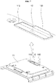
- FIG. 7 is a perspective view illustrating a state in which an upper surface of the cavity and a blocking part illustrated in FIG. 5 are separated
- FIG. 8 is a cross-sectional view taken along line "VIII-VIII” of FIG. 5
- FIG. 9 is a cross-sectional view taken along line "IX-IX” of FIG. 5 .
- a blocking part 100 may be provided inside the exhaust duct 41.
- the blocking part 100 is provided to block at least a portion of a movement path of water flowing downward from the exhaust passages 411a and 415a inside the exhaust duct 41 toward the exhaust port 12.
- the blocking part 100 may be disposed between the other side of the exhaust passages 411a and 415a and the exhaust port 12, that is, between an open upper end of the exhaust passages 411a and 415a and the exhaust port 12.
- the blocking part 100 is disposed inside the first duct part 411.
- the blocking part 100 may be disposed between the exhaust port 12 and the rear sidewall 412 that is a sidewall disposed on the rearmost side among the plurality of sidewalls forming the first duct part 411. That is, the blocking part 100 may be disposed between the exhaust port 12 and the rear sidewall 412 inside the first duct part 411.
- the blocking part 100 may be provided to protrude vertically from the one side surface of the cavity 11.
- the blocking part 100 is provided on the upper surface of the cavity 11 and is formed to protrude vertically.
- the exhaust port 12 and the rear sidewall 412 may be connected to each other by the one side surface of the cavity 11, that is, the upper surface of the cavity 11. Further, the blocking part 100 may be formed to protrude upward from the upper surface of the cavity 11. That is, the blocking part 100 may be formed integrally with the cavity 11, and the blocking part 100 may be formed by a portion of the upper surface of the cavity 11.
- the portion of the upper surface of the cavity 11 may be vertically perforated to form the exhaust port 12.
- the blocking part 100 may be formed in a form in which a portion of an edge of the cavity 11 surrounding the exhaust port 12 extends upward.
- a protrusion wall part 110 may be provided in the edge of the cavity 11 surrounding the exhaust port 12.
- the protrusion wall part 110 may be formed to protrude upward from the edge of the cavity 11 surrounding the exhaust port 12.
- the protrusion wall part 110 may be formed in the form of a wall surface externally surrounding the exhaust port 12 in a radial direction and may be formed in the form of a wall surface protruding upward from the exhaust port 12 and the edge of the cavity 11 surrounding the exhaust port 12.
- the protrusion wall part 110 may be formed in the form of a burr that is generated when the upper surface of the cavity 11 is perforated from the bottom to the top to form the exhaust port 12.
- a periphery of the exhaust port 12 may be surrounded by the protrusion wall part 110 surrounding a radially outer side of the exhaust port 12.
- the blocking part 100 may be formed in a form in which a portion of the edge of the cavity 11 surrounding the exhaust port 12 protrudes or extends upward.
- the protrusion wall part 110 is formed to completely surround the periphery of the exhaust port 12, unlike the protrusion wall part 110, the blocking part 100 does not completely surround the periphery of the exhaust port 12 but may be disposed only in the portion of the edge of the cavity 11 surrounding the exhaust port 12.
- the height of the blocking part 100 is greater than the height of the protrusion wall part 110. That is, the blocking part 100 may be formed to protrude upward further than the protrusion wall part 110.
- the blocking part 100 may be disposed between the other side of the exhaust passages 411a and 415a and the ignition device 357.
- the blocking part 100 is disposed between the second exhaust passage 415a and the exhaust port 12.
- the ignition device 357 may be exposed to the upper portion of the exhaust port 12, and the blocking part 100 may be disposed between the exhaust port 12 and the second exhaust passage 415a to block at least a portion of a passage between the second exhaust passage 415a and the exhaust port 12.
- the blocking part 100 may block a movement path of water flowing downward from the exhaust passages 411a and 415a toward the ignition device 357.
- the blocking part 100 may be disposed behind the ignition device 357.
- the blocking part 100 may be disposed behind the exhaust port 12 and thus may be disposed behind at least a portion of the ignition device 357 exposed to the upper portion of the cavity 11, that is, toward the exhaust passages 411a and 415a, through the exhaust port 12. That is, the blocking part 100 may be disposed behind a portion of the ignition device 357 that is exposed to the upper portion of the cavity 11 through the exhaust port 12.
- the width of the blocking part 100 in the left-right direction may be set to be smaller than or equal to the width of the exhaust port 12 in the left-right direction.
- the width of the blocking part 100 in the left-right direction may be set to a value between the width of the ignition device 357 in the left-right direction and the width of the exhaust port 12 in the left-right direction.
- the width of the blocking part 100 in the left-right direction may be set to be greater than the width of the ignition device 357 in the left-right direction and to be smaller than the width of the exhaust port 12 in the left-right direction.
- the blocking part 100 may be formed to protrude further than the ignition device 357 in the left-right direction. That is, when viewed from the top, both ends of the blocking part 100 in the left-right direction may be formed to protrude to the left side and the right side further than the ignition device 357.
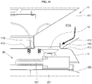
- FIG. 10 is a view illustrating a water flow state inside an exhaust duct illustrated in FIG. 8
- FIG. 11 is a view illustrating a water flow state inside an exhaust duct illustrated in FIG. 9 .
- the blocking part 100 may be disposed behind the exhaust port 12, disposed behind the ignition device 357, formed to protrude further than the ignition device 357 in the left-right direction, and formed to protrude upward further than the protrusion wall part 110 surrounding the exhaust port 12.
- the water may flow into the exhaust duct 41 through the exhaust port 12 of the vent grill 60. Further, in this way, the water flowing into the exhaust duct 41 may flow downward toward the exhaust port 12 through the exhaust passages 411a and 415a.
- the water introduced into the exhaust duct 41 flows downward toward the exhaust port 12 mainly along the rear sidewall 412 inside the exhaust passages 411a and 415a. In this way, at least a portion of the flow of the downward flowing water is blocked by the blocking part 100 disposed between the second exhaust passage 415a and the exhaust port 12.
- the blocking part 100 is disposed behind the exhaust port 12 and provided to block a gap between the exhaust passages 411a and 415a and the ignition device 357.
- the blocking part 100 may block the flow of the water flowing downward toward the ignition device 357 inside the exhaust passages 411a and 415a main along the rear sidewall 412.
- the water flowing downward along the exhaust duct 41 is blocked by the blocking part 100, does not flow downward toward a lower portion of the exhaust port 12, and is spread to the periphery of the exhaust port 12.
- the periphery of the exhaust port 12 is surrounded by the protrusion wall part 110. That is, the periphery of the exhaust port 12 is surrounded by the blocking part 100 and the protrusion wall part 110, and a passage connecting the exhaust passages 411a and 415a and the exhaust port 12 is in a state of being blocked by the blocking part 100 and the protrusion wall part 110.
- the water blocked by the blocking part 100 and spread to the periphery of the exhaust port 12 may not flow downward toward the ignition device 357 through the exhaust port 12 eventually and may be removed by being vaporized by the heat of the cavity 11 heated by operating the heating part such as the broil burner 35 while being spread from the upper surface of the cavity 11.
- the blocking part 100 is formed to protrude upward further than the protrusion wall part 110. Unlike the protrusion wall part 110 surrounding the periphery of the exhaust port 12, the blocking part 100 is formed to have a width sufficient to block movement of the water to the ignition device 357 without surrounding the entire periphery of the exhaust port 12. That is, the blocking part 100 is formed so as not to surround the entire periphery of the exhaust port 12.
- the blocking part 100 is a structure protruding from the inside of the exhaust passages 411a and 415a, and in this way, the structure protruding from the inside of the exhaust passages 411a and 415a may act as obstacles that hinder exhaust flow inside the exhaust passages 411a and 415a.
- the width of the blocking part 100 becomes greater, and as the height of the blocking part 100 becomes greater, penetration of the water into the ignition device 357 may be blocked more effectively.
- the width of the blocking part 100 becomes greater, and as the height of the blocking part 100 becomes greater, obstruction the exhaust flow made by the blocking part 100 inside the exhaust passages 411a and 415a inevitably becomes severe.
- the width and the height of the blocking part 100 are set to a length at which the penetration of the water into the ignition device 357 may be effectively blocked even without hindering the exhaust flow inside the exhaust passages 411a and 415a.
- the width of the blocking part 100 may be formed to be slightly greater than the width of the ignition device 357.
- the blocking part 100 may be formed in a width at which both sides of the blocking part 100 in the left-right direction may protrude from both sides of the ignition device 357 in the left-right direction by the range of about 10 mm to 20 mm.
- the width of the blocking part 100 may be set in the range of about 65 mm to 85 mm.
- the height of the blocking part 100 may be set to be greater than the height of the protrusion wall part 110 and may be set to a height at which a sufficient space required for the flow of the combustion gas is secured between an upper end of the blocking part 100 and a ceiling surface of the exhaust duct 41.
- the height of the blocking part 100 may be set in consideration of whether the penetration of the water into the ignition device 357 may be blocked and the concentration of carbon monoxide (CO) in the combustion gas discharged through the exhaust duct 41.
- the height of the blocking part 100 may be set to a height at which, when the set amount of the water flows into the exhaust duct 41, the penetration of the water into the ignition device 357 may be blocked effectively, and the concentration of carbon monoxide (CO) in the combustion gas discharged through the exhaust duct 41 may be maintained at a set value or less.
- CO carbon monoxide
- the blocking part 100 is formed to protrude vertically upward.
- the blocking part 100 When the blocking part 100 is formed to be inclined forward toward the exhaust port 12, a possibility that the water flowing downward from the inside of the exhaust duct 41 may not be blocked by the blocking part 100 and may overflow toward the exhaust port 12 over the blocking part 100 increases.
- the blocking part 100 when the blocking part 100 is formed to be inclined forward toward the exhaust port 12, the blocking part 100 may become an obstacle that narrows a gap between the upper end of the blocking part 100 and the ceiling surface of the exhaust duct 41 to obstruct the exhaust flow.
- the blocking part 100 when the blocking part 100 is formed to be inclined forward toward the exhaust port 12, in order to prevent the water from overflowing, the length of the blocking part 100 should be further increased. In this case, the blocking part 100 inevitably becomes an obstacle that more seriously obstructs the exhaust flow.
- the blocking part 100 when the blocking part 100 is formed to be inclined rearward toward the rear sidewall 412, a possibility that the blocking part 100 hinders the exhaust flow can be significantly reduced. However, in this case, since the gap between the blocking part 100 and the exhaust duct 41 is narrowed, a possibility that the water cannot be properly blocked by the blocking part 100 increases.
- the blocking part 100 is formed to protrude vertically upward. In this way, since the blocking part 100 is formed to be protrude vertically upward, the penetration of the water into the ignition device 357 may be effectively blocked, and despite the existence of the protrusion structure such as the blocking part 100, the exhaust flow inside the exhaust duct 41 may be smoothly maintained.
- the protrusion wall part 110 surrounding the exhaust port 12 at a location adjacent to the blocking part 100, along with the blocking part 100, may serve to block the penetration of the water into the ignition device 357.
- the water spread out from the upper surface of the cavity 11 may not flow downward to the lower portion of the exhaust port 12 due to the protrusion wall part 110 surrounding the exhaust port 12 and protruding upward and may be vaporized by the heat of the cavity 11 while staying on the upper surface of the cavity 11. That is, the protrusion wall part 110 may serve to assist a function of the blocking part 100 in the vicinity of the blocking part 100.
- the protrusion wall part 110 may be formed in a form in which the portion of the edge of the cavity 11 surrounding the exhaust port 12 protrudes or extends upward. Accordingly, a wall surface by the protrusion wall part 110 instead of a sharp cut surface may be formed in an inner edge of the cavity 11 surrounding the exhaust port 12. As a result, the risk that a worker is injured due to the sharp cut surface around the exhaust port 12 can be significantly reduced.
- the protrusion structure such as the protrusion wall part 110 is formed on the upper surface of the cavity 11
- the upper surface of the cavity 11 may be flattened more easily, and accordingly, the flattening of the upper surface of the cavity 11 may be performed more effectively.
- the protrusion wall part 110 forming the protrusion structure on the upper surface of the cavity 11 may serve to guide an installation location of the exhaust duct 41.
- an installation location of the exhaust duct 41 with respect to the cavity 11 may be guided to a location in which interference occurs between an inner surface of the first duct part 411 and the protrusion wall part 110. Accordingly, the exhaust duct 41 may be installed more easily, more rapidly, and more accurately.
- a flow path of the water to the ignition device 357 through the exhaust port 12 from the exhaust passages 411a and 415a is blocked using the blocking part 100 protruding upward from the upper surface of the cavity 11 and disposed inside the exhaust duct 41 and behind the exhaust port 12, and thus the water introduced through the exhaust duct 41 from the outside of the cooking appliance 1 may be effectively blocked from penetrating into the heat source.
- the flow path of the water to the ignition device 357 through the exhaust port 12 from the exhaust passages 411a and 415a is blocked by the blocking part 100, the water introduced through the exhaust duct 41 from the outside of the cooking appliance 1 may be effectively blocked from being introduced into the ignition device 357, and accordingly, occurrence of an ignition failure of the broil burner 35 may be effectively suppressed.
- the cooking appliance having the blocking part as configured above is merely an exemplary embodiment of the present disclosure, and various embodiments that may replace the embodiment may be present.
- FIG. 12 is a view illustrating a configuration of a blocking part according to another embodiment of the present disclosure.
- a blocking part 200 may be formed in an exhaust duct 241 instead of the cavity 11.
- At least one of coupling parts 414 of the exhaust duct 241 may include a first protrusion part 414a and a second protrusion part 414b.
- the coupling part 414 located at a lower end of a rear sidewall 412 includes the first protrusion part 414a and the second protrusion part 414b.
- the first protrusion part 414a may extend rearward from the rear sidewall 412 to protrude rearward from the rear sidewall 412.
- the first protrusion part 414a may form a flat surface parallel to the upper surface of the cavity 11 and may protrude rearward from the rear sidewall 412.
- the second protrusion part 414b is formed to extend from a lower end of the first protrusion part 414a.
- the second protrusion part 414b may be formed to extend from the lower end of the first protrusion part 414a to the front side of the rear sidewall 412.
- the second protrusion part 414b may be formed in a flat surface parallel to the first protrusion part 414a and a connection portion between the rear sidewall 412 and the first protrusion part 414a may be provided at a rear end of the rear sidewall 412.
- connection portion between the first protrusion part 414a and the second protrusion part 414b may be provided at a front end of the rear sidewall 412, and the second protrusion part 414b may be disposed below the first protrusion part 414a and disposed between the upper surface of the cavity 11 and the first protrusion part 414a.
- the second protrusion part 414b may be coupled to the cavity 11 while being in contact with the upper surface of the cavity 11.
- the blocking part200 may extend upward from a front end of the second protrusion part 414b.
- the blocking part 200 may be formed to protrude upward from one side surface of the cavity 11, that is, the upper surface of the cavity 11.
- the blocking part 200 may be disposed inside the exhaust duct 241 and disposed between the rear sidewall 412 and the exhaust port 12.
- the blocking part 200 may be formed integrally with the exhaust duct 241. That is, the blocking part 200 of the present embodiment may be formed integrally with the exhaust duct 241 by bending a lower end of the exhaust duct 241.
- the blocking part 200 Like the blocking part 100 as described in the above embodiment, in the blocking part 200, the water introduced through the exhaust duct 241 from the outside of the cooking appliance 1 can be effectively blocked from penetrating into the heat source. Therefore, occurrence of an ignition failure of the broil burner 35 can be effectively suppressed, and of course, the blocking part 200 may be easily processed on the exhaust duct 241 only using a simple operation of simply changing the shape of the exhaust duct 241.
- the blocking part 200 of the present embodiment can be easily manufactured only using a simple operation of adding a bending process to the exhaust duct 241 and can be easily applied to the cooking appliance 1 only using a simple operation of installing the exhaust duct 241, in which the blocking part is processed, in the cooking appliance 1.
- a water flow path through which water flows from an exhaust passage through an exhaust port to an ignition device 357 is blocked using a blocking part that protrudes upward from an upper surface of a cavity and is disposed inside an exhaust duct and behind the exhaust port, and thus the penetration of the water introduced through the exhaust duct from the outside of the cooking appliance can be effectively blocked.
- the water flow path through which water flows from the exhaust passage through the exhaust port to the ignition device is blocked using the blocking part, the water introduced through the exhaust duct from the outside of the cooking appliance can be effectively blocked from being introduced into the ignition device, and thus the occurrence of an ignition failure of a heat source such as a boil burner can be effectively suppressed.
Landscapes
- Engineering & Computer Science (AREA)
- Chemical & Material Sciences (AREA)
- Combustion & Propulsion (AREA)
- Mechanical Engineering (AREA)
- General Engineering & Computer Science (AREA)
- Baking, Grill, Roasting (AREA)
- Control And Other Processes For Unpacking Of Materials (AREA)
- General Preparation And Processing Of Foods (AREA)
- Cookers (AREA)
Abstract
Description
- The present disclosure relates a cooking appliance, and more particularly, to a cooking appliance including both of a cooktop part and an oven part.
- Cooking appliances are one kind of home appliances for cooking food and are installed in a kitchen space to cook food according to an intention of a user. These cooking appliances may be classified into various types according to a heat source or type being used and the type of fuel.
- The cooking appliances are classified according to the type of cooking, the cooking appliances may be classified into open-type cooking appliances and closed-type cooking appliances according to the shape of a space in which food is placed. Closed-type cooking appliances include ovens, microwave ovens, and the like, and open-type cooking appliances include cooktops, hops, griddles, and the like.
- A closed-type cooking appliance is a cooking appliance provided with a space in which food is located and which is shielded to cook the food by heating the shielded space. The closed-type cooking appliance is provided with a cooking chamber provided with a space which is shielded when food is cooked while the food is placed therein. The cooking chamber provides a space in which the food is substantially cooked.
- Closed-type cooking appliances are roughly classified into gas ovens and electric ovens according to the type of a heat source. In a gas oven, a gas is used as a fuel, and as the gas is supplied to a plurality of burners and the burners are ignited, food is cooked by a flame generated while the supplied gas is burned. Unlike the gas oven, in an electric oven, electricity is used as a heat source, and food is cooked by heat emitted from heaters while the plurality of heaters are operated.
- A door that selectively opens or closes the cooking chamber may be rotatably provided in the closed-type cooking appliance. The door is rotatably installed in a body, in which the cooking chamber is formed, using a door hinge provided between the body and the door, and as the door is rotated about a portion coupled to the body through the door hinge, the cooking chamber may be selectively opened or closed.
- The heat source is provided in an inner space of the cooking chamber opened or closed by the door and heats the cooking chamber. A gas burner, an electric heater, or the like may be used as the heat source.
- In addition, the closed-type cooking appliance is provided with an exhaust duct. The exhaust duct is provided to discharge, to the outside of the cooking appliance, combustion gas generated while the food is cooked inside the cooking chamber.
- The exhaust duct is provided so that a lower end thereof is connected to an upper portion of the cooking chamber and an upper end thereof is disposed on the rear upper side of the cooking appliance. The combustion gas generated in the cooking chamber flows into the exhaust duct connected to the upper portion part of the cooking chamber, flows upward, and is discharged upward from the rear surface of the cooking appliance through a vent grill provided above the exhaust duct.
- At least one exhaust hole through which the combustion gas discharged through the exhaust duct is to pass is provided in the vent grill, and the exhaust hole is formed to vertically pass through the vent grill.
- In recent years, complex cooking appliances have been proposed in which the closed-type cooking appliance and the open-type cooking appliance are installed at the same time, a plurality of heat sources are combined, and thus various types of food may be cooked and a plurality of pieces of food may be cooked simultaneously. The cooking appliance in which the plurality of heat sources are installed is accompanied by a flow path of cooling air for cooling the plurality of heat sources and electronic components.
- In the complex cooking appliance, the open-type cooking appliance is located on the closed-type cooking appliance. Further, in the open-type cooking appliance, the plurality of heaters or the plurality of burners are installed so that a plurality of dishes may be cooked simultaneously.
- That is, when a user cooks an oven dish such as a barbecue dish or bread or a roast dish such as a grilled fish, the cooking is performed using the closed-type cooking appliance, and when the user cooks a general dish in which food is heated while being placed in a container, the cooking is performed using the open-type cooking appliance of which an upper portion is open.
- One of the most commonly used open-type cooking appliances is a gas stove-type open cooking appliance, which cooks food using a flame generated when gas is burned by the burner.
- The burner provided in this open-type cooking appliance generally includes a burner body, a burner head, and a burner head cap.
- Accordingly, the burner body having a flow path through which a gas is supplied is fixedly installed inside a cooktop case forming an outer shape of the open-type cooking appliance, the burner head through which the gas supplied through the flow path is discharged is installed above the burner body, and the burner head cap is installed above the burner head.
- A gas supply pipe for supplying a gas and a nozzle for injecting the gas may be mounted on the burner body. Further, the burner head may be located on a member defining an upper surface of the open-type cooking appliance, for example, an upper surface of a top plate, and the burner head cap is seated on the upper side of the burner head.
- In the complex cooking appliance, the vent grill is generally disposed on the upper side of a rear surface of the open-type cooking appliance. For example, an upper end of the exhaust duct may pass through the top plate and may be disposed on the rear surface side of the open-type cooking appliance, and the vent grill may be disposed on the upper side thereof, that is, an upper side of the rear surface of the top plate.
- Meanwhile, a lower end of the exhaust duct may be connected to an upper surface of a cavity. An exhaust port may be formed to vertically pass through the upper surface of the cavity, and the exhaust duct may be connected to the interior of the cooking chamber through the exhaust port.
- The heat source is provided in the inner space of the cooking chamber to heat the cooking chamber, and the gas burner, the electric heater, or the like may be used as the heat source. Among them, as in a broil burner or a broil heater, the heat source disposed above the cooking chamber is disposed adjacent to the exhaust port, and at least a part of the heat source is disposed below the exhaust port.
- According to the above structure, water may flow into the exhaust duct through the exhaust hole of the vent grill. Further, the water introduced into the exhaust duct in this way may penetrate toward the heat source disposed below the exhaust duct.
- In this way, the water penetrating toward the heat source may affect a normal ignition or operation of the heat source. For example, when the water penetrates into an electric connection part of the broil heater, the risk of an accident increases, and when the water penetrates into an ignitor of the broil burner, the risk of an ignition failure of the broil burner increases.
- The present disclosure is directed to providing a cooking appliance having an improved structure capable of blocking water, which is introduced through an exhaust duct from the outside of the cooking appliance, from penetrating into a heat source.
- The present disclosure is also directed to providing a cooking appliance having an improved structure capable of suppressing the occurrence of an ignition failure of a broil burner.
- A cooking appliance according to an embodiment of the present disclosure includes an exhaust passage that is formed inside an exhaust duct and has one side connected to the inside of a cooking chamber through an exhaust port and the other side that is open to an upper portion of a top plate, and a blocking part that is provided inside the exhaust duct having the exhaust passage and blocks at least a portion of a movement path of water flowing downward toward the exhaust port from the exhaust passage.
- In this way, a water flow path through which water flows from the exhaust passage through the exhaust port to an ignition device is blocked using the provided blocking part, and thus penetration of the water introduced through the exhaust duct from the outside of the cooking appliance may be effectively blocked.
- Further, according to another aspect of the present disclosure, a blocking part is disposed between an upper end of an exhaust passage and an ignition device, and the blocking part blocks a movement path of water flowing downward from the exhaust passage to the ignition device.
- Thus, a water flow path through which water flows from the exhaust passage through an exhaust port to the ignition device may be blocked by the blocking part, and as a result, occurrence of an ignition failure of a broil burner may be effectively suppressed.
- A cooking appliance according to an aspect of the present disclosure includes an oven part including a cavity in which a cooking chamber is formed, a cooktop part that includes a top plate covering an upper portion of the cavity so that an upper space is formed between the cavity and the top plate and at least one cooktop heating part of which at least a portion is disposed in the upper space, and an exhaust duct that forms a passage connecting an inside of the cooking chamber and an upper portion of the top plate, wherein the oven part includes an exhaust port vertically passing through one side surface of the cavity that faces the cooktop part, an exhaust passage having one side connected to the exhaust port and the other side that is open to the upper portion of the top plate is formed inside the exhaust duct, and the blocking part that blocks at least a portion of a movement path of water flowing downward toward the exhaust port from the exhaust passage is provided inside the exhaust duct.
- The blocking part may be disposed between the other side of the exhaust passage and the exhaust port and may be provided to protrude vertically from the one side surface of the cavity.
- The blocking part may be provided on the one side surface of the cavity and may protrude vertically.
- The blocking part may be formed integrally with the cavity.
- A portion of the one side surface of the cavity may be vertically perforated to form the exhaust port, and the blocking part may be formed in a form in which a portion of an edge of the cavity surrounding the exhaust port extends upward.
- The cooking appliance may further include a burner disposed inside the cooking chamber.
- The burner may include an ignition device disposed below the exhaust port.
- The blocking part may be disposed between the other side of the exhaust passage and the ignition device to block a movement path of water flowing downward toward the ignition device from the exhaust passage.
- The blocking part may be disposed behind the ignition device, a width of the blocking part in a left-right direction may be greater than a width of the ignition device in the left-right direction, and the blocking part may protrude further than the ignition device in the left-right direction.
- The exhaust duct may include a first duct part having a first exhaust passage formed therein and connected to the exhaust port and a second duct part having a second exhaust passage formed therein and having one side connected to the first exhaust passage and the other side that is open to the upper portion of the exhaust port.
- The second duct part may be disposed behind the exhaust port, the first duct part may extend to be inclined upward from the exhaust port toward the second duct part, and the blocking part may be disposed inside the first duct part.
- The first duct part may include a plurality of sidewalls connecting the one side surface of the cavity and the second duct part, the plurality of sidewalls may be connected to each other while surrounding the first exhaust passage in a front-rear direction and in the left-right direction, and the blocking part may be disposed between the exhaust port and a rear sidewall that is a rearmost sidewall among the plurality of sidewalls.
- The rear sidewall and the exhaust port may be connected to each other by the one side surface of the cavity, and the blocking part may protrude upward from the one side surface of the cavity.
- The first duct part may further include a coupling part protruding from the plurality of sidewalls and coupled to the one side surface of the cavity, and the coupling part may protrude from a lower end of at least one of the plurality of sidewalls in a direction parallel to the one side surface of the cavity.
- The coupling part may include a first protrusion part extending rearward from the rear sidewall and protruding rearward from the rear sidewall and a second protrusion part extending from a lower end of the first protrusion part and protruding forward from the rear sidewall.
- The blocking part may extend upward from a front end of the second protrusion part and protrude upward from an upper portion of the one side surface of the cavity.
- The portion of the one side surface of the cavity may be vertically perforated to form the exhaust port, and a protrusion wall part protruding upward from the edge of the cavity surrounding the exhaust port may be provided in the vicinity of the exhaust port.
- The blocking part may be formed in a form in which the portion of the edge of the cavity surrounding the exhaust port extends upward, and a height of the blocking part may be greater than a height of the protrusion wall part.
- The above and other objects, features and advantages of the present disclosure will become more apparent to those of ordinary skill in the art by describing exemplary embodiments thereof in detail with reference to the accompanying drawings, in which:
-
FIG. 1 is a perspective view illustrating a cooking appliance according to an embodiment of the present disclosure; -
FIG. 2 is a front view of the cooking appliance illustrated inFIG. 1 ; -
FIG. 3 is a side cross-sectional view illustrating an internal configuration of the cooking appliance illustrated inFIG. 1 ; -
FIG. 4 is an exploded perspective view illustrating a state in which a cavity, a broil burner, and an exhaust duct illustrated inFIG. 3 are separated; -
FIG. 5 is a perspective view illustrating a coupling state of the cavity, the broil burner, and the exhaust duct illustrated inFIG. 4 ; -
FIG. 6 is a side cross-sectional view illustrating a coupling state of the cavity, the broil burner, and the exhaust duct illustrated inFIG. 5 ; -
FIG. 7 is a perspective view illustrating a state in which an upper surface of the cavity and a blocking part illustrated inFIG. 5 are separated; -
FIG. 8 is a cross-sectional view taken along line "VIII-VIII" ofFIG. 5 ; -
FIG. 9 is a cross-sectional view taken along line "IX-IX" ofFIG. 5 ; -
FIG. 10 is a view illustrating a water flow state inside an exhaust duct illustrated inFIG. 8 ; -
FIG. 11 is a view illustrating a water flow state inside an exhaust duct illustrated inFIG. 9 ; and -
FIG. 12 is a view illustrating a configuration of a blocking part according to another embodiment of the present disclosure. - In the description of the present disclosure, when it is determined that a detailed description of widely known technologies related to the present disclosure may make the subject matter of the present disclosure unclear, the detailed description may be omitted. Hereinafter, embodiments of the present disclosure will be described in detail with reference to the accompanying drawings. In the drawings, the same reference numerals are used to indicate the same or similar components.
- Although first, second, and the like are used to describe various components, it is apparent that these components are not limited by these terms. These terms are only used to distinguish one component from another component, and it is apparent that a first component may be a second component unless particularly otherwise stated.
- The present disclosure is not limited to the following embodiments, but various changes may be made, and the present disclosure may be implemented in various different forms. The present embodiment is merely provided to complete the disclosure of the present disclosure and to fully inform those skilled in the art of the scope of the present disclosure. Thus, it should be understood that the present disclosure is not limited to the following embodiments and includes all changes, equivalents, or substitutes included in the scope of the present disclosure as well as substituting or adding a configuration of any one embodiment for or to a configuration of another embodiment.
- It should be understood that the accompanying drawings are merely provided to easily understand the embodiments disclosed in the present specification, and the accompanying drawings include all changes, equivalents, and substitutes included in the technical scope of the present disclosure. In the drawings, the sizes or thicknesses of components may be expressed exaggeratedly large or small in consideration of convenience of understanding or the like, but the protection scope of the present disclosure should not be interpreted as being limited thereto.
- Terms used in the present specification are used only to describe specific implementations and embodiments and are not intended to limit the present disclosure. Further, singular expressions include plural expressions unless clearly otherwise indicated in the context. In the specification, terms such as includes or consists of are intended to designate the presence of a feature, a number, a step, an operation, a component, a part, or combinations thereof described in the specification. That is, in the specification, it should be understood that the terms such as includes and consists of do not preclude the possibility of existence or addition of one or more features, numbers, steps, operations, components, parts, or combinations thereof.
- Terms including an ordinal number such as first and second may be used to describe various components, but the components are not limited by the terms. The terms are used only for the purpose of distinguishing one component from another component.
- It should be understood that, when it is referenced that a first component is "connected" or "coupled" to a second component, the first component may be directly connected or coupled to the second component or a third component may be present between the first component and the second component. On the other hand, it should be understood that, when a first component is "directly connected" or "directly coupled" to a second component, a third component is not present therebetween.
- It should be understood that when it is referenced that a first component is located "above" or "below" a second component, a third component may be present therebetween as well as the first component may be present directly above the second component.
- Unless otherwise defined, all terms used herein including technical or scientific terms have the same meanings as those commonly understood by those skilled in the art to which the present disclosure belongs. Terms defined in commonly used dictionaries should be interpreted as having the same meanings in the context of the related art and may not be interpreted with ideal or excessively formal meanings, unless explicitly defined in the present application.
- A direction in which a door is installed with respect to the center of a cooking appliance in a state in which the cooking appliance is placed on the floor is defined as a forward direction. Thus, a direction in which food enters the cooking appliance while the door is opened is defined as a rearward direction. For convenience, a direction toward the front side or the rear side may be referred to as a first direction. Then, the front side may be one side of the first direction, and the rear side may be the other side of the first direction.
- Further, a direction of gravity may be defined as a downward direction, and a direction opposite to the direction of gravity may be defined as an upward direction.
- Further, a horizontal direction perpendicular to the front-rear direction of the cooking appliance, that is, a width direction of the cooking appliance when the cooking appliance is viewed from the front side of the door of the cooking appliance may be referred as to a left-right direction. For convenience, the left-right direction may be defined as a second direction. Then, the right side may be one side of the second direction, and the left side may be the other side of the second direction.
- Further, the width direction of the cooking appliance may be defined as a lateral direction. Then, the right side may be one side of the lateral direction, and the left side may be the other side of the lateral direction.
- Further, the above-described up-down direction may be defined as a third direction. Then, the upper side may be one side of the third direction, and the lower side may be the other side of the third direction.
- Further, the above-described up-down direction may be defined as a vertical direction. Then, the front-rear direction and the left-right direction, that is, the first direction and the second direction, may be referred to as a horizontal direction.
- Throughout the specification, when "A and/or B" is used, this means A, B or A and B unless otherwise stated, and when "C to D" is used, this means that a value is greater than or equal to C and less than or equal to D unless otherwise stated.
-
FIG. 1 is a perspective view illustrating a cooking appliance according to an embodiment of the present disclosure,FIG. 2 is a front view of the cooking appliance illustrated inFIG. 1 , andFIG. 3 is a side cross-sectional view illustrating an internal configuration of the cooking appliance illustrated inFIG. 1 . - Referring to
FIGS. 1 to 4 , the cooking appliance according to the embodiment of the present disclosure may include acooktop part 20 and anoven part 30. - An outer shape of a
cooking appliance 1 may be formed by abody 10. Thebody 10 may be provided in a form including a substantially rectangular parallelepiped shape and may be formed of a material having a predetermined strength to protect a plurality of parts installed in an inner space thereof. - The
body 10 may include acavity 11 forming a frame of thebody 10 and afront panel 13 disposed in the front of thecavity 11 and forming a front surface of thebody 10. Acooking chamber 31 may be formed inside thecavity 11, and an opening which makes the front of thecooking chamber 31 open may be formed inside thefront panel 13. - The
cooktop part 20 may be disposed above thebody 10. Thecooktop part 20 may be provided to cook food by heating an open space, that is, food placed on the upper side thereof or a container in which food is contained. Thecooktop part 20 may be provided with atop plate 21 that closes an upper end of thebody 10 while forming an exterior of an upper surface of thecooktop part 20. - At least one
cooktop heating part 22 for heating to-be-cooked food or the container in which food is contained may be disposed in thecooktop part 20. - As an example, the
cooktop heating part 22 may be provided as a heating device using a gas fuel. As another example, thecooktop heating part 22 may be provided as a heater or induction heating part using electricity. In this way, a structure of thecooktop heating part 22 may be changed according to the type of a heat source being used. - Further, the
oven part 30 may be disposed below thecooktop part 20. Thecooking chamber 31 providing a space in which food is cooked may be provided in an inner space of theoven part 30. - The
cavity 11 may be formed in the form of a hexahedron having an open front surface, and thecooking chamber 31 may be formed inside thecavity 11. That is, thecooking chamber 31 may be formed with a space disposed inside thecavity 11 and having a substantially hexahedral shape and may be formed as a front open space. - In a state in which the
cooking chamber 31 is shielded, while the inside of thecooking chamber 31 is heated, food may be cooked. That is, in theoven part 30, the cooking chamber 31 a space in which food is substantially cooked. - The cooking appliance may be provided with a heating part that heats the
cooking chamber 31. The heating part may be provided as a heating device using a gas fuel. As another example, the heating part may be also provided as a heater using electricity. In this way, a structure of the heating part may be changed according to the type of a heat source being used. - In the present embodiment, it is exemplified that the heating part is provided as a heating device using a gas fuel. Accordingly, a
broil burner 35 that heats an inner space of thecooking chamber 31 from the upper side may be provided above thecooking chamber 31, and a baker burner-type burner that heats the inner space of thecooking chamber 31 from the lower side may be further provided below thecooking chamber 31. - Further, a
convection part 37 that heats the inner space of thecooking chamber 31 by convection of hot air may be further provided behind thecooking chamber 31. - The
convection part 37 allows air in the inner space of thecooking chamber 31 to forcibly flow. That is, theconvection part 37 suctions and heats the air in the inner space of thecooking chamber 31, then allows the air to flow while the air is discharged to the inner space of thecooking chamber 31, and thus heats the inner space of thecooking chamber 31, thereby uniformly heating food located in the inner space of thecooking chamber 31. - A
door 32 that selectively opens or closes thecooking chamber 31 may be rotatably provided in theoven part 30. As an example, thedoor 32 may be provided to open or close thecooking chamber 31 in a pull-down manner in which an upper end thereof vertically rotates about a lower end thereof. - The
door 32 may be formed in an overall hexahedral shape having a predetermined thickness. Ahandle 33 may be disposed in the front of thedoor 32. Thehandle 33 is provided to be gripped when a user wants to rotate thedoor 32. The user may easily rotate thedoor 32 using thehandle 33. - A
control panel 50 may be provided on an upper front portion of the cooking appliance, that is, an upper front surface of thecavity 11. Thecontrol panel 50 may form a part of a front outer shape of the cooking appliance. Thecontrol panel 50 may be provided with aknob 51 for adjusting an operation of the cooking appliance, adisplay 52 that displays an operation state of the cooking appliance, and the like. - For example, the
control panel 50 may be provided in a form in which aninput unit 51 and thedisplay 52 are installed in a control panel cover 50a disposed above thedoor 32 and in the front of thecooktop part 20. - The
input unit 52 may be provided with a plurality of operation switches through which the user may directly input an operation signal. In this case, the operation switch may be provided in the form of a knob capable of a rotation operation or may be provided in the form of a button or panel capable of a pushing operation or a touch operation. - Further, the
control panel 50 may be further provided with thedisplay 52 that provides operation information on the cooking appliance, cooking information on food, or the like. The user may identify various pieces of information on the cooking appliance through thedisplay 52. - As another example, the
display 52 may be provided in the form of a touch panel capable of a touch operation, and accordingly, theinput unit 51 and thedisplay 52 may both be configured on one touch panel. - Meanwhile, a
rear space 34 may be provided behind thecooking chamber 31. Therear space 34 is disposed behind thecavity 11 and is a space partitioned from thecooking chamber 31 by apartition surface 30a that partitions thecooking chamber 31 and therear space 34 in the front-rear direction. A front boundary surface of therear space 34 may be defined by thepartition surface 30a, and a rear boundary surface of therear space 34 may be defined by arear cover 15 installed behind thecavity 11. - An
upper space 40 may be provided outside thecavity 11. Theupper space 40 may be disposed above thecavity 11 and behind thecontrol panel 50. A space in which parts or electrical components constituting thecooktop heating part 22 are to be installed may be formed inside theupper space 40. - A front surface of the
upper space 40 may be shielded by thefront panel 13. Thefront panel 13 may be disposed between thecavity 11 and thedoor 32. At least a portion of thefront panel 13 may be disposed to block the front side of theupper space 40. For example, an upper region of thefront panel 13 disposed above thecooking chamber 31 may shield the front surface of theupper space 40. - The
front panel 13 may be provided with anintake port 14. Theintake port 14 may be formed to pass through thefront panel 13 in the front-rear direction. Theintake port 14 may form, on thefront panel 13, a passage through which air outside theupper space 40 is to flow into theupper space 40. - As described above, the
cooktop part 20 is disposed above theoven part 30 and may include thetop plate 21 and thecooktop heating part 22. - The
top plate 21 may be disposed above thecavity 11, and theupper space 40 may be disposed between thetop plate 21 and thecavity 11. That is, thetop plate 21 may cover an upper portion of thecavity 11 so that theupper space 40 is formed between thetop plate 21 and thecavity 11. - The
upper space 40 may be provided outside thecavity 11. Theupper space 40 may be disposed between thecavity 11 and thetop plate 21 and behind thecontrol panel 50. The space in which parts or electrical components constituting thecooktop heating part 22 are to be installed may be formed inside theupper space 40. - For example, when the
cooktop heating part 22 is provided as a heating device using a gas fuel, a burner for burning gas, a supply pipe for supplying the gas to the burner, a valve for adjusting supply of the gas to the burner, and the like may be arranged in theupper space 40. - As another example, when the
cooktop heating part 22 is provided as a heating device using electricity, the heater, the induction heating part, and various electrical components for driving the heater and the induction heating part may be arranged in theupper space 40. - The
body 10 may further includeside panels 17. Theside panels 17 may be arranged on both sides of thecavity 11. Theside panels 17 may cover lateral sides of thecavity 11 from the outside of thecavity 11 and form a lateral exterior of thebody 10. - The
side panels 17 may cover the lateral sides of thecavity 11 and may be formed to extend upward from thecavity 11. Accordingly, a lateral boundary surface of theupper space 40 may be defined by the pair ofside panels 17 extending upward from both sides of thecavity 11. - The
rear cover 15 may be disposed behind thecavity 11. Therear cover 15 may cover the rear side of thecavity 11 and form a rear exterior of thebody 10. Therear cover 15 may define a rear boundary surface of therear space 34 provided behind thecavity 11. - Further, the
rear cover 15 may be provided with avent hole 16. Thevent hole 16 may be formed to pass through therear cover 15 in the front-rear direction, and an air inflow/outflow passage for cooling electrical components arranged inside therear space 34 may be formed on therear cover 15. - The
rear cover 15 may cover the rear side of thecavity 11 and form to extend upward from thecavity 11. Accordingly, a rear boundary surface of theupper space 40 may be defined by therear cover 15 extending upward from the rear side of thecavity 11. - That is, the front side, the rear side, and both lateral sides of the
upper space 40 are surrounded by thefront panel 13, therear cover 15, and the pair ofside panels 17, and thetop plate 21 covers an upper portion of theupper space 40. - The
top plate 21 may be disposed above thefront panel 13, therear cover 15, and the pair ofside panels 17 and may be coupled to each of thefront panel 13, therear cover 15, and the pair ofside panels 17. That is, thetop plate 21 may be fixed to the upper portion of theupper space 40 while being coupled to each of thefront panel 13, therear cover 15, and the pair ofside panels 17. - An
exhaust duct 41 may be provided to discharge, to the outside of the cooking appliance, combustion gas generated while food is cooked inside thecooking chamber 31. - The
exhaust duct 41 may be provided so that a lower end thereof is connected to an upper portion of thecooking chamber 31 and an upper end thereof is disposed on an upper rear side of thecooking appliance 1. For example, the upper end of theexhaust duct 41 may be disposed behind thecooktop part 20. In the present embodiment, it is exemplified that the upper end of theexhaust duct 41 passes through thetop plate 21 and is open to an upper portion of thecooktop part 20. - Accordingly, the combustion gas generated in the
cooking chamber 31 may flow into theexhaust duct 41 connected to the upper portion of thecooking chamber 31, may flow upward, and may be discharged upward from the rear surface of thecooking appliance 1 through the upper end of theexhaust duct 41. - A
vent grill 60 may be disposed above theexhaust duct 41. Thevent grill 60 is provided to cover the upper end of theexhaust duct 41 from an upper portion of thetop plate 21. - The
vent grill 60 may be provided to cover, from the top, a rear partial area of thetop plate 21 including an area in which the upper end of theexhaust duct 41 is disposed. Thevent grill 60 may cover, from the top, a portion in which therear space 34 that is a space between a rear surface of thecavity 11 and therear cover 15 is open upward, that is, an upper end opening formed between thepartition surface 30a and therear cover 15. Accordingly, a space surrounded by thevent grill 60, thetop plate 21, and therear cover 15 may be formed inside thevent grill 60. - In the present embodiment, it is exemplified that the
vent grill 60 has a hexahedral shape having an open lower portion. At least onevent hole 61 through which the combustion gas discharged through theexhaust duct 41 is to pass may be provided in thevent grill 60. Thevent hole 61 may be formed to vertically pass through an upper surface of thevent grill 60. -
FIG. 4 is an exploded perspective view illustrating a state in which a cavity, a broil burner, and an exhaust duct illustrated inFIG. 3 are separated,FIG. 5 is a perspective view illustrating a coupling state of the cavity, the broil burner, and the exhaust duct illustrated inFIG. 4 , andFIG. 6 is a side cross-sectional view illustrating a coupling state of the cavity, the broil burner, and the exhaust duct illustrated inFIG. 5 . - Referring to
FIGS. 3 to 6 , abroil burner 35 may be provided inside thecooking chamber 31. Thebroil burner 35 may heat the inside of thecooking chamber 31 from the upper portion of thecooking chamber 31. - In the present embodiment, the
broil burner 35 includes aburner body 351, a mixingtube 353, and anignition device 357. - The
burner body 351 is provided above thecooking chamber 31. Theburner body 351 may be coupled to an upper surface of thecooking chamber 31 and may be formed in the form of a linear pipe having a length extending in the front-rear direction (hereinafter, referred to as a "front-rear direction") of thebody 10. - A passage to which mixed gas is supplied may be formed inside the
burner body 351 to extend in the front-rear direction. Further, a flame hole may be formed to pass through a side portion of theburner body 351, and the flame hole forms a passage through which a gas inside theburner body 351 is discharged to the outside of theburner body 351. - A plurality of flame holes may be arranged on the side portion of the
burner body 351 to be spaced apart from each other at predetermined intervals in a length direction of theburner body 351. Accordingly, a plurality of gas discharge passages may be provided in theburner body 351 in the length direction of theburner body 351. - According to the present embodiment, the
burner body 351 may receive a gas mixed with air, that is, a mixed gas, through a mixingtube 353, which will be described below, and in this way, the mixed gas supplied to the passage inside theburner body 351 may be combusted, while being discharged to the outside of theburner body 351 through the flame hole, so as to generate a flame outside theburner body 351. - The mixing
tube 353 may be formed in the form of a linear pipe having one side connected to theburner body 351. In the present embodiment, it is exemplified that theburner body 351 is formed in the form of a linear pipe extending in the front-rear direction, the mixingtube 353 is formed in the form of a linear pipe extending in a left-right direction (hereinafter, referred to as a "left-right direction) of thebody 10, and theburner body 351 and the mixingtube 353 are connected to form an "" shape.
- A mixing passage in which a gas and air are mixed is formed inside the mixing
tube 353. The mixing passage provides a space which is formed inside the mixingtube 353 formed in the form of a hollow pipe and in which a gas and air introduced into the mixingtube 353 may be mixed while flowing in a direction from the inside of the mixingtube 353 toward theburner body 351. - In addition, a
reflector 355 may be installed in thebroil burner 35. Thereflector 355 may serve to reflect the flame and heat generated while the mixed gas is burned in thebroil burner 35 in the downward direction, that is, toward food inside thecooking chamber 31. - Further, the
reflector 355 may serve to cause the combustion gas generated while the mixed gas is burned in thebroil burner 35 to flow in the upward direction of thereflector 355, that is, to a space between a ceiling surface of thecooking chamber 31 and an upper surface of thereflector 355. - An
exhaust port 12 may be formed to vertically pass through an upper surface of thecavity 11. Theexhaust duct 41 may be connected to the inside of thecooking chamber 31 through thisexhaust port 12. Theexhaust duct 41 may be provided to discharge, to the outside of thecooking appliance 1, the combustion gas generated while food is cooked inside thecooking chamber 31. - The
exhaust duct 41 may be provided so that the lower end thereof is connected to an upper portion of thecooking chamber 31 and the upper end thereof is disposed on an upper rear side of thecooking appliance 1. For example, the upper end of theexhaust duct 41 may be disposed behind thecooktop part 20. - In the present embodiment, it is exemplified that the
exhaust duct 41 includes afirst duct part 411 and asecond duct part 415. Thefirst duct part 411 and thesecond duct part 415 may be arranged to be vertically connected, thefirst duct part 411 may be disposed on the lower side thereof, and thesecond duct part 415 may be disposed on the upper side thereof. - The
first duct part 411 is disposed adjacent to theexhaust port 12. Thefirst duct part 411 may be disposed on one side surface of thecavity 11, that is, the upper surface of thecavity 11, and thesecond duct part 415. Afirst exhaust passage 411a connected to theexhaust port 12 may be formed inside thefirst duct part 411. - The
first duct part 411 may include a plurality of sidewalls connecting the upper surface of thecavity 11 and thesecond duct part 415. In thefirst duct part 411, the plurality of sidewalls may be connected to each other while surrounding thefirst exhaust passage 411a in the front-rear direction and the left-right direction. For example, thefirst duct part 411 may be formed in a form in which four side walls are connected to form a quadrangular shape, in other words, in the form of a hexahedral shape including four sidewalls and having an open upper end and an open lower end. - In addition, the
first duct part 411 may further include acoupling part 413. Thecoupling part 413 is provided to couple theexhaust duct 41 and thecavity 11. Thecoupling part 413 may protrude from a plurality of sidewalls to be coupled to one side surface of thecavity 11, that is, the upper surface of thecavity 11. - The
coupling part 413 may protrude from a lower end of any one of the plurality of sidewalls in a direction parallel to one side surface of thecavity 11. For example, thecoupling part 413 may protrude from the lower end of each of the sidewalls, and thecoupling part 413 may protrude from the lower end of the sidewall and, along with the sidewall, may form an "L" shape. - The
second duct part 415 may be disposed between thefirst duct part 411 and thevent grill 60. Asecond exhaust passage 415a may be formed inside thesecond duct part 415. One side of thesecond exhaust passage 415a may be connected to thefirst exhaust passage 411a, and the other side of thesecond exhaust passage 415a may be open to the upper side of theexhaust port 12. - In detail, a lower end of the
second exhaust passage 415a may be connected to thefirst exhaust passage 411a, and an upper end of thesecond exhaust passage 415a may be open to thevent grill 60. Thefirst exhaust passage 411a and thesecond exhaust passage 415a are connected vertically, and thefirst exhaust passage 411a and thesecond exhaust passage 415a connected in this way may be collectively calledexhaust passages - The
second duct part 415 may be disposed behind theexhaust port 12. That is, thesecond duct part 415 may be disposed behind a lower end of thefirst duct part 411. Thefirst duct part 411 connecting thesecond duct part 415 and theexhaust port 12 may extend from theexhaust port 12 toward thesecond duct part 415 in an upwardly inclined direction. That is, thefirst duct part 411 may be installed to be inclined in the rearward direction as thefirst duct part 411 goes to the upper side. - Accordingly, a
rear sidewall 412 that is a sidewall located at the rearmost location among the plurality of sidewalls forming thefirst duct part 411 may be a sidewall located at the lowest location among the plurality of sidewalls. - The combustion gas flowing into a space between the ceiling surface of the
cooking chamber 31 and the upper surface of thereflector 355 may be discharged to the outside of thecooking chamber 31 through theexhaust port 12 formed in the upper surface of thecavity 11. - Further, the combustion gas discharged through the
exhaust port 12 may flow upward through theexhaust passages 411a and 415b formed inside theexhaust duct 41 and may be discharged upward while passing through thevent grill 60 from the rear side of thecooking appliance 1. - In addition, the
broil burner 35 may be provided with theignition device 357. Theignition device 357 serves to ignite the mixed gas discharged from the flame hole. As an example, theignition device 357 may include a heating element having a ceramic-coated surface. The temperature of the mixed gas discharged from the flame hole of thebroil burner 35 may be increased to an ignition temperature due to heat generated by the heating element of theignition device 357, and accordingly, thebroil burner 35 may be ignited. - The
ignition device 357 may be disposed between the ceiling surface of thecooking chamber 31 and thereflector 355. In more detail, theignition device 357 may be disposed below theexhaust port 12. That is, theignition device 357 may be disposed between theexhaust part 12 and thereflector 355. -
FIG. 7 is a perspective view illustrating a state in which an upper surface of the cavity and a blocking part illustrated inFIG. 5 are separated,FIG. 8 is a cross-sectional view taken along line "VIII-VIII" ofFIG. 5 , andFIG. 9 is a cross-sectional view taken along line "IX-IX" ofFIG. 5 . - Referring to
FIGS. 6 to 8 , a blockingpart 100 may be provided inside theexhaust duct 41. The blockingpart 100 is provided to block at least a portion of a movement path of water flowing downward from theexhaust passages exhaust duct 41 toward theexhaust port 12. - The blocking
part 100 may be disposed between the other side of theexhaust passages exhaust port 12, that is, between an open upper end of theexhaust passages exhaust port 12. In the present embodiment, it is exemplified that the blockingpart 100 is disposed inside thefirst duct part 411. The blockingpart 100 may be disposed between theexhaust port 12 and therear sidewall 412 that is a sidewall disposed on the rearmost side among the plurality of sidewalls forming thefirst duct part 411. That is, the blockingpart 100 may be disposed between theexhaust port 12 and therear sidewall 412 inside thefirst duct part 411. - The blocking
part 100 may be provided to protrude vertically from the one side surface of thecavity 11. In the present embodiment, it is exemplified that the blockingpart 100 is provided on the upper surface of thecavity 11 and is formed to protrude vertically. - The
exhaust port 12 and therear sidewall 412 may be connected to each other by the one side surface of thecavity 11, that is, the upper surface of thecavity 11. Further, the blockingpart 100 may be formed to protrude upward from the upper surface of thecavity 11. That is, the blockingpart 100 may be formed integrally with thecavity 11, and the blockingpart 100 may be formed by a portion of the upper surface of thecavity 11. - According to the present embodiment, the portion of the upper surface of the
cavity 11 may be vertically perforated to form theexhaust port 12. Further, the blockingpart 100 may be formed in a form in which a portion of an edge of thecavity 11 surrounding theexhaust port 12 extends upward. - As an example, a
protrusion wall part 110 may be provided in the edge of thecavity 11 surrounding theexhaust port 12. Theprotrusion wall part 110 may be formed to protrude upward from the edge of thecavity 11 surrounding theexhaust port 12. - The
protrusion wall part 110 may be formed in the form of a wall surface externally surrounding theexhaust port 12 in a radial direction and may be formed in the form of a wall surface protruding upward from theexhaust port 12 and the edge of thecavity 11 surrounding theexhaust port 12. - For example, the
protrusion wall part 110 may be formed in the form of a burr that is generated when the upper surface of thecavity 11 is perforated from the bottom to the top to form theexhaust port 12. A periphery of theexhaust port 12 may be surrounded by theprotrusion wall part 110 surrounding a radially outer side of theexhaust port 12. - Unlike the
protrusion wall part 110, the blockingpart 100 may be formed in a form in which a portion of the edge of thecavity 11 surrounding theexhaust port 12 protrudes or extends upward. Although theprotrusion wall part 110 is formed to completely surround the periphery of theexhaust port 12, unlike theprotrusion wall part 110, the blockingpart 100 does not completely surround the periphery of theexhaust port 12 but may be disposed only in the portion of the edge of thecavity 11 surrounding theexhaust port 12. - Further, in the present embodiment, it is exemplified that the height of the blocking
part 100 is greater than the height of theprotrusion wall part 110. That is, the blockingpart 100 may be formed to protrude upward further than theprotrusion wall part 110. - The blocking
part 100 may be disposed between the other side of theexhaust passages ignition device 357. In the present embodiment, it is exemplified that the blockingpart 100 is disposed between thesecond exhaust passage 415a and theexhaust port 12. When viewed from the top, theignition device 357 may be exposed to the upper portion of theexhaust port 12, and the blockingpart 100 may be disposed between theexhaust port 12 and thesecond exhaust passage 415a to block at least a portion of a passage between thesecond exhaust passage 415a and theexhaust port 12. The blockingpart 100 may block a movement path of water flowing downward from theexhaust passages ignition device 357. - The blocking
part 100 may be disposed behind theignition device 357. The blockingpart 100 may be disposed behind theexhaust port 12 and thus may be disposed behind at least a portion of theignition device 357 exposed to the upper portion of thecavity 11, that is, toward theexhaust passages exhaust port 12. That is, the blockingpart 100 may be disposed behind a portion of theignition device 357 that is exposed to the upper portion of thecavity 11 through theexhaust port 12. - As illustrated in
FIGS. 8 and9 , the width of the blockingpart 100 in the left-right direction may be set to be smaller than or equal to the width of theexhaust port 12 in the left-right direction. As an example, the width of the blockingpart 100 in the left-right direction may be set to a value between the width of theignition device 357 in the left-right direction and the width of theexhaust port 12 in the left-right direction. In more detail, the width of the blockingpart 100 in the left-right direction may be set to be greater than the width of theignition device 357 in the left-right direction and to be smaller than the width of theexhaust port 12 in the left-right direction. - The blocking
part 100 may be formed to protrude further than theignition device 357 in the left-right direction. That is, when viewed from the top, both ends of the blockingpart 100 in the left-right direction may be formed to protrude to the left side and the right side further than theignition device 357. -
FIG. 10 is a view illustrating a water flow state inside an exhaust duct illustrated inFIG. 8 , andFIG. 11 is a view illustrating a water flow state inside an exhaust duct illustrated inFIG. 9 . - Hereinafter, an action and effect of the cooking appliance including the blocking part according to the present embodiment will be described with reference to
FIGS. 10 and11 . - Referring to
FIGS. 10 and11 , the blockingpart 100 may be disposed behind theexhaust port 12, disposed behind theignition device 357, formed to protrude further than theignition device 357 in the left-right direction, and formed to protrude upward further than theprotrusion wall part 110 surrounding theexhaust port 12. - When water fills near the
vent grill 60 due to water overflowing while thecooktop part 20 or the like is washed using water or cooking is performed in thecooktop part 20, the water may flow into theexhaust duct 41 through theexhaust port 12 of thevent grill 60. Further, in this way, the water flowing into theexhaust duct 41 may flow downward toward theexhaust port 12 through theexhaust passages - In this case, the water introduced into the
exhaust duct 41 flows downward toward theexhaust port 12 mainly along therear sidewall 412 inside theexhaust passages part 100 disposed between thesecond exhaust passage 415a and theexhaust port 12. - As described above, the blocking
part 100 is disposed behind theexhaust port 12 and provided to block a gap between theexhaust passages ignition device 357. The blockingpart 100 may block the flow of the water flowing downward toward theignition device 357 inside theexhaust passages rear sidewall 412. - Due to the action of the blocking
part 100 as described above, the water flowing downward along theexhaust duct 41 is blocked by the blockingpart 100, does not flow downward toward a lower portion of theexhaust port 12, and is spread to the periphery of theexhaust port 12. - The periphery of the
exhaust port 12 is surrounded by theprotrusion wall part 110. That is, the periphery of theexhaust port 12 is surrounded by the blockingpart 100 and theprotrusion wall part 110, and a passage connecting theexhaust passages exhaust port 12 is in a state of being blocked by the blockingpart 100 and theprotrusion wall part 110. - The water, which is blocked by the blocking
part 100, does not flow downward to the lower portion of theexhaust port 12, and is spread to the periphery of theexhaust port 12, may not flow downward to the lower portion of theexhaust port 12 due to theprotrusion wall part 110, may be gradually spread from the upper surface of thecavity 11, and then may be vaporized by heat of thecavity 11. - That is, the water blocked by the blocking
part 100 and spread to the periphery of theexhaust port 12 may not flow downward toward theignition device 357 through theexhaust port 12 eventually and may be removed by being vaporized by the heat of thecavity 11 heated by operating the heating part such as thebroil burner 35 while being spread from the upper surface of thecavity 11. - The blocking
part 100 is formed to protrude upward further than theprotrusion wall part 110. Unlike theprotrusion wall part 110 surrounding the periphery of theexhaust port 12, the blockingpart 100 is formed to have a width sufficient to block movement of the water to theignition device 357 without surrounding the entire periphery of theexhaust port 12. That is, the blockingpart 100 is formed so as not to surround the entire periphery of theexhaust port 12. - The blocking
part 100 is a structure protruding from the inside of theexhaust passages exhaust passages exhaust passages - As the width of the blocking
part 100 becomes greater, and as the height of the blockingpart 100 becomes greater, penetration of the water into theignition device 357 may be blocked more effectively. However, as the width of the blockingpart 100 becomes greater, and as the height of the blockingpart 100 becomes greater, obstruction the exhaust flow made by the blockingpart 100 inside theexhaust passages - Thus, it is preferable that the width and the height of the blocking
part 100 are set to a length at which the penetration of the water into theignition device 357 may be effectively blocked even without hindering the exhaust flow inside theexhaust passages - In consideration of this point, the width of the blocking
part 100 may be formed to be slightly greater than the width of theignition device 357. As an example, the blockingpart 100 may be formed in a width at which both sides of the blockingpart 100 in the left-right direction may protrude from both sides of theignition device 357 in the left-right direction by the range of about 10 mm to 20 mm. For example, when the width of theignition device 357 is about 45 mm, the width of the blockingpart 100 may be set in the range of about 65 mm to 85 mm. - Further, the height of the blocking
part 100 may be set to be greater than the height of theprotrusion wall part 110 and may be set to a height at which a sufficient space required for the flow of the combustion gas is secured between an upper end of the blockingpart 100 and a ceiling surface of theexhaust duct 41. As an example, the height of the blockingpart 100 may be set in consideration of whether the penetration of the water into theignition device 357 may be blocked and the concentration of carbon monoxide (CO) in the combustion gas discharged through theexhaust duct 41. For example, the height of the blockingpart 100 may be set to a height at which, when the set amount of the water flows into theexhaust duct 41, the penetration of the water into theignition device 357 may be blocked effectively, and the concentration of carbon monoxide (CO) in the combustion gas discharged through theexhaust duct 41 may be maintained at a set value or less. - In addition, in the present embodiment, it is exemplified that the blocking
part 100 is formed to protrude vertically upward. - When the blocking
part 100 is formed to be inclined forward toward theexhaust port 12, a possibility that the water flowing downward from the inside of theexhaust duct 41 may not be blocked by the blockingpart 100 and may overflow toward theexhaust port 12 over the blockingpart 100 increases. - Further, when the blocking
part 100 is formed to be inclined forward toward theexhaust port 12, the blockingpart 100 may become an obstacle that narrows a gap between the upper end of the blockingpart 100 and the ceiling surface of theexhaust duct 41 to obstruct the exhaust flow. - Further, when the blocking
part 100 is formed to be inclined forward toward theexhaust port 12, in order to prevent the water from overflowing, the length of the blockingpart 100 should be further increased. In this case, the blockingpart 100 inevitably becomes an obstacle that more seriously obstructs the exhaust flow. - In contrast, when the blocking
part 100 is formed to be inclined rearward toward therear sidewall 412, a possibility that the blockingpart 100 hinders the exhaust flow can be significantly reduced. However, in this case, since the gap between the blockingpart 100 and theexhaust duct 41 is narrowed, a possibility that the water cannot be properly blocked by the blockingpart 100 increases. - In consideration of this point, in the present embodiment, it is exemplified that the blocking
part 100 is formed to protrude vertically upward. In this way, since the blockingpart 100 is formed to be protrude vertically upward, the penetration of the water into theignition device 357 may be effectively blocked, and despite the existence of the protrusion structure such as the blockingpart 100, the exhaust flow inside theexhaust duct 41 may be smoothly maintained. - Meanwhile, the
protrusion wall part 110 surrounding theexhaust port 12 at a location adjacent to the blockingpart 100, along with the blockingpart 100, may serve to block the penetration of the water into theignition device 357. - The water, which is blocked by the blocking
part 100, does not flow downward to the lower portion of theexhaust port 12, and is spread to the periphery of theexhaust port 12, is gradually spread out from the upper surface of thecavity 11. In this way, the water spread out from the upper surface of thecavity 11 may not flow downward to the lower portion of theexhaust port 12 due to theprotrusion wall part 110 surrounding theexhaust port 12 and protruding upward and may be vaporized by the heat of thecavity 11 while staying on the upper surface of thecavity 11. That is, theprotrusion wall part 110 may serve to assist a function of the blockingpart 100 in the vicinity of the blockingpart 100. - As described above, the
protrusion wall part 110 may be formed in a form in which the portion of the edge of thecavity 11 surrounding theexhaust port 12 protrudes or extends upward. Accordingly, a wall surface by theprotrusion wall part 110 instead of a sharp cut surface may be formed in an inner edge of thecavity 11 surrounding theexhaust port 12. As a result, the risk that a worker is injured due to the sharp cut surface around theexhaust port 12 can be significantly reduced. - Further, as the protrusion structure such as the
protrusion wall part 110 is formed on the upper surface of thecavity 11, the upper surface of thecavity 11 may be flattened more easily, and accordingly, the flattening of the upper surface of thecavity 11 may be performed more effectively. - Further, the
protrusion wall part 110 forming the protrusion structure on the upper surface of thecavity 11 may serve to guide an installation location of theexhaust duct 41. For example, in a process of installing theexhaust duct 41, an installation location of theexhaust duct 41 with respect to thecavity 11 may be guided to a location in which interference occurs between an inner surface of thefirst duct part 411 and theprotrusion wall part 110. Accordingly, theexhaust duct 41 may be installed more easily, more rapidly, and more accurately. - In the
cooking appliance 1 according to the present embodiment as described above, a flow path of the water to theignition device 357 through theexhaust port 12 from theexhaust passages part 100 protruding upward from the upper surface of thecavity 11 and disposed inside theexhaust duct 41 and behind theexhaust port 12, and thus the water introduced through theexhaust duct 41 from the outside of thecooking appliance 1 may be effectively blocked from penetrating into the heat source. - Further, in the
cooking appliance 1 of the present embodiment, since the flow path of the water to theignition device 357 through theexhaust port 12 from theexhaust passages part 100, the water introduced through theexhaust duct 41 from the outside of thecooking appliance 1 may be effectively blocked from being introduced into theignition device 357, and accordingly, occurrence of an ignition failure of thebroil burner 35 may be effectively suppressed. - Meanwhile, the cooking appliance having the blocking part as configured above is merely an exemplary embodiment of the present disclosure, and various embodiments that may replace the embodiment may be present.
-
FIG. 12 is a view illustrating a configuration of a blocking part according to another embodiment of the present disclosure. - Hereinafter, a structure of a blocking part according to another embodiment of the present disclosure will be described with reference to
FIG. 12 . - Here, the same reference numerals as in the drawings as illustrated above are designated by the same members having the same functions, and thus, a duplicated description thereof will be omitted.
- Referring to
FIG. 12 , a blockingpart 200 according to another embodiment of the present disclosure may be formed in anexhaust duct 241 instead of thecavity 11. - Accordingly, at least one of coupling parts 414 of the
exhaust duct 241 may include afirst protrusion part 414a and a second protrusion part 414b. In the present embodiment, it is exemplified that the coupling part 414 located at a lower end of arear sidewall 412 includes thefirst protrusion part 414a and the second protrusion part 414b. - The
first protrusion part 414a may extend rearward from therear sidewall 412 to protrude rearward from therear sidewall 412. Thefirst protrusion part 414a may form a flat surface parallel to the upper surface of thecavity 11 and may protrude rearward from therear sidewall 412. - The second protrusion part 414b is formed to extend from a lower end of the
first protrusion part 414a. The second protrusion part 414b may be formed to extend from the lower end of thefirst protrusion part 414a to the front side of therear sidewall 412. For example, the second protrusion part 414b may be formed in a flat surface parallel to thefirst protrusion part 414a and a connection portion between therear sidewall 412 and thefirst protrusion part 414a may be provided at a rear end of therear sidewall 412. Further, a connection portion between thefirst protrusion part 414a and the second protrusion part 414b may be provided at a front end of therear sidewall 412, and the second protrusion part 414b may be disposed below thefirst protrusion part 414a and disposed between the upper surface of thecavity 11 and thefirst protrusion part 414a. The second protrusion part 414b may be coupled to thecavity 11 while being in contact with the upper surface of thecavity 11. - The blocking part200 may extend upward from a front end of the second protrusion part 414b. The blocking
part 200 may be formed to protrude upward from one side surface of thecavity 11, that is, the upper surface of thecavity 11. - Like the blocking part 100 (see
FIG. 8 ) illustrated in the above-described embodiment, the blockingpart 200 may be disposed inside theexhaust duct 241 and disposed between therear sidewall 412 and theexhaust port 12. - The blocking
part 200 may be formed integrally with theexhaust duct 241. That is, the blockingpart 200 of the present embodiment may be formed integrally with theexhaust duct 241 by bending a lower end of theexhaust duct 241. - Like the blocking
part 100 as described in the above embodiment, in the blockingpart 200, the water introduced through theexhaust duct 241 from the outside of thecooking appliance 1 can be effectively blocked from penetrating into the heat source. Therefore, occurrence of an ignition failure of thebroil burner 35 can be effectively suppressed, and of course, the blockingpart 200 may be easily processed on theexhaust duct 241 only using a simple operation of simply changing the shape of theexhaust duct 241. - That is, the blocking
part 200 of the present embodiment can be easily manufactured only using a simple operation of adding a bending process to theexhaust duct 241 and can be easily applied to thecooking appliance 1 only using a simple operation of installing theexhaust duct 241, in which the blocking part is processed, in thecooking appliance 1. - In a cooking appliance of the present disclosure, a water flow path through which water flows from an exhaust passage through an exhaust port to an
ignition device 357 is blocked using a blocking part that protrudes upward from an upper surface of a cavity and is disposed inside an exhaust duct and behind the exhaust port, and thus the penetration of the water introduced through the exhaust duct from the outside of the cooking appliance can be effectively blocked. - Further, according to the present disclosure, since the water flow path through which water flows from the exhaust passage through the exhaust port to the ignition device is blocked using the blocking part, the water introduced through the exhaust duct from the outside of the cooking appliance can be effectively blocked from being introduced into the ignition device, and thus the occurrence of an ignition failure of a heat source such as a boil burner can be effectively suppressed.
- Although the present disclosure has been described with reference to the embodiments illustrated in the drawings, the description is merely illustrative, and those skilled in the art to which the technology belongs could understand that various modifications and other equivalent embodiments may be made. Thus, the true technical scope of the present disclosure should be determined by the appended claims.
-
- 1: Cooking appliance
- 10: Body
- 11: Cavity
- 13: Front panel
- 14: Intake port
- 15: Rear cover
- 16: Vent hole
- 17: Side panel
- 20: Cooktop part
- 21: Top plate
- 22: Cooktop heating part
- 30: Oven part
- 30a: Partition surface
- 31: Cooking chamber
- 32: Door
- 33: Handle
- 34: Rear space
- 35: Broil burner
- 351: Burner body
- 353: Mixing tube
- 355: Reflector
- 357: Ignition device
- 37: Convention part
- 40: Upper space
- 41, 241: Exhaust duct
- 411: First duct part
- 411a: First exhaust passage
- 412: Rear sidewall
- 413, 414: Coupling part
- 415: Second duct part
- 415a: Second exhaust passage
- 50: Control panel
- 51: Input unit
- 52: Display
- 60: Vent grill
- 100, 200: Blocking part
- 110: Protrusion wall part
Claims (15)
- A cooking appliance comprising:an oven part (30) including a cavity (11) in which a cooking chamber (31) is formed;a cooktop part (20) that includes a top plate (21) covering an upper portion of the cavity (11) so that an upper space (40) is formed between the cavity (11) and the top plate (21) and at least one cooktop heating part (22) of which at least a portion is disposed in the upper space (40);an exhaust duct (41, 241) that forms a passage connecting an inside of the cooking chamber (31) and an upper portion of the top plate (21); anda blocking part (100, 200) that blocks at least a portion of a movement path of water flowing downward from an inside of the exhaust duct (41, 241).
- The cooking appliance of claim 1, wherein:the oven part (30) includes an exhaust port (12) vertically passing through one side surface of the cavity (11) that faces the cooktop part (20);an exhaust passage (411a, 415a) having one side connected to the exhaust port (12) and the other side that is open to the upper portion of the top plate (21) is formed inside the exhaust duct (41, 241); andthe blocking part (100, 200) blocks at least a portion of a movement path of water flowing downward toward the exhaust port (12) from the exhaust passage (411a, 415a).
- The cooking appliance of claim 2, wherein the blocking part (100, 200) is disposed between the other side of the exhaust passage (411a, 415a) and the exhaust port (12).
- The cooking appliance of any one of claims 1 to 3, wherein the blocking part (100, 200) is provided on the one side surface of the cavity (11) and protrudes vertically.
- The cooking appliance of any one of claims 1 to 4, wherein:a portion of the one side surface of the cavity (11) that faces the cooktop part (20) is vertically perforated to form an exhaust port (12); andthe blocking part (100) is formed in a form in which a portion of an edge of the cavity (11) surrounding the exhaust port (12) extends upward.
- The cooking appliance of any one of claims 2 to 5, wherein:the cooking appliance further comprises a burner (35) disposed inside the cooking chamber (31);the burner (35) includes an ignition device (357) disposed below the exhaust port (12); andthe blocking part (100, 200) is disposed between the other side of the exhaust passage (411a, 415a) and the ignition device (357) to block a movement path of water flowing downward toward the ignition device (357) from the exhaust passage (411a, 415a).
- The cooking appliance of claim 6, wherein:the blocking part (100, 200) is disposed behind the ignition device (357);a width of the blocking part (100, 200) in a left-right direction is greater than a width of the ignition device (357) in the left-right direction; andthe blocking part (100, 200) protrudes further than the ignition device (357) in the left-right direction.
- The cooking appliance of any one of claims 1 to 7, wherein:the oven part (30) includes an exhaust port (12) vertically passing through the one side surface of the cavity (11) that faces the cooktop part (20), and the exhaust duct (41, 241) includes a first duct part (411) having a first exhaust passage (411a) formed therein and connected to the exhaust port (12) and a second duct part (415) having a second exhaust passage formed therein and having one side connected to the first exhaust passage (411a) and the other side that is open to the upper portion of the exhaust port (12);the second duct part (415) is disposed behind the exhaust port (12);the first duct part (411) extends to be inclined upward from the exhaust port (12) toward the second duct part (415); andthe blocking part (100, 200) is disposed inside the first duct part (411).
- The cooking appliance of claim 8, wherein:the first duct part (411) includes a plurality of sidewalls connecting the one side surface of the cavity (11) and the second duct part (415);the plurality of sidewalls are connected to each other while surrounding the first exhaust passage (411a) in a front-rear direction and in a left-right direction; andthe blocking part (100, 200) is disposed between the exhaust port (12) and a rear sidewall (412) that is a rearmost sidewall among the plurality of sidewalls.
- The cooking appliance of claim 9, wherein:the rear sidewall (412) and the exhaust port (12) is connected to each other by the one side surface of the cavity (11); andthe blocking part (100) protrudes upward from the one side surface of the cavity (11).
- The cooking appliance of claim 9 or 10, wherein:the first duct part (411) further includes coupling parts (413, 414) protruding from the plurality of sidewalls and coupled to the one side surface of the cavity (11); andthe coupling parts (413, 414) protrude from a lower end of at least one of the plurality of sidewalls in a direction parallel to the one side surface of the cavity (11).
- The cooking appliance of claim 11, wherein:the coupling part (414) includes a first protrusion part (414a) extending rearward from the rear sidewall (412) and protruding rearward from the rear sidewall (412) and a second protrusion part (414b) extending from a lower end of the first protrusion part (414a) and protruding forward from the rear sidewall (412); andthe blocking part (200) extends upward from a front end of the second protrusion part (414b) and protrudes upward from an upper portion of the one side surface of the cavity (11).
- The cooking appliance of any one of claims 1 to 12, wherein:a portion of the one side surface of the cavity (11) that faces the cooktop part (20) is vertically perforated to form an exhaust port (12); anda protrusion wall part (110) protruding upward from an edge of the cavity (11) surrounding the exhaust port (12) is provided in a vicinity of the exhaust port (12).
- The cooking appliance of claim 13, wherein the protrusion wall part (110) is formed in a form in which the portion of the edge of the cavity (11) surrounding the exhaust port (12) extends upward; and
a height of the blocking part (100, 200) is greater than a height of the protrusion wall part (110). - The cooking appliance of claim 13, wherein:the blocking part (100) and the protrusion wall part (110) are formed in a form in which the portion of the edge of the cavity (11) surrounding the exhaust port (12) extends upward; andthe height of the blocking part (100, 200) is greater than the height of the protrusion wall part (110).
Applications Claiming Priority (1)
| Application Number | Priority Date | Filing Date | Title |
|---|---|---|---|
| KR1020210025145A KR102883425B1 (en) | 2021-02-24 | 2021-02-24 | Cooking appliance |
Publications (2)
| Publication Number | Publication Date |
|---|---|
| EP4050265A1 true EP4050265A1 (en) | 2022-08-31 |
| EP4050265B1 EP4050265B1 (en) | 2025-04-23 |
Family
ID=80953650
Family Applications (1)
| Application Number | Title | Priority Date | Filing Date |
|---|---|---|---|
| EP22157297.7A Active EP4050265B1 (en) | 2021-02-24 | 2022-02-17 | Cooking appliance |
Country Status (3)
| Country | Link |
|---|---|
| US (1) | US12173906B2 (en) |
| EP (1) | EP4050265B1 (en) |
| KR (1) | KR102883425B1 (en) |
Families Citing this family (1)
| Publication number | Priority date | Publication date | Assignee | Title |
|---|---|---|---|---|
| CN119138771A (en) * | 2024-08-30 | 2024-12-17 | 宁波方太厨具有限公司 | Cooking Equipment |
Citations (3)
| Publication number | Priority date | Publication date | Assignee | Title |
|---|---|---|---|---|
| US2337349A (en) * | 1942-08-18 | 1943-12-21 | Edison General Elec Appliance | Vent structure |
| US2387734A (en) * | 1942-01-13 | 1945-10-30 | Westinghouse Electric Corp | Heating apparatus |
| US4633850A (en) * | 1985-12-02 | 1987-01-06 | General Electric Company | Range oven vent system |
Family Cites Families (3)
| Publication number | Priority date | Publication date | Assignee | Title |
|---|---|---|---|---|
| US4598691A (en) * | 1985-04-01 | 1986-07-08 | Raytheon Company | Gas oven with recessed broil burner |
| KR100420326B1 (en) | 2001-11-19 | 2004-02-26 | 주식회사 엘지이아이 | Ventilation apparatus for gas oven range |
| KR101702660B1 (en) * | 2009-12-31 | 2017-02-03 | 엘지전자 주식회사 | Cooking appliance |
-
2021
- 2021-02-24 KR KR1020210025145A patent/KR102883425B1/en active Active
-
2022
- 2022-02-17 EP EP22157297.7A patent/EP4050265B1/en active Active
- 2022-02-23 US US17/678,823 patent/US12173906B2/en active Active
Patent Citations (3)
| Publication number | Priority date | Publication date | Assignee | Title |
|---|---|---|---|---|
| US2387734A (en) * | 1942-01-13 | 1945-10-30 | Westinghouse Electric Corp | Heating apparatus |
| US2337349A (en) * | 1942-08-18 | 1943-12-21 | Edison General Elec Appliance | Vent structure |
| US4633850A (en) * | 1985-12-02 | 1987-01-06 | General Electric Company | Range oven vent system |
Also Published As
| Publication number | Publication date |
|---|---|
| US20220268449A1 (en) | 2022-08-25 |
| US12173906B2 (en) | 2024-12-24 |
| KR20220121115A (en) | 2022-08-31 |
| EP4050265B1 (en) | 2025-04-23 |
| KR102883425B1 (en) | 2025-11-07 |
Similar Documents
| Publication | Publication Date | Title |
|---|---|---|
| EP2232148B1 (en) | A top-burner and cooker comprising the same | |
| KR101564505B1 (en) | Cooking appliance | |
| KR101564504B1 (en) | Cooking appliance, burner and burner assembly | |
| EP3421893B1 (en) | Cooking appliance and a method of operating the cooking appliance | |
| KR101904660B1 (en) | Cooking appliance | |
| KR101816308B1 (en) | Cooker | |
| KR101645121B1 (en) | Cooking appliance | |
| KR101789826B1 (en) | Cooker | |
| KR20180135376A (en) | Griddle apparatus and cooking appliance therewith | |
| KR101064050B1 (en) | Burner assembly and cooking apparatus including the same | |
| KR101824736B1 (en) | A burner and cooker comprising the same | |
| EP4050265B1 (en) | Cooking appliance | |
| KR101672634B1 (en) | Cooking appliance | |
| KR101864493B1 (en) | Cooking appliance and method for controlling thereof | |
| EP4249810B1 (en) | Cooking apparatus | |
| KR20220134078A (en) | Cooking appliance | |
| KR20220101532A (en) | Cooking appliance | |
| KR102067271B1 (en) | Cooking appliance | |
| CN219735323U (en) | Upper burner, oven and oven range | |
| EP4563893A1 (en) | Cooking appliance | |
| KR20240154970A (en) | Cooking appliance | |
| KR102245314B1 (en) | Cooking appliance | |
| KR20250083818A (en) | Cooking appliances and control method of the same | |
| CN118729280A (en) | Top burners, ovens and range cookers | |
| KR20240032522A (en) | Cooking appliance |
Legal Events
| Date | Code | Title | Description |
|---|---|---|---|
| PUAI | Public reference made under article 153(3) epc to a published international application that has entered the european phase |
Free format text: ORIGINAL CODE: 0009012 |
|
| STAA | Information on the status of an ep patent application or granted ep patent |
Free format text: STATUS: REQUEST FOR EXAMINATION WAS MADE |
|
| 17P | Request for examination filed |
Effective date: 20220317 |
|
| AK | Designated contracting states |
Kind code of ref document: A1 Designated state(s): AL AT BE BG CH CY CZ DE DK EE ES FI FR GB GR HR HU IE IS IT LI LT LU LV MC MK MT NL NO PL PT RO RS SE SI SK SM TR |
|
| RBV | Designated contracting states (corrected) |
Designated state(s): AL AT BE BG CH CY CZ DE DK EE ES FI FR GB GR HR HU IE IS IT LI LT LU LV MC MK MT NL NO PL PT RO RS SE SI SK SM TR |
|
| STAA | Information on the status of an ep patent application or granted ep patent |
Free format text: STATUS: EXAMINATION IS IN PROGRESS |
|
| 17Q | First examination report despatched |
Effective date: 20240517 |
|
| RAP3 | Party data changed (applicant data changed or rights of an application transferred) |
Owner name: LG ELECTRONICS INC. |
|
| RIN1 | Information on inventor provided before grant (corrected) |
Inventor name: HA, YEONSIK |
|
| GRAP | Despatch of communication of intention to grant a patent |
Free format text: ORIGINAL CODE: EPIDOSNIGR1 |
|
| STAA | Information on the status of an ep patent application or granted ep patent |
Free format text: STATUS: GRANT OF PATENT IS INTENDED |
|
| INTG | Intention to grant announced |
Effective date: 20241216 |
|
| GRAS | Grant fee paid |
Free format text: ORIGINAL CODE: EPIDOSNIGR3 |
|
| GRAA | (expected) grant |
Free format text: ORIGINAL CODE: 0009210 |
|
| STAA | Information on the status of an ep patent application or granted ep patent |
Free format text: STATUS: THE PATENT HAS BEEN GRANTED |
|
| AK | Designated contracting states |
Kind code of ref document: B1 Designated state(s): AL AT BE BG CH CY CZ DE DK EE ES FI FR GB GR HR HU IE IS IT LI LT LU LV MC MK MT NL NO PL PT RO RS SE SI SK SM TR |
|
| REG | Reference to a national code |
Ref country code: GB Ref legal event code: FG4D |
|
| REG | Reference to a national code |
Ref country code: CH Ref legal event code: EP |
|
| REG | Reference to a national code |
Ref country code: DE Ref legal event code: R096 Ref document number: 602022013372 Country of ref document: DE |
|
| REG | Reference to a national code |
Ref country code: IE Ref legal event code: FG4D |
|
| REG | Reference to a national code |
Ref country code: NL Ref legal event code: MP Effective date: 20250423 |
|
| PG25 | Lapsed in a contracting state [announced via postgrant information from national office to epo] |
Ref country code: NL Free format text: LAPSE BECAUSE OF FAILURE TO SUBMIT A TRANSLATION OF THE DESCRIPTION OR TO PAY THE FEE WITHIN THE PRESCRIBED TIME-LIMIT Effective date: 20250423 |
|
| REG | Reference to a national code |
Ref country code: AT Ref legal event code: MK05 Ref document number: 1788072 Country of ref document: AT Kind code of ref document: T Effective date: 20250423 |
|
| PG25 | Lapsed in a contracting state [announced via postgrant information from national office to epo] |
Ref country code: FI Free format text: LAPSE BECAUSE OF FAILURE TO SUBMIT A TRANSLATION OF THE DESCRIPTION OR TO PAY THE FEE WITHIN THE PRESCRIBED TIME-LIMIT Effective date: 20250423 Ref country code: PT Free format text: LAPSE BECAUSE OF FAILURE TO SUBMIT A TRANSLATION OF THE DESCRIPTION OR TO PAY THE FEE WITHIN THE PRESCRIBED TIME-LIMIT Effective date: 20250825 Ref country code: ES Free format text: LAPSE BECAUSE OF FAILURE TO SUBMIT A TRANSLATION OF THE DESCRIPTION OR TO PAY THE FEE WITHIN THE PRESCRIBED TIME-LIMIT Effective date: 20250423 |
|
| REG | Reference to a national code |
Ref country code: LT Ref legal event code: MG9D |
|
| PG25 | Lapsed in a contracting state [announced via postgrant information from national office to epo] |
Ref country code: GR Free format text: LAPSE BECAUSE OF FAILURE TO SUBMIT A TRANSLATION OF THE DESCRIPTION OR TO PAY THE FEE WITHIN THE PRESCRIBED TIME-LIMIT Effective date: 20250724 Ref country code: NO Free format text: LAPSE BECAUSE OF FAILURE TO SUBMIT A TRANSLATION OF THE DESCRIPTION OR TO PAY THE FEE WITHIN THE PRESCRIBED TIME-LIMIT Effective date: 20250723 |
|
| PG25 | Lapsed in a contracting state [announced via postgrant information from national office to epo] |
Ref country code: PL Free format text: LAPSE BECAUSE OF FAILURE TO SUBMIT A TRANSLATION OF THE DESCRIPTION OR TO PAY THE FEE WITHIN THE PRESCRIBED TIME-LIMIT Effective date: 20250423 |
|
| PG25 | Lapsed in a contracting state [announced via postgrant information from national office to epo] |
Ref country code: BG Free format text: LAPSE BECAUSE OF FAILURE TO SUBMIT A TRANSLATION OF THE DESCRIPTION OR TO PAY THE FEE WITHIN THE PRESCRIBED TIME-LIMIT Effective date: 20250423 |
|
| PG25 | Lapsed in a contracting state [announced via postgrant information from national office to epo] |
Ref country code: HR Free format text: LAPSE BECAUSE OF FAILURE TO SUBMIT A TRANSLATION OF THE DESCRIPTION OR TO PAY THE FEE WITHIN THE PRESCRIBED TIME-LIMIT Effective date: 20250423 |
|
| PG25 | Lapsed in a contracting state [announced via postgrant information from national office to epo] |
Ref country code: AT Free format text: LAPSE BECAUSE OF FAILURE TO SUBMIT A TRANSLATION OF THE DESCRIPTION OR TO PAY THE FEE WITHIN THE PRESCRIBED TIME-LIMIT Effective date: 20250423 |
|
| PG25 | Lapsed in a contracting state [announced via postgrant information from national office to epo] |
Ref country code: RS Free format text: LAPSE BECAUSE OF FAILURE TO SUBMIT A TRANSLATION OF THE DESCRIPTION OR TO PAY THE FEE WITHIN THE PRESCRIBED TIME-LIMIT Effective date: 20250723 |
|
| PG25 | Lapsed in a contracting state [announced via postgrant information from national office to epo] |
Ref country code: IS Free format text: LAPSE BECAUSE OF FAILURE TO SUBMIT A TRANSLATION OF THE DESCRIPTION OR TO PAY THE FEE WITHIN THE PRESCRIBED TIME-LIMIT Effective date: 20250823 |
|
| PG25 | Lapsed in a contracting state [announced via postgrant information from national office to epo] |
Ref country code: LV Free format text: LAPSE BECAUSE OF FAILURE TO SUBMIT A TRANSLATION OF THE DESCRIPTION OR TO PAY THE FEE WITHIN THE PRESCRIBED TIME-LIMIT Effective date: 20250423 |
|
| PG25 | Lapsed in a contracting state [announced via postgrant information from national office to epo] |
Ref country code: DK Free format text: LAPSE BECAUSE OF FAILURE TO SUBMIT A TRANSLATION OF THE DESCRIPTION OR TO PAY THE FEE WITHIN THE PRESCRIBED TIME-LIMIT Effective date: 20250423 Ref country code: SM Free format text: LAPSE BECAUSE OF FAILURE TO SUBMIT A TRANSLATION OF THE DESCRIPTION OR TO PAY THE FEE WITHIN THE PRESCRIBED TIME-LIMIT Effective date: 20250423 |
|
| PG25 | Lapsed in a contracting state [announced via postgrant information from national office to epo] |
Ref country code: CZ Free format text: LAPSE BECAUSE OF FAILURE TO SUBMIT A TRANSLATION OF THE DESCRIPTION OR TO PAY THE FEE WITHIN THE PRESCRIBED TIME-LIMIT Effective date: 20250423 |
|
| PG25 | Lapsed in a contracting state [announced via postgrant information from national office to epo] |
Ref country code: EE Free format text: LAPSE BECAUSE OF FAILURE TO SUBMIT A TRANSLATION OF THE DESCRIPTION OR TO PAY THE FEE WITHIN THE PRESCRIBED TIME-LIMIT Effective date: 20250423 |
|
| REG | Reference to a national code |
Ref country code: DE Ref legal event code: R097 Ref document number: 602022013372 Country of ref document: DE |
|
| PG25 | Lapsed in a contracting state [announced via postgrant information from national office to epo] |
Ref country code: SK Free format text: LAPSE BECAUSE OF FAILURE TO SUBMIT A TRANSLATION OF THE DESCRIPTION OR TO PAY THE FEE WITHIN THE PRESCRIBED TIME-LIMIT Effective date: 20250423 |
|
| PLBE | No opposition filed within time limit |
Free format text: ORIGINAL CODE: 0009261 |
|
| STAA | Information on the status of an ep patent application or granted ep patent |
Free format text: STATUS: NO OPPOSITION FILED WITHIN TIME LIMIT |
|
| REG | Reference to a national code |
Ref country code: CH Ref legal event code: L10 Free format text: ST27 STATUS EVENT CODE: U-0-0-L10-L00 (AS PROVIDED BY THE NATIONAL OFFICE) Effective date: 20260304 |
|
| 26N | No opposition filed |
Effective date: 20260126 |
|
| PGFP | Annual fee paid to national office [announced via postgrant information from national office to epo] |
Ref country code: DE Payment date: 20260105 Year of fee payment: 5 |
|
| PGFP | Annual fee paid to national office [announced via postgrant information from national office to epo] |
Ref country code: IT Payment date: 20260108 Year of fee payment: 5 |