EP4050212A1 - Compressor and compressor unit - Google Patents
Compressor and compressor unit Download PDFInfo
- Publication number
- EP4050212A1 EP4050212A1 EP20896655.6A EP20896655A EP4050212A1 EP 4050212 A1 EP4050212 A1 EP 4050212A1 EP 20896655 A EP20896655 A EP 20896655A EP 4050212 A1 EP4050212 A1 EP 4050212A1
- Authority
- EP
- European Patent Office
- Prior art keywords
- casing
- compressor
- insulator
- pipe
- fixed
- Prior art date
- Legal status (The legal status is an assumption and is not a legal conclusion. Google has not performed a legal analysis and makes no representation as to the accuracy of the status listed.)
- Granted
Links
Images


Classifications
-
- F—MECHANICAL ENGINEERING; LIGHTING; HEATING; WEAPONS; BLASTING
- F16—ENGINEERING ELEMENTS AND UNITS; GENERAL MEASURES FOR PRODUCING AND MAINTAINING EFFECTIVE FUNCTIONING OF MACHINES OR INSTALLATIONS; THERMAL INSULATION IN GENERAL
- F16L—PIPES; JOINTS OR FITTINGS FOR PIPES; SUPPORTS FOR PIPES, CABLES OR PROTECTIVE TUBING; MEANS FOR THERMAL INSULATION IN GENERAL
- F16L25/00—Construction or details of pipe joints not provided for in, or of interest apart from, groups F16L13/00 - F16L23/00
- F16L25/02—Construction or details of pipe joints not provided for in, or of interest apart from, groups F16L13/00 - F16L23/00 specially adapted for electrically insulating the two pipe ends of the joint from each other
-
- F—MECHANICAL ENGINEERING; LIGHTING; HEATING; WEAPONS; BLASTING
- F04—POSITIVE - DISPLACEMENT MACHINES FOR LIQUIDS; PUMPS FOR LIQUIDS OR ELASTIC FLUIDS
- F04B—POSITIVE-DISPLACEMENT MACHINES FOR LIQUIDS; PUMPS
- F04B39/00—Component parts, details, or accessories, of pumps or pumping systems specially adapted for elastic fluids, not otherwise provided for in, or of interest apart from, groups F04B25/00 - F04B37/00
- F04B39/0027—Pulsation and noise damping means
- F04B39/0044—Pulsation and noise damping means with vibration damping supports
-
- F—MECHANICAL ENGINEERING; LIGHTING; HEATING; WEAPONS; BLASTING
- F04—POSITIVE - DISPLACEMENT MACHINES FOR LIQUIDS; PUMPS FOR LIQUIDS OR ELASTIC FLUIDS
- F04B—POSITIVE-DISPLACEMENT MACHINES FOR LIQUIDS; PUMPS
- F04B39/00—Component parts, details, or accessories, of pumps or pumping systems specially adapted for elastic fluids, not otherwise provided for in, or of interest apart from, groups F04B25/00 - F04B37/00
- F04B39/0027—Pulsation and noise damping means
-
- F—MECHANICAL ENGINEERING; LIGHTING; HEATING; WEAPONS; BLASTING
- F04—POSITIVE - DISPLACEMENT MACHINES FOR LIQUIDS; PUMPS FOR LIQUIDS OR ELASTIC FLUIDS
- F04B—POSITIVE-DISPLACEMENT MACHINES FOR LIQUIDS; PUMPS
- F04B39/00—Component parts, details, or accessories, of pumps or pumping systems specially adapted for elastic fluids, not otherwise provided for in, or of interest apart from, groups F04B25/00 - F04B37/00
- F04B39/0027—Pulsation and noise damping means
- F04B39/0055—Pulsation and noise damping means with a special shape of fluid passage, e.g. bends, throttles, diameter changes, pipes
- F04B39/0061—Pulsation and noise damping means with a special shape of fluid passage, e.g. bends, throttles, diameter changes, pipes using muffler volumes
-
- F—MECHANICAL ENGINEERING; LIGHTING; HEATING; WEAPONS; BLASTING
- F04—POSITIVE - DISPLACEMENT MACHINES FOR LIQUIDS; PUMPS FOR LIQUIDS OR ELASTIC FLUIDS
- F04B—POSITIVE-DISPLACEMENT MACHINES FOR LIQUIDS; PUMPS
- F04B39/00—Component parts, details, or accessories, of pumps or pumping systems specially adapted for elastic fluids, not otherwise provided for in, or of interest apart from, groups F04B25/00 - F04B37/00
- F04B39/0027—Pulsation and noise damping means
- F04B39/0083—Pulsation and noise damping means using blow off silencers
-
- F—MECHANICAL ENGINEERING; LIGHTING; HEATING; WEAPONS; BLASTING
- F04—POSITIVE - DISPLACEMENT MACHINES FOR LIQUIDS; PUMPS FOR LIQUIDS OR ELASTIC FLUIDS
- F04B—POSITIVE-DISPLACEMENT MACHINES FOR LIQUIDS; PUMPS
- F04B39/00—Component parts, details, or accessories, of pumps or pumping systems specially adapted for elastic fluids, not otherwise provided for in, or of interest apart from, groups F04B25/00 - F04B37/00
- F04B39/12—Casings; Cylinders; Cylinder heads; Fluid connections
-
- F—MECHANICAL ENGINEERING; LIGHTING; HEATING; WEAPONS; BLASTING
- F04—POSITIVE - DISPLACEMENT MACHINES FOR LIQUIDS; PUMPS FOR LIQUIDS OR ELASTIC FLUIDS
- F04B—POSITIVE-DISPLACEMENT MACHINES FOR LIQUIDS; PUMPS
- F04B39/00—Component parts, details, or accessories, of pumps or pumping systems specially adapted for elastic fluids, not otherwise provided for in, or of interest apart from, groups F04B25/00 - F04B37/00
- F04B39/12—Casings; Cylinders; Cylinder heads; Fluid connections
- F04B39/121—Casings
-
- F—MECHANICAL ENGINEERING; LIGHTING; HEATING; WEAPONS; BLASTING
- F04—POSITIVE - DISPLACEMENT MACHINES FOR LIQUIDS; PUMPS FOR LIQUIDS OR ELASTIC FLUIDS
- F04B—POSITIVE-DISPLACEMENT MACHINES FOR LIQUIDS; PUMPS
- F04B39/00—Component parts, details, or accessories, of pumps or pumping systems specially adapted for elastic fluids, not otherwise provided for in, or of interest apart from, groups F04B25/00 - F04B37/00
- F04B39/12—Casings; Cylinders; Cylinder heads; Fluid connections
- F04B39/123—Fluid connections
-
- F—MECHANICAL ENGINEERING; LIGHTING; HEATING; WEAPONS; BLASTING
- F04—POSITIVE - DISPLACEMENT MACHINES FOR LIQUIDS; PUMPS FOR LIQUIDS OR ELASTIC FLUIDS
- F04B—POSITIVE-DISPLACEMENT MACHINES FOR LIQUIDS; PUMPS
- F04B39/00—Component parts, details, or accessories, of pumps or pumping systems specially adapted for elastic fluids, not otherwise provided for in, or of interest apart from, groups F04B25/00 - F04B37/00
- F04B39/14—Provisions for readily assembling or disassembling
-
- F—MECHANICAL ENGINEERING; LIGHTING; HEATING; WEAPONS; BLASTING
- F04—POSITIVE - DISPLACEMENT MACHINES FOR LIQUIDS; PUMPS FOR LIQUIDS OR ELASTIC FLUIDS
- F04C—ROTARY-PISTON, OR OSCILLATING-PISTON, POSITIVE-DISPLACEMENT MACHINES FOR LIQUIDS; ROTARY-PISTON, OR OSCILLATING-PISTON, POSITIVE-DISPLACEMENT PUMPS
- F04C23/00—Combinations of two or more pumps, each being of rotary-piston or oscillating-piston type, specially adapted for elastic fluids; Pumping installations specially adapted for elastic fluids; Multi-stage pumps specially adapted for elastic fluids
- F04C23/008—Hermetic pumps
-
- F—MECHANICAL ENGINEERING; LIGHTING; HEATING; WEAPONS; BLASTING
- F04—POSITIVE - DISPLACEMENT MACHINES FOR LIQUIDS; PUMPS FOR LIQUIDS OR ELASTIC FLUIDS
- F04C—ROTARY-PISTON, OR OSCILLATING-PISTON, POSITIVE-DISPLACEMENT MACHINES FOR LIQUIDS; ROTARY-PISTON, OR OSCILLATING-PISTON, POSITIVE-DISPLACEMENT PUMPS
- F04C18/00—Rotary-piston pumps specially adapted for elastic fluids
- F04C18/30—Rotary-piston pumps specially adapted for elastic fluids having the characteristics covered by two or more of groups F04C18/02, F04C18/08, F04C18/22, F04C18/24, F04C18/48, or having the characteristics covered by one of these groups together with some other type of movement between co-operating members
- F04C18/34—Rotary-piston pumps specially adapted for elastic fluids having the characteristics covered by two or more of groups F04C18/02, F04C18/08, F04C18/22, F04C18/24, F04C18/48, or having the characteristics covered by one of these groups together with some other type of movement between co-operating members having the movement defined in group F04C18/08 or F04C18/22 and relative reciprocation between the co-operating members
- F04C18/356—Rotary-piston pumps specially adapted for elastic fluids having the characteristics covered by two or more of groups F04C18/02, F04C18/08, F04C18/22, F04C18/24, F04C18/48, or having the characteristics covered by one of these groups together with some other type of movement between co-operating members having the movement defined in group F04C18/08 or F04C18/22 and relative reciprocation between the co-operating members with vanes reciprocating with respect to the outer member
-
- F—MECHANICAL ENGINEERING; LIGHTING; HEATING; WEAPONS; BLASTING
- F04—POSITIVE - DISPLACEMENT MACHINES FOR LIQUIDS; PUMPS FOR LIQUIDS OR ELASTIC FLUIDS
- F04C—ROTARY-PISTON, OR OSCILLATING-PISTON, POSITIVE-DISPLACEMENT MACHINES FOR LIQUIDS; ROTARY-PISTON, OR OSCILLATING-PISTON, POSITIVE-DISPLACEMENT PUMPS
- F04C2240/00—Components
- F04C2240/30—Casings or housings
-
- F—MECHANICAL ENGINEERING; LIGHTING; HEATING; WEAPONS; BLASTING
- F04—POSITIVE - DISPLACEMENT MACHINES FOR LIQUIDS; PUMPS FOR LIQUIDS OR ELASTIC FLUIDS
- F04C—ROTARY-PISTON, OR OSCILLATING-PISTON, POSITIVE-DISPLACEMENT MACHINES FOR LIQUIDS; ROTARY-PISTON, OR OSCILLATING-PISTON, POSITIVE-DISPLACEMENT PUMPS
- F04C2240/00—Components
- F04C2240/80—Other components
- F04C2240/806—Pipes for fluids; Fittings therefor
-
- F—MECHANICAL ENGINEERING; LIGHTING; HEATING; WEAPONS; BLASTING
- F25—REFRIGERATION OR COOLING; COMBINED HEATING AND REFRIGERATION SYSTEMS; HEAT PUMP SYSTEMS; MANUFACTURE OR STORAGE OF ICE; LIQUEFACTION SOLIDIFICATION OF GASES
- F25B—REFRIGERATION MACHINES, PLANTS OR SYSTEMS; COMBINED HEATING AND REFRIGERATION SYSTEMS; HEAT PUMP SYSTEMS
- F25B31/00—Compressor arrangements
- F25B31/02—Compressor arrangements of motor-compressor units
Definitions
- the present disclosure relates to a compressor and a compressor unit.
- Some air-conditioning devices include a pipe connected to a compressor and made of an insulating material (see, for example, Patent Document 1).
- a rubber hose is used as an insulator.
- Patent Document 1 Japanese Unexamined Patent Publication No. H09-002050
- the rubber hose for use in the patent document described above may lead to leakage of a refrigerant.
- a first aspect of the present disclosure is directed to a compressor configured to compress a fluid.
- the compressor includes:
- the at least one first pipe (3b, 3c) is fixed to the first casing (4) with a first insulator (42) interposed therebetween.
- the first aspect allows the pipe (3b, 3c) and the first casing (4) to be electrically insulated from each other.
- a second aspect of the present disclosure is an embodiment of the first aspect.
- the compressor further includes: a holding member (41) fixed to the first casing (4).
- the first insulator (42) is fixed to the holding member (41), and the at least one first pipe (3b, 3c) is fixed to the holding member (41) with the first insulator (42) interposed therebetween.
- the first insulator (42) is fixed to the holding member (41).
- a third aspect of the present disclosure is an embodiment of the first aspect.
- the compressor further includes: a holding member (41) fixed to the at least one first pipe (3b, 3c).
- the first insulator (42) is fixed to the first casing (4), and the first casing (4) is fixed to the holding member (41) with the first insulator (42) interposed therebetween.
- the first insulator (42) is fixed to the first casing (4).
- a fourth aspect of the present disclosure is an embodiment of any one of the first to third aspects.
- he first insulator (42) is made of any one of glass, resin, or ceramic.
- a fifth aspect of the present disclosure is an embodiment of any one of the first to fourth aspects.
- the fifth aspect is an embodiment of any one of the first to fourth aspects.
- the first suction pipe (3b) and the discharge pipe (3c) are both insulated from the first casing (4).
- a sixth aspect of the present disclosure is an embodiment of any one of the first to fifth aspects.
- the sixth aspect is an embodiment of any one of the first to fifth aspects.
- a target to which the compressor is fitted is insulated from the first casing (4).
- a seventh aspect of the present disclosure is directed to a compressor unit.
- the compressor unit includes:
- the second casing (71) is connected to the first casing (4).
- the second pipe (3d) is fixed to the second casing (71) with a third insulator (82) interposed therebetween.
- An eighth aspect of the present disclosure is an embodiment of the seventh aspect. In the eighth aspect,
- a ninth aspect of the present disclosure is an embodiment of the seventh or eighth aspect.
- the third insulator (82) is made of any one of glass, resin, or ceramic.
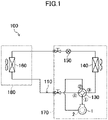
- FIG. 1 is a piping system diagram of an air-conditioning device (100). As illustrated in FIG. 1 , the air-conditioning device (100) includes a refrigerant circuit (110).
- the refrigerant circuit (110) is a closed circuit filled with a refrigerant.
- the refrigerant circuit (110) includes a compressor (1), a four-way switching valve (130), an outdoor heat exchanger (140), an expansion valve (150), and an indoor heat exchanger (160).
- the compressor (1), the four-way switching valve (130), the outdoor heat exchanger (140), and the expansion valve (150) are housed in a casing (not shown) of an outdoor unit (170).
- the indoor heat exchanger (160) is housed in a casing (not shown) of an indoor unit (180).
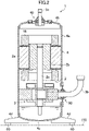
- FIG. 2 illustrates a section of the compressor (1).
- the compressor (1) includes a motor (2), a compression mechanism (3), and a first casing (4).
- the first casing (4) is a closed container that houses the compression mechanism (3) and the motor (2).
- the first casing (4) includes a body (4a), an upper end plate (4b), a lower end plate (4c), and a fitting (4d).
- the body (4a) is a cylindrical member.
- the body (4a) is configured as a metallic plate (a plate material, such as iron).
- the body (4a) can be configured as the metallic plate subjected to so-called "roll forming.”
- the upper and lower end plates (4b) and (4c) are members that close both ends of the body (4a), respectively.
- the upper and lower end plates (4b) and (4c) are made of metal, such as iron.
- the body (4a) and these end plates (4c, 4d) are hermetically fixed together by welding.
- the fitting (4d) is a member for use to install the compressor (1).
- the fitting (4d) is made of metal (such as iron).
- the fitting (4d) is fixed to the lower end plate (4c) by welding.
- the first casing (4) is electrically conductive.
- the compression mechanism (3) compresses a fluid (a refrigerant in this example).
- the compression mechanism (3) may be any one of various fluid machines.
- the compression mechanism (3) may be a rotary compression mechanism, a scroll compression mechanism, or any other type of compression mechanism.
- the compression mechanism (3) is joined to a first suction pipe (3b) (a first pipe).
- the compression mechanism (3) sucks the fluid (refrigerant) from the first suction pipe (3b) to compress the fluid, and discharges the compressed fluid into the first casing (4).
- the refrigerant in the first casing (4) is discharged through a discharge pipe (3c) (another first pipe).
- the discharge pipe (3c) is mounted to the upper end plate (4b).
- the discharge pipe (3c) and the first casing (4) are hermetically connected together through a connector (40), which will be described below.
- the discharge pipe (3c) is made of metal (such as copper).
- the discharge pipe (3c) is electrically conductive.
- the discharge pipe (3c) and the first casing (4) are electrically insulated from each other by the connector (40). An insulating structure provided by the connector (40) will be described below.
- the first suction pipe (3b) is mounted to the body (4a).
- the first suction pipe (3b) and the body (4a) are hermetically connected together through another connector (50), which will be described below.
- the first suction pipe (3b) is made of metal, such as copper.
- the first suction pipe (3b) is electrically conductive.
- the first suction pipe (3b) and the first casing (4) are electrically insulated from each other by the connector (50).
- An insulator (not shown) is provided between the first suction pipe (3b) and the compression mechanism (3).
- the first suction pipe (3b) and the compression mechanism (3) are electrically insulated from each other.
- the motor (2) drives the compression mechanism (3).
- the configuration of the motor (2) is not limited.
- the motor (2) may be any one of various motors.
- the motor (2) may be, for example, an interior permanent magnet motor (a so-called "IPM motor”).
- the motor (2) includes a stator (2a) and a rotor (2b). An air gap is formed between the stator (2a) and the rotor (2b).
- the rotor (2b) includes permanent magnets (not shown).
- the rotor (2b) is coupled to the compression mechanism (3) through a drive shaft (2c).
- the stator (2a) is provided with a coil (16).
- the stator (2a) is fixed to the body (4a) of the first casing (4).
- the stator (2a) and the first casing (4) are electrically continuous.
- the outdoor heat exchanger (140) allows outdoor air and a refrigerant to exchange heat.
- the indoor heat exchanger (160) allows indoor air and a refrigerant to exchange heat.
- the expansion valve (150) is a so-called “electronic expansion valve.”
- the four-way switching valve (130) has first to fourth ports.
- the four-way switching valve (130) is capable of switching between a first state (the state indicated by solid curves in FIG. 2 ) and a second state (the state indicated by broken curves in FIG. 2 ).
- the first port and the third port communicate with each other, and the second port and the fourth port communicate with each other.
- the first port and the fourth port communicate with each other, and the second port and the third port communicate with each other.
- the compressor (1) has a discharge port connected to the first port of the four-way switching valve (130). In the refrigerant circuit (110), the compressor (1) has a suction port connected to the second port of the four-way switching valve (130).
- the outdoor heat exchanger (140), the expansion valve (150), and the indoor heat exchanger (160) in the refrigerant circuit (110) are arranged in this order from the third port toward the fourth port of the four-way switching valve (130).
- the air-conditioning device (100) switches the four-way switching valve (130) to switch between a cooling operation and a heating operation.
- FIG. 3 illustrates an enlarged view of the connector (40).
- the connector (40) includes an eyelet (41), a first insulator (42), a first fixing member (43), and a second fixing member (44).
- the eyelet (41) is a holding member that holds the first insulator (42) and other components.
- the eyelet (41) is a disk-shaped member.
- the eyelet (41) is made of metal.
- the eyelet (41) has a protrusion (41a) at its center.
- the protrusion (41a) has a through hole (41b) at its center.
- the first insulator (42) is an insulative member.
- the first insulator (42) is made of glass.
- the first insulator (42) is fixed to the eyelet (41) in the through hole (41b).
- the first insulator (42) has a through hole (42a).
- the discharge pipe (3c) is fitted into the through hole (42a) of the first insulator (42). In other words, the discharge pipe (3c) is fixed to the eyelet (41) with the first insulator (42) interposed therebetween.
- a method for fixing the eyelet (41), the discharge pipe (3c), and the first insulator (42) together is not limited.
- press-fitting the discharge pipe (3c) into the through hole (42a) of the first insulator (42) enables fixing of the discharge pipe (3c) and the first insulator (42).
- the discharge pipe (3c) and the first insulator (42) may be bonded and fixed to each other.
- Examples of methods of construction to fix the eyelet (41) and the first insulator (42) together also include press-fitting and bonding.
- the first fixing member (43) covers the joint of the discharge pipe (3c) to the first insulator (42).
- the first fixing member (43) is installed to increase hermeticity around the joint to prevent the fluid (refrigerant) from leaking.
- the first fixing member (43) is made of, for example, silicon.
- the first fixing member (43) is a part of the connector (40) outside the first casing (4) (see FIGS. 2 and 3 ).
- the second fixing member (44) is installed to reinforce the area where the discharge pipe (3c) and the first insulator (42) are fixed together.
- the second fixing member (44) is made of, for example, ceramic.
- the second fixing member (44) is a part of the connector (40) inside the first casing (4) (see FIGS. 2 and 3 ).
- the second fixing member (44) is fitted to an end of the discharge pipe (3c).
- the eyelet (41) has its outer periphery hermetically fixed to the first casing (4) (see FIGS. 2 and 3 ). Specifically, the eyelet (41) and the first casing (4) are brazed together.
- the first suction pipe (3b) and the first casing (4) are electrically insulated from each other by the connector (50).
- the connector (50) also includes an eyelet (41), a first insulator (42), a first fixing member (43), and a second fixing member (44).
- the connector (50) includes members similar to those of the connector (40). In other words, a structure for insulating the first suction pipe (3b) and the first casing (4) from each other is similar to the structure for insulating the discharge pipe (3c) and the first casing (4) from each other.
- the first casing (4) and a target to which the first casing (4) is fitted are also electrically insulated from each other.
- the installation destination of the first casing (4) is the casing (not shown) of the outdoor unit (170) of the air-conditioning device (100).
- the fitting (4d) is provided with a second insulator (60).
- the second insulator (60) electrically insulates the installation destination of the first casing (4) from the fitting (4d).
- the second insulator (60) is made of an insulative material. Examples of the material of the second insulator (60) include rubber, glass, resin, and ceramic.
- a power converter (not shown) including an inverter circuit is used for power supply.
- the inverter circuit has its switching elements repeatedly turned on and off. The on/off operations of the switching elements may cause noise.
- the noise generated in the power converter is transmitted to the motor (2) via a power supply wire connecting the power converter and the motor (2) together.
- noise is transmitted to a casing of the compressor mainly through a stray capacitance formed between a stator and a coil of a motor.
- the noise transmitted to the casing may leak, as noise, to the outside of the device through pipes, pipe fittings, and any other members.
- the noise is insulated by the first insulator (42) of the connector (40) and the first insulator (42) of the connector (50). This prevents the noise from being transmitted to the pipes (the first suction pipe (3b), the discharge pipe (3c)).
- the noise transmitted to the first casing (4) is insulated by the second insulator (60). This prevents the noise from being transmitted to the installation destination (the casing of the outdoor unit (170)).
- the present disclosure is directed to a compressor (1) configured to compress a fluid.
- the compressor (1) includes an electrically conductive first casing (4) and an electrically conductive first pipe (3b, 3c).
- the first pipe (3b, 3c) is fixed to the first casing (4) with a first insulator (42) interposed therebetween.
- the pipes (3b, 3c) for the compressor (1) are electrically insulated from the compressor (1) without causing leakage of a refrigerant.
- the casing of the outdoor unit (170) and the compressor (1) are also electrically insulated from each other.
- noise e.g., common-mode noise
- the noise should be addressed in an area as close to the source of the noise as possible. If noise is unaddressed in a compressor, pipes may be insulated at all of their respective fixation portions, for example, to address the noise. The fixed portions are not always close to the compressor (motor).
- insulation is performed at a position close to the motor (2), which is the source of noise.
- This embodiment can be said to ideally address noise.
- the number of portions of the pipes to be insulated is less than if the pipes are insulated at all of their respective fixed portions.
- the connector (40) will be described below. The following variations are also applicable to the connector (50).
- the first fixing member (43) (silicon or any other material) is omitted as appropriate for illustration purpose.
- FIG. 4 illustrates a first variation of the connector (40).
- a protrusion (41a) of an eyelet (41) is provided with another protrusion (41c).
- the protrusion (41c) is cylindrical.
- the protrusion (41c) protrudes in the same direction as that of the protrusion (41a).
- a first insulator (42) is provided in the protrusion (41c). In the first variation, the first insulator (42) is held by the protrusion (41c). In the first variation, the strength of a portion of the eyelet (41) holding the first insulator (42) is improved.
- FIG. 5 illustrates a second variation of the connector (40).
- a protrusion (41a) of an eyelet (41) is provided with another protrusion (41d).
- the protrusion (41d) is cylindrical.
- the protrusion (41d) protrudes in a direction opposite to the direction of the protrusion (41a).
- a first insulator (42) is provided in the protrusion (41d).
- the strength of a portion of the eyelet (41) holding the first insulator (42) is improved.
- FIG. 6 illustrates a third variation of the connector (40).
- a protrusion (41a) of an eyelet (41) is provided with another protrusion (41e).
- the protrusion (41e) is cylindrical.
- the protrusion (41e) protrudes in both the same direction as, and a direction opposite to, the direction of the protrusion (41a).
- a first insulator (42) is provided in the protrusion (41d).
- the strength of a portion of the eyelet (41) holding the first insulator (42) is improved.
- the strength of the portion of the eyelet (41) holding the first insulator (42) is improved.
- the second fixing member (44) (ceramic or any other material) can be omitted depending on applications.
- the second fixing member (44) may be provided.
- FIG. 7 illustrates a fourth variation of the connector (40).
- an eyelet (41) of the fourth variation of the connector (40) is fixed to a pipe (3b, 3c), and a first insulator (42) is fixed to a first casing (4).
- This configuration also allows the pipe (3b, 3c) and the first casing (4) to be electrically insulated from each other.
- FIG. 8 is a cross-sectional view of a compressor unit (90) according to a second embodiment.
- the compressor unit (90) is installed in a casing of an outdoor unit (170).
- the compressor unit (90) is electrically insulated from the casing of the outdoor unit (170).
- the compressor unit (90) includes a compressor (1) and an accumulator (70).
- the compressor (1) is obtained by partially modifying the compressor (1) described in the first embodiment.
- the compressor (1) of this embodiment is distinct from the compressor (1) of the first embodiment in that no insulator is provided between a first suction pipe (3b) and a compression mechanism (3).
- the compressor (1) of this embodiment is distinct from the compressor (1) of the first embodiment also in that the first suction pipe (3b) and a first casing (4) are not electrically insulated from each other.
- the accumulator (70) temporarily stores a fluid (a refrigerant) sucked by the compressor (1).
- the accumulator (70) separates a liquid material contained in a gaseous fluid (a refrigerant) into gas and liquid.
- the liquid material is a liquid refrigerant, lubricant, or any other similar material.
- the accumulator (70) includes a second casing (71), an outlet pipe (72), a fixing member (73), a second suction pipe (3d) (a second pipe), and a connector (80).
- the second casing (71) is a cylindrical closed container.
- the second casing (71) is vertically oriented.
- the second casing (71) is made of metal (such as iron).
- the second casing (71) is electrically conductive.
- the outlet pipe (72) is made of metal (such as copper).
- the outlet pipe (72) is electrically conductive.
- One end of the outlet pipe (72) is inserted through a through hole of a lower portion of the second casing (71) into the second casing (71) (see FIG. 8 ).
- the one end of the outlet pipe (72) extends upward in the second casing (71).
- the outlet pipe (72) and the second casing (71) are hermetically fixed together in the through hole by welding.
- the second casing (71) and the outlet pipe (72) are electrically continuous.
- the other end of the outlet pipe (72) is hermetically fixed to the first suction pipe (3b) by welding.
- the outlet pipe (72) and the first suction pipe (3b) are electrically continuous.
- the fixing member (73) is a member configured to fasten the second casing (71) to a target to which the second casing (71) is fitted.
- the target to which the second casing (71) is fitted is the first casing (4).
- the fixing member (73) is made of metal (such as iron).
- the fixing member (73) is electrically conductive.
- the second casing (71) and the first casing (4) are electrically continuous.
- a fastening structure provided by the fixing member (73) may be any one of various structures.
- the fixing member (73) is fixed to each of the first and second casings (4) and (71) by welding.
- the fixing member (73) may include a plurality of parts. Specifically, a support base (metal) is provided on the outer peripheral surface of the first casing (4).
- the support base is a member for fixing the second casing (71). The first casing (4) and the support base are fixed together by welding.
- a fixing belt configured to fix the outer peripheral surface (side surface) of the second casing (71) to the support base.
- the fixing belt is a metallic plate member (belt-shaped member).
- the fixing belt is wound around the outer peripheral surface of the second casing (71), and has both ends fitted to the support base.
- the fixing belt is fastened to the support base through a fastening member, such as a bolt. This configuration also allows the first and second casings (4) and (71) to be electrically continuous.
- the accumulator (70) can also be held by the pipes (the first suction pipe (3b), the outlet pipe (72)) between the compressor (1) and the accumulator (70). If the accumulator (70) can be reliably held by the first suction pipe (3b) and the outlet pipe (72), the fixing member (73) may be omitted.
- a structure that holds the accumulator (70) may be any one of various structures.
- the accumulator (70) needs to be prevented from being electrically continuous with the casing of the outdoor unit (170).
- the second suction pipe (3d) is made of metal (such as copper).
- the second suction pipe (3d) is electrically conductive.
- the second suction pipe (3d) is provided on an upper portion of the second casing (71).
- the second suction pipe (3d) and the second casing (71) are electrically insulated from each other by the connector (80).
- the connector (80) includes an eyelet (41), a third insulator (82), a first fixing member (43), and a second fixing member (44).
- the third insulator (82) of the connector (80) is literally different from the first insulator (42) of the connector (40).
- the first and third insulators (42) and (82) have the same configuration. Also in this embodiment, the third insulator (82) is made of glass. The third insulator (82) is insulative.
- the overall structure of the connector (80) can be understood on referring to FIG. 3 .
- the eyelet (41) has its outer periphery hermetically fixed to the second casing (71) (see FIG. 7 ).
- the eyelet (41) and the second casing (71) are brazed together.
- the connector (80) can have any one of various configurations described in the variations of the embodiment (see FIGS. 4 to 7 ).
- the foregoing configuration allows the first and second casings (4) and (71) of the compressor unit (90) to be electrically continuous.
- the discharge pipe (3c) and the first casing (4) are electrically insulated from each other.
- the second suction pipe (3d) and the second casing (71) are electrically insulated from each other.
- the first casing (4) is insulated from an installation destination (the casing of the outdoor unit (170)) by the second insulator (60).
- a pipe for a compressor can be electrically insulated from the compressor without causing leakage of a refrigerant.
- a predetermined stress is produced on a coupling portion configured as the pipe during operation of the compressor (1) or in a similar situation.
- a predetermined stress is produced on the first suction pipe (3b).
- the coupling portion between the compressor (1) and the accumulator (70) needs to have a sufficiently high strength.
- the first suction pipe (3b) does not need to be insulated from the compression mechanism (3), and does not need to be electrically insulated from the second casing (71).
- the structure of the coupling portion of this embodiment has a high degree of design freedom. This embodiment makes it easy for the coupling portion to have a sufficiently high strength.
- the material of the first insulator (42) and the material of the third insulator (82) are not limited to glass.
- Examples of the material of the first and third insulators (42) and (82) include resin and ceramic.
- the connector (40, 50) may be used to connect a pipe except the discharge pipe (3c) and the first and second suction pipes (3b) and (3d) to an object.
- the eyelet (41) may be omitted.
- the first insulator (42) may be directly connected to the first casing (4) while being directly connected to the associated pipe (3b, 3c).
- the third insulator (82) and the second casing (71) may be directly connected together.
- the present disclosure is useful for a compressor and a compressor unit.
Landscapes
- Engineering & Computer Science (AREA)
- General Engineering & Computer Science (AREA)
- Mechanical Engineering (AREA)
- Compressor (AREA)
Abstract
Description
- The present disclosure relates to a compressor and a compressor unit.
- Some air-conditioning devices include a pipe connected to a compressor and made of an insulating material (see, for example, Patent Document 1). In an example of the patent document described above, a rubber hose is used as an insulator.
- Patent Document 1:
Japanese Unexamined Patent Publication No. H09-002050 - The rubber hose for use in the patent document described above may lead to leakage of a refrigerant.
- It is an object of the present disclosure to electrically insulate a pipe for a compressor from the compressor without causing leakage of a refrigerant.
- A first aspect of the present disclosure is directed to a compressor configured to compress a fluid. The compressor includes:
- a first casing (4) being electrically conductive; and
- at least one first pipe (3b, 3c) being electrically conductive.
- The at least one first pipe (3b, 3c) is fixed to the first casing (4) with a first insulator (42) interposed therebetween.
- The first aspect allows the pipe (3b, 3c) and the first casing (4) to be electrically insulated from each other.
- A second aspect of the present disclosure is an embodiment of the first aspect. In the second aspect, the compressor further includes:
a holding member (41) fixed to the first casing (4). - The first insulator (42) is fixed to the holding member (41), and
the at least one first pipe (3b, 3c) is fixed to the holding member (41) with the first insulator (42) interposed therebetween. - According to the second aspect, the first insulator (42) is fixed to the holding member (41).
- A third aspect of the present disclosure is an embodiment of the first aspect. In the third aspect, the compressor further includes:
a holding member (41) fixed to the at least one first pipe (3b, 3c). - The first insulator (42) is fixed to the first casing (4), and
the first casing (4) is fixed to the holding member (41) with the first insulator (42) interposed therebetween. - According to the third aspect, the first insulator (42) is fixed to the first casing (4).
- A fourth aspect of the present disclosure is an embodiment of any one of the first to third aspects. In the fourth aspect,
he first insulator (42) is made of any one of glass, resin, or ceramic. - A fifth aspect of the present disclosure is an embodiment of any one of the first to fourth aspects. In the fifth aspect,
- the at least one first pipe (3b, 3c) comprises a plurality of first pipes (3b, 3c),
- one of the first pipes (3b, 3c) is a first suction pipe (3b) through which the fluid is to be sucked, and
- According to the fifth aspect, the first suction pipe (3b) and the discharge pipe (3c) are both insulated from the first casing (4).
- A sixth aspect of the present disclosure is an embodiment of any one of the first to fifth aspects. In the sixth aspect,
- the first casing (4) includes a fitting (4d) configured to install the first casing (4), and
- the fitting (4d) is provided with a second insulator (60) configured to electrically insulate an installation destination of the first casing (4) from the fitting (4d).
- According to the sixth aspect, a target to which the compressor is fitted is insulated from the first casing (4).
- A seventh aspect of the present disclosure is directed to a compressor unit. The compressor unit includes:
- the compressor (1) of any one of the first to fourth and sixth aspects;
- a second casing (71) being electrically conductive; and
- a second pipe (3d) being electrically conductive.
- The second casing (71) is connected to the first casing (4).
- The second pipe (3d) is fixed to the second casing (71) with a third insulator (82) interposed therebetween.
- An eighth aspect of the present disclosure is an embodiment of the seventh aspect. In the eighth aspect,
- the at least one first pipe (3b, 3c) is a discharge pipe through which the fluid is to be discharged, and
- the second pipe (3d) is a suction pipe through which the fluid is to be sucked.
- A ninth aspect of the present disclosure is an embodiment of the seventh or eighth aspect. In the ninth aspect,
the third insulator (82) is made of any one of glass, resin, or ceramic. -
-
FIG. 1 is a piping system diagram of an air-conditioning device. -
FIG. 2 is a cross-sectional view of a compressor. -
FIG. 3 is an enlarged view of a connector. -
FIG. 4 illustrates a first variation of the connector. -
FIG. 5 illustrates a second variation of the connector. -
FIG. 6 illustrates a third variation of the connector. -
FIG. 7 illustrates a fourth variation of the connector. -
FIG. 8 is a cross-sectional view of a compressor unit according to a second embodiment. - The present disclosure describes a compressor for an air-conditioning device.
FIG. 1 is a piping system diagram of an air-conditioning device (100). As illustrated inFIG. 1 , the air-conditioning device (100) includes a refrigerant circuit (110). - The refrigerant circuit (110) is a closed circuit filled with a refrigerant. The refrigerant circuit (110) includes a compressor (1), a four-way switching valve (130), an outdoor heat exchanger (140), an expansion valve (150), and an indoor heat exchanger (160).
- The compressor (1), the four-way switching valve (130), the outdoor heat exchanger (140), and the expansion valve (150) are housed in a casing (not shown) of an outdoor unit (170). The indoor heat exchanger (160) is housed in a casing (not shown) of an indoor unit (180).
-
FIG. 2 illustrates a section of the compressor (1). The compressor (1) includes a motor (2), a compression mechanism (3), and a first casing (4). - The first casing (4) is a closed container that houses the compression mechanism (3) and the motor (2). The first casing (4) includes a body (4a), an upper end plate (4b), a lower end plate (4c), and a fitting (4d).
- The body (4a) is a cylindrical member. The body (4a) is configured as a metallic plate (a plate material, such as iron). For example, the body (4a) can be configured as the metallic plate subjected to so-called "roll forming."
- The upper and lower end plates (4b) and (4c) are members that close both ends of the body (4a), respectively. The upper and lower end plates (4b) and (4c) are made of metal, such as iron. The body (4a) and these end plates (4c, 4d) are hermetically fixed together by welding.
- The fitting (4d) is a member for use to install the compressor (1). The fitting (4d) is made of metal (such as iron). The fitting (4d) is fixed to the lower end plate (4c) by welding. As can be seen from the foregoing description, the first casing (4) is electrically conductive.
- The compression mechanism (3) compresses a fluid (a refrigerant in this example). The compression mechanism (3) may be any one of various fluid machines. For example, the compression mechanism (3) may be a rotary compression mechanism, a scroll compression mechanism, or any other type of compression mechanism.
- The compression mechanism (3) is joined to a first suction pipe (3b) (a first pipe). The compression mechanism (3) sucks the fluid (refrigerant) from the first suction pipe (3b) to compress the fluid, and discharges the compressed fluid into the first casing (4). The refrigerant in the first casing (4) is discharged through a discharge pipe (3c) (another first pipe).
- The discharge pipe (3c) is mounted to the upper end plate (4b). The discharge pipe (3c) and the first casing (4) are hermetically connected together through a connector (40), which will be described below.
- The discharge pipe (3c) is made of metal (such as copper). The discharge pipe (3c) is electrically conductive. The discharge pipe (3c) and the first casing (4) are electrically insulated from each other by the connector (40). An insulating structure provided by the connector (40) will be described below.
- The first suction pipe (3b) is mounted to the body (4a). The first suction pipe (3b) and the body (4a) are hermetically connected together through another connector (50), which will be described below.
- The first suction pipe (3b) is made of metal, such as copper. The first suction pipe (3b) is electrically conductive. The first suction pipe (3b) and the first casing (4) are electrically insulated from each other by the connector (50).
- An insulator (not shown) is provided between the first suction pipe (3b) and the compression mechanism (3). In other words, the first suction pipe (3b) and the compression mechanism (3) are electrically insulated from each other.
- The motor (2) drives the compression mechanism (3). The configuration of the motor (2) is not limited. The motor (2) may be any one of various motors. The motor (2) may be, for example, an interior permanent magnet motor (a so-called "IPM motor").
- The motor (2) includes a stator (2a) and a rotor (2b). An air gap is formed between the stator (2a) and the rotor (2b). The rotor (2b) includes permanent magnets (not shown). The rotor (2b) is coupled to the compression mechanism (3) through a drive shaft (2c).
- The stator (2a) is provided with a coil (16). The stator (2a) is fixed to the body (4a) of the first casing (4). The stator (2a) and the first casing (4) are electrically continuous.
- The outdoor heat exchanger (140) allows outdoor air and a refrigerant to exchange heat. The indoor heat exchanger (160) allows indoor air and a refrigerant to exchange heat. The expansion valve (150) is a so-called "electronic expansion valve."
- The four-way switching valve (130) has first to fourth ports. The four-way switching valve (130) is capable of switching between a first state (the state indicated by solid curves in
FIG. 2 ) and a second state (the state indicated by broken curves inFIG. 2 ). - In the first state, the first port and the third port communicate with each other, and the second port and the fourth port communicate with each other. In the second state, the first port and the fourth port communicate with each other, and the second port and the third port communicate with each other.
- In the refrigerant circuit (110), the compressor (1) has a discharge port connected to the first port of the four-way switching valve (130). In the refrigerant circuit (110), the compressor (1) has a suction port connected to the second port of the four-way switching valve (130).
- The outdoor heat exchanger (140), the expansion valve (150), and the indoor heat exchanger (160) in the refrigerant circuit (110) are arranged in this order from the third port toward the fourth port of the four-way switching valve (130). The air-conditioning device (100) switches the four-way switching valve (130) to switch between a cooling operation and a heating operation.
- As described above, the discharge pipe (3c) and the first casing (4) are electrically insulated from each other by the connector (40).
FIG. 3 illustrates an enlarged view of the connector (40). The connector (40) includes an eyelet (41), a first insulator (42), a first fixing member (43), and a second fixing member (44). - The eyelet (41) is a holding member that holds the first insulator (42) and other components. The eyelet (41) is a disk-shaped member. The eyelet (41) is made of metal. The eyelet (41) has a protrusion (41a) at its center. The protrusion (41a) has a through hole (41b) at its center.
- The first insulator (42) is an insulative member. In this embodiment, the first insulator (42) is made of glass. The first insulator (42) is fixed to the eyelet (41) in the through hole (41b).
- The first insulator (42) has a through hole (42a). The discharge pipe (3c) is fitted into the through hole (42a) of the first insulator (42). In other words, the discharge pipe (3c) is fixed to the eyelet (41) with the first insulator (42) interposed therebetween.
- A method for fixing the eyelet (41), the discharge pipe (3c), and the first insulator (42) together is not limited. For example, press-fitting the discharge pipe (3c) into the through hole (42a) of the first insulator (42) enables fixing of the discharge pipe (3c) and the first insulator (42). The discharge pipe (3c) and the first insulator (42) may be bonded and fixed to each other. Examples of methods of construction to fix the eyelet (41) and the first insulator (42) together also include press-fitting and bonding.
- The first fixing member (43) covers the joint of the discharge pipe (3c) to the first insulator (42). The first fixing member (43) is installed to increase hermeticity around the joint to prevent the fluid (refrigerant) from leaking. The first fixing member (43) is made of, for example, silicon. The first fixing member (43) is a part of the connector (40) outside the first casing (4) (see
FIGS. 2 and3 ). - The second fixing member (44) is installed to reinforce the area where the discharge pipe (3c) and the first insulator (42) are fixed together. The second fixing member (44) is made of, for example, ceramic. The second fixing member (44) is a part of the connector (40) inside the first casing (4) (see
FIGS. 2 and3 ). The second fixing member (44) is fitted to an end of the discharge pipe (3c). - The eyelet (41) has its outer periphery hermetically fixed to the first casing (4) (see
FIGS. 2 and3 ). Specifically, the eyelet (41) and the first casing (4) are brazed together. - As described above, the first suction pipe (3b) and the first casing (4) are electrically insulated from each other by the connector (50). The connector (50) also includes an eyelet (41), a first insulator (42), a first fixing member (43), and a second fixing member (44). The connector (50) includes members similar to those of the connector (40). In other words, a structure for insulating the first suction pipe (3b) and the first casing (4) from each other is similar to the structure for insulating the discharge pipe (3c) and the first casing (4) from each other.
- The first casing (4) and a target to which the first casing (4) is fitted (installation destination) are also electrically insulated from each other. In this embodiment, the installation destination of the first casing (4) is the casing (not shown) of the outdoor unit (170) of the air-conditioning device (100).
- The fitting (4d) is provided with a second insulator (60). The second insulator (60) electrically insulates the installation destination of the first casing (4) from the fitting (4d). The second insulator (60) is made of an insulative material. Examples of the material of the second insulator (60) include rubber, glass, resin, and ceramic.
- During operation of the compressor (1), electric power is supplied to the motor (2). Suppose that, in this embodiment, a power converter (not shown) including an inverter circuit is used for power supply. The inverter circuit has its switching elements repeatedly turned on and off. The on/off operations of the switching elements may cause noise. The noise generated in the power converter is transmitted to the motor (2) via a power supply wire connecting the power converter and the motor (2) together.
- In a compressor where noise is unaddressed, noise is transmitted to a casing of the compressor mainly through a stray capacitance formed between a stator and a coil of a motor. The noise transmitted to the casing may leak, as noise, to the outside of the device through pipes, pipe fittings, and any other members.
- To address this problem, in this embodiment, even if noise is transmitted to the first casing (4), the noise is insulated by the first insulator (42) of the connector (40) and the first insulator (42) of the connector (50). This prevents the noise from being transmitted to the pipes (the first suction pipe (3b), the discharge pipe (3c)). The noise transmitted to the first casing (4) is insulated by the second insulator (60). This prevents the noise from being transmitted to the installation destination (the casing of the outdoor unit (170)).
- In summary, the present disclosure is directed to a compressor (1) configured to compress a fluid. The compressor (1) includes an electrically conductive first casing (4) and an electrically conductive first pipe (3b, 3c). The first pipe (3b, 3c) is fixed to the first casing (4) with a first insulator (42) interposed therebetween.
- As described above, in this embodiment, the pipes (3b, 3c) for the compressor (1) are electrically insulated from the compressor (1) without causing leakage of a refrigerant. The casing of the outdoor unit (170) and the compressor (1) are also electrically insulated from each other. In this embodiment, noise (e.g., common-mode noise) issuing from the compressor (1) can be reduced.
- Ideally, the noise should be addressed in an area as close to the source of the noise as possible. If noise is unaddressed in a compressor, pipes may be insulated at all of their respective fixation portions, for example, to address the noise. The fixed portions are not always close to the compressor (motor).
- In contrast, in this embodiment, insulation is performed at a position close to the motor (2), which is the source of noise. This embodiment can be said to ideally address noise. Furthermore, in this embodiment, the number of portions of the pipes to be insulated is less than if the pipes are insulated at all of their respective fixed portions.
- Variations of the connector (40) will be described below. The following variations are also applicable to the connector (50). In the drawings illustrating the following variations, the first fixing member (43) (silicon or any other material) is omitted as appropriate for illustration purpose.
-
FIG. 4 illustrates a first variation of the connector (40). In the first variation, a protrusion (41a) of an eyelet (41) is provided with another protrusion (41c). The protrusion (41c) is cylindrical. The protrusion (41c) protrudes in the same direction as that of the protrusion (41a). - A first insulator (42) is provided in the protrusion (41c). In the first variation, the first insulator (42) is held by the protrusion (41c). In the first variation, the strength of a portion of the eyelet (41) holding the first insulator (42) is improved.
-
FIG. 5 illustrates a second variation of the connector (40). In the second variation, a protrusion (41a) of an eyelet (41) is provided with another protrusion (41d). The protrusion (41d) is cylindrical. The protrusion (41d) protrudes in a direction opposite to the direction of the protrusion (41a). - A first insulator (42) is provided in the protrusion (41d). In the second variation, the strength of a portion of the eyelet (41) holding the first insulator (42) is improved.
-
FIG. 6 illustrates a third variation of the connector (40). In the third variation, a protrusion (41a) of an eyelet (41) is provided with another protrusion (41e). The protrusion (41e) is cylindrical. The protrusion (41e) protrudes in both the same direction as, and a direction opposite to, the direction of the protrusion (41a). - A first insulator (42) is provided in the protrusion (41d). In the third variation, the strength of a portion of the eyelet (41) holding the first insulator (42) is improved.
- In each of the first, second, and third variations, the strength of the portion of the eyelet (41) holding the first insulator (42) is improved. Thus, the second fixing member (44) (ceramic or any other material) can be omitted depending on applications. Naturally, in each of the first to third variations, the second fixing member (44) may be provided.
-
FIG. 7 illustrates a fourth variation of the connector (40). As illustrated inFIG. 7 , an eyelet (41) of the fourth variation of the connector (40) is fixed to a pipe (3b, 3c), and a first insulator (42) is fixed to a first casing (4). This configuration also allows the pipe (3b, 3c) and the first casing (4) to be electrically insulated from each other. -
FIG. 8 is a cross-sectional view of a compressor unit (90) according to a second embodiment. The compressor unit (90) is installed in a casing of an outdoor unit (170). The compressor unit (90) is electrically insulated from the casing of the outdoor unit (170). - The compressor unit (90) includes a compressor (1) and an accumulator (70). The compressor (1) is obtained by partially modifying the compressor (1) described in the first embodiment. The compressor (1) of this embodiment is distinct from the compressor (1) of the first embodiment in that no insulator is provided between a first suction pipe (3b) and a compression mechanism (3). The compressor (1) of this embodiment is distinct from the compressor (1) of the first embodiment also in that the first suction pipe (3b) and a first casing (4) are not electrically insulated from each other.
- The accumulator (70) temporarily stores a fluid (a refrigerant) sucked by the compressor (1). The accumulator (70) separates a liquid material contained in a gaseous fluid (a refrigerant) into gas and liquid. The liquid material is a liquid refrigerant, lubricant, or any other similar material.
- The accumulator (70) includes a second casing (71), an outlet pipe (72), a fixing member (73), a second suction pipe (3d) (a second pipe), and a connector (80).
- The second casing (71) is a cylindrical closed container. The second casing (71) is vertically oriented. The second casing (71) is made of metal (such as iron). The second casing (71) is electrically conductive.
- The outlet pipe (72) is made of metal (such as copper). The outlet pipe (72) is electrically conductive.
- One end of the outlet pipe (72) is inserted through a through hole of a lower portion of the second casing (71) into the second casing (71) (see
FIG. 8 ). The one end of the outlet pipe (72) extends upward in the second casing (71). - The outlet pipe (72) and the second casing (71) are hermetically fixed together in the through hole by welding. The second casing (71) and the outlet pipe (72) are electrically continuous. The other end of the outlet pipe (72) is hermetically fixed to the first suction pipe (3b) by welding. The outlet pipe (72) and the first suction pipe (3b) are electrically continuous.
- The fixing member (73) is a member configured to fasten the second casing (71) to a target to which the second casing (71) is fitted. In this embodiment, the target to which the second casing (71) is fitted is the first casing (4). The fixing member (73) is made of metal (such as iron). The fixing member (73) is electrically conductive. The second casing (71) and the first casing (4) are electrically continuous.
- A fastening structure provided by the fixing member (73) may be any one of various structures. For example, the fixing member (73) is fixed to each of the first and second casings (4) and (71) by welding.
- Although not shown, the fixing member (73) may include a plurality of parts. Specifically, a support base (metal) is provided on the outer peripheral surface of the first casing (4). The support base is a member for fixing the second casing (71). The first casing (4) and the support base are fixed together by welding.
- A fixing belt configured to fix the outer peripheral surface (side surface) of the second casing (71) to the support base is provided. In this example, the fixing belt is a metallic plate member (belt-shaped member). The fixing belt is wound around the outer peripheral surface of the second casing (71), and has both ends fitted to the support base. The fixing belt is fastened to the support base through a fastening member, such as a bolt. This configuration also allows the first and second casings (4) and (71) to be electrically continuous.
- The accumulator (70) can also be held by the pipes (the first suction pipe (3b), the outlet pipe (72)) between the compressor (1) and the accumulator (70). If the accumulator (70) can be reliably held by the first suction pipe (3b) and the outlet pipe (72), the fixing member (73) may be omitted.
- As can be seen, a structure that holds the accumulator (70) may be any one of various structures. In the structure that holds the accumulator (70), the accumulator (70) needs to be prevented from being electrically continuous with the casing of the outdoor unit (170).
- The second suction pipe (3d) is made of metal (such as copper). The second suction pipe (3d) is electrically conductive. The second suction pipe (3d) is provided on an upper portion of the second casing (71). The second suction pipe (3d) and the second casing (71) are electrically insulated from each other by the connector (80).
- The connector (80) includes an eyelet (41), a third insulator (82), a first fixing member (43), and a second fixing member (44). The third insulator (82) of the connector (80) is literally different from the first insulator (42) of the connector (40).
- This difference is made by modifying the name of the member for illustration purpose. The first and third insulators (42) and (82) have the same configuration. Also in this embodiment, the third insulator (82) is made of glass. The third insulator (82) is insulative. The overall structure of the connector (80) can be understood on referring to
FIG. 3 . - Also in this embodiment, the eyelet (41) has its outer periphery hermetically fixed to the second casing (71) (see
FIG. 7 ). The eyelet (41) and the second casing (71) are brazed together. The connector (80) can have any one of various configurations described in the variations of the embodiment (seeFIGS. 4 to 7 ). - The foregoing configuration allows the first and second casings (4) and (71) of the compressor unit (90) to be electrically continuous. The discharge pipe (3c) and the first casing (4) are electrically insulated from each other. The second suction pipe (3d) and the second casing (71) are electrically insulated from each other. The first casing (4) is insulated from an installation destination (the casing of the outdoor unit (170)) by the second insulator (60).
- No path allows the first casing (4) to be electrically continuous with the exterior of the compressor unit (90). In the compressor unit (90), noise generated in a motor (2) and then transmitted to the first casing (4) would not be transmitted to the exterior of the compressor unit (90).
- According to this embodiment, a pipe for a compressor can be electrically insulated from the compressor without causing leakage of a refrigerant.
- If the first casing (4) and the accumulator (70) are coupled together through a pipe, a predetermined stress is produced on a coupling portion configured as the pipe during operation of the compressor (1) or in a similar situation. In this embodiment, a predetermined stress is produced on the first suction pipe (3b).
- Thus, the coupling portion between the compressor (1) and the accumulator (70) needs to have a sufficiently high strength. In this embodiment, the first suction pipe (3b) does not need to be insulated from the compression mechanism (3), and does not need to be electrically insulated from the second casing (71). In other words, the structure of the coupling portion of this embodiment has a high degree of design freedom. This embodiment makes it easy for the coupling portion to have a sufficiently high strength.
- The material of the first insulator (42) and the material of the third insulator (82) are not limited to glass. Examples of the material of the first and third insulators (42) and (82) include resin and ceramic.
- The connector (40, 50) may be used to connect a pipe except the discharge pipe (3c) and the first and second suction pipes (3b) and (3d) to an object.
- The eyelet (41) may be omitted. Specifically, the first insulator (42) may be directly connected to the first casing (4) while being directly connected to the associated pipe (3b, 3c). Likewise, the third insulator (82) and the second casing (71) may be directly connected together.
- While the embodiments and variations thereof have been described above, it will be understood that various changes in form and details may be made without departing from the spirit and scope of the claims. The embodiments and the variations thereof may be combined and replaced with each other without deteriorating intended functions of the present disclosure.
- As can be seen from the foregoing description, the present disclosure is useful for a compressor and a compressor unit.
-
- 1
- Compressor
- 3b
- First Suction Pipe (First Pipe)
- 3c
- Discharge Pipe (First Pipe)
- 3d
- Second Suction Pipe (Second Pipe)
- 4
- First Casing
- 4d
- Fitting
- 41
- Eyelet (Holding Member)
- 42
- First Insulator
- 60
- Second Insulator
- 71
- Second Casing
- 82
- Third Insulator
- 90
- Compressor Unit
Claims (9)
- A compressor configured to compress a fluid, the compressor comprising:a first casing (4) being electrically conductive; andat least one first pipe (3b, 3c) being electrically conductive,the at least one first pipe (3b, 3c) being fixed to the first casing (4) with a first insulator (42) interposed therebetween.
- The compressor of claim 1, further comprising:a holding member (41) fixed to the first casing (4), whereinthe first insulator (42) is fixed to the holding member (41), andthe at least one first pipe (3b, 3c) is fixed to the holding member (41) with the first insulator (42) interposed therebetween.
- The compressor of claim 1, further comprising:a holding member (41) fixed to the at least one first pipe (3b, 3c), whereinthe first insulator (42) is fixed to the first casing (4), andthe first casing (4) is fixed to the holding member (41) with the first insulator (42) interposed therebetween.
- The compressor of any one of claims 1 to 3, wherein
the first insulator (42) is made of any one of glass, resin, or ceramic. - The compressor of any one of claims 1 to 4, whereinthe at least one first pipe (3b, 3c) comprises a plurality of first pipes (3b, 3c),one of the first pipes (3b, 3c) is a first suction pipe (3b) through which the fluid is to be sucked, andanother one of the first pipes (3b, 3c) is a discharge pipe (3c) through which the fluid is to be discharged.
- The compressor of any one of claims 1 to 5, whereinthe first casing (4) includes a fitting (4d) configured to install the first casing (4), andthe fitting (4d) is provided with a second insulator (60) configured to electrically insulate an installation destination of the first casing (4) from the fitting (4d).
- A compressor unit comprising:the compressor (1) of any one of claims 1 to 4 and 6;a second casing (71) being electrically conductive; anda second pipe (3d) being electrically conductive,the second casing (71) being connected to the first casing (4),the second pipe (3d) being fixed to the second casing (71) with a third insulator (82) interposed therebetween.
- The compressor unit of claim 7, whereinthe at least one first pipe (3b, 3c) is a discharge pipe through which the fluid is to be discharged, andthe second pipe (3d) is a suction pipe through which the fluid is to be sucked.
- The compressor unit of claim 7 or 8, wherein the third insulator (82) is made of any one of glass, resin, or ceramic.
Applications Claiming Priority (2)
| Application Number | Priority Date | Filing Date | Title |
|---|---|---|---|
| JP2019221385 | 2019-12-06 | ||
| PCT/JP2020/042641 WO2021111853A1 (en) | 2019-12-06 | 2020-11-16 | Compressor and compressor unit |
Publications (3)
| Publication Number | Publication Date |
|---|---|
| EP4050212A1 true EP4050212A1 (en) | 2022-08-31 |
| EP4050212A4 EP4050212A4 (en) | 2023-11-08 |
| EP4050212B1 EP4050212B1 (en) | 2026-05-06 |
Family
ID=76221585
Family Applications (1)
| Application Number | Title | Priority Date | Filing Date |
|---|---|---|---|
| EP20896655.6A Active EP4050212B1 (en) | 2019-12-06 | 2020-11-16 | Compressor and compressor unit |
Country Status (5)
| Country | Link |
|---|---|
| US (1) | US12338921B2 (en) |
| EP (1) | EP4050212B1 (en) |
| JP (1) | JP6923062B2 (en) |
| CN (1) | CN114729631A (en) |
| WO (1) | WO2021111853A1 (en) |
Citations (1)
| Publication number | Priority date | Publication date | Assignee | Title |
|---|---|---|---|---|
| JPH092050A (en) | 1995-06-26 | 1997-01-07 | Matsushita Electric Ind Co Ltd | Automotive air conditioners |
Family Cites Families (12)
| Publication number | Priority date | Publication date | Assignee | Title |
|---|---|---|---|---|
| FR2655389B1 (en) * | 1989-12-01 | 1994-05-27 | Unite Hermetique | HERMETIC MOTOR COMPRESSOR WITH QUIET OPERATION. |
| JPH045486A (en) * | 1990-04-23 | 1992-01-09 | Sanyo Electric Co Ltd | Closed compressor |
| JP2963801B2 (en) * | 1991-11-06 | 1999-10-18 | 株式会社テージーケー | Liquid tank |
| US5997258A (en) * | 1994-05-31 | 1999-12-07 | Bristol Compressors, Inc. | Low noise refrigerant compressor having closed shells and sound absorbing spacers |
| US6220050B1 (en) * | 1998-11-24 | 2001-04-24 | Tecumseh Products Company | Suction accumulator |
| KR100314037B1 (en) * | 1999-12-29 | 2001-11-15 | 구자홍 | Structure for preventing gas-heating in compressor |
| JP2005076567A (en) * | 2003-09-02 | 2005-03-24 | Toyota Industries Corp | Compressor |
| AT9233U1 (en) * | 2006-06-08 | 2007-06-15 | Acc Austria Gmbh | REFRIGERANT COMPRESSOR |
| WO2011135806A1 (en) * | 2010-04-27 | 2011-11-03 | パナソニック株式会社 | Hermetic compressor |
| JP5637048B2 (en) * | 2011-03-31 | 2014-12-10 | 株式会社豊田自動織機 | Electric compressor |
| JP2012211531A (en) | 2011-03-31 | 2012-11-01 | Toyota Industries Corp | Motor-driven compressor |
| CN111226037A (en) * | 2017-10-20 | 2020-06-02 | 松下知识产权经营株式会社 | compressor |
-
2020
- 2020-11-16 EP EP20896655.6A patent/EP4050212B1/en active Active
- 2020-11-16 WO PCT/JP2020/042641 patent/WO2021111853A1/en not_active Ceased
- 2020-11-16 JP JP2020190161A patent/JP6923062B2/en active Active
- 2020-11-16 CN CN202080078524.6A patent/CN114729631A/en active Pending
-
2022
- 2022-06-02 US US17/831,101 patent/US12338921B2/en active Active
Patent Citations (1)
| Publication number | Priority date | Publication date | Assignee | Title |
|---|---|---|---|---|
| JPH092050A (en) | 1995-06-26 | 1997-01-07 | Matsushita Electric Ind Co Ltd | Automotive air conditioners |
Also Published As
| Publication number | Publication date |
|---|---|
| EP4050212B1 (en) | 2026-05-06 |
| JP2021092220A (en) | 2021-06-17 |
| CN114729631A (en) | 2022-07-08 |
| WO2021111853A1 (en) | 2021-06-10 |
| JP6923062B2 (en) | 2021-08-18 |
| US20220299138A1 (en) | 2022-09-22 |
| EP4050212A4 (en) | 2023-11-08 |
| US12338921B2 (en) | 2025-06-24 |
Similar Documents
| Publication | Publication Date | Title |
|---|---|---|
| US10454334B2 (en) | Compressor | |
| US8323005B2 (en) | Motor-driven compressor | |
| EP2133571B1 (en) | Motor-driven compressor | |
| US9309886B2 (en) | Inverter-integrated electric compressor | |
| EP2789857A2 (en) | Motor-driven compressor | |
| CN101490417B (en) | Electric compressor | |
| CN102203420A (en) | Electric compressor integrating inverter | |
| US20110217191A1 (en) | Inverter-Integrated Electric Compressor | |
| CN104781554A (en) | Automotive electric liquid pump | |
| US10738780B2 (en) | Electric compressor | |
| EP4007127A1 (en) | Electric motor, compressor, refrigeration circuit device, and manufacturing method for electric motor | |
| US20100129238A1 (en) | Inverter-integrated electric compressor and coil component for inverter thereof | |
| CN101356366A (en) | electric compressor | |
| EP4050212B1 (en) | Compressor and compressor unit | |
| CN117616670A (en) | Stators, rotating electrical machines, compressors and refrigeration cycle devices | |
| US8829747B2 (en) | Electric compressor for car air conditioning | |
| EP4365449A1 (en) | Electric compressor | |
| JP2004176682A (en) | Electric compressor for coolant | |
| JP4062586B2 (en) | Compressor for ammonia refrigerant | |
| JP6987591B2 (en) | Sealed compressor | |
| KR20160055496A (en) | Reciprocating compressor and a method for manufacturing the same | |
| US20240146147A1 (en) | Sealing arrangement for a device for driving a compressor and device for driving a compressor and a method for producing a connection arrangement | |
| US20250274017A1 (en) | Electric compressor | |
| JP2006138239A (en) | Hermetic electric compressor | |
| JP2017153248A (en) | Motor and compressor using motor |
Legal Events
| Date | Code | Title | Description |
|---|---|---|---|
| STAA | Information on the status of an ep patent application or granted ep patent |
Free format text: STATUS: THE INTERNATIONAL PUBLICATION HAS BEEN MADE |
|
| PUAI | Public reference made under article 153(3) epc to a published international application that has entered the european phase |
Free format text: ORIGINAL CODE: 0009012 |
|
| STAA | Information on the status of an ep patent application or granted ep patent |
Free format text: STATUS: REQUEST FOR EXAMINATION WAS MADE |
|
| 17P | Request for examination filed |
Effective date: 20220524 |
|
| AK | Designated contracting states |
Kind code of ref document: A1 Designated state(s): AL AT BE BG CH CY CZ DE DK EE ES FI FR GB GR HR HU IE IS IT LI LT LU LV MC MK MT NL NO PL PT RO RS SE SI SK SM TR |
|
| RAP3 | Party data changed (applicant data changed or rights of an application transferred) |
Owner name: DAIKIN INDUSTRIES, LTD. |
|
| DAV | Request for validation of the european patent (deleted) | ||
| DAX | Request for extension of the european patent (deleted) | ||
| P01 | Opt-out of the competence of the unified patent court (upc) registered |
Effective date: 20230525 |
|
| A4 | Supplementary search report drawn up and despatched |
Effective date: 20231006 |
|
| RIC1 | Information provided on ipc code assigned before grant |
Ipc: F04B 39/14 20060101ALI20230929BHEP Ipc: F04C 29/12 20060101ALI20230929BHEP Ipc: F04B 39/12 20060101AFI20230929BHEP |
|
| STAA | Information on the status of an ep patent application or granted ep patent |
Free format text: STATUS: EXAMINATION IS IN PROGRESS |
|
| 17Q | First examination report despatched |
Effective date: 20241021 |
|
| GRAP | Despatch of communication of intention to grant a patent |
Free format text: ORIGINAL CODE: EPIDOSNIGR1 |
|
| STAA | Information on the status of an ep patent application or granted ep patent |
Free format text: STATUS: GRANT OF PATENT IS INTENDED |
|
| INTG | Intention to grant announced |
Effective date: 20260115 |
|
| GRAS | Grant fee paid |
Free format text: ORIGINAL CODE: EPIDOSNIGR3 |
|
| GRAA | (expected) grant |
Free format text: ORIGINAL CODE: 0009210 |
|
| STAA | Information on the status of an ep patent application or granted ep patent |
Free format text: STATUS: THE PATENT HAS BEEN GRANTED |
|
| AK | Designated contracting states |
Kind code of ref document: B1 Designated state(s): AL AT BE BG CH CY CZ DE DK EE ES FI FR GB GR HR HU IE IS IT LI LT LU LV MC MK MT NL NO PL PT RO RS SE SI SK SM TR |
|
| REG | Reference to a national code |
Ref country code: CH Ref legal event code: F10 Free format text: ST27 STATUS EVENT CODE: U-0-0-F10-F00 (AS PROVIDED BY THE NATIONAL OFFICE) Effective date: 20260506 Ref country code: GB Ref legal event code: FG4D |