EP4049937A1 - Sealing station with lifting system - Google Patents
Sealing station with lifting system Download PDFInfo
- Publication number
- EP4049937A1 EP4049937A1 EP21382153.1A EP21382153A EP4049937A1 EP 4049937 A1 EP4049937 A1 EP 4049937A1 EP 21382153 A EP21382153 A EP 21382153A EP 4049937 A1 EP4049937 A1 EP 4049937A1
- Authority
- EP
- European Patent Office
- Prior art keywords
- disc device
- supporting disc
- sealing station
- lower tool
- lifting
- Prior art date
- Legal status (The legal status is an assumption and is not a legal conclusion. Google has not performed a legal analysis and makes no representation as to the accuracy of the status listed.)
- Granted
Links
Images


Classifications
-
- B—PERFORMING OPERATIONS; TRANSPORTING
- B65—CONVEYING; PACKING; STORING; HANDLING THIN OR FILAMENTARY MATERIAL
- B65B—MACHINES, APPARATUS OR DEVICES FOR, OR METHODS OF, PACKAGING ARTICLES OR MATERIALS; UNPACKING
- B65B51/00—Devices for, or methods of, sealing or securing package folds or closures; Devices for gathering or twisting wrappers, or necks of bags
- B65B51/10—Applying or generating heat or pressure or combinations thereof
- B65B51/14—Applying or generating heat or pressure or combinations thereof by reciprocating or oscillating members
-
- B—PERFORMING OPERATIONS; TRANSPORTING
- B29—WORKING OF PLASTICS; WORKING OF SUBSTANCES IN A PLASTIC STATE IN GENERAL
- B29C—SHAPING OR JOINING OF PLASTICS; SHAPING OF MATERIAL IN A PLASTIC STATE, NOT OTHERWISE PROVIDED FOR; AFTER-TREATMENT OF THE SHAPED PRODUCTS, e.g. REPAIRING
- B29C65/00—Joining or sealing of preformed parts, e.g. welding of plastics materials; Apparatus therefor
- B29C65/02—Joining or sealing of preformed parts, e.g. welding of plastics materials; Apparatus therefor by heating, with or without pressure
-
- B—PERFORMING OPERATIONS; TRANSPORTING
- B29—WORKING OF PLASTICS; WORKING OF SUBSTANCES IN A PLASTIC STATE IN GENERAL
- B29C—SHAPING OR JOINING OF PLASTICS; SHAPING OF MATERIAL IN A PLASTIC STATE, NOT OTHERWISE PROVIDED FOR; AFTER-TREATMENT OF THE SHAPED PRODUCTS, e.g. REPAIRING
- B29C65/00—Joining or sealing of preformed parts, e.g. welding of plastics materials; Apparatus therefor
- B29C65/78—Means for handling the parts to be joined, e.g. for making containers or hollow articles, e.g. means for handling sheets, plates, web-like materials, tubular articles, hollow articles or elements to be joined therewith; Means for discharging the joined articles from the joining apparatus
- B29C65/7858—Means for handling the parts to be joined, e.g. for making containers or hollow articles, e.g. means for handling sheets, plates, web-like materials, tubular articles, hollow articles or elements to be joined therewith; Means for discharging the joined articles from the joining apparatus characterised by the feeding movement of the parts to be joined
- B29C65/7861—In-line machines, i.e. feeding, joining and discharging are in one production line
-
- B—PERFORMING OPERATIONS; TRANSPORTING
- B29—WORKING OF PLASTICS; WORKING OF SUBSTANCES IN A PLASTIC STATE IN GENERAL
- B29C—SHAPING OR JOINING OF PLASTICS; SHAPING OF MATERIAL IN A PLASTIC STATE, NOT OTHERWISE PROVIDED FOR; AFTER-TREATMENT OF THE SHAPED PRODUCTS, e.g. REPAIRING
- B29C65/00—Joining or sealing of preformed parts, e.g. welding of plastics materials; Apparatus therefor
- B29C65/78—Means for handling the parts to be joined, e.g. for making containers or hollow articles, e.g. means for handling sheets, plates, web-like materials, tubular articles, hollow articles or elements to be joined therewith; Means for discharging the joined articles from the joining apparatus
- B29C65/7858—Means for handling the parts to be joined, e.g. for making containers or hollow articles, e.g. means for handling sheets, plates, web-like materials, tubular articles, hollow articles or elements to be joined therewith; Means for discharging the joined articles from the joining apparatus characterised by the feeding movement of the parts to be joined
- B29C65/7861—In-line machines, i.e. feeding, joining and discharging are in one production line
- B29C65/787—In-line machines, i.e. feeding, joining and discharging are in one production line using conveyor belts or conveyor chains
-
- B—PERFORMING OPERATIONS; TRANSPORTING
- B29—WORKING OF PLASTICS; WORKING OF SUBSTANCES IN A PLASTIC STATE IN GENERAL
- B29C—SHAPING OR JOINING OF PLASTICS; SHAPING OF MATERIAL IN A PLASTIC STATE, NOT OTHERWISE PROVIDED FOR; AFTER-TREATMENT OF THE SHAPED PRODUCTS, e.g. REPAIRING
- B29C66/00—General aspects of processes or apparatus for joining preformed parts
- B29C66/01—General aspects dealing with the joint area or with the area to be joined
- B29C66/05—Particular design of joint configurations
- B29C66/10—Particular design of joint configurations particular design of the joint cross-sections
- B29C66/13—Single flanged joints; Fin-type joints; Single hem joints; Edge joints; Interpenetrating fingered joints; Other specific particular designs of joint cross-sections not provided for in groups B29C66/11 - B29C66/12
- B29C66/131—Single flanged joints, i.e. one of the parts to be joined being rigid and flanged in the joint area
-
- B—PERFORMING OPERATIONS; TRANSPORTING
- B29—WORKING OF PLASTICS; WORKING OF SUBSTANCES IN A PLASTIC STATE IN GENERAL
- B29C—SHAPING OR JOINING OF PLASTICS; SHAPING OF MATERIAL IN A PLASTIC STATE, NOT OTHERWISE PROVIDED FOR; AFTER-TREATMENT OF THE SHAPED PRODUCTS, e.g. REPAIRING
- B29C66/00—General aspects of processes or apparatus for joining preformed parts
- B29C66/50—General aspects of joining tubular articles; General aspects of joining long products, i.e. bars or profiled elements; General aspects of joining single elements to tubular articles, hollow articles or bars; General aspects of joining several hollow-preforms to form hollow or tubular articles
- B29C66/51—Joining tubular articles, profiled elements or bars; Joining single elements to tubular articles, hollow articles or bars; Joining several hollow-preforms to form hollow or tubular articles
- B29C66/53—Joining single elements to tubular articles, hollow articles or bars
- B29C66/534—Joining single elements to open ends of tubular or hollow articles or to the ends of bars
- B29C66/5346—Joining single elements to open ends of tubular or hollow articles or to the ends of bars said single elements being substantially flat
- B29C66/53461—Joining single elements to open ends of tubular or hollow articles or to the ends of bars said single elements being substantially flat joining substantially flat covers and/or substantially flat bottoms to open ends of container bodies
-
- B—PERFORMING OPERATIONS; TRANSPORTING
- B29—WORKING OF PLASTICS; WORKING OF SUBSTANCES IN A PLASTIC STATE IN GENERAL
- B29C—SHAPING OR JOINING OF PLASTICS; SHAPING OF MATERIAL IN A PLASTIC STATE, NOT OTHERWISE PROVIDED FOR; AFTER-TREATMENT OF THE SHAPED PRODUCTS, e.g. REPAIRING
- B29C66/00—General aspects of processes or apparatus for joining preformed parts
- B29C66/50—General aspects of joining tubular articles; General aspects of joining long products, i.e. bars or profiled elements; General aspects of joining single elements to tubular articles, hollow articles or bars; General aspects of joining several hollow-preforms to form hollow or tubular articles
- B29C66/51—Joining tubular articles, profiled elements or bars; Joining single elements to tubular articles, hollow articles or bars; Joining several hollow-preforms to form hollow or tubular articles
- B29C66/54—Joining several hollow-preforms, e.g. half-shells, to form hollow articles, e.g. for making balls, containers; Joining several hollow-preforms, e.g. half-cylinders, to form tubular articles
- B29C66/542—Joining several hollow-preforms, e.g. half-shells, to form hollow articles, e.g. for making balls, containers; Joining several hollow-preforms, e.g. half-cylinders, to form tubular articles joining hollow covers or hollow bottoms to open ends of container bodies
-
- B—PERFORMING OPERATIONS; TRANSPORTING
- B29—WORKING OF PLASTICS; WORKING OF SUBSTANCES IN A PLASTIC STATE IN GENERAL
- B29C—SHAPING OR JOINING OF PLASTICS; SHAPING OF MATERIAL IN A PLASTIC STATE, NOT OTHERWISE PROVIDED FOR; AFTER-TREATMENT OF THE SHAPED PRODUCTS, e.g. REPAIRING
- B29C66/00—General aspects of processes or apparatus for joining preformed parts
- B29C66/80—General aspects of machine operations or constructions and parts thereof
- B29C66/83—General aspects of machine operations or constructions and parts thereof characterised by the movement of the joining or pressing tools
- B29C66/832—Reciprocating joining or pressing tools
- B29C66/8322—Joining or pressing tools reciprocating along one axis
-
- B—PERFORMING OPERATIONS; TRANSPORTING
- B65—CONVEYING; PACKING; STORING; HANDLING THIN OR FILAMENTARY MATERIAL
- B65B—MACHINES, APPARATUS OR DEVICES FOR, OR METHODS OF, PACKAGING ARTICLES OR MATERIALS; UNPACKING
- B65B31/00—Packaging articles or materials under special atmospheric or gaseous conditions; Adding propellants to aerosol containers
- B65B31/02—Filling, closing, or filling and closing, containers or wrappers in chambers maintained under vacuum or superatmospheric pressure or containing a special atmosphere, e.g. of inert gas
- B65B31/025—Filling, closing, or filling and closing, containers or wrappers in chambers maintained under vacuum or superatmospheric pressure or containing a special atmosphere, e.g. of inert gas specially adapted for rigid or semi-rigid containers
- B65B31/028—Filling, closing, or filling and closing, containers or wrappers in chambers maintained under vacuum or superatmospheric pressure or containing a special atmosphere, e.g. of inert gas specially adapted for rigid or semi-rigid containers closed by a lid sealed to the upper rim of the container, e.g. tray-like container
-
- B—PERFORMING OPERATIONS; TRANSPORTING
- B65—CONVEYING; PACKING; STORING; HANDLING THIN OR FILAMENTARY MATERIAL
- B65B—MACHINES, APPARATUS OR DEVICES FOR, OR METHODS OF, PACKAGING ARTICLES OR MATERIALS; UNPACKING
- B65B65/00—Details peculiar to packaging machines and not otherwise provided for; Arrangements of such details
- B65B65/02—Driving gear
-
- B—PERFORMING OPERATIONS; TRANSPORTING
- B65—CONVEYING; PACKING; STORING; HANDLING THIN OR FILAMENTARY MATERIAL
- B65B—MACHINES, APPARATUS OR DEVICES FOR, OR METHODS OF, PACKAGING ARTICLES OR MATERIALS; UNPACKING
- B65B7/00—Closing containers or receptacles after filling
- B65B7/16—Closing semi-rigid or rigid containers or receptacles not deformed by, or not taking-up shape of, contents, e.g. boxes or cartons
- B65B7/162—Closing semi-rigid or rigid containers or receptacles not deformed by, or not taking-up shape of, contents, e.g. boxes or cartons by feeding web material to securing means
- B65B7/164—Securing by heat-sealing
Definitions
- the present invention refers to a sealing station with a lifting system according to claim 1.
- the present invention refers to a method for moving a lower tool of a sealing station between an open position and a closed position according to claim 13.
- EP 2 179 927 A2 discloses a tray sealer with a sealing station comprising a lower tool, which can be moved between an open position and a closed position by a lifting system. Inside the lower tool a supporting disc device is mounted which moves between a first position, where trays can be placed onto the supporting disc device while the lower tool is in the open position, and a second position, in which the supporting disc device is lowered compared to the first position. In the second position, the supporting disc device is away from the bottoms of the trays when the lower tool is in the closed position for the sealing process.
- the lower tool of the sealing station For moving the known lower tool between the open position and the closed position as well as the known supporting disc device between the first position and the second position, the lower tool of the sealing station has to be designed with a huge capacity height.
- the overall volume of the lower tool rises and therefore an evacuation time rises for evacuating the sealing tool in order to produce a predetermined atmosphere rises as well.
- This makes the tray sealer less competitive.
- due to the relatively huge size of the lower tool manufacturing costs are likely to increase.
- tray sealers provide a lower tool for the sealing station with a static supporting disc device.
- the lower tool when it moves into the closed position, receives the trays at their outer flanges and lifts them up, i.e. away from such static supporting disc device in order to bring them into a sealing position.
- the lower tool especially the thereat foreseen tray reception mold, has to be designed with a great height, thus having a relatively huge volume capacity. Consequently, even here the above-mentioned disadvantages occur.
- the above-mentioned object can be solved by a sealing station according to claim 1.
- the above object can be solved by a method according to claim 13.
- the present invention refers to a sealing station for a packaging machine.
- the packaging machine can be a tray sealer.
- the inventive sealing station comprises a lifting system and a lower tool that can be lifted by the lifting system between an open position and a closed position.
- the lower tool comprising a tray reception mold and a supporting disc device for positioning the trays, wherein the supporting disc device can be moved between a first position in which the trays are placed thereon and a second position in which the supporting disc device is positioned for a sealing process.
- the supporting disc device is located at a higher level compared to the supporting disc device being located in the first position.
- the inventive supporting disc device moves from the first position, which it has initially for receiving trays, upwards into the second position in that the trays can be positioned for the sealing process.
- the supporting disc device can be lifted together with the tray reception mold in a common direction along a predetermined section of a lifting stroke.
- the supporting disc device becomes a lift by the tray reception mold that is moving into the sealing position.
- the height of the tray reception mold can be reduced.
- the supporting disc device is at least partially accommodated within a capacity volume formed by the tray reception mold, said capacity volume comprises a capacity height being smaller than a total lifting stroke of the lower tool by moving between the open position and the closed position.
- the total lifting stroke measures about 200 millimeters, wherein the capacity height of the tray reception mold measures about 140 millimeters so that there would be an interference of about 60 millimeters, which defines the lifting section along which the supporting disc device is lifted by the tray reception mold.
- the lower tool comprises at least one spring unit for mounting the supporting disc device.
- the spring unit is held at the lower tool in an unloaded state when the supporting disc device being in the first position and the spring unit is held in a loaded state when the supporting disc device being located in the second position, respectively.
- the spring unit comprises at least one spring with a predetermined spring stroke of about 50 millimeters to 70 millimeters.
- the spring's stroke defines the operable movement of the supporting disc device between the first position and the second position.
- the spring unit presses the supporting disc device with a maximal spring force against a bottom of the tray reception mold.
- a joint between them is maximally sealed and therefore improving the formation of a closed vacuum chamber, thus making that the vacuum cycle highly efficient.
- the lifting system comprises a stationary basis and a thereat mounted drive unit for the lower tool, wherein the supporting disc device when being located in the second position is more distanced from the stationary basis compared to the supporting disc device being located in the first position.
- the stationary basis provides a solid platform for carrying the drive unit as well as supporting the complete lower tool of the sealing station.
- the stationary basis may comprise a beam that is formed for mounting at the machine frame. It would be conceivable that the stationary basis comprises two beams that are built together. Ideally, the stationary basis carries the spring unit in an integral manner, such that the spring unit is completely accommodated within a constructed size of the stationary basis. Thereby, the compact, integrated design of the lifting station is improved.
- the drive unit is used for moving sectionwise both, the tray reception mold coupled with the supporting disc device.
- the tray reception mold is moved upwards and downwards, wherein by the upward movement, the tray reception mold may contact with the supporting disc device and lift it by continuing the upward movement from its first position into its second, higher level position.
- the drive unit initially lifts the tray reception mold towards the supporting disc device waiting in the first position, wherein once the tray reception mold is docked at the supporting disc device; both are lifted upwards by the drive unit until the tray reception mold reaches the closed position for the sealing process.
- the drive unit lowers the tray reception mold, while the supporting disc device sitting thereon is concurrently lowered from its second position into the first position.
- the supporting disc device arrives the first initial position, the supporting disc device is left there behind while the drive unit continues to lower the tray reception mold into the open position.
- the drive unit is a servomotor that is fixed at a lateral side of the stationary basis.
- the servomotor enables a very precise lifting and lowering movement of the lower tool and can be mounted in a compact manner at the sealing station.
- the lifting system comprises a lifting mechanism with at least two vertically slidable lifting shafts.
- the lifting mechanism preferably comprises a crank mechanism that connects the drive unit with the vertically slidable lifting shafts.
- the crank mechanism can be built on two lateral sides of the stationary basis.
- a purposeful embodiment provides that the lifting shafts are mounted onto a height adjustable cross base with their lower ends.
- the height adjustable cross base can be formed as a plate and therefore provides a robust carrier for the lower ends of the lifting shafts. Also, movement of the cross base can be actuated by the drive unit via the crank mechanism. For a compact design, the height adjustable cross base can be positioned below the stationary basis.
- the supporting disc device comprises at least two guiding shafts, which seen in a vertical projection plane, are mounted between the lifting shafts. This improves a precise guiding of the supporting disc device during the lifting stroke of the lower tool.
- the guide shafts can dock with their lower ends at a side of the cross base facing the lower ends. Such docking can occur at that time when the tray reception mold reaches into contact with the supporting disc device for lifting the latter from its first position into the second, higher level position.
- the present invention further refers to a method for moving a lower tool of a sealing station between an open position and a closed position, wherein in the open position of the lower tool, trays are placed on a supporting disc device of the lower tool, and wherein, in the closed position of the lower tool, the trays are sealed.
- the supporting disc device is moved for the sealing process from a first position in which the trays are positioned on the supporting disc device into a second, higher level position as compared to the first position.
- Said movement of the supporting disc device enables a reduced-height design for the lower tool, especially a tray reception mold of the lower tool, and therefore, provides the possibility of shorter process cycles, e.g. a shorter vacuum cycle before sealing. Because the overall volume capacity of the lower tool can be reduced, there is the possibility of reducing manufacturing costs of the lower tool, too. Thus, rendering the sealing station used for the inventive method more competitive.
- the supporting disc device is lifted with a height-adjustable tray reception mold that comes into contact from below with the supporting disc device thus moving it form the first position into the second position. Therefore, during the movement between the first position and the second position, the tray reception mold and the thereby lifted supporting disc device contact and move together in the same direction along a common section of the lifting stroke. The length of such section provides the potential of reducing the construction height of the lower tool.
- a beneficial embodiment provides that the supporting disc device is lifted against a spring force of a spring unit from the first position to the second position.
- the spring unit may act with a maximum spring force that presses the supporting disc device against a bottom of the tray reception mold, thus establishing a sufficient sealing for forming the vacuum chamber for the vacuum process.
- Fig. 1 shows a tray sealer 1 comprising a first conveyer 2 for providing unsealed trays 3, a sealing station 4 for sealing the trays 3 with a lid foil 5, and further comprising a second conveyer 6 for moving the sealed trays 3 away from the sealing station 4 for further handling.
- the first conveyer 2, the sealing station 4, and the second conveyer 6 are arranged along a transport direction R and are mounted onto a machine frame 7 of the tray sealer 1.
- the trays 3 which are provided onto the first conveyer 2 can be picked up by a gripper 8 and can be transported into the sealing station 4 for a sealing process.
- the trays 3 are received in a lower tool 9, which can be lifted vertically upwards by a lifting system 10 towards an upper tool 11 of the sealing station 4, thereby, forming a closed sealing chamber for a vacuum process and/or a gassing process as well as sealing with the lid foil 5.
- Fig. 1 further shows that the tray sealer 1 provides a user control interface 12 for controlling the packaging process and observing the same.
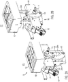
- Fig. 2A shows the lower tool 9 of the sealing station 4 in an isolated manner being located in an open position P1.
- the lower tool 9 may receive trays 3 for the sealing process onto a supporting disc device 14, which is positioned inside a tray reception mold 13.
- Fig. 2A shows that the lifting system 10 provides a drive unit 15, which is used for moving the lower tool 9 from the first position P1 into a second position P2, shown in Fig. 2B .
- the drive unit 15 is a servomotor that is mounted at a lateral side of a stationary basis 16. The latter can be mounted at the machine frame 7 shown in Fig. 1 or being formed as an integrally part thereof.
- the drive unit 15 comprises a rotatable drive shaft 17, which is supported through the stationary basis 16 horizontally.
- the rotationally mounted drive shafts 17 is connected on both lateral sides of the stationary basis 16 with a crank mechanism 18, which is configured for lifting a cross base 19 upwards and downwards below the cross base 19.
- the cross base 19 carries two lifting shafts 20a, 20b at their lower ends. At their upper ends, the lifting shafts 20a, 20b are mounted at a bottom of the tray reception mold 13 as illustrated in Fig. 2B .
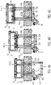
- FIG. 3A The sectional view of Fig. 3A illustrates that the lifting system 10 provides spring units 21a, 21b for mounting the supporting disc device 14 at the stationary basis 16.
- the spring units 21a, 21b are shown in Fig. 3A in an unloaded condition, as the supporting disc device 14 is located in a first position L1 in which the trays 3 are placed thereon.
- Fig. 3B shows the spring units 21a, 21b in a loaded condition wherein the supporting disc device 14 is shifted into a second position L2. In the second position L2, the supporting disc device 14 is located at a higher level compared to the supporting disc device 14 being located in the first position L1.
- Figs. 4A to 4C show a lifting stroke of the lower tool 9 between the open position P1 and the closed position P2. Between the open position P1 and the closed position P2 of the lifting stroke, an intermediate position PI is shown by Fig. 4B . In the intermediate position PI, the supporting disc device 14 is still located in the first position L1, wherein the supporting disc device 14 is now in contact with a bottom 22 of the tray reception mold 13.
- the tray reception mold 13 and the supporting disc device 14 move together upwards into the arrangement as shown by Fig. 4C .
- the lower tool 9 is located in the closed position P2 and the supporting disc device 14 is located in the second position L2, thus being positioned higher as compared to the first position L1 shown by Fig. 4A and Fig. 4B .
- Figs. 4A to 4C also show that the supporting disc device 14 comprises guiding shafts 23a, 23b, which are located between the lifting shafts 20a, 20b.
- Fig. 4B shows that the guiding shafts 23a, 23b reach the cross base 19, potentially docking thereat, thus enabling a robust guiding assembly that moves the supporting disc device 14 from the first position L1 as shown in Fig. 4B , into the second position L2 as shown in Fig. 4C .
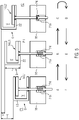
- Fig. 5 shows schematically method steps for lifting the lower tool 9 from the open position P1 via the intermediate position PI into the closed position P2.
- Step A upward movement begins.
- Step B that the tray reception mold 13 contacts the supporting disc device 14 and at this point, the supporting disc device 14 begins to be pushed upwards. Thereby, the supporting disc device 14 is moved from the first position L1, shown in connection method step B, into the higher second position L2, shown in the method step C. Moving the supporting disc device 14 between the steps B and C results in the spring unit 21a being loaded.
- Method step C shows the tray reception mold 13 at a top point of a total stroke H, which comprises 200 millimeters according to Fig. 5 .
- the lower tool 9 is now in the closed position P2 while the supporting disc device 14 being moved into the second higher position L2.
- a spring 23 of the spring unit 21a maximally acts and therefore, the supporting disc device 14 is maximally pressed against the bottom 22 of the tray reception mold 13, thus ensuring a hermetically closed volume V.
- step D the trays 3 are sealed and the overall system begins downward movement.
- the supporting disc device 14 goes down due to gravity and the spring force, which help to increase its descent acceleration and thus, avoid impacting the tray reception mold 13.
- step E the supporting disc device 14 arrives in its initial first position L1.
- step F the whole lifting system 10 returns to the initial position, thus placing the lower tool 9 in the open position P1 again.
Landscapes
- Engineering & Computer Science (AREA)
- Mechanical Engineering (AREA)
- Manufacturing & Machinery (AREA)
- Chemical & Material Sciences (AREA)
- Dispersion Chemistry (AREA)
- Closing Of Containers (AREA)
Abstract
Description
- The present invention refers to a sealing station with a lifting system according to claim 1. In addition, the present invention refers to a method for moving a lower tool of a sealing station between an open position and a closed position according to
claim 13. -
EP 2 179 927 A2 discloses a tray sealer with a sealing station comprising a lower tool, which can be moved between an open position and a closed position by a lifting system. Inside the lower tool a supporting disc device is mounted which moves between a first position, where trays can be placed onto the supporting disc device while the lower tool is in the open position, and a second position, in which the supporting disc device is lowered compared to the first position. In the second position, the supporting disc device is away from the bottoms of the trays when the lower tool is in the closed position for the sealing process. - For moving the known lower tool between the open position and the closed position as well as the known supporting disc device between the first position and the second position, the lower tool of the sealing station has to be designed with a huge capacity height. Thus, the overall volume of the lower tool rises and therefore an evacuation time rises for evacuating the sealing tool in order to produce a predetermined atmosphere rises as well. This, however, makes the tray sealer less competitive. Furthermore, due to the relatively huge size of the lower tool manufacturing costs are likely to increase.
- Other known tray sealers provide a lower tool for the sealing station with a static supporting disc device. The lower tool, when it moves into the closed position, receives the trays at their outer flanges and lifts them up, i.e. away from such static supporting disc device in order to bring them into a sealing position. However, in this case too, especially when the trays have a big height, the lower tool, especially the thereat foreseen tray reception mold, has to be designed with a great height, thus having a relatively huge volume capacity. Consequently, even here the above-mentioned disadvantages occur.
- In view of the above discussed disadvantages in connection with the prior art, it is the object of the present invention to provide a sealing station, which enables operating in shorter process cycles, such as vacuuming the therein disposed trays, and therefore becoming more competitive with respect to known technical approaches. Also, a method for enabling such object should be provided.
- The above-mentioned object can be solved by a sealing station according to claim 1. In addition, the above object can be solved by a method according to
claim 13. - The technical features of the dependent claims provide improved embodiments of the present invention.
- The present invention refers to a sealing station for a packaging machine. The packaging machine can be a tray sealer. The inventive sealing station comprises a lifting system and a lower tool that can be lifted by the lifting system between an open position and a closed position. The lower tool comprising a tray reception mold and a supporting disc device for positioning the trays, wherein the supporting disc device can be moved between a first position in which the trays are placed thereon and a second position in which the supporting disc device is positioned for a sealing process.
- According to the present invention, by being located in the second position, the supporting disc device is located at a higher level compared to the supporting disc device being located in the first position.
- Therefore, in contrast to the known practice, the inventive supporting disc device moves from the first position, which it has initially for receiving trays, upwards into the second position in that the trays can be positioned for the sealing process.
- By moving the supporting disc device from the first position into the second, higher level position, it is possible to design the tray reception mold of the lower tool with a smaller capacity height. As a result, this allows a design having a smaller capacity volume, thus shorter process cycles, such as vacuuming the trays before the sealing process. In other words, by moving the supporting disc device from the first position into the second position in a direction that correlates with the movement of the tray reception mold for moving the trays upwards into the sealing position, it is possible to design the lower tool of the sealing station in a compact manner. Consequently, enabling the positive effect of shorter process times. In addition, manufacturing costs for the lower tool of the sealing station can be reduced.
- Preferably, the supporting disc device can be lifted together with the tray reception mold in a common direction along a predetermined section of a lifting stroke. Here, the supporting disc device becomes a lift by the tray reception mold that is moving into the sealing position. Typically, based on the common upwards movement that is conducted by the supporting disc device and the tray reception mold, the height of the tray reception mold can be reduced.
- One preferred embodiment provides that the supporting disc device is at least partially accommodated within a capacity volume formed by the tray reception mold, said capacity volume comprises a capacity height being smaller than a total lifting stroke of the lower tool by moving between the open position and the closed position.
- It is conceivable that the total lifting stroke measures about 200 millimeters, wherein the capacity height of the tray reception mold measures about 140 millimeters so that there would be an interference of about 60 millimeters, which defines the lifting section along which the supporting disc device is lifted by the tray reception mold.
- A practical, low cost and easy to build variant provides that the lower tool comprises at least one spring unit for mounting the supporting disc device. Preferably, the spring unit is held at the lower tool in an unloaded state when the supporting disc device being in the first position and the spring unit is held in a loaded state when the supporting disc device being located in the second position, respectively.
- Preferably, the spring unit comprises at least one spring with a predetermined spring stroke of about 50 millimeters to 70 millimeters. At the lower tool, the spring's stroke defines the operable movement of the supporting disc device between the first position and the second position.
- According to an improved embodiment, in the closed position of the lower tool, the spring unit presses the supporting disc device with a maximal spring force against a bottom of the tray reception mold. Thereby, a joint between them is maximally sealed and therefore improving the formation of a closed vacuum chamber, thus making that the vacuum cycle highly efficient.
- Preferably, the lifting system comprises a stationary basis and a thereat mounted drive unit for the lower tool, wherein the supporting disc device when being located in the second position is more distanced from the stationary basis compared to the supporting disc device being located in the first position. The stationary basis provides a solid platform for carrying the drive unit as well as supporting the complete lower tool of the sealing station.
- The stationary basis may comprise a beam that is formed for mounting at the machine frame. It would be conceivable that the stationary basis comprises two beams that are built together. Ideally, the stationary basis carries the spring unit in an integral manner, such that the spring unit is completely accommodated within a constructed size of the stationary basis. Thereby, the compact, integrated design of the lifting station is improved.
- It is conceivable that the drive unit is used for moving sectionwise both, the tray reception mold coupled with the supporting disc device. Here, by actuating the drive unit, the tray reception mold is moved upwards and downwards, wherein by the upward movement, the tray reception mold may contact with the supporting disc device and lift it by continuing the upward movement from its first position into its second, higher level position. Accordingly, the drive unit initially lifts the tray reception mold towards the supporting disc device waiting in the first position, wherein once the tray reception mold is docked at the supporting disc device; both are lifted upwards by the drive unit until the tray reception mold reaches the closed position for the sealing process. Once the sealing process is completed, the drive unit lowers the tray reception mold, while the supporting disc device sitting thereon is concurrently lowered from its second position into the first position. When the supporting disc device arrives the first initial position, the supporting disc device is left there behind while the drive unit continues to lower the tray reception mold into the open position.
- It is a preferred variant that the drive unit is a servomotor that is fixed at a lateral side of the stationary basis. The servomotor enables a very precise lifting and lowering movement of the lower tool and can be mounted in a compact manner at the sealing station.
- Preferably, the lifting system comprises a lifting mechanism with at least two vertically slidable lifting shafts. The lifting mechanism preferably comprises a crank mechanism that connects the drive unit with the vertically slidable lifting shafts. The crank mechanism can be built on two lateral sides of the stationary basis.
- A purposeful embodiment provides that the lifting shafts are mounted onto a height adjustable cross base with their lower ends. The height adjustable cross base can be formed as a plate and therefore provides a robust carrier for the lower ends of the lifting shafts. Also, movement of the cross base can be actuated by the drive unit via the crank mechanism. For a compact design, the height adjustable cross base can be positioned below the stationary basis.
- One variant provides that the supporting disc device comprises at least two guiding shafts, which seen in a vertical projection plane, are mounted between the lifting shafts. This improves a precise guiding of the supporting disc device during the lifting stroke of the lower tool.
- It is conceivable that the guide shafts can dock with their lower ends at a side of the cross base facing the lower ends. Such docking can occur at that time when the tray reception mold reaches into contact with the supporting disc device for lifting the latter from its first position into the second, higher level position. By such at least time wise connection between the lower ends of the guide shafts and the cross base, guiding of the supporting disc device in a long-term precise manner can be better guaranteed.
- The present invention further refers to a method for moving a lower tool of a sealing station between an open position and a closed position, wherein in the open position of the lower tool, trays are placed on a supporting disc device of the lower tool, and wherein, in the closed position of the lower tool, the trays are sealed.
- According to the inventive method, the supporting disc device is moved for the sealing process from a first position in which the trays are positioned on the supporting disc device into a second, higher level position as compared to the first position. Said movement of the supporting disc device enables a reduced-height design for the lower tool, especially a tray reception mold of the lower tool, and therefore, provides the possibility of shorter process cycles, e.g. a shorter vacuum cycle before sealing. Because the overall volume capacity of the lower tool can be reduced, there is the possibility of reducing manufacturing costs of the lower tool, too. Thus, rendering the sealing station used for the inventive method more competitive.
- Preferably, the supporting disc device is lifted with a height-adjustable tray reception mold that comes into contact from below with the supporting disc device thus moving it form the first position into the second position. Therefore, during the movement between the first position and the second position, the tray reception mold and the thereby lifted supporting disc device contact and move together in the same direction along a common section of the lifting stroke. The length of such section provides the potential of reducing the construction height of the lower tool.
- A beneficial embodiment provides that the supporting disc device is lifted against a spring force of a spring unit from the first position to the second position. Especially, being located in the second position, the spring unit may act with a maximum spring force that presses the supporting disc device against a bottom of the tray reception mold, thus establishing a sufficient sealing for forming the vacuum chamber for the vacuum process.
- Advantageous embodiments of the invention are explained in more detail by means of the following drawings:
- Fig. 1
- shows a perspective view of a tray sealer,
- Fig. 2A
- shows a lower tool of a sealing station in an open position,
- Fig. 2B
- shows the lower tool of
Fig. 2A in a closed position, - Fig. 3A
- shows a sectional view of
Fig. 2A , - Fig. 3B
- shows a sectional view of
Fig. 2A , - Figs. 4A-4C
- show a total lifting stroke of the lower tool, and
- Fig. 5
- shows schematically a method for lifting and lowering a lower tool between an open and closed position.
- Identical components are consistently marked with identical reference numerals in the figures.
-
Fig. 1 shows a tray sealer 1 comprising a first conveyer 2 for providing unsealed trays 3, a sealing station 4 for sealing the trays 3 with alid foil 5, and further comprising a second conveyer 6 for moving the sealed trays 3 away from the sealing station 4 for further handling. The first conveyer 2, the sealing station 4, and the second conveyer 6 are arranged along a transport direction R and are mounted onto a machine frame 7 of the tray sealer 1. - The trays 3 which are provided onto the first conveyer 2 can be picked up by a
gripper 8 and can be transported into the sealing station 4 for a sealing process. In the sealing station 4, the trays 3 are received in alower tool 9, which can be lifted vertically upwards by alifting system 10 towards anupper tool 11 of the sealing station 4, thereby, forming a closed sealing chamber for a vacuum process and/or a gassing process as well as sealing with thelid foil 5.Fig. 1 further shows that the tray sealer 1 provides auser control interface 12 for controlling the packaging process and observing the same. -
Fig. 2A shows thelower tool 9 of the sealing station 4 in an isolated manner being located in an open position P1. In the open position P1, thelower tool 9 may receive trays 3 for the sealing process onto a supportingdisc device 14, which is positioned inside atray reception mold 13. - Further,
Fig. 2A shows that thelifting system 10 provides adrive unit 15, which is used for moving thelower tool 9 from the first position P1 into a second position P2, shown inFig. 2B . Thedrive unit 15 is a servomotor that is mounted at a lateral side of astationary basis 16. The latter can be mounted at the machine frame 7 shown inFig. 1 or being formed as an integrally part thereof. - As shown by
Fig. 2A thedrive unit 15 comprises arotatable drive shaft 17, which is supported through thestationary basis 16 horizontally. The rotationally mounteddrive shafts 17 is connected on both lateral sides of thestationary basis 16 with acrank mechanism 18, which is configured for lifting across base 19 upwards and downwards below thecross base 19. Thecross base 19 carries twolifting shafts lifting shafts tray reception mold 13 as illustrated inFig. 2B . - In
Fig. 2A , by actuating thedrive unit 15, thedrive shaft 17 rotates thecrank mechanism 18 thereby lifting the thereat mountedcross base 19 and the thereon mounted liftingshafts tray reception mold 13 is moved from the open position P1 into the closed position P2 illustrated inFig. 2B . - The sectional view of
Fig. 3A illustrates that thelifting system 10 providesspring units disc device 14 at thestationary basis 16. Thespring units Fig. 3A in an unloaded condition, as the supportingdisc device 14 is located in a first position L1 in which the trays 3 are placed thereon. -
Fig. 3B shows thespring units disc device 14 is shifted into a second position L2. In the second position L2, the supportingdisc device 14 is located at a higher level compared to the supportingdisc device 14 being located in the first position L1. -
Figs. 4A to 4C show a lifting stroke of thelower tool 9 between the open position P1 and the closed position P2. Between the open position P1 and the closed position P2 of the lifting stroke, an intermediate position PI is shown byFig. 4B . In the intermediate position PI, the supportingdisc device 14 is still located in the first position L1, wherein the supportingdisc device 14 is now in contact with a bottom 22 of thetray reception mold 13. - From the intermediate position PI, the
tray reception mold 13 and the supportingdisc device 14 move together upwards into the arrangement as shown byFig. 4C . InFig. 4C , thelower tool 9 is located in the closed position P2 and the supportingdisc device 14 is located in the second position L2, thus being positioned higher as compared to the first position L1 shown byFig. 4A and Fig. 4B . -
Figs. 4A to 4C also show that the supportingdisc device 14 comprises guidingshafts shafts Fig. 4B shows that the guidingshafts cross base 19, potentially docking thereat, thus enabling a robust guiding assembly that moves the supportingdisc device 14 from the first position L1 as shown inFig. 4B , into the second position L2 as shown inFig. 4C . -
Fig. 5 shows schematically method steps for lifting thelower tool 9 from the open position P1 via the intermediate position PI into the closed position P2. - In Step A upward movement begins.
- In Step B that the
tray reception mold 13 contacts the supportingdisc device 14 and at this point, the supportingdisc device 14 begins to be pushed upwards. Thereby, the supportingdisc device 14 is moved from the first position L1, shown in connection method step B, into the higher second position L2, shown in the method step C. Moving the supportingdisc device 14 between the steps B and C results in thespring unit 21a being loaded. - Method step C shows the
tray reception mold 13 at a top point of a total stroke H, which comprises 200 millimeters according toFig. 5 . Thelower tool 9 is now in the closed position P2 while the supportingdisc device 14 being moved into the second higher position L2. Thus, lifting the trays 3 that are held inside thetray reception mold 13 for a sealing process. At this stage, a spring 23 of thespring unit 21a maximally acts and therefore, the supportingdisc device 14 is maximally pressed against the bottom 22 of thetray reception mold 13, thus ensuring a hermetically closed volume V. - In step D, the trays 3 are sealed and the overall system begins downward movement. The supporting
disc device 14 goes down due to gravity and the spring force, which help to increase its descent acceleration and thus, avoid impacting thetray reception mold 13. - In step E, the supporting
disc device 14 arrives in its initial first position L1. - In step F, the
whole lifting system 10 returns to the initial position, thus placing thelower tool 9 in the open position P1 again.
Claims (15)
- Sealing station (4) for a packaging machine, wherein the sealing station (4) comprises a lifting system (10) and a lower tool (9) that can be lifted by the lifting system (10) between an open position (P1) and a closed position (P2), the lower tool (9) comprising a tray reception mold (13) and a supporting disc device (14) for positioning trays (3), wherein the supporting device (14) can be moved between a first position (L1) in which the trays (3) are placed thereon, and a second position (L2) in which the supporting disc device (14) is positioned for a sealing process, characterized in that when located in the second position (L2), the supporting disc device (14) is located at a higher level compared to the supporting disc device (14) being located in the first position (L1).
- Sealing station according to claim 1, characterized in that the supporting disc device (14) is liftable together with the tray reception mold (13) in a common direction along a pre-determined section (T) of a lifting stoke (H).
- Sealing station according to claim 1 or claim 2, characterized in that the supporting disc device (14) is at least partially accommodated within a capacity volume (V) formed by the tray reception mold (13), said capacity volume (V) comprises a capacity height (h) being smaller than a total lifting stroke (H) of the lower tool (9) by moving between the open position (P1) and the closed position (P2).
- Sealing station according to one of the previous claims, characterized in that the listing system (10) comprises at least one spring unit (21a, 21b) for mounting the supporting disc device (14).
- Sealing station according to claim 4, characterized in that the spring unit (21a, 21b) comprises at least one spring (24) with a spring stroke of about 50 millimeters to 70 millimeters.
- Sealing station according to claim 4 or claim 5, characterized in that in the closed position (P2) of the lower tool (9) the spring unit (21a, 21b) is configured to press the supporting disc device (14) with a maximal spring force against a bottom (22) of the tray reception mold (13).
- Sealing station according to one of the previous claims, characterized in that the lifting system (10) comprises a stationary basis (16) and a thereat mounted drive unit (15) for the lower tool (9), wherein the supporting disc device (14) being located in the second position (L2) is more distanced from the stationary basis (16) compared to the supporting disc device (14) being located in the first position (L1).
- Sealing station according to claim 7, characterized in that the drive unit (15) is used for moving the tray reception mold (13) and the supporting disc device (14).
- Sealing station according to one of the previous claims, characterized in that the lifting system (10) comprises a lifting mechanism with at least two vertically slidable lifting shafts (20a, 20b).
- Sealing station according to claim 9, characterized in that the lifting shafts (20a, 20b) are mounted onto a height-adjustable cross base (19) with their lower ends.
- Sealing station according to claim 9 or claim 10, characterized in that the supporting disc device (14) comprises at least two guiding shafts (23a, 23b), which, seen in a vertical projection plane, are mounted between the lifting shafts (20a, 20b).
- Sealing station according to claim 11, characterized in that the guide shafts (23a, 23b) can dock with their lower ends at a side of the cross base (19) facing the lower ends.
- Method for moving a lower tool (9) of a sealing station (4) between an open position (P1) and a closed position (P2), wherein, in the open position (P1) of the lower tool (9), trays (3) are placed on a supporting disc device (14) of the lower tool (9) and wherein, in the closed position (P2) of the lower tool (9), the trays (3) are sealed, characterized in that the supporting disc device (14) is moved for the sealing process from a first position (L1) in which the trays (3) are positioned on the supporting disc device (14) into a second, higher level position (L2) as compared to the first position (L1).
- Method according to claim 13, characterized in that the supporting disc device (14) is lifted with a height-adjustable tray reception mold (13) that comes into contact with the supporting disc device (14) from the first position (L1) into the second position (L2).
- Method according to claim 13 or claim 14, characterized in that the supporting disc device (14) is moved against a spring force of a spring unit (21a, 21b) from the first position (L1) into the second position (L2).
Priority Applications (2)
| Application Number | Priority Date | Filing Date | Title |
|---|---|---|---|
| ES21382153T ES3062535T3 (en) | 2021-02-24 | 2021-02-24 | Sealing station with lifting system |
| EP21382153.1A EP4049937B1 (en) | 2021-02-24 | 2021-02-24 | Sealing station with lifting system |
Applications Claiming Priority (1)
| Application Number | Priority Date | Filing Date | Title |
|---|---|---|---|
| EP21382153.1A EP4049937B1 (en) | 2021-02-24 | 2021-02-24 | Sealing station with lifting system |
Publications (2)
| Publication Number | Publication Date |
|---|---|
| EP4049937A1 true EP4049937A1 (en) | 2022-08-31 |
| EP4049937B1 EP4049937B1 (en) | 2026-01-28 |
Family
ID=75277948
Family Applications (1)
| Application Number | Title | Priority Date | Filing Date |
|---|---|---|---|
| EP21382153.1A Active EP4049937B1 (en) | 2021-02-24 | 2021-02-24 | Sealing station with lifting system |
Country Status (2)
| Country | Link |
|---|---|
| EP (1) | EP4049937B1 (en) |
| ES (1) | ES3062535T3 (en) |
Citations (8)
| Publication number | Priority date | Publication date | Assignee | Title |
|---|---|---|---|---|
| NL9202176A (en) * | 1992-08-04 | 1994-03-01 | Stork Titan Bv | Foodstuff packaging |
| US20060048480A1 (en) * | 2004-09-07 | 2006-03-09 | Ibaraki Seiki Machinery Company, Ltd. | Sealing and packaging device for cover film on tray |
| EP2179927A2 (en) | 2008-10-21 | 2010-04-28 | Multivac Sepp Haggenmüller GmbH & Co. KG | Seal system for packaging machine tools with integrated lifting rod |
| US20120204516A1 (en) * | 2009-07-29 | 2012-08-16 | Cryovac, Inc. | Vacuum Skin Packaging of a Product Arranged on a Support |
| EP3130546A1 (en) * | 2015-08-11 | 2017-02-15 | MULTIVAC Sepp Haggenmüller SE & Co. KG | Pull crank lifter for packaging machine |
| WO2018193383A1 (en) * | 2017-04-19 | 2018-10-25 | Cryovac, Inc. | Tray sealer and operating method |
| EP3235741B1 (en) * | 2016-04-22 | 2020-01-29 | Mauro Scolaro | Device for packaging trays |
| EP3715267A1 (en) * | 2019-03-26 | 2020-09-30 | Weber Maschinenbau GmbH Breidenbach | Work station for a packing machine |
-
2021
- 2021-02-24 EP EP21382153.1A patent/EP4049937B1/en active Active
- 2021-02-24 ES ES21382153T patent/ES3062535T3/en active Active
Patent Citations (8)
| Publication number | Priority date | Publication date | Assignee | Title |
|---|---|---|---|---|
| NL9202176A (en) * | 1992-08-04 | 1994-03-01 | Stork Titan Bv | Foodstuff packaging |
| US20060048480A1 (en) * | 2004-09-07 | 2006-03-09 | Ibaraki Seiki Machinery Company, Ltd. | Sealing and packaging device for cover film on tray |
| EP2179927A2 (en) | 2008-10-21 | 2010-04-28 | Multivac Sepp Haggenmüller GmbH & Co. KG | Seal system for packaging machine tools with integrated lifting rod |
| US20120204516A1 (en) * | 2009-07-29 | 2012-08-16 | Cryovac, Inc. | Vacuum Skin Packaging of a Product Arranged on a Support |
| EP3130546A1 (en) * | 2015-08-11 | 2017-02-15 | MULTIVAC Sepp Haggenmüller SE & Co. KG | Pull crank lifter for packaging machine |
| EP3235741B1 (en) * | 2016-04-22 | 2020-01-29 | Mauro Scolaro | Device for packaging trays |
| WO2018193383A1 (en) * | 2017-04-19 | 2018-10-25 | Cryovac, Inc. | Tray sealer and operating method |
| EP3715267A1 (en) * | 2019-03-26 | 2020-09-30 | Weber Maschinenbau GmbH Breidenbach | Work station for a packing machine |
Also Published As
| Publication number | Publication date |
|---|---|
| ES3062535T3 (en) | 2026-04-13 |
| EP4049937B1 (en) | 2026-01-28 |
Similar Documents
| Publication | Publication Date | Title |
|---|---|---|
| CN112678214B (en) | A linear filling and capping machine | |
| JPH11105835A (en) | Lifting device and packaging machine | |
| CN111846468B (en) | Tray sealing machine and method for gently picking up tray | |
| CN108033267A (en) | Sheet metal carrying process | |
| KR20130093533A (en) | Deaeration, sealing method and sealing device for bag | |
| EP4049937B1 (en) | Sealing station with lifting system | |
| US12122549B2 (en) | Apparatus and method for inserting and unloading stacked gloves into a packing box | |
| KR101107575B1 (en) | Vacuum evaporation apparatus for changing crucibles without breaking the vacuum in the vacuum chamber | |
| CN214524865U (en) | Automatic closing device suitable for multiple specification bag type | |
| CN110371353B (en) | Packaging machine | |
| CN118571630A (en) | Inductor preparation device and inductor preparation process | |
| CN217193476U (en) | A cover feeding device | |
| CN211076479U (en) | Packaging machine | |
| CN110436207B (en) | Automatic lifting conveyor device | |
| JPS6341320A (en) | Boxing bowl taking out device | |
| CN217374976U (en) | Horizontal filling vertical prefabricated bag packaging equipment | |
| CN224076303U (en) | Vacuum chamber device for forming easy-open cover | |
| JP2021187597A (en) | Step disassembling device | |
| CN217706522U (en) | Box falling removing device | |
| CN216177956U (en) | Equipment for mounting lifting handle and earshell on packaging can cover | |
| CN223086402U (en) | Ice cream filling and packaging machine | |
| CN223013870U (en) | Blister unloading mechanism and blister folding machine | |
| KR102834446B1 (en) | Manufacturing machine for sealed container product | |
| CN212765268U (en) | Double-table vacuum printing device | |
| CN223721277U (en) | Feeding and dishing device for flexible vacuum packaging ceramic balls |
Legal Events
| Date | Code | Title | Description |
|---|---|---|---|
| PUAI | Public reference made under article 153(3) epc to a published international application that has entered the european phase |
Free format text: ORIGINAL CODE: 0009012 |
|
| STAA | Information on the status of an ep patent application or granted ep patent |
Free format text: STATUS: THE APPLICATION HAS BEEN PUBLISHED |
|
| AK | Designated contracting states |
Kind code of ref document: A1 Designated state(s): AL AT BE BG CH CY CZ DE DK EE ES FI FR GB GR HR HU IE IS IT LI LT LU LV MC MK MT NL NO PL PT RO RS SE SI SK SM TR |
|
| STAA | Information on the status of an ep patent application or granted ep patent |
Free format text: STATUS: REQUEST FOR EXAMINATION WAS MADE |
|
| 17P | Request for examination filed |
Effective date: 20230216 |
|
| RBV | Designated contracting states (corrected) |
Designated state(s): AL AT BE BG CH CY CZ DE DK EE ES FI FR GB GR HR HU IE IS IT LI LT LU LV MC MK MT NL NO PL PT RO RS SE SI SK SM TR |
|
| P01 | Opt-out of the competence of the unified patent court (upc) registered |
Effective date: 20230801 |
|
| GRAP | Despatch of communication of intention to grant a patent |
Free format text: ORIGINAL CODE: EPIDOSNIGR1 |
|
| STAA | Information on the status of an ep patent application or granted ep patent |
Free format text: STATUS: GRANT OF PATENT IS INTENDED |
|
| RIC1 | Information provided on ipc code assigned before grant |
Ipc: B65B 51/14 20060101AFI20250827BHEP Ipc: B65B 7/16 20060101ALI20250827BHEP Ipc: B65B 65/02 20060101ALI20250827BHEP Ipc: B29C 65/00 20060101ALI20250827BHEP Ipc: B65B 31/02 20060101ALI20250827BHEP Ipc: B29C 65/02 20060101ALI20250827BHEP Ipc: B29C 65/78 20060101ALI20250827BHEP |
|
| INTG | Intention to grant announced |
Effective date: 20250905 |
|
| GRAS | Grant fee paid |
Free format text: ORIGINAL CODE: EPIDOSNIGR3 |
|
| GRAA | (expected) grant |
Free format text: ORIGINAL CODE: 0009210 |
|
| STAA | Information on the status of an ep patent application or granted ep patent |
Free format text: STATUS: THE PATENT HAS BEEN GRANTED |
|
| AK | Designated contracting states |
Kind code of ref document: B1 Designated state(s): AL AT BE BG CH CY CZ DE DK EE ES FI FR GB GR HR HU IE IS IT LI LT LU LV MC MK MT NL NO PL PT RO RS SE SI SK SM TR |
|
| REG | Reference to a national code |
Ref country code: CH Ref legal event code: F10 Free format text: ST27 STATUS EVENT CODE: U-0-0-F10-F00 (AS PROVIDED BY THE NATIONAL OFFICE) Effective date: 20260128 Ref country code: GB Ref legal event code: FG4D |
|
| REG | Reference to a national code |
Ref country code: NL Ref legal event code: FP |
|
| REG | Reference to a national code |
Ref country code: DE Ref legal event code: R096 Ref document number: 602021046764 Country of ref document: DE |
|
| REG | Reference to a national code |
Ref country code: IE Ref legal event code: FG4D |
|
| PGFP | Annual fee paid to national office [announced via postgrant information from national office to epo] |
Ref country code: GB Payment date: 20260302 Year of fee payment: 6 |
|
| PGFP | Annual fee paid to national office [announced via postgrant information from national office to epo] |
Ref country code: DE Payment date: 20260302 Year of fee payment: 6 |
|
| REG | Reference to a national code |
Ref country code: ES Ref legal event code: FG2A Ref document number: 3062535 Country of ref document: ES Kind code of ref document: T3 Effective date: 20260413 |
|
| PGFP | Annual fee paid to national office [announced via postgrant information from national office to epo] |
Ref country code: NL Payment date: 20260302 Year of fee payment: 6 |
|
| PGFP | Annual fee paid to national office [announced via postgrant information from national office to epo] |
Ref country code: FR Payment date: 20260302 Year of fee payment: 6 |
|
| REG | Reference to a national code |
Ref country code: AT Ref legal event code: MK05 Ref document number: 1880975 Country of ref document: AT Kind code of ref document: T Effective date: 20260128 |
|
| PG25 | Lapsed in a contracting state [announced via postgrant information from national office to epo] |
Ref country code: RS Free format text: LAPSE BECAUSE OF FAILURE TO SUBMIT A TRANSLATION OF THE DESCRIPTION OR TO PAY THE FEE WITHIN THE PRESCRIBED TIME-LIMIT Effective date: 20260428 |
|
| PGFP | Annual fee paid to national office [announced via postgrant information from national office to epo] |
Ref country code: ES Payment date: 20260417 Year of fee payment: 6 |
|
| PG25 | Lapsed in a contracting state [announced via postgrant information from national office to epo] |
Ref country code: PL Free format text: LAPSE BECAUSE OF FAILURE TO SUBMIT A TRANSLATION OF THE DESCRIPTION OR TO PAY THE FEE WITHIN THE PRESCRIBED TIME-LIMIT Effective date: 20260128 |
|
| PG25 | Lapsed in a contracting state [announced via postgrant information from national office to epo] |
Ref country code: GR Free format text: LAPSE BECAUSE OF FAILURE TO SUBMIT A TRANSLATION OF THE DESCRIPTION OR TO PAY THE FEE WITHIN THE PRESCRIBED TIME-LIMIT Effective date: 20260429 |
|
| PGFP | Annual fee paid to national office [announced via postgrant information from national office to epo] |
Ref country code: IT Payment date: 20260519 Year of fee payment: 6 |
|
| REG | Reference to a national code |
Ref country code: LT Ref legal event code: MG9D |
|
| PG25 | Lapsed in a contracting state [announced via postgrant information from national office to epo] |
Ref country code: LT Free format text: LAPSE BECAUSE OF FAILURE TO SUBMIT A TRANSLATION OF THE DESCRIPTION OR TO PAY THE FEE WITHIN THE PRESCRIBED TIME-LIMIT Effective date: 20260128 |
|
| PG25 | Lapsed in a contracting state [announced via postgrant information from national office to epo] |
Ref country code: NO Free format text: LAPSE BECAUSE OF FAILURE TO SUBMIT A TRANSLATION OF THE DESCRIPTION OR TO PAY THE FEE WITHIN THE PRESCRIBED TIME-LIMIT Effective date: 20260428 |
|
| PG25 | Lapsed in a contracting state [announced via postgrant information from national office to epo] |
Ref country code: FI Free format text: LAPSE BECAUSE OF FAILURE TO SUBMIT A TRANSLATION OF THE DESCRIPTION OR TO PAY THE FEE WITHIN THE PRESCRIBED TIME-LIMIT Effective date: 20260128 Ref country code: AT Free format text: LAPSE BECAUSE OF FAILURE TO SUBMIT A TRANSLATION OF THE DESCRIPTION OR TO PAY THE FEE WITHIN THE PRESCRIBED TIME-LIMIT Effective date: 20260128 Ref country code: SE Free format text: LAPSE BECAUSE OF FAILURE TO SUBMIT A TRANSLATION OF THE DESCRIPTION OR TO PAY THE FEE WITHIN THE PRESCRIBED TIME-LIMIT Effective date: 20260128 |
|
| PG25 | Lapsed in a contracting state [announced via postgrant information from national office to epo] |
Ref country code: HR Free format text: LAPSE BECAUSE OF FAILURE TO SUBMIT A TRANSLATION OF THE DESCRIPTION OR TO PAY THE FEE WITHIN THE PRESCRIBED TIME-LIMIT Effective date: 20260128 |
|
| PG25 | Lapsed in a contracting state [announced via postgrant information from national office to epo] |
Ref country code: IS Free format text: LAPSE BECAUSE OF FAILURE TO SUBMIT A TRANSLATION OF THE DESCRIPTION OR TO PAY THE FEE WITHIN THE PRESCRIBED TIME-LIMIT Effective date: 20260528 Ref country code: PT Free format text: LAPSE BECAUSE OF FAILURE TO SUBMIT A TRANSLATION OF THE DESCRIPTION OR TO PAY THE FEE WITHIN THE PRESCRIBED TIME-LIMIT Effective date: 20260528 |
|
| PG25 | Lapsed in a contracting state [announced via postgrant information from national office to epo] |
Ref country code: LV Free format text: LAPSE BECAUSE OF FAILURE TO SUBMIT A TRANSLATION OF THE DESCRIPTION OR TO PAY THE FEE WITHIN THE PRESCRIBED TIME-LIMIT Effective date: 20260128 |
|
| PG25 | Lapsed in a contracting state [announced via postgrant information from national office to epo] |
Ref country code: BG Free format text: LAPSE BECAUSE OF FAILURE TO SUBMIT A TRANSLATION OF THE DESCRIPTION OR TO PAY THE FEE WITHIN THE PRESCRIBED TIME-LIMIT Effective date: 20260128 |