EP3715267A1 - Work station for a packing machine - Google Patents
Work station for a packing machine Download PDFInfo
- Publication number
- EP3715267A1 EP3715267A1 EP20155990.3A EP20155990A EP3715267A1 EP 3715267 A1 EP3715267 A1 EP 3715267A1 EP 20155990 A EP20155990 A EP 20155990A EP 3715267 A1 EP3715267 A1 EP 3715267A1
- Authority
- EP
- European Patent Office
- Prior art keywords
- rotor
- gear
- working unit
- drive
- work station
- Prior art date
- Legal status (The legal status is an assumption and is not a legal conclusion. Google has not performed a legal analysis and makes no representation as to the accuracy of the status listed.)
- Granted
Links
- 238000012856 packing Methods 0.000 title 1
- 238000004806 packaging method and process Methods 0.000 claims abstract description 69
- 230000007246 mechanism Effects 0.000 claims abstract description 51
- 230000005540 biological transmission Effects 0.000 claims abstract description 34
- 238000007789 sealing Methods 0.000 claims abstract description 23
- 238000004080 punching Methods 0.000 claims abstract description 16
- 238000005520 cutting process Methods 0.000 claims abstract description 14
- 230000008878 coupling Effects 0.000 claims description 59
- 238000010168 coupling process Methods 0.000 claims description 59
- 238000005859 coupling reaction Methods 0.000 claims description 59
- 239000000463 material Substances 0.000 claims description 7
- 230000001360 synchronised effect Effects 0.000 claims description 4
- 238000003856 thermoforming Methods 0.000 claims description 4
- 238000007493 shaping process Methods 0.000 claims description 3
- 238000000926 separation method Methods 0.000 claims description 2
- 238000009434 installation Methods 0.000 description 9
- 238000002372 labelling Methods 0.000 description 5
- 235000013305 food Nutrition 0.000 description 4
- 230000008859 change Effects 0.000 description 3
- 238000000034 method Methods 0.000 description 3
- 230000008569 process Effects 0.000 description 3
- 230000008901 benefit Effects 0.000 description 2
- 230000033228 biological regulation Effects 0.000 description 2
- 230000001419 dependent effect Effects 0.000 description 2
- 238000000465 moulding Methods 0.000 description 2
- 238000011144 upstream manufacturing Methods 0.000 description 2
- 230000004308 accommodation Effects 0.000 description 1
- 230000003213 activating effect Effects 0.000 description 1
- 238000003491 array Methods 0.000 description 1
- 230000000712 assembly Effects 0.000 description 1
- 238000000429 assembly Methods 0.000 description 1
- 239000000969 carrier Substances 0.000 description 1
- 235000013351 cheese Nutrition 0.000 description 1
- 238000010276 construction Methods 0.000 description 1
- 230000002996 emotional effect Effects 0.000 description 1
- 238000005259 measurement Methods 0.000 description 1
- 235000013372 meat Nutrition 0.000 description 1
- 238000009740 moulding (composite fabrication) Methods 0.000 description 1
- 235000013580 sausages Nutrition 0.000 description 1
- 230000006641 stabilisation Effects 0.000 description 1
- 238000011105 stabilization Methods 0.000 description 1
Images


Classifications
-
- B—PERFORMING OPERATIONS; TRANSPORTING
- B65—CONVEYING; PACKING; STORING; HANDLING THIN OR FILAMENTARY MATERIAL
- B65B—MACHINES, APPARATUS OR DEVICES FOR, OR METHODS OF, PACKAGING ARTICLES OR MATERIALS; UNPACKING
- B65B9/00—Enclosing successive articles, or quantities of material, e.g. liquids or semiliquids, in flat, folded, or tubular webs of flexible sheet material; Subdividing filled flexible tubes to form packages
- B65B9/02—Enclosing successive articles, or quantities of material between opposed webs
- B65B9/04—Enclosing successive articles, or quantities of material between opposed webs one or both webs being formed with pockets for the reception of the articles, or of the quantities of material
-
- B—PERFORMING OPERATIONS; TRANSPORTING
- B26—HAND CUTTING TOOLS; CUTTING; SEVERING
- B26D—CUTTING; DETAILS COMMON TO MACHINES FOR PERFORATING, PUNCHING, CUTTING-OUT, STAMPING-OUT OR SEVERING
- B26D5/00—Arrangements for operating and controlling machines or devices for cutting, cutting-out, stamping-out, punching, perforating, or severing by means other than cutting
- B26D5/08—Means for actuating the cutting member to effect the cut
- B26D5/14—Crank and pin means
-
- B—PERFORMING OPERATIONS; TRANSPORTING
- B26—HAND CUTTING TOOLS; CUTTING; SEVERING
- B26F—PERFORATING; PUNCHING; CUTTING-OUT; STAMPING-OUT; SEVERING BY MEANS OTHER THAN CUTTING
- B26F1/00—Perforating; Punching; Cutting-out; Stamping-out; Apparatus therefor
-
- B—PERFORMING OPERATIONS; TRANSPORTING
- B65—CONVEYING; PACKING; STORING; HANDLING THIN OR FILAMENTARY MATERIAL
- B65B—MACHINES, APPARATUS OR DEVICES FOR, OR METHODS OF, PACKAGING ARTICLES OR MATERIALS; UNPACKING
- B65B65/00—Details peculiar to packaging machines and not otherwise provided for; Arrangements of such details
- B65B65/02—Driving gear
-
- B—PERFORMING OPERATIONS; TRANSPORTING
- B29—WORKING OF PLASTICS; WORKING OF SUBSTANCES IN A PLASTIC STATE IN GENERAL
- B29C—SHAPING OR JOINING OF PLASTICS; SHAPING OF MATERIAL IN A PLASTIC STATE, NOT OTHERWISE PROVIDED FOR; AFTER-TREATMENT OF THE SHAPED PRODUCTS, e.g. REPAIRING
- B29C51/00—Shaping by thermoforming, i.e. shaping sheets or sheet like preforms after heating, e.g. shaping sheets in matched moulds or by deep-drawing; Apparatus therefor
- B29C51/18—Thermoforming apparatus
-
- B—PERFORMING OPERATIONS; TRANSPORTING
- B29—WORKING OF PLASTICS; WORKING OF SUBSTANCES IN A PLASTIC STATE IN GENERAL
- B29C—SHAPING OR JOINING OF PLASTICS; SHAPING OF MATERIAL IN A PLASTIC STATE, NOT OTHERWISE PROVIDED FOR; AFTER-TREATMENT OF THE SHAPED PRODUCTS, e.g. REPAIRING
- B29C51/00—Shaping by thermoforming, i.e. shaping sheets or sheet like preforms after heating, e.g. shaping sheets in matched moulds or by deep-drawing; Apparatus therefor
- B29C51/26—Component parts, details or accessories; Auxiliary operations
- B29C51/30—Moulds
- B29C51/38—Opening, closing or clamping means
Definitions
- the invention relates to a work station for a packaging machine, with a frame supported on the floor, at least one working unit with a work tool, and at least one lifting mechanism supported on the frame, with which the working unit can be raised and lowered relative to the frame for performing a working stroke.
- the packaging machine is in particular a thermoforming packaging machine.
- Packaging machines with which packaging is produced, in particular from material webs such as film webs, and at the same time filled with products to be packaged, such as food, perform a multitude of work steps at several different work stations, which are distributed in a transport or longitudinal direction of the packaging machine are.
- depressions also known as depressions are formed in a lower film.
- an upper film previously applied to the lower film is bonded to the lower film, which is typically done by a thermal process known as sealing.
- the packs are separated at work stations located downstream of the sealing station. This is done in particular by cutting or punching tools. Further work stations, which are arranged in particular upstream of the sealing station, can serve to include the lower film and / or the upper film and any intermediate films provided To provide perforations, which are used, for example, in the sealing station for evacuating and gassing the packaging.
- the work stations of a packaging machine typically include at least one work tool, which is raised to perform a work step in order to interact with a counter-tool.
- the counter-tool can be a simple abutment or a tool that performs an additional work function.
- the counter-tool can also perform a lifting movement to carry out a work step.
- the respective working width of the packaging machine i.e. its dimension measured transversely to the transport direction of the material webs and thus transversely to the working or longitudinal direction of the packaging machine, provides a corresponding installation space for the workstations
- the installation space available in the transport or longitudinal direction is for the The lifting mechanism of the workstation is regularly very limited.
- the object of the invention is to develop a workstation of the type mentioned at the outset in such a way that, with as little space as possible, especially in The longitudinal direction of the working stroke of the working unit can be controlled as flexibly as possible, while at the same time it must be ensured that there is sufficient stability in order to be able to transmit the greatest possible forces.
- the lifting mechanism comprises a drive, a rotor and a gear, the rotor being rotatable by means of the drive for lifting the working unit in one direction and for lowering the working unit in the opposite direction, the gearing on the input side with the Rotor and is connected on the output side to the working unit, and wherein the drive is a rotary drive with a rotating drive element, in particular a rotor or an output shaft of an electric motor, the rotary movement of the output element being transmitted to the rotor.
- the drive concept according to the invention in which a rotary drive sets a rotor in rotation, the rotational movement of which is transmitted to the gearbox, in which linear drives are consequently avoided, allows different gearbox concepts that can be adapted to the respective requirements, but which in any case save space and in one can be designed to transmit large forces in a sufficiently stable manner.
- the drive comprises a servomotor.
- a servomotor allows a flexibly controlled movement of the lifting mechanism and thus of the working unit.
- the speed of the working unit during the working stroke can be varied as required.
- Dependent on a fundamentally arbitrary speed profile can thus be specified for the working unit for the respective application.
- the lifting mechanism preferably extends in a transverse direction and in a longitudinal direction, the extent of the lifting mechanism in the longitudinal direction being smaller than in the transverse direction.
- the extension in the longitudinal direction is less than 1/2 or less than 1/3 or less than 1/4 or less than 1/5 of the extension in the transverse direction.
- the lifting mechanism is preferably contained in an imaginary cuboid space element which has a width measured in the transverse direction and a length measured in the longitudinal direction, the length being less than 200 mm, preferably less than 140 mm. In this way it can be achieved that the lifting mechanism does not require more space in the longitudinal direction than a respective package that is produced in a packaging machine or filled with a product to be packaged, in which the work station is integrated.
- the gear of the lifting mechanism is in particular a planar or spatial coupling gear.
- Such transmissions can be constructed in many ways and thus adapted to different requirements. To this extent, the invention allows recourse to proven design principles.
- the transmission preferably comprises at least one toggle lever arrangement, in particular a double toggle lever arrangement.
- the lifting mechanism according to the invention can make use of the fundamentally known advantages of the toggle lever concept. It is particularly advantageous that in the extended position, when the force acting on the transmission is at its maximum, it cannot be absorbed by the drive but by the transmission elements.
- the transmission comprises two, preferably structurally identical, transmission parts which are acted upon in parallel by means of the rotor.
- These two transmission parts are arranged in the same position in particular in relation to the longitudinal direction and are spaced apart from one another in the transverse direction. Consequently, it can be provided in an advantageous embodiment that the rotor is arranged between the two transmission parts, viewed in the transverse direction of the lifting mechanism.
- the rotor is preferably arranged centrally between the two transmission parts. A structure that is symmetrical in this respect can consequently be implemented, which uses the available width and at the same time ensures that the working unit is applied evenly.
- the two gear parts are preferably connected to the rotor at different entry points, which preferably lie on the same radius with respect to an axis of rotation of the rotor and are offset from one another by 180 °.
- the transmission comprises two, preferably structurally identical, transmission parts or not, it can generally be provided according to an exemplary embodiment that the lifting mechanism has a symmetrical structure with respect to the axis of rotation of the rotor.
- the gearbox or each of a plurality of gearbox parts forming the gearbox comprises at least one link articulated to the rotor, at least one rocker articulated to the frame and at least one link articulated to the working unit.
- the swing arm provides support on the frame.
- the rotor can - depending on the specific design of the lifting mechanism - be arranged stationary with respect to the frame or it can participate in the lifting movement relative to the frame.
- the linkage is articulated to the rotor in particular at a point spaced apart from the axis of rotation of the rotor.
- the link connected to the rotor can have a curved course.
- the rocker arm and the coupling can have the same length, but this is not mandatory.
- the maximum stroke of the working unit corresponds to a rotation of the rotor by no more than 180 °.
- the rotor can be used to simultaneously act on two links which are articulated at different points and which are each assigned to one of two gear parts forming the gear, in particular structurally identical.
- the drive preferably interacts with the rotor via at least one belt, in particular via at least one toothed belt. This increases the flexibility in the positioning of a drive motor forming the drive or belonging to the drive and the rotor.
- the drive element of the drive in particular a rotor or an output shaft of an electric motor forming the drive or belonging to the drive, does not have to interact directly with the rotor via precisely one drive belt.
- One or more drive shafts can be interposed.
- a first intermediate drive shaft which extends in the longitudinal direction, can interact at a first point in the longitudinal direction via a drive belt with the drive element of the drive, and at a second point axially spaced in the longitudinal direction, either the rotor or a further intermediate drive is possible by means of a further drive belt Pressurize the drive shaft.
- the installation space available in the longitudinal direction can be used to transmit the drive movement of the drive element of the drive to the rotor, which in turn allows greater flexibility in the arrangement of the individual components of the lifting mechanism.
- the drive comprises a drive motor with an output shaft which forms the input of a gear unit assigned to the motor, the output shaft of which runs perpendicular to the output shaft of the motor.
- the output shaft of the motor can run perpendicular to the longitudinal direction of the work station, and the output shaft of the transmission part can extend in the longitudinal direction. This is particularly advantageous when the axis of rotation of the rotor also extends in the longitudinal direction.
- the transmission of the rotary movement of the drive motor to the rotor can thereby be designed to be particularly compact with minimal space requirement in the longitudinal direction and by utilizing the installation space available in the transverse direction.
- the drive and the rotor can either both be arranged stationary with respect to the frame or jointly perform a lifting movement relative to the frame.
- the working unit is carried exclusively by the lifting mechanism. It is consequently not necessary to support the working unit directly on the frame.
- the gear is a coupling gear, the horizontal joint axes of which run parallel to the axis of rotation of the rotor.
- the joint axes of the coupling mechanism and the axis of rotation of the rotor can consequently be oriented parallel to one another and in the longitudinal direction of the work station.
- a link or partial link of the transmission articulated to the rotor at a point spaced apart from the axis of rotation of the rotor has a curved profile.
- the transmission comprises two identical transmission parts which are acted upon in parallel by means of the rotor and each comprise a link articulated to the rotor, a rocker articulated to the frame and a coupling articulated to the working unit, the link, the rocker arm and the coupling are connected to one another in an articulated manner at a common point, which is forcibly guided on the frame along a preferably straight and in particular horizontal path.
- the rotor can be arranged stationary with respect to the frame, the link comprising at least two articulated part links, of which one is articulated to the rotor and the other is articulated to another component of the transmission.
- the transmission is a spatial coupling mechanism in which the joint axes between the working unit and coupling, between frame and rocker and between coupling and rocker run horizontally, in which the axis of rotation of the rotor runs vertically and at which the links are connected to the rotor on the one hand and to the coupling or the rocker on the other hand by a ball joint.
- Such a concept has the advantage, among other things, that the drive element of the drive can interact directly with the rotor or even form a component part of the rotor.
- the drive is a rotary drive with a rotating drive element, in particular a rotor or an output shaft of an electric motor, the rotational movement of the drive element being transmitted to the rotor, and the axis of rotation of the drive element running parallel to the axis of rotation of the rotor and in particular coincides with the axis of rotation of the rotor.
- the rotor can be placed directly on the output shaft of an electric motor.
- the rotor and the drive motor can thus be arranged vertically one below the other and thus in particular without offset in the longitudinal direction, which means optimal use of the installation space available in the longitudinal direction.
- the transmission comprises two, preferably structurally identical, transmission parts which are acted upon in parallel by means of the rotor, the rotor comprising two rotor parts which can be rotated simultaneously and in opposite directions by means of the drive and which have coincident axes of rotation, and the one rotor part and the one transmission part and the other rotor part acts on the other gear part.
- This division of the rotor into rotor parts that can rotate in opposite directions opens up further leeway in the construction and accommodation of the lifting mechanism in an installation space that is primarily restricted in the longitudinal direction.
- each gear part includes a link, with one link articulated to one rotor part and the other link to the other rotor part in the space between the two rotor parts is, and wherein the two links extend out of the space and are each articulated outside the space with a different component of the transmission.
- a common drive can be provided for the two rotor parts, which simultaneously causes both rotor parts to rotate by means of a common belt.
- the belt preferably forms two loops, one of which runs around a drive element of the drive and the other around a deflection, the belt forming a partial loop between the loops for both rotor parts.
- the drive is a rotary drive with a rotating drive element, in particular a rotor or an output shaft of an electric motor, the rotary movement of the drive element being transmitted to the rotor is, and wherein the axis of rotation of the drive member is perpendicular to the axis of rotation of the rotor and in particular horizontally.
- the gear can be designed as a Watt's planetary gear.
- Such a transmission is characterized by a particularly simple structure, which is therefore particularly well suited for a work station of the type in question here, since this structure can be arranged in the work station in such a way that little installation space is required in the longitudinal direction.
- two working units are provided, namely a lower working unit and an upper working unit, which can be moved simultaneously and in opposite directions with the lifting mechanism in such a way that when one working unit is raised, the other working unit is lowered, and vice versa.
- a single drive is required to move the two working units simultaneously.
- the two working units can be moved between an open position and a closed position, the working units jointly undertaking a processing with respective tools when moving into the closed position or when reaching the closed position, in particular cutting, punching, punching, forming, deep drawing or Seal.
- the transmission connected to the rotor on the input side is connected on the output side to both the one working unit and the other working unit, in particular at two different points.
- the two working units can consequently be acted upon simultaneously by means of a single gear.
- the gearbox comprises two gearbox sections, of which one gearbox section is connected on the input side to the rotor and on the output side with one, in particular the lower, working unit, and of which the other gearbox section is connected on the input side with one gearbox section and on the output side with the other, in particular the upper, working unit connected is.
- the movement of the other working unit can consequently be derived from the gear section of the one working unit. It is therefore not necessary to connect gear sections of both working units to the rotor.
- the gear sections of the two working units are not connected in parallel with respect to their common drive, in particular on the rotor, but in series.
- the two gear sections each include at least one planar or one spatial coupling gear.
- the two gear sections each include at least one toggle lever arrangement, in particular a double toggle lever arrangement each.
- the two gear sections each comprise two, preferably structurally identical, gear parts that are acted upon in parallel, the gear parts of one gear section being acted upon in parallel by means of the rotor and the gear parts of the other gear section each by means of a gear part of one gear section are acted upon, wherein in particular the two gear parts of the other gear section are connected to one another by a rigid connecting piece, which is preferably connected in an articulated manner to a coupling of the gear part on both gear parts.
- the two gear sections each include at least one link, at least one rocker arm articulated to the frame and at least one articulated coupling with the respective working unit, the articulated connection between working unit and coupling above the articulated coupling preferably for the lower working unit Connection between frame and rocker is and for the upper work unit the articulated connection between the work unit and paddock below the articulated Connection between frame and rocker is, or vice versa.
- the work station can alternatively have at least two lifting mechanisms spaced apart in a longitudinal direction according to at least one of the configurations explained above, i.e. each provided with a drive, a rotor and a gear, wherein the drives of the lifting mechanisms can be operated in a synchronized manner, i.e. in particular can be controlled synchronously, to raise and lower the working unit together.
- the working unit comprises, for example, a molding tool, a deep-drawing tool or a sealing tool that has an extension in the longitudinal direction that is in particular significantly greater than the length of a package
- a work station can be arranged by synchronous control of, for example, two lifting mechanisms that are spaced apart in the longitudinal direction are raised and lowered.
- the invention also relates to a packaging machine, in particular a thermoforming packaging machine, with at least one work station according to the invention.
- the work station is preferably arranged downstream of a sealing station of the packaging machine in a working direction of the packaging machine that corresponds to the above-mentioned longitudinal direction, the work station for processing a material web, in particular a film web, for processing a packaging or part of a packaging, or for separating packaging educated.
- the invention also relates to the use of a work station according to the invention in a packaging machine, in particular a deep-drawing packaging machine, for processing a material web, in particular a film web, for processing a packaging or part of a packaging, or for separating packaging.
- a packaging machine in particular a deep-drawing packaging machine, for processing a material web, in particular a film web, for processing a packaging or part of a packaging, or for separating packaging.
- the processing mentioned includes, in particular, cutting, punching, punching, shaping, deep drawing or sealing.
- the invention also relates to the use of a servo motor designed as a rotary drive as a drive in a lifting mechanism of the type described in the present disclosure.
- the workstations according to the invention are designed to be used in a packaging machine, in particular in a deep-drawing packaging machine.
- FIG. 7 a possible configuration of such a packaging machine is explained, in which different work stations are only indicated schematically. These work stations can be designed in the manner according to the invention, ie the lifting mechanism according to the invention can be used in one or more of these work stations.
- the packaging machine shown operating in a transport direction T (which here corresponds to the longitudinal direction) comprises a machine frame 47.
- a transport chain 27 shown here only schematically at the upstream end of the machine, is guided in each case.
- the two transport chains 27 together form a transport device for a lower film 23 withdrawn from a supply roll 23a.
- the machine comprises a plurality of workstations following one another in the transport direction T, namely a forming station 11, also referred to as a deep-drawing or thermoformer, an introduction station 13 for products 10 to be packaged, a feed station 14 for an upper film 25 drawn off a supply roll 25a, a labeling station 16, a transverse cutting station 17 and a longitudinal cutting station 19.
- the products 10 to be packaged are, for example, food products, here in the form of so-called portions, each comprising several slices, which have been previously removed from a loaf-shaped or bar-shaped food product by means of a food slicer (not shown). Sausage, cheese, ham or meat have been separated.
- the operation of the packaging machine is controlled by a central control device 41, which is also responsible for a regulation which will be discussed in more detail below.
- the packaging machine is provided with an operating device 45 which e.g. comprises a touch screen on which all necessary information can be displayed to an operator and the operator can make all necessary settings before and during the operation of the machine.
- depressions 29, also referred to as depressions are formed in each case in a deep-drawing process in the lower film 23.
- the aforementioned portions 10 are inserted into these depressions 29 at the introduction station 13.
- the introduction station 13 here comprises a so-called insert, of which two endless conveyor belts 13a, 13b are shown.
- the introduction station 13 can comprise a robot 50, also shown schematically here, e.g. in the form of a so-called “picker”, which can be designed as a delta robot with a gripper 52, which comprises two shovels each holding a portion 10 together.
- robots and their use in the handling of foodstuffs, in particular when inserting portions into recesses in packaging are fundamentally known to the person skilled in the art, which is why further explanations are not required here.
- the sealing station 15 which comprises an upper tool 15a and a lower tool 15b.
- the upper film 25 and the lower film 23 are connected to one another by means of these tools 15a, 15b.
- the depressions 29 and thus the packaging 21 formed by the upper film 25 and lower film 23 are closed.
- Sealing points 43 running transversely to the transport direction T also referred to as sealing seams, are indicated schematically.
- the packs 21 are still connected by the upper film 25 and the lower film 23, so they still have to be separated.
- the packs 21 are provided with labels 51 before they are separated at the labeling station 16.
- one or more labeling stations 16 can be positioned downstream of the separating stations 17, 19.
- one or more workstations can be provided on which the packaging 21 is provided with one or more imprints 53.
- Further work stations can be provided downstream of the separating stations 17, 19, for example a scale for checking the weight of the packaging 21.
- FIG. 7 A variety of in Fig. 7
- the packaging machine can be provided with measuring devices, not shown here, at locations not designated in more detail.
- An upper and a lower measuring device can each be provided immediately behind the forming station 11.
- An upper and a lower measuring device can likewise be arranged in connection with the introduction station 13.
- Another measuring device can be assigned to the feed station 14 for the upper film 25.
- An upper and a lower measuring device can in turn be arranged directly behind the sealing station 15.
- An upper and a lower measuring device can also be connected to the labeling station 16.
- a measuring device can be arranged downstream of the transverse cutting station 17 and a further measuring device can be arranged downstream of the longitudinal cutting station 19.
- a last measuring device in the transport direction T which is not assigned to any of the work stations mentioned, can additionally be provided in order to carry out a measurement of the finished packaging 21 depending on the respective application.
- the packaging machine can have a smaller or a larger number of measuring devices.
- one or more measuring devices are not present behind each work station, but only behind some of the work stations.
- a format set here generally designates a group of items, here in particular both portions 10 and depressions 29 or packaging 21, which are handled as a whole - that is, format sets - and differ from one another in particular by the number and spacing of items in the longitudinal and transverse directions.
- a format set of 3 x 4 (3 in the transverse direction and 4 in the longitudinal direction) recesses 29 are formed in the forming station 11 per work cycle of the packaging machine, at the introduction station 13 a format set of 3 x 4 correspondingly arranged products 10 are introduced into a respective format set of recesses 21 and at the sealing station 15, a respective format set of 3 ⁇ 4 recesses 29 filled with products 10 are sealed.
- the packaging machine can be operated in such a way that it is possible to record, analyze and eliminate or reduce packaging errors.
- the aforementioned measuring devices are used for this purpose.
- the different concepts that are possible in this context do not need to be discussed in more detail at this point.
- the work stations can be provided with an actuator 11c, 15c, 17a or 19a for such a change in position.
- This actuator can be automatically controlled by the control device 41 or manually operated or controlled by an operator.
- a work station according to the invention is to be movable in the transport direction, this may have to be taken into account in a suitable manner when building and / or integrating the lifting mechanism according to the invention.
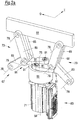
- the drive 63 comprises a servomotor 71, the output shaft 69 of which is shown only by a dashed line and is coupled to a gear unit 72 flanged to the motor 71 in such a way that the output shaft 69 of the motor 71 forms the input element of the gear unit 72.
- the gear unit 72 is designed in such a way that a drive shaft 105, which forms the output member of the gear unit 72, runs with an axis of rotation 107 perpendicular to the output shaft 69 of the motor 71.
- the frame of the workstation includes two guide plates 101 spaced apart in the longitudinal direction T, of which in FIG Fig. 1a and 1b only the rear guide plate 101 is shown here.
- the drive 63 is arranged in a stationary manner on the frame 47 via the gear unit 72.
- the rotary movement of the drive shaft 105 is transmitted via a belt drive, which is only partially shown here, to a rotor 65 whose axis of rotation 75 runs parallel to the drive shaft 105 and thus also parallel to the longitudinal direction T and thus in the horizontal direction.
- the belt drive mentioned in Fig. 1a and 1b a drive shaft 109 and a toothed belt 77 coupling the drive shaft 109 to the rotor 75 are shown.
- the drive shaft 109 on the back of the guide plate 101 is connected to the drive shaft 105 of the gear unit 72 via a further toothed belt.
- a working unit 61 here represented by a beam extending in the transverse direction Q, which is provided with one or more working tools (not shown), e.g. a punching or perforating tool, can be raised and lowered in the vertical direction to perform a working movement.
- the upward movement of the working unit 61 is also referred to as the working stroke.
- the servomotor 71 is controlled in the respective direction of rotation, the resulting rotational movement of the rotor 65 being transmitted to the working unit 61 by means of a gear 67, which here has two gear parts 73 which are spaced apart in the transverse direction Q and have the same structure comprises, between which the rotor 65 is arranged centrally.
- This gear 67 which includes the two gear parts 73, is a planar coupling gear which is acted upon by the central rotor 65, which moves vertically during the working stroke.
- All joint axes 79 of each gear part 73 run horizontally and thus likewise parallel to the axis of rotation 75 of the rotor 65 and to the axis of rotation 107 of the output shaft 105 of the gear unit 72.
- Each gear part 73 comprises a toggle lever arrangement of two parallel straight couplings 85, two parallel curved links 81 and a straight rocker 83.
- the gear thus comprises a double toggle lever arrangement, the toggle levers of the two gear parts 73 each moving during the working stroke move outwardly away from the axis of rotation 75 of the rotor 65 and thus in opposite directions.
- the rocker 83 is articulated to the frame 47 at one end (cf. the configuration according to FIGS Figures 1c-1e ) and at the other end articulated to the link arrangement 81 and the coupling arrangement 85.
- the three components of the coupling gear, namely rocker arm 83, link 81 and coupling 85, are in the embodiment of Fig. 1 , so in both configurations according to Fig. 1a and 1b on the one hand and Figures 1c-1e on the other hand, articulated to one another at a common point 87, which moves horizontally during the working stroke.
- the rocker 83 is located, viewed in the longitudinal direction T, between the two couplings 85, which in turn are located between the two links 81.
- the two links 81 are each articulated at their other end to one of the two end faces of the rotor 65, specifically at a point spaced apart in the radial direction from the axis of rotation 75 of the rotor 65.
- the two links 81 of the other transmission part 73 engage at each diametrically opposite point with respect to the axis of rotation 75 of the rotor 65.
- Fig. 1a shows, in which the working unit 61 is shown in its lowered position, the links 81 of the two transmission parts 73 are curved in such a way that the two toggle lever assemblies assume a compact overall configuration in this bent state.
- the two coupling arrangements 85 of the transmission parts 73 are each articulated to the working unit 61 at points spaced apart in the transverse direction Q.
- both gear parts 73 can consequently be acted upon synchronously in order to act in the same way on the working unit 61 at two points spaced apart in the transverse direction.
- a force to be transmitted by means of the working unit 71 can consequently be applied to a counter-tool or an abutment, evenly distributed in the transverse direction Q, with a material web to be processed, for example a film web of a thermoforming packaging machine to be cut or punched in between.
- FIG Figure 1b The working position with the working unit 61 raised to the maximum and consequently extended toggle lever arrangements is shown in FIG Figure 1b , in which only the axes of rotation are designated for the sake of clarity, namely the horizontal joint axes 79 of the coupling gear formed by the two gear parts 73, the axis of rotation 75 of the rotor 65 and the axis of rotation 107 of the drive shaft 105 of the gear unit 72 connected to the servo motor 71.
- Figure 1c shows that the work station has a length measured in the working or transport direction T, which is referred to here as the longitudinal direction, which is significantly smaller than the width measured in the transverse direction Q, which corresponds to the working width of the respective packaging machine.
- the workstation according to the invention can consequently be built very narrow.
- rollers 113 which are each attached to the outside of the two guide plates 101 and thus the under among other things, guide the guide plates 101 and the rotor 65 comprehensive arrangement when raising and lowering the working unit 61 in the vertical direction.
- elongated holes formed in the guide plates 101 and serving as guide tracks 89 remain in a horizontal orientation during the up and down movement.
- the drive 63 is shown with an inclined output shaft 69.
- the gear unit 72 is provided with a horizontally running drive shaft 105, so that the drive 63 is opposite Fig. 1 and 1b Can be arranged rotated orientation about the axis of rotation 107 of the drive shaft 105.
- Such a positioning of the drive 63 is in the embodiment according to FIGS Figures 1c-1e intended.
- the output shaft 69 of the servomotor 71 extends here in the horizontal direction parallel to the transverse direction Q.
- the drive 63 is arranged between the two planes spaced apart in the longitudinal direction T and defined by the two guide plates 101. How Fig. 1e shows are on the outside of the in Fig. 1d rear guide plate 101 has two gears 105a and 109a, which sit on the respective drive shaft 105 and 109 and are connected to one another by a toothed belt 76. In the area between the two guide plates 101, the shaft 109 drives the rotor 65 via a further toothed belt 77 (cf. Fig. 1d ).
- the drive with motor 71 and gear unit 72 also moves in the vertical direction.
- the gear unit 72 is equipped with the in Fig. 1d rear guide plate 101 firmly connected.
- the rotor 65 is oriented differently, namely with a vertically extending axis of rotation 75.
- the axis of rotation 75 of the rotor 65 and the axis of rotation of the output shaft 69 of the servo motor 71 coincide in this embodiment.
- the servomotor 71 and the rotor 65 which follow one another directly in the axial and here vertical directions, thus form a compact unit.
- a gear unit between the output shaft 69 of the servo motor 71 and a shaft of the rotor 65 can be provided and then integrated into the rotor 65, for example. However, such a gear unit is not mandatory.
- the gear 67 again comprising two similar gear parts 73 between rotor 65 on the one hand and working unit 61 on the other hand is designed in this embodiment as a spatial coupling gear with double toggle lever arrangement.
- the rotor 65 is again arranged centrally between the two gear parts 73.
- the gear parts 73 in turn each comprise a toggle lever arrangement with two parallel straight couplings 85 and a rocker 83 articulated on the frame 47, not shown. Furthermore, each gear part 73 comprises a link 81, which on one side with the upper end of the rotor 65 and is articulated on the other side with the rocker 83, in each case via a ball joint 91.
- the two links 81 are connected to one another on the upper end of the rotor 65 by a rigid connecting piece 125. This ensures a high level of stability and ensures that, in spite of the high forces that act in particular on the articulation points of the rotor 65 for the link 81, no deformations that impair the movement sequence of the lifting mechanism occur.
- the rotor 65 is in turn set in rotation in order to lower or raise the working unit 61 depending on the direction of rotation. Shows the lowered position with bent toggle lever arrangements Fig. 2a , while Figure 2b each shows the toggle lever arrangements in an extended position in which the working unit 61 is raised to the maximum.
- the rotor 65 is fixedly attached, ie stationary with respect to the vertical direction, on the frame 47, which is represented here by two guide plates 101 spaced apart in the longitudinal direction T (cf. in particular Figure 3c ).
- the rotor 65 arranged between them is rotatably mounted on these two guide plates 101 and the two gear parts 73 in FIG Cross direction Q guided horizontally.
- guide tracks 89 are again formed in the guide plates 101.
- the gear 67 with the two gear parts 73 is in turn a planar coupling gear with a double toggle lever arrangement. All hinge axes 79 again run parallel to one another and parallel to the axis of rotation 75 of the rotor 65 and thus parallel to the longitudinal direction T.
- the rockers 83 are each articulated to the frame 47 at the lower end and articulated between the two couplings 65, which are each connected to are articulated to the working unit 61 at their upper end.
- the links of the two gear parts 73 each include two articulated link arms 82. At the articulated connection between the two core sections 82, these and thus the respective gear part 73 are positively guided in the aforementioned manner on the two guide plates 101 and thus on the frame 47.
- the part links 82 articulated on the two end faces of the rotor 65 are each designed to be curved.
- the two other part links 82 are straight and each connected to the respective rocker 83 at a point that does not coincide with the articulated connection between rocker 83 and coupling 85.
- this coupling mechanism there are consequently no common points in the sense of the common points 87 of the concept according to FIG Figures 1a-1e .
- the drive for the rotor 65 is only in Figure 3c a drive belt 77 is shown.
- the drive can be based on the concept of Figures 1a-1c be executed. It has to be taken into account here that different from the concept of Figures 1a-1c the rotor 65 is fixedly attached to the frame 47, namely is rotatably mounted between the two guide plates 101 fixed to the frame.
- a servomotor designed as a rotary drive on the one hand and the in Figure 3c
- toothed belt 77 shown can be made in any way.
- the servomotor is preferably arranged in such a way that the axis of rotation of its output shaft lies in a plane that runs perpendicular to the longitudinal direction T.
- the servomotor can be inclined as in the embodiment according to FIG Fig. 1a and 1b or assume a horizontal position as in the embodiment according to FIGS Figures 1c-1e .
- the rotor 65 is in turn arranged with the axis of rotation 75 running horizontally and parallel to the longitudinal direction T and all joint axes 79 of the planar coupling gear 67, which in turn has two gear parts 73 located in the transverse direction Q on both sides of the centrally arranged rotor 65, also run parallel to the axis of rotation 75 of the rotor 65.
- the coupling elements are each designed in two parts and a pair of parallel straight sub-couplers 86, which are articulated to the working unit 61, and a further straight sub-coupler 86, which on the one hand are connected to the first two sub-couplers 86 and on the other hand, is articulated to a pair of straight parallel rockers 83.
- the last-mentioned sub-coupler 86 is located between the respective two sub-couplers 86 or rockers 83.
- the curved links 81 are each articulated to the two rockers 83 at a different point than the sub-coupler 86, so that in this embodiment, too, no joint As with the concept of Figures 1a-1e is provided.
- a special feature of the embodiment of the Figure 4a and 4b consists in that the rotor 65 comprises two disk-shaped rotor parts 66, the axes of rotation 75 of which coincide.
- the two links 81 extend into the axial space 93 between the two rotor parts 66.
- the handlebar 81 of the in Figure 4b right transmission part 73 with the in Figure 4b front rotor disk 66 is articulated which is indicated by the circle shown on the end face of this rotor disk 66, through which the hinge axis 79 runs, while the link 81 of the in Figure 4b left gear part 73 to the in Figure 4b rear rotor disk 66 is articulated. From this joint connection is in Figure 4b only the hinge axis 79 is shown.
- the two links 81 of the two gear parts 73 are each articulated to the rotor 65 at a point radially spaced from the axis of rotation 75 - in this case to a respective rotor part 66, these two points being diametrically opposite one another , so are spaced apart from one another by 180 ° in the circumferential direction about the axis of rotation 75.
- Figure 4a again shows the working unit 61 in the most lowered position with toggle lever arrangements in the bent state, which are also implemented in this exemplary embodiment by the two gear parts 73.
- Figure 4b again shows the stretched state with the working unit 61 in the highest position.
- the two parts 66 of the rotor 65 are in principle rotatably mounted independently of one another, but nevertheless coupled to one another by a common toothed belt 77 in such a way that the two rotor parts 66 are only synchronized, but rotated in opposite directions, i.e. with opposite directions of rotation.
- the drive 63 comprises a single common toothed belt 77 which forms a loop 95, 97 at each of its two ends and rotates for this purpose is, the belt 77 in the area between the two loops 95, 97 wraps around both rotor parts over part of the circumference.
- the rotor parts 66 are provided with a toothing for the toothed belt 77 on their outer circumference.
- the drive 63 further comprises a servomotor, not shown, designed as a rotary drive, which drives a drive pinion, either directly or via a gear part, around which one of the two loops 95, 97 revolves.
- the respective other loop 97 or 95 runs around a deflection, not shown, which is preferably not driven and which is, for example, a freely rotatably mounted gear.
- the two gear parts 73 can be acted upon synchronously by means of rotors 66 rotating in opposite directions, which are rotated synchronously in opposite directions by means of a single toothed belt 77 having the aforementioned special course.
- FIGS. 5a and 5b illustrate schematically the possible configuration of the gear 67 between drive 63 and working unit 61 as a so-called Watt's planetary gear.
- a section 115 of a planetary gear is formed at one end of an elongated coupling 85 and meshes with a rotor 65, which is designed as a gear and is driven directly by means of the output shaft 69 of the servo motor 71.
- the interposition of a gear unit between motor 71 and rotor 65 is possible, but not mandatory.
- the section 115 moves on a circular path around the axis of rotation 75 of the rotor 65.
- the coupling 85 remains in a plane running perpendicular to the axis of rotation 75 of the rotor 65 and thus perpendicular to the transverse direction Q, but changes its orientation with respect to the vertical direction. This is done through an articulated connection 117 between the upper end of the coupling 85 and the working unit 61 compensated.
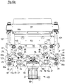
- Figures 6a to 6h are based for the lower working unit 61 on the concept of Figures 2a to 2c . This is consequently not dealt with in more detail, but rather the explanations relating to the Figures 2a to 2c referenced.
- the Figures 6c to 6h are only partial representations, each only showing parts of the in Figure 6a and FIG. 6b, respectively, wherein in particular of the upper working unit 64 only the support rods 121 and the carriers 123 are shown.
- the two gear parts 73 for the lower working unit 61 form a first gear section with the at Figures 2a to 2c described structure.
- a second gear section is provided with two gear parts 73a, each of which is designed analogously to the corresponding gear part 73 of the first gear section, ie a link 81a, a rocker 83a and a coupling 85a.
- the link 81a comprises two articulated part links - insofar as the link 81 according to FIG Figures 3a to 3c .
- Each partial link 81a, the rocker 83a and the coupling 85a each consist of two parallel parts.
- the gear parts 73, 73a are connected in series with respect to the rotor 65 insofar as the movement of the gear part 73a is derived from the movement of the gear part 73: the link 81a is articulated at one end with the rocker arm 83 and at the other end articulated with the rocker arm 83a and the coupling 85a connected.
- the articulated connection to its coupling 85 for the lower working unit 61 lies above the articulated connection between the frame 47 and its rocker 83, while conversely, for the upper working unit 64, the articulated connection of which to its coupling 85a is below the articulated connection between the frame 47 and its rocker 83a.
- the support rods 121 are each coupled to a carrier 123 which is hingedly connected to the free end of the coupling 85a and is thus moved in the vertical direction by means of the coupling 85a.
- Analogous to the stabilization on the rotor 65 by the connecting piece 125 - as above in connection with Figure 2c explained - are the coupling 85a of the two gear parts 73a by a rigid connecting piece 125a (cf. in particular Figures 6e and 6f ) connected with each other.
- the coupling 85a can be rotated relative to the carrier 123 and relative to the connecting piece 125a about the same horizontal joint axis 79.
- the two working units 61, 64 are moved towards one another into a closed position ( Figure 6a , 6c , 6e , 6g ) or in an open position ( Figure 6b , 6d , 6f , 6h ) emotional.
- the lower working unit 61 is guided on the frame 47 via rollers 113 attached to a strut 62, with FIG Figures 6c and 6d only the strut 62, but not the lower working unit 61, is shown, so that in particular in FIG Fig. 6d an otherwise largely covered wall 127 is visible.
- the lower working unit 61 is provided with a lower working tool 61a - here a punching tool - and the upper working unit 64 with an upper working tool 64a - here a counter-punching tool for the lower punching tool 61a.
- the two tools 61a, 64a act when the closed one is reached Position together in order, for example, to separate packages not shown here, as explained in the introductory part as an application example for the invention.
Abstract
Die Erfindung betrifft eine Arbeitsstation, insbesondere Schneid-, Stanz-, Loch-, Form-, Tiefzieh- oder Siegelstation, für eine Verpackungsmaschine, insbesondere für eine Tiefziehverpackungsmaschine, mit einem am Boden abgestützten Gestell, zumindest einer Arbeitseinheit mit einem Arbeitswerkzeug, und zumindest einem am Gestell abgestützten Hubmechanismus, mit dem die Arbeitseinheit zur Ausführung eines Arbeitshubs relativ zu dem Gestell angehoben und abgesenkt werden kann, wobei der Hubmechanismus einen Antrieb (63), einen Rotor (65) und ein Getriebe (67) umfasst, wobei der Rotor mittels des Antriebs zum Anheben der Arbeitseinheit in die eine Richtung und zum Absenken der Arbeitseinheit in die entgegengesetzte Richtung drehbar ist, wobei das Getriebe eingangsseitig mit dem Rotor und ausgangsseitig mit der Arbeitseinheit verbunden ist, und wobei der Antrieb ein Drehantrieb mit einem rotierenden Antriebsorgan ist, insbesondere einem Läufer oder einer Ausgangswelle eines Elektromotors, wobei die Drehbewegung des Ausgangsorgans auf den Rotor übertragen wird.The invention relates to a work station, in particular a cutting, punching, perforating, forming, deep-drawing or sealing station, for a packaging machine, in particular for a deep-drawing packaging machine, with a frame supported on the floor, at least one working unit with a working tool, and at least one on the frame supported lifting mechanism, with which the working unit can be raised and lowered relative to the frame for performing a working stroke, the lifting mechanism comprising a drive (63), a rotor (65) and a gear (67), the rotor by means of the Drive for lifting the working unit in one direction and for lowering the working unit is rotatable in the opposite direction, the transmission being connected on the input side to the rotor and on the output side to the working unit, and the drive being a rotary drive with a rotating drive element, in particular one Rotor or an output shaft of an electric motor, w obei the rotary motion of the output member is transmitted to the rotor.
Description
Die Erfindung betrifft eine Arbeitsstation für eine Verpackungsmaschine, mit einem am Boden abgestützten Gestell, zumindest einer Arbeitseinheit mit einem Arbeitswerkzeug, und zumindest einem am Gestell abgestützten Hubmechanismus, mit dem die Arbeitseinheit zur Ausführung eines Arbeitshubs relativ zu dem Gestell angehoben und abgesenkt werden kann. Bei der Verpackungsmaschine handelt es sich insbesondere um eine Tiefziehverpackungsmaschine.The invention relates to a work station for a packaging machine, with a frame supported on the floor, at least one working unit with a work tool, and at least one lifting mechanism supported on the frame, with which the working unit can be raised and lowered relative to the frame for performing a working stroke. The packaging machine is in particular a thermoforming packaging machine.
Verpackungsmaschinen, mit denen Verpackungen hergestellt, insbesondere aus Materialbahnen wie beispielsweise Folienbahnen, und gleichzeitig mit zu verpackenden Produkten, wie beispielsweise Lebensmittel, gefüllt werden, führen eine Vielzahl von Arbeitsschritten an mehreren unterschiedlichen Arbeitsstationen aus, die in einer Transport- oder Längsrichtung der Verpackungsmaschine verteilt angeordnet sind.Packaging machines with which packaging is produced, in particular from material webs such as film webs, and at the same time filled with products to be packaged, such as food, perform a multitude of work steps at several different work stations, which are distributed in a transport or longitudinal direction of the packaging machine are.
In vielen Fällen werden in einer Unterfolie auch als Mulden bezeichnete Vertiefungen ausgebildet. Dies erfolgt an einer sogenannten Formstation, bei der es sich insbesondere um eine Tiefziehstation handelt. An einer stromabwärts gelegenen Siegelstation wird eine zuvor auf die Unterfolie aufgebrachte Oberfolie mit der Unterfolie verbunden, was typischerweise durch einen thermischen Prozess erfolgt, der als Versiegeln bezeichnet wird. An stromabwärts der Siegelstation gelegenen Arbeitsstationen werden die Verpackungen vereinzelt. Dies erfolgt insbesondere durch Schneid- oder Stanzwerkzeuge. Weitere Arbeitsstationen, die insbesondere stromaufwärts der Siegelstation angeordnet sind, können dazu dienen, die Unterfolie und/oder die Oberfolie sowie gegebenenfalls vorgesehene Zwischenfolien mit Lochungen zu versehen, die beispielsweise in der Siegelstation zum Evakuieren und Begasen der Verpackungen dienen.In many cases, depressions also known as depressions are formed in a lower film. This takes place at a so-called forming station, which is in particular a deep-drawing station. At a downstream sealing station, an upper film previously applied to the lower film is bonded to the lower film, which is typically done by a thermal process known as sealing. The packs are separated at work stations located downstream of the sealing station. This is done in particular by cutting or punching tools. Further work stations, which are arranged in particular upstream of the sealing station, can serve to include the lower film and / or the upper film and any intermediate films provided To provide perforations, which are used, for example, in the sealing station for evacuating and gassing the packaging.
Die Arbeitsstationen einer Verpackungsmaschine umfassen typischerweise zumindest ein Arbeitswerkzeug, das zum Ausführen eines Arbeitsschrittes angehoben wird, um mit einem Gegenwerkzeug zusammenzuwirken. Bei dem Gegenwerkzeug kann es sich um ein einfaches Widerlager oder ein eine zusätzliche Arbeitsfunktion ausführendes Werkzeug handeln. Auch das Gegenwerkzeug kann zur Ausführung eines Arbeitsschrittes eine Hubbewegung ausführen.The work stations of a packaging machine typically include at least one work tool, which is raised to perform a work step in order to interact with a counter-tool. The counter-tool can be a simple abutment or a tool that performs an additional work function. The counter-tool can also perform a lifting movement to carry out a work step.
Während die jeweilige Arbeitsbreite der Verpackungsmaschine, also deren quer zur Transportrichtung der Materialbahnen und somit quer zur Arbeits- oder Längsrichtung der Verpackungsmaschine gemessene Abmessung, einen entsprechenden Bauraum für die Arbeitsstationen zur Verfügung stellt, ist der zur Verfügung stehende Bauraum in Transport- oder Längsrichtung für den Hubmechanismus der Arbeitsstation regelmäßig stark beschränkt.While the respective working width of the packaging machine, i.e. its dimension measured transversely to the transport direction of the material webs and thus transversely to the working or longitudinal direction of the packaging machine, provides a corresponding installation space for the workstations, the installation space available in the transport or longitudinal direction is for the The lifting mechanism of the workstation is regularly very limited.
Der Konstrukteur einer Verpackungsmaschine oder einer Arbeitsstation für eine Verpackungsmaschine sieht sich also mit dem Problem konfrontiert, einen Hubmechanismus bereitstellen zu müssen, der zumindest in Längsrichtung relativ wenig Bauraum benötigt, gleichzeitig aber in der Lage ist, vergleichsweise hohe Kräfte zu übertragen. Bekannte Lösungen setzen beispielsweise pneumatische Antriebe oder elektrische Linearantriebe oder sogenannte Elektrozylinder ein. Hierzu wird beispielsweise auf
Aufgabe der Erfindung ist es, eine Arbeitsstation der eingangs genannten Art derart weiterzubilden, dass bei möglichst geringem Platzbedarf insbesondere in Längsrichtung der Arbeitshub der Arbeitseinheit möglichst flexibel gesteuert werden kann, wobei gleichzeitig sichergestellt sein muss, dass eine ausreichende Stabilität gegeben ist, um möglichst große Kräfte übertragen zu können.The object of the invention is to develop a workstation of the type mentioned at the outset in such a way that, with as little space as possible, especially in The longitudinal direction of the working stroke of the working unit can be controlled as flexibly as possible, while at the same time it must be ensured that there is sufficient stability in order to be able to transmit the greatest possible forces.
Die Lösung dieser Aufgabe erfolgt durch die Merkmale des Anspruchs 1.This problem is solved by the features of claim 1.
Insbesondere ist erfindungsgemäß vorgesehen, dass der Hubmechanismus einen Antrieb, einen Rotor und ein Getriebe umfasst, wobei der Rotor mittels des Antriebs zum Anheben der Arbeitseinheit in die eine Richtung und zum Absenken der Arbeitseinheit in die entgegengesetzte Richtung drehbar ist, wobei das Getriebe eingangsseitig mit dem Rotor und ausgangsseitig mit der Arbeitseinheit verbunden ist, und wobei der Antrieb ein Drehantrieb mit einem rotierenden Antriebsorgan ist, insbesondere einem Läufer oder einer Ausgangswelle eines Elektromotors, wobei die Drehbewegung des Ausgangsorgans auf den Rotor übertragen wird.In particular, it is provided according to the invention that the lifting mechanism comprises a drive, a rotor and a gear, the rotor being rotatable by means of the drive for lifting the working unit in one direction and for lowering the working unit in the opposite direction, the gearing on the input side with the Rotor and is connected on the output side to the working unit, and wherein the drive is a rotary drive with a rotating drive element, in particular a rotor or an output shaft of an electric motor, the rotary movement of the output element being transmitted to the rotor.
Das erfindungsgemäße Antriebskonzept, bei dem ein Drehantrieb einen Rotor in Drehung versetzt, dessen Drehbewegung auf das Getriebe übertragen wird, bei dem also konsequent Linearantriebe vermieden werden, erlaubt unterschiedliche, an die jeweiligen Anforderungen anpassbare Getriebekonzepte, die aber in jedem Fall Platz sparend und in einer zur Übertragung großer Kräfte ausreichend stabilen Weise ausgebildet sein können.The drive concept according to the invention, in which a rotary drive sets a rotor in rotation, the rotational movement of which is transmitted to the gearbox, in which linear drives are consequently avoided, allows different gearbox concepts that can be adapted to the respective requirements, but which in any case save space and in one can be designed to transmit large forces in a sufficiently stable manner.
Bevorzugte Ausgestaltungen der Erfindung sind auch in den abhängigen Ansprüchen, der nachfolgenden Beschreibung sowie der Zeichnung angegeben.Preferred embodiments of the invention are also given in the dependent claims, the following description and the drawing.
Gemäß einer bevorzugten Ausführungsform umfasst der Antrieb einen Servomotor. Der Einsatz eines derartigen Motors erlaubt eine flexibel gesteuerte Bewegung des Hubmechanismus und somit der Arbeitseinheit. Die Geschwindigkeit der Arbeitseinheit während des Arbeitshubs kann beliebig variiert werden. In Abhängigkeit von der jeweiligen Anwendung kann somit der Arbeitseinheit ein grundsätzlich beliebiger Geschwindigkeitsverlauf vorgegeben werden.According to a preferred embodiment, the drive comprises a servomotor. The use of such a motor allows a flexibly controlled movement of the lifting mechanism and thus of the working unit. The speed of the working unit during the working stroke can be varied as required. Dependent on a fundamentally arbitrary speed profile can thus be specified for the working unit for the respective application.
Bevorzugt erstreckt sich der Hubmechanismus in einer Querrichtung und in einer Längsrichtung, wobei die Ausdehnung des Hubmechanismus in Längsrichtung kleiner ist als in Querrichtung. Insbesondere beträgt die Ausdehnung in Längsrichtung weniger als 1/2 oder weniger als 1/3 oder weniger als 1/4 oder weniger als 1/5 der Ausdehnung in Querrichtung.The lifting mechanism preferably extends in a transverse direction and in a longitudinal direction, the extent of the lifting mechanism in the longitudinal direction being smaller than in the transverse direction. In particular, the extension in the longitudinal direction is less than 1/2 or less than 1/3 or less than 1/4 or less than 1/5 of the extension in the transverse direction.
Vorzugsweise ist der Hubmechanismus in einem gedachten quaderförmigen Raumelement enthalten, das eine in Querrichtung gemessene Breite und eine in Längsrichtung gemessene Länge aufweist, wobei die Länge weniger als 200 mm, vorzugsweise weniger als 140 mm beträgt. Hierdurch kann erreicht werden, dass der Hubmechanismus in Längsrichtung nicht mehr Platz benötigt als eine jeweilige Verpackung, die in einer Verpackungsmaschine hergestellt bzw. mit einem zu verpackenden Produkt gefüllt wird, in welche die Arbeitsstation integriert ist.The lifting mechanism is preferably contained in an imaginary cuboid space element which has a width measured in the transverse direction and a length measured in the longitudinal direction, the length being less than 200 mm, preferably less than 140 mm. In this way it can be achieved that the lifting mechanism does not require more space in the longitudinal direction than a respective package that is produced in a packaging machine or filled with a product to be packaged, in which the work station is integrated.
Bei dem Getriebe des Hubmechanismus handelt es sich insbesondere um ein ebenes oder räumliches Koppelgetriebe. Derartige Getriebe können in vielfältiger Weise aufgebaut sein und somit an unterschiedliche Anforderungen angepasst werden. Die Erfindung erlaubt insofern einen Rückgriff auf bewährte Konstruktionsprinzipien.The gear of the lifting mechanism is in particular a planar or spatial coupling gear. Such transmissions can be constructed in many ways and thus adapted to different requirements. To this extent, the invention allows recourse to proven design principles.
Vorzugsweise umfasst das Getriebe wenigstens eine Kniehebelanordnung, insbesondere eine Doppelkniehebel-Anordnung. Hierdurch kann sich der erfindungsgemäße Hubmechanismus die grundsätzlich bekannten Vorteile des Kniehebel-Konzeptes zunutze machen. Von Vorteil ist insbesondere, dass in der durchgestreckten Stellung, wenn die auf das Getriebe einwirkende Kraft maximal ist, diese nicht vom Antrieb, sondern von den Getriebeelementen aufgenommen werden kann.The transmission preferably comprises at least one toggle lever arrangement, in particular a double toggle lever arrangement. As a result, the lifting mechanism according to the invention can make use of the fundamentally known advantages of the toggle lever concept. It is particularly advantageous that in the extended position, when the force acting on the transmission is at its maximum, it cannot be absorbed by the drive but by the transmission elements.
Gemäß einer bevorzugten Ausgestaltung umfasst das Getriebe zwei, bevorzugt baugleiche, Getriebeteile, die mittels des Rotors parallel beaufschlagt werden. Diese beiden Getriebeteile sind insbesondere bezogen auf die Längsrichtung an der gleichen Position angeordnet und in Querrichtung voneinander beabstandet. Folglich kann in einer vorteilhaften Ausgestaltung vorgesehen sein, dass in Querrichtung des Hubmechanismus gesehen der Rotor zwischen den beiden Getriebeteilen angeordnet ist. Bevorzugt ist der Rotor mittig zwischen den beiden Getriebeteilen angeordnet. Es lässt sich folglich ein insofern symmetrischer Aufbau realisieren, der die zur Verfügung stehende Breite nutzt und gleichzeitig eine gleichmäßige Beaufschlagung der Arbeitseinheit gewährleistet.According to a preferred embodiment, the transmission comprises two, preferably structurally identical, transmission parts which are acted upon in parallel by means of the rotor. These two transmission parts are arranged in the same position in particular in relation to the longitudinal direction and are spaced apart from one another in the transverse direction. Consequently, it can be provided in an advantageous embodiment that the rotor is arranged between the two transmission parts, viewed in the transverse direction of the lifting mechanism. The rotor is preferably arranged centrally between the two transmission parts. A structure that is symmetrical in this respect can consequently be implemented, which uses the available width and at the same time ensures that the working unit is applied evenly.
Vorzugsweise sind die beiden Getriebeteile mit dem Rotor an unterschiedlichen Eingangsstellen verbunden, die vorzugsweise bezüglich einer Drehachse des Rotors auf dem gleichen Radius liegen und um 180° gegeneinander versetzt sind.The two gear parts are preferably connected to the rotor at different entry points, which preferably lie on the same radius with respect to an axis of rotation of the rotor and are offset from one another by 180 °.
Unabhängig davon, ob das Getriebe zwei, bevorzugt baugleiche, Getriebeteile umfasst oder nicht, kann generell gemäß einem Ausführungsbeispiel vorgesehen sein, dass der Hubmechanismus bezüglich der Drehachse des Rotors einen symmetrischen Aufbau aufweist.Regardless of whether the transmission comprises two, preferably structurally identical, transmission parts or not, it can generally be provided according to an exemplary embodiment that the lifting mechanism has a symmetrical structure with respect to the axis of rotation of the rotor.
Gemäß einem bevorzugten Aufbaukonzept umfasst das Getriebe oder jeder einer Mehrzahl von das Getriebe bildenden Getriebeteilen zumindest einen mit dem Rotor gelenkig verbundenen Lenker, wenigstens eine mit dem Gestell gelenkig verbundene Schwinge und zumindest eine mit der Arbeitseinheit gelenkig verbundene Koppel. Durch die Positionierung der Anlenkstellen kann das kinematische Verhalten des Getriebes gezielt vorgegeben werden. Die Schwinge sorgt für die Abstützung am Gestell. Der Rotor kann - je nach konkreter Ausgestaltung des Hubmechanismus - stationär bezüglich des Gestells angeordnet sein oder die Hubbewegung relativ zu dem Gestell mitmachen.According to a preferred structural concept, the gearbox or each of a plurality of gearbox parts forming the gearbox comprises at least one link articulated to the rotor, at least one rocker articulated to the frame and at least one link articulated to the working unit. By positioning the articulation points, the kinematic behavior of the transmission can be specified in a targeted manner. The swing arm provides support on the frame. The rotor can - depending on the specific design of the lifting mechanism - be arranged stationary with respect to the frame or it can participate in the lifting movement relative to the frame.
Die Anlenkung des Lenkers an den Rotor erfolgt insbesondere an einer von der Drehachse des Rotors beabstandeten Stelle. In Abhängigkeit von der jeweils gewünschten Kinematik des Getriebes kann der mit dem Rotor verbundene Lenker einen gekrümmten Verlauf aufweisen. Die Schwinge und die Koppel können die gleiche Länge aufweisen, wobei dies aber nicht zwingend ist.The linkage is articulated to the rotor in particular at a point spaced apart from the axis of rotation of the rotor. Depending on the particular desired kinematics of the transmission, the link connected to the rotor can have a curved course. The rocker arm and the coupling can have the same length, but this is not mandatory.
Gemäß einem weiteren Ausführungsbeispiel ist vorgesehen, dass der Maximalhub der Arbeitseinheit einer Drehung des Rotors um nicht mehr als 180° entspricht. Unter anderem kann hierdurch der Rotor dazu benutzt werden, gleichzeitig zwei an unterschiedlichen Stellen gelenkig angelenkte Lenker zu beaufschlagen, die jeweils einem von zwei das Getriebe bildenden, insbesondere baugleichen, Getriebeteilen zugeordnet sind.According to a further exemplary embodiment, it is provided that the maximum stroke of the working unit corresponds to a rotation of the rotor by no more than 180 °. In this way, among other things, the rotor can be used to simultaneously act on two links which are articulated at different points and which are each assigned to one of two gear parts forming the gear, in particular structurally identical.
Bevorzugt wirkt der Antrieb mit dem Rotor über zumindest einen Riemen zusammen, insbesondere über zumindest einen Zahnriemen. Dies erhöht die Flexibilität bei der Positionierung eines den Antrieb bildenden oder zum Antrieb gehörenden Antriebsmotors und des Rotors. Das Antriebsorgan des Antriebs, insbesondere ein Läufer oder eine Ausgangswelle eines den Antrieb bildenden oder zum Antrieb gehörenden Elektromotors, muss nicht direkt über genau einen Antriebsriemen mit dem Rotor zusammenwirken. Es können eine oder mehrere Antriebswellen zwischengeschaltet sein. So kann beispielsweise eine erste zwischengeschaltete Antriebswelle, die sich in Längsrichtung erstreckt, an einer ersten Stelle in Längsrichtung gesehen über einen Antriebsriemen mit dem Antriebsorgan des Antriebs zusammenwirken und an einer axial in Längsrichtung beabstandeten zweiten Stelle mittels eines weiteren Antriebsriemens entweder den Rotor oder eine weitere zwischengeschaltete Antriebswelle beaufschlagen. Auf diese Weise kann der in Längsrichtung zur Verfügung stehende Bauraum genutzt werden, um die Antriebsbewegung des Antriebsorgans des Antriebs auf den Rotor zu übertragen, was wiederum eine höhere Flexibilität bei der Anordnung der einzelnen Komponenten des Hubmechanismus erlaubt.The drive preferably interacts with the rotor via at least one belt, in particular via at least one toothed belt. This increases the flexibility in the positioning of a drive motor forming the drive or belonging to the drive and the rotor. The drive element of the drive, in particular a rotor or an output shaft of an electric motor forming the drive or belonging to the drive, does not have to interact directly with the rotor via precisely one drive belt. One or more drive shafts can be interposed. For example, a first intermediate drive shaft, which extends in the longitudinal direction, can interact at a first point in the longitudinal direction via a drive belt with the drive element of the drive, and at a second point axially spaced in the longitudinal direction, either the rotor or a further intermediate drive is possible by means of a further drive belt Pressurize the drive shaft. In this way, the installation space available in the longitudinal direction can be used to transmit the drive movement of the drive element of the drive to the rotor, which in turn allows greater flexibility in the arrangement of the individual components of the lifting mechanism.
Die Flexibilität lässt sich alternativ oder zusätzlich dadurch erhöhen, dass gemäß einer weiteren Ausgestaltung der Erfindung der Antrieb einen Antriebsmotor mit einer Ausgangswelle umfasst, die den Eingang einer dem Motor zugeordneten Getriebeeinheit bildet, deren Ausgangswelle senkrecht zur Ausgangswelle des Motors verläuft. Hierdurch kann die Ausgangswelle des Motors senkrecht zur Längsrichtung der Arbeitsstation verlaufen, und die Ausgangswelle des Getriebeteils kann sich in Längsrichtung erstrecken. Besonders vorteilhaft ist dies dann, wenn die Drehachse des Rotors sich ebenfalls in Längsrichtung erstreckt. Die Übertragung der Drehbewegung des Antriebsmotors auf den Rotor kann hierdurch besonders kompakt mit minimalem Platzbedarf in Längsrichtung und unter Ausnutzung des in Querrichtung zur Verfügung stehenden Bauraumes gestaltet werden.The flexibility can alternatively or additionally be increased in that, according to a further embodiment of the invention, the drive comprises a drive motor with an output shaft which forms the input of a gear unit assigned to the motor, the output shaft of which runs perpendicular to the output shaft of the motor. As a result, the output shaft of the motor can run perpendicular to the longitudinal direction of the work station, and the output shaft of the transmission part can extend in the longitudinal direction. This is particularly advantageous when the axis of rotation of the rotor also extends in the longitudinal direction. The transmission of the rotary movement of the drive motor to the rotor can thereby be designed to be particularly compact with minimal space requirement in the longitudinal direction and by utilizing the installation space available in the transverse direction.
Je nach konkreter Ausgestaltung des Hubmechanismus können erfindungsgemäß der Antrieb und der Rotor entweder beide stationär bezüglich des Gestells angeordnet sein oder gemeinsam eine Hubbewegung relativ zu dem Gestell ausführen.Depending on the specific design of the lifting mechanism, according to the invention, the drive and the rotor can either both be arranged stationary with respect to the frame or jointly perform a lifting movement relative to the frame.
Gemäß einer bevorzugten Ausgestaltung ist vorgesehen, dass die Arbeitseinheit ausschließlich von dem Hubmechanismus getragen ist. Hierbei ist es folglich nicht erforderlich, die Arbeitseinheit direkt am Gestell abzustützen.According to a preferred embodiment it is provided that the working unit is carried exclusively by the lifting mechanism. It is consequently not necessary to support the working unit directly on the frame.
Gemäß einer weiteren möglichen Ausführungsform der Erfindung ist vorgesehen, dass das Getriebe ein Koppelgetriebe ist, dessen horizontale Gelenkachsen parallel zur Drehachse des Rotors verlaufen. Hierbei können folglich die Gelenkachsen des Koppelgetriebes sowie die Drehachse des Rotors parallel zueinander und in Längsrichtung der Arbeitsstation orientiert sein.According to a further possible embodiment of the invention it is provided that the gear is a coupling gear, the horizontal joint axes of which run parallel to the axis of rotation of the rotor. The joint axes of the coupling mechanism and the axis of rotation of the rotor can consequently be oriented parallel to one another and in the longitudinal direction of the work station.
In einer solchen Situation kann vorgesehen sein, dass ein mit dem Rotor an einer von der Drehachse des Rotors beabstandeten Stelle gelenkig verbundener Lenker oder Teillenker des Getriebes einen gekrümmten Verlauf aufweist.In such a situation, it can be provided that a link or partial link of the transmission articulated to the rotor at a point spaced apart from the axis of rotation of the rotor has a curved profile.
In einer weiteren möglichen Ausgestaltung umfasst das Getriebe zwei baugleiche Getriebeteile, die mittels des Rotors parallel beaufschlagt werden und jeweils einen mit dem Rotor gelenkig verbundenen Lenker, eine mit dem Gestell gelenkig verbundene Schwinge und eine mit der Arbeitseinheit gelenkig verbundene Koppel umfassen, wobei der Lenker, die Schwinge und die Koppel an einer gemeinsamen Stelle miteinander gelenkig verbunden sind, die am Gestell entlang einer, vorzugsweise geradlinigen und insbesondere horizontalen, Bahn zwangsgeführt ist.In a further possible embodiment, the transmission comprises two identical transmission parts which are acted upon in parallel by means of the rotor and each comprise a link articulated to the rotor, a rocker articulated to the frame and a coupling articulated to the working unit, the link, the rocker arm and the coupling are connected to one another in an articulated manner at a common point, which is forcibly guided on the frame along a preferably straight and in particular horizontal path.
Bei einem solchen Konzept, aber nicht ausschließlich bei einem solchen Konzept, kann es vorteilhaft sein, wenn auch der Rotor während des Arbeitshubs eine Hubbewegung relativ zu dem Gestell ausführt.With such a concept, but not exclusively with such a concept, it can be advantageous if the rotor also performs a lifting movement relative to the frame during the working stroke.
Alternativ kann der Rotor stationär bezüglich des Gestells angeordnet sein, wobei der Lenker wenigstens zwei gelenkig miteinander verbundene Teillenker umfasst, von denen der eine gelenkig mit dem Rotor und der andere mit einer anderen Komponente des Getriebes gelenkig verbunden ist.Alternatively, the rotor can be arranged stationary with respect to the frame, the link comprising at least two articulated part links, of which one is articulated to the rotor and the other is articulated to another component of the transmission.
Bei einer anderen möglichen Ausgestaltung des erfindungsgemäßen Hubmechanismus ist vorgesehen, dass das Getriebe ein räumliches Koppelgetriebe ist, bei dem die Gelenkachsen zwischen Arbeitseinheit und Koppel, zwischen Gestell und Schwinge und zwischen Koppel und Schwinge horizontal verlaufen, bei dem die Drehachse des Rotors vertikal verläuft und bei dem die Lenker mit dem Rotor einerseits und mit der Koppel oder der Schwinge andererseits jeweils durch ein Kugelgelenk verbunden sind.In another possible embodiment of the lifting mechanism according to the invention, it is provided that the transmission is a spatial coupling mechanism in which the joint axes between the working unit and coupling, between frame and rocker and between coupling and rocker run horizontally, in which the axis of rotation of the rotor runs vertically and at which the links are connected to the rotor on the one hand and to the coupling or the rocker on the other hand by a ball joint.
Ein solches Konzept hat unter anderem den Vorteil, dass das Antriebsorgan des Antriebs direkt mit dem Rotor zusammenwirken oder sogar einen Bestandteil des Rotors bilden kann.Such a concept has the advantage, among other things, that the drive element of the drive can interact directly with the rotor or even form a component part of the rotor.
Insbesondere ist eine Ausgestaltung möglich, wonach der Antrieb ein Drehantrieb mit einem rotierenden Antriebsorgan ist, insbesondere einem Läufer oder einer Ausgangswelle eines Elektromotors, wobei die Drehbewegung des Antriebsorgans auf den Rotor übertragen wird, und wobei die Drehachse des Antriebsorgans parallel zur Drehachse des Rotors verläuft und insbesondere mit der Drehachse des Rotors zusammenfällt.In particular, an embodiment is possible according to which the drive is a rotary drive with a rotating drive element, in particular a rotor or an output shaft of an electric motor, the rotational movement of the drive element being transmitted to the rotor, and the axis of rotation of the drive element running parallel to the axis of rotation of the rotor and in particular coincides with the axis of rotation of the rotor.
Folglich kann beispielsweise der Rotor direkt auf die Ausgangswelle eines Elektromotors gesetzt werden. Der Rotor und der Antriebsmotor können so vertikal untereinander und somit insbesondere ohne Versatz in Längsrichtung angeordnet werden, was eine optimale Ausnutzung des in Längsrichtung zur Verfügung stehenden Bauraumes bedeutet.Consequently, for example, the rotor can be placed directly on the output shaft of an electric motor. The rotor and the drive motor can thus be arranged vertically one below the other and thus in particular without offset in the longitudinal direction, which means optimal use of the installation space available in the longitudinal direction.
Gemäß einer weiteren bevorzugten Ausgestaltung der Erfindung umfasst das Getriebe zwei, bevorzugt baugleiche, Getriebeteile, die mittels des Rotors parallel beaufschlagt werden, wobei der Rotor zwei mittels des Antriebs gleichzeitig und gegenläufig drehbare Rotorteile mit zusammenfallenden Drehachsen umfasst, und wobei der eine Rotorteil das eine Getriebeteil und der andere Rotorteil das andere Getriebeteil beaufschlagt. Diese Aufteilung des Rotors in gegenläufig drehbare Rotorteile eröffnet weiteren Spielraum beim Aufbau und bei der Unterbringung des Hubmechanismus in einem vor allem in Längsrichtung beschränkten Bauraum.According to a further preferred embodiment of the invention, the transmission comprises two, preferably structurally identical, transmission parts which are acted upon in parallel by means of the rotor, the rotor comprising two rotor parts which can be rotated simultaneously and in opposite directions by means of the drive and which have coincident axes of rotation, and the one rotor part and the one transmission part and the other rotor part acts on the other gear part. This division of the rotor into rotor parts that can rotate in opposite directions opens up further leeway in the construction and accommodation of the lifting mechanism in an installation space that is primarily restricted in the longitudinal direction.
Insbesondere kann hierbei vorgesehen sein, dass die beiden Rotorteile axial voneinander beabstandet sind und jeder Getriebeteil einen Lenker umfasst, wobei in dem Zwischenraum zwischen den beiden Rotorteilen der eine Lenker mit dem einen Rotorteil und der andere Lenker mit dem anderen Rotorteil gelenkig verbunden ist, und wobei sich die beiden Lenker aus dem Zwischenraum heraus erstrecken und außerhalb des Zwischenraumes jeweils mit einer anderen Komponente des Getriebes gelenkig verbunden sind.In particular, it can be provided that the two rotor parts are axially spaced from one another and each gear part includes a link, with one link articulated to one rotor part and the other link to the other rotor part in the space between the two rotor parts is, and wherein the two links extend out of the space and are each articulated outside the space with a different component of the transmission.
Für die beiden Rotorteile kann ein gemeinsamer Antrieb vorgesehen sein, der gleichzeitig beide Rotorteile mittels eines gemeinsamen Riemens in Drehung versetzt. Vorzugsweise bildet der Riemen zwei Schlaufen, von denen die eine um ein Antriebsorgan des Antriebs und die andere um eine Umlenkung umläuft, wobei der Riemen zwischen den Schlaufen für beide Rotorteile jeweils eine Teilumschlingung bildet. Bei diesem Konzept genügen folglich ein einziger Antrieb und ein einziger Riemen, um zwei Rotorteile gleichzeitig in Drehung zu versetzen. Vorteilhafterweise kann die Anordnung derart gewählt werden, dass die beiden Rotorteile gleichzeitig und gegenläufig gedreht werden.A common drive can be provided for the two rotor parts, which simultaneously causes both rotor parts to rotate by means of a common belt. The belt preferably forms two loops, one of which runs around a drive element of the drive and the other around a deflection, the belt forming a partial loop between the loops for both rotor parts. With this concept, a single drive and a single belt are sufficient to set two rotor parts in rotation at the same time. The arrangement can advantageously be chosen such that the two rotor parts are rotated simultaneously and in opposite directions.
Dies ist insbesondere dann von Vorteil, wenn ein insbesondere symmetrischer Aufbau mit zwischen (in Querrichtung gesehen) zwei Getriebeteilen, die das Getriebe bilden, angeordnetem Rotor vorgesehen ist. Der eine Rotorteil beaufschlagt dann das linke Getriebeteil, während der andere Rotorteil das rechte Getriebeteil beaufschlagt.This is particularly advantageous when a particularly symmetrical structure is provided with a rotor arranged between (seen in the transverse direction) two gear parts that form the gear. One rotor part then acts on the left gear part, while the other rotor part acts on the right gear part.
Bei einer möglichen generellen Anordnung, die für verschiedene der vorstehend erläuterten Konzepte geeignet ist, kann insbesondere vorgesehen sein, dass der Antrieb ein Drehantrieb mit einem rotierenden Antriebsorgan ist, insbesondere einem Läufer oder einer Ausgangswelle eines Elektromotors, wobei die Drehbewegung des Antriebsorgans auf den Rotor übertragen wird, und wobei die Drehachse des Antriebsorgans senkrecht zur Drehachse des Rotors und insbesondere horizontal verläuft.In a possible general arrangement that is suitable for various of the concepts explained above, it can in particular be provided that the drive is a rotary drive with a rotating drive element, in particular a rotor or an output shaft of an electric motor, the rotary movement of the drive element being transmitted to the rotor is, and wherein the axis of rotation of the drive member is perpendicular to the axis of rotation of the rotor and in particular horizontally.
Gemäß einer alternativen Ausgestaltung der Erfindung kann das Getriebe als ein Watt'sches Planetengetriebe ausgebildet ist.According to an alternative embodiment of the invention, the gear can be designed as a Watt's planetary gear.
Ein derartiges Getriebe zeichnet sich durch einen besonders einfachen Aufbau aus, der sich auch deshalb für eine Arbeitsstation der hier in Rede stehenden Art besonders gut eignet, da dieser Aufbau so in der Arbeitsstation angeordnet werden kann, dass wenig Bauraum in Längsrichtung benötigt wird.Such a transmission is characterized by a particularly simple structure, which is therefore particularly well suited for a work station of the type in question here, since this structure can be arranged in the work station in such a way that little installation space is required in the longitudinal direction.
Gemäß einem weiteren Ausführungsbeispiel der Erfindung sind zwei Arbeitseinheiten vorgesehen, nämlich eine untere Arbeitseinheit und eine obere Arbeitseinheit, die mit dem Hubmechanismus gleichzeitig und entgegengesetzt derart bewegbar sind, dass beim Anheben der einen Arbeitseinheit die andere Arbeitseinheit abgesenkt wird, und umgekehrt. Es ist folglich nur ein einziger Antrieb erforderlich, um die beiden Arbeitseinheiten gleichzeitig zu bewegen.According to a further exemplary embodiment of the invention, two working units are provided, namely a lower working unit and an upper working unit, which can be moved simultaneously and in opposite directions with the lifting mechanism in such a way that when one working unit is raised, the other working unit is lowered, and vice versa. As a result, only a single drive is required to move the two working units simultaneously.
Vorzugsweise sind die zwei Arbeitseinheiten zwischen einer offenen Stellung und einer geschlossenen Stellung bewegbar, wobei die Arbeitseinheiten beim Bewegen in die geschlossene Stellung oder bei Erreichen der geschlossenen Stellung mit jeweiligen Werkzeugen gemeinsam eine Bearbeitung vornehmen, insbesondere ein Schneiden, Stanzen, Lochen, Formen, Tiefziehen oder Siegeln.Preferably, the two working units can be moved between an open position and a closed position, the working units jointly undertaking a processing with respective tools when moving into the closed position or when reaching the closed position, in particular cutting, punching, punching, forming, deep drawing or Seal.
Es kann vorgesehen sein, dass das eingangsseitig mit dem Rotor verbundene Getriebe ausgangsseitig sowohl mit der einen Arbeitseinheit als auch mit der anderen Arbeitseinheit verbunden ist, insbesondere an zwei unterschiedlichen Stellen. Mittels eines einzigen Getriebes können hierbei folglich die beiden Arbeitseinheiten gleichzeitig beaufschlagt werden.It can be provided that the transmission connected to the rotor on the input side is connected on the output side to both the one working unit and the other working unit, in particular at two different points. The two working units can consequently be acted upon simultaneously by means of a single gear.
In einem Ausführungsbeispiel umfasst das Getriebe zwei Getriebeabschnitte, von denen der eine Getriebeabschnitt eingangsseitig mit dem Rotor und ausgangsseitig mit der einen, insbesondere der unteren, Arbeitseinheit verbunden ist, und von denen der andere Getriebeabschnitt eingangsseitig mit dem einen Getriebeabschnitt und ausgangsseitig mit der anderen, insbesondere der oberen, Arbeitseinheit verbunden ist. Hierbei kann folglich die Bewegung der anderen Arbeitseinheit von dem Getriebeabschnitt der einen Arbeitseinheit abgeleitet werden. Es ist somit nicht erforderlich, Getriebeabschnitte beider Arbeitseinheiten mit dem Rotor zu verbinden. Mit anderen Worten sind die Getriebeabschnitte der beiden Arbeitseinheiten in Bezug auf deren gemeinsamen Antrieb, insbesondere auf den Rotor, nicht parallel, sondern in Reihe geschaltet.In one embodiment, the gearbox comprises two gearbox sections, of which one gearbox section is connected on the input side to the rotor and on the output side with one, in particular the lower, working unit, and of which the other gearbox section is connected on the input side with one gearbox section and on the output side with the other, in particular the upper, working unit connected is. In this case, the movement of the other working unit can consequently be derived from the gear section of the one working unit. It is therefore not necessary to connect gear sections of both working units to the rotor. In other words, the gear sections of the two working units are not connected in parallel with respect to their common drive, in particular on the rotor, but in series.
Des Weiteren kann vorgesehen sein, dass die beiden Getriebeabschnitte jeweils zumindest ein ebenes oder ein räumliches Koppelgetriebe umfassen. Alternativ oder zusätzlich kann vorgesehen sein, dass die beiden Getriebeabschnitte jeweils wenigstens eine Kniehebelanordnung umfassen, insbesondere jeweils eine Doppelkniehebel-Anordnung.Furthermore, it can be provided that the two gear sections each include at least one planar or one spatial coupling gear. Alternatively or in addition, it can be provided that the two gear sections each include at least one toggle lever arrangement, in particular a double toggle lever arrangement each.
Alternativ oder zusätzlich kann vorgesehen sein, dass die beiden Getriebeabschnitte jeweils zwei, bevorzugt baugleiche, Getriebeteile umfassen, die parallel beaufschlagt werden, wobei die Getriebeteile des einen Getriebeabschnitts mittels des Rotors parallel beaufschlagt werden und die Getriebeteile des anderen Getriebeabschnitts jeweils mittels eines Getriebeteils des einen Getriebeabschnitts beaufschlagt werden, wobei insbesondere die beiden Getriebeteile des anderen Getriebeabschnitts durch ein starres Verbindungsstück miteinander verbunden sind, welches bevorzugt an beiden Getriebeteilen jeweils gelenkig mit einer Koppel des Getriebeteils verbunden ist.Alternatively or additionally, it can be provided that the two gear sections each comprise two, preferably structurally identical, gear parts that are acted upon in parallel, the gear parts of one gear section being acted upon in parallel by means of the rotor and the gear parts of the other gear section each by means of a gear part of one gear section are acted upon, wherein in particular the two gear parts of the other gear section are connected to one another by a rigid connecting piece, which is preferably connected in an articulated manner to a coupling of the gear part on both gear parts.
Ferner kann vorgesehen sein, dass die beiden Getriebeabschnitte jeweils zumindest einen Lenker, wenigstens eine mit dem Gestell gelenkig verbundene Schwinge und zumindest eine mit der jeweiligen Arbeitseinheit gelenkig verbundene Koppel umfassen, wobei bevorzugt für die untere Arbeitseinheit die gelenkige Verbindung zwischen Arbeitseinheit und Koppel oberhalb der gelenkigen Verbindung zwischen Gestell und Schwinge liegt und für die obere Arbeitseinheit die gelenkige Verbindung zwischen Arbeitseinheit und Koppel unterhalb der gelenkigen Verbindung zwischen Gestell und Schwinge liegt, oder umgekehrt. Durch diese unterschiedliche mechanische Verschaltung zwischen Gestell einerseits und jeweiliger Arbeitseinheit andererseits kann erreicht werden, dass eine einzige - und folglich nur einen Richtungssinn aufweisende - Bewegung des gemeinsamen Rotors gleichzeitige gegensinnige Bewegungen der beiden Arbeitseinheiten bewirken kann.Furthermore, it can be provided that the two gear sections each include at least one link, at least one rocker arm articulated to the frame and at least one articulated coupling with the respective working unit, the articulated connection between working unit and coupling above the articulated coupling preferably for the lower working unit Connection between frame and rocker is and for the upper work unit the articulated connection between the work unit and paddock below the articulated Connection between frame and rocker is, or vice versa. Through this different mechanical interconnection between the frame on the one hand and the respective working unit on the other hand, it can be achieved that a single movement of the common rotor - and consequently only having one sense of direction - can bring about simultaneous movements of the two working units in opposite directions.
Insbesondere dann, wenn die Arbeitseinheit selbst vergleichsweise schmal (in Längsrichtung gesehen) ist, beispielsweise dann, wenn die Arbeitseinheit ein Schneid- oder Stanzwerkzeug aufweist, kann es ausreichend sein, wenn für die Arbeitseinheit ein einziger erfindungsgemäßer Hubmechanismus der vorstehend erläuterten Art vorgesehen ist.In particular, when the working unit itself is comparatively narrow (viewed in the longitudinal direction), for example when the working unit has a cutting or punching tool, it may be sufficient if a single inventive lifting mechanism of the type explained above is provided for the working unit.
Dies ist jedoch nicht zwingend. Die Arbeitsstation kann alternativ wenigstens zwei in einer Längsrichtung beabstandete Hubmechanismen gemäß zumindest einer der vorstehend erläuterten Ausgestaltungen aufweisen, also jeweils mit einem Antrieb, einem Rotor und einem Getriebe versehen sein, wobei die Antriebe der Hubmechanismen synchronisiert betreibbar sind, also insbesondere synchron gesteuert werden können, um gemeinsam die Arbeitseinheit anzuheben und abzusenken.However, this is not mandatory. The work station can alternatively have at least two lifting mechanisms spaced apart in a longitudinal direction according to at least one of the configurations explained above, i.e. each provided with a drive, a rotor and a gear, wherein the drives of the lifting mechanisms can be operated in a synchronized manner, i.e. in particular can be controlled synchronously, to raise and lower the working unit together.
Wenn die Arbeitseinheit beispielsweise ein Formwerkzeug, ein Tiefziehwerkzeug oder ein Siegelwerkzeug umfasst, das eine Ausdehnung in Längsrichtung besitzt, die insbesondere deutlich größer ist als die Länge einer Verpackung, dann kann eine derartige Arbeitsstation durch synchrone Steuerung von beispielsweise zwei Hubmechanismen, die in Längsrichtung beabstandet angeordnet sind, angehoben und abgesenkt werden.If the working unit comprises, for example, a molding tool, a deep-drawing tool or a sealing tool that has an extension in the longitudinal direction that is in particular significantly greater than the length of a package, then such a work station can be arranged by synchronous control of, for example, two lifting mechanisms that are spaced apart in the longitudinal direction are raised and lowered.
Dies bedeutet aber nicht, dass für z.B. zum Formen, Tiefziehen oder Siegeln vorgesehene Arbeitsstationen zwangsläufig mehrere in Längsrichtung beabstandete Hubmechanismen der erfindungsgemäßen Art aufweisen müssen. Mehrere Hubmechanismen kommen vielmehr insbesondere dann zum Einsatz, wenn diese Arbeitsstationen sogenannte Formate oder Arrays von Verpackungen gleichzeitig herstellen oder bearbeiten sollen, bei denen mehrere Verpackungen, insbesondere Reihen von Verpackungen, in Längsrichtung hintereinander vorgesehen sind. Ein derartiges formatweises Arbeiten z.B. beim Formen, Tiefziehen und Siegeln ist bei Verpackungsmaschinen häufig vorgesehen, aber keineswegs zwingend.This does not mean, however, that several workstations that are provided for molding, deep-drawing or sealing, for example, are necessarily spaced apart in the longitudinal direction Must have lifting mechanisms of the type according to the invention. Rather, several lifting mechanisms are used in particular when these workstations are to produce or process so-called formats or arrays of packaging at the same time, in which several packaging, in particular rows of packaging, are provided one behind the other in the longitudinal direction. Such format-wise work, for example when forming, deep-drawing and sealing, is often provided for in packaging machines, but is by no means mandatory.
Die Erfindung betrifft außerdem eine Verpackungsmaschine, insbesondere eine Tiefziehverpackungsmaschine, mit zumindest einer erfindungsgemäßen Arbeitsstation.The invention also relates to a packaging machine, in particular a thermoforming packaging machine, with at least one work station according to the invention.
Vorzugsweise ist die Arbeitsstation in einer Arbeitsrichtung der Verpackungsmaschine, die der vorstehend erwähnten Längsrichtung entspricht, einer Siegelstation der Verpackungsmaschine nachgeordnet, wobei die Arbeitsstation zum Bearbeiten einer Materialbahn, insbesondere einer Folienbahn, zum Bearbeiten einer Verpackung oder eines Teils einer Verpackung, oder zum Vereinzeln von Verpackungen ausgebildet.The work station is preferably arranged downstream of a sealing station of the packaging machine in a working direction of the packaging machine that corresponds to the above-mentioned longitudinal direction, the work station for processing a material web, in particular a film web, for processing a packaging or part of a packaging, or for separating packaging educated.
Des Weiteren betrifft die Erfindung die Verwendung einer erfindungsgemäßen Arbeitsstation in einer Verpackungsmaschine, insbesondere einer Tiefziehverpackungsmaschine, zum Bearbeiten einer Materialbahn, insbesondere einer Folienbahn, zum Bearbeiten einer Verpackung oder eines Teils einer Verpackung, oder zum Vereinzeln von Verpackungen.The invention also relates to the use of a work station according to the invention in a packaging machine, in particular a deep-drawing packaging machine, for processing a material web, in particular a film web, for processing a packaging or part of a packaging, or for separating packaging.
Das erwähnte Bearbeiten umfasst insbesondere ein Schneiden, Stanzen, Lochen, Formen, Tiefziehen oder Siegeln.The processing mentioned includes, in particular, cutting, punching, punching, shaping, deep drawing or sealing.
Des Weiteren betrifft die Erfindung die Verwendung eines als Drehantrieb ausgebildeten Servomotors als Antrieb in einem Hubmechanismus der in der vorliegenden Offenbarung beschriebenen Art.The invention also relates to the use of a servo motor designed as a rotary drive as a drive in a lifting mechanism of the type described in the present disclosure.
Die Erfindung wird im Folgenden beispielhaft unter Bezugnahme auf die Zeichnung beschrieben. Es zeigen:
- Fig. 1a-1e
- verschiedene Ansichten eines erfindungsgemäßen Konzeptes, bei dem die Drehachse des Rotors horizontal ausgerichtet ist und der Rotor während des Arbeitshubs ebenfalls eine Hubbewegung ausführt,
- Fig. 2a-2c
- verschiedene Ansichten eines weiteren erfindungsgemäßen Konzeptes, bei dem die Drehachse des Rotors vertikal ausgerichtet ist,
- Fig. 3a-3c
- ein weiteres erfindungsgemäßes Konzept, bei dem die Drehachse des Rotors wiederum horizontal ausgerichtet ist, der Rotor jedoch bezogen auf die vertikale Richtung stationär bezüglich des Gestells angeordnet ist,
- Fig. 4a und 4b
- ein weiteres erfindungsgemäßes Konzept, bei dem die Drehachse des Rotors wiederum horizontal ausgerichtet ist und der Rotor zwei gegenläufig in Drehung versetzbare Rotorteile umfasst,
- Fig. 5a und 5b
- ein erfindungsgemäßes Konzept, bei dem das Getriebe des Hubmechanismus als Watt'sches Planetengetriebe ausgebildet ist,
- Fig. 6a-6h
- ein weiteres erfindungsgemäßes Konzept, bei dem wie beim Konzept der
Fig. 2a-2c die Drehachse des Rotors vertikal ausgerichtet ist und bei dem zwei zusammenwirkende Arbeitseinheiten entgegengesetzte Hubbewegungen ausführen, und - Fig. 7
- schematisch eine Seitenansicht einer Verpackungsmaschine mit mehreren Arbeitsstationen, die jeweils in erfindungsgemäßer Weise ausgebildet sein können.
- Figures 1a-1e
- different views of a concept according to the invention in which the axis of rotation of the rotor is aligned horizontally and the rotor also performs a lifting movement during the working stroke,
- Figures 2a-2c
- different views of a further concept according to the invention, in which the axis of rotation of the rotor is oriented vertically,
- Figures 3a-3c
- Another concept according to the invention in which the axis of rotation of the rotor is again aligned horizontally, but the rotor is arranged stationary with respect to the frame in relation to the vertical direction,
- Figures 4a and 4b
- Another concept according to the invention in which the axis of rotation of the rotor is again aligned horizontally and the rotor comprises two rotor parts that can be rotated in opposite directions,
- Figures 5a and 5b
- a concept according to the invention in which the gear of the lifting mechanism is designed as a Watt's planetary gear,
- Figures 6a-6h
- Another inventive concept in which as in the concept of
Figures 2a-2c the axis of rotation of the rotor is aligned vertically and in which two cooperating working units execute opposite lifting movements, and - Fig. 7
- schematically a side view of a packaging machine with several work stations, which can each be designed in the manner according to the invention.
Um den Aufbau insbesondere des Hubmechanismus besser erläutern zu können, sind bei den einzelnen Darstellungen jeweils bestimmte Bauteile der Arbeitsstation nicht gezeigt. Die Darstellungen zielen insbesondere darauf ab, den grundsätzlichen Aufbau und die Kinematik des Hubmechanismus und insbesondere des jeweils verwendeten Getriebes zu erläutern.In order to better explain the structure of the lifting mechanism in particular, certain components of the workstation are not shown in the individual illustrations. The illustrations aim in particular to explain the basic structure and the kinematics of the lifting mechanism and, in particular, of the gearbox used in each case.
Wie im Einleitungsteil bereits erwähnt, sind die erfindungsgemäßen Arbeitsstationen dazu ausgebildet, in einer Verpackungsmaschine, insbesondere in einer Tiefziehverpackungsmaschine, verwendet zu werden.As already mentioned in the introductory part, the workstations according to the invention are designed to be used in a packaging machine, in particular in a deep-drawing packaging machine.
Um einen Überblick über eine derartige Verpackungsmaschine zu geben, wird zunächst anhand von
Die in
Die Maschine umfasst eine Mehrzahl von in Transportrichtung T aufeinander folgenden Arbeitsstationen, nämlich eine auch als Tiefzieher oder Thermoformer bezeichnete Formstation 11, eine Einbringstation 13 für zu verpackende Produkte 10, eine Zufuhrstation 14 für eine von einer Vorratsrolle 25a abgezogene Oberfolie 25, eine Etikettierstation 16, eine Quertrennstation 17 sowie eine Längstrennstation 19.The machine comprises a plurality of workstations following one another in the transport direction T, namely a forming
Bei den zu verpackenden Produkten 10 handelt es sich beispielsweise um Lebensmittelprodukte, hier in Form von sogenannten Portionen, die jeweils mehrere Scheiben umfassen, welche zuvor mittels eines Lebensmittelslicers (nicht dargestellt) von einem laib- oder riegelförmigen Lebensmittel wie z.B. Wurst, Käse, Schinken oder Fleisch abgetrennt wurden.The
Den Betrieb der Verpackungsmaschine einschließlich der erwähnten Arbeitsstationen steuert eine zentrale Steuereinrichtung 41, die außerdem für eine Regelung zuständig ist, auf welche nachstehend näher eingegangen wird. Zudem ist die Verpackungsmaschine mit einer Bedieneinrichtung 45 versehen, die z.B. einen Touchscreen umfasst, an welchem einem Bediener alle erforderlichen Informationen angezeigt werden können und der Bediener alle notwendigen Einstellungen vor und während des Betriebs der Maschine vornehmen kann.The operation of the packaging machine, including the work stations mentioned, is controlled by a
Aufbau und Funktionsweise der genannten Arbeitsstationen sind dem Fachmann grundsätzlich bekannt, sodass hierauf nicht im Detail eingegangen wird.The structure and mode of operation of the work stations mentioned are fundamentally known to the person skilled in the art, so that they will not be discussed in detail.
An der ein Oberwerkzeug 11a und ein Unterwerkzeug 11b umfassende Formstation 11 werden jeweils in einem Tiefziehprozess in der Unterfolie 23 auch als Mulden bezeichnete Vertiefungen 29 ausgebildet. In diese Vertiefungen 29 werden an der Einbringstation 13 die erwähnten Portionen 10 eingelegt. Die Einbringstation 13 umfasst hier einen sogenannten Einleger, von dem zwei Endlosförderbänder 13a, 13b dargestellt sind. Alternativ oder zusätzlich kann die Einbringstation 13 einen hier ebenfalls schematisch dargestellten Roboter 50 umfassen, z.B. in Form eines sogenannten "Picker", der als Delta-Roboter mit einem Greifer 52, der zwei jeweils eine Portion 10 gemeinsam haltende Schaufeln umfasst, ausgebildet sein kann. Derartige Roboter und deren Einsatz bei der Handhabung von Lebensmitteln, insbesondere beim Einlegen von Portionen in Vertiefungen von Verpackungen, sind dem Fachmann grundsätzlich bekannt, weshalb hier weitergehende Ausführungen nicht erforderlich sind.At the forming
Anschließend werden die mit den gefüllten Vertiefungen 29 versehene Unterfolie 23 und die Oberfolie 25 der Siegelstation 15 zugeführt, die ein Oberwerkzeug 15a und ein Unterwerkzeug 15b umfasst. Mittels dieser Werkzeuge 15a, 15b werden die Oberfolie 25 und die Unterfolie 23 miteinander verbunden. Hierdurch werden die Vertiefungen 29 und somit die von Oberfolie 25 und Unterfolie 23 gebildeten Verpackungen 21 verschlossen. In
Im Anschluss an die Siegelstation 15 hängen die Verpackungen 21 noch durch die Oberfolie 25 und die Unterfolie 23 zusammen, müssen also noch vereinzelt werden. In dem hier dargestellten Ausführungsbeispiel werden die Verpackungen 21 vor dem Vereinzeln an der Etikettierstation 16 mit Etiketten 51 versehen. Alternativ können eine oder mehrere Etikettierstationen 16 stromabwärts der Trennstationen 17, 19 positioniert sein. Des Weiteren können eine oder mehrere Arbeitsstationen vorgesehen sein, an denen die Verpackungen 21 mit einer oder mehreren Bedruckungen 53 versehen werden.Following the sealing
Stromabwärts der Trennstationen 17, 19 können weitere Arbeitsstationen vorgesehen sein, beispielsweise eine Waage zur Gewichtskontrolle der Verpackungen 21.Further work stations can be provided downstream of the separating
An einer Vielzahl von in
So kann eine obere und eine untere Messeinrichtung jeweils unmittelbar hinter der Formstation 11 vorgesehen sein. Jeweils im Anschluss an die Einbringstation 13 kann ebenfalls eine obere und eine untere Messeinrichtung angeordnet sein. Eine weitere Messeinrichtung kann der Zufuhrstation 14 für die Oberfolie 25 zugeordnet sein. Unmittelbar hinter der Siegelstation 15 kann wiederum jeweils eine obere und eine untere Messeinrichtung angeordnet sein. Ebenso können sich jeweils eine obere und eine untere Messeinrichtung an die Etikettierstation 16 anschließen. Des Weiteren kann eine Messeinrichtung stromabwärts der Quertrennstation 17 und eine weitere Messeinrichtung stromabwärts der Längstrennstation 19 angeordnet sein. Eine in Transportrichtung T letzte Messeinrichtung, die keiner der genannten Arbeitsstationen zugeordnet ist, kann zusätzlich vorgesehen sein, um eine von der jeweiligen Anwendung abhängige Vermessung der fertigen Verpackungen 21 durchzuführen. Abweichend hiervon kann die Verpackungsmaschine eine kleinere oder eine größere Anzahl von Messeinrichtungen aufweisen. Insbesondere kann vorgesehen sein, dass nicht hinter jeder Arbeitsstation, sondern nur hinter einigen der Arbeitsstationen jeweils eine oder mehrere Messeinrichtungen vorhanden sind. Des Weiteren ist es möglich, dass in Abhängigkeit von einer jeweiligen Anwendung nur ein Teil der an einer Verpackungsmaschine angebrachten Messeinrichtungen aktiv ist, während die übrigen Messeinrichtungen für die momentane Anwendung nicht verwendet werden.An upper and a lower measuring device can each be provided immediately behind the forming
Anwendungen können sich z.B. hinsichtlich der Art der zu verpackenden Produkte 10, der Größe der Vertiefungen 29 in Längs- und/oder Querrichtung oder hinsichtlich eines Formatsatzes voneinander unterscheiden. Ein Formatsatz bezeichnet hier allgemein eine Gruppe von Items, hier insbesondere sowohl von Portionen 10 als auch Vertiefungen 29 oder Verpackungen 21, die als Ganzes - also formatsatzweise - gehandhabt werden und sich insbesondere durch Anzahl und Abstand von Items in Längs- und Querrichtung voneinander unterscheiden.Applications can be e.g. differ from one another with regard to the type of
So kann z.B. pro Arbeitstakt der Verpackungsmaschine ein Formatsatz von 3 x 4 (3 in Querrichtung und 4 in Längsrichtung) Vertiefungen 29 in der Formstation 11 gebildet werden, an der Einbringstation 13 ein Formatsatz von 3 x 4 entsprechend angeordneten Produkten 10 in einen jeweiligen Formatsatz von Vertiefungen 21 eingebracht werden, und an der Siegelstation 15 ein jeweiliger Formatsatz von 3 x 4 mit Produkten 10 gefüllten Vertiefungen 29 verschlossen werden.E.g. a format set of 3 x 4 (3 in the transverse direction and 4 in the longitudinal direction) recesses 29 are formed in the forming
Der Betrieb der Verpackungsmaschine kann so erfolgen, dass Erfassung, Analyse und Beseitigung bzw. Reduzierung von Verpackungsfehlern möglich sind. Hierzu dienen die erwähnten Messeinrichtungen. Auf in diesem Zusammenhang mögliche unterschiedliche Konzepte braucht an dieser Stelle nicht näher eingegangen zu werden.The packaging machine can be operated in such a way that it is possible to record, analyze and eliminate or reduce packaging errors. The aforementioned measuring devices are used for this purpose. The different concepts that are possible in this context do not need to be discussed in more detail at this point.
Diese Konzepte, aber auch andere Situationen im Betrieb der Verpackungsmaschine, können einen Eingriff in den Betrieb einer Arbeitsstation, d.h. die Regelung des Betriebs einer Arbeitsstation, insbesondere eine Veränderung der Position der Arbeitsstation bzw. eines Arbeitswerkzeuges der Arbeitsstation beinhalten, beispielsweise eine Positionsänderung in Transportrichtung T. Dies ist in
Die Arbeitsstationen können für eine derartige Positionsänderung mit einem Stellantrieb 11c, 15c, 17a bzw. 19a versehen sein. Dieser Stellantrieb kann von der Steuereinrichtung 41 automatisch steuerbar oder von einem Bediener manuell betätigbar oder ansteuerbar sein.The work stations can be provided with an
Wenn eine erfindungsgemäße Arbeitsstation in Transportrichtung bewegbar sein soll, ist dies gegebenenfalls bei Aufbau und/oder Integration des erfindungsgemäßen Hubmechanismus in geeigneter Weise zu berücksichtigen.If a work station according to the invention is to be movable in the transport direction, this may have to be taken into account in a suitable manner when building and / or integrating the lifting mechanism according to the invention.
Die erfindungsgemäßen Ausgestaltungen gemäß
Der Antrieb 63 umfasst einen Servomotor 71, dessen Ausgangswelle 69 lediglich durch eine gestrichelte Linie dargestellt und mit einer an den Motor 71 geflanschten Getriebeeinheit 72 derart gekoppelt ist, dass die Ausgangswelle 69 des Motors 71 das Eingangsglied der Getriebeeinheit 72 bildet. Die Getriebeeinheit 72 ist derart ausgebildet, dass eine das Ausgangsglied der Getriebeeinheit 72 bildende Antriebswelle 105 mit einer Drehachse 107 senkrecht zur Ausgangswelle 69 des Motors 71 verläuft.The
Zu dem Gestell der Arbeitsstation gehören zwei in Längsrichtung T beabstandete Führungsplatten 101, von denen in
Auf diese Weise kann die Drehbewegung der Ausgangswelle 69 des Servomotors 71 auf den Rotor 65 übertragen werden.In this way, the rotational movement of the
Eine hier durch einen sich in Querrichtung Q erstreckenden Balken dargestellte Arbeitseinheit 61, die mit einem oder mehreren Arbeitswerkzeugen (nicht dargestellt) versehen ist, z.B. einem Stanz- oder Lochwerkzeug, ist zum Ausführen einer Arbeitsbewegung in vertikaler Richtung anhebbar und absenkbar. Die Aufwärtsbewegung der Arbeitseinheit 61 wird auch als Arbeitshub bezeichnet. Zum Anheben und Absenken der Arbeitseinheit 61 wird der Servomotor 71 in der jeweiligen Drehrichtung angesteuert, wobei die daraus resultierende Drehbewegung des Rotors 65 auf die Arbeitseinheit 61 mittels eines Getriebes 67 übertragen wird, das hier zwei in Querrichtung Q beabstandete, den gleichen Aufbau aufweisende Getriebeteile 73 umfasst, zwischen denen der Rotor 65 mittig angeordnet ist.A working
Bei diesem die beiden Getriebeteile 73 umfassenden Getriebe 67 handelt es sich um ein ebenes Koppelgetriebe, das von dem zentralen, während des Arbeitshubs vertikal mitbewegten Rotor 65 beaufschlagt wird.This
Alle Gelenkachsen 79 eines jeden Getriebeteils 73 verlaufen horizontal und somit ebenfalls parallel zur Drehachse 75 des Rotors 65 und zur Drehachse 107 der Ausgangswelle 105 der Getriebeeinheit 72.All
Jeder Getriebeteil 73 umfasst eine Kniehebel-Anordnung aus zwei parallelen geraden Koppeln 85, zwei parallelen gekrümmten Lenkern 81 und einer geraden Schwinge 83. Das Getriebe umfasst somit eine Doppel-Kniehebelanordnung, wobei die Kniehebel der beiden Getriebeteile 73 sich während des Arbeitshubs jeweils nach außen von der Drehachse 75 des Rotors 65 weg und somit einander entgegengesetzt bewegen.Each
Die Schwinge 83 ist an einem Ende gelenkig mit dem Gestell 47 (vgl. hierzu die Ausgestaltung gemäß den
Die Schwinge 83 befindet sich in Längsrichtung T betrachtet zwischen den beiden Koppeln 85, die sich wiederum zwischen den beiden Lenkern 81 befinden. Die beiden Lenker 81 sind jeweils an ihrem anderen Ende gelenkig mit einer der beiden Stirnseiten des Rotors 65 gelenkig verbunden, und zwar an einer in radialer Richtung von der Drehachse 75 des Rotors 65 beabstandeten Stelle. An jeweils diametral bezogen auf die Drehachse 75 des Rotors 65 gegenüberliegenden Stellen greifen die beiden Lenker 81 des anderen Getriebeteils 73 an.The
Wie
Die beiden Koppelanordnungen 85 der Getriebeteile 73 sind jeweils an in Querrichtung Q beabstandeten Stellen an der Arbeitseinheit 61 angelenkt.The two
Durch Ansteuern des Servomotors 71 und eine dadurch hervorgerufene Drehbewegung des Rotors 65 können folglich beide Getriebeteile 73 synchron beaufschlagt werden, um so an zwei in Querrichtung beabstandeten Stellen in gleicher Weise an der Arbeitseinheit 61 anzugreifen. Eine mittels der Arbeitseinheit 71 zu übertragende Kraft kann folglich in Querrichtung Q gleichmäßig verteilt unter Zwischenlage einer zu bearbeitenden Materialbahn, beispielsweise einer durchzuschneidenden oder einzustanzenden Folienbahn einer Tiefziehverpackungsmaschine, auf ein Gegenwerkzeug oder ein Widerlager aufgebracht werden.By activating the
Die Arbeitsstellung mit maximal angehobener Arbeitseinheit 61 und folglich durchgestreckten Kniehebelanordnungen zeigt die
Den
Insbesondere geht aus
Zur Abstützung der Schwingen 83 am Gestell 47 sind Halter 103 vorgesehen, die an Seitenwänden der Arbeitsstation befestigt sind. Gestellfeste, sich in vertikaler Richtung erstreckende Führungen 111 wirken mit Rollen 113 zusammen, die jeweils außen an den beiden Führungsplatten 101 angebracht sind und so die unter anderem die Führungsplatten 101 und den Rotor 65 umfassende Anordnung beim Anheben und Absenken der Arbeitseinheit 61 in vertikaler Richtung führen. Hierdurch bleiben als Führungsbahnen 89 dienende, in den Führungsplatten 101 ausgebildete Langlöcher während der Auf- und Abbewegung in einer horizontalen Ausrichtung. In diesen Langlöchern 89 sind die bereits erwähnten gemeinsamen Stellen 87 der beiden Getriebeteile 73 geführt, an denen jeweils die beiden Koppeln 85, die beiden Lenker 81 und die Schwinge 83 um eine gemeinsame horizontale Achse 79 drehbar gelenkig miteinander verbunden sind.To support the
In der Ausgestaltung gemäß
Eine solche Positionierung des Antriebs 63 ist bei der Ausgestaltung gemäß den
Bei der Aufwärtsbewegung der Arbeitseinheit 61 und somit der beiden Führungsplatten 101 sowie des Rotors 65 bewegt sich auch der Antrieb mit Motor 71 und Getriebeeinheit 72 in vertikaler Richtung. Hierzu ist die Getriebeeinheit 72 mit der in
Bei dem weiteren erfindungsgemäßen Konzept, das in zwei Ausgestaltungen, nämlich gemäß
Das wiederum zwei gleichartige Getriebeteile 73 umfassende Getriebe 67 zwischen Rotor 65 einerseits und Arbeitseinheit 61 andererseits ist in diesem Ausführungsbeispiel als ein räumliches Koppelgetriebe mit Doppel-Kniehebelanordnung ausgebildet. Der Rotor 65 ist dabei wiederum mittig zwischen den beiden Getriebeteilen 73 angeordnet.The
Die Getriebeteile 73 umfassen wiederum jeweils eine Kniehebel-Anordnung mit zwei parallelen geraden Koppeln 85 und einer am nicht dargestellten Gestell 47 angelenkten Schwinge 83. Des Weiteren umfasst jeder Getriebeteil 73 einen Lenker 81, der an der einen Seite mit der oberen Stirnseite des Rotors 65 und an der anderen Seite mit der Schwinge 83 gelenkig verbunden ist, und zwar jeweils über ein Kugelgelenk 91. Die beiden Lenker 81 sind an der oberen Stirnseite des Rotors 65 durch ein starres Verbindungsstück 125 miteinander verbunden. Hierduch wird für eine hohe Stabilität gesorgt und sichergestellt, dass trotz der hohen Kräfte, die insbesondere auf die Anlenkstellen des Rotors 65 für die Lenker 81 wirken, keine den Bewegungsablauf des Hubmechanismus beeinträchtigenden Verformungen auftreten.The
Folglich stellen in diesem Ausführungsbeispiel nicht alle Gelenkverbindungen der Komponenten der Getriebeteile 73 eine reine Schwenkbewegung um eine horizontale Achse dar. Horizontale Gelenkachsen 79 sind bei den beiden Getriebeteilen 73 jeweils zwischen Schwinge 83 und Gestell 47 (vgl.
Durch Ansteuern des Servomotors 71 wird wiederum der Rotor 65 in Drehung versetzt, um in Abhängigkeit von der Drehrichtung die Arbeitseinheit 61 abzusenken oder anzuheben. Die abgesenkte Stellung mit gebeugten Kniehebel-Anordnungen zeigt
Wie die Ausgestaltung gemäß
Das Konzept gemäß den
Ein Unterschied besteht aber darin, dass der Rotor 65 ortsfest, d.h. bezüglich der vertikalen Richtung stationär am Gestell 47 angebracht ist, das hier jeweils durch zwei in Längsrichtung T beabstandete Führungsplatten 101 repräsentiert ist (vgl. insbesondere
Das Getriebe 67 mit den beiden Getriebeteilen 73 ist wiederum ein ebenes Koppelgetriebe mit einer Doppel-Kniehebel-Anordnung. Alle Gelenkachsen 79 verlaufen wieder parallel zueinander sowie parallel zur Drehachse 75 des Rotors 65 und somit parallel zur Längsrichtung T. Die Schwingen 83 sind jeweils am unteren Ende gelenkig mit dem Gestell 47 und am oberen Ende zwischen den beiden Koppeln 65 gelenkig verbunden, die jeweils an ihrem oberen Ende gelenkig mit der Arbeitseinheit 61 verbunden sind.The
Die Lenker der beiden Getriebeteile 73 umfassen hier jeweils zwei gelenkig miteinander verbundene Teillenker 82. An der gelenkigen Verbindung zwischen den beiden Teillenkern 82 sind diese und somit der jeweilige Getriebeteil 73 in der erwähnten Weise an den beiden Führungsplatten 101 und somit am Gestell 47 zwangsgeführt.The links of the two
Die jeweils gelenkig an den beiden Stirnseiten des Rotors 65 angelenkten Teillenker 82 sind jeweils gekrümmt ausgeführt. Die beiden anderen Teillenker 82 sind gerade und jeweils an einer Stelle mit der jeweiligen Schwinge 83 verbunden, die nicht mit der gelenkigen Verbindung zwischen Schwinge 83 und Koppeln 85 zusammenfällt. Bei diesem Koppelgetriebe existieren folglich keine gemeinsamen Stellen im Sinne der gemeinsamen Stellen 87 des Konzepts gemäß den
Vom Antrieb für den Rotor 65 ist lediglich in
Beim Ausführungsbeispiel der
Ein Unterschied zu den bisherigen Ausführungsbeispielen besteht darin, dass hier die Koppeln jeweils zweigliedrig ausgebildet sind und ein Paar paralleler gerader Teilkoppeln 86, die gelenkig mit der Arbeitseinheit 61 verbunden sind, und eine weitere gerade Teilkoppel 86, die einerseits mit den beiden erstgenannten Teilkoppeln 86 und andererseits mit einem Paar gerader paralleler Schwingen 83 gelenkig verbunden ist, umfassen. Dabei befindet sich die zuletzt genannte Teilkoppel 86 zwischen den jeweiligen beiden Teilkoppeln 86 bzw. Schwingen 83. Die gekrümmten Lenker 81 sind jeweils mit den beiden Schwingen 83 an einer anderen Stelle gelenkig verbunden als die Teilkoppel 86, sodass insofern auch in diesem Ausführungsbeispiel wiederum keine gemeinsame Stelle wie beim Konzept der
Eine Besonderheit des Ausführungsbeispiels der
In den axialen Zwischenraum 93 zwischen den beiden Rotorteilen 66 erstrecken sich die beiden Lenker 81 hinein. In dem hier dargestellten Ausführungsbeispiel (vgl. insbesondere
Wie bei den anderen zuvor erläuterten Ausführungsbeispielen sind die beiden Lenker 81 der beiden Getriebeteile 73 auch hier jeweils an einer von der Drehachse 75 radial beabstandeten Stelle an den Rotor 65 - hier also an ein jeweiliges Rotorteil 66 - angelenkt, wobei diese beiden Stellen einander diametral gegenüberliegen, also um 180° in Umfangsrichtung um die Drehachse 75 voneinander beabstandet sind.As in the other exemplary embodiments explained above, the two
Die beiden Teile 66 des Rotors 65 sind prinzipiell unabhängig voneinander drehbar gelagert, gleichwohl aber durch einen gemeinsamen Zahnriemen 77 derart miteinander gekoppelt, dass die beiden Rotorteile 66 nur synchronisiert, dabei aber gegenläufig, also mit entgegengesetztem Drehsinn, in Drehung versetzt werden. Hierzu umfasst der Antrieb 63 einen einzigen gemeinsamen Zahnriemen 77, der an seinen beiden Enden jeweils eine Schlaufe 95, 97 bildet und hierzu verdreht ist, wobei der Riemen 77 im Bereich zwischen den beiden Schlaufen 95, 97 beide Rotorteile jeweils über einen Teil des Umfangs umschlingt. Hierzu sind die Rotorteile 66 an ihrem Außenumfang mit einer Verzahnung für den Zahnriemen 77 versehen.The two
Der Antrieb 63 umfasst des Weiteren einen nicht dargestellten, als Drehantrieb ausgebildeten Servomotor, der direkt oder über ein Getriebeteil ein Antriebsritzel antreibt, um welches eine der beiden Schlaufen 95, 97 umläuft. Die jeweils andere Schlaufe 97 bzw. 95 läuft um eine nicht dargestellte Umlenkung um, die vorzugsweise nicht angetrieben ist und bei der es sich beispielsweise um ein frei drehbar gelagertes Zahnrad handelt.The
Auf diese Weise lassen sich die beiden Getriebeteile 73 synchron mittels gegenläufig rotierender Rotoren 66 beaufschlagen, die mittels eines einzigen, den erwähnten speziellen Verlauf aufweisenden Zahnriemens 77 im Gegensinn synchron in Drehung versetzt werden.In this way, the two
Die
Wenn der Servomotor 71 den Rotor 65 in Drehung versetzt, bewegt sich der Abschnitt 115 auf einer Kreisbahn um die Drehachse 75 des Rotors 65. Dabei verbleibt die Koppel 85 in einer senkrecht zur Drehachse 75 des Rotors 65 und damit senkrecht zur Querrichtung Q verlaufenden Ebene, verändert aber ihre Orientierung bezüglich der Vertikalrichtung. Dies wird durch eine gelenkige Verbindung 117 zwischen dem oberen Ende der Koppel 85 und der Arbeitseinheit 61 kompensiert.When the
Das Ausführungsbeispiel der
Beim Ausführungsbeispiel der
Die Getriebeteile 73, 73a sind bezüglich des Rotors 65 insofern in Reihe geschaltet, als die Bewegung des Getriebeteils 73a von der Bewegung des Getriebeteils 73 abgeleitet wird: Der Lenker 81a ist an einem Ende gelenkig mit der Schwinge 83 und am anderen Ende gelenkig mit der Schwinge 83a und der Koppel 85a verbunden.The
Damit mittels der Rotors 65 die obere Arbeitseinheit 64 gegensinnig zur unteren Arbeitseinheit 61 bewegt wird, also entgegengesetzte Arbeitshübe ausgeführt werden, liegt für die untere Arbeitseinheit 61 deren gelenkige Verbindung zu ihrer Koppel 85 oberhalb der gelenkigen Verbindung zwischen dem Gestell 47 und ihrer Schwinge 83, während umgekehrt für die obere Arbeitseinheit 64 deren gelenkige Verbindung zu ihrer Koppel 85a unterhalb der gelenkigen Verbindung zwischen dem Gestell 47 und ihrer Schwinge 83a liegt.So that the upper working
Wie insbesondere die
Je nach Drehrichtung des Rotors 65 werden die beiden Arbeitseinheiten 61, 64 aufeinander zu in eine geschlossene Stellung (
Die untere Arbeitseinheit 61 ist mit einem unteren Arbeitswerkzeug 61a - hier einem Stanzwerkzeug - und die obere Arbeitseinheit 64 mit einem oberen Arbeitswerkzeug 64a - hier einem Gegenstanzwerkzeug für das untere Stanzwerkzeug 61a - versehen. Die beiden Werkzeuge 61a, 64a wirken bei Erreichen der geschlossenen Stellung zusammen, um beispielsweise hier nicht dargestellte Verpackungen zu vereinzeln, wie im Einleitungsteil als Anwendungsbeispiel für die Erfindung erläutert.The
- 1010
- Produktproduct
- 1111
- FormstationForming station
- 11a11a
- OberwerkzeugUpper tool
- 11b11b
- UnterwerkzeugLower tool
- 11c11c
- StellantriebActuator
- 1313
- EinbringstationIntroduction station
- 13a13a
- FörderbandConveyor belt
- 13b13b
- FörderbandConveyor belt
- 1414th
- ZufuhrstationFeed station
- 1515th
- SiegelstationSealing station
- 15a15a
- OberwerkzeugUpper tool
- 15b15b
- UnterwerkzeugLower tool
- 15c15c
- StellantriebActuator
- 1616
- EtikettierstationLabeling station
- 1717th
- Trennstation (Querrichtung)Cutting station (transverse direction)
- 17a17a
- StellantriebActuator
- 1919th
- Trennstation (Längsrichtung)Separation station (lengthways)
- 19a19a
- StellantriebActuator
- 2121st
- Verpackungpackaging
- 2323
- UnterfolieLower film
- 23a23a
- VorratsrolleSupply roll
- 2525th
- OberfolieUpper film
- 25a25a
- VorratsrolleSupply roll
- 2727
- Transporteinrichtung (Transportkette) für UnterfolieTransport device (transport chain) for lower film
- 2929
- Vertiefungdeepening
- 4141
- SteuereinrichtungControl device
- 4343
- SiegelstelleSeal point
- 4545
- BedieneinheitControl unit
- 4747
- MaschinengestellMachine frame
- 5050
- Roboterrobot
- 5252
- GreiferGripper
- 6161
- ArbeitseinheitWork unit
- 61a61a
- unteres Arbeitswerkzeuglower work tool
- 6262
- Strebestrut
- 6363
- Antriebdrive
- 6464
- obere Arbeitseinheitupper work unit
- 64a64a
- oberes Arbeitswerkzeugupper working tool
- 6565
- Rotorrotor
- 6666
- RotorteilRotor part
- 6767
- Getriebetransmission
- 6969
- Antriebsorgan, Drehachse des AntriebsorgansDrive member, axis of rotation of the drive member
- 7171
- ServomotorServo motor
- 7272
- GetriebeeinheitGear unit
- 73, 73a73, 73a
- GetriebeteilGear part
- 7575
- Drehachse des RotorsRotation axis of the rotor
- 7676
- Riemenbelt
- 7777
- Riemenbelt
- 7979
- Horizontale GelenkachseHorizontal joint axis
- 81, 81a81, 81a
- LenkerHandlebars
- 8282
- TeillenkerPart link
- 83, 83a83, 83a
- SchwingeSwing arm
- 85, 85a85, 85a
- KoppelPaddock
- 8686
- TeilkoppelPartial coupling
- 8787
- Gemeinsame StelleCommon place
- 8989
- Bahn, LanglochRailway, elongated hole
- 9191
- KugelgelenkBall joint
- 9393
- ZwischenraumSpace
- 9595
- Schlaufeloop
- 9797
- Schlaufeloop
- 9999
- UmlenkungRedirection
- 101101
- FührungsplatteGuide plate
- 103103
- Halterholder
- 105105
- Antriebswelledrive shaft
- 105a105a
- Zahnradgear
- 107107
- Drehachse der AntriebswelleAxis of rotation of the drive shaft
- 109109
- Antriebswelledrive shaft
- 109a109a
- Zahnradgear
- 110110
- Drehachse der AntriebswelleAxis of rotation of the drive shaft
- 111111
- Führungguide
- 113113
- Rollerole
- 115115
- Abschnitt eines PlanetenzahnradesSection of a planetary gear
- 117117
- Gelenkige VerbindungArticulated connection
- 121121
- TragstangeSupport rod
- 123123
- Trägercarrier
- 125, 125a125, 125a
- VerbindungsstückConnector
- 127127
- Wandwall
- QuerrichtungTransverse direction
- TT
- Transportrichtung, LängsrichtungTransport direction, longitudinal direction
Claims (15)
wobei der Hubmechanismus einen Antrieb (63), einen Rotor (65) und ein Getriebe (67) umfasst,
wobei der Rotor (65) mittels des Antriebs (63) zum Anheben der Arbeitseinheit (61) in die eine Richtung und zum Absenken der Arbeitseinheit (61) in die entgegengesetzte Richtung drehbar ist,
wobei das Getriebe (67) eingangsseitig mit dem Rotor (65) und ausgangsseitig mit der Arbeitseinheit (61) verbunden ist, und
wobei der Antrieb (63) ein Drehantrieb mit einem rotierenden Antriebsorgan (69) ist, insbesondere einem Läufer oder einer Ausgangswelle eines Elektromotors, wobei die Drehbewegung des Ausgangsorgans (69) auf den Rotor (65) übertragen wird.
wherein the lifting mechanism comprises a drive (63), a rotor (65) and a gear (67),
the rotor (65) being rotatable by means of the drive (63) for lifting the working unit (61) in one direction and for lowering the working unit (61) in the opposite direction,
the transmission (67) being connected on the input side to the rotor (65) and on the output side to the working unit (61), and
wherein the drive (63) is a rotary drive with a rotating drive element (69), in particular a rotor or an output shaft of an electric motor, the rotary movement of the output element (69) being transmitted to the rotor (65).
wobei der Antrieb einen Servomotor (71) umfasst.Work station according to claim 1,
wherein the drive comprises a servo motor (71).
wobei der Hubmechanismus sich in einer Querrichtung (Q) und in einer Längsrichtung (T) erstreckt, und wobei die Ausdehnung des Hubmechanismus in Längsrichtung (T) kleiner ist als in Querrichtung (Q), insbesondere weniger als 1/2 oder weniger als 1/3 oder weniger als 1/4 oder weniger als 1/5 der Ausdehnung in Querrichtung (Q) beträgt, und/oder wobei der Hubmechanismus in einem gedachten quaderförmigen Raumelement enthalten ist, das eine in Querrichtung (Q) gemessene Breite und eine in Längsrichtung (T) gemessene Länge aufweist, wobei die Länge weniger als 200mm, vorzugsweise weniger als 140mm beträgt.Work station according to claim 1 or 2,
wherein the lifting mechanism extends in a transverse direction (Q) and in a longitudinal direction (T), and wherein the extension of the lifting mechanism in the longitudinal direction (T) is smaller than in the transverse direction (Q), in particular less than 1/2 or less than 1/3 or less than 1/4 or less than 1/5 of the extent in the transverse direction (Q), and / or wherein the lifting mechanism is contained in an imaginary cuboid space element which has a width measured in the transverse direction (Q) and a length measured in the longitudinal direction (T), the length being less than 200mm, preferably less than 140mm.
wobei das Getriebe (67) ein ebenes oder räumliches Koppelgetriebe ist, und/oder wobei das Getriebe (67) wenigstens eine Kniehebelanordnung umfasst, insbesondere eine Doppelkniehebel-Anordnung.Work station according to one of the preceding claims,
wherein the gear (67) is a planar or three-dimensional coupling gear, and / or wherein the gear (67) comprises at least one toggle lever arrangement, in particular a double toggle lever arrangement.
wobei das Getriebe (67) zwei, bevorzugt baugleiche, Getriebeteile (73) umfasst, die mittels des Rotors (65) parallel beaufschlagt werden, wobei bevorzugt die Getriebeteile (73) mit dem Rotor (65) an unterschiedlichen Eingangsstellen verbunden sind, wobei vorzugsweise bezüglich einer Drehachse (75) des Rotors (65) die beiden Eingangsstellen auf dem gleichen Radius liegen und um 180° gegeneinander versetzt sind, insbesondere wobei in einer Querrichtung (Q) des Hubmechanismus gesehen der Rotor (65) zwischen den beiden Getriebeteilen (73), insbesondere mittig, angeordnet ist.Work station according to one of the preceding claims,
wherein the gear (67) comprises two, preferably structurally identical, gear parts (73) which are acted upon in parallel by means of the rotor (65), the gear parts (73) preferably being connected to the rotor (65) at different input points, preferably with respect to an axis of rotation (75) of the rotor (65), the two input points lie on the same radius and are offset from one another by 180 °, in particular the rotor (65) between the two gear parts (73) viewed in a transverse direction (Q) of the lifting mechanism, is arranged in particular in the middle.
wobei der Hubmechanismus bezüglich der Drehachse (75) des Rotors (65) einen symmetrischen Aufbau aufweist, und/oder wobei das Getriebe (67) oder jeder Getriebeteil (73) zumindest einen mit dem Rotor (65), insbesondere an einer von der Drehachse (75) des Rotors (65) beabstandeten Stelle, gelenkig verbundenen, insbesondere einen gekrümmten Verlauf aufweisenden, Lenker (81), wenigstens eine mit dem Gestell (47) gelenkig verbundene Schwinge (83) und zumindest eine mit der Arbeitseinheit (61) gelenkig verbundene Koppel (85) umfasst, und/oder wobei der maximale Hubweg der Arbeitseinheit (61) einer Drehung des Rotors (65) um nicht mehr als 180° entspricht.Work station according to one of the preceding claims,
wherein the lifting mechanism has a symmetrical structure with respect to the axis of rotation (75) of the rotor (65), and / or wherein the gear (67) or each gear part (73) at least one with the rotor (65), in particular on one of the axis of rotation ( 75) of the rotor (65) spaced point, articulated, in particular having a curved course, Control arm (81), at least one rocker (83) articulated to the frame (47) and at least one coupling (85) articulated to the working unit (61), and / or wherein the maximum stroke of the working unit (61) is one rotation of the rotor (65) by no more than 180 °.
wobei der Antrieb (63) mit dem Rotor (65) über zumindest einen Riemen (77) zusammenwirkt, und/oder wobei der Antrieb (63) und der Rotor (65) entweder beide stationär bezüglich des Gestells (47) angeordnet sind oder während des Arbeitshubs gemeinsam eine Hubbewegung relativ zu dem Gestell (47) ausführen, und/oder wobei die Arbeitseinheit (61) ausschließlich von dem Hubmechanismus getragen ist.Work station according to one of the preceding claims,
wherein the drive (63) cooperates with the rotor (65) via at least one belt (77), and / or wherein the drive (63) and the rotor (65) are either both arranged stationary with respect to the frame (47) or during the Working strokes jointly execute a lifting movement relative to the frame (47), and / or the working unit (61) being carried exclusively by the lifting mechanism.
wobei das Getriebe (67) ein räumliches Koppelgetriebe ist, bei dem die Gelenkachsen (79) zwischen Arbeitseinheit (61) und Koppel (85), zwischen Gestell (47) und Schwinge (83) und zwischen Koppel (85) und Schwinge (83) horizontal verlaufen, bei dem die Drehachse (75) des Rotors (65) vertikal verläuft und bei dem die Lenker (81) mit dem Rotor (65) einerseits und mit der Koppel (85) oder der Schwinge (83) andererseits jeweils durch ein Kugelgelenk (91) verbunden sind, insbesondere wobei der Antrieb (63) ein Drehantrieb mit einem rotierenden Antriebsorgan (69) ist, insbesondere einem Läufer oder einer Ausgangswelle eines Elektromotors, wobei die Drehbewegung des Antriebsorgans (69) auf den Rotor (65) übertragen wird, und wobei die Drehachse des Antriebsorgans (69) parallel zur Drehachse (75) des Rotors (65) verläuft und insbesondere mit der Drehachse (75) des Rotors (65) zusammenfällt.Work station according to one of the preceding claims,
the transmission (67) being a three-dimensional coupling mechanism in which the articulated axes (79) between the working unit (61) and the coupling (85), between the frame (47) and the rocker (83) and between the coupling (85) and the rocker (83) run horizontally, in which the axis of rotation (75) of the rotor (65) runs vertically and in which the link (81) with the rotor (65) on the one hand and with the coupling (85) or the rocker (83) on the other hand each by a ball joint (91) are connected, in particular the drive (63) being a rotary drive with a rotating drive element (69), in particular a rotor or an output shaft of an electric motor, the rotary movement of the drive element (69) being transmitted to the rotor (65), and wherein the axis of rotation of the drive member (69) runs parallel to the axis of rotation (75) of the rotor (65) and in particular coincides with the axis of rotation (75) of the rotor (65).
wobei wenigstens zwei in einer Längsrichtung beabstandete Hubmechanismen mit jeweils einem Antrieb (63), einem Rotor (65) und einem Getriebe (67) vorgesehen sind, wobei die Antriebe (63) der Hubmechanismen synchronisiert betreibbar sind, um die Arbeitseinheit (61) gemeinsam anzuheben und abzusenken.Work station according to one of the preceding claims,
at least two lifting mechanisms spaced apart in a longitudinal direction, each having a drive (63), a rotor (65) and a gear (67), the drives (63) of the lifting mechanisms being operable in a synchronized manner in order to raise the working unit (61) together and lower.
wobei zwei Arbeitseinheiten (61, 64) vorgesehen sind, nämlich eine untere Arbeitseinheit (61) und eine obere Arbeitseinheit (64), die mit dem Hubmechanismus gleichzeitig und entgegengesetzt derart bewegbar sind, dass beim Anheben der einen Arbeitseinheit (61, 64) die andere Arbeitseinheit (64, 61) abgesenkt wird, und umgekehrt, wobei bevorzugt die zwei Arbeitseinheiten (61, 64) zwischen einer offenen Stellung und einer geschlossenen Stellung bewegbar sind und beim Bewegen in die geschlossene Stellung oder bei Erreichen der geschlossenen Stellung mit jeweiligen Werkzeugen gemeinsam eine Bearbeitung vornehmen, insbesondere ein Schneiden, Stanzen, Lochen, Formen, Tiefziehen oder Siegeln.Work station according to one of the preceding claims,
wherein two working units (61, 64) are provided, namely a lower working unit (61) and an upper working unit (64), which are movable with the lifting mechanism simultaneously and in opposite directions in such a way that when one working unit (61, 64) is lifted the other Working unit (64, 61) is lowered, and vice versa, the two working units (61, 64) preferably being movable between an open position and a closed position and, when moving into the closed position or when the closed position is reached, jointly with respective tools Carry out processing, in particular cutting, punching, punching, shaping, deep drawing or sealing.
wobei das eingangsseitig mit dem Rotor (65) verbundene Getriebe (67) ausgangsseitig sowohl mit der einen Arbeitseinheit (61) als auch mit der anderen Arbeitseinheit (64) verbunden ist, insbesondere an zwei unterschiedlichen Stellen, und/oder wobei das Getriebe (67) zwei Getriebeabschnitte umfasst, von denen der eine Getriebeabschnitt (81, 83, 85) eingangsseitig mit dem Rotor (65) und ausgangsseitig mit der einen, insbesondere der unteren, Arbeitseinheit (61) verbunden ist, und von denen der andere Getriebeabschnitt (81a, 83a, 85a) eingangsseitig mit dem einen Getriebeabschnitt (81, 83, 85) und ausgangsseitig mit der anderen, insbesondere der oberen, Arbeitseinheit (64) verbunden ist.Work station according to claim 27,
the gear (67) connected on the input side to the rotor (65) being connected on the output side both to the one working unit (61) and to the other working unit (64), in particular at two different points, and / or where the gear (67) comprises two gear sections, of which one gear section (81, 83, 85) is connected on the input side to the rotor (65) and on the output side to one, in particular the lower, working unit (61), and of which the other gear section (81a, 83a) , 85a) is connected on the input side to one gear section (81, 83, 85) and on the output side to the other, in particular the upper, working unit (64).
wobei die beiden Getriebeabschnitte (81, 83, 85; 81a, 83a, 85a) jeweils zumindest ein ebenes oder ein räumliches Koppelgetriebe umfassen, und/oder
wobei die beiden Getriebeabschnitte (81, 83, 85; 81a, 83a, 85a) jeweils wenigstens eine Kniehebelanordnung umfassen, insbesondere jeweils eine Doppelkniehebel-Anordnung, und/oder
wobei die beiden Getriebeabschnitte (81, 83, 85; 81a, 83a, 85a) jeweils zwei, bevorzugt baugleiche, Getriebeteile (73; 73a) umfassen, die parallel beaufschlagt werden, wobei die Getriebeteile (73) des einen Getriebeabschnitts (81, 83, 85) mittels des Rotors (67) parallel beaufschlagt werden und die Getriebeteile (73a) des anderen Getriebeabschnitts (81a, 83a, 85a) jeweils mittels eines Getriebeteils (73) des einen Getriebeabschnitts (81, 83, 85) beaufschlagt werden, wobei insbesondere die beiden Getriebeteile (73a) des anderen Getriebeabschnitts (81a, 83a, 85a) durch ein starres Verbindungsstück (125a) miteinander verbunden sind, welches bevorzugt an beiden Getriebeteilen (73a) jeweils gelenkig mit einer Koppel (85a) des Getriebeteils (73a) verbunden ist.Work station according to claim 11,
wherein the two gear sections (81, 83, 85; 81a, 83a, 85a) each comprise at least one planar or one spatial coupling gear, and / or
wherein the two gear sections (81, 83, 85; 81a, 83a, 85a) each comprise at least one toggle lever arrangement, in particular a double toggle lever arrangement, and / or
the two gear sections (81, 83, 85; 81a, 83a, 85a) each comprising two, preferably structurally identical, gear parts (73; 73a) which are acted upon in parallel, the gear parts (73) of one gear section (81, 83, 85) are acted upon in parallel by means of the rotor (67) and the gear parts (73a) of the other gear section (81a, 83a, 85a) are each acted upon by means of a gear part (73) of the one gear section (81, 83, 85), in particular the the two gear parts (73a) of the other gear section (81a, 83a, 85a) are connected to one another by a rigid connecting piece (125a), which is preferably connected in an articulated manner to a coupling (85a) of the gear part (73a) on both gear parts (73a).
wobei die beiden Getriebeabschnitte (81, 83, 85; 81a, 83a, 85a) jeweils zumindest einen Lenker (81; 81a), wenigstens eine mit dem Gestell (47) gelenkig verbundene Schwinge (83; 83a) und zumindest eine mit der jeweiligen Arbeitseinheit (61; 64) gelenkig verbundene Koppel (85) umfassen, wobei bevorzugt für die untere Arbeitseinheit (61) die gelenkige Verbindung zwischen Arbeitseinheit (61) und Koppel (85) oberhalb der gelenkigen Verbindung zwischen Gestell (47) und Schwinge (83) liegt und für die obere Arbeitseinheit (64) die gelenkige Verbindung zwischen Arbeitseinheit (64) und Koppel (85a) unterhalb der gelenkigen Verbindung zwischen Gestell (47) und Schwinge (83a) liegt, oder umgekehrt.Work station according to claim 11 or 12,
the two gear sections (81, 83, 85; 81a, 83a, 85a) each having at least one link (81; 81a), at least one rocker arm (83; 83a) articulated to the frame (47) and at least one to the respective working unit (61; 64) articulated coupling (85), the articulated connection between the working unit (61) and coupling (85) preferably being above the articulated connection between frame (47) and rocker arm (83) for the lower working unit (61) and for the upper working unit (64) the articulated connection between the working unit (64) and the coupling (85a) is below the articulated connection between the frame (47) and the rocker (83a), or vice versa.
wobei insbesondere das Bearbeiten ein Schneiden, Stanzen, Lochen, Formen, Tiefziehen oder Siegeln umfasst.Use of a work station according to one of claims 1 to 13 in a packaging machine, in particular a deep-drawing packaging machine, for processing a material web (23, 25), in particular a film web, for processing a packaging (21) or part of a packaging (21), or for Separation of packaging (21),
where in particular the processing comprises cutting, punching, punching, shaping, deep drawing or sealing.
Priority Applications (1)
| Application Number | Priority Date | Filing Date | Title |
|---|---|---|---|
| PL20155990T PL3715267T3 (en) | 2019-03-26 | 2020-02-07 | Work station for a packing machine |
Applications Claiming Priority (2)
| Application Number | Priority Date | Filing Date | Title |
|---|---|---|---|
| DE102019107784 | 2019-03-26 | ||
| DE102019114126.5A DE102019114126A1 (en) | 2019-03-26 | 2019-05-27 | Workstation for a packaging machine |
Publications (2)
| Publication Number | Publication Date |
|---|---|
| EP3715267A1 true EP3715267A1 (en) | 2020-09-30 |
| EP3715267B1 EP3715267B1 (en) | 2021-08-18 |
Family
ID=69526131
Family Applications (1)
| Application Number | Title | Priority Date | Filing Date |
|---|---|---|---|
| EP20155990.3A Active EP3715267B1 (en) | 2019-03-26 | 2020-02-07 | Work station for a packing machine |
Country Status (3)
| Country | Link |
|---|---|
| EP (1) | EP3715267B1 (en) |
| ES (1) | ES2891900T3 (en) |
| PL (1) | PL3715267T3 (en) |
Cited By (3)
| Publication number | Priority date | Publication date | Assignee | Title |
|---|---|---|---|---|
| EP4000824A1 (en) * | 2020-11-18 | 2022-05-25 | Weber Maschinenbau GmbH Breidenbach | Device for coating food packaging along a longitudinal axis and method for operating such a device |
| DE102020133472A1 (en) | 2020-12-14 | 2022-06-15 | Haver & Boecker Ohg | Shifting device and method for shifting |
| EP4049937A1 (en) * | 2021-02-24 | 2022-08-31 | MULTIVAC Sepp Haggenmüller SE & Co. KG | Sealing station with lifting system |
Citations (9)
| Publication number | Priority date | Publication date | Assignee | Title |
|---|---|---|---|---|
| WO2004110871A1 (en) * | 2003-06-13 | 2004-12-23 | Cfs Germany Gmbh | Working station and packaging machine |
| DE10351567A1 (en) | 2003-11-03 | 2005-06-02 | Cfs Germany Gmbh | Packaging machine with an electrolinear cylinder |
| WO2005075291A2 (en) * | 2004-02-06 | 2005-08-18 | Cfs Germany Gmbh | Packaging machine comprising several lifting devices per working station |
| DE102006050415A1 (en) * | 2006-10-20 | 2008-04-24 | Cfs Germany Gmbh | Packaging machine with a controllable pneumatic / hydraulic drive |
| EP2384866A1 (en) * | 2010-05-06 | 2011-11-09 | MULTIVAC Sepp Haggenmüller GmbH & Co KG | Cutting device for a packing machine |
| EP2522580A1 (en) * | 2011-05-10 | 2012-11-14 | MULTIVAC Sepp Haggenmüller GmbH & Co KG | Tool swapping device |
| EP2666727A1 (en) * | 2012-05-24 | 2013-11-27 | MULTIVAC Sepp Haggenmüller GmbH & Co KG | Lifting device for a packing machine |
| EP2896573A1 (en) * | 2014-01-21 | 2015-07-22 | Multivac Sepp Haggenmüller GmbH & Co. KG | Deep draw packaging machine with upper film moulding station and corresponding method |
| DE202015009453U1 (en) * | 2015-08-11 | 2017-08-31 | Multivac Sepp Haggenmüller Se & Co. Kg | Drawbar lift for packaging machine |
Family Cites Families (4)
| Publication number | Priority date | Publication date | Assignee | Title |
|---|---|---|---|---|
| DE19734513A1 (en) | 1997-08-08 | 1999-02-11 | Multivac Haggenmueller Kg | Lifting device for a work station of a packaging machine |
| DE102011011560A1 (en) | 2011-02-18 | 2012-08-23 | Jörg von Seggern Maschinenbau GmbH | Lifting device for a tool |
| ES2643117T3 (en) | 2013-02-20 | 2017-11-21 | Multivac Sepp Haggenmüller Gmbh & Co. Kg | Deep drawing machine with lifting and procedure equipment |
| DE102013010416A1 (en) | 2013-06-21 | 2014-12-24 | Jörg von Seggern Maschinenbau GmbH | Lifting device for a tool |
-
2020
- 2020-02-07 ES ES20155990T patent/ES2891900T3/en active Active
- 2020-02-07 PL PL20155990T patent/PL3715267T3/en unknown
- 2020-02-07 EP EP20155990.3A patent/EP3715267B1/en active Active
Patent Citations (9)
| Publication number | Priority date | Publication date | Assignee | Title |
|---|---|---|---|---|
| WO2004110871A1 (en) * | 2003-06-13 | 2004-12-23 | Cfs Germany Gmbh | Working station and packaging machine |
| DE10351567A1 (en) | 2003-11-03 | 2005-06-02 | Cfs Germany Gmbh | Packaging machine with an electrolinear cylinder |
| WO2005075291A2 (en) * | 2004-02-06 | 2005-08-18 | Cfs Germany Gmbh | Packaging machine comprising several lifting devices per working station |
| DE102006050415A1 (en) * | 2006-10-20 | 2008-04-24 | Cfs Germany Gmbh | Packaging machine with a controllable pneumatic / hydraulic drive |
| EP2384866A1 (en) * | 2010-05-06 | 2011-11-09 | MULTIVAC Sepp Haggenmüller GmbH & Co KG | Cutting device for a packing machine |
| EP2522580A1 (en) * | 2011-05-10 | 2012-11-14 | MULTIVAC Sepp Haggenmüller GmbH & Co KG | Tool swapping device |
| EP2666727A1 (en) * | 2012-05-24 | 2013-11-27 | MULTIVAC Sepp Haggenmüller GmbH & Co KG | Lifting device for a packing machine |
| EP2896573A1 (en) * | 2014-01-21 | 2015-07-22 | Multivac Sepp Haggenmüller GmbH & Co. KG | Deep draw packaging machine with upper film moulding station and corresponding method |
| DE202015009453U1 (en) * | 2015-08-11 | 2017-08-31 | Multivac Sepp Haggenmüller Se & Co. Kg | Drawbar lift for packaging machine |
Cited By (3)
| Publication number | Priority date | Publication date | Assignee | Title |
|---|---|---|---|---|
| EP4000824A1 (en) * | 2020-11-18 | 2022-05-25 | Weber Maschinenbau GmbH Breidenbach | Device for coating food packaging along a longitudinal axis and method for operating such a device |
| DE102020133472A1 (en) | 2020-12-14 | 2022-06-15 | Haver & Boecker Ohg | Shifting device and method for shifting |
| EP4049937A1 (en) * | 2021-02-24 | 2022-08-31 | MULTIVAC Sepp Haggenmüller SE & Co. KG | Sealing station with lifting system |
Also Published As
| Publication number | Publication date |
|---|---|
| ES2891900T3 (en) | 2022-01-31 |
| PL3715267T3 (en) | 2022-01-10 |
| EP3715267B1 (en) | 2021-08-18 |
Similar Documents
| Publication | Publication Date | Title |
|---|---|---|
| EP3715267B1 (en) | Work station for a packing machine | |
| DE102010019634B3 (en) | Cutting device for a packaging machine | |
| EP2706012B1 (en) | Jacket closing machine | |
| EP3712079B1 (en) | Work station with lifting mechanism for a packaging machine | |
| DE102014102333A1 (en) | Apparatus and method for prefolding package coats | |
| EP1389166B2 (en) | Device for inserting packing items into packing material | |
| EP1713690A2 (en) | Packaging machine comprising several lifting devices per working station | |
| EP2412637B1 (en) | Packaging machine with multiple work stations | |
| WO2004110871A1 (en) | Working station and packaging machine | |
| EP1782930A1 (en) | Method and device for trimming printed products | |
| DE10351567A1 (en) | Packaging machine with an electrolinear cylinder | |
| EP3088315B2 (en) | Deep draw packaging machine with strip puncher | |
| DE10352982A1 (en) | articulated arm | |
| DE1502853B2 (en) | DEVICE FOR THE INTERMITTING FEEDING OF STRIP-SHAPED MATERIAL TO A CUTTING DEVICE | |
| DE102019114126A1 (en) | Workstation for a packaging machine | |
| DE2917387C3 (en) | Thermoforming machine for manufacturing containers from thermoplastic film | |
| EP2769829B1 (en) | Deep draw packaging machine with lifting device and a method | |
| EP4228973A1 (en) | Packaging machine and method for packaging a container group consisting of multiple containers | |
| DE102007003930B4 (en) | Tubular bag machine | |
| DE1502853C3 (en) | Device for the intermittent feeding of strip-shaped material to a cutting device | |
| EP4000824A1 (en) | Device for coating food packaging along a longitudinal axis and method for operating such a device | |
| DE102021109656A1 (en) | CUTTING STATION FOR A PACKAGING MACHINE | |
| WO2024056746A2 (en) | Packaging machine comprising a conveyor belt which can be shortened | |
| DE8201399U1 (en) | THREE-KNIFE CUTTING MACHINE |
Legal Events
| Date | Code | Title | Description |
|---|---|---|---|
| PUAI | Public reference made under article 153(3) epc to a published international application that has entered the european phase |
Free format text: ORIGINAL CODE: 0009012 |
|
| STAA | Information on the status of an ep patent application or granted ep patent |
Free format text: STATUS: THE APPLICATION HAS BEEN PUBLISHED |
|
| AK | Designated contracting states |
Kind code of ref document: A1 Designated state(s): AL AT BE BG CH CY CZ DE DK EE ES FI FR GB GR HR HU IE IS IT LI LT LU LV MC MK MT NL NO PL PT RO RS SE SI SK SM TR |
|
| AX | Request for extension of the european patent |
Extension state: BA ME |
|
| STAA | Information on the status of an ep patent application or granted ep patent |
Free format text: STATUS: REQUEST FOR EXAMINATION WAS MADE |
|
| 17P | Request for examination filed |
Effective date: 20201014 |
|
| RBV | Designated contracting states (corrected) |
Designated state(s): AL AT BE BG CH CY CZ DE DK EE ES FI FR GB GR HR HU IE IS IT LI LT LU LV MC MK MT NL NO PL PT RO RS SE SI SK SM TR |
|
| GRAP | Despatch of communication of intention to grant a patent |
Free format text: ORIGINAL CODE: EPIDOSNIGR1 |
|
| STAA | Information on the status of an ep patent application or granted ep patent |
Free format text: STATUS: GRANT OF PATENT IS INTENDED |
|
| INTG | Intention to grant announced |
Effective date: 20210323 |
|
| GRAS | Grant fee paid |
Free format text: ORIGINAL CODE: EPIDOSNIGR3 |
|
| GRAA | (expected) grant |
Free format text: ORIGINAL CODE: 0009210 |
|
| STAA | Information on the status of an ep patent application or granted ep patent |
Free format text: STATUS: THE PATENT HAS BEEN GRANTED |
|
| AK | Designated contracting states |
Kind code of ref document: B1 Designated state(s): AL AT BE BG CH CY CZ DE DK EE ES FI FR GB GR HR HU IE IS IT LI LT LU LV MC MK MT NL NO PL PT RO RS SE SI SK SM TR |
|
| REG | Reference to a national code |
Ref country code: GB Ref legal event code: FG4D Free format text: NOT ENGLISH |
|
| REG | Reference to a national code |
Ref country code: CH Ref legal event code: EP |
|
| REG | Reference to a national code |
Ref country code: DE Ref legal event code: R096 Ref document number: 502020000131 Country of ref document: DE |
|
| REG | Reference to a national code |
Ref country code: IE Ref legal event code: FG4D Free format text: LANGUAGE OF EP DOCUMENT: GERMAN Ref country code: AT Ref legal event code: REF Ref document number: 1421438 Country of ref document: AT Kind code of ref document: T Effective date: 20210915 |
|
| REG | Reference to a national code |
Ref country code: NL Ref legal event code: FP |
|
| REG | Reference to a national code |
Ref country code: LT Ref legal event code: MG9D |
|
| PG25 | Lapsed in a contracting state [announced via postgrant information from national office to epo] |
Ref country code: LT Free format text: LAPSE BECAUSE OF FAILURE TO SUBMIT A TRANSLATION OF THE DESCRIPTION OR TO PAY THE FEE WITHIN THE PRESCRIBED TIME-LIMIT Effective date: 20210818 Ref country code: BG Free format text: LAPSE BECAUSE OF FAILURE TO SUBMIT A TRANSLATION OF THE DESCRIPTION OR TO PAY THE FEE WITHIN THE PRESCRIBED TIME-LIMIT Effective date: 20211118 Ref country code: HR Free format text: LAPSE BECAUSE OF FAILURE TO SUBMIT A TRANSLATION OF THE DESCRIPTION OR TO PAY THE FEE WITHIN THE PRESCRIBED TIME-LIMIT Effective date: 20210818 Ref country code: FI Free format text: LAPSE BECAUSE OF FAILURE TO SUBMIT A TRANSLATION OF THE DESCRIPTION OR TO PAY THE FEE WITHIN THE PRESCRIBED TIME-LIMIT Effective date: 20210818 Ref country code: NO Free format text: LAPSE BECAUSE OF FAILURE TO SUBMIT A TRANSLATION OF THE DESCRIPTION OR TO PAY THE FEE WITHIN THE PRESCRIBED TIME-LIMIT Effective date: 20211118 Ref country code: PT Free format text: LAPSE BECAUSE OF FAILURE TO SUBMIT A TRANSLATION OF THE DESCRIPTION OR TO PAY THE FEE WITHIN THE PRESCRIBED TIME-LIMIT Effective date: 20211220 Ref country code: RS Free format text: LAPSE BECAUSE OF FAILURE TO SUBMIT A TRANSLATION OF THE DESCRIPTION OR TO PAY THE FEE WITHIN THE PRESCRIBED TIME-LIMIT Effective date: 20210818 Ref country code: SE Free format text: LAPSE BECAUSE OF FAILURE TO SUBMIT A TRANSLATION OF THE DESCRIPTION OR TO PAY THE FEE WITHIN THE PRESCRIBED TIME-LIMIT Effective date: 20210818 |
|
| REG | Reference to a national code |
Ref country code: ES Ref legal event code: FG2A Ref document number: 2891900 Country of ref document: ES Kind code of ref document: T3 Effective date: 20220131 |
|
| PG25 | Lapsed in a contracting state [announced via postgrant information from national office to epo] |
Ref country code: LV Free format text: LAPSE BECAUSE OF FAILURE TO SUBMIT A TRANSLATION OF THE DESCRIPTION OR TO PAY THE FEE WITHIN THE PRESCRIBED TIME-LIMIT Effective date: 20210818 Ref country code: GR Free format text: LAPSE BECAUSE OF FAILURE TO SUBMIT A TRANSLATION OF THE DESCRIPTION OR TO PAY THE FEE WITHIN THE PRESCRIBED TIME-LIMIT Effective date: 20211119 |
|
| REG | Reference to a national code |
Ref country code: DE Ref legal event code: R026 Ref document number: 502020000131 Country of ref document: DE |
|
| PG25 | Lapsed in a contracting state [announced via postgrant information from national office to epo] |
Ref country code: DK Free format text: LAPSE BECAUSE OF FAILURE TO SUBMIT A TRANSLATION OF THE DESCRIPTION OR TO PAY THE FEE WITHIN THE PRESCRIBED TIME-LIMIT Effective date: 20210818 |
|
| PLBI | Opposition filed |
Free format text: ORIGINAL CODE: 0009260 |
|
| PLAB | Opposition data, opponent's data or that of the opponent's representative modified |
Free format text: ORIGINAL CODE: 0009299OPPO |
|
| 26 | Opposition filed |
Opponent name: MULTIVAC SEPP HAGGENMUELLER SE & CO. KG Effective date: 20220427 |
|
| PG25 | Lapsed in a contracting state [announced via postgrant information from national office to epo] |
Ref country code: SM Free format text: LAPSE BECAUSE OF FAILURE TO SUBMIT A TRANSLATION OF THE DESCRIPTION OR TO PAY THE FEE WITHIN THE PRESCRIBED TIME-LIMIT Effective date: 20210818 Ref country code: SK Free format text: LAPSE BECAUSE OF FAILURE TO SUBMIT A TRANSLATION OF THE DESCRIPTION OR TO PAY THE FEE WITHIN THE PRESCRIBED TIME-LIMIT Effective date: 20210818 Ref country code: RO Free format text: LAPSE BECAUSE OF FAILURE TO SUBMIT A TRANSLATION OF THE DESCRIPTION OR TO PAY THE FEE WITHIN THE PRESCRIBED TIME-LIMIT Effective date: 20210818 Ref country code: EE Free format text: LAPSE BECAUSE OF FAILURE TO SUBMIT A TRANSLATION OF THE DESCRIPTION OR TO PAY THE FEE WITHIN THE PRESCRIBED TIME-LIMIT Effective date: 20210818 Ref country code: CZ Free format text: LAPSE BECAUSE OF FAILURE TO SUBMIT A TRANSLATION OF THE DESCRIPTION OR TO PAY THE FEE WITHIN THE PRESCRIBED TIME-LIMIT Effective date: 20210818 Ref country code: AL Free format text: LAPSE BECAUSE OF FAILURE TO SUBMIT A TRANSLATION OF THE DESCRIPTION OR TO PAY THE FEE WITHIN THE PRESCRIBED TIME-LIMIT Effective date: 20210818 |
|
| PLAX | Notice of opposition and request to file observation + time limit sent |
Free format text: ORIGINAL CODE: EPIDOSNOBS2 |
|
| R26 | Opposition filed (corrected) |
Opponent name: MULTIVAC SEPP HAGGENMUELLER SE & CO. KG Effective date: 20220427 |
|
| PG25 | Lapsed in a contracting state [announced via postgrant information from national office to epo] |
Ref country code: SI Free format text: LAPSE BECAUSE OF FAILURE TO SUBMIT A TRANSLATION OF THE DESCRIPTION OR TO PAY THE FEE WITHIN THE PRESCRIBED TIME-LIMIT Effective date: 20210818 |
|
| PG25 | Lapsed in a contracting state [announced via postgrant information from national office to epo] |
Ref country code: MC Free format text: LAPSE BECAUSE OF FAILURE TO SUBMIT A TRANSLATION OF THE DESCRIPTION OR TO PAY THE FEE WITHIN THE PRESCRIBED TIME-LIMIT Effective date: 20210818 |
|
| PLBB | Reply of patent proprietor to notice(s) of opposition received |
Free format text: ORIGINAL CODE: EPIDOSNOBS3 |
|
| REG | Reference to a national code |
Ref country code: BE Ref legal event code: MM Effective date: 20220228 |
|
| PG25 | Lapsed in a contracting state [announced via postgrant information from national office to epo] |
Ref country code: LU Free format text: LAPSE BECAUSE OF NON-PAYMENT OF DUE FEES Effective date: 20220207 |
|
| PG25 | Lapsed in a contracting state [announced via postgrant information from national office to epo] |
Ref country code: IE Free format text: LAPSE BECAUSE OF NON-PAYMENT OF DUE FEES Effective date: 20220207 |
|
| PG25 | Lapsed in a contracting state [announced via postgrant information from national office to epo] |
Ref country code: BE Free format text: LAPSE BECAUSE OF NON-PAYMENT OF DUE FEES Effective date: 20220228 |
|
| PGFP | Annual fee paid to national office [announced via postgrant information from national office to epo] |
Ref country code: NL Payment date: 20230220 Year of fee payment: 4 |
|
| PGFP | Annual fee paid to national office [announced via postgrant information from national office to epo] |
Ref country code: FR Payment date: 20230217 Year of fee payment: 4 Ref country code: ES Payment date: 20230317 Year of fee payment: 4 |
|
| PGFP | Annual fee paid to national office [announced via postgrant information from national office to epo] |
Ref country code: PL Payment date: 20230127 Year of fee payment: 4 Ref country code: IT Payment date: 20230228 Year of fee payment: 4 Ref country code: DE Payment date: 20230216 Year of fee payment: 4 |
|
| P01 | Opt-out of the competence of the unified patent court (upc) registered |
Effective date: 20230522 |
|
| PLAB | Opposition data, opponent's data or that of the opponent's representative modified |
Free format text: ORIGINAL CODE: 0009299OPPO |
|
| R26 | Opposition filed (corrected) |
Opponent name: MULTIVAC SEPP HAGGENMUELLER SE & CO. KG Effective date: 20220427 |
|
| REG | Reference to a national code |
Ref country code: CH Ref legal event code: PL |
|
| PG25 | Lapsed in a contracting state [announced via postgrant information from national office to epo] |
Ref country code: LI Free format text: LAPSE BECAUSE OF NON-PAYMENT OF DUE FEES Effective date: 20230228 Ref country code: CH Free format text: LAPSE BECAUSE OF NON-PAYMENT OF DUE FEES Effective date: 20230228 |
|
| REG | Reference to a national code |
Ref country code: NL Ref legal event code: HC Owner name: WEBER FOOD TECHNOLOGY GMBH; DE Free format text: DETAILS ASSIGNMENT: CHANGE OF OWNER(S), CHANGE OF OWNER(S) NAME; FORMER OWNER NAME: WEBER MASCHINENBAU GMBH BREIDENBACH Effective date: 20240206 |
|
| RAP4 | Party data changed (patent owner data changed or rights of a patent transferred) |
Owner name: WEBER FOOD TECHNOLOGY GMBH |