EP4049849A1 - Detecting printing ribbon orientation - Google Patents
Detecting printing ribbon orientation Download PDFInfo
- Publication number
- EP4049849A1 EP4049849A1 EP22160711.2A EP22160711A EP4049849A1 EP 4049849 A1 EP4049849 A1 EP 4049849A1 EP 22160711 A EP22160711 A EP 22160711A EP 4049849 A1 EP4049849 A1 EP 4049849A1
- Authority
- EP
- European Patent Office
- Prior art keywords
- ribbon
- printing
- sensor
- reflectance
- printing ribbon
- Prior art date
- Legal status (The legal status is an assumption and is not a legal conclusion. Google has not performed a legal analysis and makes no representation as to the accuracy of the status listed.)
- Pending
Links
Images


Classifications
-
- B—PERFORMING OPERATIONS; TRANSPORTING
- B41—PRINTING; LINING MACHINES; TYPEWRITERS; STAMPS
- B41J—TYPEWRITERS; SELECTIVE PRINTING MECHANISMS, i.e. MECHANISMS PRINTING OTHERWISE THAN FROM A FORME; CORRECTION OF TYPOGRAPHICAL ERRORS
- B41J2/00—Typewriters or selective printing mechanisms characterised by the printing or marking process for which they are designed
- B41J2/315—Typewriters or selective printing mechanisms characterised by the printing or marking process for which they are designed characterised by selective application of heat to a heat sensitive printing or impression-transfer material
- B41J2/32—Typewriters or selective printing mechanisms characterised by the printing or marking process for which they are designed characterised by selective application of heat to a heat sensitive printing or impression-transfer material using thermal heads
- B41J2/325—Typewriters or selective printing mechanisms characterised by the printing or marking process for which they are designed characterised by selective application of heat to a heat sensitive printing or impression-transfer material using thermal heads by selective transfer of ink from ink carrier, e.g. from ink ribbon or sheet
-
- B—PERFORMING OPERATIONS; TRANSPORTING
- B41—PRINTING; LINING MACHINES; TYPEWRITERS; STAMPS
- B41J—TYPEWRITERS; SELECTIVE PRINTING MECHANISMS, i.e. MECHANISMS PRINTING OTHERWISE THAN FROM A FORME; CORRECTION OF TYPOGRAPHICAL ERRORS
- B41J33/00—Apparatus or arrangements for feeding ink ribbons or like character-size impression-transfer material
- B41J33/14—Ribbon-feed devices or mechanisms
-
- B—PERFORMING OPERATIONS; TRANSPORTING
- B41—PRINTING; LINING MACHINES; TYPEWRITERS; STAMPS
- B41J—TYPEWRITERS; SELECTIVE PRINTING MECHANISMS, i.e. MECHANISMS PRINTING OTHERWISE THAN FROM A FORME; CORRECTION OF TYPOGRAPHICAL ERRORS
- B41J2/00—Typewriters or selective printing mechanisms characterised by the printing or marking process for which they are designed
- B41J2/315—Typewriters or selective printing mechanisms characterised by the printing or marking process for which they are designed characterised by selective application of heat to a heat sensitive printing or impression-transfer material
- B41J2/32—Typewriters or selective printing mechanisms characterised by the printing or marking process for which they are designed characterised by selective application of heat to a heat sensitive printing or impression-transfer material using thermal heads
-
- B—PERFORMING OPERATIONS; TRANSPORTING
- B41—PRINTING; LINING MACHINES; TYPEWRITERS; STAMPS
- B41J—TYPEWRITERS; SELECTIVE PRINTING MECHANISMS, i.e. MECHANISMS PRINTING OTHERWISE THAN FROM A FORME; CORRECTION OF TYPOGRAPHICAL ERRORS
- B41J31/00—Ink ribbons; Renovating or testing ink ribbons
-
- B—PERFORMING OPERATIONS; TRANSPORTING
- B41—PRINTING; LINING MACHINES; TYPEWRITERS; STAMPS
- B41J—TYPEWRITERS; SELECTIVE PRINTING MECHANISMS, i.e. MECHANISMS PRINTING OTHERWISE THAN FROM A FORME; CORRECTION OF TYPOGRAPHICAL ERRORS
- B41J35/00—Other apparatus or arrangements associated with, or incorporated in, ink-ribbon mechanisms
- B41J35/36—Alarms, indicators, or feed disabling devices responsive to ink ribbon breakage or exhaustion
Definitions
- the present disclosure relates to devices, systems, and methods providing a ribbon sensor configured and positioned to ascertain an orientation of a printing ribbon, including devices, systems, and methods configured for detecting an improperly oriented printing ribbon, and for triggering a response in the event of an improperly installed, and/or for confirming proper installation of a printing ribbon.
- a printing ribbon typically includes a substrate, and a functional layer which includes a coloring agent or an ink that is applied to printing media during printing.
- a thermal transfer printer can use a printing ribbon that has a substrate and a functional layer having a thermally sensitive ink that reacts and transfers from the printing ribbon to the media upon exposure to heat from a print head.
- Printing ribbons are generally removably installed in a printer. As having a finite length, spent printing ribbons need to be replenished with fresh printing ribbons as and when consumed. The task of replenishing a printer with a fresh printing ribbon is typically carried out manually, which introduces the possibility for human error. Thus, sometimes a printing ribbon may be incorrectly installed or improperly oriented in a printer. Additionally, sometimes the wrong printing ribbon might be installed in a printer. Even with an automated system for replenishing a printing ribbon, the possibility for error still exists. Typically, a printing ribbon will be provided as wound upon a spool, with the ribbon unwinding and passing the functional layer facing and in proximity to and between the print head and the printing media during printing.
- a printing ribbon happens to be installed with an improper orientation, then the substrate will face the printing media instead of the functional layer, and the printer and printing ribbon will not function as intended to transfer ink from the functional layer to the media. Additionally, a printer and printing ribbon may not function as intended when the printing ribbon installed in the printer happens to be the wrong printing ribbon for the printer or for an intended print job.
- a printing ribbon may have a configuration such that a user cannot see the functional layer in a fresh spool or cartridge.
- a printing ribbon can be wound inside a protective wrapper or casing, and/or a leader of ribbon may be provided which does not contain any coloring agent or ink.
- printing ribbons are available as both an inwound spool, meaning the functional layer faces inward the spool, and as an outwound spool, meaning the functional layer faces outward the spool.
- printing ribbons many of which can look alike. These various combinations and alternatives add compounding sources of error, further increasing the possibility for a printing ribbon to be installed with an improper orientation or for the wrong printing ribbon to be installed in a printer. Even further, sometimes there will exist a nominal level of errors which tend to happen despite all the best intentions.
- the present disclosure addresses the foregoing issues and shortcomings, for example, by providing devices, systems, and methods configured for detecting an improperly oriented printing ribbon and/or an incorrect printing ribbon having been installed, including devices, systems, and methods configured to trigger a response in the event of an improperly oriented or incorrect printing ribbon and/or to confirm proper installation of a printing ribbon. Additionally provided are devices, systems, and methods configured to provide proper installation of a printing ribbon and to ascertain an orientation of a printing ribbon and/or to identify a printing ribbon.
- the present disclosure embraces devices, systems, and methods configured for ascertaining an orientation of a printing ribbon and/or identifying a printing ribbon having been installed.
- a printer is provided with a printing ribbon installed along a printing ribbon path configured to guide the printing ribbon between a print head and a media.
- the printer includes a ribbon sensor positioned along the printing ribbon path facing a surface of the printing ribbon.
- the ribbon sensor can be configured to sense any one or more properties of a printing ribbon, and to ascertain whether a functional layer or a substrate of the printing ribbon faces the ribbon sensor, and/or to identify a printing ribbon from among a plurality.
- a ribbon sensor can sense any property of the printing ribbon by which the functional layer can be distinguished from the substrate, and/or whereby a printing ribbon can be identified from among a plurality of printing ribbons.
- a ribbon sensor can be configured to sense an optical property of a printing ribbon, an electrical property of a printing ribbon, and/or a magnetic property of a printing ribbon.
- a ribbon sensor including an LED light source paired with a photodiode or a phototransistor can be configured to ascertain a reflectance value for a printing ribbon.
- the printing ribbon has a first surface comprising a substantially specular substrate having a first reflectivity and a second surface comprising a substantially diffuse functional layer having a second reflectivity. Typically, the first reflectivity will be greater than the second reflectivity.
- Exemplary devices, systems, and methods are configured to detect with the ribbon sensor, a reflectance value from the printing ribbon.
- the reflectance value can be used to ascertain that the first surface faces the ribbon sensor when the reflectance value detected corresponds to a substantially specular reflectance as expected from the first surface, and/or to ascertain that the functional layer faces the ribbon sensor when the reflectance value detected corresponds to a substantially diffuse reflectance as expected from the second surface.
- the reflectance value can also be used to identify a printing ribbon having been installed in the printer from among a plurality of printing ribbons, based at least in part on the respective printing ribbons from among the plurality exhibiting different reflectance values relative to one another.
- exemplary devices, systems, and methods can be configured to ascertain, based at least in part on a reflectance value detected with the ribbon sensor, whether the printing ribbon as installed along the printing ribbon path is properly oriented with a first surface facing the print head and a second surface facing the media as intended.
- Exemplary devices, systems, and methods can be configured to identify a printing ribbon based at least in part on a reflectance value detected with the ribbon sensor. The reflectance value can be compared to a defined value, a threshold, or a range as appropriate for a given embodiment.
- a substantially specular reflectance as expected from a substrate of a printing ribbon may differ from a substantially diffuse reflectance as expected from a functional layer by 10% or more.
- a response can be triggered upon having ascertained, based at least in part on the reflectance value detected, that the printing ribbon as installed along the printing ribbon path is not properly oriented.
- the response can include an audible alert, a visual alert, a stop print command, re-routing one or more print jobs to a different printer, and/or requesting a standby printer.
- a printer can be configured such that either the ribbon sensor faces the first surface of a properly oriented printing ribbon or such that the ribbon sensor faces the second surface of a properly oriented printing ribbon.
- a printing ribbon can be wound upon a spool, which may be an inwound spool, in which the functional surface of the printing ribbon faces inwardly the spool, or and outwound spool, in which the functional surface of the printing ribbon faces outwardly the spool.
- Exemplary devices, systems, and methods can be configured to provide an indication that the printing ribbon as installed along the printing ribbon path is improperly oriented and/or that the printing ribbon as installed along the printing path is properly oriented.
- the printing ribbon can be a thermal transfer ribbon, including a substrate made up of a polyester film, a synthetic resin, and/or a silicone coating, and or including a functional layer made up of a thermoplastic resin, an epoxy resin, a wax, and/or a sensible material including a coloring agent or an ink.
- a thermal transfer ribbon including a substrate made up of a polyester film, a synthetic resin, and/or a silicone coating, and or including a functional layer made up of a thermoplastic resin, an epoxy resin, a wax, and/or a sensible material including a coloring agent or an ink.
- the present disclosure also embraces various other kinds of printing ribbons.
- a printer is provided with a ribbon sensor positioned and configured to face a surface of a printing at least partially installed in the printer.
- Exemplary devices, systems, and methods can be configured to ascertain that a substrate of the printing ribbon faces the ribbon sensor when the ribbon sensor returns a reflectance value corresponding to a reflectance as expected from a substrate; and/or to ascertain that a thermal transfer layer of the printing ribbon faces the ribbon sensor when the ribbon sensor returns a reflectance value corresponding to a reflectance as expected from a thermal transfer layer.
- the substrate may have a substantially specular reflectance, and the thermal transfer layer may have a substantially diffuse reflectance.
- the reflectance as expected from the substrate may differ from the reflectance as expected from the thermal transfer layer by 10% or more.
- the ribbon sensor may be configured so as to face the substrate when the printing ribbon is properly oriented, or so as to face the thermal transfer layer when the printing ribbon is properly oriented.
- a response can be triggered when the ribbon sensor returns a reflectance value indicating that that the printing ribbon is improperly oriented.
- the response can include an audible alert, a visual alert, a stop print command, re-routing one or more print jobs to a different printer, and/or requesting a standby printer.
- a printer in another embodiment, is provided with a print head configured to transfer an ink from a printing ribbon to a media, and with a ribbon sensor configured to detect a reflectance value from the printing ribbon to be utilized by the printer.
- Exemplary devices, systems, and methods can be configured to detect with the ribbon sensor, a reflectance value from the printing ribbon when at least partially installed in the printer.
- the printing ribbon has a substrate and a functional layer comprising the ink; and exemplary devices, systems, and methods can be configured to ascertain that the substrate faces the ribbon sensor when the reflectance value corresponds to a substantially specular reflectance, and/or to ascertain that the thermal transfer layer faces the ribbon sensor when the reflectance value corresponds to a substantially diffuse reflectance.
- exemplary devices, systems, and methods can be configured to ascertain based at least in part on the reflectance value detected with the ribbon sensor, whether the at least partially installed printing ribbon is properly oriented such that when having commenced printing, the substrate will face the print head and the thermal transfer layer will face the media.
- the reflectance value corresponding to a substantially specular reflectance can differ from the reflectance value corresponding to a substantially diffuse reflectance by 10% or more.
- a ribbon sensor can be configured to identify a printing ribbon from among a plurality of printing ribbons based at least in part on a reflectance value.
- the ribbon sensor faces the substrate when the printing ribbon is properly oriented.
- An indication can be provided, indicating that the printing ribbon is improperly oriented when having ascertained that the thermal transfer layer improperly faces the ribbon sensor. Additionally or alternatively, an indication can be provided, indicating that the printing ribbon is properly oriented when having ascertained that the substrate properly faces the ribbon sensor.
- a response can be triggered upon having ascertained, based at least in part on the reflectance value detected with the ribbon sensor, that the at least partially installed printing ribbon is not properly oriented. The response can include an audible alert, a visual alert, a stop print command, re-routing one or more print jobs to a different printer, and/or requesting a standby printer.
- exemplary devices, systems, and methods configured to ascertain an orientation of a printing ribbon, to provide proper installation of a printing ribbon, to trigger a response in the event of an improperly installed printing ribbon and/or to confirm proper installation of a printing ribbon.
- exemplary devices, systems, and methods configured to identify a printing ribbon from among a plurality of printing ribbons. Numerous specific details are set forth in order to provide a thorough understanding of the present disclosure. It will be apparent, however, to one skilled in the art that the presently disclosed devices, systems, and methods may be performed without some or all of these specific details.
- a printing ribbon typically includes a substrate, and a functional layer which includes a coloring agent or ink that is applied to printing media during printing.
- a thermal transfer printer uses a printing ribbon that typically has a substrate, and a functional layer or thermal transfer layer having a thermally sensitive ink that reacts and transfers from the printing ribbon to the media upon exposure to heat from a print head.
- a dye-sublimation printer uses a similarly configured printing ribbon.
- Additional exemplary printing ribbons include fabric printing ribbons that contain a liquid ink, and impact printing ribbons for use with impact printers such as dot-matrix printers or typewriters.
- a printing ribbon can be transported in parallel with the media.
- a printing ribbon can be transported perpendicular to the media.
- printing devices and printing systems which have a ribbon sensor positioned along the printing ribbon path and configured to ascertain an orientation of the printing ribbon and/or to identify a printing ribbon from among a plurality.
- Figs. 1A and 1B schematically depict an exemplary printing device.
- the exemplary printing device can be a thermal transfer printer.
- the printing device can be a dye-sublimation printer or any other kind of printing device that uses a printing ribbon.
- an exemplary printing device 100 is provided.
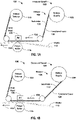
- the printing device has a printing ribbon 102 which follows a ribbon path 104 leading from a ribbon supply spool 106 past a print head 108 and to a ribbon take-up spool 110.
- a printing media 112 follows a media supply path 114 between a platen roller 116 and the print head 108.
- the printing ribbon is supplied from an inwound spool 118, which printing ribbon is sometimes referred to herein as an inwound printing ribbon, meaning that the printing ribbon 102 has a functional layer 120 that faces inward the ribbon supply spool 106, and a substrate 122 that faces outward the spool.
- the print head 108 is configured to transfer ink from the functional layer 120 to the media 112. Accordingly, the printing ribbon 102 is properly oriented, with the functional layer 120 facing the media 112 as both pass between the print head 108 and the platen roller 116.
- Fig. 1B shows the same exemplary printing device 100 of Fig. 1A , except that rather than an inwound spool 118, the printing ribbon 124 is supplied from an outwound spool 126, which printing ribbon is sometimes referred to herein as an outwound printing ribbon, meaning that the printing ribbon 124 has a functional layer 128 that faces inward the ribbon supply spool 130, and a substrate 132 that faces outward the spool.
- the printing ribbon 124 similarly follows the ribbon path 104 leading from the ribbon supply spool 130 past the print head 108 and to a ribbon take-up spool 110.
- the printing media 112 similarly follows the media supply path 114 between the platen roller 116 and the print head 108.
- the outwound spool 126 shown in Fig. 1B provides the printing ribbon 124 properly oriented with the functional layer 128 facing the media 112 as both pass between the print head 108 and the platen roller 116, thereby allowing the print head 108 to transfer ink from the functional layer 128 to the media 112.
- the functional layer of a properly installed printing ribbon faces the media 112, thereby allowing the print head 108 to transfer ink from the functional layer to the media when printing.
- the inwound spool 118 and the outwound spool 126 are installed with opposite orientations relative to one another, such that they rotate in opposite directions relative to one another when unwinding.
- a properly oriented inwound spool 118 rotates counter-clockwise, unwinding from the top
- a properly oriented outwound spool 126 rotates clockwise, unwinding from the bottom.
- the functional layer faces away from the media, which would typically prevent the print head from transferring ink from the functional layer to the media.
- An improperly oriented printing ribbon can be detected by providing a printer equipped with a ribbon sensor in accordance with the present disclosure.
- a ribbon sensor can ascertain an orientation of a printing ribbon when the printing ribbon has a functional layer and a substrate that have at least one property that a ribbon sensor can be configured to detect which differs as between the functional layer and the substrate in at least one respect.
- a response can be triggered when the ribbon sensor detects an improperly oriented printing ribbon and/or an indication can be provided to confirm the proper orientation of a printing ribbon.
- exemplary printers are provided which have a ribbon sensor configured and positioned to ascertain an orientation of the printing ribbon. For example, as shown in Figs.
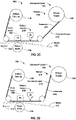
- an exemplary printing device 100 has a ribbon sensor 200 configured and positioned to ascertain an orientation of a printing ribbon. Any suitable configuration and position can be provided. In some embodiments, the ribbon sensor 200 can be positioned at any suitable location along the printing ribbon path 104.
- Fig. 2A shows an exemplary printing device 100 with a properly oriented inwound printing ribbon 202
- Fig. 2B shows the exemplary printing device 100 with an improperly oriented inwound printing ribbon 204
- Fig. 2C shows the exemplary printing device 100 with a properly oriented outwound printing ribbon 210
- Fig. 2D shows the exemplary printing device 100 with an improperly oriented inwound printing ribbon 216.
- the ribbon sensor 200 is located on the substrate-side of a properly oriented printing ribbon.
- the substrate 206/214 faces the ribbon sensor 200.
- the functional layer 208/220 faces the ribbon sensor 200.
- Other configurations also can be provided, several of which are discussed below.
- an exemplary printing device 100 has a properly oriented inwound printing ribbon 202.
- an inwound spool 118 rotates counter-clockwise, unwinding from the top.
- the functional layer 208 faces the media 112 at the platen roller 116
- the substrate 206 faces the ribbon sensor 200 as configured in Fig. 2A .
- a properly oriented inwound printing ribbon 202 can be ascertained when the ribbon sensor 200 as configured in Fig. 2A detects the substrate 206 facing the ribbon sensor.
- the exemplary printing device 100 has an improperly oriented inwound printing ribbon 204.
- the inwound spool 118 rotates in a clockwise direction, unwinding from the bottom.
- the substrate 206 faces the media 112 at the platen roller 116
- the functional layer 208 faces the ribbon sensor 200 as configured in Fig. 2B and opposite the media 112.
- an improperly oriented inwound printing ribbon 204 can be ascertained when the ribbon sensor 200 as configured in Fig. 2B detects the functional layer 208 facing the ribbon sensor.
- a properly oriented outwound printing ribbon 210 rotates in the opposite direction as the properly oriented inwound printing ribbon 202 shown in Fig. 2A .
- Fig. 2C again shows the exemplary printing device 100, but this time with an outwound printing ribbon 210 properly oriented.
- the outwound spool 126 unwinds from the top, rotating counter-clockwise when properly oriented as shown in Fig. 2C .
- the outwound printing ribbon 210 proceeds along the ribbon path 114, similar to the properly oriented inwound printing ribbon, the functional layer 212 of the outwound printing ribbon faces the media 112 at the platen roller 116, and the substrate 214 faces the ribbon sensor 200 as configured in Fig.
- a properly oriented outwound printing ribbon 210 can be ascertained when the ribbon sensor 200 as configured in Fig. 2C detects the substrate 214 facing the ribbon sensor.
- Fig. 2D shows the exemplary printing device 100 with an improperly oriented outwound printing ribbon 216.
- the outwound spool 126 unwinds from the bottom, rotating in a clockwise direction.
- the substrate 214 faces the media 112 at the platen roller 116
- the functional layer 212 faces the ribbon sensor 200 as configured in Fig. 2D .
- an improperly oriented outwound printing ribbon 216 can be ascertained when the ribbon sensor 200 as configured in Fig. 2D detects the functional layer 212 facing the ribbon sensor.
- an exemplary printing device 100 can be configured to identify a printing ribbon from among a plurality of printing ribbons by providing a ribbon sensor in accordance with the present disclosure.
- a ribbon sensor can be configured to identify a printing ribbon from among a plurality of printing ribbons when the printing ribbons among the plurality have at least one property that a ribbon sensor can be configured to detect which differs as among the plurality of printing ribbons.
- a response can be triggered when the ribbon sensor detects the wrong printing ribbon being installed and/or an indication can be provided to confirm the proper printing ribbon is installed.
- a ribbon sensor can be located at any suitable position along a ribbon path 104.
- a ribbon sensor can be located on the substrate-side, and configured such that the ribbon sensor can detect the substrate of a properly oriented printing ribbon.
- a ribbon sensor can be located on the functional layer-side of a properly oriented printing ribbon, such that the ribbon sensor can detect the functional layer of a properly oriented printing ribbon.
- Figs. 3A and 3B show several exemplary ribbon sensor locations and configurations. Fig.
- FIG. 3A shows an exemplary printing device 100, with a properly oriented inwound spool 118, and Fig. 3B shows the exemplary printing device 100 with a properly oriented outwound spool 126. Additional ribbon sensor locations will be apparent to those skilled in the art, all of which are within the spirit and scope of the present disclosure.
- a ribbon sensor can be situated at a location on the substrate-side along a portion of the ribbon path leading to the print head 108, for example at a location between a leading tension roller 300 and a trailing tension roller 302.
- a ribbon sensor may have improved accuracy when located between the tension rollers because tension provided by the tension rollers can help maintain a uniform distance between the printing ribbon and the ribbon sensor.
- areas where a printing ribbon would be expected to have low tension may be less suitable for locating a ribbon sensor because low tension can cause a varying distance between the printing ribbon and the ribbon sensor, leading to decreased accuracy in the values obtained from the ribbon sensor.
- the ribbon sensor 200 shown in Figs. 2A-2D also shown in Figs.
- the ribbon sensor may be situated at a location 304 immediately preceding the print head. Alternatively, the ribbon sensor can be situated at a location following the print head 108 but preceding the trailing tension roller 302 (not shown). In some embodiments, a location following a print head may be less suitable because part of the functional layer of a printing ribbon is removed when printing; however, in some situations this may not be of concern, for example, when sensing a property of the printing ribbon before any of the printing ribbon is used, or when sensing a property of the printing ribbon that would not be affected by some of the printing ribbon having been used.
- the ribbon sensor and the print head can be provided as an integrated component thereby situating the ribbon sensor at a location 304 immediately preceding the print head.
- a ribbon sensor can be provided together with a print head as an integrated component.
- an integrated component 400 includes a print head 108 and a ribbon sensor 402. Such an integrated component can be used, for example, to retrofit prior printing devices with a ribbon sensor.
- an integrated component such as shown in Fig. 4 allows for ideal positioning of a ribbon sensor in small printing devices, for example in which there might not be other space available for a ribbon sensor.
- a ribbon sensor can be situated at a location 306 on the functional layer-side of the printing ribbon, between the leading tension roller 300 and a trailing tension roller 302. In some embodiments, space may be limited on the functional-layer side, particularly as along the media path 114 approaching the impingement of the printing ribbon with the media between the print head 108 and the platen roller 116. In another exemplary embodiment, a ribbon sensor can be situated between the ribbon supply spool 106/130 and the leading tension roller 300, either at a location 308/310 along the substrate-side or at a location 312/314 along the functional layer-side. A comparison of these locations as between Fig.
- 3A and 3B illustrates that in some embodiments, there may exist a differing distance from the printing ribbon and the ribbon sensor as between an inwound spool 118 and an outwound spool 126, because of the differing tangential angles of the printing ribbon leading from the ribbon supply spool 106/130.
- This differing distance can be minimized at a location approaching the leading tension roller 300 in contrast with a location approaching the ribbon supply spool 106/130.
- a ribbon sensor can be situated between the trailing tension roller 302 and the ribbon take-up spool 110, either at a location 316 along the substrate-side or at a location 318 along the functional layer-side.
- a ribbon sensor can be situated at a location 320 along the surface of the ribbon supply spool 106/130 or at a location 322 along the surface of the ribbon take-up spool 110.
- a ribbon sensor will be located at about 1 mm to 10 mm away from the printing ribbon path.
- the distance between a ribbon sensor and a printing ribbon can be 20 mm or closer, 15 mm or closer, 10 mm or closer, 5 m or closer, or 1 mm or closer.
- a functional layer of a printing ribbon will have one or more properties which differ from that of the substrate of the printing ribbon.
- a ribbon sensor can be configured to sense one or more properties of a printing ribbon, and the values obtained from the ribbon sensor can be used to ascertain whether the functional layer or the substrate of the printing ribbon faces the ribbon sensor.
- a ribbon sensor can be configured to sense one or more properties of a printing ribbon, and the values obtained from the ribbon sensor can be used to identify a printing ribbon from among the plurality.
- a thermal transfer printing ribbon may be provided.
- the functional layer of a thermal transfer printing ribbon typically includes a wax, a sensible material (e.g., a coloring agent, dye, pigment, or magnetic particles), and a resin binder.
- the substrate of a thermal transfer printing ribbon is typically a thin film including a synthetic resin, such as polyethylene terephthalate (PET) polyester, and a protective silicone coating deposited on the outward surface of the substrate to reduce friction such as when passing the print head.
- PET polyethylene terephthalate
- Example waxes which can be used in a functional layer include paraffin wax, carnauba wax, and hydrocarbon wax.
- Example resins which can be used in a functional layer include thermoplastic resins and reactive resins such as epoxy resins.
- a sensible material can include a coloring agent, such as a dye or pigment, or magnetic particles.
- Example sensible materials include carbon black and various organic and inorganic pigments and dyes.
- Some functional layers include reactive dyes such as a leuco dye.
- Some functional layers include materials that allow encoding a printing media with a signal inducible ink, such as magnetic pigments or particles, charged pigments or particles, or emissive pigments or particles.
- Other printing ribbons for use in other printing modalities also typically include differing materials as between the functional layer and the substrate.
- a ribbon sensor can be configured to differentiate between a functional layer of a printing ribbon and a substrate of a printing ribbon based on one or more properties that differ as between the materials used in the functional layer and the substrate. Additionally or alternatively, a ribbon sensor can be configured to differentiate between different printing ribbons from among a plurality based on one or more properties that differ as between the materials used and their relative proportions as among the plurality.
- a ribbon sensor can be configured to sense an optical property of a printing ribbon.
- the optical property can be selected based on a difference as between the functional layer and the substrate of the printing ribbon.
- a ribbon sensor can include a reflectance sensor configured to sense the reflectance of a printing ribbon.
- a ribbon sensor can be configured to sense any other optical property, including hue (or components thereof, such as L* a* b* values), lightness, brightness, luminance, emission (such as fluorescence), radiance, transmittance, attenuation, diffraction, refraction, scattering, absorbance, etc.
- a ribbon sensor can be configured to sense any other property of a printing ribbon which may differ as between the functional layer and the substrate of the printing ribbon, or as among a plurality of different printing ribbons, such as an electric property (e.g., electric charge, etc.) or a magnetic property (e.g., magnetic moment, diamagnetism, etc.).
- an electric property e.g., electric charge, etc.
- a magnetic property e.g., magnetic moment, diamagnetism, etc.
- a reflectance sensor typically includes an LED light source such as an infrared LED paired with a photodiode or a phototransistor.
- a ribbon sensor that includes a reflectance sensor can be configured to obtain a signal corresponding to reflection of light from the printing ribbon and incident upon the phototransistor. The signal can be used to ascertain a reflectance value for the surface of the ribbon facing the reflectance sensor, and because typically a substrate and a functional layer of a printing ribbon will exhibit markedly different reflectance values, the values obtained from such as reflectance sensor can be used to ascertain whether the substrate or the functional layer of a printing ribbon faces the ribbon sensor.
- a plurality of printing ribbons can be differentiated from one another using a reflectance sensor to ascertain a reflectance value of a printing ribbon form among the plurality.
- the functional layer of a thermal transfer printing ribbon will typically exhibit a substantially diffuse reflectance and the substrate of a thermal transfer printing ribbon will typically exhibit a substantially specular reflectance.
- a functional layer of a thermal transfer printing ribbon will have a matte appearance and typically a substrate of a thermal transfer printing ribbon will have a gloss appearance.
- printing ribbons for other printing modalities also typically have a functional layer that exhibits a substantially diffuse reflectance and a substrate that exhibits a substantially specular reflectance.
- a reflectance value above a threshold can be characterized as being substantially specular and a reflectance value below the threshold as being substantially diffuse.
- a substantially specular range can be appropriately defined with reflectance values within the range being substantially specular.
- a substantially diffuse range can be appropriately defined with reflectance values within the range being substantially diffuse.
- a functional layer of a printing ribbon can exhibit a substantially diffuse reflectance of at least less than 50% and a substrate of a printing ribbon exhibit a substantially specular reflectance of at least greater than 50%.
- a threshold can be defined at 50%, with reflectance values above the threshold being substantially specular and/or reflectance values below the threshold being substantially diffuse.
- a functional layer of a printing ribbon can exhibit a substantially diffuse reflectance of less than 45%, less than 35%, less than 25%, less than 15%, less than 10%, less than 5%, or less than 1%; and a functional layer of a printing ribbon can exhibit a substantially diffuse reflectance of at least 55%, at least 65%, at least 75%, at least 85%, at least 90%, at least 95%, or at least 99%.
- a threshold can be defined at 45%, 35%, 25%, 15%, 10%, 5%, or 1%, with reflectance values below the threshold being substantially diffuse; and/or a threshold can be defined at 55%, 65%, 75%, 85%, 90%, 95%, or 99%, with reflectance values above the threshold being substantially specular.
- a functional layer of a printing ribbon can exhibit a substantially diffuse reflectance in a range between 55% and 45%, between 45% and 35%, between 35% and 25%, between 25% and 15%, between 15% and 5%, between 10% and 1%, or between 5% and 1%; and/or a functional layer of a printing ribbon can exhibit a substantially diffuse reflectance in a range between 45% and 55%, between 55% and 65%, between 65% and 75%, between 75% and 85%, between 85% and 95%, between 90% and 99%, or between 95% and 99%.
- a range can be defined between 55% and 45%, between 45% and 35%, between 35% and 25%, between 25% and 15%, between 15% and 5%, between 10% and 1%, or between 5% and 1%, with reflectance values within the range being substantially diffuse; and/or a range can be defined between 45% and 55%, between 55% and 65%, between 65% and 75%, between 75% and 85%, between 85% and 95%, between 90% and 99%, or between 95% and 99%, with reflectance values within the range being substantially specular. Similar thresholds or ranges can be provided for any one or more other properties of a printing ribbon, including other optical properties, electric properties, or magnetic properties.
- a reflectance as expected from a substrate of a printing ribbon may differ from a reflectance as expected from a functional layer of a printing ribbon by 1% or more, by 5% or more, by 10% or more, by 20% or more, by 30% or more, by 40%, or more, by 50% or more, by 60% or more, by 70% or more, by 80% or more, or by 90% or more.
- Some printing ribbons may exhibit different reflectance characteristics, however, and those skilled in the art will appreciate that appropriately defined values, thresholds, or ranges can be selected depending on the specific embodiment which those skilled in the art might select from the spirit and scope of the present disclosure.
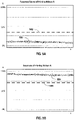
- Figs. 5A through 5F show exemplary optical values corresponding to functional layers and substrates of exemplary printing ribbons.
- the optical values shown in Figs. 5A through 5F can be reflectance values; however, these examples are also intended to be illustrative of examples applicable to other properties.
- Figs. 5A and 5B respectively show exemplary optical values for a functional layer and a substrate of an exemplary printing ribbon.
- Fig. 5A shows an optical value 500 for a functional layer of an exemplary printing ribbon.
- the optical value 500 is below a threshold 502.
- the optical value 500 is a reflectance value, and as being below the threshold 502 can be characterized as a reflectance value corresponding to a substantially diffuse reflectance.
- Fig. 5B shows an optical value 504 for a substrate of an exemplary printing ribbon. The optical value 504 is above a threshold 506.
- the optical value 504 is a reflectance value, and as being above the threshold 506 can be characterized as a reflectance value corresponding to a substantially specular reflectance.
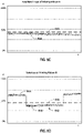
- Figs. 5C and 5D respectively show exemplary optical values, which for example can be reflectance values, for a functional layer and a substrate of another exemplary printing ribbon.
- an optical value 508 is below a threshold 510.
- the optical value 508 is a reflectance value, and the reflectance value can be characterized as corresponding to a substantially diffuse reflectance.
- the optical value 508 might exceed the threshold 502 shown in Fig. 5A ; however, the exemplary embodiment of Fig. 5C provides a different threshold 510, which comparison illustrates that those skilled in the art can select various thresholds as appropriate for the printing ribbon or plurality of printing ribbons of interest.
- FIG. 5D shows an optical value 512 for the substrate of the printing ribbon corresponding to the functional layer shown in Fig. 5C .
- a value can vary, for example, as between a high value 514 and a low value 516.
- a varying optical value may reflect a difference in properties as the printing ribbon moves past the ribbon sensor.
- some substrates may contain information such as indicator marks, text, graphs, or the like, which may exhibit a different optical value than that of the native substrate material.
- a varying optical value may be indicative of a substrate, particularly where a functional layer would not be expected to exhibit such a varying optical value.
- a functional layer may also exhibit a varying optical value.
- a dye sublimation printing ribbon may alternate between colors along the length of the ribbon.
- some printing ribbons may have an alternating series of transfer segments of a coloring agent or ink separated by gaps, which can yield a varying optical value as between the gaps and the transfer segments. As shown in Fig. 5D , the optical value 512 is at times above a threshold 518 and at times below the threshold 518.
- an optical value can be characterized as being below a threshold when the optical value is sometimes below the threshold and/or an optical value can be characterized as being above a threshold when the optical value is sometimes above the threshold.
- the optical value 512 is a reflectance value
- the reflectance value can be characterized as corresponding to a substantially specular reflectance based on the high value 514 being above the threshold 518. This may occur, for example, when surface markings on a substrate have a more diffuse reflectance than the reflectance of the native substrate.
- Figs. 5E and 5F respectively show exemplary optical values for a functional layer and a substrate of yet another exemplary printing ribbon.
- Fig. 5E shows an optical value 520 such as a reflectance value for a functional layer of an exemplary printing ribbon.
- the optical value 520 is within a range 522.
- the optical value 520 is a reflectance value, and as being within the range 522 can be characterized as a reflectance value corresponding to a substantially diffuse reflectance.
- a printer or printing system can be configured to ascertain that a given surface of a printing ribbon faces a ribbon sensor only when the optical values fall within a range.
- a printer or printing system may be configured to ascertain that the optical value 520 corresponds to the functional layer of a printing ribbon only when the optical value falls within the range 522.
- a reflectance value or other optical value corresponding to the functional layer of a printing ribbon or plurality of printing ribbons happens to be known within a certain range.
- even a reflectance value indicating a more diffuse reflectance value outside the range 522 might be characterized as corresponding to the substrate of the printing ribbon rather than to the functional layer.
- a more diffuse reflectance value may correspond to surface markings on a substrate or some other distinguishing feature.
- Fig. 5F shows an optical value 524 such as a reflectance value for a substrate of an exemplary printing ribbon.
- the optical value 524 is outside a range 526.
- the range 526 may be the same as the range 522 shown in Fig. 5E .
- the optical value 524 is a reflectance value, and as being outside the range 526 can be characterized as a reflectance value corresponding to a substantially specular reflectance.
- one or more optical properties or other properties of a printing ribbon can be compared against a combination of defined values, threshold values, and/or ranges.
- a value obtained from a ribbon sensor can be characterized as corresponding to a substrate of a printing ribbon based on the relation of the value to a threshold, and/or as corresponding to a functional layer of the printing ribbon based on the relation of the value to a range, and vice versa.
- a value obtained from a ribbon sensor can be characterized as corresponding to a substrate and/or as corresponding to a functional layer of a printing ribbon, based on a relation of the value to both a threshold and a range.
- one or more optical properties or other properties of a printing ribbon can be compared against a defined value, in addition or as an alternative to a threshold value or a range.
- a defined value can be a known value corresponding to a functional layer of a printing ribbon or a known value corresponding to a substrate of a printing ribbon.
- a printer or printing system may utilize a plurality of different printing ribbons, and the printer or printing system can be configured to identify a printing ribbon from among the plurality based on a value obtained from a ribbon sensor.
- the functional layer and/or the substrate of various printing ribbons may exhibit different values, thereby allowing a printer or printing system to identify a printing ribbon based on the value.
- a printing ribbon can be identified from among a plurality of printing ribbons based on comparison of a value obtained from a ribbon sensor to a threshold value or a range.
- a printer or printing system may use a plurality of printing ribbons, each providing a different coloring agent or ink which may be applied to the media during printing.
- the plurality of printing ribbons may include different colors. Additionally or alternatively, the plurality of printing ribbons may include ribbons with and without certain functional materials, such as reactive dyes, and/or materials that allow encoding a printing media with a signal inducible ink, such as magnetic pigments or particles, charged pigments or particles, or emissive pigments or particles.
- a ribbon sensor may be configured to distinguish between such different printing ribbons based on a comparison of a value obtained from the ribbon sensor to a defined value, threshold value, or range.
- Exemplary methods and features of printing devices and printing systems include methods and features configured for ascertaining an orientation of a printing ribbon, for triggering a response in the event of an improperly oriented printing ribbon, and/or confirming proper orientation of a printing ribbon.
- Exemplary methods and features of printing devices and printing systems additionally or alternatively include methods and features configured for properly installing a printing ribbon.
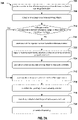
- Fig. 6 shows a flow chart depicting exemplary steps 600 and/or features which can be configured, for example, to ascertain an orientation of a printing ribbon, to provide proper installation of a printing ribbon, to trigger a response in the event of an improperly installed printing ribbon, to confirm proper installation of a printing ribbon, and/or to identify a printing ribbon from among a plurality of printing ribbons.
- the exemplary steps shown in Fig. 6A can be implemented with a ribbon sensor facing the inward surface (i.e., the substrate-side of a properly oriented printing ribbon) 602, and/or with a ribbon sensor facing the outward surface (i.e., the functional layer-side of a properly oriented printing ribbon) 604.
- the ribbon sensor detects a value 606 corresponding to a property of the printing ribbon.
- the property can be any property whereby a functional layer of a printing ribbon can be distinguished from a substrate of the printing ribbon, including an optical property, an electrical property, or a magnetic property as discussed herein.
- the property can additionally or alternatively be any property whereby a printing ribbon can be identified from among a plurality of printing ribbons.
- the value of the property is compared against one or more criteria 608 to confirm whether the value corresponds to the one or more criteria.
- the criteria can be a defined value, a range, and/or a threshold.
- a substrate of a printing ribbon or a plurality of printing ribbons of interest may have a property which corresponds to a defined value, a range, or a threshold.
- a ribbon sensor can be configured to detect the value. The ribbon sensor can detect the value, for example, before starting printing. In some embodiments, a ribbon sensor can be configured to detect the value upon the occurrence of a triggering event.
- a printing device may have a panel or door used to access and replenish a printing ribbon, and closing the panel or door may trigger a switch thereby prompting the ribbon sensor to detect the value.
- the value of the property can be compared against one or more criteria 608 to identify or to confirm the identity of a printing ribbon from among a plurality of printing ribbons.
- a value can be confirmed when the value corresponds to the applicably selected defined value, threshold, or range, for the substrate of the printing ribbon or plurality of printing ribbons of interest.
- a value can be confirmed when the value corresponds to the applicably selected defined value, threshold, or range, for the functional layer of the printing ribbon or plurality of printing ribbons of interest.
- a value detected by the ribbon sensor will not be confirmed when the value does not correspond to the applicably selected defined value, threshold, or range.
- a ribbon sensor obtains a value known to correspond to an improperly oriented printing ribbon, and/or when a ribbon sensor obtains a value from which it remains undetermined whether the printing ribbon is properly oriented.
- a value is confirmed 608 when the printing ribbon is properly oriented 610, and a value is not confirmed when the printing ribbon is improperly oriented and/or when it remains undetermined whether the printing ribbon is improperly oriented.
- the printing device or printing system proceeds with printing 612. Conversely, when the value is not confirmed, a conclusion cannot be made that the printing ribbon is properly oriented, and accordingly in some embodiments a response can be triggered 614.
- the response can include an alarm, such as a visual or audible alarm, and/or an error message provided to a user such as through a user interface on a printing device or through a network configured to remotely alert a user. Additionally, the response may include issuing a stop print command to prevent further printing, re-routing print jobs to a different printing device or printing system, and/or requesting a standby printer.
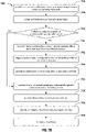
- Figs. 7A through 7C show flow charts depicting additional exemplary embodiments of steps and/or features configured to ascertain an orientation of a printing ribbon, to provide proper installation of a printing ribbon, to trigger a response in the event of an improperly installed printing ribbon and/or to confirm proper installation of a printing ribbon.
- the steps shown in Figs. 7A-7C utilize a ribbon sensor that includes a reflectance sensor configured to sense a reflectance of a printing ribbon and return a reflectance value.
- the steps shown in Figs. 7A-7C can be implemented with a ribbon sensor configured to sense any other property that can be used to distinguish a functional layer of a printing ribbon from a substrate.
- exemplary steps or features 700 can be configured to provide a printer or printing system with a reflectance sensor positioned along a surface of a printing ribbon path 706, and to detect a reflectance value from a printing ribbon 708.
- Exemplary steps or features can be configured to ascertain whether the reflectance value corresponds to a defined reflectance value, range, or threshold for the proper surface of a printing ribbon when the printing ribbon is properly oriented 710, and in turn, to ascertain that the proper surface faces the reflectance sensor 712 when the reflectance value corresponds to the defined reflectance value, range, or threshold and/or to ascertain that the improper surface faces the reflectance sensor 714 when the reflectance value does not corresponds to the defined reflectance value, range, or threshold for the proper surface.
- exemplary steps and/or features can be configured to ascertain that the printing ribbon is properly oriented 716, which may include providing an indication that the printing ribbon is properly oriented 718.
- a printing device or printing system can be configured to proceed with printing 720 upon having ascertained that the proper surface of the printing ribbon faces the reflectance sensor.
- exemplary steps and/or features can be configured to trigger a response which may include providing an indication that the printing ribbon is not properly oriented 724.
- the response or indication may include an alarm, such as a visual or audible alarm, and/or an error message provided to a user such as on a user interface or through a network configured to remotely alert a user. Additionally, the response may include issuing a stop print command to prevent further printing, re-routing print jobs to a different printing device or printing system, and/or requesting a standby printer.
- an alarm such as a visual or audible alarm
- an error message provided to a user such as on a user interface or through a network configured to remotely alert a user.
- the response may include issuing a stop print command to prevent further printing, re-routing print jobs to a different printing device or printing system, and/or requesting a standby printer.
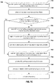
- steps or features 702 can be configured to provide a printer or printing system with a reflectance sensor positioned along an inward surface of a printing ribbon path 726 and to detect a reflectance value from a printing ribbon 728.
- Exemplary steps or features can be configured to ascertain whether the reflectance value corresponds to a substantially specular reflectance 730, and in turn, to ascertain that a first surface of a printing ribbon comprising a substantially specular substrate faces the reflectance sensor 732 when the reflectance value corresponds to a substantially specular reflectance and/or to ascertain that a second surface comprising a substantially diffuse functional layer faces the reflectance sensor 734 when the reflectance value does not corresponds to a substantially specular reflectance.
- the reflectance value can be compared to a defined reflectance value, range, or threshold for a substrate of a printing ribbon or for respective substrates of a plurality of printing ribbons of interest.
- exemplary steps and/or features can be configured to ascertain that the printing ribbon is properly oriented 736, which may include an indication that the printing ribbon is properly oriented 738.
- a printing device or printing system can be configured to proceed with printing 740 upon having ascertained that the printing ribbon is properly oriented such that the substrate of the printing ribbon faces the reflectance sensor.
- exemplary steps and/or features can be configured to trigger a response which may include providing an indication that the printing ribbon is not properly oriented 744.
- the response or indication may include an alarm, such as a visual or audible alarm, and/or an error message provided to a user such as on a user interface or through a network configured to remotely alert a user.
- the response may include issuing a stop print command to prevent further printing, re-routing print jobs to a different printing device or printing system, and/or requesting a standby printer.
- steps or features 704 can be configured to provide a printer or printing system with a reflectance sensor positioned along an outward surface of a printing ribbon path 746 and to detect a reflectance value from a printing ribbon 748.
- Exemplary steps or features can be configured to ascertain whether the reflectance value corresponds to a substantially diffuse reflectance 750, and in turn, to ascertain that a second surface of a printing ribbon comprising a substantially diffuse functional layer faces the reflectance sensor 752 when the reflectance value corresponds to a substantially diffuse reflectance and/or to ascertain that a first surface comprising a substantially specular substrate faces the reflectance sensor 754 when the reflectance value does not corresponds to a substantially diffuse reflectance.
- the reflectance value can be compared to a defined reflectance value, range, or threshold for a functional layer of a printing ribbon or for respective functional layers of a selection of printing ribbons of interest.
- exemplary steps and/or features can be configured to ascertain that the printing ribbon is properly oriented 756, which may include providing an indication that the printing ribbon is properly oriented 758.
- a printing device or printing system can be configured to proceed with printing 760 upon having ascertained that the printing ribbon is properly oriented such that the functional layer of the printing ribbon faces the reflectance sensor.
- exemplary steps and/or features can be configured to trigger a response which may include providing an indication that the printing ribbon is not properly oriented 764.
- the response or indication may include an alarm, such as a visual or audible alarm, and/or an error message provided to a user such as on a user interface or through a network configured to remotely alert a user.
- the response may include issuing a stop print command to prevent further printing, re-routing print jobs to a different printing device or printing system, and/or requesting a standby printer.
- Fig. 8 shows flow charts depicting an exemplary embodiment of steps and/or features configured to identify a printing ribbon from among a plurality of printing ribbons, and to ascertain whether the correct printing ribbon has been installed in the printer.
- the steps shown in Fig. 8 utilize a ribbon sensor that includes a reflectance sensor configured to sense the reflectance of a printing ribbon and return a reflectance value.
- the steps shown in Fig. 8 can be implemented with a ribbon sensor configured to sense any other property that can be used to identify a printing ribbon from among a plurality of printing ribbons.
- Exemplary steps or features 800 can be configured to provide a printer or printing system with a reflectance sensor positioned along a surface of a printing ribbon path 802, and to detect a reflectance value from a printing ribbon 804, and to compare the reflectance value to a defined reflectance value, range, or threshold for each of a plurality of printing ribbons 806 to identify the printing ribbon from among the plurality. Following the comparison, exemplary steps or features can be configured to ascertain whether the printing ribbon has been identified 808, and/or to ascertain whether the correct printing ribbon has been installed in the printer or printing system 810. A response may be triggered 812 upon having identified the printing ribbon and/or upon having ascertained that the correct printing ribbon is installed.
- the response can include providing an indication identifying the printing ribbon and/or an indication that the correct printing ribbon is installed oriented 814. Additionally or alternatively, the response may include executing instructions operable to cause the printer or printing system to proceed with printing according to one or more parameters corresponding to the identified and installed printing ribbon 816.
- the one or more parameters may include print commands, or settings for a print head or other configurable settings of a printer or printing system. For example, the printer or printing system may be configured with different settings depending on the printing ribbon installed. A different response may be triggered upon having ascertained that the incorrect printing ribbon is installed 818, which may include providing an indication that he incorrect printing ribbon is installed 820.
- the response or indication may include an alarm, such as a visual or audible alarm, and/or an error message provided to a user such as on a user interface or through a network configured to remotely alert a user. Additionally, the response may include issuing a stop print command to prevent further printing, re-routing print jobs to a different printing device or printing system, and/or requesting a standby printer.
- an alarm such as a visual or audible alarm
- an error message provided to a user such as on a user interface or through a network configured to remotely alert a user.
- the response may include issuing a stop print command to prevent further printing, re-routing print jobs to a different printing device or printing system, and/or requesting a standby printer.
- Fig. 9 schematically depicts an exemplary network environment 800 within which the devices, systems, and methods disclosed herein can be implemented.
- a network environment can include a plurality of workflow environments 802, 804, 806, each of which including one or more printers or other printing devices 808, 810.
- a server 820 and a memory storage 822 can be provided for managing the network environment 800, which may include managing the devices, systems, and methods disclosed herein at an enterprise level, the workflow environment level, and/or at the device level.
- a signal bearing media include, but are not limited to, the following: recordable type media such as volatile and non-volatile memory devices, floppy and other removable disks, hard disk drives, SSD drives, flash drives, optical discs (e.g., CD ROMs, DVDs, etc.), and computer memory; and transmission type media such as digital and analog communication links using TDM or IP based communication links (e.g., packet links).
- recordable type media such as volatile and non-volatile memory devices, floppy and other removable disks, hard disk drives, SSD drives, flash drives, optical discs (e.g., CD ROMs, DVDs, etc.), and computer memory
- transmission type media such as digital and analog communication links using TDM or IP based communication links (e.g., packet links).
- electrical circuitry includes, but is not limited to, electrical circuitry having at least one discrete electrical circuit, electrical circuitry having at least one integrated circuit, electrical circuitry having at least one application specific integrated circuit, electrical circuitry forming a general purpose computing device configured by a computer program (e.g., a general purpose computer configured by a computer program which at least partially carries out processes and/or devices described herein, or a microprocessor configured by a computer program which at least partially carries out processes and/or devices described herein), electrical circuitry forming a memory device (e.g., forms of random access memory), and/or electrical circuitry forming a communications device (e.g., a modem, communications switch, or optical-electrical equipment).
- a computer program e.g., a general purpose computer configured by a computer program which at least partially carries out processes and/or devices described herein, or a microprocessor configured by a computer program which at least partially carries out processes and/or devices described herein
- electrical circuitry forming a memory device
- a typical data processing system generally includes one or more of a system unit housing, a video display device, a memory such as volatile and non-volatile memory, processors such as microprocessors and digital signal processors, computational entities such as operating systems, drivers, graphical user interfaces, and applications programs, one or more interaction devices, such as a touch pad or screen, and/or control systems including feedback loops and control elements (e.g., feedback for sensing temperature; control heaters for adjusting temperature).
- a typical data processing system may be implemented utilizing any suitable commercially available components, such as those typically found in data computing/communication and/or network computing/communication systems.
- any two components herein combined to achieve a functionality can be seen as “associated with” each other such that the desired functionality is achieved, irrespective of architectures or intermedial components.
- any two components so associated can also be viewed as being “operably connected”, or “operably coupled”, to each other to achieve the desired functionality.
- operably couplable include but are not limited to physically mateable and/or physically interacting components and/or wirelessly interactable and/or wirelessly interacting components and/or logically interacting and/or logically interactable components.
Abstract
Description
- The present disclosure relates to devices, systems, and methods providing a ribbon sensor configured and positioned to ascertain an orientation of a printing ribbon, including devices, systems, and methods configured for detecting an improperly oriented printing ribbon, and for triggering a response in the event of an improperly installed, and/or for confirming proper installation of a printing ribbon.
- There are numerous examples of printers and other printing devices which utilize a printing ribbon to transfer ink to a printing media. A printing ribbon typically includes a substrate, and a functional layer which includes a coloring agent or an ink that is applied to printing media during printing. For example, a thermal transfer printer can use a printing ribbon that has a substrate and a functional layer having a thermally sensitive ink that reacts and transfers from the printing ribbon to the media upon exposure to heat from a print head.
- Printing ribbons are generally removably installed in a printer. As having a finite length, spent printing ribbons need to be replenished with fresh printing ribbons as and when consumed. The task of replenishing a printer with a fresh printing ribbon is typically carried out manually, which introduces the possibility for human error. Thus, sometimes a printing ribbon may be incorrectly installed or improperly oriented in a printer. Additionally, sometimes the wrong printing ribbon might be installed in a printer. Even with an automated system for replenishing a printing ribbon, the possibility for error still exists. Typically, a printing ribbon will be provided as wound upon a spool, with the ribbon unwinding and passing the functional layer facing and in proximity to and between the print head and the printing media during printing. If a printing ribbon happens to be installed with an improper orientation, then the substrate will face the printing media instead of the functional layer, and the printer and printing ribbon will not function as intended to transfer ink from the functional layer to the media. Additionally, a printer and printing ribbon may not function as intended when the printing ribbon installed in the printer happens to be the wrong printing ribbon for the printer or for an intended print job.
- In some situations, it can be difficult to identify the proper orientation for a printing ribbon when installing the printing ribbon in a printer. For example, some users may struggle to distinguish the functional layer from a substrate of a printing ribbon and then remain mindful of which orientation to install the printing ribbon so that the functional layer faces the printing media when properly installed. This can be an issue particularly in environments with poor lighting or where operators are busy. Additionally, sometimes a printing ribbon may have a configuration such that a user cannot see the functional layer in a fresh spool or cartridge. For example, sometimes a printing ribbon can be wound inside a protective wrapper or casing, and/or a leader of ribbon may be provided which does not contain any coloring agent or ink. Moreover, printing ribbons are available as both an inwound spool, meaning the functional layer faces inward the spool, and as an outwound spool, meaning the functional layer faces outward the spool. Additionally, there are numerous different kinds of printing ribbons many of which can look alike. These various combinations and alternatives add compounding sources of error, further increasing the possibility for a printing ribbon to be installed with an improper orientation or for the wrong printing ribbon to be installed in a printer. Even further, sometimes there will exist a nominal level of errors which tend to happen despite all the best intentions.
- The cost associated with even periodic improperly oriented or otherwise incorrectly installed printing ribbons can be significant, especially in high-volume production environments. Sometimes a printer may process print jobs with an improperly oriented or incorrect printing ribbon, resulting in wasted ribbon and printing media. There are also costs associated with downtime and rework resulting from an improperly oriented printing ribbon or an incorrect printing ribbon having been installed. Additionally, in some settings these issues may go unnoticed for quite some time, and/or a user may be unable to quickly respond and correct these issues.
- At least in view of the foregoing issues and shortcomings, there exists a need for improved devices, systems. The present disclosure addresses the foregoing issues and shortcomings, for example, by providing devices, systems, and methods configured for detecting an improperly oriented printing ribbon and/or an incorrect printing ribbon having been installed, including devices, systems, and methods configured to trigger a response in the event of an improperly oriented or incorrect printing ribbon and/or to confirm proper installation of a printing ribbon. Additionally provided are devices, systems, and methods configured to provide proper installation of a printing ribbon and to ascertain an orientation of a printing ribbon and/or to identify a printing ribbon.
- Accordingly, in one aspect, the present disclosure embraces devices, systems, and methods configured for ascertaining an orientation of a printing ribbon and/or identifying a printing ribbon having been installed.
- In an exemplary embodiment, a printer is provided with a printing ribbon installed along a printing ribbon path configured to guide the printing ribbon between a print head and a media. The printer includes a ribbon sensor positioned along the printing ribbon path facing a surface of the printing ribbon. The ribbon sensor can be configured to sense any one or more properties of a printing ribbon, and to ascertain whether a functional layer or a substrate of the printing ribbon faces the ribbon sensor, and/or to identify a printing ribbon from among a plurality. A ribbon sensor can sense any property of the printing ribbon by which the functional layer can be distinguished from the substrate, and/or whereby a printing ribbon can be identified from among a plurality of printing ribbons. For example, a ribbon sensor can be configured to sense an optical property of a printing ribbon, an electrical property of a printing ribbon, and/or a magnetic property of a printing ribbon. A ribbon sensor including an LED light source paired with a photodiode or a phototransistor can be configured to ascertain a reflectance value for a printing ribbon.
- The printing ribbon has a first surface comprising a substantially specular substrate having a first reflectivity and a second surface comprising a substantially diffuse functional layer having a second reflectivity. Typically, the first reflectivity will be greater than the second reflectivity. Exemplary devices, systems, and methods are configured to detect with the ribbon sensor, a reflectance value from the printing ribbon. The reflectance value can be used to ascertain that the first surface faces the ribbon sensor when the reflectance value detected corresponds to a substantially specular reflectance as expected from the first surface, and/or to ascertain that the functional layer faces the ribbon sensor when the reflectance value detected corresponds to a substantially diffuse reflectance as expected from the second surface. The reflectance value can also be used to identify a printing ribbon having been installed in the printer from among a plurality of printing ribbons, based at least in part on the respective printing ribbons from among the plurality exhibiting different reflectance values relative to one another.
- In some embodiments, exemplary devices, systems, and methods can be configured to ascertain, based at least in part on a reflectance value detected with the ribbon sensor, whether the printing ribbon as installed along the printing ribbon path is properly oriented with a first surface facing the print head and a second surface facing the media as intended. Exemplary devices, systems, and methods can be configured to identify a printing ribbon based at least in part on a reflectance value detected with the ribbon sensor. The reflectance value can be compared to a defined value, a threshold, or a range as appropriate for a given embodiment. In some embodiments, a substantially specular reflectance as expected from a substrate of a printing ribbon may differ from a substantially diffuse reflectance as expected from a functional layer by 10% or more. A response can be triggered upon having ascertained, based at least in part on the reflectance value detected, that the printing ribbon as installed along the printing ribbon path is not properly oriented. The response can include an audible alert, a visual alert, a stop print command, re-routing one or more print jobs to a different printer, and/or requesting a standby printer.
- In various embodiments, a printer can be configured such that either the ribbon sensor faces the first surface of a properly oriented printing ribbon or such that the ribbon sensor faces the second surface of a properly oriented printing ribbon. A printing ribbon can be wound upon a spool, which may be an inwound spool, in which the functional surface of the printing ribbon faces inwardly the spool, or and outwound spool, in which the functional surface of the printing ribbon faces outwardly the spool. Exemplary devices, systems, and methods can be configured to provide an indication that the printing ribbon as installed along the printing ribbon path is improperly oriented and/or that the printing ribbon as installed along the printing path is properly oriented. In some embodiments, the printing ribbon can be a thermal transfer ribbon, including a substrate made up of a polyester film, a synthetic resin, and/or a silicone coating, and or including a functional layer made up of a thermoplastic resin, an epoxy resin, a wax, and/or a sensible material including a coloring agent or an ink. The present disclosure also embraces various other kinds of printing ribbons.
- In another embodiment, a printer is provided with a ribbon sensor positioned and configured to face a surface of a printing at least partially installed in the printer. Exemplary devices, systems, and methods can be configured to ascertain that a substrate of the printing ribbon faces the ribbon sensor when the ribbon sensor returns a reflectance value corresponding to a reflectance as expected from a substrate; and/or to ascertain that a thermal transfer layer of the printing ribbon faces the ribbon sensor when the ribbon sensor returns a reflectance value corresponding to a reflectance as expected from a thermal transfer layer. The substrate may have a substantially specular reflectance, and the thermal transfer layer may have a substantially diffuse reflectance. The reflectance as expected from the substrate may differ from the reflectance as expected from the thermal transfer layer by 10% or more. The ribbon sensor may be configured so as to face the substrate when the printing ribbon is properly oriented, or so as to face the thermal transfer layer when the printing ribbon is properly oriented. A response can be triggered when the ribbon sensor returns a reflectance value indicating that that the printing ribbon is improperly oriented. The response can include an audible alert, a visual alert, a stop print command, re-routing one or more print jobs to a different printer, and/or requesting a standby printer.
- In another embodiment, a printer is provided with a print head configured to transfer an ink from a printing ribbon to a media, and with a ribbon sensor configured to detect a reflectance value from the printing ribbon to be utilized by the printer. Exemplary devices, systems, and methods can be configured to detect with the ribbon sensor, a reflectance value from the printing ribbon when at least partially installed in the printer. The printing ribbon has a substrate and a functional layer comprising the ink; and exemplary devices, systems, and methods can be configured to ascertain that the substrate faces the ribbon sensor when the reflectance value corresponds to a substantially specular reflectance, and/or to ascertain that the thermal transfer layer faces the ribbon sensor when the reflectance value corresponds to a substantially diffuse reflectance. In some embodiments, exemplary devices, systems, and methods can be configured to ascertain based at least in part on the reflectance value detected with the ribbon sensor, whether the at least partially installed printing ribbon is properly oriented such that when having commenced printing, the substrate will face the print head and the thermal transfer layer will face the media. The reflectance value corresponding to a substantially specular reflectance can differ from the reflectance value corresponding to a substantially diffuse reflectance by 10% or more. In some embodiments, a ribbon sensor can be configured to identify a printing ribbon from among a plurality of printing ribbons based at least in part on a reflectance value.
- In some embodiments, the ribbon sensor faces the substrate when the printing ribbon is properly oriented. An indication can be provided, indicating that the printing ribbon is improperly oriented when having ascertained that the thermal transfer layer improperly faces the ribbon sensor. Additionally or alternatively, an indication can be provided, indicating that the printing ribbon is properly oriented when having ascertained that the substrate properly faces the ribbon sensor. A response can be triggered upon having ascertained, based at least in part on the reflectance value detected with the ribbon sensor, that the at least partially installed printing ribbon is not properly oriented. The response can include an audible alert, a visual alert, a stop print command, re-routing one or more print jobs to a different printer, and/or requesting a standby printer.
- The foregoing summary is illustrative only, and is not intended to be in any way limiting. In addition to the illustrative features and embodiments described above, further aspects, features, and embodiments will become apparent by references to the drawings, the following detailed description, and the claims.
-
-
Figure 1A schematically depicts an exemplary printing device with an inwound printing ribbon properly installed. -
Figure 1B schematically depicts an exemplary printing device with an outwound printing ribbon properly installed. -
Figure 2A schematically depicts an exemplary printing device with a ribbon sensor configured to ascertain an orientation of a printing ribbon, with a properly oriented inwound printing ribbon. -
Figure 2B schematically depicts an exemplary printing device with a ribbon sensor configured to ascertain an orientation of a printing ribbon, with an improperly oriented inwound printing ribbon. -
Figure 2C schematically depicts an exemplary printing device with a ribbon sensor configured to ascertain an orientation of a printing ribbon, with a properly oriented outwound printing ribbon. -
Figure 2D schematically depicts an exemplary printing device with a ribbon sensor configured to ascertain an orientation of a printing ribbon, with an improperly oriented outwound printing ribbon. -
Figures 3A and3B schematically depict exemplary locations for a ribbon sensor, respectively showing a properly oriented inwound printing ribbon and a properly oriented outwound printing ribbon. -
Figure 4 schematically depicts an exemplary embodiment of an integrated component including a print head and a ribbon sensor. -
Figures 5A through 5F graphically depict exemplary optical values corresponding to respective functional layers and substrates of exemplary printing ribbons. -
Figure 6 shows a flow chart depicting exemplary steps and/or features configured, among other things, to ascertain an orientation of a printing ribbon. -
Figures 7A through 7C show flow charts depicting additional exemplary steps and/or features configured, among other things, to ascertain an orientation of a printing ribbon. -
Figure 8 shows a flow chart depicting exemplary steps and/or features configured, among other things, to identify a printing ribbon from among a plurality of printing ribbons. -
Figure 9 schematically depicts an exemplary network environment for implementing the devices, systems, and methods disclosed herein. - In the following detailed description, various aspects and features are described in greater detail with reference to the accompanying figures, including among other aspects and features, exemplary devices, systems, and methods configured to ascertain an orientation of a printing ribbon, to provide proper installation of a printing ribbon, to trigger a response in the event of an improperly installed printing ribbon and/or to confirm proper installation of a printing ribbon. Additionally described are exemplary devices, systems, and methods configured to identify a printing ribbon from among a plurality of printing ribbons. Numerous specific details are set forth in order to provide a thorough understanding of the present disclosure. It will be apparent, however, to one skilled in the art that the presently disclosed devices, systems, and methods may be performed without some or all of these specific details. In other instances, well known aspects have not been described in detail in order not to unnecessarily obscure the present disclosure. The following detailed description is therefore not to be taken in a limiting sense, and it is intended that other embodiments are within the spirit and scope of the present disclosure.
- There are numerous examples of printers and other printing devices which utilize a printing ribbon to transfer a coloring agent or ink to a printing media, some of which are discussed herein. There are also numerous examples of printing ribbons, some of which are discussed herein. A printing ribbon typically includes a substrate, and a functional layer which includes a coloring agent or ink that is applied to printing media during printing. For example, a thermal transfer printer uses a printing ribbon that typically has a substrate, and a functional layer or thermal transfer layer having a thermally sensitive ink that reacts and transfers from the printing ribbon to the media upon exposure to heat from a print head. A dye-sublimation printer uses a similarly configured printing ribbon. Additional exemplary printing ribbons include fabric printing ribbons that contain a liquid ink, and impact printing ribbons for use with impact printers such as dot-matrix printers or typewriters. In some embodiments, a printing ribbon can be transported in parallel with the media. Alternatively, a printing ribbon can be transported perpendicular to the media. Some exemplary printer configurations and printing ribbons and are discussed in further detail below. While the present disclosure discusses only an exemplary selection of the possible kinds of printers and printing ribbons, those skilled in the art will appreciate that numerous other kinds of printers and printing ribbons can be configured in accordance with the devices, systems, and methods disclosed herein, all of which are within the spirit and scope of the present disclosure.
- In accordance with the present disclosure, printing devices and printing systems are provided which have a ribbon sensor positioned along the printing ribbon path and configured to ascertain an orientation of the printing ribbon and/or to identify a printing ribbon from among a plurality.
Figs. 1A and 1B schematically depict an exemplary printing device. In some embodiments, the exemplary printing device can be a thermal transfer printer. Alternatively, the printing device can be a dye-sublimation printer or any other kind of printing device that uses a printing ribbon. As shown inFig. 1A , anexemplary printing device 100 is provided. The printing device has aprinting ribbon 102 which follows aribbon path 104 leading from aribbon supply spool 106 past aprint head 108 and to a ribbon take-upspool 110. Aprinting media 112 follows amedia supply path 114 between aplaten roller 116 and theprint head 108. As shown inFig. 1A , the printing ribbon is supplied from aninwound spool 118, which printing ribbon is sometimes referred to herein as an inwound printing ribbon, meaning that theprinting ribbon 102 has afunctional layer 120 that faces inward theribbon supply spool 106, and asubstrate 122 that faces outward the spool. Theprint head 108 is configured to transfer ink from thefunctional layer 120 to themedia 112. Accordingly, theprinting ribbon 102 is properly oriented, with thefunctional layer 120 facing themedia 112 as both pass between theprint head 108 and theplaten roller 116. -
Fig. 1B shows the sameexemplary printing device 100 ofFig. 1A , except that rather than aninwound spool 118, theprinting ribbon 124 is supplied from anoutwound spool 126, which printing ribbon is sometimes referred to herein as an outwound printing ribbon, meaning that theprinting ribbon 124 has afunctional layer 128 that faces inward theribbon supply spool 130, and asubstrate 132 that faces outward the spool. Theprinting ribbon 124 similarly follows theribbon path 104 leading from theribbon supply spool 130 past theprint head 108 and to a ribbon take-upspool 110. Theprinting media 112 similarly follows themedia supply path 114 between theplaten roller 116 and theprint head 108. As with the inwound spool inFig. 1A , theoutwound spool 126 shown inFig. 1B provides theprinting ribbon 124 properly oriented with thefunctional layer 128 facing themedia 112 as both pass between theprint head 108 and theplaten roller 116, thereby allowing theprint head 108 to transfer ink from thefunctional layer 128 to themedia 112. - Thus, as shown in
Figs. 1A and 1B , the functional layer of a properly installed printing ribbon faces themedia 112, thereby allowing theprint head 108 to transfer ink from the functional layer to the media when printing. Theinwound spool 118 and theoutwound spool 126 are installed with opposite orientations relative to one another, such that they rotate in opposite directions relative to one another when unwinding. With the configuration of theexemplary printing device 100 shown inFigs. 1A and 1B , a properly orientedinwound spool 118 rotates counter-clockwise, unwinding from the top, and a properly orientedoutwound spool 126 rotates clockwise, unwinding from the bottom. Conversely, with an improperly oriented printing ribbon the functional layer faces away from the media, which would typically prevent the print head from transferring ink from the functional layer to the media. - An improperly oriented printing ribbon can be detected by providing a printer equipped with a ribbon sensor in accordance with the present disclosure. As discussed in more detail below, a ribbon sensor can ascertain an orientation of a printing ribbon when the printing ribbon has a functional layer and a substrate that have at least one property that a ribbon sensor can be configured to detect which differs as between the functional layer and the substrate in at least one respect. A response can be triggered when the ribbon sensor detects an improperly oriented printing ribbon and/or an indication can be provided to confirm the proper orientation of a printing ribbon. Accordingly, exemplary printers are provided which have a ribbon sensor configured and positioned to ascertain an orientation of the printing ribbon. For example, as shown in
Figs. 2A-2D , anexemplary printing device 100 has aribbon sensor 200 configured and positioned to ascertain an orientation of a printing ribbon. Any suitable configuration and position can be provided. In some embodiments, theribbon sensor 200 can be positioned at any suitable location along theprinting ribbon path 104. -
Fig. 2A shows anexemplary printing device 100 with a properly orientedinwound printing ribbon 202, andFig. 2B shows theexemplary printing device 100 with an improperly orientedinwound printing ribbon 204. Conversely,Fig. 2C shows theexemplary printing device 100 with a properly orientedoutwound printing ribbon 210, andFig. 2D shows theexemplary printing device 100 with an improperly oriented inwound printing ribbon 216. As shown inFigs. 2A-2D , theribbon sensor 200 is located on the substrate-side of a properly oriented printing ribbon. Thus, with a properly orientedprinting ribbon 202/210 in the configuration shown inFigs. 2A and2C , thesubstrate 206/214 faces theribbon sensor 200. Conversely, with an improperly orientedprinting ribbon 204/216 in the configuration shown inFigs. 2B and2D , the functional layer 208/220 faces theribbon sensor 200. Other configurations also can be provided, several of which are discussed below. - As shown in
Fig. 2A anexemplary printing device 100 has a properly orientedinwound printing ribbon 202. When properly oriented, aninwound spool 118 rotates counter-clockwise, unwinding from the top. As theinwound printing ribbon 202 proceeds along theribbon path 114, the functional layer 208 faces themedia 112 at theplaten roller 116, and thesubstrate 206 faces theribbon sensor 200 as configured inFig. 2A . Thus, a properly orientedinwound printing ribbon 202 can be ascertained when theribbon sensor 200 as configured inFig. 2A detects thesubstrate 206 facing the ribbon sensor. By contrast, as shown inFig. 2B theexemplary printing device 100 has an improperly orientedinwound printing ribbon 204. When improperly oriented, theinwound spool 118 rotates in a clockwise direction, unwinding from the bottom. As the improperly oriented inwound printing ribbon proceeds along theribbon path 114, thesubstrate 206 faces themedia 112 at theplaten roller 116, and the functional layer 208 faces theribbon sensor 200 as configured inFig. 2B and opposite themedia 112. Thus, an improperly orientedinwound printing ribbon 204 can be ascertained when theribbon sensor 200 as configured inFig. 2B detects the functional layer 208 facing the ribbon sensor. - Conversely, as shown in
Fig. 2C , a properly orientedoutwound printing ribbon 210 rotates in the opposite direction as the properly orientedinwound printing ribbon 202 shown inFig. 2A . Here,Fig. 2C again shows theexemplary printing device 100, but this time with anoutwound printing ribbon 210 properly oriented. Theoutwound spool 126 unwinds from the top, rotating counter-clockwise when properly oriented as shown inFig. 2C . As theoutwound printing ribbon 210 proceeds along theribbon path 114, similar to the properly oriented inwound printing ribbon, thefunctional layer 212 of the outwound printing ribbon faces themedia 112 at theplaten roller 116, and thesubstrate 214 faces theribbon sensor 200 as configured inFig. 2C . Thus, a properly orientedoutwound printing ribbon 210 can be ascertained when theribbon sensor 200 as configured inFig. 2C detects thesubstrate 214 facing the ribbon sensor. By contrast,Fig. 2D shows theexemplary printing device 100 with an improperly oriented outwound printing ribbon 216. Theoutwound spool 126 unwinds from the bottom, rotating in a clockwise direction. As the outwound printing ribbon proceeds along theribbon path 114, thesubstrate 214 faces themedia 112 at theplaten roller 116, and thefunctional layer 212 faces theribbon sensor 200 as configured inFig. 2D . Thus, an improperly oriented outwound printing ribbon 216 can be ascertained when theribbon sensor 200 as configured inFig. 2D detects thefunctional layer 212 facing the ribbon sensor. - In some embodiments, an
exemplary printing device 100 can be configured to identify a printing ribbon from among a plurality of printing ribbons by providing a ribbon sensor in accordance with the present disclosure. As discussed in more detail below, a ribbon sensor can be configured to identify a printing ribbon from among a plurality of printing ribbons when the printing ribbons among the plurality have at least one property that a ribbon sensor can be configured to detect which differs as among the plurality of printing ribbons. A response can be triggered when the ribbon sensor detects the wrong printing ribbon being installed and/or an indication can be provided to confirm the proper printing ribbon is installed. - In addition to the ribbon sensor location shown in
Figs. 2A-2D , a ribbon sensor can be located at any suitable position along aribbon path 104. Thus, other configurations also can be provided, several of which are discussed below. In an exemplary embodiment, a ribbon sensor can be located on the substrate-side, and configured such that the ribbon sensor can detect the substrate of a properly oriented printing ribbon. Alternatively, a ribbon sensor can be located on the functional layer-side of a properly oriented printing ribbon, such that the ribbon sensor can detect the functional layer of a properly oriented printing ribbon. As examples,Figs. 3A and3B show several exemplary ribbon sensor locations and configurations.Fig. 3A shows anexemplary printing device 100, with a properly orientedinwound spool 118, andFig. 3B shows theexemplary printing device 100 with a properly orientedoutwound spool 126. Additional ribbon sensor locations will be apparent to those skilled in the art, all of which are within the spirit and scope of the present disclosure. - As shown in
Figs. 3A and3B , in some embodiments a ribbon sensor can be situated at a location on the substrate-side along a portion of the ribbon path leading to theprint head 108, for example at a location between a leadingtension roller 300 and a trailingtension roller 302. A ribbon sensor may have improved accuracy when located between the tension rollers because tension provided by the tension rollers can help maintain a uniform distance between the printing ribbon and the ribbon sensor. Conversely, areas where a printing ribbon would be expected to have low tension may be less suitable for locating a ribbon sensor because low tension can cause a varying distance between the printing ribbon and the ribbon sensor, leading to decreased accuracy in the values obtained from the ribbon sensor. Theribbon sensor 200 shown inFigs. 2A-2D (also shown inFigs. 3A and3B ) provides one example of a ribbon sensor located between tension rollers. Any location between thetension rollers 300/302 may be suitable in various embodiments. The ribbon sensor may be situated at alocation 304 immediately preceding the print head. Alternatively, the ribbon sensor can be situated at a location following theprint head 108 but preceding the trailing tension roller 302 (not shown). In some embodiments, a location following a print head may be less suitable because part of the functional layer of a printing ribbon is removed when printing; however, in some situations this may not be of concern, for example, when sensing a property of the printing ribbon before any of the printing ribbon is used, or when sensing a property of the printing ribbon that would not be affected by some of the printing ribbon having been used. In some embodiments, the ribbon sensor and the print head can be provided as an integrated component thereby situating the ribbon sensor at alocation 304 immediately preceding the print head. One example of this configuration is shown with theribbon sensor 200 as located in the exemplary embodiments ofFigs. 2A and2C . As another example, a ribbon sensor can be provided together with a print head as an integrated component. As shown inFig. 4 , anintegrated component 400 includes aprint head 108 and aribbon sensor 402. Such an integrated component can be used, for example, to retrofit prior printing devices with a ribbon sensor. Additionally, an integrated component such as shown inFig. 4 allows for ideal positioning of a ribbon sensor in small printing devices, for example in which there might not be other space available for a ribbon sensor. - Further referring to
Figs. 3A and3B , a ribbon sensor can be situated at alocation 306 on the functional layer-side of the printing ribbon, between the leadingtension roller 300 and a trailingtension roller 302. In some embodiments, space may be limited on the functional-layer side, particularly as along themedia path 114 approaching the impingement of the printing ribbon with the media between theprint head 108 and theplaten roller 116. In another exemplary embodiment, a ribbon sensor can be situated between theribbon supply spool 106/130 and the leadingtension roller 300, either at alocation 308/310 along the substrate-side or at alocation 312/314 along the functional layer-side. A comparison of these locations as betweenFig. 3A and3B illustrates that in some embodiments, there may exist a differing distance from the printing ribbon and the ribbon sensor as between aninwound spool 118 and anoutwound spool 126, because of the differing tangential angles of the printing ribbon leading from theribbon supply spool 106/130. This differing distance can be minimized at a location approaching the leadingtension roller 300 in contrast with a location approaching theribbon supply spool 106/130. In another exemplary embodiment, a ribbon sensor can be situated between the trailingtension roller 302 and the ribbon take-upspool 110, either at alocation 316 along the substrate-side or at alocation 318 along the functional layer-side. In another exemplary embodiment, a ribbon sensor can be situated at alocation 320 along the surface of theribbon supply spool 106/130 or at alocation 322 along the surface of the ribbon take-upspool 110. Typically, a ribbon sensor will be located at about 1 mm to 10 mm away from the printing ribbon path. In some embodiments, the distance between a ribbon sensor and a printing ribbon can be 20 mm or closer, 15 mm or closer, 10 mm or closer, 5 m or closer, or 1 mm or closer. - In general, a functional layer of a printing ribbon will have one or more properties which differ from that of the substrate of the printing ribbon. Given this, a ribbon sensor can be configured to sense one or more properties of a printing ribbon, and the values obtained from the ribbon sensor can be used to ascertain whether the functional layer or the substrate of the printing ribbon faces the ribbon sensor. Additionally, when a plurality of printing ribbons has one or more properties that differ as among the plurality, a ribbon sensor can be configured to sense one or more properties of a printing ribbon, and the values obtained from the ribbon sensor can be used to identify a printing ribbon from among the plurality.
- In an exemplary embodiment, a thermal transfer printing ribbon may be provided. The functional layer of a thermal transfer printing ribbon typically includes a wax, a sensible material (e.g., a coloring agent, dye, pigment, or magnetic particles), and a resin binder. By contrast, the substrate of a thermal transfer printing ribbon is typically a thin film including a synthetic resin, such as polyethylene terephthalate (PET) polyester, and a protective silicone coating deposited on the outward surface of the substrate to reduce friction such as when passing the print head. Example waxes which can be used in a functional layer include paraffin wax, carnauba wax, and hydrocarbon wax. Example resins which can be used in a functional layer include thermoplastic resins and reactive resins such as epoxy resins. A sensible material can include a coloring agent, such as a dye or pigment, or magnetic particles. Example sensible materials include carbon black and various organic and inorganic pigments and dyes. Some functional layers include reactive dyes such as a leuco dye. Some functional layers include materials that allow encoding a printing media with a signal inducible ink, such as magnetic pigments or particles, charged pigments or particles, or emissive pigments or particles. Other printing ribbons for use in other printing modalities also typically include differing materials as between the functional layer and the substrate. A ribbon sensor can be configured to differentiate between a functional layer of a printing ribbon and a substrate of a printing ribbon based on one or more properties that differ as between the materials used in the functional layer and the substrate. Additionally or alternatively, a ribbon sensor can be configured to differentiate between different printing ribbons from among a plurality based on one or more properties that differ as between the materials used and their relative proportions as among the plurality.
- In an exemplary embodiment, a ribbon sensor can be configured to sense an optical property of a printing ribbon. The optical property can be selected based on a difference as between the functional layer and the substrate of the printing ribbon. For example, a ribbon sensor can include a reflectance sensor configured to sense the reflectance of a printing ribbon. Additionally or alternatively, a ribbon sensor can be configured to sense any other optical property, including hue (or components thereof, such as L* a* b* values), lightness, brightness, luminance, emission (such as fluorescence), radiance, transmittance, attenuation, diffraction, refraction, scattering, absorbance, etc. In various other embodiments, a ribbon sensor can be configured to sense any other property of a printing ribbon which may differ as between the functional layer and the substrate of the printing ribbon, or as among a plurality of different printing ribbons, such as an electric property (e.g., electric charge, etc.) or a magnetic property (e.g., magnetic moment, diamagnetism, etc.).
- Sensors for measuring various optical or other properties are well known to those skilled in the art and therefore will not be discussed in detail. As a general example, a reflectance sensor typically includes an LED light source such as an infrared LED paired with a photodiode or a phototransistor. A ribbon sensor that includes a reflectance sensor can be configured to obtain a signal corresponding to reflection of light from the printing ribbon and incident upon the phototransistor. The signal can be used to ascertain a reflectance value for the surface of the ribbon facing the reflectance sensor, and because typically a substrate and a functional layer of a printing ribbon will exhibit markedly different reflectance values, the values obtained from such as reflectance sensor can be used to ascertain whether the substrate or the functional layer of a printing ribbon faces the ribbon sensor. Similarly, a plurality of printing ribbons can be differentiated from one another using a reflectance sensor to ascertain a reflectance value of a printing ribbon form among the plurality.
- Given the materials typically used in a thermal transfer printing ribbon such as those discussed above, the functional layer of a thermal transfer printing ribbon will typically exhibit a substantially diffuse reflectance and the substrate of a thermal transfer printing ribbon will typically exhibit a substantially specular reflectance. In other words, typically a functional layer of a thermal transfer printing ribbon will have a matte appearance and typically a substrate of a thermal transfer printing ribbon will have a gloss appearance. Similarly, printing ribbons for other printing modalities also typically have a functional layer that exhibits a substantially diffuse reflectance and a substrate that exhibits a substantially specular reflectance.
- In an exemplary embodiment, a reflectance value above a threshold can be characterized as being substantially specular and a reflectance value below the threshold as being substantially diffuse. Similarly, in another exemplary embodiment a substantially specular range can be appropriately defined with reflectance values within the range being substantially specular. Likewise, a substantially diffuse range can be appropriately defined with reflectance values within the range being substantially diffuse. As examples, in some embodiments, a functional layer of a printing ribbon can exhibit a substantially diffuse reflectance of at least less than 50% and a substrate of a printing ribbon exhibit a substantially specular reflectance of at least greater than 50%. Accordingly, a threshold can be defined at 50%, with reflectance values above the threshold being substantially specular and/or reflectance values below the threshold being substantially diffuse. In other embodiments, as examples, a functional layer of a printing ribbon can exhibit a substantially diffuse reflectance of less than 45%, less than 35%, less than 25%, less than 15%, less than 10%, less than 5%, or less than 1%; and a functional layer of a printing ribbon can exhibit a substantially diffuse reflectance of at least 55%, at least 65%, at least 75%, at least 85%, at least 90%, at least 95%, or at least 99%. Accordingly, as examples, a threshold can be defined at 45%, 35%, 25%, 15%, 10%, 5%, or 1%, with reflectance values below the threshold being substantially diffuse; and/or a threshold can be defined at 55%, 65%, 75%, 85%, 90%, 95%, or 99%, with reflectance values above the threshold being substantially specular.
- In another exemplary embodiment, as examples, a functional layer of a printing ribbon can exhibit a substantially diffuse reflectance in a range between 55% and 45%, between 45% and 35%, between 35% and 25%, between 25% and 15%, between 15% and 5%, between 10% and 1%, or between 5% and 1%; and/or a functional layer of a printing ribbon can exhibit a substantially diffuse reflectance in a range between 45% and 55%, between 55% and 65%, between 65% and 75%, between 75% and 85%, between 85% and 95%, between 90% and 99%, or between 95% and 99%. Accordingly, as examples, a range can be defined between 55% and 45%, between 45% and 35%, between 35% and 25%, between 25% and 15%, between 15% and 5%, between 10% and 1%, or between 5% and 1%, with reflectance values within the range being substantially diffuse; and/or a range can be defined between 45% and 55%, between 55% and 65%, between 65% and 75%, between 75% and 85%, between 85% and 95%, between 90% and 99%, or between 95% and 99%, with reflectance values within the range being substantially specular. Similar thresholds or ranges can be provided for any one or more other properties of a printing ribbon, including other optical properties, electric properties, or magnetic properties.
- In another exemplary embodiment, as examples, a reflectance as expected from a substrate of a printing ribbon may differ from a reflectance as expected from a functional layer of a printing ribbon by 1% or more, by 5% or more, by 10% or more, by 20% or more, by 30% or more, by 40%, or more, by 50% or more, by 60% or more, by 70% or more, by 80% or more, or by 90% or more. Some printing ribbons may exhibit different reflectance characteristics, however, and those skilled in the art will appreciate that appropriately defined values, thresholds, or ranges can be selected depending on the specific embodiment which those skilled in the art might select from the spirit and scope of the present disclosure.
- As further examples,
Figs. 5A through 5F show exemplary optical values corresponding to functional layers and substrates of exemplary printing ribbons. For example, the optical values shown inFigs. 5A through 5F can be reflectance values; however, these examples are also intended to be illustrative of examples applicable to other properties. Accordingly, in an exemplary embodiment,Figs. 5A and 5B respectively show exemplary optical values for a functional layer and a substrate of an exemplary printing ribbon.Fig. 5A shows anoptical value 500 for a functional layer of an exemplary printing ribbon. Theoptical value 500 is below athreshold 502. In an exemplary embodiment, theoptical value 500 is a reflectance value, and as being below thethreshold 502 can be characterized as a reflectance value corresponding to a substantially diffuse reflectance.Fig. 5B shows anoptical value 504 for a substrate of an exemplary printing ribbon. Theoptical value 504 is above athreshold 506. In an exemplary embodiment, theoptical value 504 is a reflectance value, and as being above thethreshold 506 can be characterized as a reflectance value corresponding to a substantially specular reflectance. -
Figs. 5C and 5D respectively show exemplary optical values, which for example can be reflectance values, for a functional layer and a substrate of another exemplary printing ribbon. As shown inFig. 5C , anoptical value 508 is below athreshold 510. In an exemplary embodiment, theoptical value 508 is a reflectance value, and the reflectance value can be characterized as corresponding to a substantially diffuse reflectance. By comparison, theoptical value 508 might exceed thethreshold 502 shown inFig. 5A ; however, the exemplary embodiment ofFig. 5C provides adifferent threshold 510, which comparison illustrates that those skilled in the art can select various thresholds as appropriate for the printing ribbon or plurality of printing ribbons of interest.Fig. 5D shows anoptical value 512 for the substrate of the printing ribbon corresponding to the functional layer shown inFig. 5C . As illustrated by theoptical value 512, a value can vary, for example, as between ahigh value 514 and alow value 516. In some embodiments, a varying optical value may reflect a difference in properties as the printing ribbon moves past the ribbon sensor. For example, some substrates may contain information such as indicator marks, text, graphs, or the like, which may exhibit a different optical value than that of the native substrate material. - In some embodiments, a varying optical value may be indicative of a substrate, particularly where a functional layer would not be expected to exhibit such a varying optical value. However, in some embodiments a functional layer may also exhibit a varying optical value. For example, a dye sublimation printing ribbon may alternate between colors along the length of the ribbon. As another example, some printing ribbons may have an alternating series of transfer segments of a coloring agent or ink separated by gaps, which can yield a varying optical value as between the gaps and the transfer segments. As shown in
Fig. 5D , theoptical value 512 is at times above athreshold 518 and at times below thethreshold 518. In some embodiments, an optical value can be characterized as being below a threshold when the optical value is sometimes below the threshold and/or an optical value can be characterized as being above a threshold when the optical value is sometimes above the threshold. For example, when theoptical value 512 is a reflectance value, in some embodiments the reflectance value can be characterized as corresponding to a substantially specular reflectance based on thehigh value 514 being above thethreshold 518. This may occur, for example, when surface markings on a substrate have a more diffuse reflectance than the reflectance of the native substrate. -
Figs. 5E and 5F respectively show exemplary optical values for a functional layer and a substrate of yet another exemplary printing ribbon.Fig. 5E shows anoptical value 520 such as a reflectance value for a functional layer of an exemplary printing ribbon. Theoptical value 520 is within arange 522. In an exemplary embodiment, theoptical value 520 is a reflectance value, and as being within therange 522 can be characterized as a reflectance value corresponding to a substantially diffuse reflectance. In some embodiments, a printer or printing system can be configured to ascertain that a given surface of a printing ribbon faces a ribbon sensor only when the optical values fall within a range. For example, a printer or printing system may be configured to ascertain that theoptical value 520 corresponds to the functional layer of a printing ribbon only when the optical value falls within therange 522. This may be appropriate where a reflectance value or other optical value corresponding to the functional layer of a printing ribbon or plurality of printing ribbons happens to be known within a certain range. In some embodiments, even a reflectance value indicating a more diffuse reflectance value outside therange 522 might be characterized as corresponding to the substrate of the printing ribbon rather than to the functional layer. Here, a more diffuse reflectance value may correspond to surface markings on a substrate or some other distinguishing feature.Fig. 5F shows anoptical value 524 such as a reflectance value for a substrate of an exemplary printing ribbon. Theoptical value 524 is outside arange 526. In some embodiments, therange 526 may be the same as therange 522 shown inFig. 5E . In an exemplary embodiment, theoptical value 524 is a reflectance value, and as being outside therange 526 can be characterized as a reflectance value corresponding to a substantially specular reflectance. - In some embodiments, one or more optical properties or other properties of a printing ribbon can be compared against a combination of defined values, threshold values, and/or ranges. For example, a value obtained from a ribbon sensor can be characterized as corresponding to a substrate of a printing ribbon based on the relation of the value to a threshold, and/or as corresponding to a functional layer of the printing ribbon based on the relation of the value to a range, and vice versa. As another example, a value obtained from a ribbon sensor can be characterized as corresponding to a substrate and/or as corresponding to a functional layer of a printing ribbon, based on a relation of the value to both a threshold and a range. In some embodiments, one or more optical properties or other properties of a printing ribbon can be compared against a defined value, in addition or as an alternative to a threshold value or a range. For example, a defined value can be a known value corresponding to a functional layer of a printing ribbon or a known value corresponding to a substrate of a printing ribbon.
- In some embodiments, a printer or printing system may utilize a plurality of different printing ribbons, and the printer or printing system can be configured to identify a printing ribbon from among the plurality based on a value obtained from a ribbon sensor. For example, the functional layer and/or the substrate of various printing ribbons may exhibit different values, thereby allowing a printer or printing system to identify a printing ribbon based on the value. Similarly, in some embodiments a printing ribbon can be identified from among a plurality of printing ribbons based on comparison of a value obtained from a ribbon sensor to a threshold value or a range. In some embodiments, a printer or printing system may use a plurality of printing ribbons, each providing a different coloring agent or ink which may be applied to the media during printing. For example, the plurality of printing ribbons may include different colors. Additionally or alternatively, the plurality of printing ribbons may include ribbons with and without certain functional materials, such as reactive dyes, and/or materials that allow encoding a printing media with a signal inducible ink, such as magnetic pigments or particles, charged pigments or particles, or emissive pigments or particles. A ribbon sensor may be configured to distinguish between such different printing ribbons based on a comparison of a value obtained from the ribbon sensor to a defined value, threshold value, or range.
- Exemplary methods and features of printing devices and printing systems include methods and features configured for ascertaining an orientation of a printing ribbon, for triggering a response in the event of an improperly oriented printing ribbon, and/or confirming proper orientation of a printing ribbon. Exemplary methods and features of printing devices and printing systems additionally or alternatively include methods and features configured for properly installing a printing ribbon.
-
Fig. 6 shows a flow chart depictingexemplary steps 600 and/or features which can be configured, for example, to ascertain an orientation of a printing ribbon, to provide proper installation of a printing ribbon, to trigger a response in the event of an improperly installed printing ribbon, to confirm proper installation of a printing ribbon, and/or to identify a printing ribbon from among a plurality of printing ribbons. The exemplary steps shown in Fig. 6A can be implemented with a ribbon sensor facing the inward surface (i.e., the substrate-side of a properly oriented printing ribbon) 602, and/or with a ribbon sensor facing the outward surface (i.e., the functional layer-side of a properly oriented printing ribbon) 604. With a printing ribbon at least partially installed in a printer or printing system, the ribbon sensor detects avalue 606 corresponding to a property of the printing ribbon. The property can be any property whereby a functional layer of a printing ribbon can be distinguished from a substrate of the printing ribbon, including an optical property, an electrical property, or a magnetic property as discussed herein. The property can additionally or alternatively be any property whereby a printing ribbon can be identified from among a plurality of printing ribbons. - The value of the property is compared against one or
more criteria 608 to confirm whether the value corresponds to the one or more criteria. As examples, the criteria can be a defined value, a range, and/or a threshold. For example, a substrate of a printing ribbon or a plurality of printing ribbons of interest may have a property which corresponds to a defined value, a range, or a threshold. A ribbon sensor can be configured to detect the value. The ribbon sensor can detect the value, for example, before starting printing. In some embodiments, a ribbon sensor can be configured to detect the value upon the occurrence of a triggering event. For example, a printing device may have a panel or door used to access and replenish a printing ribbon, and closing the panel or door may trigger a switch thereby prompting the ribbon sensor to detect the value. Additionally or alternatively, the value of the property can be compared against one ormore criteria 608 to identify or to confirm the identity of a printing ribbon from among a plurality of printing ribbons. - When a ribbon sensor faces the inward surface of a properly oriented
printing ribbon 602, a value can be confirmed when the value corresponds to the applicably selected defined value, threshold, or range, for the substrate of the printing ribbon or plurality of printing ribbons of interest. Conversely, when the ribbon sensor faces the outward surface of a properly orientedprinting ribbon 604, a value can be confirmed when the value corresponds to the applicably selected defined value, threshold, or range, for the functional layer of the printing ribbon or plurality of printing ribbons of interest. In some embodiments, a value detected by the ribbon sensor will not be confirmed when the value does not correspond to the applicably selected defined value, threshold, or range. This may occur, for example, when a ribbon sensor obtains a value known to correspond to an improperly oriented printing ribbon, and/or when a ribbon sensor obtains a value from which it remains undetermined whether the printing ribbon is properly oriented. In some embodiments, a value is confirmed 608 when the printing ribbon is properly oriented 610, and a value is not confirmed when the printing ribbon is improperly oriented and/or when it remains undetermined whether the printing ribbon is improperly oriented. - With the printing ribbon properly oriented 610, the printing device or printing system proceeds with
printing 612. Conversely, when the value is not confirmed, a conclusion cannot be made that the printing ribbon is properly oriented, and accordingly in some embodiments a response can be triggered 614. The response can include an alarm, such as a visual or audible alarm, and/or an error message provided to a user such as through a user interface on a printing device or through a network configured to remotely alert a user. Additionally, the response may include issuing a stop print command to prevent further printing, re-routing print jobs to a different printing device or printing system, and/or requesting a standby printer. -
Figs. 7A through 7C show flow charts depicting additional exemplary embodiments of steps and/or features configured to ascertain an orientation of a printing ribbon, to provide proper installation of a printing ribbon, to trigger a response in the event of an improperly installed printing ribbon and/or to confirm proper installation of a printing ribbon. In an exemplary embodiment, the steps shown inFigs. 7A-7C utilize a ribbon sensor that includes a reflectance sensor configured to sense a reflectance of a printing ribbon and return a reflectance value. In other exemplary embodiments, the steps shown inFigs. 7A-7C can be implemented with a ribbon sensor configured to sense any other property that can be used to distinguish a functional layer of a printing ribbon from a substrate. - With reference to
Fig. 7A , exemplary steps or features 700 can be configured to provide a printer or printing system with a reflectance sensor positioned along a surface of aprinting ribbon path 706, and to detect a reflectance value from aprinting ribbon 708. Exemplary steps or features can be configured to ascertain whether the reflectance value corresponds to a defined reflectance value, range, or threshold for the proper surface of a printing ribbon when the printing ribbon is properly oriented 710, and in turn, to ascertain that the proper surface faces thereflectance sensor 712 when the reflectance value corresponds to the defined reflectance value, range, or threshold and/or to ascertain that the improper surface faces thereflectance sensor 714 when the reflectance value does not corresponds to the defined reflectance value, range, or threshold for the proper surface. Upon having ascertained that the proper surface of the printing ribbon faces thereflectance sensor 712, exemplary steps and/or features can be configured to ascertain that the printing ribbon is properly oriented 716, which may include providing an indication that the printing ribbon is properly oriented 718. A printing device or printing system can be configured to proceed withprinting 720 upon having ascertained that the proper surface of the printing ribbon faces the reflectance sensor. Conversely, upon having ascertained that the printing ribbon is not properly oriented 722, exemplary steps and/or features can be configured to trigger a response which may include providing an indication that the printing ribbon is not properly oriented 724. The response or indication may include an alarm, such as a visual or audible alarm, and/or an error message provided to a user such as on a user interface or through a network configured to remotely alert a user. Additionally, the response may include issuing a stop print command to prevent further printing, re-routing print jobs to a different printing device or printing system, and/or requesting a standby printer. - In another exemplary embodiment shown in
Fig. 7B , steps or features 702 can be configured to provide a printer or printing system with a reflectance sensor positioned along an inward surface of aprinting ribbon path 726 and to detect a reflectance value from aprinting ribbon 728. Exemplary steps or features can be configured to ascertain whether the reflectance value corresponds to a substantiallyspecular reflectance 730, and in turn, to ascertain that a first surface of a printing ribbon comprising a substantially specular substrate faces thereflectance sensor 732 when the reflectance value corresponds to a substantially specular reflectance and/or to ascertain that a second surface comprising a substantially diffuse functional layer faces thereflectance sensor 734 when the reflectance value does not corresponds to a substantially specular reflectance. The reflectance value can be compared to a defined reflectance value, range, or threshold for a substrate of a printing ribbon or for respective substrates of a plurality of printing ribbons of interest. Upon having ascertained that the substrate of the printing ribbon faces thereflectance sensor 732, exemplary steps and/or features can be configured to ascertain that the printing ribbon is properly oriented 736, which may include an indication that the printing ribbon is properly oriented 738. A printing device or printing system can be configured to proceed withprinting 740 upon having ascertained that the printing ribbon is properly oriented such that the substrate of the printing ribbon faces the reflectance sensor. Conversely, upon having ascertained that the printing ribbon is not properly oriented 742, exemplary steps and/or features can be configured to trigger a response which may include providing an indication that the printing ribbon is not properly oriented 744. The response or indication may include an alarm, such as a visual or audible alarm, and/or an error message provided to a user such as on a user interface or through a network configured to remotely alert a user. Additionally, the response may include issuing a stop print command to prevent further printing, re-routing print jobs to a different printing device or printing system, and/or requesting a standby printer. - In yet another exemplary embodiment shown in
Fig. 7C , steps or features 704 can be configured to provide a printer or printing system with a reflectance sensor positioned along an outward surface of aprinting ribbon path 746 and to detect a reflectance value from aprinting ribbon 748. Exemplary steps or features can be configured to ascertain whether the reflectance value corresponds to a substantially diffusereflectance 750, and in turn, to ascertain that a second surface of a printing ribbon comprising a substantially diffuse functional layer faces thereflectance sensor 752 when the reflectance value corresponds to a substantially diffuse reflectance and/or to ascertain that a first surface comprising a substantially specular substrate faces thereflectance sensor 754 when the reflectance value does not corresponds to a substantially diffuse reflectance. The reflectance value can be compared to a defined reflectance value, range, or threshold for a functional layer of a printing ribbon or for respective functional layers of a selection of printing ribbons of interest. Upon having ascertained that the functional layer of the printing ribbon faces thereflectance sensor 752, exemplary steps and/or features can be configured to ascertain that the printing ribbon is properly oriented 756, which may include providing an indication that the printing ribbon is properly oriented 758. A printing device or printing system can be configured to proceed withprinting 760 upon having ascertained that the printing ribbon is properly oriented such that the functional layer of the printing ribbon faces the reflectance sensor. Conversely, upon having ascertained that the printing ribbon is not properly oriented 762, exemplary steps and/or features can be configured to trigger a response which may include providing an indication that the printing ribbon is not properly oriented 764. The response or indication may include an alarm, such as a visual or audible alarm, and/or an error message provided to a user such as on a user interface or through a network configured to remotely alert a user. Additionally, the response may include issuing a stop print command to prevent further printing, re-routing print jobs to a different printing device or printing system, and/or requesting a standby printer. -
Fig. 8 shows flow charts depicting an exemplary embodiment of steps and/or features configured to identify a printing ribbon from among a plurality of printing ribbons, and to ascertain whether the correct printing ribbon has been installed in the printer. In an exemplary embodiment, the steps shown inFig. 8 utilize a ribbon sensor that includes a reflectance sensor configured to sense the reflectance of a printing ribbon and return a reflectance value. In other exemplary embodiments, the steps shown inFig. 8 can be implemented with a ribbon sensor configured to sense any other property that can be used to identify a printing ribbon from among a plurality of printing ribbons. Exemplary steps or features 800 can be configured to provide a printer or printing system with a reflectance sensor positioned along a surface of aprinting ribbon path 802, and to detect a reflectance value from aprinting ribbon 804, and to compare the reflectance value to a defined reflectance value, range, or threshold for each of a plurality ofprinting ribbons 806 to identify the printing ribbon from among the plurality. Following the comparison, exemplary steps or features can be configured to ascertain whether the printing ribbon has been identified 808, and/or to ascertain whether the correct printing ribbon has been installed in the printer orprinting system 810. A response may be triggered 812 upon having identified the printing ribbon and/or upon having ascertained that the correct printing ribbon is installed. The response can include providing an indication identifying the printing ribbon and/or an indication that the correct printing ribbon is installed oriented 814. Additionally or alternatively, the response may include executing instructions operable to cause the printer or printing system to proceed with printing according to one or more parameters corresponding to the identified and installedprinting ribbon 816. The one or more parameters may include print commands, or settings for a print head or other configurable settings of a printer or printing system. For example, the printer or printing system may be configured with different settings depending on the printing ribbon installed. A different response may be triggered upon having ascertained that the incorrect printing ribbon is installed 818, which may include providing an indication that he incorrect printing ribbon is installed 820. The response or indication may include an alarm, such as a visual or audible alarm, and/or an error message provided to a user such as on a user interface or through a network configured to remotely alert a user. Additionally, the response may include issuing a stop print command to prevent further printing, re-routing print jobs to a different printing device or printing system, and/or requesting a standby printer. -
Fig. 9 schematically depicts anexemplary network environment 800 within which the devices, systems, and methods disclosed herein can be implemented. In some embodiments, a network environment can include a plurality ofworkflow environments other printing devices server 820 and amemory storage 822 can be provided for managing thenetwork environment 800, which may include managing the devices, systems, and methods disclosed herein at an enterprise level, the workflow environment level, and/or at the device level. - The foregoing detailed description and accompanying figures set forth typical embodiments of the devices, systems, and methods presently disclosed. The present disclosure is not limited to such exemplary embodiments. It will be apparent that numerous other devices, systems, and methods may be provided in accordance with the present disclosure. The present disclosure may utilize any variety of aspects, features, or steps, or combinations thereof which may be within the contemplation of those skilled in the art.
- Various embodiments have been set forth via the use of block diagrams, flowcharts, and/or examples. Insofar as such block diagrams, flowcharts, and/or examples contain one or more functions and/or operations, it will be understood by those skilled in the art that each function and/or operation within such block diagrams, flowcharts, or examples can be implemented, individually and/or collectively, by a wide range of hardware, software, firmware, or virtually any combination thereof. In one embodiment, several portions of the subject matter described herein may be implemented via Application Specific Integrated Circuits (ASICs), Field Programmable Gate Arrays (FPGAs), digital signal processors (DSPs), or other integrated formats. However, those skilled in the art will recognize that some aspects and/or features of the embodiments disclosed herein, in whole or in part, can be equivalently implemented in integrated circuits, as one or more computer programs running on one or more computers (e.g., as one or more programs running on one or more computer systems), as one or more programs running on one or more processors (e.g., as one or more programs running on one or more microprocessors), as firmware, or as virtually any combination thereof, and that designing the circuitry and/or writing the code for the software and or firmware would be well within the skill of one of ordinary skill in the art in light of the present disclosure.
- In addition, those skilled in the art will appreciate that some mechanisms of the subject matter described herein are capable of being distributed as a program product in a variety of forms, and that an illustrative embodiment of the subject matter described herein applies equally regardless of the signal bearing media used to carry out the distribution. Examples of a signal bearing media include, but are not limited to, the following: recordable type media such as volatile and non-volatile memory devices, floppy and other removable disks, hard disk drives, SSD drives, flash drives, optical discs (e.g., CD ROMs, DVDs, etc.), and computer memory; and transmission type media such as digital and analog communication links using TDM or IP based communication links (e.g., packet links).
- In a general sense, those skilled in the art will recognize that the various aspects described herein which can be implemented, individually and/or collectively, by a wide range of hardware, software, firmware, or any combination thereof can be viewed as being composed of various types of "electrical circuitry." Consequently, as used herein "electrical circuitry" includes, but is not limited to, electrical circuitry having at least one discrete electrical circuit, electrical circuitry having at least one integrated circuit, electrical circuitry having at least one application specific integrated circuit, electrical circuitry forming a general purpose computing device configured by a computer program (e.g., a general purpose computer configured by a computer program which at least partially carries out processes and/or devices described herein, or a microprocessor configured by a computer program which at least partially carries out processes and/or devices described herein), electrical circuitry forming a memory device (e.g., forms of random access memory), and/or electrical circuitry forming a communications device (e.g., a modem, communications switch, or optical-electrical equipment).
- Those skilled in the art will recognize that it is common within the art to describe devices and/or processes in the fashion set forth herein, and thereafter use engineering practices to integrate such described devices and/or processes into data processing systems. That is, at least a portion of the devices and/or processes described herein can be integrated into a data processing system via a reasonable amount of experimentation. Those having skill in the art will recognize that a typical data processing system generally includes one or more of a system unit housing, a video display device, a memory such as volatile and non-volatile memory, processors such as microprocessors and digital signal processors, computational entities such as operating systems, drivers, graphical user interfaces, and applications programs, one or more interaction devices, such as a touch pad or screen, and/or control systems including feedback loops and control elements (e.g., feedback for sensing temperature; control heaters for adjusting temperature). A typical data processing system may be implemented utilizing any suitable commercially available components, such as those typically found in data computing/communication and/or network computing/communication systems.
- The foregoing described aspects depict different components contained within, or connected with, different other components. It is to be understood that such depicted architectures are merely exemplary, and that in fact many other architectures can be implemented which achieve the same functionality. In a conceptual sense, any arrangement of components to achieve the same functionality is effectively "associated" such that the desired functionality is achieved. Hence, any two components herein combined to achieve a functionality can be seen as "associated with" each other such that the desired functionality is achieved, irrespective of architectures or intermedial components. Likewise, any two components so associated can also be viewed as being "operably connected", or "operably coupled", to each other to achieve the desired functionality. Specific examples of operably couplable include but are not limited to physically mateable and/or physically interacting components and/or wirelessly interactable and/or wirelessly interacting components and/or logically interacting and/or logically interactable components.
- The use of the term "and/or" includes any and all combinations of one or more of the associated listed items. The figures are schematic representations and so are not necessarily drawn to scale. Unless otherwise noted, specific terms have been used in a generic and descriptive sense and not for purposes of limitation.
- While various aspects, features, and embodiments have been disclosed herein, other aspects, features, and embodiments will be apparent to those skilled in the art. The various aspects, features, and embodiments disclosed herein are for purposes of illustration and are not intended to be limiting. It is intended that the scope of the present invention be defined by the following claims and their equivalents:
-
-
Statement 1. A printing system comprising:- a print head in association with a platen roller for printing;
- a media configured to follow a media supply path which passes between said platen roller and said print head;
- a ribbon, comprising a substrate layer and a thermal transfer layer comprising ink, configured to follow a ribbon path which passes between said print head and said platen roller;
- a ribbon sensor, positioned so as to face a surface of the ribbon and configured to detect a reflectance value from a ribbon to be utilized by the printing system;
- wherein the printing system is configured to ascertain that the substrate layer faces the ribbon sensor when the reflectance value corresponds to a substantially specular reflectance, and/or to ascertain that the thermal transfer layer faces the ribbon sensor when the reflectance value corresponds to a substantially diffuse reflectance.
-
Statement 2. The printing system ofStatement 1, wherein the ribbon sensor is positioned to face the substrate layer when the ribbon is properly oriented. -
Statement 3. The printing system ofStatement 1, wherein the ribbon sensor is positioned to face the thermal transfer layer when the ribbon is properly oriented. - Statement 4. The printing system of
Statement 1, wherein the ribbon sensor is triggered upon closing a door or panel, wherein said door panel is to access and replenish a ribbon of the printing system. - Statement 5. The printing system of
Statement 1, wherein the said ascertaining is based on the reflectance from the substrate layer differing from the reflectance the thermal transfer layer by 10% or more. - Statement 6. The printing system of
Statement 1, wherein the printing system is configured to ascertain, based on reflectance value detected by the ribbon sensor, whether or not the printing ribbon is properly oriented with the substrate layer facing the print head and the thermal transfer layer facing the media. - Statement 7. The printing system of Statement 6, wherein the printing system is configured to trigger a response when the ribbon is not properly oriented, the response comprising one or more of: an audible alert, a visual alert, a stop print command, re-routing one or more print jobs to a different printing system, and/or requesting a standby printing system.
- Statement 8. The printing system of
Statement 1, wherein the printing system is configured such that either the ribbon sensor faces the substrate layer of a properly oriented printing ribbon or such that the ribbon sensor faces the thermal transfer layer of a properly oriented printing ribbon. - Statement 9. The printing system of
Statement 1, wherein the printing system is configured to:- ascertain that the thermal transfer layer of the printing ribbon faces the ribbon sensor when the ribbon sensor returns a reflectance below a threshold; and/or
- ascertain that the substrate layer of the printing ribbon faces the ribbon sensor when the ribbon sensor returns a reflectance above a threshold.
- Statement 10. A method comprising:
- providing a printer comprising a print head configured to transfer an ink from a printing ribbon to a media, the printer comprising a ribbon sensor configured to detect a reflectance value from a printing ribbon to be utilized by the printer;
- detecting with the ribbon sensor, a reflectance value from a printing ribbon having been at least partially installed in the printer, wherein the printing ribbon comprises a substrate and a thermal transfer layer comprising the ink;
- ascertaining that the substrate faces the ribbon sensor when the reflectance value corresponds to a substantially specular reflectance, and/or ascertaining that the thermal transfer layer faces the ribbon sensor when the reflectance value corresponds to a substantially diffuse reflectance;
- triggering a response upon having ascertained, based at least in part on the reflectance value detected with the ribbon sensor, that the at least partially installed printing ribbon is not properly oriented.
- Statement 11. The method of Statement 10, comprising ascertaining, based at least in part on the reflectance value detected with the ribbon sensor, whether or not the at least partially installed printing ribbon is properly oriented such that when having commenced printing, the substrate will face the print head and the thermal transfer layer will face the media.
- Statement 12. The method of Statement 10, wherein the response comprises of one or more of: an audible alert, a visual alert, a stop print command, re-routing one or more print jobs to a different printer, and/or requesting a standby printer.
- Statement 13. The method of Statement 10, wherein the ribbon sensor faces the substrate when the printing ribbon is properly oriented, and wherein the method further comprises:
- providing an indication that the printing ribbon is improperly oriented when having ascertained that the thermal transfer layer faces the ribbon sensor; and/or
- providing an indication that the printing ribbon is properly oriented when having ascertained that the substrate faces the ribbon sensor.
- Statement 14. The method of Statement 10, wherein said ascertaining is based at least in part on the reflectance value corresponding to a substantially specular reflectance differing from the reflectance value corresponding to a substantially diffuse reflectance by 10% or more.
- Statement 15. The method of Statement 10, comprising:
- ascertaining that the thermal transfer layer of the printing ribbon faces the ribbon sensor when the ribbon sensor returns a reflectance below a threshold; and/or
- ascertaining that the substrate of the printing ribbon faces the ribbon sensor when the ribbon sensor returns a reflectance above a threshold.
Claims (15)
- A device comprising:a print head in association with a platen roller for printing;a media configured to follow a media supply path between the said platen roller and the print head;a ribbon comprising a first surface comprising a substantially specular substrate having a first reflectivity and a second surface comprising a substantially diffuse functional layer having a second reflectivity, the first reflectance being greater than the second reflectivity;a ribbon supply spool and a ribbon take-up spool configured to supply the said ribbon along a ribbon supply path leading from the ribbon supply spool past the print head and to the ribbon take-up spool; anda ribbon sensor, positioned so as to face a surface of the printing ribbon and configured to detect a reflectance value from a printing ribbon to be utilized by the device;wherein the device is configured to ascertain that the first surface faces the ribbon sensor when the reflectance value detected corresponds to a substantially specular reflectance as expected from the first surface, and/or the second surface faces the ribbon sensor when the reflectance value detected corresponds to a substantially diffuse reflectance as expected from the second surface.
- The device of claim 1, wherein the ribbon sensor is positioned to face the first surface when the ribbon is properly oriented.
- The device of claim 1, wherein the device is configured to ascertain, based on reflectance value detected by the ribbon sensor, whether or not the ribbon is properly oriented with the first surface facing the print head and the second surface facing the media.
- The device of claim 1, wherein the device is configured to trigger a response when ribbon is not oriented properly, the response comprising one or more of: an audible alert, a visual alert, a stop print command, re-routing one or more print jobs to a different device, and/or requesting a standby device.
- The device of claim 1, wherein the device is configured:ascertain that the second surface of the ribbon faces the ribbon sensor when the ribbon sensor returns a reflectance below a threshold; and/orascertain that the first surface of the ribbon faces the ribbon sensor when the ribbon sensor returns a reflectance above a threshold.
- The device of claim 1, wherein the ribbon sensor is triggered upon closing a door or panel, wherein said door panel is to access and replenish the ribbon.
- A method of ascertaining an orientation of a printing ribbon from among a plurality of printing ribbons, the method comprising:providing a printer comprising a print head, a printing ribbon having been installed along a printing ribbon path configured to guide the printing ribbon between the print head and a media, and a ribbon sensor positioned along the printing ribbon path facing a surface of the printing ribbon;wherein the printing ribbon has a first surface comprising a substantially specular substrate having a first reflectivity and a second surface comprising a substantially diffuse functional layer having a second reflectivity, the first reflectivity being greater than the second reflectivity;detecting with the ribbon sensor, a reflectance value from the printing ribbon; andascertaining that the first surface faces the ribbon sensor when the reflectance value detected corresponds to a substantially specular reflectance as expected from the first surface, and/or ascertaining that the functional layer faces the ribbon sensor when the reflectance value detected corresponds to a substantially diffuse reflectance as expected from the second surface;detecting the printing ribbon from among a plurality of printing ribbon based on at least one property that the ribbon sensor can be configured to detect which differs as among the plurality of printing ribbons;triggering a response when the ribbon sensor detects wrong printing ribbon installed.
- The method of claim 7, wherein the printing ribbon is wound upon a spool; and
wherein the method further comprises ascertaining whether the printing ribbon having been installed along the printing ribbon path has the functional surface facing inwardly or outwardly on the spool. - The method of claim 7, wherein the printing ribbon comprises a thermal transfer layer, and wherein the first surface comprises a polyester film, a synthetic resin, and/or a silicone coating.
- The method of claim 7, wherein said ascertaining is based at least in part on the substantially specular reflectance as expected from the first surface differing from the substantially diffuse reflectance as expected from the second surface by 10% or more.
- The method of claim 7, wherein the second surface comprises a thermoplastic resin, an epoxy resin, a wax, and/or a coloring agent.
- The method of claim 7, wherein the ribbon sensor is triggered upon closing a door or panel, wherein said door panel is to access and replenish the ribbon.
- The method of claim 7, further comprising ascertaining, based at least in part on the reflectance value detected with the ribbon sensor, whether or not the printing ribbon is properly oriented such that when having commenced printing, the substantially specular substrate faces the print head and the thermal transfer layer faces the media.
- The method of claim 7, wherein the ribbon sensor faces the substantially specular substrate when the printing ribbon is properly oriented, and wherein the method further comprises:providing an indication that the printing ribbon is improperly oriented when having ascertained that the thermal transfer layer faces the ribbon sensor; and/orproviding an indication that the printing ribbon is properly oriented when having ascertained that the substrate faces the ribbon sensor.
- The method of claim 7, further comprising:ascertaining that the thermal transfer layer of the printing ribbon faces the ribbon sensor when the ribbon sensor returns a reflectance below a threshold; andascertaining that the substrate of the printing ribbon faces the ribbon sensor when the ribbon sensor returns a reflectance above a threshold.
Applications Claiming Priority (4)
| Application Number | Priority Date | Filing Date | Title |
|---|---|---|---|
| US15/416,606 US9849691B1 (en) | 2017-01-26 | 2017-01-26 | Detecting printing ribbon orientation |
| US15/802,714 US10350905B2 (en) | 2017-01-26 | 2017-11-03 | Detecting printing ribbon orientation |
| EP20179586.1A EP3760447B1 (en) | 2017-01-26 | 2018-01-23 | Detecting printing ribbon orientation |
| EP18153104.7A EP3354474B1 (en) | 2017-01-26 | 2018-01-23 | Detecting printing ribbon orientation |
Related Parent Applications (3)
| Application Number | Title | Priority Date | Filing Date |
|---|---|---|---|
| EP18153104.7A Division EP3354474B1 (en) | 2017-01-26 | 2018-01-23 | Detecting printing ribbon orientation |
| EP20179586.1A Division-Into EP3760447B1 (en) | 2017-01-26 | 2018-01-23 | Detecting printing ribbon orientation |
| EP20179586.1A Division EP3760447B1 (en) | 2017-01-26 | 2018-01-23 | Detecting printing ribbon orientation |
Publications (1)
| Publication Number | Publication Date |
|---|---|
| EP4049849A1 true EP4049849A1 (en) | 2022-08-31 |
Family
ID=61024617
Family Applications (3)
| Application Number | Title | Priority Date | Filing Date |
|---|---|---|---|
| EP22160711.2A Pending EP4049849A1 (en) | 2017-01-26 | 2018-01-23 | Detecting printing ribbon orientation |
| EP20179586.1A Active EP3760447B1 (en) | 2017-01-26 | 2018-01-23 | Detecting printing ribbon orientation |
| EP18153104.7A Active EP3354474B1 (en) | 2017-01-26 | 2018-01-23 | Detecting printing ribbon orientation |
Family Applications After (2)
| Application Number | Title | Priority Date | Filing Date |
|---|---|---|---|
| EP20179586.1A Active EP3760447B1 (en) | 2017-01-26 | 2018-01-23 | Detecting printing ribbon orientation |
| EP18153104.7A Active EP3354474B1 (en) | 2017-01-26 | 2018-01-23 | Detecting printing ribbon orientation |
Country Status (3)
| Country | Link |
|---|---|
| US (1) | US10350905B2 (en) |
| EP (3) | EP4049849A1 (en) |
| CN (2) | CN113619297B (en) |
Citations (4)
| Publication number | Priority date | Publication date | Assignee | Title |
|---|---|---|---|---|
| WO2001032427A1 (en) * | 1999-10-29 | 2001-05-10 | Hewlett-Packard Company | Advanced media determination system for inkjet printing |
| US20050079298A1 (en) * | 2003-10-09 | 2005-04-14 | Keeton Mark E. | Thermal transfer ribbon with end of ribbon markers |
| WO2013025746A1 (en) * | 2011-08-15 | 2013-02-21 | Videojet Technologies Inc. | Thermal transfer printer |
| US20160325556A1 (en) * | 2014-09-26 | 2016-11-10 | JVC Kenwood Corporation | Image forming apparatus, retransfer printer, and image forming method |
Family Cites Families (541)
| Publication number | Priority date | Publication date | Assignee | Title |
|---|---|---|---|---|
| FR2622146A1 (en) * | 1987-10-26 | 1989-04-28 | Duport Jean Claude | COMPOSITE RIBBON FOR LABEL PRINTING MACHINES AND MACHINE USING SUCH A RIBBON |
| US5127751A (en) | 1989-11-30 | 1992-07-07 | Sharp Kabushiki Kaisha | Printing apparatus with improved work of ink ribbon replacement |
| DE4332609A1 (en) | 1993-09-24 | 1995-03-30 | Esselte Meto Int Gmbh | Circuit arrangement for data input and output for a printer |
| US7387253B1 (en) | 1996-09-03 | 2008-06-17 | Hand Held Products, Inc. | Optical reader system comprising local host processor and optical reader |
| US5777652A (en) * | 1994-05-13 | 1998-07-07 | Alps Electric Co., Ltd. | Thermal transfer printer |
| JP3330476B2 (en) | 1995-10-18 | 2002-09-30 | 株式会社 沖情報システムズ | Adapter case and ticket processing device using the adapter case for mounting ink ribbon |
| JPH09202027A (en) * | 1996-01-25 | 1997-08-05 | Nec Eng Ltd | Ink ribbon discriminating device |
| US5755519A (en) * | 1996-12-04 | 1998-05-26 | Fargo Electronics, Inc. | Printer ribbon identification sensor |
| US7304670B1 (en) | 1997-03-28 | 2007-12-04 | Hand Held Products, Inc. | Method and apparatus for compensating for fixed pattern noise in an imaging system |
| JP2000085223A (en) * | 1998-09-14 | 2000-03-28 | Casio Comput Co Ltd | Printing device and storage medium |
| JP2001063195A (en) * | 1999-08-25 | 2001-03-13 | Alps Electric Co Ltd | Thermal transfer printer |
| US6832725B2 (en) | 1999-10-04 | 2004-12-21 | Hand Held Products, Inc. | Optical reader comprising multiple color illumination |
| US7270274B2 (en) | 1999-10-04 | 2007-09-18 | Hand Held Products, Inc. | Imaging module comprising support post for optical reader |
| US20090134221A1 (en) | 2000-11-24 | 2009-05-28 | Xiaoxun Zhu | Tunnel-type digital imaging-based system for use in automated self-checkout and cashier-assisted checkout operations in retail store environments |
| US7708205B2 (en) | 2003-11-13 | 2010-05-04 | Metrologic Instruments, Inc. | Digital image capture and processing system employing multi-layer software-based system architecture permitting modification and/or extension of system features and functions by way of third party code plug-ins |
| US7128266B2 (en) | 2003-11-13 | 2006-10-31 | Metrologic Instruments. Inc. | Hand-supportable digital imaging-based bar code symbol reader supporting narrow-area and wide-area modes of illumination and image capture |
| US8682077B1 (en) | 2000-11-28 | 2014-03-25 | Hand Held Products, Inc. | Method for omnidirectional processing of 2D images including recognizable characters |
| EP1354291B1 (en) | 2001-01-22 | 2006-08-02 | Hand Held Products, Inc. | Optical reader having partial frame operating mode |
| US7268924B2 (en) | 2001-01-22 | 2007-09-11 | Hand Held Products, Inc. | Optical reader having reduced parameter determination delay |
| US7376234B1 (en) | 2001-05-14 | 2008-05-20 | Hand Held Products, Inc. | Portable keying device and method |
| US7111787B2 (en) | 2001-05-15 | 2006-09-26 | Hand Held Products, Inc. | Multimode image capturing and decoding optical reader |
| US6834807B2 (en) | 2001-07-13 | 2004-12-28 | Hand Held Products, Inc. | Optical reader having a color imager |
| US7748620B2 (en) | 2002-01-11 | 2010-07-06 | Hand Held Products, Inc. | Transaction terminal including imaging module |
| US6959865B2 (en) | 2002-03-28 | 2005-11-01 | Hand Held Products, Inc. | Customizable optical reader |
| US7086596B2 (en) | 2003-01-09 | 2006-08-08 | Hand Held Products, Inc. | Decoder board for an optical reader utilizing a plurality of imaging formats |
| US8596542B2 (en) | 2002-06-04 | 2013-12-03 | Hand Held Products, Inc. | Apparatus operative for capture of image data |
| US7637430B2 (en) | 2003-05-12 | 2009-12-29 | Hand Held Products, Inc. | Picture taking optical reader |
| US7367514B2 (en) | 2003-07-03 | 2008-05-06 | Hand Held Products, Inc. | Reprogramming system including reprogramming symbol |
| US20050062780A1 (en) * | 2003-09-18 | 2005-03-24 | Chee Chong Hin | Print mechanism utilizing an optical imaging sensor to sense the print medium |
| US7841533B2 (en) | 2003-11-13 | 2010-11-30 | Metrologic Instruments, Inc. | Method of capturing and processing digital images of an object within the field of view (FOV) of a hand-supportable digitial image capture and processing system |
| US8615487B2 (en) | 2004-01-23 | 2013-12-24 | Garrison Gomez | System and method to store and retrieve identifier associated information content |
| US7293712B2 (en) | 2004-10-05 | 2007-11-13 | Hand Held Products, Inc. | System and method to automatically discriminate between a signature and a dataform |
| US7219841B2 (en) | 2004-11-05 | 2007-05-22 | Hand Held Products, Inc. | Device and system for verifying quality of bar codes |
| US7865362B2 (en) | 2005-02-04 | 2011-01-04 | Vocollect, Inc. | Method and system for considering information about an expected response when performing speech recognition |
| US7827032B2 (en) | 2005-02-04 | 2010-11-02 | Vocollect, Inc. | Methods and systems for adapting a model for a speech recognition system |
| US8723804B2 (en) | 2005-02-11 | 2014-05-13 | Hand Held Products, Inc. | Transaction terminal and adaptor therefor |
| JP2006240202A (en) * | 2005-03-07 | 2006-09-14 | Sanyo Electric Co Ltd | Ribbon for printing device, printing device using the ribbon, and ribbon type detecting method |
| US7390134B2 (en) * | 2005-04-20 | 2008-06-24 | Printronix, Inc. | Ribbon identification |
| EP3029846A3 (en) | 2005-05-13 | 2016-08-17 | Dspace Pty Ltd | Method and system for communicating information in a digital signal |
| US7849620B2 (en) | 2005-05-31 | 2010-12-14 | Hand Held Products, Inc. | Bar coded wristband |
| US7717342B2 (en) | 2005-08-26 | 2010-05-18 | Hand Held Products, Inc. | Data collection device having dynamic access to multiple wireless networks |
| US20070063048A1 (en) | 2005-09-14 | 2007-03-22 | Havens William H | Data reader apparatus having an adaptive lens |
| US7934660B2 (en) | 2006-01-05 | 2011-05-03 | Hand Held Products, Inc. | Data collection system having reconfigurable data collection terminal |
| FI20060046A0 (en) | 2006-01-19 | 2006-01-19 | Markku Matias Rautiola | Connecting a circuit-switched wireless access network to an IP multimedia subsystem |
| FI20060045A0 (en) | 2006-01-19 | 2006-01-19 | Markku Matias Rautiola | IP telephone network to constitute a service network in a mobile telephone system |
| US9275388B2 (en) | 2006-01-31 | 2016-03-01 | Hand Held Products, Inc. | Transaction terminal with signature capture offset correction |
| US7885419B2 (en) | 2006-02-06 | 2011-02-08 | Vocollect, Inc. | Headset terminal with speech functionality |
| US9159059B2 (en) | 2006-03-03 | 2015-10-13 | Hand Held Products, Inc. | Method of operating a terminal |
| JP4884062B2 (en) * | 2006-04-19 | 2012-02-22 | 三菱電機株式会社 | Ink ribbon identification device for printer |
| EP2018974B1 (en) * | 2006-05-18 | 2011-06-22 | Brother Kogyo Kabushiki Kaisha | Print tape and print-use cassette |
| US7784696B2 (en) | 2006-06-09 | 2010-08-31 | Hand Held Products, Inc. | Indicia reading apparatus having image sensing and processing circuit |
| US8944332B2 (en) | 2006-08-04 | 2015-02-03 | Intermec Ip Corp. | Testing automatic data collection devices, such as barcode, RFID and/or magnetic stripe readers |
| US8027096B2 (en) | 2006-12-15 | 2011-09-27 | Hand Held Products, Inc. | Focus module and components with actuator polymer control |
| US7813047B2 (en) | 2006-12-15 | 2010-10-12 | Hand Held Products, Inc. | Apparatus and method comprising deformable lens element |
| JP4994864B2 (en) * | 2007-01-25 | 2012-08-08 | ニスカ株式会社 | Printer device, attaching / detaching method, printer cartridge, and ink ribbon body |
| US9047359B2 (en) | 2007-02-01 | 2015-06-02 | Hand Held Products, Inc. | Apparatus and methods for monitoring one or more portable data terminals |
| GB2448395B (en) | 2007-03-07 | 2009-05-06 | Zipher Ltd | Tape drive |
| US8915444B2 (en) | 2007-03-13 | 2014-12-23 | Hand Held Products, Inc. | Imaging module having lead frame supported light source or sources |
| US8971346B2 (en) | 2007-04-30 | 2015-03-03 | Hand Held Products, Inc. | System and method for reliable store-and-forward data handling by encoded information reading terminals |
| US8630491B2 (en) | 2007-05-03 | 2014-01-14 | Andrew Longacre, Jr. | System and method to manipulate an image |
| US8638806B2 (en) | 2007-05-25 | 2014-01-28 | Hand Held Products, Inc. | Wireless mesh point portable data terminal |
| US7918398B2 (en) | 2007-06-04 | 2011-04-05 | Hand Held Products, Inc. | Indicia reading terminal having multiple setting imaging lens |
| US8496177B2 (en) | 2007-06-28 | 2013-07-30 | Hand Held Products, Inc. | Bar code reading terminal with video capturing mode |
| US8635309B2 (en) | 2007-08-09 | 2014-01-21 | Hand Held Products, Inc. | Methods and apparatus to change a feature set on data collection devices |
| US7726575B2 (en) | 2007-08-10 | 2010-06-01 | Hand Held Products, Inc. | Indicia reading terminal having spatial measurement functionality |
| US7857222B2 (en) | 2007-08-16 | 2010-12-28 | Hand Held Products, Inc. | Data collection system having EIR terminal interface node |
| US8548420B2 (en) | 2007-10-05 | 2013-10-01 | Hand Held Products, Inc. | Panic button for data collection device |
| US8371507B2 (en) | 2007-10-08 | 2013-02-12 | Metrologic Instruments, Inc. | Method of selectively projecting scan lines in a multiple-line barcode scanner |
| US7874483B2 (en) | 2007-11-14 | 2011-01-25 | Hand Held Products, Inc. | Encoded information reading terminal with wireless path selection capability |
| US8179859B2 (en) | 2008-02-21 | 2012-05-15 | Wang Ynjiun P | Roaming encoded information reading terminal |
| US9361882B2 (en) | 2008-05-06 | 2016-06-07 | Vocollect, Inc. | Supervisor training terminal and monitor for voice-driven applications |
| US8255225B2 (en) | 2008-08-07 | 2012-08-28 | Vocollect Healthcare Systems, Inc. | Voice assistant system |
| US8794520B2 (en) | 2008-09-30 | 2014-08-05 | Hand Held Products, Inc. | Method and apparatus for operating indicia reading terminal including parameter determination |
| US8628015B2 (en) | 2008-10-31 | 2014-01-14 | Hand Held Products, Inc. | Indicia reading terminal including frame quality evaluation processing |
| US8783573B2 (en) | 2008-12-02 | 2014-07-22 | Hand Held Products, Inc. | Indicia reading terminal having plurality of optical assemblies |
| US8083148B2 (en) | 2008-12-16 | 2011-12-27 | Hand Held Products, Inc. | Indicia reading terminal including frame processing |
| US8908995B2 (en) | 2009-01-12 | 2014-12-09 | Intermec Ip Corp. | Semi-automatic dimensioning with imager on a portable device |
| US20100177080A1 (en) | 2009-01-13 | 2010-07-15 | Metrologic Instruments, Inc. | Electronic-ink signage device employing thermal packaging for outdoor weather applications |
| US20100177076A1 (en) | 2009-01-13 | 2010-07-15 | Metrologic Instruments, Inc. | Edge-lit electronic-ink display device for use in indoor and outdoor environments |
| US20100177707A1 (en) | 2009-01-13 | 2010-07-15 | Metrologic Instruments, Inc. | Method and apparatus for increasing the SNR at the RF antennas of wireless end-devices on a wireless communication network, while minimizing the RF power transmitted by the wireless coordinator and routers |
| US20100177749A1 (en) | 2009-01-13 | 2010-07-15 | Metrologic Instruments, Inc. | Methods of and apparatus for programming and managing diverse network components, including electronic-ink based display devices, in a mesh-type wireless communication network |
| US8457013B2 (en) | 2009-01-13 | 2013-06-04 | Metrologic Instruments, Inc. | Wireless dual-function network device dynamically switching and reconfiguring from a wireless network router state of operation into a wireless network coordinator state of operation in a wireless communication network |
| US8643717B2 (en) | 2009-03-04 | 2014-02-04 | Hand Held Products, Inc. | System and method for measuring irregular objects with a single camera |
| US8424768B2 (en) | 2009-04-09 | 2013-04-23 | Metrologic Instruments, Inc. | Trigger mechanism for hand held devices |
| US9183425B2 (en) | 2009-04-09 | 2015-11-10 | Hand Held Products, Inc. | Image sensor pixel array having output response curve including logarithmic pattern for image sensor based terminal |
| US9519814B2 (en) | 2009-06-12 | 2016-12-13 | Hand Held Products, Inc. | Portable data terminal |
| US8914788B2 (en) | 2009-07-01 | 2014-12-16 | Hand Held Products, Inc. | Universal connectivity for non-universal devices |
| US8583924B2 (en) | 2009-07-01 | 2013-11-12 | Hand Held Products, Inc. | Location-based feature enablement for mobile terminals |
| US9418269B2 (en) | 2009-08-12 | 2016-08-16 | Hand Held Products, Inc. | Laser scanning indicia reading terminal having variable lens assembly |
| US8256678B2 (en) | 2009-08-12 | 2012-09-04 | Hand Held Products, Inc. | Indicia reading terminal having image sensor and variable lens assembly |
| US8668149B2 (en) | 2009-09-16 | 2014-03-11 | Metrologic Instruments, Inc. | Bar code reader terminal and methods for operating the same having misread detection apparatus |
| US8390909B2 (en) | 2009-09-23 | 2013-03-05 | Metrologic Instruments, Inc. | Molded elastomeric flexural elements for use in a laser scanning assemblies and scanners, and methods of manufacturing, tuning and adjusting the same |
| US8294969B2 (en) | 2009-09-23 | 2012-10-23 | Metrologic Instruments, Inc. | Scan element for use in scanning light and method of making the same |
| WO2011038239A1 (en) | 2009-09-25 | 2011-03-31 | Intermec Ip Corp. | Mobile printer with optional battery accessory |
| US8587595B2 (en) | 2009-10-01 | 2013-11-19 | Hand Held Products, Inc. | Low power multi-core decoder system and method |
| US8868802B2 (en) | 2009-10-14 | 2014-10-21 | Hand Held Products, Inc. | Method of programming the default cable interface software in an indicia reading device |
| US8596543B2 (en) | 2009-10-20 | 2013-12-03 | Hand Held Products, Inc. | Indicia reading terminal including focus element with expanded range of focus distances |
| US8996384B2 (en) | 2009-10-30 | 2015-03-31 | Vocollect, Inc. | Transforming components of a web page to voice prompts |
| US9497092B2 (en) | 2009-12-08 | 2016-11-15 | Hand Held Products, Inc. | Remote device management interface |
| US8698949B2 (en) | 2010-01-08 | 2014-04-15 | Hand Held Products, Inc. | Terminal having plurality of operating modes |
| US8302868B2 (en) | 2010-01-15 | 2012-11-06 | Metrologic Instruments, Inc. | Parallel decoding scheme for an indicia reader |
| US8588869B2 (en) | 2010-01-19 | 2013-11-19 | Hand Held Products, Inc. | Power management scheme for portable data collection devices utilizing location and position sensors |
| CN102203800B (en) | 2010-01-21 | 2015-09-23 | 计量仪器公司 | Comprise the tag reader terminal of optical filter |
| US8781520B2 (en) | 2010-01-26 | 2014-07-15 | Hand Held Products, Inc. | Mobile device having hybrid keypad |
| US9058526B2 (en) | 2010-02-11 | 2015-06-16 | Hand Held Products, Inc. | Data collection module and system |
| US20110202554A1 (en) | 2010-02-18 | 2011-08-18 | Hand Held Products, Inc. | Remote device management system and method |
| US9298964B2 (en) | 2010-03-31 | 2016-03-29 | Hand Held Products, Inc. | Imaging terminal, imaging sensor to determine document orientation based on bar code orientation and methods for operating the same |
| US9104934B2 (en) | 2010-03-31 | 2015-08-11 | Hand Held Products, Inc. | Document decoding system and method for improved decoding performance of indicia reading terminal |
| US9047531B2 (en) | 2010-05-21 | 2015-06-02 | Hand Held Products, Inc. | Interactive user interface for capturing a document in an image signal |
| US8600167B2 (en) | 2010-05-21 | 2013-12-03 | Hand Held Products, Inc. | System for capturing a document in an image signal |
| US9189669B2 (en) | 2010-06-24 | 2015-11-17 | Metrologic Instruments, Inc. | Distinctive notice for different symbology information |
| US8659397B2 (en) | 2010-07-22 | 2014-02-25 | Vocollect, Inc. | Method and system for correctly identifying specific RFID tags |
| US9489782B2 (en) | 2010-07-28 | 2016-11-08 | Hand Held Products, Inc. | Collect vehicle performance with a PDT |
| US8910870B2 (en) | 2010-08-06 | 2014-12-16 | Hand Held Products, Inc. | System and method for document processing |
| US8717494B2 (en) | 2010-08-11 | 2014-05-06 | Hand Held Products, Inc. | Optical reading device with improved gasket |
| US8757495B2 (en) | 2010-09-03 | 2014-06-24 | Hand Held Products, Inc. | Encoded information reading terminal with multi-band antenna |
| US8565107B2 (en) | 2010-09-24 | 2013-10-22 | Hand Held Products, Inc. | Terminal configurable for use within an unknown regulatory domain |
| US8408469B2 (en) | 2010-10-07 | 2013-04-02 | Metrologic Instruments, Inc. | Laser scanning assembly having an improved scan angle-multiplication factor |
| US8760563B2 (en) | 2010-10-19 | 2014-06-24 | Hand Held Products, Inc. | Autofocusing optical imaging device |
| US8517269B2 (en) | 2010-11-09 | 2013-08-27 | Hand Held Products, Inc. | Using a user'S application to configure user scanner |
| US20120111946A1 (en) | 2010-11-09 | 2012-05-10 | Metrologic Instruments, Inc. | Scanning assembly for laser based bar code scanners |
| US8490877B2 (en) | 2010-11-09 | 2013-07-23 | Metrologic Instruments, Inc. | Digital-imaging based code symbol reading system having finger-pointing triggered mode of operation |
| US8322622B2 (en) | 2010-11-09 | 2012-12-04 | Metrologic Instruments, Inc. | Hand-supportable digital-imaging based code symbol reading system supporting motion blur reduction using an accelerometer sensor |
| US8600158B2 (en) | 2010-11-16 | 2013-12-03 | Hand Held Products, Inc. | Method and system operative to process color image data |
| US8571307B2 (en) | 2010-11-16 | 2013-10-29 | Hand Held Products, Inc. | Method and system operative to process monochrome image data |
| US8950678B2 (en) | 2010-11-17 | 2015-02-10 | Hand Held Products, Inc. | Barcode reader with edge detection enhancement |
| US9010641B2 (en) | 2010-12-07 | 2015-04-21 | Hand Held Products, Inc. | Multiple platform support system and method |
| US8550357B2 (en) | 2010-12-08 | 2013-10-08 | Metrologic Instruments, Inc. | Open air indicia reader stand |
| US10311424B2 (en) | 2010-12-09 | 2019-06-04 | Hand Held Products, Inc. | Indicia encoding system with integrated purchase and payment information |
| US8448863B2 (en) | 2010-12-13 | 2013-05-28 | Metrologic Instruments, Inc. | Bar code symbol reading system supporting visual or/and audible display of product scan speed for throughput optimization in point of sale (POS) environments |
| US8408468B2 (en) | 2010-12-13 | 2013-04-02 | Metrologic Instruments, Inc. | Method of and system for reading visible and/or invisible code symbols in a user-transparent manner using visible/invisible illumination source switching during data capture and processing operations |
| US8500351B2 (en) | 2010-12-21 | 2013-08-06 | Datamax-O'neil Corporation | Compact printer with print frame interlock |
| US8939374B2 (en) | 2010-12-30 | 2015-01-27 | Hand Held Products, Inc. | Terminal having illumination and exposure control |
| US8996194B2 (en) | 2011-01-03 | 2015-03-31 | Ems Technologies, Inc. | Vehicle mount computer with configurable ignition switch behavior |
| US8763909B2 (en) | 2011-01-04 | 2014-07-01 | Hand Held Products, Inc. | Terminal comprising mount for supporting a mechanical component |
| US8692927B2 (en) | 2011-01-19 | 2014-04-08 | Hand Held Products, Inc. | Imaging terminal having focus control |
| US20130306731A1 (en) | 2011-01-31 | 2013-11-21 | Hand Held Products ,Inc. | Indicia reading terminal operable for data input on two sides |
| US20120193423A1 (en) | 2011-01-31 | 2012-08-02 | Metrologic Instruments Inc | Code symbol reading system supporting operator-dependent system configuration parameters |
| US8879639B2 (en) | 2011-01-31 | 2014-11-04 | Hand Held Products, Inc. | Adaptive video capture decode system |
| US9418270B2 (en) | 2011-01-31 | 2016-08-16 | Hand Held Products, Inc. | Terminal with flicker-corrected aimer and alternating illumination |
| US8520080B2 (en) | 2011-01-31 | 2013-08-27 | Hand Held Products, Inc. | Apparatus, system, and method of use of imaging assembly on mobile terminal |
| US8678286B2 (en) | 2011-01-31 | 2014-03-25 | Honeywell Scanning & Mobility | Method and apparatus for reading optical indicia using a plurality of data sources |
| US8798367B2 (en) | 2011-01-31 | 2014-08-05 | Metrologic Instruments, Inc. | Optical imager and method for correlating a medication package with a patient |
| US9038915B2 (en) | 2011-01-31 | 2015-05-26 | Metrologic Instruments, Inc. | Pre-paid usage system for encoded information reading terminals |
| US8381979B2 (en) | 2011-01-31 | 2013-02-26 | Metrologic Instruments, Inc. | Bar code symbol reading system employing EAS-enabling faceplate bezel |
| US8561903B2 (en) | 2011-01-31 | 2013-10-22 | Hand Held Products, Inc. | System operative to adaptively select an image sensor for decodable indicia reading |
| US8789757B2 (en) | 2011-02-02 | 2014-07-29 | Metrologic Instruments, Inc. | POS-based code symbol reading system with integrated scale base and system housing having an improved produce weight capturing surface design |
| US8408464B2 (en) | 2011-02-03 | 2013-04-02 | Metrologic Instruments, Inc. | Auto-exposure method using continuous video frames under controlled illumination |
| US8636200B2 (en) | 2011-02-08 | 2014-01-28 | Metrologic Instruments, Inc. | MMS text messaging for hand held indicia reader |
| US20120203647A1 (en) | 2011-02-09 | 2012-08-09 | Metrologic Instruments, Inc. | Method of and system for uniquely responding to code data captured from products so as to alert the product handler to carry out exception handling procedures |
| US8550354B2 (en) | 2011-02-17 | 2013-10-08 | Hand Held Products, Inc. | Indicia reader system with wireless communication with a headset |
| US20120223141A1 (en) | 2011-03-01 | 2012-09-06 | Metrologic Instruments, Inc. | Digital linear imaging system employing pixel processing techniques to composite single-column linear images on a 2d image detection array |
| US8459557B2 (en) | 2011-03-10 | 2013-06-11 | Metrologic Instruments, Inc. | Dual laser scanning code symbol reading system employing automatic object presence detector for automatic laser source selection |
| US8988590B2 (en) | 2011-03-28 | 2015-03-24 | Intermec Ip Corp. | Two-dimensional imager with solid-state auto-focus |
| US8469272B2 (en) | 2011-03-29 | 2013-06-25 | Metrologic Instruments, Inc. | Hybrid-type bioptical laser scanning and imaging system supporting digital-imaging based bar code symbol reading at the surface of a laser scanning window |
| US8824692B2 (en) | 2011-04-20 | 2014-09-02 | Vocollect, Inc. | Self calibrating multi-element dipole microphone |
| US8914290B2 (en) | 2011-05-20 | 2014-12-16 | Vocollect, Inc. | Systems and methods for dynamically improving user intelligibility of synthesized speech in a work environment |
| US9219836B2 (en) | 2011-05-23 | 2015-12-22 | Datamax-O'neil Corporation | Sensing apparatus for detecting and determining the width of media along a feed path |
| US8868519B2 (en) | 2011-05-27 | 2014-10-21 | Vocollect, Inc. | System and method for generating and updating location check digits |
| WO2012170525A1 (en) | 2011-06-06 | 2012-12-13 | Source Technologies, Llc | Printing ribbon security apparatus and method |
| US9208366B2 (en) | 2011-06-08 | 2015-12-08 | Metrologic Instruments, Inc. | Indicia decoding device with security lock |
| US8824696B2 (en) | 2011-06-14 | 2014-09-02 | Vocollect, Inc. | Headset signal multiplexing system and method |
| US8561905B2 (en) | 2011-06-15 | 2013-10-22 | Metrologic Instruments, Inc. | Hybrid-type bioptical laser scanning and digital imaging system supporting automatic object motion detection at the edges of a 3D scanning volume |
| US8794525B2 (en) | 2011-09-28 | 2014-08-05 | Metologic Insturments, Inc. | Method of and system for detecting produce weighing interferences in a POS-based checkout/scale system |
| US8998091B2 (en) | 2011-06-15 | 2015-04-07 | Metrologic Instruments, Inc. | Hybrid-type bioptical laser scanning and digital imaging system supporting automatic object motion detection at the edges of a 3D scanning volume |
| US8376233B2 (en) | 2011-06-15 | 2013-02-19 | Metrologic Instruments, Inc. | Bar code symbol reading system employing an extremely elongated laser scanning beam capable of reading poor and damaged quality bar code symbols with improved levels of performance |
| US8628016B2 (en) | 2011-06-17 | 2014-01-14 | Hand Held Products, Inc. | Terminal operative for storing frame of image data |
| US8657200B2 (en) | 2011-06-20 | 2014-02-25 | Metrologic Instruments, Inc. | Indicia reading terminal with color frame processing |
| US9158340B2 (en) | 2011-06-27 | 2015-10-13 | Hand Held Products, Inc. | Apparatus and method for assembling display of indicia reading terminal |
| US8636215B2 (en) | 2011-06-27 | 2014-01-28 | Hand Held Products, Inc. | Decodable indicia reading terminal with optical filter |
| US8640960B2 (en) | 2011-06-27 | 2014-02-04 | Honeywell International Inc. | Optical filter for image and barcode scanning |
| US8534541B2 (en) | 2011-06-29 | 2013-09-17 | Hand Held Products, Inc. | Devices having an auxiliary electronic paper display for displaying optically scannable indica |
| US8985459B2 (en) | 2011-06-30 | 2015-03-24 | Metrologic Instruments, Inc. | Decodable indicia reading terminal with combined illumination |
| CA2841613A1 (en) | 2011-07-14 | 2013-01-17 | Datamax-O'neil Corporation | Automatically adjusting printing parameters using media identification |
| US20130043312A1 (en) | 2011-08-15 | 2013-02-21 | Metrologic Instruments, Inc. | Code symbol reading system employing dynamically-elongated laser scanning beams for improved levels of performance |
| US8779898B2 (en) | 2011-08-17 | 2014-07-15 | Hand Held Products, Inc. | Encoded information reading terminal with micro-electromechanical radio frequency front end |
| US8636212B2 (en) | 2011-08-24 | 2014-01-28 | Metrologic Instruments, Inc. | Decodable indicia reading terminal with indicia analysis functionality |
| US9111166B2 (en) | 2011-08-31 | 2015-08-18 | Metrologic Instruments, Inc. | Cluster computing of bar code data |
| US8822848B2 (en) | 2011-09-02 | 2014-09-02 | Metrologic Instruments, Inc. | Bioptical point of sale (POS) checkout system employing a retractable weigh platter support subsystem |
| WO2013033866A1 (en) | 2011-09-09 | 2013-03-14 | Metrologic Instruments, Inc. | Terminal having image data format conversion |
| WO2013033867A1 (en) | 2011-09-09 | 2013-03-14 | Metrologic Instruments, Inc. | Imaging based barcode scanner engine with multiple elements supported on a common printed circuit board |
| US8590789B2 (en) | 2011-09-14 | 2013-11-26 | Metrologic Instruments, Inc. | Scanner with wake-up mode |
| US8844823B2 (en) | 2011-09-15 | 2014-09-30 | Metrologic Instruments, Inc. | Laser scanning system employing an optics module capable of forming a laser beam having an extended depth of focus (DOF) over the laser scanning field |
| US8976368B2 (en) | 2011-09-15 | 2015-03-10 | Intermec Ip Corp. | Optical grid enhancement for improved motor location |
| US8678285B2 (en) | 2011-09-20 | 2014-03-25 | Metrologic Instruments, Inc. | Method of and apparatus for multiplying raster scanning lines by modulating a multi-cavity laser diode |
| WO2013044405A1 (en) | 2011-09-26 | 2013-04-04 | Metrologic Instruments, Inc. | Optical indicia reading terminal with combined illumination |
| US8556176B2 (en) | 2011-09-26 | 2013-10-15 | Metrologic Instruments, Inc. | Method of and apparatus for managing and redeeming bar-coded coupons displayed from the light emitting display surfaces of information display devices |
| US8474712B2 (en) | 2011-09-29 | 2013-07-02 | Metrologic Instruments, Inc. | Method of and system for displaying product related information at POS-based retail checkout systems |
| US8646692B2 (en) | 2011-09-30 | 2014-02-11 | Hand Held Products, Inc. | Devices and methods employing dual target auto exposure |
| US9317037B2 (en) | 2011-10-03 | 2016-04-19 | Vocollect, Inc. | Warehouse vehicle navigation system and method |
| US8539123B2 (en) | 2011-10-06 | 2013-09-17 | Honeywell International, Inc. | Device management using a dedicated management interface |
| US9274812B2 (en) | 2011-10-06 | 2016-03-01 | Hand Held Products, Inc. | Method of configuring mobile computing device |
| US8621123B2 (en) | 2011-10-06 | 2013-12-31 | Honeywell International Inc. | Device management using virtual interfaces |
| US8608071B2 (en) | 2011-10-17 | 2013-12-17 | Honeywell Scanning And Mobility | Optical indicia reading terminal with two image sensors |
| US9411386B2 (en) | 2011-10-31 | 2016-08-09 | Hand Held Products, Inc. | Mobile device with tamper detection |
| US9015513B2 (en) | 2011-11-03 | 2015-04-21 | Vocollect, Inc. | Receiving application specific individual battery adjusted battery use profile data upon loading of work application for managing remaining power of a mobile device |
| US8629926B2 (en) | 2011-11-04 | 2014-01-14 | Honeywell International, Inc. | Imaging apparatus comprising image sensor array having shared global shutter circuitry |
| US9262660B2 (en) | 2011-11-07 | 2016-02-16 | Honeywell Scanning & Mobility | Optical indicia reading terminal with color image sensor |
| US9224024B2 (en) | 2011-11-11 | 2015-12-29 | Honeywell International, Inc. | Invariant design image capture device |
| US8526720B2 (en) | 2011-11-17 | 2013-09-03 | Honeywell International, Inc. | Imaging terminal operative for decoding |
| TW201321206A (en) * | 2011-11-23 | 2013-06-01 | Hiti Digital Inc | Print system with ribbon identification function |
| US8485430B2 (en) | 2011-12-06 | 2013-07-16 | Honeywell International, Inc. | Hand held bar code readers or mobile computers with cloud computing services |
| US9248640B2 (en) | 2011-12-07 | 2016-02-02 | Intermec Ip Corp. | Method and apparatus for improving registration and skew end of line checking in production |
| US8628013B2 (en) | 2011-12-13 | 2014-01-14 | Honeywell International Inc. | Apparatus comprising image sensor array and illumination control |
| US8881983B2 (en) | 2011-12-13 | 2014-11-11 | Honeywell International Inc. | Optical readers and methods employing polarization sensing of light from decodable indicia |
| US8991704B2 (en) | 2011-12-14 | 2015-03-31 | Intermec Ip Corp. | Snap-on module for selectively installing receiving element(s) to a mobile device |
| US9093141B2 (en) | 2011-12-16 | 2015-07-28 | Intermec Ip Corp. | Phase change memory devices, method for encoding, and methods for storing data |
| US8695880B2 (en) | 2011-12-22 | 2014-04-15 | Honeywell International, Inc. | Imaging devices and methods for inhibiting or removing captured aiming pattern |
| US9168774B2 (en) * | 2012-01-06 | 2015-10-27 | Zih Corp. | Tri-state detector for detecting types of light |
| US20130175341A1 (en) | 2012-01-10 | 2013-07-11 | Sean Philip Kearney | Hybrid-type bioptical laser scanning and digital imaging system employing digital imager with field of view overlapping field of field of laser scanning subsystem |
| US8523076B2 (en) | 2012-01-10 | 2013-09-03 | Metrologic Instruments, Inc. | Omnidirectional laser scanning bar code symbol reader generating a laser scanning pattern with a highly non-uniform scan density with respect to line orientation |
| WO2013106991A1 (en) | 2012-01-17 | 2013-07-25 | Honeywell International Inc. | Industrial design for consumer device based on scanning and mobility |
| WO2013106947A1 (en) | 2012-01-18 | 2013-07-25 | Metrologic Instruments, Inc. | Web-based scan-task enabled system. and method of and apparatus for developing and deploying the same on a client-server network |
| US8880426B2 (en) | 2012-01-30 | 2014-11-04 | Honeywell International, Inc. | Methods and systems employing time and/or location data for use in transactions |
| US8988578B2 (en) | 2012-02-03 | 2015-03-24 | Honeywell International Inc. | Mobile computing device with improved image preview functionality |
| US8915439B2 (en) | 2012-02-06 | 2014-12-23 | Metrologic Instruments, Inc. | Laser scanning modules embodying silicone scan element with torsional hinges |
| US8740085B2 (en) | 2012-02-10 | 2014-06-03 | Honeywell International Inc. | System having imaging assembly for use in output of image data |
| WO2013120256A1 (en) | 2012-02-15 | 2013-08-22 | Honeywell International Inc | Encoded information reading terminal including http server |
| US8740082B2 (en) | 2012-02-21 | 2014-06-03 | Metrologic Instruments, Inc. | Laser scanning bar code symbol reading system having intelligent scan sweep angle adjustment capabilities over the working range of the system for optimized bar code symbol reading performance |
| WO2013127083A1 (en) | 2012-03-01 | 2013-09-06 | Honeywell International Inc. | Method of using camera sensor interface to transfer multiple channels of scan data using image format |
| US8550335B2 (en) | 2012-03-09 | 2013-10-08 | Honeywell International, Inc. | Encoded information reading terminal in communication with peripheral point-of-sale devices |
| US8777108B2 (en) | 2012-03-23 | 2014-07-15 | Honeywell International, Inc. | Cell phone reading mode using image timer |
| US9064165B2 (en) | 2012-03-28 | 2015-06-23 | Metrologic Instruments, Inc. | Laser scanning system using laser beam sources for producing long and short wavelengths in combination with beam-waist extending optics to extend the depth of field thereof while resolving high resolution bar code symbols having minimum code element widths |
| US9383848B2 (en) | 2012-03-29 | 2016-07-05 | Intermec Technologies Corporation | Interleaved piezoelectric tactile interface |
| US20130257744A1 (en) | 2012-03-29 | 2013-10-03 | Intermec Technologies Corporation | Piezoelectric tactile interface |
| US8976030B2 (en) | 2012-04-24 | 2015-03-10 | Metrologic Instruments, Inc. | Point of sale (POS) based checkout system supporting a customer-transparent two-factor authentication process during product checkout operations |
| US20150062366A1 (en) | 2012-04-27 | 2015-03-05 | Honeywell International, Inc. | Method of improving decoding speed based on off-the-shelf camera phone |
| US8608053B2 (en) | 2012-04-30 | 2013-12-17 | Honeywell International Inc. | Mobile communication terminal configured to display multi-symbol decodable indicia |
| WO2013163789A1 (en) | 2012-04-30 | 2013-11-07 | Honeywell International Inc. | Hardware-based image data binarization in an indicia reading terminal |
| US9779546B2 (en) | 2012-05-04 | 2017-10-03 | Intermec Ip Corp. | Volume dimensioning systems and methods |
| US8752766B2 (en) | 2012-05-07 | 2014-06-17 | Metrologic Instruments, Inc. | Indicia reading system employing digital gain control |
| US9007368B2 (en) | 2012-05-07 | 2015-04-14 | Intermec Ip Corp. | Dimensioning system calibration systems and methods |
| WO2013166647A1 (en) | 2012-05-08 | 2013-11-14 | Honeywell International Inc. | Encoded information reading terminal with replaceable imaging assembly |
| US10007858B2 (en) | 2012-05-15 | 2018-06-26 | Honeywell International Inc. | Terminals and methods for dimensioning objects |
| US9158954B2 (en) | 2012-05-15 | 2015-10-13 | Intermec Ip, Corp. | Systems and methods to read machine-readable symbols |
| US9558386B2 (en) | 2012-05-15 | 2017-01-31 | Honeywell International, Inc. | Encoded information reading terminal configured to pre-process images |
| KR101967169B1 (en) | 2012-05-16 | 2019-04-09 | 삼성전자주식회사 | Synchronization method and apparatus in device to device network |
| US9064254B2 (en) | 2012-05-17 | 2015-06-23 | Honeywell International Inc. | Cloud-based system for reading of decodable indicia |
| US8789759B2 (en) | 2012-05-18 | 2014-07-29 | Metrologic Instruments, Inc. | Laser scanning code symbol reading system employing multi-channel scan data signal processing with synchronized digital gain control (SDGC) for full range scanning |
| US9016576B2 (en) | 2012-05-21 | 2015-04-28 | Metrologic Instruments, Inc. | Laser scanning code symbol reading system providing improved control over the length and intensity characteristics of a laser scan line projected therefrom using laser source blanking control |
| US20150327012A1 (en) | 2012-05-23 | 2015-11-12 | Honeywell International Inc. | Portable electronic devices having a separate location trigger unit for use in controlling an application unit |
| US9092682B2 (en) | 2012-05-25 | 2015-07-28 | Metrologic Instruments, Inc. | Laser scanning code symbol reading system employing programmable decode time-window filtering |
| US8978983B2 (en) | 2012-06-01 | 2015-03-17 | Honeywell International, Inc. | Indicia reading apparatus having sequential row exposure termination times |
| US8746563B2 (en) | 2012-06-10 | 2014-06-10 | Metrologic Instruments, Inc. | Laser scanning module with rotatably adjustable laser scanning assembly |
| US9158000B2 (en) | 2012-06-12 | 2015-10-13 | Honeywell International Inc. | Enhanced location based services |
| US9270782B2 (en) | 2012-06-12 | 2016-02-23 | Intermec Ip Corp. | System and method for managing network communications between server plug-ins and clients |
| US20130332524A1 (en) | 2012-06-12 | 2013-12-12 | Intermec Ip Corp. | Data service on a mobile device |
| US9659183B2 (en) | 2012-06-18 | 2017-05-23 | Honeywell International Inc. | Pattern for secure store |
| US10049245B2 (en) | 2012-06-20 | 2018-08-14 | Metrologic Instruments, Inc. | Laser scanning code symbol reading system providing control over length of laser scan line projected onto a scanned object using dynamic range-dependent scan angle control |
| US9053380B2 (en) | 2012-06-22 | 2015-06-09 | Honeywell International, Inc. | Removeable scanning module for mobile communication terminal |
| US8978981B2 (en) | 2012-06-27 | 2015-03-17 | Honeywell International Inc. | Imaging apparatus having imaging lens |
| US9245492B2 (en) | 2012-06-28 | 2016-01-26 | Intermec Ip Corp. | Dual screen display for mobile computing device |
| US8944313B2 (en) | 2012-06-29 | 2015-02-03 | Honeywell International Inc. | Computer configured to display multimedia content |
| US8854633B2 (en) | 2012-06-29 | 2014-10-07 | Intermec Ip Corp. | Volume dimensioning system and method employing time-of-flight camera |
| US20140001267A1 (en) | 2012-06-29 | 2014-01-02 | Honeywell International Inc. Doing Business As (D.B.A.) Honeywell Scanning & Mobility | Indicia reading terminal with non-uniform magnification |
| US9092683B2 (en) | 2012-07-10 | 2015-07-28 | Honeywell International Inc. | Cloud-based system for processing of decodable indicia |
| US9262662B2 (en) | 2012-07-31 | 2016-02-16 | Honeywell International, Inc. | Optical reading apparatus having variable settings |
| US20140039693A1 (en) | 2012-08-02 | 2014-02-06 | Honeywell Scanning & Mobility | Input/output connector contact cleaning |
| US9478983B2 (en) | 2012-08-09 | 2016-10-25 | Honeywell Scanning & Mobility | Current-limiting battery usage within a corded electronic device |
| CN104641201B (en) | 2012-08-10 | 2016-12-14 | 公益财团法人地球环境产业技术研究机构 | The change in volume measuring method of object |
| US10321127B2 (en) | 2012-08-20 | 2019-06-11 | Intermec Ip Corp. | Volume dimensioning system calibration systems and methods |
| US9088281B2 (en) | 2012-08-20 | 2015-07-21 | Intermec Ip Corp. | Trigger device for mobile computing device |
| CN109190427A (en) | 2012-08-31 | 2019-01-11 | 手持产品公司 | The method that wireless scanner is matched by RFID |
| CN110889659A (en) | 2012-09-03 | 2020-03-17 | 手持产品公司 | Method for authenticating parcel recipient by using mark decoding device and decoding device |
| US9022288B2 (en) | 2012-09-05 | 2015-05-05 | Metrologic Instruments, Inc. | Symbol reading system having predictive diagnostics |
| US20140074746A1 (en) | 2012-09-07 | 2014-03-13 | Hand Held Products Inc. doing business as (d.b.a) Honeywell Scanning & Mobility | Package source verification |
| CN103679108B (en) | 2012-09-10 | 2018-12-11 | 霍尼韦尔国际公司 | Optical markings reading device with multiple images sensor |
| US20140071840A1 (en) | 2012-09-11 | 2014-03-13 | Hand Held Products, Inc., doing business as Honeywell Scanning & Mobility | Mobile computer configured to select wireless communication network |
| US8916789B2 (en) | 2012-09-14 | 2014-12-23 | Intermec Ip Corp. | Access door with integrated switch actuator |
| US9033242B2 (en) | 2012-09-21 | 2015-05-19 | Intermec Ip Corp. | Multiple focusable fields of view, such as a universal bar code symbol scanner |
| CN103699861B (en) | 2012-09-27 | 2018-09-28 | 霍尼韦尔国际公司 | Coding information reading terminals with multiple image-forming assemblies |
| US8777109B2 (en) | 2012-10-04 | 2014-07-15 | Hand Held Products, Inc. | Customer facing imaging systems and methods for obtaining images |
| US9939259B2 (en) | 2012-10-04 | 2018-04-10 | Hand Held Products, Inc. | Measuring object dimensions using mobile computer |
| US9002641B2 (en) | 2012-10-05 | 2015-04-07 | Hand Held Products, Inc. | Navigation system configured to integrate motion sensing device inputs |
| US9286496B2 (en) | 2012-10-08 | 2016-03-15 | Hand Held Products, Inc. | Removable module for mobile communication terminal |
| US20140108010A1 (en) | 2012-10-11 | 2014-04-17 | Intermec Ip Corp. | Voice-enabled documents for facilitating operational procedures |
| US9313377B2 (en) | 2012-10-16 | 2016-04-12 | Hand Held Products, Inc. | Android bound service camera initialization |
| US20140106725A1 (en) | 2012-10-16 | 2014-04-17 | Hand Held Products, Inc. | Distraction Avoidance System |
| US20140104416A1 (en) | 2012-10-16 | 2014-04-17 | Hand Held Products, Inc. | Dimensioning system |
| US9148474B2 (en) | 2012-10-16 | 2015-09-29 | Hand Held Products, Inc. | Replaceable connector |
| US9841311B2 (en) | 2012-10-16 | 2017-12-12 | Hand Held Products, Inc. | Dimensioning system |
| US9235553B2 (en) | 2012-10-19 | 2016-01-12 | Hand Held Products, Inc. | Vehicle computer system with transparent display |
| CN103780847A (en) | 2012-10-24 | 2014-05-07 | 霍尼韦尔国际公司 | Chip on board-based highly-integrated imager |
| USD730902S1 (en) | 2012-11-05 | 2015-06-02 | Hand Held Products, Inc. | Electronic device |
| US9741071B2 (en) | 2012-11-07 | 2017-08-22 | Hand Held Products, Inc. | Computer-assisted shopping and product location |
| US9147096B2 (en) | 2012-11-13 | 2015-09-29 | Hand Held Products, Inc. | Imaging apparatus having lens element |
| US20140136208A1 (en) | 2012-11-14 | 2014-05-15 | Intermec Ip Corp. | Secure multi-mode communication between agents |
| US9465967B2 (en) | 2012-11-14 | 2016-10-11 | Hand Held Products, Inc. | Apparatus comprising light sensing assemblies with range assisted gain control |
| US9064168B2 (en) | 2012-12-14 | 2015-06-23 | Hand Held Products, Inc. | Selective output of decoded message data |
| US9208367B2 (en) | 2012-11-15 | 2015-12-08 | Hand Held Products | Mobile computer configured to read multiple decodable indicia |
| US20140152882A1 (en) | 2012-12-04 | 2014-06-05 | Hand Held Products, Inc. | Mobile device having object-identification interface |
| US9061527B2 (en) | 2012-12-07 | 2015-06-23 | Datamax-O'neil Corporation | Thermal printer with single latch, adjustable media storage and centering assemblies and print assembly |
| US9892289B2 (en) | 2012-12-07 | 2018-02-13 | Hand Held Products, Inc. | Reading RFID tags in defined spatial locations |
| US20140175165A1 (en) | 2012-12-21 | 2014-06-26 | Honeywell Scanning And Mobility | Bar code scanner with integrated surface authentication |
| US9107484B2 (en) | 2013-01-08 | 2015-08-18 | Hand Held Products, Inc. | Electronic device enclosure |
| US20140191913A1 (en) | 2013-01-09 | 2014-07-10 | Intermec Ip Corp. | Techniques for standardizing antenna architecture |
| WO2014110495A2 (en) | 2013-01-11 | 2014-07-17 | Hand Held Products, Inc. | System, method, and computer-readable medium for managing edge devices |
| USD702237S1 (en) | 2013-01-11 | 2014-04-08 | Hand Held Products, Inc. | Imaging terminal |
| US9092681B2 (en) | 2013-01-14 | 2015-07-28 | Hand Held Products, Inc. | Laser scanning module employing a laser scanning assembly having elastomeric wheel hinges |
| US20140214631A1 (en) | 2013-01-31 | 2014-07-31 | Intermec Technologies Corporation | Inventory assistance device and method |
| US9304376B2 (en) | 2013-02-20 | 2016-04-05 | Hand Held Products, Inc. | Optical redirection adapter |
| US8978984B2 (en) | 2013-02-28 | 2015-03-17 | Hand Held Products, Inc. | Indicia reading terminals and methods for decoding decodable indicia employing light field imaging |
| US9076459B2 (en) | 2013-03-12 | 2015-07-07 | Intermec Ip, Corp. | Apparatus and method to classify sound to detect speech |
| US9080856B2 (en) | 2013-03-13 | 2015-07-14 | Intermec Ip Corp. | Systems and methods for enhancing dimensioning, for example volume dimensioning |
| US9236050B2 (en) | 2013-03-14 | 2016-01-12 | Vocollect Inc. | System and method for improving speech recognition accuracy in a work environment |
| US9384374B2 (en) | 2013-03-14 | 2016-07-05 | Hand Held Products, Inc. | User interface facilitating specification of a desired data format for an indicia reading apparatus |
| US9100743B2 (en) | 2013-03-15 | 2015-08-04 | Vocollect, Inc. | Method and system for power delivery to a headset |
| US9978395B2 (en) | 2013-03-15 | 2018-05-22 | Vocollect, Inc. | Method and system for mitigating delay in receiving audio stream during production of sound from audio stream |
| US9301052B2 (en) | 2013-03-15 | 2016-03-29 | Vocollect, Inc. | Headband variable stiffness |
| US20140297058A1 (en) | 2013-03-28 | 2014-10-02 | Hand Held Products, Inc. | System and Method for Capturing and Preserving Vehicle Event Data |
| US9070032B2 (en) | 2013-04-10 | 2015-06-30 | Hand Held Products, Inc. | Method of programming a symbol reading system |
| US9195844B2 (en) | 2013-05-20 | 2015-11-24 | Hand Held Products, Inc. | System and method for securing sensitive data |
| US8918250B2 (en) | 2013-05-24 | 2014-12-23 | Hand Held Products, Inc. | System and method for display of information using a vehicle-mount computer |
| US9037344B2 (en) | 2013-05-24 | 2015-05-19 | Hand Held Products, Inc. | System and method for display of information using a vehicle-mount computer |
| US9930142B2 (en) | 2013-05-24 | 2018-03-27 | Hand Held Products, Inc. | System for providing a continuous communication link with a symbol reading device |
| US9141839B2 (en) | 2013-06-07 | 2015-09-22 | Hand Held Products, Inc. | System and method for reading code symbols at long range using source power control |
| US10228452B2 (en) | 2013-06-07 | 2019-03-12 | Hand Held Products, Inc. | Method of error correction for 3D imaging device |
| USD762604S1 (en) | 2013-06-19 | 2016-08-02 | Hand Held Products, Inc. | Electronic device |
| US20140374485A1 (en) | 2013-06-20 | 2014-12-25 | Hand Held Products, Inc. | System and Method for Reading Code Symbols Using a Variable Field of View |
| US9104929B2 (en) | 2013-06-26 | 2015-08-11 | Hand Held Products, Inc. | Code symbol reading system having adaptive autofocus |
| US8985461B2 (en) | 2013-06-28 | 2015-03-24 | Hand Held Products, Inc. | Mobile device having an improved user interface for reading code symbols |
| US9239950B2 (en) | 2013-07-01 | 2016-01-19 | Hand Held Products, Inc. | Dimensioning system |
| USD747321S1 (en) | 2013-07-02 | 2016-01-12 | Hand Held Products, Inc. | Electronic device enclosure |
| US9250652B2 (en) | 2013-07-02 | 2016-02-02 | Hand Held Products, Inc. | Electronic device case |
| USD730357S1 (en) | 2013-07-03 | 2015-05-26 | Hand Held Products, Inc. | Scanner |
| USD723560S1 (en) | 2013-07-03 | 2015-03-03 | Hand Held Products, Inc. | Scanner |
| US9773142B2 (en) | 2013-07-22 | 2017-09-26 | Hand Held Products, Inc. | System and method for selectively reading code symbols |
| US9297900B2 (en) | 2013-07-25 | 2016-03-29 | Hand Held Products, Inc. | Code symbol reading system having adjustable object detection |
| US20150040378A1 (en) | 2013-08-07 | 2015-02-12 | Hand Held Products, Inc. | Method for manufacturing laser scanners |
| US9162491B2 (en) * | 2013-08-15 | 2015-10-20 | Kodak Alaris Inc. | System and method for determining receiver type in a thermal printer |
| US9400906B2 (en) | 2013-08-26 | 2016-07-26 | Intermec Ip Corp. | Automatic data collection apparatus and method |
| US9464885B2 (en) | 2013-08-30 | 2016-10-11 | Hand Held Products, Inc. | System and method for package dimensioning |
| US9082023B2 (en) | 2013-09-05 | 2015-07-14 | Hand Held Products, Inc. | Method for operating a laser scanner |
| US9572901B2 (en) | 2013-09-06 | 2017-02-21 | Hand Held Products, Inc. | Device having light source to reduce surface pathogens |
| US8870074B1 (en) | 2013-09-11 | 2014-10-28 | Hand Held Products, Inc | Handheld indicia reader having locking endcap |
| CN103708069B (en) * | 2013-09-12 | 2016-01-20 | 开玛电子科技(上海)有限公司 | A kind of label machine and Method of printing thereof |
| US9251411B2 (en) | 2013-09-24 | 2016-02-02 | Hand Held Products, Inc. | Augmented-reality signature capture |
| USD785636S1 (en) | 2013-09-26 | 2017-05-02 | Hand Held Products, Inc. | Electronic device case |
| US9165174B2 (en) | 2013-10-14 | 2015-10-20 | Hand Held Products, Inc. | Indicia reader |
| US10275624B2 (en) | 2013-10-29 | 2019-04-30 | Hand Held Products, Inc. | Hybrid system and method for reading indicia |
| US20150134470A1 (en) | 2013-11-08 | 2015-05-14 | Hand Held Products, Inc. | Self-checkout shopping system |
| US9800293B2 (en) | 2013-11-08 | 2017-10-24 | Hand Held Products, Inc. | System for configuring indicia readers using NFC technology |
| US20150142492A1 (en) | 2013-11-19 | 2015-05-21 | Hand Held Products, Inc. | Voice-based health monitor including a vocal energy level monitor |
| US20150144692A1 (en) | 2013-11-22 | 2015-05-28 | Hand Held Products, Inc. | System and method for indicia reading and verification |
| US9530038B2 (en) | 2013-11-25 | 2016-12-27 | Hand Held Products, Inc. | Indicia-reading system |
| USD734339S1 (en) | 2013-12-05 | 2015-07-14 | Hand Held Products, Inc. | Indicia scanner |
| US20150161429A1 (en) | 2013-12-10 | 2015-06-11 | Hand Held Products, Inc. | High dynamic-range indicia reading system |
| CN204009928U (en) | 2013-12-12 | 2014-12-10 | 手持产品公司 | Laser scanner |
| US9373018B2 (en) | 2014-01-08 | 2016-06-21 | Hand Held Products, Inc. | Indicia-reader having unitary-construction |
| CN203681034U (en) * | 2014-01-09 | 2014-07-02 | 山东新北洋信息技术股份有限公司 | Color band detection device and printing device using same |
| US10139495B2 (en) | 2014-01-24 | 2018-11-27 | Hand Held Products, Inc. | Shelving and package locating systems for delivery vehicles |
| US9158953B2 (en) | 2014-02-14 | 2015-10-13 | Intermec Technologies Corproation | Method and apparatus for scanning with controlled spherical aberration |
| US9665757B2 (en) | 2014-03-07 | 2017-05-30 | Hand Held Products, Inc. | Indicia reader for size-limited applications |
| US9652833B2 (en) | 2014-03-18 | 2017-05-16 | Honeywell International, Inc. | Point spread function estimation for motion invariant images |
| US9224027B2 (en) | 2014-04-01 | 2015-12-29 | Hand Held Products, Inc. | Hand-mounted indicia-reading device with finger motion triggering |
| US9412242B2 (en) | 2014-04-04 | 2016-08-09 | Hand Held Products, Inc. | Multifunction point of sale system |
| US9258033B2 (en) | 2014-04-21 | 2016-02-09 | Hand Held Products, Inc. | Docking system and method using near field communication |
| US9224022B2 (en) | 2014-04-29 | 2015-12-29 | Hand Held Products, Inc. | Autofocus lens system for indicia readers |
| US9280693B2 (en) | 2014-05-13 | 2016-03-08 | Hand Held Products, Inc. | Indicia-reader housing with an integrated optical structure |
| US9277668B2 (en) | 2014-05-13 | 2016-03-01 | Hand Held Products, Inc. | Indicia-reading module with an integrated flexible circuit |
| US9301427B2 (en) | 2014-05-13 | 2016-03-29 | Hand Held Products, Inc. | Heat-dissipation structure for an indicia reading module |
| USD730901S1 (en) | 2014-06-24 | 2015-06-02 | Hand Held Products, Inc. | In-counter barcode scanner |
| US9478113B2 (en) | 2014-06-27 | 2016-10-25 | Hand Held Products, Inc. | Cordless indicia reader with a multifunction coil for wireless charging and EAS deactivation |
| US9794392B2 (en) | 2014-07-10 | 2017-10-17 | Hand Held Products, Inc. | Mobile-phone adapter for electronic transactions |
| US9443123B2 (en) | 2014-07-18 | 2016-09-13 | Hand Held Products, Inc. | System and method for indicia verification |
| US9310609B2 (en) | 2014-07-25 | 2016-04-12 | Hand Held Products, Inc. | Axially reinforced flexible scan element |
| US9423318B2 (en) | 2014-07-29 | 2016-08-23 | Honeywell International Inc. | Motion detection devices and systems |
| US9823059B2 (en) | 2014-08-06 | 2017-11-21 | Hand Held Products, Inc. | Dimensioning system with guided alignment |
| US20160042241A1 (en) | 2014-08-06 | 2016-02-11 | Hand Held Products, Inc. | Interactive indicia reader |
| US11546428B2 (en) | 2014-08-19 | 2023-01-03 | Hand Held Products, Inc. | Mobile computing device with data cognition software |
| US20160062473A1 (en) | 2014-08-29 | 2016-03-03 | Hand Held Products, Inc. | Gesture-controlled computer system |
| US9342724B2 (en) | 2014-09-10 | 2016-05-17 | Honeywell International, Inc. | Variable depth of field barcode scanner |
| US10810530B2 (en) | 2014-09-26 | 2020-10-20 | Hand Held Products, Inc. | System and method for workflow management |
| US10775165B2 (en) | 2014-10-10 | 2020-09-15 | Hand Held Products, Inc. | Methods for improving the accuracy of dimensioning-system measurements |
| US9779276B2 (en) | 2014-10-10 | 2017-10-03 | Hand Held Products, Inc. | Depth sensor based auto-focus system for an indicia scanner |
| US10810715B2 (en) | 2014-10-10 | 2020-10-20 | Hand Held Products, Inc | System and method for picking validation |
| US9443222B2 (en) | 2014-10-14 | 2016-09-13 | Hand Held Products, Inc. | Identifying inventory items in a storage facility |
| US10909490B2 (en) | 2014-10-15 | 2021-02-02 | Vocollect, Inc. | Systems and methods for worker resource management |
| USD760719S1 (en) | 2014-10-20 | 2016-07-05 | Hand Held Products, Inc. | Scanner |
| US9752864B2 (en) | 2014-10-21 | 2017-09-05 | Hand Held Products, Inc. | Handheld dimensioning system with feedback |
| US9557166B2 (en) | 2014-10-21 | 2017-01-31 | Hand Held Products, Inc. | Dimensioning system with multipath interference mitigation |
| US10060729B2 (en) | 2014-10-21 | 2018-08-28 | Hand Held Products, Inc. | Handheld dimensioner with data-quality indication |
| US9762793B2 (en) | 2014-10-21 | 2017-09-12 | Hand Held Products, Inc. | System and method for dimensioning |
| US9897434B2 (en) | 2014-10-21 | 2018-02-20 | Hand Held Products, Inc. | Handheld dimensioning system with measurement-conformance feedback |
| US10269342B2 (en) | 2014-10-29 | 2019-04-23 | Hand Held Products, Inc. | Method and system for recognizing speech using wildcards in an expected response |
| CN204256748U (en) | 2014-10-31 | 2015-04-08 | 霍尼韦尔国际公司 | There is the scanner of illuminator |
| US9262633B1 (en) | 2014-10-31 | 2016-02-16 | Hand Held Products, Inc. | Barcode reader with security features |
| US9924006B2 (en) | 2014-10-31 | 2018-03-20 | Hand Held Products, Inc. | Adaptable interface for a mobile computing device |
| US10810529B2 (en) | 2014-11-03 | 2020-10-20 | Hand Held Products, Inc. | Directing an inspector through an inspection |
| US20160125217A1 (en) | 2014-11-05 | 2016-05-05 | Hand Held Products, Inc. | Barcode scanning system using wearable device with embedded camera |
| US9984685B2 (en) | 2014-11-07 | 2018-05-29 | Hand Held Products, Inc. | Concatenated expected responses for speech recognition using expected response boundaries to determine corresponding hypothesis boundaries |
| US9767581B2 (en) | 2014-12-12 | 2017-09-19 | Hand Held Products, Inc. | Auto-contrast viewfinder for an indicia reader |
| USD790546S1 (en) | 2014-12-15 | 2017-06-27 | Hand Held Products, Inc. | Indicia reading device |
| US10509619B2 (en) | 2014-12-15 | 2019-12-17 | Hand Held Products, Inc. | Augmented reality quick-start and user guide |
| US10176521B2 (en) | 2014-12-15 | 2019-01-08 | Hand Held Products, Inc. | Augmented reality virtual product for display |
| US10438409B2 (en) | 2014-12-15 | 2019-10-08 | Hand Held Products, Inc. | Augmented reality asset locator |
| US20160178479A1 (en) | 2014-12-17 | 2016-06-23 | Hand Held Products, Inc. | Dynamic diagnostic indicator generation |
| US10275088B2 (en) | 2014-12-18 | 2019-04-30 | Hand Held Products, Inc. | Systems and methods for identifying faulty touch panel having intermittent field failures |
| US9678536B2 (en) | 2014-12-18 | 2017-06-13 | Hand Held Products, Inc. | Flip-open wearable computer |
| US20160180713A1 (en) | 2014-12-18 | 2016-06-23 | Hand Held Products, Inc. | Collision-avoidance system and method |
| US9743731B2 (en) | 2014-12-18 | 2017-08-29 | Hand Held Products, Inc. | Wearable sled system for a mobile computer device |
| US9761096B2 (en) | 2014-12-18 | 2017-09-12 | Hand Held Products, Inc. | Active emergency exit systems for buildings |
| US10317474B2 (en) | 2014-12-18 | 2019-06-11 | Hand Held Products, Inc. | Systems and methods for identifying faulty battery in an electronic device |
| US9454689B2 (en) | 2014-12-19 | 2016-09-27 | Honeywell International, Inc. | Rolling shutter bar code imaging |
| US20160179368A1 (en) | 2014-12-19 | 2016-06-23 | Hand Held Products, Inc. | Intelligent small screen layout and pop-up keypads for screen-only devices |
| US9564035B2 (en) | 2014-12-22 | 2017-02-07 | Hand Held Products, Inc. | Safety system and method |
| US9727769B2 (en) | 2014-12-22 | 2017-08-08 | Hand Held Products, Inc. | Conformable hand mount for a mobile scanner |
| US10296259B2 (en) | 2014-12-22 | 2019-05-21 | Hand Held Products, Inc. | Delayed trim of managed NAND flash memory in computing devices |
| US20160180594A1 (en) | 2014-12-22 | 2016-06-23 | Hand Held Products, Inc. | Augmented display and user input device |
| US9375945B1 (en) | 2014-12-23 | 2016-06-28 | Hand Held Products, Inc. | Media gate for thermal transfer printers |
| US10191514B2 (en) | 2014-12-23 | 2019-01-29 | Hand Held Products, Inc. | Tablet computer with interface channels |
| US10049246B2 (en) | 2014-12-23 | 2018-08-14 | Hand Held Products, Inc. | Mini-barcode reading module with flash memory management |
| US10635876B2 (en) | 2014-12-23 | 2020-04-28 | Hand Held Products, Inc. | Method of barcode templating for enhanced decoding performance |
| US9679178B2 (en) | 2014-12-26 | 2017-06-13 | Hand Held Products, Inc. | Scanning improvements for saturated signals using automatic and fixed gain control methods |
| US10552786B2 (en) | 2014-12-26 | 2020-02-04 | Hand Held Products, Inc. | Product and location management via voice recognition |
| US9652653B2 (en) | 2014-12-27 | 2017-05-16 | Hand Held Products, Inc. | Acceleration-based motion tolerance and predictive coding |
| US9774940B2 (en) | 2014-12-27 | 2017-09-26 | Hand Held Products, Inc. | Power configurable headband system and method |
| US10621538B2 (en) | 2014-12-28 | 2020-04-14 | Hand Held Products, Inc | Dynamic check digit utilization via electronic tag |
| US20160189447A1 (en) | 2014-12-28 | 2016-06-30 | Hand Held Products, Inc. | Remote monitoring of vehicle diagnostic information |
| US11244264B2 (en) | 2014-12-29 | 2022-02-08 | Hand Held Products, Inc. | Interleaving surprise activities in workflow |
| US9843660B2 (en) | 2014-12-29 | 2017-12-12 | Hand Held Products, Inc. | Tag mounted distributed headset with electronics module |
| US11443363B2 (en) | 2014-12-29 | 2022-09-13 | Hand Held Products, Inc. | Confirming product location using a subset of a product identifier |
| US20160185136A1 (en) | 2014-12-29 | 2016-06-30 | Intermec Technologies Corporation | Thermal printer including heater for pre-heating print media |
| US10152622B2 (en) | 2014-12-30 | 2018-12-11 | Hand Held Products, Inc. | Visual feedback for code readers |
| US9898635B2 (en) | 2014-12-30 | 2018-02-20 | Hand Held Products, Inc. | Point-of-sale (POS) code sensing apparatus |
| US20160189087A1 (en) | 2014-12-30 | 2016-06-30 | Hand Held Products, Inc,. | Cargo Apportionment Techniques |
| US9230140B1 (en) | 2014-12-30 | 2016-01-05 | Hand Held Products, Inc. | System and method for detecting barcode printing errors |
| US9830488B2 (en) | 2014-12-30 | 2017-11-28 | Hand Held Products, Inc. | Real-time adjustable window feature for barcode scanning and process of scanning barcode with adjustable window feature |
| US9685049B2 (en) | 2014-12-30 | 2017-06-20 | Hand Held Products, Inc. | Method and system for improving barcode scanner performance |
| US10108832B2 (en) | 2014-12-30 | 2018-10-23 | Hand Held Products, Inc. | Augmented reality vision barcode scanning system and method |
| US11257143B2 (en) | 2014-12-30 | 2022-02-22 | Hand Held Products, Inc. | Method and device for simulating a virtual out-of-box experience of a packaged product |
| US9879823B2 (en) | 2014-12-31 | 2018-01-30 | Hand Held Products, Inc. | Reclosable strap assembly |
| US9811650B2 (en) | 2014-12-31 | 2017-11-07 | Hand Held Products, Inc. | User authentication system and method |
| US9734639B2 (en) | 2014-12-31 | 2017-08-15 | Hand Held Products, Inc. | System and method for monitoring an industrial vehicle |
| US10049290B2 (en) | 2014-12-31 | 2018-08-14 | Hand Held Products, Inc. | Industrial vehicle positioning system and method |
| CN204706037U (en) | 2014-12-31 | 2015-10-14 | 手持产品公司 | The reconfigurable slide plate of mobile device and mark reading system |
| US20160185291A1 (en) | 2014-12-31 | 2016-06-30 | Hand Held Products, Inc. | Speed-limit-compliance system and method |
| US20160204638A1 (en) | 2015-01-08 | 2016-07-14 | Hand Held Products, Inc. | Charger with an energy storage element |
| US20160204623A1 (en) | 2015-01-08 | 2016-07-14 | Hand Held Products, Inc. | Charge limit selection for variable power supply configuration |
| US10120657B2 (en) | 2015-01-08 | 2018-11-06 | Hand Held Products, Inc. | Facilitating workflow application development |
| US20160202951A1 (en) | 2015-01-08 | 2016-07-14 | Hand Held Products, Inc. | Portable dialogue engine |
| US10402038B2 (en) | 2015-01-08 | 2019-09-03 | Hand Held Products, Inc. | Stack handling using multiple primary user interfaces |
| US10262660B2 (en) | 2015-01-08 | 2019-04-16 | Hand Held Products, Inc. | Voice mode asset retrieval |
| US9997935B2 (en) | 2015-01-08 | 2018-06-12 | Hand Held Products, Inc. | System and method for charging a barcode scanner |
| US10061565B2 (en) | 2015-01-08 | 2018-08-28 | Hand Held Products, Inc. | Application development using mutliple primary user interfaces |
| US11081087B2 (en) | 2015-01-08 | 2021-08-03 | Hand Held Products, Inc. | Multiple primary user interfaces |
| US20160203429A1 (en) | 2015-01-09 | 2016-07-14 | Honeywell International Inc. | Restocking workflow prioritization |
| US9861182B2 (en) | 2015-02-05 | 2018-01-09 | Hand Held Products, Inc. | Device for supporting an electronic tool on a user's hand |
| USD785617S1 (en) | 2015-02-06 | 2017-05-02 | Hand Held Products, Inc. | Tablet computer |
| US10121466B2 (en) | 2015-02-11 | 2018-11-06 | Hand Held Products, Inc. | Methods for training a speech recognition system |
| US9390596B1 (en) | 2015-02-23 | 2016-07-12 | Hand Held Products, Inc. | Device, system, and method for determining the status of checkout lanes |
| US9250712B1 (en) | 2015-03-20 | 2016-02-02 | Hand Held Products, Inc. | Method and application for scanning a barcode with a smart device while continuously running and displaying an application on the smart device display |
| US20160292477A1 (en) | 2015-03-31 | 2016-10-06 | Hand Held Products, Inc. | Aimer for barcode scanning |
| US9930050B2 (en) | 2015-04-01 | 2018-03-27 | Hand Held Products, Inc. | Device management proxy for secure devices |
| US9463640B1 (en) | 2015-04-02 | 2016-10-11 | Toshiba Tec Kabushiki Kaisha | Thermal printer |
| USD777166S1 (en) | 2015-04-07 | 2017-01-24 | Hand Held Products, Inc. | Handle for a tablet computer |
| US9852102B2 (en) | 2015-04-15 | 2017-12-26 | Hand Held Products, Inc. | System for exchanging information between wireless peripherals and back-end systems via a peripheral hub |
| US9521331B2 (en) | 2015-04-21 | 2016-12-13 | Hand Held Products, Inc. | Capturing a graphic information presentation |
| US9693038B2 (en) | 2015-04-21 | 2017-06-27 | Hand Held Products, Inc. | Systems and methods for imaging |
| US20160314276A1 (en) | 2015-04-24 | 2016-10-27 | Hand Held Products, Inc. | Medication management system |
| US20160314294A1 (en) | 2015-04-24 | 2016-10-27 | Hand Held Products, Inc. | Secure unattended network authentication |
| USD783601S1 (en) | 2015-04-27 | 2017-04-11 | Hand Held Products, Inc. | Tablet computer with removable scanning device |
| US10038716B2 (en) | 2015-05-01 | 2018-07-31 | Hand Held Products, Inc. | System and method for regulating barcode data injection into a running application on a smart device |
| US10401436B2 (en) | 2015-05-04 | 2019-09-03 | Hand Held Products, Inc. | Tracking battery conditions |
| US9891612B2 (en) | 2015-05-05 | 2018-02-13 | Hand Held Products, Inc. | Intermediate linear positioning |
| US10007112B2 (en) | 2015-05-06 | 2018-06-26 | Hand Held Products, Inc. | Hands-free human machine interface responsive to a driver of a vehicle |
| US9954871B2 (en) | 2015-05-06 | 2018-04-24 | Hand Held Products, Inc. | Method and system to protect software-based network-connected devices from advanced persistent threat |
| US9978088B2 (en) | 2015-05-08 | 2018-05-22 | Hand Held Products, Inc. | Application independent DEX/UCS interface |
| US10360728B2 (en) | 2015-05-19 | 2019-07-23 | Hand Held Products, Inc. | Augmented reality device, system, and method for safety |
| US9786101B2 (en) | 2015-05-19 | 2017-10-10 | Hand Held Products, Inc. | Evaluating image values |
| USD771631S1 (en) | 2015-06-02 | 2016-11-15 | Hand Held Products, Inc. | Mobile computer housing |
| US9507974B1 (en) | 2015-06-10 | 2016-11-29 | Hand Held Products, Inc. | Indicia-reading systems having an interface with a user's nervous system |
| US10354449B2 (en) | 2015-06-12 | 2019-07-16 | Hand Held Products, Inc. | Augmented reality lighting effects |
| US10066982B2 (en) | 2015-06-16 | 2018-09-04 | Hand Held Products, Inc. | Calibrating a volume dimensioner |
| US9892876B2 (en) | 2015-06-16 | 2018-02-13 | Hand Held Products, Inc. | Tactile switch for a mobile electronic device |
| US9949005B2 (en) | 2015-06-18 | 2018-04-17 | Hand Held Products, Inc. | Customizable headset |
| USD790505S1 (en) | 2015-06-18 | 2017-06-27 | Hand Held Products, Inc. | Wireless audio headset |
| US9857167B2 (en) | 2015-06-23 | 2018-01-02 | Hand Held Products, Inc. | Dual-projector three-dimensional scanner |
| US20160377414A1 (en) | 2015-06-23 | 2016-12-29 | Hand Held Products, Inc. | Optical pattern projector |
| US20170010780A1 (en) | 2015-07-06 | 2017-01-12 | Hand Held Products, Inc. | Programmable touchscreen zone for mobile devices |
| US10345383B2 (en) | 2015-07-07 | 2019-07-09 | Hand Held Products, Inc. | Useful battery capacity / state of health gauge |
| US9835486B2 (en) | 2015-07-07 | 2017-12-05 | Hand Held Products, Inc. | Mobile dimensioner apparatus for use in commerce |
| US9333783B1 (en) * | 2015-07-13 | 2016-05-10 | Toshiba Tec Kabushiki Kaisha | Printer apparatus |
| EP3396313B1 (en) | 2015-07-15 | 2020-10-21 | Hand Held Products, Inc. | Mobile dimensioning method and device with dynamic accuracy compatible with nist standard |
| US10094650B2 (en) | 2015-07-16 | 2018-10-09 | Hand Held Products, Inc. | Dimensioning and imaging items |
| US9488986B1 (en) | 2015-07-31 | 2016-11-08 | Hand Held Products, Inc. | System and method for tracking an item on a pallet in a warehouse |
| US10467513B2 (en) | 2015-08-12 | 2019-11-05 | Datamax-O'neil Corporation | Verification of a printed image on media |
| US9853575B2 (en) | 2015-08-12 | 2017-12-26 | Hand Held Products, Inc. | Angular motor shaft with rotational attenuation |
| US9911023B2 (en) | 2015-08-17 | 2018-03-06 | Hand Held Products, Inc. | Indicia reader having a filtered multifunction image sensor |
| US10410629B2 (en) | 2015-08-19 | 2019-09-10 | Hand Held Products, Inc. | Auto-complete methods for spoken complete value entries |
| CN205910700U (en) | 2015-08-21 | 2017-01-25 | 手持产品公司 | A equipment that is used for camera that has that accelerated bar code scanning read |
| US9781681B2 (en) | 2015-08-26 | 2017-10-03 | Hand Held Products, Inc. | Fleet power management through information storage sharing |
| US9798413B2 (en) | 2015-08-27 | 2017-10-24 | Hand Held Products, Inc. | Interactive display |
| CN206006056U (en) | 2015-08-27 | 2017-03-15 | 手持产品公司 | There are the gloves of measurement, scanning and display capabilities |
| US11282515B2 (en) | 2015-08-31 | 2022-03-22 | Hand Held Products, Inc. | Multiple inspector voice inspection |
| US9490540B1 (en) | 2015-09-02 | 2016-11-08 | Hand Held Products, Inc. | Patch antenna |
| US9659198B2 (en) | 2015-09-10 | 2017-05-23 | Hand Held Products, Inc. | System and method of determining if a surface is printed or a mobile device screen |
| US9652648B2 (en) | 2015-09-11 | 2017-05-16 | Hand Held Products, Inc. | Positioning an object with respect to a target location |
| US9606581B1 (en) | 2015-09-11 | 2017-03-28 | Hand Held Products, Inc. | Automated contact cleaning system for docking stations |
| CN205091752U (en) | 2015-09-18 | 2016-03-16 | 手持产品公司 | Eliminate environment light flicker noise's bar code scanning apparatus and noise elimination circuit |
| US9646191B2 (en) | 2015-09-23 | 2017-05-09 | Intermec Technologies Corporation | Evaluating images |
| US10373143B2 (en) | 2015-09-24 | 2019-08-06 | Hand Held Products, Inc. | Product identification using electroencephalography |
| US20170091706A1 (en) | 2015-09-25 | 2017-03-30 | Hand Held Products, Inc. | System for monitoring the condition of packages throughout transit |
| US10134112B2 (en) | 2015-09-25 | 2018-11-20 | Hand Held Products, Inc. | System and process for displaying information from a mobile computer in a vehicle |
| US10312483B2 (en) | 2015-09-30 | 2019-06-04 | Hand Held Products, Inc. | Double locking mechanism on a battery latch |
| US20170094238A1 (en) | 2015-09-30 | 2017-03-30 | Hand Held Products, Inc. | Self-calibrating projection apparatus and process |
| US9767337B2 (en) | 2015-09-30 | 2017-09-19 | Hand Held Products, Inc. | Indicia reader safety |
| US20170098947A1 (en) | 2015-10-02 | 2017-04-06 | Hand Held Products, Inc. | Battery handling apparatus |
| US9844956B2 (en) | 2015-10-07 | 2017-12-19 | Intermec Technologies Corporation | Print position correction |
| US9656487B2 (en) | 2015-10-13 | 2017-05-23 | Intermec Technologies Corporation | Magnetic media holder for printer |
| US10146194B2 (en) | 2015-10-14 | 2018-12-04 | Hand Held Products, Inc. | Building lighting and temperature control with an augmented reality system |
| US9727083B2 (en) | 2015-10-19 | 2017-08-08 | Hand Held Products, Inc. | Quick release dock system and method |
| US9876923B2 (en) | 2015-10-27 | 2018-01-23 | Intermec Technologies Corporation | Media width sensing |
| US10395116B2 (en) | 2015-10-29 | 2019-08-27 | Hand Held Products, Inc. | Dynamically created and updated indoor positioning map |
| US20170123598A1 (en) | 2015-10-29 | 2017-05-04 | Hand Held Products, Inc. | System and method for focus on touch with a touch sensitive screen display |
| US9684809B2 (en) | 2015-10-29 | 2017-06-20 | Hand Held Products, Inc. | Scanner assembly with removable shock mount |
| US10249030B2 (en) | 2015-10-30 | 2019-04-02 | Hand Held Products, Inc. | Image transformation for indicia reading |
| US10397388B2 (en) | 2015-11-02 | 2019-08-27 | Hand Held Products, Inc. | Extended features for network communication |
| US10129414B2 (en) | 2015-11-04 | 2018-11-13 | Intermec Technologies Corporation | Systems and methods for detecting transparent media in printers |
| US10026377B2 (en) | 2015-11-12 | 2018-07-17 | Hand Held Products, Inc. | IRDA converter tag |
| US20170139012A1 (en) | 2015-11-16 | 2017-05-18 | Hand Held Products, Inc. | Expected battery life notification |
| US9680282B2 (en) | 2015-11-17 | 2017-06-13 | Hand Held Products, Inc. | Laser aiming for mobile devices |
| US10192194B2 (en) | 2015-11-18 | 2019-01-29 | Hand Held Products, Inc. | In-vehicle package location identification at load and delivery times |
| US10225544B2 (en) | 2015-11-19 | 2019-03-05 | Hand Held Products, Inc. | High resolution dot pattern |
| US9864891B2 (en) | 2015-11-24 | 2018-01-09 | Intermec Technologies Corporation | Automatic print speed control for indicia printer |
| US9697401B2 (en) | 2015-11-24 | 2017-07-04 | Hand Held Products, Inc. | Add-on device with configurable optics for an image scanner for scanning barcodes |
| US10064005B2 (en) | 2015-12-09 | 2018-08-28 | Hand Held Products, Inc. | Mobile device with configurable communication technology modes and geofences |
| US20170171803A1 (en) | 2015-12-09 | 2017-06-15 | Hand Held Products, Inc. | Mobile device with configurable communication technology modes |
| US10282526B2 (en) | 2015-12-09 | 2019-05-07 | Hand Held Products, Inc. | Generation of randomized passwords for one-time usage |
| US20170171035A1 (en) | 2015-12-14 | 2017-06-15 | Hand Held Products, Inc. | Easy wi-fi connection system and method |
| US9935946B2 (en) | 2015-12-16 | 2018-04-03 | Hand Held Products, Inc. | Method and system for tracking an electronic device at an electronic device docking station |
| CN106899713B (en) | 2015-12-18 | 2020-10-16 | 霍尼韦尔国际公司 | Battery cover locking mechanism of mobile terminal and manufacturing method thereof |
| US9729744B2 (en) | 2015-12-21 | 2017-08-08 | Hand Held Products, Inc. | System and method of border detection on a document and for producing an image of the document |
| US10325436B2 (en) | 2015-12-31 | 2019-06-18 | Hand Held Products, Inc. | Devices, systems, and methods for optical validation |
| US9727840B2 (en) | 2016-01-04 | 2017-08-08 | Hand Held Products, Inc. | Package physical characteristic identification system and method in supply chain management |
| US20170190192A1 (en) | 2016-01-05 | 2017-07-06 | Intermec Technologies Corporation | Rolled-in media door |
| US9805343B2 (en) | 2016-01-05 | 2017-10-31 | Intermec Technologies Corporation | System and method for guided printer servicing |
| US11423348B2 (en) | 2016-01-11 | 2022-08-23 | Hand Held Products, Inc. | System and method for assessing worker performance |
| US10026187B2 (en) | 2016-01-12 | 2018-07-17 | Hand Held Products, Inc. | Using image data to calculate an object's weight |
| US9701140B1 (en) | 2016-09-20 | 2017-07-11 | Datamax-O'neil Corporation | Method and system to calculate line feed error in labels on a printer |
| US9849691B1 (en) * | 2017-01-26 | 2017-12-26 | Datamax-O'neil Corporation | Detecting printing ribbon orientation |
-
2017
- 2017-11-03 US US15/802,714 patent/US10350905B2/en active Active
-
2018
- 2018-01-23 EP EP22160711.2A patent/EP4049849A1/en active Pending
- 2018-01-23 EP EP20179586.1A patent/EP3760447B1/en active Active
- 2018-01-23 EP EP18153104.7A patent/EP3354474B1/en active Active
- 2018-01-26 CN CN202110936311.9A patent/CN113619297B/en active Active
- 2018-01-26 CN CN201810077494.1A patent/CN108357219B/en active Active
Patent Citations (4)
| Publication number | Priority date | Publication date | Assignee | Title |
|---|---|---|---|---|
| WO2001032427A1 (en) * | 1999-10-29 | 2001-05-10 | Hewlett-Packard Company | Advanced media determination system for inkjet printing |
| US20050079298A1 (en) * | 2003-10-09 | 2005-04-14 | Keeton Mark E. | Thermal transfer ribbon with end of ribbon markers |
| WO2013025746A1 (en) * | 2011-08-15 | 2013-02-21 | Videojet Technologies Inc. | Thermal transfer printer |
| US20160325556A1 (en) * | 2014-09-26 | 2016-11-10 | JVC Kenwood Corporation | Image forming apparatus, retransfer printer, and image forming method |
Also Published As
| Publication number | Publication date |
|---|---|
| EP3354474A1 (en) | 2018-08-01 |
| CN113619297B (en) | 2023-05-02 |
| EP3760447B1 (en) | 2022-04-20 |
| CN108357219A (en) | 2018-08-03 |
| US20180207950A1 (en) | 2018-07-26 |
| CN113619297A (en) | 2021-11-09 |
| CN108357219B (en) | 2021-08-17 |
| EP3354474B1 (en) | 2020-07-01 |
| US10350905B2 (en) | 2019-07-16 |
| EP3760447A1 (en) | 2021-01-06 |
Similar Documents
| Publication | Publication Date | Title |
|---|---|---|
| US8139092B2 (en) | Thermal transfer dyesheet and printer | |
| JP3097299B2 (en) | Ink ribbon cassette type determination method and printer | |
| EP3760447B1 (en) | Detecting printing ribbon orientation | |
| JP2019066210A (en) | Temperature display device and temperature history management label | |
| US7324124B2 (en) | Printer and method for detecting donor material | |
| RU2006102387A (en) | TAPE PRINTING DEVICE AND TAPE CASSETTE | |
| US9849691B1 (en) | Detecting printing ribbon orientation | |
| US20120195670A1 (en) | Printer web medium supply | |
| US20050241001A1 (en) | Consumable resource access control | |
| US20080180477A1 (en) | Identification of characteristics of media used in a printer apparatus | |
| US5690329A (en) | Stack of image receiving sheets with detection mark | |
| WO2020003816A1 (en) | Bobbin, thermal transfer sheet ribbon, and thermal transfer printing device | |
| CN111433037A (en) | Consumable part identifier | |
| WO2003095216A1 (en) | Monitoring consumption of print ribbon for printers | |
| JP2018075743A (en) | Ink cassette | |
| JPH0768878A (en) | Tape cassette for printing | |
| JP3901817B2 (en) | Printer device | |
| CN110171212A (en) | Tape cell and printing equipment | |
| JP2018075742A (en) | Ink cassette | |
| JPH11202609A (en) | Toner replenishing container and toner residual amount display device | |
| JP2018075741A (en) | Ink cassette | |
| JP2009051154A (en) | Heat transfer printing device | |
| JP2004195713A (en) | Thermal transfer sheet and thermal transfer recording method | |
| JPS6024986A (en) | Ribbon cassette | |
| JPH0585042A (en) | Image forming apparatus |
Legal Events
| Date | Code | Title | Description |
|---|---|---|---|
| PUAI | Public reference made under article 153(3) epc to a published international application that has entered the european phase |
Free format text: ORIGINAL CODE: 0009012 |
|
| STAA | Information on the status of an ep patent application or granted ep patent |
Free format text: STATUS: THE APPLICATION HAS BEEN PUBLISHED |
|
| AC | Divisional application: reference to earlier application |
Ref document number: 3354474 Country of ref document: EP Kind code of ref document: P Ref document number: 3760447 Country of ref document: EP Kind code of ref document: P |
|
| AK | Designated contracting states |
Kind code of ref document: A1 Designated state(s): AL AT BE BG CH CY CZ DE DK EE ES FI FR GB GR HR HU IE IS IT LI LT LU LV MC MK MT NL NO PL PT RO RS SE SI SK SM TR |
|
| STAA | Information on the status of an ep patent application or granted ep patent |
Free format text: STATUS: REQUEST FOR EXAMINATION WAS MADE |
|
| 17P | Request for examination filed |
Effective date: 20230228 |
|
| RBV | Designated contracting states (corrected) |
Designated state(s): AL AT BE BG CH CY CZ DE DK EE ES FI FR GB GR HR HU IE IS IT LI LT LU LV MC MK MT NL NO PL PT RO RS SE SI SK SM TR |
|
| RAP1 | Party data changed (applicant data changed or rights of an application transferred) |
Owner name: HAND HELD PRODUCTS, INC. |