EP4049791A1 - Surface treatment method and surface treatment system - Google Patents
Surface treatment method and surface treatment system Download PDFInfo
- Publication number
- EP4049791A1 EP4049791A1 EP22158196.0A EP22158196A EP4049791A1 EP 4049791 A1 EP4049791 A1 EP 4049791A1 EP 22158196 A EP22158196 A EP 22158196A EP 4049791 A1 EP4049791 A1 EP 4049791A1
- Authority
- EP
- European Patent Office
- Prior art keywords
- electron beam
- workpiece
- irradiation
- blasting
- blasted
- Prior art date
- Legal status (The legal status is an assumption and is not a legal conclusion. Google has not performed a legal analysis and makes no representation as to the accuracy of the status listed.)
- Pending
Links
Images



Classifications
-
- B—PERFORMING OPERATIONS; TRANSPORTING
- B24—GRINDING; POLISHING
- B24C—ABRASIVE OR RELATED BLASTING WITH PARTICULATE MATERIAL
- B24C1/00—Methods for use of abrasive blasting for producing particular effects; Use of auxiliary equipment in connection with such methods
- B24C1/10—Methods for use of abrasive blasting for producing particular effects; Use of auxiliary equipment in connection with such methods for compacting surfaces, e.g. shot-peening
-
- B—PERFORMING OPERATIONS; TRANSPORTING
- B24—GRINDING; POLISHING
- B24C—ABRASIVE OR RELATED BLASTING WITH PARTICULATE MATERIAL
- B24C1/00—Methods for use of abrasive blasting for producing particular effects; Use of auxiliary equipment in connection with such methods
- B24C1/08—Methods for use of abrasive blasting for producing particular effects; Use of auxiliary equipment in connection with such methods for polishing surfaces, e.g. smoothing a surface by making use of liquid-borne abrasives
-
- B—PERFORMING OPERATIONS; TRANSPORTING
- B23—MACHINE TOOLS; METAL-WORKING NOT OTHERWISE PROVIDED FOR
- B23K—SOLDERING OR UNSOLDERING; WELDING; CLADDING OR PLATING BY SOLDERING OR WELDING; CUTTING BY APPLYING HEAT LOCALLY, e.g. FLAME CUTTING; WORKING BY LASER BEAM
- B23K26/00—Working by laser beam, e.g. welding, cutting or boring
- B23K26/352—Working by laser beam, e.g. welding, cutting or boring for surface treatment
- B23K26/354—Working by laser beam, e.g. welding, cutting or boring for surface treatment by melting
-
- B—PERFORMING OPERATIONS; TRANSPORTING
- B24—GRINDING; POLISHING
- B24C—ABRASIVE OR RELATED BLASTING WITH PARTICULATE MATERIAL
- B24C1/00—Methods for use of abrasive blasting for producing particular effects; Use of auxiliary equipment in connection with such methods
- B24C1/06—Methods for use of abrasive blasting for producing particular effects; Use of auxiliary equipment in connection with such methods for producing matt surfaces, e.g. on plastic materials, on glass
-
- B—PERFORMING OPERATIONS; TRANSPORTING
- B22—CASTING; POWDER METALLURGY
- B22F—WORKING METALLIC POWDER; MANUFACTURE OF ARTICLES FROM METALLIC POWDER; MAKING METALLIC POWDER; APPARATUS OR DEVICES SPECIALLY ADAPTED FOR METALLIC POWDER
- B22F10/00—Additive manufacturing of workpieces or articles from metallic powder
- B22F10/60—Treatment of workpieces or articles after build-up
- B22F10/64—Treatment of workpieces or articles after build-up by thermal means
-
- B—PERFORMING OPERATIONS; TRANSPORTING
- B22—CASTING; POWDER METALLURGY
- B22F—WORKING METALLIC POWDER; MANUFACTURE OF ARTICLES FROM METALLIC POWDER; MAKING METALLIC POWDER; APPARATUS OR DEVICES SPECIALLY ADAPTED FOR METALLIC POWDER
- B22F10/00—Additive manufacturing of workpieces or articles from metallic powder
- B22F10/60—Treatment of workpieces or articles after build-up
- B22F10/66—Treatment of workpieces or articles after build-up by mechanical means
-
- B—PERFORMING OPERATIONS; TRANSPORTING
- B22—CASTING; POWDER METALLURGY
- B22F—WORKING METALLIC POWDER; MANUFACTURE OF ARTICLES FROM METALLIC POWDER; MAKING METALLIC POWDER; APPARATUS OR DEVICES SPECIALLY ADAPTED FOR METALLIC POWDER
- B22F3/00—Manufacture of workpieces or articles from metallic powder characterised by the manner of compacting or sintering; Apparatus specially adapted therefor ; Presses and furnaces
- B22F3/10—Sintering only
-
- B—PERFORMING OPERATIONS; TRANSPORTING
- B22—CASTING; POWDER METALLURGY
- B22F—WORKING METALLIC POWDER; MANUFACTURE OF ARTICLES FROM METALLIC POWDER; MAKING METALLIC POWDER; APPARATUS OR DEVICES SPECIALLY ADAPTED FOR METALLIC POWDER
- B22F3/00—Manufacture of workpieces or articles from metallic powder characterised by the manner of compacting or sintering; Apparatus specially adapted therefor ; Presses and furnaces
- B22F3/24—After-treatment of workpieces or articles
-
- B—PERFORMING OPERATIONS; TRANSPORTING
- B23—MACHINE TOOLS; METAL-WORKING NOT OTHERWISE PROVIDED FOR
- B23K—SOLDERING OR UNSOLDERING; WELDING; CLADDING OR PLATING BY SOLDERING OR WELDING; CUTTING BY APPLYING HEAT LOCALLY, e.g. FLAME CUTTING; WORKING BY LASER BEAM
- B23K15/00—Electron-beam welding or cutting
-
- B—PERFORMING OPERATIONS; TRANSPORTING
- B23—MACHINE TOOLS; METAL-WORKING NOT OTHERWISE PROVIDED FOR
- B23K—SOLDERING OR UNSOLDERING; WELDING; CLADDING OR PLATING BY SOLDERING OR WELDING; CUTTING BY APPLYING HEAT LOCALLY, e.g. FLAME CUTTING; WORKING BY LASER BEAM
- B23K15/00—Electron-beam welding or cutting
- B23K15/0046—Welding
- B23K15/0086—Welding welding for purposes other than joining, e.g. build-up welding
-
- B—PERFORMING OPERATIONS; TRANSPORTING
- B24—GRINDING; POLISHING
- B24C—ABRASIVE OR RELATED BLASTING WITH PARTICULATE MATERIAL
- B24C3/00—Abrasive blasting machines or devices; Plants
- B24C3/32—Abrasive blasting machines or devices; Plants designed for abrasive blasting of particular work, e.g. the internal surfaces of cylinder blocks
-
- B—PERFORMING OPERATIONS; TRANSPORTING
- B33—ADDITIVE MANUFACTURING TECHNOLOGY
- B33Y—ADDITIVE MANUFACTURING, i.e. MANUFACTURING OF THREE-DIMENSIONAL [3D] OBJECTS BY ADDITIVE DEPOSITION, ADDITIVE AGGLOMERATION OR ADDITIVE LAYERING, e.g. BY 3D PRINTING, STEREOLITHOGRAPHY OR SELECTIVE LASER SINTERING
- B33Y40/00—Auxiliary operations or equipment, e.g. for material handling
- B33Y40/20—Post-treatment, e.g. curing, coating or polishing
-
- C—CHEMISTRY; METALLURGY
- C23—COATING METALLIC MATERIAL; COATING MATERIAL WITH METALLIC MATERIAL; CHEMICAL SURFACE TREATMENT; DIFFUSION TREATMENT OF METALLIC MATERIAL; COATING BY VACUUM EVAPORATION, BY SPUTTERING, BY ION IMPLANTATION OR BY CHEMICAL VAPOUR DEPOSITION, IN GENERAL; INHIBITING CORROSION OF METALLIC MATERIAL OR INCRUSTATION IN GENERAL
- C23F—NON-MECHANICAL REMOVAL OF METALLIC MATERIAL FROM SURFACE; INHIBITING CORROSION OF METALLIC MATERIAL OR INCRUSTATION IN GENERAL; MULTI-STEP PROCESSES FOR SURFACE TREATMENT OF METALLIC MATERIAL INVOLVING AT LEAST ONE PROCESS PROVIDED FOR IN CLASS C23 AND AT LEAST ONE PROCESS COVERED BY SUBCLASS C21D OR C22F OR CLASS C25
- C23F4/00—Processes for removing metallic material from surfaces, not provided for in group C23F1/00 or C23F3/00
- C23F4/04—Processes for removing metallic material from surfaces, not provided for in group C23F1/00 or C23F3/00 by physical dissolution
-
- H—ELECTRICITY
- H01—ELECTRIC ELEMENTS
- H01J—ELECTRIC DISCHARGE TUBES OR DISCHARGE LAMPS
- H01J37/00—Discharge tubes with provision for introducing objects or material to be exposed to the discharge, e.g. for the purpose of examination or processing thereof
- H01J37/30—Electron-beam or ion-beam tubes for localised treatment of objects
- H01J37/305—Electron-beam or ion-beam tubes for localised treatment of objects for casting, melting, evaporating, or etching
-
- B—PERFORMING OPERATIONS; TRANSPORTING
- B22—CASTING; POWDER METALLURGY
- B22F—WORKING METALLIC POWDER; MANUFACTURE OF ARTICLES FROM METALLIC POWDER; MAKING METALLIC POWDER; APPARATUS OR DEVICES SPECIALLY ADAPTED FOR METALLIC POWDER
- B22F10/00—Additive manufacturing of workpieces or articles from metallic powder
- B22F10/20—Direct sintering or melting
- B22F10/28—Powder bed fusion, e.g. selective laser melting [SLM] or electron beam melting [EBM]
-
- B—PERFORMING OPERATIONS; TRANSPORTING
- B22—CASTING; POWDER METALLURGY
- B22F—WORKING METALLIC POWDER; MANUFACTURE OF ARTICLES FROM METALLIC POWDER; MAKING METALLIC POWDER; APPARATUS OR DEVICES SPECIALLY ADAPTED FOR METALLIC POWDER
- B22F3/00—Manufacture of workpieces or articles from metallic powder characterised by the manner of compacting or sintering; Apparatus specially adapted therefor ; Presses and furnaces
- B22F3/24—After-treatment of workpieces or articles
- B22F2003/247—Removing material: carving, cleaning, grinding, hobbing, honing, lapping, polishing, milling, shaving, skiving, turning the surface
-
- B—PERFORMING OPERATIONS; TRANSPORTING
- B22—CASTING; POWDER METALLURGY
- B22F—WORKING METALLIC POWDER; MANUFACTURE OF ARTICLES FROM METALLIC POWDER; MAKING METALLIC POWDER; APPARATUS OR DEVICES SPECIALLY ADAPTED FOR METALLIC POWDER
- B22F2999/00—Aspects linked to processes or compositions used in powder metallurgy
-
- B—PERFORMING OPERATIONS; TRANSPORTING
- B24—GRINDING; POLISHING
- B24C—ABRASIVE OR RELATED BLASTING WITH PARTICULATE MATERIAL
- B24C11/00—Selection of abrasive materials or additives for abrasive blasts
-
- B—PERFORMING OPERATIONS; TRANSPORTING
- B24—GRINDING; POLISHING
- B24C—ABRASIVE OR RELATED BLASTING WITH PARTICULATE MATERIAL
- B24C9/00—Appurtenances of abrasive blasting machines or devices, e.g. working chambers, arrangements for handling used abrasive material
- B24C9/006—Treatment of used abrasive material
-
- Y—GENERAL TAGGING OF NEW TECHNOLOGICAL DEVELOPMENTS; GENERAL TAGGING OF CROSS-SECTIONAL TECHNOLOGIES SPANNING OVER SEVERAL SECTIONS OF THE IPC; TECHNICAL SUBJECTS COVERED BY FORMER USPC CROSS-REFERENCE ART COLLECTIONS [XRACs] AND DIGESTS
- Y02—TECHNOLOGIES OR APPLICATIONS FOR MITIGATION OR ADAPTATION AGAINST CLIMATE CHANGE
- Y02P—CLIMATE CHANGE MITIGATION TECHNOLOGIES IN THE PRODUCTION OR PROCESSING OF GOODS
- Y02P10/00—Technologies related to metal processing
- Y02P10/25—Process efficiency
Definitions
- the present disclosure relates to a method for surface treatment and a surface treatment system.
- Japanese Unexamined Patent Publication No. 2004-001086 discloses a method for surface treatment for smoothing a mold surface by irradiation with electron beam.
- the inventor of the present invention has focused on a fact that blasting can control the surface state with a principle different from that of melting, and has found that the reduction rate of the surface roughness of a workpiece increases when blasting is performed before irradiation with electron beam as compared to a case where only the irradiation with the electron beam is performed. In other words, it has been found that a ratio of decrease of the roughness of the workpiece increases in comparison before and after the electron beam irradiation.
- a method for surface treatment is a method for surface treatment includes: performing blasting on a surface of the workpiece; and irradiating the blasted surface of the workpiece with electron beam.
- the workpiece can be efficiently smoothed by the irradiation with the electron beam because the reduction rate of the surface roughness of the workpiece increases as compared to a case where only the irradiation with the electron beam is performed.
- the workpiece may be a sintered product of metal powder. In one embodiment, the workpiece may be an additively manufactured product.
- the roughness of the surface of a sintered product or an additively manufactured product tends to be relatively large. The method for surface treatment can even efficiently cause the surface of a sintered product or an additively manufactured product to be flat.
- a mean width of roughness profile elements of the blasted surface of the workpiece may be less than 770.80 ⁇ m.
- the method for surface treatment can cause the reduction rate of the surface roughness of the workpiece to be 20% or more.
- a surface treatment system includes: a blasting apparatus configured to perform blasting on a workpiece; an electron beam irradiation apparatus configured to irradiate the workpiece with electron beam; and a control unit configured to control the blasting apparatus and the electron beam irradiation apparatus.
- the control unit causes the blasting apparatus to perform blasting on a surface of the workpiece by controlling the blasting apparatus, and causes the electron beam irradiation apparatus to irradiate, with the electron beam, the surface of the blasted workpiece by controlling the electron beam irradiation apparatus.
- the surface treatment system can efficiently smooth the workpiece by the irradiation with the electron beam as compared to a case where only the irradiation with the electron beam is performed.
- the workpiece can be efficiently smoothed by the irradiation of the electron beam.
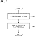
- FIG. 1 is a flowchart illustrating one example of a method for surface treatment according to the embodiment.
- the method for surface treatment illustrated in FIG. 1 is a method of smoothing the surface of a workpiece.
- the workpiece is a target on which the surface treatment is performed.
- the workpiece is formed of metal such as iron, aluminum, titanium, stainless steel, copper alloy, or carbon steel, for example.
- the workpiece may be a sintered product of metal powder.
- the sintered product is manufactured by sintering metal powder by powder metallurgy.
- the workpiece may be an additively manufactured product.
- the additively manufactured product is manufactured by repeatedly irradiating metal powder with laser light.
- the workpiece may be a casting.
- the workpiece may be a cutting-worked product.
- the workpiece may be a forging.
- the method for surface treatment includes performing blasting (Step S10) and irradiating with electron beam (Step S20).
- the blasting is performed by a blasting apparatus.
- the irradiating with electron beam is performed by an electron beam irradiation apparatus.
- FIG. 2 is a schematic view illustrating one example of the blasting apparatus.
- Blasting is a treatment method of grinding the surface of the workpiece by projecting an abrasive material.
- the material of the abrasive material is selected from various materials such as metal, ceramic, glass, resin, and plant-derived substances.
- Metal is iron, zinc, or stainless steel, for example.
- Ceramic is alumina, silicon carbide, or zircon, for example.
- Resin is nylon resin, melamine resin, or urea resin, for example.
- Plant-derived substances are walnut or peach, for example.
- the shape of the abrasive material is selected from various shapes such as a spherical shape, a polygonal shape, a cylindrical shape, and an irregular shape.
- shots, grids, and cut wires can be selected.
- the shots are spherical particles.
- the grids are polygonal particles having acute angles.
- the cut wires are cylindrical shapes or cylindrical shapes with rounded corners.
- a blasting apparatus 10 illustrated in FIG. 2 is a direct-pressure-type blasting apparatus.
- the direct-pressure-type blasting apparatus is a pressurization-type blasting apparatus in other words.
- the blasting apparatus 10 includes a storage container 20 and a nozzle 30.
- the storage container 20 defines a space in which an abrasive material is stored on the inside and stores the abrasive material therein.
- the abrasive material is supplied to the storage container 20 from the outside. For example, an operator may supply the abrasive material to the storage container 20.
- the storage container 20 may reuse a part of the abrasive material used in the blasting.
- the abrasive material used in the blasting is supplied to the storage container 20 from a classification mechanism 14 described below.
- the storage container 20 is connected to the nozzle 30 via a fixed quantity supplying unit 21 and a pipe 13.
- the fixed quantity supplying unit 21 is an apparatus that sends out the abrasive material stored in the storage container 20 to the pipe 13 and is a screw feeder as one example.
- a gas supply source 12 that supplies gas is connected to the pipe 13.
- the gas supply source 12 include a compressor or a gas cylinder that supplies gas of medium pressure, and an air blowing machine such as a fan or blower that supplies gas of low pressure.
- the medium pressure is a pressure within a range of from 0.1 MPa to 0.6 MPa, for example.
- the low pressure is a pressure within a range of from 0.01 MPa to 0.1 MPa, for example.
- compressed air is supplied by a compressor.
- the gas supplied to the pipe 13 from the gas supply source 12 carries the abrasive material sent out by the fixed quantity supplying unit 21 to the nozzle 30.
- the nozzle 30 sprays, together with the gas, the abrasive material supplied from the storage container 20.
- the nozzle 30 is housed in a treatment chamber 31, and a solid-gas two-phase flow in which the abrasive material supplied from the storage container 20 and gas are mixed is supplied to the nozzle 30 via the pipe 13.
- the nozzle 30 sprays, together with the gas, the abrasive material toward a workpiece W disposed in the treatment chamber 31.
- blasting is performed on the workpiece W.
- the workpiece W may be supported by a table that is not shown, and the position may be adjustable by a table driving mechanism.
- a lower portion of the treatment chamber 31 is connected to the storage container 20 via the classification mechanism 14. Swarf of the workpiece W and the abrasive material that have fallen down to the lower portion of the treatment chamber 31 are sucked into a dust collector that is not shown and pass through the classification mechanism 14.
- the classification mechanism 14 classifies reusable abrasive material and other minute powder such as the swarf of the workpiece W and crushed abrasive material. Other minute powder is collected into the dust collector.
- a lower portion of the classification mechanism 14 is connected to an upper portion of the storage container 20.
- the reusable abrasive material is supplied to the storage container 20 from the classification mechanism 14. When the abrasive material is not reusable, the blasting apparatus 10 does not necessarily need to include the classification mechanism 14.
- the blasting apparatus 10 is controlled by a control apparatus 11.
- the control apparatus 11 is configured as a programmable logic controller (PLC), for example.
- the control apparatus 11 may be configured as a computer system including a processor such as a central processing unit (CPU), a memory such as a random access memory (RAM) and a read only memory (ROM), an input-output apparatus such as a touch screen, a mouse, a keyboard, and a display, and a communication apparatus such as a network card.
- the control apparatus 11 realizes a function of the control apparatus 11 by causing each hardware to operate under the control of the processor based on a computer program stored in the memory.
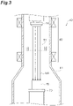
- FIG. 3 is a schematic view illustrating one example of an electron beam irradiation apparatus.
- An electron beam irradiation apparatus 40 illustrated in FIG. 3 is an apparatus that irradiates the workpiece W with electron beam EB and performs surface treatment of the workpiece W.
- the electron beam irradiation apparatus 40 includes a vacuum chamber 41, a cathode 50, an anode 51, a pair of solenoids 60, and a stage 70.
- the vacuum chamber 41 stores therein the workpiece W irradiated with the electron beam EB and a generation source of the electron beam EB.
- the workpiece W irradiated with the electron beam is placed on the stage 70 in the vacuum chamber 41.
- the cathode 50 that is the generation source of the electron beam EB is disposed in the vacuum chamber 41 in such a way as to face the stage 70.
- the ring-shaped anode 51 is disposed between the stage 70 and the cathode 50.
- the stage 70, the cathode 50, and the anode 51 are disposed in such a way as to be arranged on one axis in the vacuum chamber 41.
- Each of the pair of solenoids 60 is a ring-shaped member.
- the first solenoid is disposed on the outside of the vacuum chamber 41 in such a way as to surround the cathode 50
- the second solenoid is disposed on the outside of the vacuum chamber 41 in such a way as to surround the anode 51.
- a vacuum pump that is not shown such as a rotary pump and a turbopump is connected to the vacuum chamber 41.
- the vacuum chamber 41 is vacuumed in advance when the irradiation with the electron beam EB is performed.
- Inert gas such as Ar (argon) gas is introduced to the vacuumed vacuum chamber 41 from the outside, and the inside of the vacuum chamber 41 is maintained with an inert gas atmosphere of from about 5 to about 15 ⁇ 10 -2 Pa.
- a power source that is not shown that applies pulse voltage is connected to the cathode 50 and the anode 51 stored in the vacuum chamber 41.
- Another power source that is not shown that is different from the power source connected to the cathode 50 and the anode 51 is connected to the solenoids 60.
- the solenoids 60 When voltage is applied to the solenoids 60, the solenoids 60 generate a magnetic field near the anode 51 in the vacuum chamber 41. When the magnetic field generated near the anode 51 becomes the maximum, a pulse voltage is applied to the anode 51. Electrons in the vacuum chamber 41 move toward the anode 51 to which the voltage has been applied. At this time, the electrons move while drawing a spiral by the Lorentz force because the magnetic field is generated near the anode 51 by the solenoids 60. The electrons repeat collision with gas molecules, and the gas molecules that have collided with the electrons are ionized into positive ions and electrons. The positive ions and the electrons further repeat collision with the gas. A plasma is formed near each of the cathode 50 and the anode 51.
- a pulse voltage is applied to the cathode 50.
- the potential difference between the cathode 50 and the plasma near the cathode 50 becomes the maximum.
- the cathode 50 and an electric field in which the plasma is generated near the cathode 50 the electrons emitted from the cathode 50 are accelerated toward the anode 51 and generate the electron beam EB.
- the electron beam EB passes through the ring-shaped anode 51 and is applied to the workpiece W placed on the stage 70.
- Step S10 blasting is performed on the surface of the workpiece by the blasting apparatus 10. As a result, the workpiece surface is physically cut.
- Step S20 As an electron beam irradiating with electron beam(Step S20), the blasted surface of the workpiece is irradiated with electron beam by the electron beam irradiation apparatus 40. Minute unevenness of the surface of the workpiece is molten by the irradiation with the electron beam and is smoothed. Specifically, minute protruding portions are molten by the electron beam and the molten metal flows into minute recessed portions. As a result, the surface of the workpiece is smoothed.
- FIG. 4 is a block diagram illustrating one example of a surface treatment system according to the embodiment.
- a surface treatment system 90 includes the blasting apparatus 10, the electron beam irradiation apparatus 40, and a control unit 80.
- the control unit 80 is configured as a PLC as one example and is connected to the blasting apparatus 10 and the electron beam irradiation apparatus 40 in a manner in which communication is possible.
- the control unit 80 may be configured as the computer system described above.
- the control unit 80 controls the blasting apparatus 10 and the electron beam irradiation apparatus 40.
- the blasting apparatus 10 performs blasting on the workpiece W by the control of the control unit 80, and the electron beam irradiation apparatus 40 performs irradiation with the electron beam on the workpiece W on which blasting has been performed by the control of the control unit 80.
- the surface treatment system 90 can control each of the blasting apparatus 10 and the electron beam irradiation apparatus 40 and execute the method for surface treatment illustrated in FIG. 1 .
- the blasted surface of the workpiece W is irradiated with the electron beam.
- the blasted surface of the workpiece W has a shape that easily melts by the electron beam.
- unevenness of 100 ⁇ m or more may be physically cut. It can be said that the blasted surface of the workpiece W has a shape that easily melts by the electron beam because the melting speed of the unevenness of 100 ⁇ m or more due to the irradiation with the electron beam tends to be slow as compared to unevenness less than 100 ⁇ m.
- the method for surface treatment according to the present embodiment can control the surface of the workpiece W to be a shape that easily melts by the electron beam.
- the reduction rate of the surface roughness of the workpiece increases. Therefore, the method for surface treatment according to the present embodiment can efficiently smooth the workpiece by the irradiation with the electron beam.
- the method for surface treatment according to the present embodiment can shorten the time of irradiating with electron beam as compared to a case where only the irradiation with the electron beam is performed even when the workpiece W is a sintered product or an additively manufactured product with relatively high surface roughness.
- the method for surface treatment according to the present embodiment can also remove, by the electron beam, flaws formed on the surface of the workpiece W by the blasting.
- the blasting apparatus 10 is not limited to a direct-pressure-type blasting apparatus and may be a gravity-type air blast apparatus or centrifugal-type blast apparatus.
- the gravity-type air blast apparatus is a suction-type air blast apparatus in other words.
- the workpiece W As the workpiece W, an additively manufactured product that was a substantially cubic shape in which one edge was 50 mm was prepared.
- the workpiece W was obtained by performing additive manufacturing with Ti6Al4V ELI powder that is metal powder manufactured by Arcam AB.
- Arcam A2X Arcam A2X that is an additive manufacturing apparatus manufactured by Arcam AB was used. A number of 16 of the same workpieces W were prepared.
- blasting was performed on each of 15 workpieces W out of the 16 workpieces W with use of the blasting apparatus 10 illustrated in FIG. 2 under set blast conditions.
- the type of the projection material was steel grids or steel shots
- the lower limit value of the hardness of the projection material was from 450 HV to 800 HV
- the granularity was from 0.2 mm to 2.5 mm.
- FIG. 5 is one example of irradiation with the electron beam performed on the workpieces.
- a mask material M was used in order to compare surface states before and after the irradiation with the electron beam EB.
- the mask material M was a mask made of copper having a 25-mm-square opening S.
- the workpiece W in a state of being covered with the mask material M was irradiated with the electron beam EB.
- the pulse width was 2 ⁇ s
- the pulse frequency was 0.125 Hz
- the energy density was 15 J/cm 2
- the number of pulse irradiations was 50 times.
- the surface roughness before and after the electron beam irradiation were confirmed.
- the surface roughness was evaluated with use of the maximum height roughness Rz ( ⁇ m) and the mean width of roughness profile elements RSm ( ⁇ m) defined in (Japanese Industrial Standards : JIS B0601: 2001).
- RSm ( ⁇ m) mean spacing of profile elements.
- the maximum height roughness Rz ( ⁇ m) was the difference between the highest point and the lowest point from the roughness curve of the surface of the workpiece W.
- the mean width of roughness profile elements RSm ( ⁇ m) was the average value of the lengths of contour curve elements in the reference length of the roughness curve of the surface of the workpiece W.
- the reduction rate (%) of the maximum height roughness Rz was calculated with use of the maximum height roughness Rz ( ⁇ m) before and after the irradiation with the electron beam EB.
- the reduction rate (%) of the maximum height roughness Rz was a rate by which the irradiation with the electron beam EB smoothed the surface of the workpiece W and was calculated by the following expression.
- Reduction rate % of maximum height roughness Rz 1 ⁇ Maximum height roughness Rz after irradiation with electron beam / Maximum height roughness Rz before irradiation with electron beam ⁇ 100
- FIG. 6 is a table showing the evaluation results of the surface roughness.
- a blast condition "1" shown in FIG. 6 is an evaluation result (comparative example) of the surface roughness for the unblasted workpiece W that is the comparative example.
- Blast conditions "2" to "16" shown in FIG. 6 are evaluation results of the surface roughness for the blasted workpieces W that are the examples.
- the Rz of the unblasted workpiece W was 174.51 ⁇ m before the irradiation with the electron beam EB and was reduced to 139.75 ⁇ m after the irradiation with the electron beam EB.
- the reduction rate of the Rz was 20%.
- the RSm was 367.35 ⁇ m before the irradiation with the electron beam EB and increased to 752.66 ⁇ m after the irradiation with the electron beam EB.
- the workpiece W was blasted with steel grids, the Vickers hardness of which was 450 HV and granularity was 1.4 mm.
- the Rz of the blasted workpiece W was 53.19 ⁇ m before the irradiation with the electron beam EB and decreased to 45.68 ⁇ m after the irradiation with the electron beam EB. In this case, the reduction rate of the Rz was 14%.
- the RSm was 1091.55 ⁇ m before the irradiation with the electron beam EB and increased to 1322.48 ⁇ m after the irradiation with the electron beam EB.
- the workpiece W was blasted with steel grids, the Vickers hardness of which was more than 800 HV and granularity was 0.7 mm.
- the Rz of the blasted workpiece W was 54.66 ⁇ m before the irradiation with the electron beam EB and decreased to 24.65 ⁇ m after the irradiation with the electron beam EB. In this case, the reduction rate of the Rz was 55%.
- the RSm was 391.86 ⁇ m before the irradiation with the electron beam EB and increased to 1291.25 ⁇ m after the irradiation with the electron beam EB.
- the workpiece W was blasted with steel grids, the Vickers hardness of which was more than 800 HV and granularity was 0.7 mm.
- the Rz of the blasted workpiece W was 65.99 ⁇ m before the irradiation with the electron beam EB and decreased to 27.98 ⁇ m after the irradiation with the electron beam EB. In this case, the reduction rate of the Rz was 58%.
- the RSm was 433.89 ⁇ m before the irradiation with the electron beam EB and increased to 1098.82 ⁇ m after the irradiation with the electron beam EB.
- the workpiece W was blasted with steel shots, the Vickers hardness of which was 450 HV and granularity was 1.0 mm.
- the Rz of the blasted workpiece W was 45.43 ⁇ m before the irradiation with the electron beam EB and decreased to 34.36 ⁇ m after the irradiation with the electron beam EB. In this case, the reduction rate of the Rz was 24%.
- the RSm was 860.99 ⁇ m before the irradiation with the electron beam EB and increased to 1180.18 ⁇ m after the irradiation with the electron beam EB.
- the workpiece W was blasted with steel shots, the Vickers hardness of which was 450 HV and granularity was 2.5 mm.
- the Rz of the blasted workpiece W was 45.36 ⁇ m before the irradiation with the electron beam EB and decreased to 32.19 ⁇ m after the irradiation with the electron beam EB. In this case, the reduction rate of the Rz was 29%.
- the RSm was 922.88 ⁇ m before the irradiation with the electron beam EB and increased to 937.18 ⁇ m after the irradiation with the electron beam EB.
- the workpiece W was blasted with steel shots, the Vickers hardness of which was 450 HV and granularity was 1.4 mm.
- the Rz of the blasted workpiece W was 45.45 ⁇ m before the irradiation with the electron beam EB and decreased to 35.67 ⁇ m after the irradiation with the electron beam EB. In this case, the reduction rate of the Rz was 22%.
- the RSm was 1009.34 ⁇ m before the irradiation with the electron beam EB and decreased to 956.43 ⁇ m after the irradiation with the electron beam EB.
- the workpiece W was blasted with steel shots, the Vickers hardness of which was 450 HV and granularity was 0.6 mm.
- the Rz of the blasted workpiece W was 47.04 ⁇ m before the irradiation with the electron beam EB and decreased to 38.62 ⁇ m after the irradiation with the electron beam EB. In this case, the reduction rate of the Rz was 18%.
- the RSm was 959.69 ⁇ m before the irradiation with the electron beam EB and increased to 1234.12 ⁇ m after the irradiation with the electron beam EB.
- the workpiece W was blasted with steel shots, the Vickers hardness of which was 450 HV and granularity was 2.5 mm.
- the Rz of the blasted workpiece W was 39.45 ⁇ m before the irradiation with the electron beam EB and decreased to 35.29 ⁇ m after the irradiation with the electron beam EB. In this case, the reduction rate of the Rz was 11%.
- the RSm was 1024.41 ⁇ m before the irradiation with the electron beam EB and increased to 1400.89 ⁇ m after the irradiation with the electron beam EB.
- the workpiece W was blasted with steel grids, the Vickers hardness of which was more than 800 HV and granularity was 0.3 mm.
- the Rz of the blasted workpiece W was 44.08 ⁇ m before the irradiation with the electron beam EB and decreased to 27.91 ⁇ m after the irradiation with the electron beam EB (the reduction rate of the Rz was 37%.)
- the RSm was 582.93 ⁇ m before the irradiation with the electron beam EB and increased to 1298.67 ⁇ m after the irradiation with the electron beam EB.
- the workpiece W was blasted with steel grids, the Vickers hardness of which was 450 HV and granularity was 0.7 mm.
- the Rz of the blasted workpiece W was 53.04 ⁇ m before the irradiation with the electron beam EB and decreased to 28.44 ⁇ m after the irradiation with the electron beam EB. In this case, the reduction rate of the Rz was 46%.
- the RSm was 610.62 ⁇ m before the irradiation with the electron beam EB and increased to 1114.42 ⁇ m after the irradiation with the electron beam EB.
- the workpiece W was blasted with steel grids, the Vickers hardness of which was 600 HV and granularity was 0.7 mm.
- the Rz of the blasted workpiece W was 53.98 ⁇ m before the irradiation with the electron beam EB and decreased to 37.35 ⁇ m after the irradiation with the electron beam EB. In this case, the reduction rate of the Rz was 31%.
- the RSm was 770.80 ⁇ m before the irradiation with the electron beam EB and increased to 1154.21 ⁇ m after the irradiation with the electron beam EB.
- the workpiece W was blasted with steel grids, the Vickers hardness of which was more than 800 HV and granularity was 0.2 mm.
- the Rz of the blasted workpiece W was 63.02 ⁇ m before the irradiation with the electron beam EB and decreased to 51.61 ⁇ m after the irradiation with the electron beam EB. In this case, the reduction rate of the Rz was 18%.
- the RSm was 781.94 ⁇ m before the irradiation with the electron beam EB and increased to 1136.86 ⁇ m after the irradiation with the electron beam EB.
- the workpiece W was blasted with steel grids, the Vickers hardness of which was more than 800 HV and granularity was 0.2 mm.
- the Rz of the blasted workpiece W was 38.16 ⁇ m before the irradiation with the electron beam EB and decreased to 24.31 ⁇ m after the irradiation with the electron beam EB. In this case, the reduction rate of the Rz was 36%.
- the RSm was 496.27 ⁇ m before the irradiation with the electron beam EB and increased to 1311.28 ⁇ m after the irradiation with the electron beam EB.
- the workpiece W was blasted with steel grids, the Vickers hardness of which was more than 800 HV and granularity was 0.2 mm.
- the Rz of the blasted workpiece W was 49.53 ⁇ m before the irradiation with the electron beam EB and decreased to 38.95 ⁇ m after the irradiation with the electron beam EB. In this case, the reduction rate of the Rz was 21%.
- the RSm was 852.99 ⁇ m before the irradiation with the electron beam EB and increased to 1195.85 ⁇ m after the irradiation with the electron beam EB.
- the workpiece W was blasted with steel grids, the Vickers hardness of which was more than 800 HV and granularity was 0.2 mm.
- the Rz of the blasted workpiece W was 32.90 ⁇ m before the irradiation with the electron beam EB and decreased to 16.18 ⁇ m after the irradiation with the electron beam EB. In this case, the reduction rate of the Rz was 51%.
- the RSm was 299.65 ⁇ m before the irradiation with the electron beam EB and increased to 1248.80 ⁇ m after the irradiation with the electron beam EB.
- the Rz after the irradiation with the electron beam EB was within the range of from 16.18 ⁇ m to 51.61 ⁇ m. Meanwhile, in the unblasted workpiece W on which only the irradiation with the electron beam EB was performed, the Rz after the irradiation with the electron beam EB was 139.75 ⁇ m. Therefore, it was confirmed that the surface of the workpiece W can be further smoothed by irradiating the surface of the workpiece W on which the blasting was performed with the electron beam EB.
- FIG. 7 is a scatter diagram showing the correlation between the RSm and the reduction rate of the Rz.
- the abscissa is the RSm before the irradiation with the electron beam EB and the ordinate is the reduction rate of the Rz.
- data is shown by classifying the data into six data: no blasting (the blast condition "1"); blasting with steel shots (the blast conditions "5" to “9”); the Rz after the blasting with steel grids being less than 40 ⁇ m (the blast conditions "9” and “16”); the Rz after the blasting with steel grids being from 40 ⁇ m to 50 ⁇ m (the blast conditions "10” and “15”); the Rz after the blasting with steel grids being from 50 ⁇ m to 60 ⁇ m (the blast conditions "2", “3", “11", and “12”); and the Rz after the blasting with steel grids being 60 ⁇ m or more in accordance with the blast conditions.
- FIGS. 8A to 8E are cross-section observation results of the workpieces W before the irradiation with the electron beam EB.
- FIG. 8A is an observation result (the blast condition "1") of the unblasted workpiece W
- FIGS. 8B and 8D are observation results (the blast condition "12") of the blasted workpiece W.
- FIG. 8D is an enlarged view of FIG. 8B.
- FIGS. 8C and 8E are observation results (the blast condition "16") of the blasted workpiece W.
- FIG. 8E is an enlarged view of FIG. 8C .
- FIG. 8A in the unblasted workpiece W, minute unevenness of 100 ⁇ m or less and large unevenness more than 100 ⁇ m were confirmed.
- FIGS. 8F to 8H are cross-section observation results after the irradiation with the electron beam EB.
- FIG. 8F is an observation result after the workpiece according to FIG. 8A was irradiated with the electron beam EB.
- FIG. 8G is an observation result after the workpiece W according to FIGS. 8B and 8D was irradiated with the electron beam EB.
- FIG. 8H is an observation result after the workpiece W according to FIGS. 8C and 8E was irradiated with the electron beam EB.
- FIG. 8F by the irradiation with the electron beam EB, the minute unevenness that was 100 ⁇ m or less confirmed before the irradiation with the electron beam EB was removed.
- the blasting was able to remove unevenness more than 100 ⁇ m that was not able to be removed by the irradiation with the electron beam EB.
- the blasting was able to control the surface to be a shape that easily melts by the electron beam. Therefore, it was confirmed that the method for surface treatment that performs the irradiation with the electron beam EB after performing blasting was able to efficiently smooth the surface of the workpiece W. It was confirmed that the irradiation with the electron beam EB was able to remove cracks caused by the blasting.
Landscapes
- Engineering & Computer Science (AREA)
- Mechanical Engineering (AREA)
- Chemical & Material Sciences (AREA)
- Manufacturing & Machinery (AREA)
- Materials Engineering (AREA)
- Physics & Mathematics (AREA)
- Plasma & Fusion (AREA)
- Thermal Sciences (AREA)
- Optics & Photonics (AREA)
- Analytical Chemistry (AREA)
- Metallurgy (AREA)
- Organic Chemistry (AREA)
- Welding Or Cutting Using Electron Beams (AREA)
- Application Of Or Painting With Fluid Materials (AREA)
Abstract
Description
- This application is based on
Japanese Patent Application No. 2021-029702 filed with Japan Patent Office on February 26, 2021 - The present disclosure relates to a method for surface treatment and a surface treatment system.
-
Japanese Unexamined Patent Publication No. 2004-001086 - In the method of
Japanese Unexamined Patent Publication No. 2004-1086 - The inventor of the present invention has focused on a fact that blasting can control the surface state with a principle different from that of melting, and has found that the reduction rate of the surface roughness of a workpiece increases when blasting is performed before irradiation with electron beam as compared to a case where only the irradiation with the electron beam is performed. In other words, it has been found that a ratio of decrease of the roughness of the workpiece increases in comparison before and after the electron beam irradiation.
- In other words, a method for surface treatment according to one aspect of the present disclosure is a method for surface treatment includes: performing blasting on a surface of the workpiece; and irradiating the blasted surface of the workpiece with electron beam. According to the method for surface treatment, the workpiece can be efficiently smoothed by the irradiation with the electron beam because the reduction rate of the surface roughness of the workpiece increases as compared to a case where only the irradiation with the electron beam is performed.
- In one embodiment, the workpiece may be a sintered product of metal powder. In one embodiment, the workpiece may be an additively manufactured product. The roughness of the surface of a sintered product or an additively manufactured product tends to be relatively large. The method for surface treatment can even efficiently cause the surface of a sintered product or an additively manufactured product to be flat.
- In one embodiment, a mean width of roughness profile elements of the blasted surface of the workpiece may be less than 770.80 µm. In this case, the method for surface treatment can cause the reduction rate of the surface roughness of the workpiece to be 20% or more.
- A surface treatment system according to another aspect of the present embodiment includes: a blasting apparatus configured to perform blasting on a workpiece; an electron beam irradiation apparatus configured to irradiate the workpiece with electron beam; and a control unit configured to control the blasting apparatus and the electron beam irradiation apparatus. The control unit causes the blasting apparatus to perform blasting on a surface of the workpiece by controlling the blasting apparatus, and causes the electron beam irradiation apparatus to irradiate, with the electron beam, the surface of the blasted workpiece by controlling the electron beam irradiation apparatus. As with the surface treatment apparatus described above, the surface treatment system can efficiently smooth the workpiece by the irradiation with the electron beam as compared to a case where only the irradiation with the electron beam is performed.
- According to the present disclosure, the workpiece can be efficiently smoothed by the irradiation of the electron beam.
-
-
FIG. 1 is a flowchart illustrating one example of a method for surface treatment according to an embodiment; -
FIG. 2 is a schematic view illustrating one example of a blasting apparatus; -
FIG. 3 is a schematic view illustrating one example of an electron beam irradiation apparatus; -
FIG. 4 is a block diagram illustrating one example of a surface treatment system according to the embodiment; -
FIG. 5 is one example of irradiation with electron beam performed on a workpiece; -
FIG. 6 is a table showing evaluation results of the surface roughness; -
FIG. 7 is a scatter diagram showing the correlation between the RSm (mean width of roughness profile roughness elements) and the Rz (maximum height roughness) reduction rate; and -
FIGS. 8A to 8E are cross-section observation results of workpieces before and after the electron beam irradiation. - An embodiment of the present disclosure is described below with reference to the drawings. In the description below, the same or equivalent elements are denoted by the same reference characters, and overlapping description is not repeated. Dimension ratios of the drawings do not necessarily match with those described. Terms "up", "down", "left", and "right" are based on the illustrated states and are for convenience.
-
FIG. 1 is a flowchart illustrating one example of a method for surface treatment according to the embodiment. The method for surface treatment illustrated inFIG. 1 is a method of smoothing the surface of a workpiece. The workpiece is a target on which the surface treatment is performed. The workpiece is formed of metal such as iron, aluminum, titanium, stainless steel, copper alloy, or carbon steel, for example. The workpiece may be a sintered product of metal powder. The sintered product is manufactured by sintering metal powder by powder metallurgy. The workpiece may be an additively manufactured product. The additively manufactured product is manufactured by repeatedly irradiating metal powder with laser light. The workpiece may be a casting. The workpiece may be a cutting-worked product. The workpiece may be a forging. - As illustrated in
FIG. 1 , the method for surface treatment includes performing blasting (Step S10) and irradiating with electron beam (Step S20). The blasting is performed by a blasting apparatus. The irradiating with electron beam is performed by an electron beam irradiation apparatus. First, the outline of apparatus examples used in each step is described. -
FIG. 2 is a schematic view illustrating one example of the blasting apparatus. Blasting is a treatment method of grinding the surface of the workpiece by projecting an abrasive material. The material of the abrasive material is selected from various materials such as metal, ceramic, glass, resin, and plant-derived substances. Metal is iron, zinc, or stainless steel, for example. Ceramic is alumina, silicon carbide, or zircon, for example. Resin is nylon resin, melamine resin, or urea resin, for example. Plant-derived substances are walnut or peach, for example. The shape of the abrasive material is selected from various shapes such as a spherical shape, a polygonal shape, a cylindrical shape, and an irregular shape. For example, in the case of metal particles, shots, grids, and cut wires can be selected. The shots are spherical particles. The grids are polygonal particles having acute angles. The cut wires are cylindrical shapes or cylindrical shapes with rounded corners. - A blasting
apparatus 10 illustrated inFIG. 2 is a direct-pressure-type blasting apparatus. The direct-pressure-type blasting apparatus is a pressurization-type blasting apparatus in other words. As illustrated inFIG. 2 , the blastingapparatus 10 includes astorage container 20 and anozzle 30. Thestorage container 20 defines a space in which an abrasive material is stored on the inside and stores the abrasive material therein. The abrasive material is supplied to thestorage container 20 from the outside. For example, an operator may supply the abrasive material to thestorage container 20. Thestorage container 20 may reuse a part of the abrasive material used in the blasting. In this case, the abrasive material used in the blasting is supplied to thestorage container 20 from aclassification mechanism 14 described below. Thestorage container 20 is connected to thenozzle 30 via a fixedquantity supplying unit 21 and apipe 13. The fixedquantity supplying unit 21 is an apparatus that sends out the abrasive material stored in thestorage container 20 to thepipe 13 and is a screw feeder as one example. - A
gas supply source 12 that supplies gas is connected to thepipe 13. Examples of thegas supply source 12 include a compressor or a gas cylinder that supplies gas of medium pressure, and an air blowing machine such as a fan or blower that supplies gas of low pressure. The medium pressure is a pressure within a range of from 0.1 MPa to 0.6 MPa, for example. The low pressure is a pressure within a range of from 0.01 MPa to 0.1 MPa, for example. In the present embodiment, as one example, compressed air is supplied by a compressor. The gas supplied to thepipe 13 from thegas supply source 12 carries the abrasive material sent out by the fixedquantity supplying unit 21 to thenozzle 30. - The
nozzle 30 sprays, together with the gas, the abrasive material supplied from thestorage container 20. Thenozzle 30 is housed in atreatment chamber 31, and a solid-gas two-phase flow in which the abrasive material supplied from thestorage container 20 and gas are mixed is supplied to thenozzle 30 via thepipe 13. Thenozzle 30 sprays, together with the gas, the abrasive material toward a workpiece W disposed in thetreatment chamber 31. As a result, blasting is performed on the workpiece W. The workpiece W may be supported by a table that is not shown, and the position may be adjustable by a table driving mechanism. - A lower portion of the
treatment chamber 31 is connected to thestorage container 20 via theclassification mechanism 14. Swarf of the workpiece W and the abrasive material that have fallen down to the lower portion of thetreatment chamber 31 are sucked into a dust collector that is not shown and pass through theclassification mechanism 14. Theclassification mechanism 14 classifies reusable abrasive material and other minute powder such as the swarf of the workpiece W and crushed abrasive material. Other minute powder is collected into the dust collector. A lower portion of theclassification mechanism 14 is connected to an upper portion of thestorage container 20. The reusable abrasive material is supplied to thestorage container 20 from theclassification mechanism 14. When the abrasive material is not reusable, the blastingapparatus 10 does not necessarily need to include theclassification mechanism 14. - The blasting
apparatus 10 is controlled by acontrol apparatus 11. Thecontrol apparatus 11 is configured as a programmable logic controller (PLC), for example. Thecontrol apparatus 11 may be configured as a computer system including a processor such as a central processing unit (CPU), a memory such as a random access memory (RAM) and a read only memory (ROM), an input-output apparatus such as a touch screen, a mouse, a keyboard, and a display, and a communication apparatus such as a network card. Thecontrol apparatus 11 realizes a function of thecontrol apparatus 11 by causing each hardware to operate under the control of the processor based on a computer program stored in the memory. -
FIG. 3 is a schematic view illustrating one example of an electron beam irradiation apparatus. An electronbeam irradiation apparatus 40 illustrated inFIG. 3 is an apparatus that irradiates the workpiece W with electron beam EB and performs surface treatment of the workpiece W. As illustrated inFIG. 3 , the electronbeam irradiation apparatus 40 includes avacuum chamber 41, acathode 50, ananode 51, a pair ofsolenoids 60, and astage 70. - The
vacuum chamber 41 stores therein the workpiece W irradiated with the electron beam EB and a generation source of the electron beam EB. The workpiece W irradiated with the electron beam is placed on thestage 70 in thevacuum chamber 41. Thecathode 50 that is the generation source of the electron beam EB is disposed in thevacuum chamber 41 in such a way as to face thestage 70. The ring-shapedanode 51 is disposed between thestage 70 and thecathode 50. Thestage 70, thecathode 50, and theanode 51 are disposed in such a way as to be arranged on one axis in thevacuum chamber 41. Each of the pair ofsolenoids 60 is a ring-shaped member. The first solenoid is disposed on the outside of thevacuum chamber 41 in such a way as to surround thecathode 50, and the second solenoid is disposed on the outside of thevacuum chamber 41 in such a way as to surround theanode 51. - A vacuum pump that is not shown such as a rotary pump and a turbopump is connected to the
vacuum chamber 41. Thevacuum chamber 41 is vacuumed in advance when the irradiation with the electron beam EB is performed. Inert gas such as Ar (argon) gas is introduced to the vacuumedvacuum chamber 41 from the outside, and the inside of thevacuum chamber 41 is maintained with an inert gas atmosphere of from about 5 to about 15×10-2 Pa. - A power source that is not shown that applies pulse voltage is connected to the
cathode 50 and theanode 51 stored in thevacuum chamber 41. Another power source that is not shown that is different from the power source connected to thecathode 50 and theanode 51 is connected to thesolenoids 60. - When voltage is applied to the
solenoids 60, thesolenoids 60 generate a magnetic field near theanode 51 in thevacuum chamber 41. When the magnetic field generated near theanode 51 becomes the maximum, a pulse voltage is applied to theanode 51. Electrons in thevacuum chamber 41 move toward theanode 51 to which the voltage has been applied. At this time, the electrons move while drawing a spiral by the Lorentz force because the magnetic field is generated near theanode 51 by thesolenoids 60. The electrons repeat collision with gas molecules, and the gas molecules that have collided with the electrons are ionized into positive ions and electrons. The positive ions and the electrons further repeat collision with the gas. A plasma is formed near each of thecathode 50 and theanode 51. - When the plasma generated near the
anode 51 becomes the maximum, a pulse voltage is applied to thecathode 50. At this time, the potential difference between thecathode 50 and the plasma near thecathode 50 becomes the maximum. As a result, by thecathode 50 and an electric field in which the plasma is generated near thecathode 50, the electrons emitted from thecathode 50 are accelerated toward theanode 51 and generate the electron beam EB. The electron beam EB passes through the ring-shapedanode 51 and is applied to the workpiece W placed on thestage 70. - A method for surface treatment is described below by referring to
FIG. 1 again. First, as performing blasting (Step S10), blasting is performed on the surface of the workpiece by the blastingapparatus 10. As a result, the workpiece surface is physically cut. - Next, as an electron beam irradiating with electron beam(Step S20), the blasted surface of the workpiece is irradiated with electron beam by the electron
beam irradiation apparatus 40. Minute unevenness of the surface of the workpiece is molten by the irradiation with the electron beam and is smoothed. Specifically, minute protruding portions are molten by the electron beam and the molten metal flows into minute recessed portions. As a result, the surface of the workpiece is smoothed. - The method for surface treatment illustrated in
FIG. 1 may be executed by a surface treatment system.FIG. 4 is a block diagram illustrating one example of a surface treatment system according to the embodiment. As illustrated inFIG. 4 , asurface treatment system 90 includes the blastingapparatus 10, the electronbeam irradiation apparatus 40, and acontrol unit 80. Thecontrol unit 80 is configured as a PLC as one example and is connected to theblasting apparatus 10 and the electronbeam irradiation apparatus 40 in a manner in which communication is possible. Thecontrol unit 80 may be configured as the computer system described above. Thecontrol unit 80 controls the blastingapparatus 10 and the electronbeam irradiation apparatus 40. The blastingapparatus 10 performs blasting on the workpiece W by the control of thecontrol unit 80, and the electronbeam irradiation apparatus 40 performs irradiation with the electron beam on the workpiece W on which blasting has been performed by the control of thecontrol unit 80. As described above, thesurface treatment system 90 can control each of the blastingapparatus 10 and the electronbeam irradiation apparatus 40 and execute the method for surface treatment illustrated inFIG. 1 . - In the method for surface treatment according to the present embodiment, the blasted surface of the workpiece W is irradiated with the electron beam. The blasted surface of the workpiece W has a shape that easily melts by the electron beam. As one example, in the blasted surface of the workpiece W, unevenness of 100 µm or more may be physically cut. It can be said that the blasted surface of the workpiece W has a shape that easily melts by the electron beam because the melting speed of the unevenness of 100 µm or more due to the irradiation with the electron beam tends to be slow as compared to unevenness less than 100 µm. In other words, by performing blasting, the method for surface treatment according to the present embodiment can control the surface of the workpiece W to be a shape that easily melts by the electron beam. As a result, as compared to a case where only the irradiation with the electron beam is performed, the reduction rate of the surface roughness of the workpiece increases. Therefore, the method for surface treatment according to the present embodiment can efficiently smooth the workpiece by the irradiation with the electron beam.
- The method for surface treatment according to the present embodiment can shorten the time of irradiating with electron beam as compared to a case where only the irradiation with the electron beam is performed even when the workpiece W is a sintered product or an additively manufactured product with relatively high surface roughness. The method for surface treatment according to the present embodiment can also remove, by the electron beam, flaws formed on the surface of the workpiece W by the blasting.
- Various exemplary embodiments have been described above, but various omission, replacement, and modifications may be made without being limited to the abovementioned exemplary embodiments. For example, the blasting
apparatus 10 is not limited to a direct-pressure-type blasting apparatus and may be a gravity-type air blast apparatus or centrifugal-type blast apparatus. The gravity-type air blast apparatus is a suction-type air blast apparatus in other words. - Examples carried out by the inventor of the present invention are described in order to describe the abovementioned effects. The present disclosure is not limited to the examples.
- As the workpiece W, an additively manufactured product that was a substantially cubic shape in which one edge was 50 mm was prepared. The workpiece W was obtained by performing additive manufacturing with Ti6Al4V ELI powder that is metal powder manufactured by Arcam AB. For the additive manufacturing, Arcam A2X that is an additive manufacturing apparatus manufactured by Arcam AB was used. A number of 16 of the same workpieces W were prepared.
- Next, blasting was performed on each of 15 workpieces W out of the 16 workpieces W with use of the blasting
apparatus 10 illustrated inFIG. 2 under set blast conditions. As the blast condition, the type of the projection material was steel grids or steel shots, the lower limit value of the hardness of the projection material was from 450 HV to 800 HV, and the granularity was from 0.2 mm to 2.5 mm. As a result, 15 blasted workpieces W and one unblasted workpiece were obtained. - Next, with use of the electron
beam irradiation apparatus 40 illustrated inFIG. 3 , the surfaces of all of the 16 workpieces W were irradiated with the electron beam EB.FIG. 5 is one example of irradiation with the electron beam performed on the workpieces. As illustrated inFIG. 5 , a mask material M was used in order to compare surface states before and after the irradiation with the electron beam EB. The mask material M was a mask made of copper having a 25-mm-square opening S. The workpiece W in a state of being covered with the mask material M was irradiated with the electron beam EB. As the irradiation condition of the electron beam EB, the pulse width was 2 µs, the pulse frequency was 0.125 Hz, the energy density was 15 J/cm2, and the number of pulse irradiations was 50 times. - For the 15 blasted workpieces W that are the examples and the unblasted workpiece W that is a comparative example, the surface roughness before and after the electron beam irradiation were confirmed. The surface roughness was evaluated with use of the maximum height roughness Rz (µm) and the mean width of roughness profile elements RSm (µm) defined in (Japanese Industrial Standards : JIS B0601: 2001). In other words, RSm (µm) mean spacing of profile elements. The maximum height roughness Rz (µm) was the difference between the highest point and the lowest point from the roughness curve of the surface of the workpiece W. The mean width of roughness profile elements RSm (µm) was the average value of the lengths of contour curve elements in the reference length of the roughness curve of the surface of the workpiece W. The reduction rate (%) of the maximum height roughness Rz was calculated with use of the maximum height roughness Rz (µm) before and after the irradiation with the electron beam EB. The reduction rate (%) of the maximum height roughness Rz was a rate by which the irradiation with the electron beam EB smoothed the surface of the workpiece W and was calculated by the following expression.

- Evaluation results of the surface roughness are shown in
FIG. 6. FIG. 6 is a table showing the evaluation results of the surface roughness. A blast condition "1" shown inFIG. 6 is an evaluation result (comparative example) of the surface roughness for the unblasted workpiece W that is the comparative example. Blast conditions "2" to "16" shown inFIG. 6 are evaluation results of the surface roughness for the blasted workpieces W that are the examples. - As shown in the blast condition "1", the Rz of the unblasted workpiece W was 174.51 µm before the irradiation with the electron beam EB and was reduced to 139.75 µm after the irradiation with the electron beam EB. In this case, the reduction rate of the Rz was 20%. The RSm was 367.35 µm before the irradiation with the electron beam EB and increased to 752.66 µm after the irradiation with the electron beam EB.
- In the blast condition "2", the workpiece W was blasted with steel grids, the Vickers hardness of which was 450 HV and granularity was 1.4 mm. The Rz of the blasted workpiece W was 53.19 µm before the irradiation with the electron beam EB and decreased to 45.68 µm after the irradiation with the electron beam EB. In this case, the reduction rate of the Rz was 14%. Meanwhile, the RSm was 1091.55 µm before the irradiation with the electron beam EB and increased to 1322.48 µm after the irradiation with the electron beam EB.
- In the blast condition "3", the workpiece W was blasted with steel grids, the Vickers hardness of which was more than 800 HV and granularity was 0.7 mm. The Rz of the blasted workpiece W was 54.66 µm before the irradiation with the electron beam EB and decreased to 24.65 µm after the irradiation with the electron beam EB. In this case, the reduction rate of the Rz was 55%. Meanwhile, the RSm was 391.86 µm before the irradiation with the electron beam EB and increased to 1291.25 µm after the irradiation with the electron beam EB.
- In the blast condition "4", the workpiece W was blasted with steel grids, the Vickers hardness of which was more than 800 HV and granularity was 0.7 mm. The Rz of the blasted workpiece W was 65.99 µm before the irradiation with the electron beam EB and decreased to 27.98 µm after the irradiation with the electron beam EB. In this case, the reduction rate of the Rz was 58%. Meanwhile, the RSm was 433.89 µm before the irradiation with the electron beam EB and increased to 1098.82 µm after the irradiation with the electron beam EB.
- In the blast condition "5", the workpiece W was blasted with steel shots, the Vickers hardness of which was 450 HV and granularity was 1.0 mm. The Rz of the blasted workpiece W was 45.43 µm before the irradiation with the electron beam EB and decreased to 34.36 µm after the irradiation with the electron beam EB. In this case, the reduction rate of the Rz was 24%. Meanwhile, the RSm was 860.99 µm before the irradiation with the electron beam EB and increased to 1180.18 µm after the irradiation with the electron beam EB.
- In the blast condition "6", the workpiece W was blasted with steel shots, the Vickers hardness of which was 450 HV and granularity was 2.5 mm. The Rz of the blasted workpiece W was 45.36 µm before the irradiation with the electron beam EB and decreased to 32.19 µm after the irradiation with the electron beam EB. In this case, the reduction rate of the Rz was 29%. Meanwhile, the RSm was 922.88 µm before the irradiation with the electron beam EB and increased to 937.18 µm after the irradiation with the electron beam EB.
- In the blast condition "7", the workpiece W was blasted with steel shots, the Vickers hardness of which was 450 HV and granularity was 1.4 mm. The Rz of the blasted workpiece W was 45.45 µm before the irradiation with the electron beam EB and decreased to 35.67 µm after the irradiation with the electron beam EB. In this case, the reduction rate of the Rz was 22%. Meanwhile, the RSm was 1009.34 µm before the irradiation with the electron beam EB and decreased to 956.43 µm after the irradiation with the electron beam EB.
- In the blast condition "8", the workpiece W was blasted with steel shots, the Vickers hardness of which was 450 HV and granularity was 0.6 mm. The Rz of the blasted workpiece W was 47.04 µm before the irradiation with the electron beam EB and decreased to 38.62 µm after the irradiation with the electron beam EB. In this case, the reduction rate of the Rz was 18%. Meanwhile, the RSm was 959.69 µm before the irradiation with the electron beam EB and increased to 1234.12 µm after the irradiation with the electron beam EB.
- In the blast condition "9", the workpiece W was blasted with steel shots, the Vickers hardness of which was 450 HV and granularity was 2.5 mm. The Rz of the blasted workpiece W was 39.45 µm before the irradiation with the electron beam EB and decreased to 35.29 µm after the irradiation with the electron beam EB. In this case, the reduction rate of the Rz was 11%. Meanwhile, the RSm was 1024.41 µm before the irradiation with the electron beam EB and increased to 1400.89 µm after the irradiation with the electron beam EB.
- In the blast condition "10", the workpiece W was blasted with steel grids, the Vickers hardness of which was more than 800 HV and granularity was 0.3 mm. The Rz of the blasted workpiece W was 44.08 µm before the irradiation with the electron beam EB and decreased to 27.91 µm after the irradiation with the electron beam EB (the reduction rate of the Rz was 37%.) Meanwhile, the RSm was 582.93 µm before the irradiation with the electron beam EB and increased to 1298.67 µm after the irradiation with the electron beam EB.
- In the blast condition "11", the workpiece W was blasted with steel grids, the Vickers hardness of which was 450 HV and granularity was 0.7 mm. The Rz of the blasted workpiece W was 53.04 µm before the irradiation with the electron beam EB and decreased to 28.44 µm after the irradiation with the electron beam EB. In this case, the reduction rate of the Rz was 46%. Meanwhile, the RSm was 610.62 µm before the irradiation with the electron beam EB and increased to 1114.42 µm after the irradiation with the electron beam EB.
- In the blast condition "12", the workpiece W was blasted with steel grids, the Vickers hardness of which was 600 HV and granularity was 0.7 mm. The Rz of the blasted workpiece W was 53.98 µm before the irradiation with the electron beam EB and decreased to 37.35 µm after the irradiation with the electron beam EB. In this case, the reduction rate of the Rz was 31%. Meanwhile, the RSm was 770.80 µm before the irradiation with the electron beam EB and increased to 1154.21 µm after the irradiation with the electron beam EB.
- In the blast condition "13", the workpiece W was blasted with steel grids, the Vickers hardness of which was more than 800 HV and granularity was 0.2 mm. The Rz of the blasted workpiece W was 63.02 µm before the irradiation with the electron beam EB and decreased to 51.61 µm after the irradiation with the electron beam EB. In this case, the reduction rate of the Rz was 18%. Meanwhile, the RSm was 781.94 µm before the irradiation with the electron beam EB and increased to 1136.86 µm after the irradiation with the electron beam EB.
- In the blast condition "14", the workpiece W was blasted with steel grids, the Vickers hardness of which was more than 800 HV and granularity was 0.2 mm. The Rz of the blasted workpiece W was 38.16 µm before the irradiation with the electron beam EB and decreased to 24.31 µm after the irradiation with the electron beam EB. In this case, the reduction rate of the Rz was 36%. Meanwhile, the RSm was 496.27 µm before the irradiation with the electron beam EB and increased to 1311.28 µm after the irradiation with the electron beam EB.
- In the blast condition "15", the workpiece W was blasted with steel grids, the Vickers hardness of which was more than 800 HV and granularity was 0.2 mm. The Rz of the blasted workpiece W was 49.53 µm before the irradiation with the electron beam EB and decreased to 38.95 µm after the irradiation with the electron beam EB. In this case, the reduction rate of the Rz was 21%. Meanwhile, the RSm was 852.99 µm before the irradiation with the electron beam EB and increased to 1195.85 µm after the irradiation with the electron beam EB.
- In the blast condition "16", the workpiece W was blasted with steel grids, the Vickers hardness of which was more than 800 HV and granularity was 0.2 mm. The Rz of the blasted workpiece W was 32.90 µm before the irradiation with the electron beam EB and decreased to 16.18 µm after the irradiation with the electron beam EB. In this case, the reduction rate of the Rz was 51%. Meanwhile, the RSm was 299.65 µm before the irradiation with the electron beam EB and increased to 1248.80 µm after the irradiation with the electron beam EB.
- As shown in
FIG. 6 , in the workpieces W blasted under the blast conditions "2" to "16", the Rz after the irradiation with the electron beam EB was within the range of from 16.18 µm to 51.61 µm. Meanwhile, in the unblasted workpiece W on which only the irradiation with the electron beam EB was performed, the Rz after the irradiation with the electron beam EB was 139.75 µm. Therefore, it was confirmed that the surface of the workpiece W can be further smoothed by irradiating the surface of the workpiece W on which the blasting was performed with the electron beam EB. - The correlation between the RSm before the irradiation with the electron beam EB and the reduction rate of the Rz due to the irradiation with the electron beam EB was confirmed on the basis of the results of
FIG. 6 .FIG. 7 is a scatter diagram showing the correlation between the RSm and the reduction rate of the Rz. The abscissa is the RSm before the irradiation with the electron beam EB and the ordinate is the reduction rate of the Rz. InFIG. 7 , data is shown by classifying the data into six data: no blasting (the blast condition "1"); blasting with steel shots (the blast conditions "5" to "9"); the Rz after the blasting with steel grids being less than 40 µm (the blast conditions "9" and "16"); the Rz after the blasting with steel grids being from 40 µm to 50 µm (the blast conditions "10" and "15"); the Rz after the blasting with steel grids being from 50 µm to 60 µm (the blast conditions "2", "3", "11", and "12"); and the Rz after the blasting with steel grids being 60 µm or more in accordance with the blast conditions. - As shown in
FIG. 7 , a correlative relationship in which the reduction rate of the Rz rises when the RSm becomes smaller was confirmed. It was confirmed that a condition in which the blasting is performed and Rsm is less than 770.80 µm needs to be satisfied in order to realize the reduction rate of the Rz that is 20% or more. The Rz reduction rates of all of the blasted workpieces W (the blast conditions "3", "4", and "16") that each had the RSm that was in the same range as the RSm of the unblasted workpiece W were more than twice as high as that of the unblasted workpiece W. From the above, it was presumed that the blasted surface was controlled to be a shape that easily melts by the electron beam in parameters other than the RSm that was evaluated this time. -
FIGS. 8A to 8E are cross-section observation results of the workpieces W before the irradiation with the electron beam EB.FIG. 8A is an observation result (the blast condition "1") of the unblasted workpiece W, andFIGS. 8B and 8D are observation results (the blast condition "12") of the blasted workpiece W.FIG. 8D is an enlarged view ofFIG. 8B. FIGS. 8C and 8E are observation results (the blast condition "16") of the blasted workpiece W.FIG. 8E is an enlarged view ofFIG. 8C . As shown inFIG. 8A , in the unblasted workpiece W, minute unevenness of 100 µm or less and large unevenness more than 100 µm were confirmed. Meanwhile, as shown inFIGS. 8B to 8E , in the blasted workpieces W, unevenness more than 100 µm did not exist. Therefore, it was confirmed that unevenness more than 100 µm was removed and flattened by the blasting. As shown inFIGS. 8D and 8E , it was confirmed that there were cracks that were about 20 µm in the surface of the blasted workpieces W. -
FIGS. 8F to 8H are cross-section observation results after the irradiation with the electron beam EB.FIG. 8F is an observation result after the workpiece according toFIG. 8A was irradiated with the electron beam EB.FIG. 8G is an observation result after the workpiece W according toFIGS. 8B and 8D was irradiated with the electron beam EB.FIG. 8H is an observation result after the workpiece W according toFIGS. 8C and 8E was irradiated with the electron beam EB. As shown inFIG. 8F , by the irradiation with the electron beam EB, the minute unevenness that was 100 µm or less confirmed before the irradiation with the electron beam EB was removed. Meanwhile, unevenness more than 100 µm was not completely removed and remained even when the electron beam EB was applied. As a result, it was confirmed that the irradiation with the electron beam EB was not able to efficiently remove unevenness more than 100 µm. Meanwhile, as shown inFIGS. 8G and 8H , the blasted workpieces W were extremely flattened by the electron beam irradiation. It was confirmed that the blasted surfaces as those shown inFIGS. 8B to 8E had shapes that easily melt by the electron beam because unevenness more than 100 µm did not exist. - By the above, it was confirmed that the blasting was able to remove unevenness more than 100 µm that was not able to be removed by the irradiation with the electron beam EB. In other words, it was confirmed that the blasting was able to control the surface to be a shape that easily melts by the electron beam. Therefore, it was confirmed that the method for surface treatment that performs the irradiation with the electron beam EB after performing blasting was able to efficiently smooth the surface of the workpiece W. It was confirmed that the irradiation with the electron beam EB was able to remove cracks caused by the blasting.
- 10···Blasting apparatus, 40···Electron beam irradiation apparatus, 80···Control unit, 90···Surface treatment system, EB···Electron beam, W···Workpiece.
Claims (5)
- A method for surface treatment, the method comprising:performing blasting on a surface of a workpiece; andirradiating the blasted surface of the workpiece with electron beam.
- The method for surface treatment according to claim 1, wherein the workpiece is a sintered product of metal powder.
- The method for surface treatment according to claim 2, wherein the workpiece is an additively manufactured product.
- The method for surface treatment according to claim 1 or 2, wherein a mean width of roughness profile elements of the blasted surface of the workpiece is less than 770.80 µm.
- A surface treatment system, comprising:a blasting apparatus configured to perform blasting on a workpiece;an electron beam irradiation apparatus configured to irradiate the workpiece with electron beam; anda control unit configured to control the blasting apparatus and the electron beam irradiation apparatus, wherein the control unit causes the blasting apparatus to perform blasting on a surface of the workpiece by controlling the blasting apparatus, and causes the electron beam irradiation apparatus to irradiate, with the electron beam, the surface of the blasted workpiece by controlling the electron beam irradiation apparatus.
Applications Claiming Priority (1)
| Application Number | Priority Date | Filing Date | Title |
|---|---|---|---|
| JP2021029702A JP7635579B2 (en) | 2021-02-26 | 2021-02-26 | Surface treatment method and surface treatment system |
Publications (1)
| Publication Number | Publication Date |
|---|---|
| EP4049791A1 true EP4049791A1 (en) | 2022-08-31 |
Family
ID=80447031
Family Applications (1)
| Application Number | Title | Priority Date | Filing Date |
|---|---|---|---|
| EP22158196.0A Pending EP4049791A1 (en) | 2021-02-26 | 2022-02-23 | Surface treatment method and surface treatment system |
Country Status (5)
| Country | Link |
|---|---|
| US (1) | US20220274205A1 (en) |
| EP (1) | EP4049791A1 (en) |
| JP (1) | JP7635579B2 (en) |
| KR (1) | KR20220122501A (en) |
| CN (1) | CN114952630A (en) |
Citations (7)
| Publication number | Priority date | Publication date | Assignee | Title |
|---|---|---|---|---|
| US5455078A (en) * | 1993-03-26 | 1995-10-03 | Fuji Oozx Inc. | Method of roughening and coating the contact surface of a valve lifter |
| JP2003202692A (en) * | 2002-01-09 | 2003-07-18 | Canon Inc | Electrophotographic photoreceptor, method of manufacturing the electrophotographic photoreceptor, process cartridge having the electrophotographic photoreceptor, and electrophotographic apparatus |
| JP2004001086A (en) | 2002-04-01 | 2004-01-08 | Nagata Seiki Co Ltd | Surface treatment method of mold by electron beam irradiation and treated mold |
| US20080233838A1 (en) * | 2007-03-23 | 2008-09-25 | Fuji Manufacturing Co., Ltd. | Substrate treatment method for portion to be coated |
| DE102017107319B3 (en) * | 2017-04-05 | 2018-06-21 | WKW Erbslöh Automotive GmbH | Method for producing filigree designs and component produced by this method |
| US20180333782A1 (en) * | 2015-11-20 | 2018-11-22 | Titan Spine, Inc. | Processes for additively manufacturing orthopedic implants followed by eroding |
| US10807214B2 (en) * | 2017-12-15 | 2020-10-20 | Raytheon Technologies Corporation | Laser assisted surface finishing apparatus and method |
Family Cites Families (10)
| Publication number | Priority date | Publication date | Assignee | Title |
|---|---|---|---|---|
| KR20040001086A (en) | 2002-06-26 | 2004-01-07 | 최광업 | Air spray unit in a side mirror of a vehicle |
| JP4849376B2 (en) * | 2005-12-14 | 2012-01-11 | 三菱マテリアル株式会社 | Manufacturing method of surface-coated cermet cutting tool that exhibits excellent chipping resistance in high-speed cutting of difficult-to-cut materials |
| JP2010120232A (en) * | 2008-11-19 | 2010-06-03 | Towa Corp | Material having gentle up and down and method for manufacturing the same |
| CN103143056A (en) * | 2013-03-02 | 2013-06-12 | 大连理工(营口)新材料工程中心有限公司 | Medical implant material surface modifying method |
| CN104056865B (en) * | 2013-03-19 | 2017-02-22 | 宝山钢铁股份有限公司 | Steel plate surface treatment method and device |
| GB201313926D0 (en) * | 2013-08-05 | 2013-09-18 | Renishaw Plc | Additive manufacturing method and apparatus |
| JP2015193187A (en) * | 2014-03-31 | 2015-11-05 | 日本電子株式会社 | Three-dimensional laminate molding apparatus and three-dimensional laminate molding method |
| CN211073212U (en) * | 2019-11-20 | 2020-07-24 | 浙江中村精密刀具机械有限公司 | Sand blasting and laser processing integrated device for saw blade machining |
| CN111331520B (en) * | 2020-02-19 | 2021-06-22 | 江苏大学 | A kind of sandblasting-laser composite cleaning equipment and cleaning method |
| CN111805438B (en) * | 2020-07-24 | 2025-06-27 | 宝宇(武汉)激光技术有限公司 | Sandblasting-laser polishing composite system and method for removing rust or oxide layer over a large area |
-
2021
- 2021-02-26 JP JP2021029702A patent/JP7635579B2/en active Active
-
2022
- 2022-02-18 KR KR1020220021389A patent/KR20220122501A/en active Pending
- 2022-02-21 CN CN202210157231.8A patent/CN114952630A/en active Pending
- 2022-02-22 US US17/677,446 patent/US20220274205A1/en not_active Abandoned
- 2022-02-23 EP EP22158196.0A patent/EP4049791A1/en active Pending
Patent Citations (7)
| Publication number | Priority date | Publication date | Assignee | Title |
|---|---|---|---|---|
| US5455078A (en) * | 1993-03-26 | 1995-10-03 | Fuji Oozx Inc. | Method of roughening and coating the contact surface of a valve lifter |
| JP2003202692A (en) * | 2002-01-09 | 2003-07-18 | Canon Inc | Electrophotographic photoreceptor, method of manufacturing the electrophotographic photoreceptor, process cartridge having the electrophotographic photoreceptor, and electrophotographic apparatus |
| JP2004001086A (en) | 2002-04-01 | 2004-01-08 | Nagata Seiki Co Ltd | Surface treatment method of mold by electron beam irradiation and treated mold |
| US20080233838A1 (en) * | 2007-03-23 | 2008-09-25 | Fuji Manufacturing Co., Ltd. | Substrate treatment method for portion to be coated |
| US20180333782A1 (en) * | 2015-11-20 | 2018-11-22 | Titan Spine, Inc. | Processes for additively manufacturing orthopedic implants followed by eroding |
| DE102017107319B3 (en) * | 2017-04-05 | 2018-06-21 | WKW Erbslöh Automotive GmbH | Method for producing filigree designs and component produced by this method |
| US10807214B2 (en) * | 2017-12-15 | 2020-10-20 | Raytheon Technologies Corporation | Laser assisted surface finishing apparatus and method |
Also Published As
| Publication number | Publication date |
|---|---|
| JP2022130993A (en) | 2022-09-07 |
| KR20220122501A (en) | 2022-09-02 |
| JP7635579B2 (en) | 2025-02-26 |
| CN114952630A (en) | 2022-08-30 |
| US20220274205A1 (en) | 2022-09-01 |
Similar Documents
| Publication | Publication Date | Title |
|---|---|---|
| US12311447B2 (en) | Process for producing spheroidized powder from feedstock materials | |
| JP2024016284A (en) | Method of producing spheroidized powder from raw materials | |
| CN101312799B (en) | Apparatus and method for clean, rapidly solidified alloys | |
| CN111615439B (en) | Projection material and sandblasting method | |
| Kantha Babu et al. | Studies on recharging of abrasives in abrasive water jet machining | |
| CN102019323B (en) | Stamping tool and treatment method for stamping tool surface | |
| US20220274205A1 (en) | Surface treatment method and surface treatment system | |
| JP2015527202A (en) | Cutting method of super hard material using electron beam and various beam scanning speeds | |
| JP2005076061A (en) | Method and device for reforming surface of metal member | |
| WO2023286288A1 (en) | Method for sharpening diamond-coated tool, plasma surface treatment device, and diamond-coated tool | |
| JP5656774B2 (en) | Metal surface modification method | |
| JP2005116865A (en) | Ion milling apparatus and ion milling method | |
| JP2006344387A (en) | Method and device for electron beam surface reformation | |
| KR102017134B1 (en) | Surface finishing method and system based on large pulsed electron beam | |
| JP6061409B2 (en) | Surface finishing method for cemented carbide | |
| Rosli | A brief review on green machining | |
| KR101156184B1 (en) | Finishing apparatus and method using electron beam and ion beam | |
| JP2008146994A (en) | Processing equipment | |
| EP4056315A1 (en) | Surface treatment method | |
| Lin et al. | High-current metal ion implantation for industrial applications | |
| Chinmoyee et al. | High-Energy Beam-Based Surface Texturing on Advanced Engineering Materials Used in Bioimplants | |
| Bergs et al. | Systematic change of abrasive size distribution | |
| Van Hung et al. | Influence of the jet tilt angle on geometrical characteristics of the milled pocket on aluminum alloy Al6065 | |
| JP2024140082A (en) | Film forming equipment | |
| Carson | Dryblast Surface Preparation for Diverse Coatings |
Legal Events
| Date | Code | Title | Description |
|---|---|---|---|
| PUAI | Public reference made under article 153(3) epc to a published international application that has entered the european phase |
Free format text: ORIGINAL CODE: 0009012 |
|
| STAA | Information on the status of an ep patent application or granted ep patent |
Free format text: STATUS: THE APPLICATION HAS BEEN PUBLISHED |
|
| AK | Designated contracting states |
Kind code of ref document: A1 Designated state(s): AL AT BE BG CH CY CZ DE DK EE ES FI FR GB GR HR HU IE IS IT LI LT LU LV MC MK MT NL NO PL PT RO RS SE SI SK SM TR |
|
| STAA | Information on the status of an ep patent application or granted ep patent |
Free format text: STATUS: REQUEST FOR EXAMINATION WAS MADE |
|
| 17P | Request for examination filed |
Effective date: 20230201 |
|
| RBV | Designated contracting states (corrected) |
Designated state(s): AL AT BE BG CH CY CZ DE DK EE ES FI FR GB GR HR HU IE IS IT LI LT LU LV MC MK MT NL NO PL PT RO RS SE SI SK SM TR |
|
| STAA | Information on the status of an ep patent application or granted ep patent |
Free format text: STATUS: EXAMINATION IS IN PROGRESS |
|
| 17Q | First examination report despatched |
Effective date: 20250124 |