EP4049579A1 - Geschirrspülmaschine, insbesondere haushaltsgeschirrspülmaschine - Google Patents
Geschirrspülmaschine, insbesondere haushaltsgeschirrspülmaschine Download PDFInfo
- Publication number
- EP4049579A1 EP4049579A1 EP22163456.1A EP22163456A EP4049579A1 EP 4049579 A1 EP4049579 A1 EP 4049579A1 EP 22163456 A EP22163456 A EP 22163456A EP 4049579 A1 EP4049579 A1 EP 4049579A1
- Authority
- EP
- European Patent Office
- Prior art keywords
- compressor
- housing
- heat
- heat exchanger
- washing
- Prior art date
- Legal status (The legal status is an assumption and is not a legal conclusion. Google has not performed a legal analysis and makes no representation as to the accuracy of the status listed.)
- Granted
Links
Images



Classifications
-
- A—HUMAN NECESSITIES
- A47—FURNITURE; DOMESTIC ARTICLES OR APPLIANCES; COFFEE MILLS; SPICE MILLS; SUCTION CLEANERS IN GENERAL
- A47L—DOMESTIC WASHING OR CLEANING; SUCTION CLEANERS IN GENERAL
- A47L15/00—Washing or rinsing machines for crockery or tableware
- A47L15/42—Details
- A47L15/4291—Recovery arrangements, e.g. for the recovery of energy or water
-
- A—HUMAN NECESSITIES
- A47—FURNITURE; DOMESTIC ARTICLES OR APPLIANCES; COFFEE MILLS; SPICE MILLS; SUCTION CLEANERS IN GENERAL
- A47L—DOMESTIC WASHING OR CLEANING; SUCTION CLEANERS IN GENERAL
- A47L15/00—Washing or rinsing machines for crockery or tableware
- A47L15/42—Details
- A47L15/48—Drying arrangements
- A47L15/488—Connections of the tub with the ambient air, e.g. air intake or venting arrangements
-
- Y—GENERAL TAGGING OF NEW TECHNOLOGICAL DEVELOPMENTS; GENERAL TAGGING OF CROSS-SECTIONAL TECHNOLOGIES SPANNING OVER SEVERAL SECTIONS OF THE IPC; TECHNICAL SUBJECTS COVERED BY FORMER USPC CROSS-REFERENCE ART COLLECTIONS [XRACs] AND DIGESTS
- Y02—TECHNOLOGIES OR APPLICATIONS FOR MITIGATION OR ADAPTATION AGAINST CLIMATE CHANGE
- Y02B—CLIMATE CHANGE MITIGATION TECHNOLOGIES RELATED TO BUILDINGS, e.g. HOUSING, HOUSE APPLIANCES OR RELATED END-USER APPLICATIONS
- Y02B30/00—Energy efficient heating, ventilation or air conditioning [HVAC]
- Y02B30/52—Heat recovery pumps, i.e. heat pump based systems or units able to transfer the thermal energy from one area of the premises or part of the facilities to a different one, improving the overall efficiency
-
- Y—GENERAL TAGGING OF NEW TECHNOLOGICAL DEVELOPMENTS; GENERAL TAGGING OF CROSS-SECTIONAL TECHNOLOGIES SPANNING OVER SEVERAL SECTIONS OF THE IPC; TECHNICAL SUBJECTS COVERED BY FORMER USPC CROSS-REFERENCE ART COLLECTIONS [XRACs] AND DIGESTS
- Y02—TECHNOLOGIES OR APPLICATIONS FOR MITIGATION OR ADAPTATION AGAINST CLIMATE CHANGE
- Y02B—CLIMATE CHANGE MITIGATION TECHNOLOGIES RELATED TO BUILDINGS, e.g. HOUSING, HOUSE APPLIANCES OR RELATED END-USER APPLICATIONS
- Y02B40/00—Technologies aiming at improving the efficiency of home appliances, e.g. induction cooking or efficient technologies for refrigerators, freezers or dish washers
Definitions
- the invention relates to a dishwasher, in particular a household dishwasher, with a washing container that provides a washing space and is used to hold items to be cleaned, and a heat pump device that has a compressor with a refrigerant inlet and a refrigerant outlet.
- Dishwashers of the type mentioned at the outset are well known per se from the prior art, which is why separate printed evidence is not required at this point.
- Previously known dishwashers have a rinsing container, also called a tub, which provides a rinsing space. This is accessible to the user via a loading opening which can be closed in a fluid-tight manner by means of a pivotably mounted washing compartment door.
- the washing container is used to hold items to be cleaned, which can be crockery, cutlery and/or the like, for example.
- the dishwasher In order to apply washing liquid, the so-called washing liquor, to the items to be washed to be cleaned, the dishwasher has a spray device in the interior of the washing compartment.
- This spray device typically provides rotatably mounted spray arms, with two or three such spray arms being provided as a rule.
- the items to be cleaned are subjected to washing liquor by means of rotating spray arms.
- the washing liquor released by the spray device during operation hits the items to be washed and then collects in a collection pot of the washing compartment.
- the collection pot is connected to a circulation pump on the one hand and to a drain pump on the other hand.
- the circulating pump which in the intended use case circulates the rinsing liquid fed into the dishwasher, is used to charge the spray device with rinsing liquor.
- the washing liquid is pumped out using the drain pump and discarded.
- Dishwashers of the type mentioned can be equipped with a heat pump device, as is known, in order to reduce energy consumption, particularly when heating up the washing liquor, in particular because such heating of the washing liquor accounts for the largest share of the energy consumption of a dishwasher.
- a dishwasher with an air-water heat pump device is known.
- the heat pump device extracts thermal energy from the ambient atmosphere, that is to say from the air surrounding the dishwasher, in order to transfer this to the washing liquor circulated inside the dishwasher.
- the heat pump device has, in a manner known per se, an evaporator, a compressor, a condenser and a flow or circulation circuit which fluidically connects these components to one another.
- the condenser serves as a heat exchanger, by means of which thermal energy is transferred from a refrigerant circulated in the flow circuit of the heat pump device to the washing liquor.
- the refrigerant which is then in gaseous form, is then compressed in the compressor and thus brought to a higher temperature level.
- the compressor has a refrigerant inlet and a refrigerant outlet, with the refrigerant that has not yet been compressed being fed to the compressor via the refrigerant inlet, whereas the refrigerant compressed in the compressor leaves the compressor via the refrigerant outlet.
- the gaseous and compressed refrigerant is introduced into the condenser, where the refrigerant is liquefied while releasing energy. The thermal energy that is released in the process is used to heat up the washing liquor.
- water-water heat pump devices are also known from the prior art, for example from EP 2 206 824 A2 .
- heat energy is not extracted from the ambient atmosphere with such a heat pump device, but from a liquid reservoir.
- the EP 2 206 824 A2 provides a closed water tank for this purpose, which houses the evaporator of the heat pump device. During operation, the water stored in the tank cools down as a result of heat energy extraction. The water can be cooled down to the point of icing.
- the invention proposes a first embodiment of a dishwasher of the type mentioned at the outset, which is characterized in that the compressor is assigned a heat exchanger which is fluidically connected to the washing compartment.
- the compressor is operatively coupled to a heat exchanger, the heat exchanger for its part being fluidically connected to the scavenging chamber.
- the fluidic connection of the heat exchanger to the washing compartment allows washing liquor coming from the washing compartment to be passed through the heat exchanger. Due to the assignment of the compressor to the heat exchanger, waste heat originating from the compressor can be transferred directly to the washing liquor.
- the configuration according to the invention therefore makes it possible to use the waste heat generated by the compressor when the heat pump device is used as intended for the desired heating of the washing liquor.
- the heat exchanger provided according to the invention does not have to be fastened to the washing compartment. It is also possible to arrange the heat exchanger on the compressor, which is preferred for reasons of simplified assembly.
- the heat exchanger is preferably designed to be switchable, at least on the washing liquor inlet side, ie the heat exchanger is only fed with washing liquor when the compressor makes usable waste heat available. Otherwise, the dishwashing liquid will not flow through the heat exchanger.
- the heat exchanger is a pipeline which is fluidically connected to the scavenging chamber and which is arranged in sections on the compressor on the outside of the compressor.
- the pipeline can have pipe windings at least in sections. These tube coils at least partially surround the compressor on the outside, so that overall the largest possible heat exchanger surface is provided.
- the heat exchanger is connected to a separate water circuit or forms its own water circuit, which is fed parallel to the main circuit by the circulating pump.
- the heat exchanger can also be designed in such a way that it is arranged on the washing container, with a funnel-shaped washing liquor supply being provided inside the washing container, in which the washing liquor accumulates before it flows through the heat exchanger, following the force of gravity, to a lower-lying area of the washing container drains.
- This configuration has the advantage that there is no additional rinsing liquor cycle parallel to the main rinsing liquor cycle, which is operated by the circulating pump. Thus, no additional pressure drop is generated.
- the heat exchanger is in operative connection with a latent heat store.
- a latent heat store During normal operation of the compressor, the latter gives off heat by radiation and convection to the latent heat accumulator, the frozen liquid of which is thereby melted.
- This liquid which is a hydrate, for example, retains its liquid state of aggregation in a metastable manner even below the melting temperature and crystallizes exothermally under slight mechanical stress.
- the heat generated in this way is transferred in the manner already described above through the washing liquor conducted through the heat exchanger.
- the thermal energy can be stored in the latent heat store during a first heating-up phase of the washing liquor and can be given off again to the washing liquor during a further subsequent heating-up phase, such as rinsing.
- the melting temperature of the liquid in the latent heat accumulator is in a range between 30° C. and 70° C., preferably between 40° C. and 60° C. This temperature range ensures that the liquid liquefies completely during the heating-up phase and thus stores the energy permanently.
- the crystallization of the liquid is activated mechanically from outside via an actuator which, for example, deforms a small metal plate inside the liquid.
- a ram can be moved electromechanically, which is surrounded by a bellows.
- the latter seals against the container of the latent heat storage device in which the liquid is stored.
- the latent heat accumulator can also be activated by a membrane, which is deformed by water pressure and thus triggers crystallization. This can be done, for example, by rinsing liquor being conducted past the membrane in a pipe coil. When pressure is applied, the membrane deforms and triggers crystallization.
- the heat is only given off when the washing liquor is passed through the pipe coil, which preferably functions as a heat exchanger.
- This parallel circuit can be switched by a solenoid valve, for example.
- the heat input into the latent heat storage or the heat discharge from the latent heat storage can be further optimized that according to another Feature of the invention is provided that the latent heat storage is arranged on the outside of the washing tank and / or a fresh water inlet.
- the latent heat accumulator is arranged directly next to the washing tank or the fresh water inlet system. In this case, such a direct secondary arrangement can be provided with the interposition of a heat accumulator, as already explained above.
- the compressor is preferably arranged below the rinsing container within a housing.
- the housing is dimensioned in such a way that it provides an air circulation space so that air can circulate around the compressor.
- the housing is as closed as possible, that is to say essentially airtight.
- substantially airtight does not mean hermetically sealed.
- the closed design of the housing is only intended to ensure that air in the air circulation space and heated by the waste heat of the compressor does not escape unintentionally into the atmosphere surrounding the housing.
- a fan device is assigned to the air circulation space. When used as intended, this ensures air circulation within the housing so that the compressor is surrounded by air. In this way, the air inside the housing can be heated evenly by the waste heat generated by the compressor during operation.
- the air accommodated by the housing and, during operation, heated by the waste heat from the compressor can be used in an advantageous manner for direct or indirect heating of the washing liquor located in the washing container. At least part of the compressor waste heat can thus be used for heating the washing liquor, as a result of which the heat loss that unavoidably occurs as a result of using the heat pump device is minimized.
- the heat is transferred by convection of the air located inside the housing between the compressor and the rinsing container and/or between the compressor and a fresh water inlet system.
- the air flow circulating in the interior of the housing is generated mechanically by means of the blower device, which enables optimized heat transfer between the air and the compressor surface. Heat is transferred to the washing liquor in the washing tank either directly by means of a corresponding heat exchanger or indirectly by a latent heat storage device.
- the latent heat accumulator has the advantage that
- the blower device provided for the formation and maintenance of air circulation is arranged within the housing.
- the blower device is preferably designed to be speed-controlled, so that the air flow it generates can be controlled as a function of the compressor temperature or the air temperature that occurs or the washing liquor temperature that occurs. For this purpose, at least one of these temperatures is continuously measured.
- the air temperature is preferably recorded at two independent measuring points in order to also record the heat output of the heat exchangers located in the air flow.
- the blower device is regulated in particular in such a way that the air temperature within the air circulation space during a heating-up process within a washing program is at least temporarily, preferably at least almost during the entire heating-up process, in the range below the surface temperature of the compressor and above the temperature of the washing liquor and/or in one range between 50°C and 80°C.
- the housing is formed adjacent to the washing compartment and/or to a fresh water inlet system.
- the heat transfer path is as short as possible, which avoids unnecessary heat transfer losses.
- the housing has a housing wall which is provided in sections by the washing container and/or by the fresh water inlet system. In this respect, no double-walled configuration is provided. Rather, the wall already provided by the washing container and/or the fresh water inlet system also serves as the housing wall for the housing, at least in sections. A direct heat transfer can thus take place via the common housing wall from the air heated by the waste heat from the compressor to the washing liquor located in the washing container and/or to the fresh water conducted in the fresh water inlet system.
- sections of the housing wall are thermally insulated. are there preferably those sections of the housing wall which are not in heat-transfer contact with the washing container and/or the fresh water inlet system are designed to be thermally insulated. This ensures that heat is unintentionally given off to the atmosphere surrounding the housing via housing walls that are not involved in the heat exchange.
- a heat exchanger is preferably formed between the housing and the washing container and/or between the housing and the fresh water inlet system. The effectiveness of the heat transfer is thereby increased again.
- the heat exchangers are preferably designed in two parts. One part is located outside of the rinsing tank or the fresh water inlet system and has heat-conducting elements especially for the air flow. The respective second part is arranged within the rinsing tank or within the fresh water inlet system and has thermally conductive elements specifically for water.
- the heat exchanger formed between the housing and the fresh water inlet system can also be formed in one piece, for example by integrating one or more metal sheets in the form of lamellae into the corresponding water-carrying component.
- the water-carrying component typically consists of plastic, so that correspondingly designed metal inserts are conceivable, which are overmoulded with plastic in a 2-component process and act as a heat exchanger when the dishwasher is used as intended.
- a latent heat accumulator is arranged inside the housing, which is in operative connection with the washing compartment and/or the fresh water inlet system.
- an air baffle is arranged inside the housing.
- the air baffle is used to provide a flow-optimized air circulation space.
- the air baffle ensures in particular that there is no short-circuit air flow of the air through the blower device and that the air is routed as far as possible around the entire compressor.
- One air baffle or a plurality of air baffles can be provided, which are designed in particular as a function of the design of the blower device.
- a radial air fan or an axial air fan can be provided as the fan device.
- further air guiding elements such as ribs can be provided for the formation of an optimized air circulation, for example on the outside of the compressor and/or on the inside of the inner wall of the housing accommodating the compressor.
- the compressor is preceded by a heat exchanger on the refrigerant inlet side, the compressor and the heat exchanger being arranged within the housing providing the air circulation space.
- the air accommodated by the housing and, during operation, heated by the waste heat from the compressor can be used in an advantageous manner to heat up coolant carried in the coolant circuit of the heat pump device.
- a heat exchanger also referred to as a superheater, is provided for heat transfer to the refrigerant, which is fluidically connected upstream of the compressor in the direction of circulation of the refrigerant.
- This heat exchanger is therefore connected upstream of the compressor on the refrigerant inlet side, ie refrigerant circulating in the refrigerant circuit of the heat pump device reaches the compressor with the heat exchanger, ie the superheater, interposed in terms of flow.
- the heat is transferred to the refrigerant in the refrigerant circuit by convection of the air inside the housing between the compressor and the heat exchanger.
- the air flow circulating in the interior of the housing is generated mechanically by means of the blower device, which enables optimized heat transfer between the air and the compressor surface.
- the compressor waste heat is transferred to the refrigerant by means of the heat exchanger, which leads to indirect cooling of the compressor.
- the heat transfer takes place with almost no loss if the heat exchanger is arranged within the housing in such a way that free convection occurs due to temperature differences in the air contained in the housing.
- the housing accommodating the compressor and the heat exchanger can be designed to be thermally insulated, so that an undesired discharge of heat into the atmosphere surrounding the housing is prevented.
- the heat exchanger in the simplest embodiment, is a pipeline through which the refrigerant flows.
- This pipeline is routed inside the housing, so that heat can be transferred from the warm air in the housing to the pipeline and thus to the coolant that is routed through the pipeline.
- the pipeline preferably has a plurality of turns, at least in sections. This increases the overall available thermal contact transfer surface, which allows for increased heat input into the refrigerant.
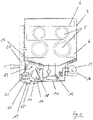
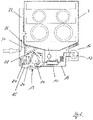
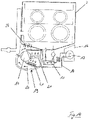
- FIG 15 shows a dishwasher 1 according to the prior art in a schematic front view.
- the dishwasher 1 has a housing 2 which, among other things, accommodates a washing container 3 .
- the rinsing compartment 3 in turn provides a rinsing chamber 4 which, when used as intended, serves to accommodate items to be washed 5 to be cleaned.
- a spray device which is not shown in detail in the figures and is arranged inside the washing container 3 , is used to feed the items to be washed 5 to be cleaned with washing liquor.
- Such a spray device preferably has spray arms, which are each arranged rotatably inside the washing container 3 .
- rinsing baskets 6 are used to hold the washware 5 to be cleaned, with three such rinsing baskets 6 being provided.
- the rinsing chamber 4 opens into a collection pot 7 of the rinsing container 3, not shown in detail, to which a circulating pump 8 is fluidically connected.
- the spray device also not shown in the figures, is fluidically connected to the circulating pump 8 via corresponding supply lines that are not shown in detail in the figures. In the intended use case, the spray device can thus be fed with washing liquor by means of the circulating pump 8 .
- the dishwasher 1 also has a heat pump device 9.
- This has a compressor 10, a condenser 11, an expansion element in the form of a throttle 12, an evaporator 13 and a flow circuit 14 which fluidically connects these structural components with one another and in which a working medium, i.e a refrigerant is guided.
- a working medium i.e a refrigerant is guided.
- the compressor 10 has a refrigerant inlet 17 and a refrigerant outlet 18.
- the heat pump device 9 shown as an example in the figures is a so-called water-water heat pump device, according to which the evaporator 13 is arranged inside a tank 16 that is filled with water as the heat transfer medium.
- the configuration according to the invention explained below is not limited to the design of a heat pump device as a water-water heat pump device. Dishwashers equipped with an air-water heat pump device can also be designed in a manner according to the invention.
- the condenser 11 is used to transfer heat from the refrigerant carried in the flow circuit 14 of the heat pump device 9 to the washing liquor.
- a circulating circuit 15 connected to the circulating pump 8 is provided, which serves to circulate the washing liquor. The heat energy released during operation in the condenser 11 by the liquefaction of the refrigerant is thus transferred to the washing liquor circulated in the circulation circuit 15, for which purpose a correspondingly designed heat exchanger is provided.
- the compressor 10 is connected upstream of the condenser 11, in which the refrigerant present in gaseous form is compressed and thus brought to a higher temperature level.
- the compressor 10 which is, for example, a rotary compressor, heats up.
- the waste heat produced as a result of the heating of the compressor 10 is no longer available for a washing process to be carried out by the dishwasher 1, ie in particular for heating the washing liquor.
- the waste heat from the compressor 10 is at least partially used and recycled to support the heating of the washing liquor. The heat or energy loss associated as a result of the waste heat from the compressor 10 is thus minimized.
- the dishwasher 1 has a heat exchanger 40 assigned to the compressor 10.
- This heat exchanger 40 is fluidically connected to the washing compartment 4.
- the washing liquor coming from the washing container 3 can be routed past the compressor 10 through the heat exchanger 40, which is caused by the in 9 drawn arrows is symbolized.
- the washing liquor guided through the heat exchanger 40 is heated up by the waste heat emitted by the compressor 10 in normal operation.
- the heat exchanger 40 is designed as a pipeline which is fluidically connected to the washing chamber 4 of the washing container 3 .
- the pipeline 40 is arranged in sections on the compressor 10 on the outside of the compressor 10 .
- the pipeline 40 has turns, at least in sections, which, as is shown in particular in the illustration 10 can be seen, extend at least in sections over the outer circumference of the compressor 10.
- the tubing 40 is like this as well 10 can be seen, preferably formed as part of the circulation circuit 15.
- the pipeline 40 is therefore fluidically connected to the circulating pump 8 and is supplied with washing liquor via this.
- the pipeline of the circulation circuit 15 opens directly into the rinsing container 3 after passing through the condenser 11 . According to the invention, it is now provided that this pipeline does not open directly into the rinsing container 3, but instead runs it as a pipeline 40 past the compressor 10 in the manner already described above.
- heat is not only transferred to the washing liquor in the condenser 11 circulating in the circulation circuit 15, but also to the pipe section 40 serving as a heat exchanger 40, which rests on the compressor 10 on the outside.
- the waste heat emitted by the compressor 10 is thus also used to heat the washing liquor circulated in the circulation circuit 15 .
- the efficiency of the heat pump device 9 is thus advantageously increased.
- a latent heat accumulator 26 is provided, which is in operative connection with the heat exchanger 40 .
- the latent heat accumulator 26 is arranged on the washing compartment 3 on the underside of the washing compartment 3 with the interposition of a heat exchanger.
- the pipeline 40 forming the heat exchanger 40 is routed through the latent heat accumulator 26 and opens into the rinsing container 3 in the manner already described above.
- the dishwasher 1 designed according to the invention has a housing 19 within which the compressor 10 is arranged.
- the housing 19 provides an air circulation space 20, so that in the intended use, air can circulate around the compressor 10, as is the case in 1 marked with the arrows shown schematically.
- a fan device 21 which is associated with the air circulation space 20 , is provided to form an air flow around the compressor 10 . while showing 1 an embodiment according to which the fan device 21 is arranged inside the housing 19.
- the blower device 21 ensures that the air contained in the housing 19 circulates. As a result of such air circulation, the compressor 10 is also flushed, so that waste heat emitted by a heated compressor 10 leads to a more even heating of the im Housing 19 located air leads.
- the housing 19 is arranged directly adjacent to the washing compartment 3 and the fresh water inlet system 22, with a heat exchanger 23 or 24 in between, so that heat can be transferred from the heated air in the housing 19 to the washing liquor in the washing compartment 3 and the fresh water in the fresh water inlet system 22 takes place.
- the heat is transferred by convection of the air between the compressor 10 and the rinsing tank 3 or between the compressor 10 and the water inlet system 22.
- the air flow within the housing 19 is generated by the blower device 21, which enables optimized heat transfer between the air and the outer surface of the compressor 10 is.
- the housing 19 has a housing wall which is provided in sections by the washing compartment 3 on the one hand and the fresh water inlet system 22 on the other.
- a double-walled design is dispensed with in the overlapping area between housing 19 and washing container 3 or in the overlapping area between housing 19 and fresh water inlet system 22, which makes the structure according to the invention overall compact and effective in terms of heat transfer.
- the housing wall of the housing 19 is thermally insulated at least in sections, for which purpose the housing wall of the housing 19 is equipped with thermal insulation 25 at least in sections.
- the heat exchangers 23 and 24 formed between the housing 19 and the washing container 3 or between the housing 19 and the fresh water inlet system 22 are preferably each formed in two parts.
- a first part in each case is located outside of the washing container 3 or the fresh water inlet system 22 and has heat-conducting elements that are specially designed for air to flow around.
- the respective second part of the heat exchangers 23 and 24 is arranged within the washing container 3 or the fresh water inlet system 22 and provides heat-conducting elements which are designed in particular with a view to flushing with water.
- heat transfer can take place solely via the housing wall, which connects the housing 19 from the washing compartment 3 or the housing 19 from the fresh water inlet system 22 separates.
- the embodiment after 2 decreases in modification to the embodiment 1 recognize a latent heat accumulator 26 arranged within the housing 19 . This is operatively connected via corresponding heat exchangers 27 and 28 to the air circulated in the housing 19 on the one hand and to the fresh water passed through the fresh water inlet system 22 on the other hand.
- a latent heat accumulator 26 is provided, in a modification to the illustration shown in FIG 2 two heat exchangers 29 and 30 are provided, which are operatively connected on the one hand to the air circulating in the housing 19 and on the other hand to the washing liquor circulating in the washing compartment 3 .
- the latent heat accumulator 26 advantageously serves to intermediately store waste heat given off by the compressor 10 in order to release it again at a later point in time for heating up washing liquor and/or fresh water.
- the latent heat storage device has a storage medium in the form of a hydrate, for example, which is in a liquid state of aggregation after a previous heat input. A conversion of the heat accumulator into a solid state of aggregation as a result of crystallization takes place exothermally, i.e. with the release of heat.
- the compressor 10 When used as intended, the compressor 10 emits heat by radiation and convection to the latent heat store 26, as a result of which frozen liquid is melted, ie liquefied.
- the liquid retains its liquid state in a metastable manner even below the melting temperature and only crystallizes as a result of mechanical stress.
- the heat is given off again.
- the thermal energy can be stored in the latent heat storage device during a first heating-up phase of the washing liquor and released again to the washing liquor during a further subsequent heating-up phase.
- FIG. 1 Another embodiment shows 4 .
- a pipe 31 is provided, which is guided through the housing 19.
- This pipeline is fluidically at the Rinse chamber 4 connected so that in accordance with the in 4 rinsing liquor is guided out of the washing compartment 4 by the arrows drawn in as an example and is guided to the circulation circuit 15 by means of the pipeline 31 .
- the air in the housing 19, which is hot during operation, heats the washing liquor conducted through the pipeline 31, so that heat is transferred from the air in the housing 19 to the washing liquor.
- a heat exchanger 33 which is, for example, simple fins that are arranged on the outside of the pipeline 31 and serve as heat-conducting elements that enable particularly effective heat transfer from the air stored by the housing 19.
- FIG 5 shows one to 4 similar embodiment.
- the pipeline 31 is connected to the circulation circuit 15 both on the rinsing liquor inlet side and on the rinsing liquor outlet side. Consequently, no washing liquor is removed directly from the washing container 3, as is the case in accordance with the embodiment 4 is provided.
- the pipeline 31 can also be guided, at least in sections, in coils that are designed as part of a heat exchanger 32 . In this way, a particularly efficient heat transfer from the air stored by the housing 19 is achieved.
- the housing 19 is fluidically connected to the rinsing chamber 4 .
- an inlet opening 34 opening into the washing compartment 4 and an outlet opening 35 opening out of the washing compartment 4 are provided.
- the air circulated by the blower device 21 can be conveyed out of the housing 19 via the inlet opening 34 into the washing compartment 4 .
- Comparatively cool washing room air is conveyed out of the washing container 3 via the outlet opening 35 in accordance with the amount of air that is conveyed in.
- This air enters the housing 19 via a duct 37, where the air is reheated at the compressor 10.
- An air baffle 38 is provided within the housing 19 in order to avoid a short-circuit flow.
- the hot air introduced into the washing compartment 3 gives off its heat directly to the items to be washed 5 and to the washing liquor in the washing compartment 3 and is Corresponding to the guidance of the channel 37 past the fresh water inlet system 22 back into the housing 19 to the compressor 10, where it absorbs waste heat from the compressor 10 again.
- the inlet opening 34 is covered on the washing container side by means of a splash guard 36 in the exemplary embodiment shown.
- additional flow elements such as air baffles 38 and 39 can be provided, as is shown in FIGS Figs. 7 and 8th reveal.
- Flow elements of this type serve in particular to avoid unwanted short-circuit air flows.
- the embodiment after 7 shows a blower device 21 in the form of a radial air blower, which sucks in the air axially and blows it radially through an air duct with outlet openings.
- the air baffle 38 serves as a partition and provides an airtight seal to the housing 19, which ensures that the air can circulate around the entire compressor 10 as far as possible.
- FIG. 8 shows an embodiment with a fan device 21 designed as an axial fan. Inside this trough, an air flow is forced upwards by the blower. Outside the tub formed in this way, the air is sucked in again, as is the case in 8 symbolize arrows drawn in as an example.
- the air flow generated as a whole can be further optimized by additional flow guide elements, such as ribs or the like.
- a heat exchanger 41 is provided, which is connected upstream of the compressor 10 on the refrigerant side.
- the heat exchanger 41 is a pipeline through which the refrigerant flows, which has windings in sections to increase the heat transfer surface. These windings form the actual heat exchanger 41, also called the superheater.
- the heat exchanger 41 is upstream of the compressor 10 in terms of flow, i.e. it is assigned to the refrigerant inlet side in the compressor 10, so that the refrigerant is heated by means of the heat exchanger 41 before it flows into the compressor 10.
- the heat exchanger 41 is designed as an air heat exchanger, with the refrigerant passed through the heat exchanger 41 in the intended use case being heated by the air surrounding the heat exchanger 41, with this air located in the housing 19 being heated as a result of the waste heat emitted by the compressor 10.
- the compressor waste heat is transferred to the refrigerant by means of the heat exchanger 41, as a result of which the compressor 10 is indirectly cooled.
- the heat transfer takes place with almost no loss if the housing 19 is designed to be thermally insulated from the outside by means of appropriate thermal insulation 25 .
- serving as a superheater heat exchanger 41 is preferably arranged so that free convection occurs due to temperature differences in the air provided by the housing 19 .
- FIG. 13 An alternative embodiment is shown in a schematic side view in 13 shown.
- a pipeline 40 serving as a heat exchanger 40 is provided, which is fluidically connected to the rinsing container 3, as already described above.
- the pipeline 40 in accordance with the in 13 drawn arrows rinsing liquid, that is out rinsing liquor.
- the pipeline 40 is arranged at least in sections on the outside of the compressor 10 .
- the pipeline 40 has a plurality of windings in order to provide the largest possible heat transfer surface between the pipeline 40 and the compressor 10 .
- the heat exchanger 40 serves to heat up the washing liquor conducted through it by the waste heat emitted by the compressor 10 .
- the coolant circulating in the flow circuit 14 is heated in the heat exchanger 41 upstream of the compressor 10 in terms of flow.
- This heat exchanger 41 is a liquid-liquid heat exchanger. This is formed in that the flow circuit 14 is passed at least in sections through the pipe 40, for which purpose the pipe 40 has a larger outside diameter at least in sections. As the 13 can be seen, flow through the heat exchanger 41 in countercurrent, the refrigerant on the one hand and the washing liquor on the other. The washing liquor previously heated in the compressor 10 transfers thermal energy to the coolant carried in the flow circuit 14 .
- the compressor 10 is cooled indirectly via the cold sucked refrigerant, in which the fluid heat exchanger 21 is used, through which the suction line of the flow circuit 14 is guided and through which the cold sucked refrigerant is passed.
- the washing liquor which circulates through the further heat exchanger 40 and absorbs heat from the compressor 10, is cooled down again to its initial temperature in the heat exchanger 41, ie the superheater.
- the compressor 10 is indirectly cooled and at the same time the refrigerant is selectively overheated. Sufficient superheat is necessary to ensure that no liquid refrigerant is drawn through the compressor 10, which could lead to increased wear or total compressor failure.
- FIG. 14 Another embodiment of the configuration according to the invention is in 14 shown.
- the warm air heated by the waste heat from the compressor 10 and circulated by the blower device 21 in the housing 19 serves to heat both the refrigerant in the flow circuit 14 and the washing liquor in the washing container 3 .
- a heat exchanger 24 is provided for this purpose, which is used for heat transfer from the warm air located in the housing 19 to the washing liquor contained in the washing container 3 .
- the heat exchanger 41 that is to say the superheater, however, serves to transfer heat energy from the circulated hot air from the flow circuit 14 to the refrigerant carried.
- the embodiment after 14 proves against the embodiment 12 than more effective, because not only does the refrigerant heat up, but the washing liquor also heats up at the same time.
Landscapes
- Washing And Drying Of Tableware (AREA)
Abstract
Description
- Die Erfindung betrifft eine Geschirrspülmaschine, insbesondere eine Haushaltsgeschirrspülmaschine, mit einem einen Spülraum bereitstellenden Spülbehälter, der der Aufnahme von zu reinigendem Spülgut dient, und einer Wärmepumpeneinrichtung, die einen Verdichter mit einem Kältemitteleingang und einem Kältemittelausgang aufweist.
- Geschirrspülmaschinen der eingangs genannten Art sind aus dem Stand der Technik an sich wohl bekannt, weshalb es eines gesonderten druckschriftlichen Nachweises an dieser Stelle nicht bedarf.
- Vorbekannte Geschirrspülmaschinen verfügen über einen Spülbehälter, auch Bottich genannt, der einen Spülraum bereitstellt. Dieser ist verwenderseitig über eine Beschickungsöffnung zugänglich, die mittels einer verschwenkbar gelagerten Spülraumtür fluiddicht verschließbar ist. Im bestimmungsgemäßen Verwendungsfall dient der Spülbehälter zur Aufnahme von zu reinigendem Spülgut, bei dem es sich beispielsweise um Geschirr, Besteckteile und/oder dergleichen handeln kann.
- Zur Beaufschlagung von zu reinigendem Spülgut mit Spülflüssigkeit, der sog. Spülflotte, verfügt die Geschirrspülmaschine im Innenraum des Spülbehälters über eine Sprüheinrichtung. Diese Sprüheinrichtung stellt typischerweise verdrehbar gelagerte Sprüharme zur Verfügung, wobei in der Regel zwei oder drei solcher Sprüharme vorgesehen sind. Im bestimmungsgemäßen Verwendungsfall erfolgt eine Beaufschlagung des zu reinigenden Spülguts mit Spülflotte mittels sich drehender Sprüharme.
- Die von der Sprüheinrichtung im Betriebsfall abgegebene Spülflotte trifft auf das zu reinigende Spülgut und sammelt sich alsdann in einem Sammeltopf des Spülbehälters an. Der Sammeltopf ist an eine Umwälzpumpe einerseits und an eine Ablaufpumpe andererseits angeschlossen. Zur Beaufschlagung der Sprüheinrichtung mit Spülflotte dient die Umwälzpumpe, die im bestimmungsgemäßen Verwendungsfall die in die Geschirrspülmaschine eingeförderte Spülflüssigkeit umwälzt. Mit Abschluss eines Spülprogramms wird die Spülflotte mittels der Ablaufpumpe abgepumpt und verworfen.
- Geschirrspülmaschinen der eingangs genannten Art können bekanntermaßen mit einer Wärmepumpeneinrichtung ausgestattet sein, um den Energieverbrauch insbesondere bei einem Aufheizen der Spülflotte zu reduzieren, insbesondere deshalb, weil ein solches Aufheizen der Spülflotte den größten Anteil am Energieverbrauch einer Geschirrspülmaschine ausmacht.
- Aus der
EP 2 682 038 A2 ist eine Geschirrspülmaschine mit einer Luft-Wasser-Wärmepumpeneinrichtung bekannt. Im Betriebsfall entzieht die Wärmepumpeneinrichtung der Umgebungsatmosphäre, das heißt der die Geschirrspülmaschine umgebenden Luft Wärmeenergie, um diese auf die im Inneren der Geschirrspülmaschine umgewälzte Spülflotte zu übertragen. Die Wärmepumpeneinrichtung verfügt zu diesem Zweck in an sich bekannter Weise über einen Verdampfer, einen Verdichter, einen Verflüssiger und einen diese Komponenten miteinander strömungstechnisch verbindenden Strömungs- oder Umwälzkreislauf. Dabei dient der Verflüssiger als Wärmetauscher, mittels dem Wärmeenergie von einem im Strömungskreislauf der Wärmepumpeneinrichtung umgewälzten Kältemittel auf die Spülflotte übertragen wird. - Im bestimmungsgemäßen Verwendungsfall der Wärmepumpeneinrichtung wird zwecks Aufheizung der Spülflotte mittels Ventilatoren Raumluft angesaugt und über den Verdampfer der Wärmepumpeneinrichtung geleitet. Dies führt zu einer Abkühlung der zugeführten Raumluft, wobei die der Raumluft entzogene Wärmeenergie auf das Kältemittel übertragen wird, das infolge dessen im Verdampfer verdampft.
- Das daraufhin in gasförmiger Form vorliegende Kältemittel wird anschließend in dem Verdichter komprimiert und so auf ein höheres Temperaturniveau gebracht. Der Verdichter verfügt zu diesem Zweck über einen Kältemitteleingang und einen Kältemittelausgang, wobei das noch nicht komprimierte Kältemittel dem Verdichter über den Kältemitteleingang zugeführt wird, wohingegen das im Verdichter komprimierte Kältemittel den Verdichter über den Kältemittelausgang verlässt. Schließlich erfolgt eine Einleitung des gasförmigen und komprimierten Kältemittels in den Verflüssiger, wo unter Energiefreigabe eine Verflüssigung des Kältemittels stattfindet. Die dabei frei werdende Wärmeenergie dient der Spülflottenaufheizung.
- Aus dem Stand der Technik ist gleichfalls der Einsatz von Wasser-Wasser-Wärmepumpeneinrichtungen bekannt, so zum Beispiel aus der
EP 2 206 824 A2 . Im bestimmungsgemäßen Verwendungsfall wird mit einer solchen Wärmepumpeneinrichtung nicht der Umgebungsatmosphäre, sondern einem Flüssigkeitsreservoir Wärmeenergie entzogen. DieEP 2 206 824 A2 sieht zu diesem Zweck einen geschlossenen Wassertank vor, der den Verdampfer der Wärmepumpeneinrichtung beherbergt. Im Betriebsfall kommt es infolge eines Wärmeenergieentzugs zu einer Abkühlung des im Tank bevorrateten Wassers. Dabei kann eine Abkühlung des Wassers bis zur Vereisung vorgenommen werden. - Den vorbekannten Konstruktionen ist gemein, dass sich der Verdichter im bestimmungsgemäßen Verwendungsfall aufheizt, wobei die insoweit verbrauchte Aufheizenergie einem von der Geschirrspülmaschine durchgeführten Spülprogramm als Verlustenergie nicht zur Verfügung steht. Dieser Nachteil kommt insbesondere bei als Rollkolbenverdichter ausgebildeten Verdichtern zum Tragen, die bei Geschirrspülmaschinen aufgrund ihrer kompakten und robusten Bauform typischerweise zum Einsatz kommen. So stoßen Rollkolbenverdichter konzeptbedingt das verdichtete, gasförmige und heiße Kältemittel in das eigene Gehäuse aus. Infolge dessen kommt es zur Aufheizung des Rollkolbenverdichters bis auf eine Temperatur, die das Kältemittel infolge seiner Verdichtung im Verdichter annimmt. Es können so Temperaturen an der Oberfläche des Rollkolbenverdichters von bis zu 100° C entstehen, was zu erhöhten Wärmeverlusten durch Strahlungswärme und freie Konvektion führt. Ein Großteil dieser Abwärme wird auf andere Komponenten der Geschirrspülmaschine, auf zur Geschirrspülmaschine benachbarte Möbel und/oder den Aufstellungsuntergrund der Geschirrspülmaschine übertragen und bleibt somit vom eigentlichen Spülprozess ungenutzt.
- Es ist ausgehend vom Vorbeschriebenen die Aufgabe der Erfindung, eine Geschirrspülmaschine der eingangs genannten Art dahingehend weiterzuentwickeln, dass die infolge einer bestimmungsgemäßen Nutzung der Wärmepumpeneinrichtung am Verdichter entstehenden Wärmeverluste konstruktiv minimiert sind.
- Zur Lösung dieser Aufgabe wird mit der Erfindung gemäß einer ersten Ausführungsform eine Geschirrspülmaschine der eingangs genannten Art vorgeschlagen, die sich dadurch auszeichnet, dass dem Verdichter ein Wärmetauscher zugeordnet ist, der mit dem Spülraum in strömungstechnischer Verbindung steht.
- Der Verdichter ist erfindungsgemäß mit einem Wärmetauscher wirkgekoppelt, wobei der Wärmetauscher seinerseits mit dem Spülraum in strömungstechnischer Verbindung steht. Dabei gestattet es die strömungstechnische Verbindung des Wärmetauschers mit dem Spülraum, dass durch den Wärmetauscher aus dem Spülraum stammende Spülflotte geführt werden kann. Aufgrund der Zuordnung des Verdichters zum Wärmetauscher kann so vom Verdichter stammende Abwärme auf die Spülflotte direkt übertragen werden. Die erfindungsgemäße Ausgestaltung gestattet es mithin, die vom Verdichter im bestimmungsgemäßen Verwendungsfall der Wärmepumpeneinrichtung erzeugte Abwärme zur wunschgemäßen Aufheizung der Spülflotte zu nutzen.
- Dabei muss der erfindungsgemäß vorgesehene Wärmetauscher nicht am Spülraum befestigt sein. Es ist eine Anordnung des Wärmetauschers auch am Verdichter möglich, was aus Gründen der vereinfachten Montage bevorzugt ist. Dabei ist der Wärmetauscher zumindest spülflotteneingangsseitig vorzugsweise schaltbar ausgebildet, das heißt eine Beschickung des Wärmetauschers mit Spülflotte findet nur dann statt, wenn der Verdichter nutzbare Abwärme zur Verfügung stellt. Andernfalls bleibt der Wärmetauscher von Spülflotte undurchströmt.
- Der Wärmetauscher ist gemäß einem weiteren Merkmal der Erfindung eine strömungstechnisch an den Spülraum angeschlossene Rohrleitung, der abschnittsweise außenseitig des Verdichters am Verdichter angeordnet ist. Dabei kann die Rohrleitung zumindest abschnittsweise Rohrwindungen aufweisen. Diese Rohrwinden umgreifen den Verdichter außenseitig zumindest teilweise, so dass insgesamt eine möglichst große Wärmeaustauscherfläche bereitgestellt ist.
- Der Wärmetauscher ist gemäß einer ersten Ausführungsform an einen separaten Wasserkreislauf angeschlossen bzw. bildet einen eigenen Wasserkreislauf aus, welcher parallel zum Hauptkreislauf durch die Umwälzpumpe gespeist ist. Alternativ hierzu kann der Wärmetauscher auch so ausgeführt sein, dass er am Spülbehälter angeordnet ist, wobei innerhalb des Spülbehälters eine trichterförmige Spülflottenzuführung vorgesehen ist, in welcher sich die Spülflotte staut, bevor sie durch den Wärmetauscher hindurch der Schwerkraft folgend zu einem tiefer gelegenen Bereich des Spülbehälters abfließt. Diese Ausgestaltung hat den Vorteil, dass kein zusätzlicher Spülflottenkreislauf parallel zum Hauptspülflottenkreislauf besteht, welcher durch die Umwälzpumpe betrieben wird. Somit wird kein zusätzlicher Druckabfall erzeugt.
- Gemäß einem weiteren Merkmal der Erfindung ist vorgesehen, dass der Wärmetauscher in Wirkverbindung mit einem Latentwärmespeicher steht. Während eines bestimmungsgemäßen Betriebs des Verdichters gibt dieser Wärme durch Strahlung und Konvektion an den Latentwärmespeicher ab, dessen eingefrorene Flüssigkeit hierdurch aufgeschmolzen wird. Diese Flüssigkeit, bei der es sich beispielsweise um ein Hydrat handelt, behält ihren flüssigen Aggregatzustand metastabil auch unterhalb der Schmelztemperatur bei und kristallisiert bei leichter mechanischer Belastung exotherm aus. Die insoweit entstehende Wärme wird in schon vorbeschriebener Weise durch die durch den Wärmetauscher hindurchgeführte Spülflotte übertragen.
- Die Wärmeenergie kann während einer ersten Aufheizphase der Spülflotte im Latentwärmespeicher gespeichert werden und während einer weiteren nachgelagerten Aufheizphase, wie zum Beispiel dem Klarspülen wieder an die Spülflotte abgegeben werden. Die Schmelztemperatur der Flüssigkeit im Latentwärmespeicher liegt in einem Bereich zwischen 30° C und 70° C, bevorzugt zwischen 40° C und 60° C. In diesem Temperaturbereich ist sichergestellt, dass die Flüssigkeit während der Aufheizphase vollständigt verflüssigt und so die Energie dauerhaft speichert.
- Die Aktivierung der Kristallisation der Flüssigkeit erfolgt von außerhalb mechanisch über einen Aktor, welcher zum Beispiel ein Metallplättchen innerhalb der Flüssigkeit verformt. Hierbei kann zum Beispiel ein Stößel elektromechanisch bewegt werden, welcher von einem Faltenbalg umschlossen ist. Letzterer dichtet gleichzeitig gegenüber dem Behälter des Latentwärmespeichers ab, in welchem die Flüssigkeit gelagert ist. Alternativ kann der Latentwärmespeicher auch durch eine Membran aktiviert werden, welche sich durch Wasserdruck verformt und so die Kristallisation auslöst. Dies kann beispielsweise dadurch geschehen, dass Spülflotte in einer Rohrschlange an der Membran vorbeigeleitet wird. Bei Druckbeaufschlagung verformt sich die Membran und löst die Kristallisation aus. Somit wird die Wärme erst dann abgegeben, wenn die Spülflotte durch die vorzugsweise als Wärmetauscher fungierende Rohrschlange geleitet wird. Dieser parallele Kreislauf kann zum Beispiel durch ein Magnetventil geschaltet werden. Diese Lösung bietet den Vorteil, dass die Wärmeübertragung und die Kristallisation zeitgleich ausgelöst werden, wodurch die Wärmeenergie optimiert vom Wärmespeicher auf die Spülflotte übertragen wird.
- Der Wärmeeintrag in den Latentwärmespeicher bzw. der Wärmeaustrag aus dem Latentwärmespeicher kann weiter dadurch optimiert werden, dass gemäß einem weiteren Merkmal der Erfindung vorgesehen ist, dass der Latentwärmespeicher außenseitig am Spülbehälter und/oder einem Frischwassereinlauf angeordnet ist. Es ist mithin gemäß dieser Ausführungsform eine direkte Nebenordnung des Latentwärmespeichers zum Spülbehälter bzw. zum Frischwassereinlaufsystem vorgesehen. Dabei kann eine solche direkte Nebenordnung unter Zwischenordnung eines Wärmespeichers vorgesehen sein, wie vorstehend bereits erläutert.
- Der Verdichter ist vorzugsweise unterhalb des Spülbehälters innerhalb eines Gehäuses angeordnet. Dabei ist das Gehäuse derart dimensioniert, dass es einen Luftzirkulationsraum bereitstellt, so dass Luft um den Verdichter herum zirkulieren kann. Dabei ist das Gehäuse möglichst geschlossen, das heißt im Wesentlichen luftdicht ausgebildet. Dabei meint "im Wesentlichen luftdicht" nicht hermetisch abgedichtet. Die geschlossene Ausgestaltung des Gehäuses soll lediglich sicherstellen, dass im Luftzirkulationsraum befindliche und von der Abwärme des Verdichters erwärmte Luft nicht ungewollt in die das Gehäuse umgebende Atmosphäre entweicht.
- Dem Luftzirkulationsraum ist erfindungsgemäß eine Gebläseeinrichtung zugeordnet. Diese sorgt im bestimmungsgemäßen Verwendungsfall für eine Luftzirkulation innerhalb des Gehäuses, so dass der Verdichter luftumspült ist. Es kann so eine gleichmäßige Erwärmung der im Gehäuseinneren befindlichen Luft durch die vom Verdichter im Betriebsfall erzeugte Abwärme erreicht werden.
- Die vom Gehäuse beherbergte und im Betriebsfall von der Abwärme des Verdichters erwärmte Luft kann in vorteilhafter Weise zur direkten oder indirekten Aufheizung von im Spülbehälter befindlicher Spülflotte genutzt werden. Somit wird zumindest ein Teil der Verdichterabwärme für die Spülflottenaufheizung nutzbar, wodurch der infolge einer Nutzung der Wärmepumpeneinrichtung unvermeidbar entstehende Wärmeverlust minimiert ist. Dabei erfolgt die Wärmeübertragung durch Konvektion der im Gehäuseinneren befindlichen Luft zwischen Verdichter und Spülbehälter und/oder zwischen Verdichter und einem Frischwassereinlaufsystem. Der im Gehäuseinneren insoweit zirkulierende Luftstrom wird mechanisch mittels der Gebläseeinrichtung erzeugt, was eine optimierte Wärmeübertragung zwischen Luft und Verdichteroberfläche ermöglicht. Ein Wärmeübertrag auf die im Spülbehälter befindliche Spülflotte erfolgt dabei entweder direkt mittels entsprechender Wärmetauscher oder indirekt durch einen Latentwärmespeicher. Dabei hat der Latentwärmespeicher den Vorteil,
- Verdichterabwärme auch zu einem späteren Zeitpunkt nutzbar zu machen.
- Die für die Ausbildung und Aufrechterhaltung einer Luftzirkulation vorgesehene Gebläseeinrichtung ist gemäß einem weiteren Merkmal der Erfindung innerhalb des Gehäuses angeordnet. Es ist so eine kompakte und gegenüber äußeren mechanischen Einflüssen geschützte Bauform gegeben. Dabei ist die Gebläseeinrichtung bevorzugterweise drehzahlgeregelt ausgeführt, so dass der von ihr erzeugte Luftstrom abhängig von der Verdichtertemperatur oder der sich einstellenden Lufttemperatur oder der sich einstellenden Spülflottentemperatur geregelt werden kann. Dazu wird mindestens eine dieser Temperaturen fortwährend gemessen. Die Erfassung der Lufttemperatur erfolgt vorzugsweise an zwei voneinander unabhängigen Messstellen, um auch die Wärmeleistung der im Luftstrom befindlichen Wärmeübertrager zu erfassen. Die Gebläseeinrichtung wird insbesondere derart geregelt, dass die Lufttemperatur innerhalb des Luftzirkulationsraumes während eines Aufheizvorgangs innerhalb eines Spülprogramms zumindest zeitweise, vorzugsweise zumindest nahezu während des gesamten Aufheizvorgangs im Bereich unterhalb der Oberflächentemperatur des Verdichters und oberhalb der Temperatur der Spülflotte liegt und/oder- in einem Bereich zwischen 50°C und 80°C.
- Gemäß einem weiteren Merkmal der Erfindung ist vorgesehen, dass das Gehäuse benachbart zum Spülbehälter und/oder zu einem Frischwassereinlaufsystem ausgebildet ist. Der Wärmeübertragungsweg ist so möglichst kurz ausgefüllt, womit unnötige Wärmeübertragungsverluste vermieden sind. Gemäß einer besonders einfachen und zugleich effektiven Bauform ist vorgesehen, dass das Gehäuse eine Gehäusewandung aufweist, die abschnittsweise vom Spülbehälter und/oder vom Frischwassereinlaufsystem bereitgestellt ist. Es ist insofern keine doppelwandige Ausgestaltung vorgesehen. Vielmehr dient die vom Spülbehälter und/oder dem Frischwassereinlaufsystem ohnehin schon zur Verfügung gestellte Wand zugleich auch dem Gehäuse zumindest abschnittsweise als Gehäusewandung. Es kann so über die gemeinsame Gehäusewandung ein direkter Wärmeübertrag von der durch die Verdichterabwärme aufgeheizten Luft auf die im Spülbehälter befindliche Spülflotte und/oder auf im Frischwassereinlaufsystem geführtes Frischwasser stattfinden.
- Gemäß einem weiteren Merkmal der Erfindung ist vorgesehen, dass die Gehäusewandung abschnittsweise wärmeisoliert ausgebildet ist. Dabei sind bevorzugterweise diejenigen Abschnitte der Gehäusewandung wärmeisoliert ausgebildet, die nicht in Wärmeübertragungskontakt mit dem Spülbehälter und/oder dem Frischwassereinlaufsystem stehen. Auf diese Weise ist sichergestellt, dass über am Wärmeaustausch nicht beteiligte Gehäusewandungen ungewollt Wärme an die das Gehäuse umgebende Atmosphäre abgegeben wird.
- Zwischen dem Gehäuse und dem Spülbehälter und/oder zwischen dem Gehäuse und dem Frischwassereinlaufsystem ist gemäß einem weiteren Merkmal der Erfindung bevorzugterweise ein Wärmetauscher ausgebildet. Die Effektivität der Wärmeübertragung wird hierdurch noch einmal gesteigert. Mittels der Wärmetauscher findet eine direkte Übertragung der Wärmeenergie der heißen Luft auf die Spülflotte bzw. auf das Frischwasser statt. Die Wärmetauscher sind vorzugsweise jeweils zweigeteilt ausgebildet. Der jeweils eine Teil befindet sich außerhalb des Spülbehälters bzw. des Frischwassereinlaufsystems und hat wärmeleitende Elemente speziell für die Luftströmung. Der jeweils zweite Teil ist innerhalb des Spülbehälters bzw. innerhalb des Frischwassereinlaufsystems angeordnet und hat wärmeleitende Elemente speziell für Wasser.
- Der zwischen Gehäuse und Frischwassereinlaufsystem ausgebildete Wärmetauscher kann auch einteilig ausgebildet sein, beispielsweise dadurch, dass ein oder mehrere Bleche aus Metall in Form von Lamellen in die entsprechende wasserführende Komponente integriert sind. Dabei besteht die wasserführende Komponente typischerweise aus Kunststoff, so dass entsprechend gestaltete Metalleinleger denkbar sind, welche mit Kunststoff im 2-Komponenten-Verfahren umspritzt werden und im bestimmungsgemäßen Verwendungsfall der Geschirrspülmaschine als Wärmetauscher fungieren.
- Alternativ oder in Kombination zu einer direkten Wärmeübertragung erfolgt eine indirekte Wärmeübertragung, zu welchem Zweck gemäß einem weiteren Merkmal der Erfindung innerhalb des Gehäuses ein Latentwärmespeicher angeordnet ist, der mit dem Spülbehälter und/oder dem Frischwassereinlaufsystem in Wirkverbindung steht.
- Gemäß einem weiteren Merkmal der Erfindung ist vorgesehen, dass innerhalb des Gehäuses ein Luftleitblech angeordnet ist.
- Das Luftleitblech dient der konstruktiven Bereitstellung eines strömungsoptimierten Luftzirkulationsraums. Dabei sorgt das Luftleitblech insbesondere dafür, dass kein Kurzschlussluftstrom der Luft durch die Gebläseeinrichtung entsteht und die Luft möglichst um den gesamten Verdichter herumgeleitet wird. Es können ein Luftleitblech oder mehrere Luftleitbleche vorgesehen sein, die insbesondere in Abhängigkeit der Ausgestaltung der Gebläseeinrichtung ausgebildet sind. Dabei können als Gebläseeinrichtung ein Radialluftgebläse oder ein Axialluftgebläse vorgesehen sein. Ferner können für die Ausbildung einer optimierten Luftzirkulation weitere Luftleitelemente wie zum Beispiel Rippen vorgesehen sein, beispielsweise außenseitig des Verdichters und/oder innenseitig der Innenwandung des den Verdichter aufnehmenden Gehäuses.
- Gemäß einer weiteren Ausführungsform der Erfindung oder zusätzlich zu den Merkmalen der vorgenannten Ausführungsformen ist vorgesehen, dass dem Verdichter kältemitteleingangsseitig ein Wärmetauscher vorgeschaltet ist, wobei der Verdichter und der Wärmetauscher innerhalb des den Luftzirkulationsraum bereitstellenden Gehäuses angeordnet sind.
- Die vom Gehäuse beherbergte und im Betriebsfall von der Abwärme des Verdichters erwärmte Luft kann in vorteilhafter Weise zur Aufheizung von im Kältemittelkreislauf der Wärmepumpeneinrichtung geführten Kältemittel genutzt werden.
- Zur Wärmeübertragung auf das Kältemittel ist ein Wärmetauscher, auch Überhitzer genannt, vorgesehen, der dem Verdichter in Zirkulationsrichtung des Kältemittels strömungstechnisch vorgeschaltet ist. Dieser Wärmetauscher ist mithin dem Verdichter kältemitteleingangsseitig vorgeschaltet, das heißt im Kältemittelkreislauf der Wärmepumpeneinrichtung zirkulierendes Kältemittel gelangt unter strömungstechnischer Zwischenschaltung des Wärmetauschers, das heißt des Überhitzers zum Verdichter.
- Die Wärmeübertragung auf das im Kältemittelkreislauf geführte Kältemittel erfolgt durch Konvektion der im Gehäuseinneren befindlichen Luft zwischen Verdichter und Wärmetauscher. Dabei wird der im Gehäuseinneren insoweit zirkulierende Luftstrom mechanisch mittels der Gebläseeinrichtung erzeugt, was eine optimierte Wärmeübertragung zwischen Luft und Verdichteroberfläche ermöglicht.
- Im bestimmungsgemäßen Verwendungsfall wird das dem Verdichter zuzuführende
- Kältemittel vor einem Einströmen in den Verdichter vorgewärmt. Zu diesem Zweck wird die Verdichterabwärme mittels des Wärmetauschers auf das Kältemittel übertragen, was zu einer indirekten Kühlung des Verdichters führt. Der Wärmeübergang erfolgt dabei nahezu verlustfrei, wenn der Wärmetauscher innerhalb des Gehäuses so angeordnet ist, dass sich eine freie Konvektion aufgrund von Temperaturunterschieden der vom Gehäuse beherbergten Luft einstellt. Zur weiteren Optimierung kann das den Verdichter und den Wärmetauscher beherbergende Gehäuse wärmeisoliert ausgebildet sein, so dass ein ungewollter Wärmeaustrag in die das Gehäuse umgebende Atmosphäre unterbunden ist.
- Gemäß einem weiteren Merkmal der Erfindung ist vorgesehen, dass der Wärmetauscher im einfachsten Ausführungsfall eine vom Kältemittel durchströmte Rohrleitung ist. Diese Rohrleitung ist innerhalb des Gehäuses verlegt, so dass ein Wärmeübertrag von der im Gehäuse befindlichen warmen Luft auf die Rohrleitung und damit auf das durch die Rohrleitung hindurchgeführte Kältemittel stattfinden kann.
- Die Rohrleitung weist bevorzugterweise zumindest abschnittsweise eine Mehrzahl von Windungen auf. Damit wird die insgesamt zur Verfügung stehende Wärmekontaktübertragungsfläche erhöht, was einen gesteigerten Wärmeeintrag in das Kältemittel gestattet.
- Zur Lösung der Aufgabe werden darüber hinaus auch noch folgende Ausführungsbeispiele einer Geschirrspülmaschine vorgeschlagen:
- Ausführung 1:
Geschirrspülmaschine, insbesondere Haushaltsgeschirrspülmaschine, mit einem einen Spülraum bereitstellenden Spülbehälter, der der Aufnahme von zu reinigendem Spülgut dient, und einer Wärmepumpeneinrichtung, die einen Verdichter mit einem Kältemitteleingang und einem Kältemittelausgang aufweist, wobei dem Verdichter kältemitteleingangsseitig ein Wärmetauscher vorgeschaltet ist, wobei der Wärmetauscher in Wirkkontakt mit der im Betriebsfall des Verdichters vom Verdichter erzeugten Verdichterabwärme steht. - Ausführung 2:
Geschirrspülmaschine nach Ausführung 1, wobei der Verdichter und der Wärmetauscher innerhalb eines einen Luftzirkulationsraum bereitstellenden Gehäuses angeordnet sind. - Ausführung 3:
Geschirrspülmaschine nach einer der Ausführungen 1 oder 2, wobei der Wärmetauscher eine vom Kältemittel durchströmte, vorzugsweise eine Mehrzahl von Windungen aufweisende und/oder Lamellen tragende, Rohrleitung ist. - Ausführung 4:
Geschirrspülmaschine nach einer der Ausführungen 1 bis 3, wobei dem Verdichter ein Wärmetauscher zugeordnet ist, der mit dem Spülraum in strömungstechnischer Verbindung steht.. - Ausführung 5:
Geschirrspülmaschine nach Ausführung 4, wobei der Wärmetauscher eine strömungstechnisch an den Spülraum angeschlossene Rohrleitung ist, die abschnittsweise außenseitig des Verdichters am Verdichter angeordnet ist. - Ausführung 6:
Geschirrspülmaschine nach einem der Ausführungen 1 bis 5, wobei die das Kältemittel führende Rohrleitung zumindest abschnittsweise von der an den Spülraum strömungstechnisch angeschlossenen Rohrleitung aufgenommen ist. - Weitere Merkmale und Vorteile der Erfindung ergeben sich aus der nachfolgenden Beschreibung anhand der Figuren.
-
Figur 15 lässt in schematischer Frontansicht eine Geschirrspülmaschine 1 nach dem Stand der Technik erkennen. Die Geschirrspülmaschine 1 verfügt über ein Gehäuse 2, das unter anderem einen Spülbehälter 3 aufnimmt. Der Spülbehälter 3 stellt seinerseits einen Spülraum 4 bereit, der im bestimmungsgemäßen Verwendungsfall der Aufnahme von zu reinigendem Spülgut 5 dient. - Zur Beschickung von zu reinigendem Spülgut 5 mit Spülflotte dient eine in den Figuren nicht näher dargestellte Sprüheinrichtung, die innerhalb des Spülbehälters 3 angeordnet ist. Bevorzugterweise verfügt eine solche Sprüheinrichtung über Sprüharme, die jeweils verdrehbar innerhalb des Spülbehälters 3 angeordnet sind.
- Im gezeigten Ausführungsbeispiel dienen zur Aufnahme des zu reinigenden Spülguts 5 Spülkörbe 6, wobei drei solcher Spülkörber 6 vorgesehen sind.
- Der Spülraum 4 mündet in einen im Detail nicht näher dargestellten Sammeltopf 7 des Spülbehälters 3 ein, an den eine Umwälzpumpe 8 strömungstechnisch angeschlossen ist. Über entsprechende und in den Figuren nicht näher dargestellte Versorgungsleitungen ist die in den Figuren ebenfalls nicht dargestellte Sprüheinrichtung an die Umwälzpumpe 8 strömungstechnisch angeschlossen. Im bestimmungsgemäßen Verwendungsfall kann damit eine Beschickung der Sprüheinrichtung mit Spülflotte mittels der Umwälzpumpe 8 stattfinden.
- Die Geschirrspülmaschine 1 verfügt des Weiteren über eine Wärmepumpeneinrichtung 9. Diese weist einen Verdichter 10, einen Verflüssiger 11, ein Expansionsorgan in Form einer Drossel 12, einen Verdampfer 13 sowie einen diese Baukomponenten strömungstechnisch miteinander verbindenden Strömungskreislauf 14 auf, in dem ein Arbeitsmedium, das heißt ein Kältemittel geführt ist. Zum Anschluss des Verdichters 10 an den Strömungskreislauf 14 verfügt der Verdichter 10 über einen Kältemitteleingang 17 und einen Kältemittelausgang 18.
- Die in den Figuren beispielhaft dargestellte Wärmepumpeneinrichtung 9 ist eine sog. Wasser-Wasser-Wärmepumpeneinrichtung, dergemäß der Verdampfer 13 innerhalb eines Tanks 16 angeordnet ist, der mit Wasser als Wärmeträgermedium befüllt ist. Die im Weiteren erläuterte erfindungsgemäße Ausgestaltung ist auf die Ausbildung einer Wärmepumpeneinrichtung als Wasser-Wasser-Wärmepumpeneinrichtung nicht beschränkt. Auch mit einer Luft-Wasser-Wärmepumpeneinrichtung ausgerüstete Geschirrspülmaschinen können in erfindungsgemäßer Weise ausgebildet sein.
- Im bestimmungsgemäßen Verwendungsfall der Wärmepumpeneinrichtung 9 findet mit Hilfe des Verflüssigers 11 ein Wärmeübertrag von dem im Strömungskreislauf 14 der Wärmepumpeneinrichtung 9 geführten Kältemittel auf die Spülflotte statt. Zu diesem Zweck ist ein an die Umwälzpumpe 8 angeschlossener Umwälzkreislauf 15 vorgesehen, der der Spülflottenumwälzung dient. Die im Betriebsfall im Verflüssiger 11 durch Verflüssigung des Kältemittels frei werdende Wärmeenergie wird mithin auf die im Umwälzkreislauf 15 umgewälzte Spülflotte übertragen, zu welchem Zweck ein entsprechend ausgebildeter Wärmetauscher vorgesehen ist.
- Dem Verflüssiger 11 ist strömungstechnisch der Verdichter 10 vorgeschaltet, in dem das in gasförmiger Form vorliegende Kältemittel komprimiert und so auf ein höheres Temperaturniveau gebracht wird. Infolge einer solchen Kältemittelkomprimierung erwärmt sich der Verdichter 10, bei dem es sich beispielsweise um einen Rollkolbenverdichter handelt. Die infolge der Erwärmung des Verdichters 10 entstehende Abwärme steht für einen von der Geschirrspülmaschine 1 durchzuführenden Spülprozess, das heißt insbesondere für eine Aufheizung der Spülflotte nicht mehr zur Verfügung. Mittels der erfindungsgemäßen Ausgestaltung, wie sie in verschiedenen Ausführungsformen in den
Figuren 1 bis 14 gezeigt ist, wird die Abwärme des Verdichters 10 zumindest teilweise genutzt und zur Unterstützung der Aufwärmung der Spülflotte rückgeführt. Damit ist der infolge der Abwärme des Verdichters 10 einhergehende Wärme- bzw. Energieverlust minimiert. - Wie die Ausführungsform nach
Fig. 9 erkennen lässt, verfügt die Geschirrspülmaschine 1 über einen dem Verdichter 10 zugeordneten Wärmetauscher 40. Dieser Wärmetauscher 40 steht mit dem Spülraum 4 in strömungstechnischer Verbindung. Im bestimmungsgemäßen Verwendungsfall kann durch den Wärmetauscher 40 aus dem Spülbehälter 3 stammende Spülflotte am Verdichter 10 vorbeigeführt werden, was durch die inFig. 9 eingezeichneten Pfeile symbolisiert ist. Infolge eines solchen Vorbeiführens der Spülflotte am Verdichter 10 erfolgt ein Aufheizen der durch den Wärmetauscher 40 hindurchgeführten Spülflotte durch die vom Verdichter 10 im bestimmungsgemäßen Betriebsfall ausgehende Abwärme. - Gemäß dem gezeigten Ausführungsbeispiel nach
Fig. 9 ist der Wärmetauscher 40 als Rohrleitung ausgebildet, die an den Spülraum 4 des Spülbehälters 3 strömungstechnisch angeschlossen ist. Dabei ist die Rohrleitung 40 abschnittsweise außenseitig des Verdichters 10 am Verdichter 10 angeordnet. Um einen möglichst optimierten Wärmeübergang vom Verdichter 10 auf die durch die Rohrleitung 40 hindurchgeführte Spülflotte zu erreichen, weist die Rohrleitung 40 zumindest abschnittsweise Windungen auf, die, wie dies insbesondere die Darstellung nachFig. 10 erkennen lässt, sich zumindest abschnittsweise über den Außenumfang des Verdichters 10 erstrecken. - Die Rohrleitung 40 ist, wie dies ebenfalls
Fig. 10 erkennen lässt, bevorzugterweise als Teil des Umwälzkreislaufes 15 ausgebildet. Die Rohrleitung 40 ist mithin an die Umwälzpumpe 8 strömungstechnisch angeschlossen und wird über diese mit Spülflotte versorgt. Wie ein Vergleich der Darstellung nachFig. 10 mit dem Stand der Technik nachFig. 15 erkennen lässt, mündet gemäß dem Stand der Technik die Rohrleitung des Umwälzkreislaufes 15 nach einem Passieren des Verflüssigers 11 direkt in den Spülbehälter 3 ein. Erfindungsgemäß ist nun vorgesehen, diese Rohrleitung nicht direkt in den Spülbehälter 3 einmünden zu lassen, sondern diese vielmehr als Rohrleitung 40 in schon vorbeschriebener Weise am Verdichter 10 vorbeizuführen. Damit erfolgt bei der erfindungsgemäßen Ausgestaltung nicht nur ein Wärmeübergang auf die im Umwälzkreislauf 15 geführte Spülflotte im Verflüssiger 11, sondern auch in dem als Wärmetauscher 40 dienenden Rohrabschnitt 40, der außenseitig am Verdichter 10 anliegt. Damit wird auch die vom Verdichter 10 ausgehende Abwärme genutzt, um die im Umwälzkreislauf 15 umgewälzte Spülflotte zu erwärmen. Der Wirkungsgrad der Wärmepumpeneinrichtung 9 wird damit in vorteilhafter Weise erhöht. - Gemäß einer weiteren Ausführungsform der Erfindung, die in
Fig. 11 gezeigt ist, ist ein Latentwärmespeicher 26 vorgesehen, der mit dem Wärmetauscher 40 in Wirkverbindung steht. Dabei ist gemäß der inFig. 11 gezeigten Ausführungsform vorgesehen, dass der Latentwärmespeicher 26 unter Zwischenordnung eines Wärmetauschers unterseitig des Spülbehälters 3 am Spülbehälter 3 angeordnet ist. Die den Wärmetauscher 40 bildende Rohrleitung 40 ist durch den Latentwärmespeicher 26 geführt und mündet in schon vorbeschriebener Weise in den Spülbehälter 3 ein. - Wie
Fig. 1 anhand einer weiteren Ausführungsform erkennen lässt, verfügt die erfindungsgemäß ausgebildete Geschirrspülmaschine 1 über ein Gehäuse 19, innerhalb welchem der Verdichter 10 angeordnet ist. Dabei stellt das Gehäuse 19 einen Luftzirkulationsraum 20 bereit, so dass im bestimmungsgemäßen Verwendungsfall Luft um den Verdichter 10 herumzirkulieren kann, wie dies die inFig. 1 schematisch eingezeichneten Pfeile kenntlich machen. Zur Ausbildung einer Luftströmung um den Verdichter 10 herum ist eine Gebläseeinrichtung 21 vorgesehen, die dem Luftzirkulationsraum 20 zugeordnet ist. Dabei zeigtFig. 1 eine Ausführungsform, dergemäß die Gebläseeinrichtung 21 innerhalb des Gehäuses 19 angeordnet ist. - Im bestimmungsgemäßen Verwendungsfall sorgt die Gebläseeinrichtung 21 für eine Zirkulation der vom Gehäuse 19 beherbergten Luft. Infolge einer solche Luftumwälzung kommt es auch zu einer Umspülung des Verdichters 10, so dass von einem erwärmten Verdichter 10 ausgehende Abwärme zu einer vergleichmäßigten Aufheizung der im Gehäuse 19 befindlichen Luft führt.
- Das Gehäuse 19 ist unter jeweiliger Zwischenordnung eines Wärmetauschers 23 bzw. 24 direkt benachbart zum Spülbehälter 3 und dem Frischwassereinlaufsystem 22 angeordnet, so dass ein Wärmeübertrag aus der im Gehäuse 19 befindlichen erwärmten Luft auf die im Spülbehälter 3 befindliche Spülflotte und das im Frischwassereinlaufsystem 22 befindliche Frischwasser stattfindet. Dabei erfolgt die Wärmeübertragung durch Konvektion der Luft zwischen Verdichter 10 und Spülbehälter 3 bzw. zwischen Verdichter 10 und Wassereinlaufsystem 22. Der Luftstrom innerhalb des Gehäuses 19 wird durch die Gebläseeinrichtung 21 erzeugt, wodurch eine optimierte Wärmeübertragung zwischen Luft und der äußeren Oberfläche des Verdichters 10 ermöglicht ist.
- Wie
Fig. 1 des Weiteren erkennen lässt, weist das Gehäuse 19 eine Gehäusewandung auf, die abschnittsweise vom Spülbehälter 3 einerseits und dem Frischwassereinlaufsystem 22 andererseits bereitgestellt ist. Es ist so im Überdeckungsbereich zwischen Gehäuse 19 und Spülbehälter 3 bzw. im Überdeckungsbereich zwischen Gehäuse 19 und Frischwassereinlaufsystem 22 auf eine doppelwandige Ausgestaltung verzichtet, was den erfindungsgemäßen Aufbau insgesamt kompakt und effektiv in der Wärmeübertragung macht. - Es ist des Weiteren zur Vermeidung unnötiger Energieverluste vorgesehen, dass die Gehäusewandung des Gehäuses 19 zumindest abschnittsweise wärmeisoliert ausgebildet ist, zu welchem Zweck die Gehäusewandung des Gehäuses 19 zumindest abschnittsweise mit einer Wärmeisolierung 25 ausgerüstet ist.
- Die zwischen Gehäuse 19 und Spülbehälter 3 bzw. zwischen Gehäuse 19 und Frischwassereinlaufsystem 22 ausgebildeten Wärmetauscher 23 und 24 sind vorzugsweise jeweils zweiteilig ausgebildet. Ein jeweils erster Teil befindet sich außerhalb des Spülbehälters 3 bzw. des Frischwassereinlaufsystems 22 und verfügt über wärmeleitende Elemente, die speziell für eine Luftumströmung ausgebildet sind. Der jeweils zweite Teil der Wärmetauscher 23 und 24 ist innerhalb des Spülbehälters 3 bzw. des Frischwassereinlaufsystems 22 angeordnet und stellt wärmeleitende Elemente bereit, die insbesondere mit Blick auf eine Umspülung mit Wasser ausgebildet sind. Im einfachsten Fall kann ein Wärmeübertrag allein über die Gehäusewand stattfinden, die das Gehäuse 19 vom Spülbehälter 3 bzw. das Gehäuse 19 vom Frischwassereinlaufsystem 22 trennt.
- Die Ausführungsform nach
Fig. 2 lässt in Abwandlung zur Ausführungsform nachFig. 1 einen innerhalb des Gehäuses 19 angeordneten Latentwärmespeicher 26 erkennen. Dieser steht über entsprechende Wärmetauscher 27 und 28 mit der im Gehäuse 19 umgewälzten Luft einerseits und dem durch das Frischwassereinlaufsystem 22 hindurchgeführten Frischwasser andererseits in Wirkverbindung. - Eine zur Ausführungsform nach
Fig. 2 vergleichbare Ausführungsform zeigtFig. 3 . Auch gemäß dieser Ausführungsform ist ein Latentwärmespeicher 26 vorgesehen, wobei in Abwandlung zur Darstellung nachFig. 2 zwei Wärmetauscher 29 und 30 vorgesehen sind, die einerseits mit der im Gehäuse 19 zirkulierten Luft und andererseits mit der im Spülbehälter 3 umgewälzten Spülflotte in Wirkverbindung stehen. - Der Latentwärmespeicher 26 sowohl nach der Ausführungsform gemäß
Fig. 2 als auch nach der Ausführungsform gemäßFig. 3 dient in vorteilhafter Weise dazu, vom Verdichter 10 abgegebene Abwärme zwischenzuspeichern, um sie zu einem späteren Zeitpunkt zur Aufheizung von Spülflotte und/oder Frischwasser wieder freizugeben. Zu diesem Zweck verfügt der Latentwärmespeicher über ein Speichermedium in Form beispielsweise eines Hydrats, das sich nach einem vorangegangenen Wärmeeintrag in einem flüssigen Aggregatzustand befindet. Eine Überführung des Wärmespeichers in einen festen Aggregatzustand infolge einer Kristallisation erfolgt exotherm, das heißt unter Wärmeabgabe. - Im bestimmungsgemäßen Verwendungsfall gibt der Verdichter 10 Wärme durch Strahlung und Konvektion an den Latentwärmespeicher 26 ab, infolge dessen eingefrorene Flüssigkeit geschmolzen, das heißt verflüssigt wird. Dabei behält die Flüssigkeit ihren flüssigen Aggregatzustand metastabil auch unterhalb der Schmelztemperatur bei und kristallisiert erst infolge einer mechanischen Belastung aus. Dabei wird die Wärme wieder abgegeben. Die Wärmeenergie kann während einer ersten Aufheizphase der Spülflotte im Latentwärmespeicher gespeichert werden und während einer weiteren nachgelagerten Aufheizphase an die Spülflotte wieder abgegeben werden.
- Eine weitere Ausführungsform zeigt
Fig. 4 . Danach ist eine Rohrleitung 31 vorgesehen, die durch das Gehäuse 19 geführt ist. Diese Rohrleitung ist strömungstechnisch an den Spülraum 4 angeschlossen, so dass in Entsprechung der inFig. 4 beispielhaft eingezeichneten Pfeile Spülflotte aus dem Spülraum 4 geführt und mittels der Rohrleitung 31 zum Umwälzkreislauf 15 geführt wird. Die im Betriebsfall heiße Luft im Gehäuse 19 erwärmt die durch die Rohrleitung 31 hindurchgeführte Spülflotte, so dass ein Wärmeübertrag aus der im Gehäuse 19 befindlichen Luft auf die Spülflotte stattfindet. Ein solcher Wärmeübertrag kann noch durch einen Wärmetauscher 33 unterstützt werden, bei dem es sich beispielsweise um einfache Lamellen handelt, die außenseitig der Rohrleitung 31 angeordnet sind und als Wärmeleitelemente dienen, die einen besonders effektiven Wärmeübergang aus der vom Gehäuse 19 bevorrateten Luft ermöglichen. -
Fig. 5 zeigt eine zuFig. 4 ähnliche Ausführungsform. Dabei ist gemäß der Ausführungsform nachFig. 5 vorgesehen, dass die Rohrleitung 31 sowohl spülflotteneingangsseitig als auch spülflottenausgangssseitig an den Umwälzkreislauf 15 angeschlossen ist. Es findet mithin keine Spülflottenentnahme direkt aus dem Spülbehälter 3 statt, wie dies gemäß der Ausführungsform nachFig. 4 vorgesehen ist. - Die Rohrleitung 31 kann im Übrigen zumindestens abschnittsweise in Windungen geführt sein, die als Teil eines Wärmetauschers 32 ausgebildet sind. Auf diese Weise wird ein besonders effizienter Wärmeübergang aus der vom Gehäuse 19 bevorrateten Luft erreicht.
- Gemäß einer weiteren Ausführungsform, wie sie in
Fig. 6 dargestellt ist, ist das Gehäuse 19 an den Spülraum 4 strömungstechnisch angeschlossen. Zu diesem Zweck ist eine in den Spülraum 4 einmündende Einlassöffnung 34 und eine aus dem Spülbehälter 4 ausmündende Auslassöffnung 35 vorgesehen. Im Betriebsfall kann in Entsprechung der schematisch inFig. 6 eingezeichneten Pfeile von der Gebläseeinrichtung 21 umgewälzte Luft aus dem Gehäuse 19 über die Einlassöffnung 34 in den Spülraum 4 eingefördert werden. In Entsprechung der eingeförderten Luftmenge wird vergleichsweise kühle Spülraumluft über die Auslassöffnung 35 aus dem Spülbehälter 3 herausgefördert. Über einen Kanal 37 gelangt diese Luft in das Gehäuse 19, wo am Verdichter 10 eine erneute Erwärmung der Luft stattfindet. Um eine Kurzschlussströmung zu vermeiden, ist innerhalb des Gehäuses 19 ein Luftleitblech 38 vorgesehen. - Im Betriebsfall gibt die in den Spülbehälter 3 eingeleitete heiße Luft direkt ihre Wärme an das Spülgut 5 und an die im Spülbehälter 3 befindliche Spülflotte ab und wird in Entsprechung der Führung des Kanals 37 am Frischwassereinlaufsystem 22 vorbei wieder zurück in das Gehäuse 19 zum Verdichter 10 geleitet, wo sie wieder Abwärme vom Verdichter 10 aufnimmt. Zum Schutz vor einem ungewollten Eindringen von Spülflotte in das Gehäuse 19 ist im gezeigten Ausführungsbeispiel die Einlassöffnung 34 spülbehälterseitig mittels eines Spritzschutzes 36 abgedeckt.
- Um eine Luftzirkulation um den Verdichter 10 herum zu erreichen, können zusätzliche Strömungselemente wie zum Beispiel Luftleitbleche 38 und 39 vorgesehen sein, wie dies die Darstellungen nach den
Fign. 7 und8 erkennen lassen. Dabei dienen derartige Strömungselemente insbesondere dazu, ungewollte Kurzschlussluftströmungen zu vermeiden. - Die Ausführungsform nach
Fig. 7 zeigt eine Gebläseeinrichtung 21 in der Ausgestaltung eines Radialluftgebläses, welches die Luft axial ansaugt und radial durch einen Luftkanal mit Austrittsöffnungen bläst. Das Luftleitblech 38 dient als Trennwand und dichtet luftdicht zum Gehäuse 19 ab, womit dafür gesorgt ist, dass die Luft möglichst um den gesamten Verdichter 10 zirkulieren kann. Für eine solche Luftabdichtung eignet sich insbesondere ein Luftleitblech 38 aus einem Schaumstoff, einem Vlies oder aus einem Kunststoff, beispielsweise in Form einer TPE-Dichtung. -
Fig. 8 zeigt ein Ausführungsbeispiel mit einer als Axialgebläse ausgebildeten Gebläseeinrichtung 21. Ein Luftleitblech 39 ist wannenförmig um den Verdichter 10 herum ausgebildet. Innerhalb dieser Wanne wird eine Luftströmung durch das Gebläse nach oben erzwungen. Außerhalb der so ausgebildeten Wanne wird die Luft wieder angesaugt, wie dies die inFig. 8 beispielhaft eingezeichneten Pfeile symbolisieren. Die insgesamt erzeugte Luftströmung lässt sich durch weitere Strömungsleitelemente, wie zum Beispiel Rippen oder dergleichen noch weiter optimieren. - Gemäß der Ausführungsform nach
Fig. 12 ist ein Wärmetauscher 41 vorgesehen, der dem Verdichter 10 kältemittelseitig vorgeschaltet ist. Dabei ist der Wärmetauscher 41 eine vom Kältemittel durchströmte Rohrleitung, die zur Vergrößerung der Wärmeübertragungsfläche abschnittsweise Windungen aufweist. Diese Windungen bilden den eigentlichen Wärmetauscher 41 aus, auch Überhitzer genannt. In Durchströmungsrichtung des Kältemittels durch den Strömungskreislauf 14 hindurch ist der Wärmetauscher 41 dem Verdichter 10 strömungstechnisch vorgeschaltet, das heißt er ist im Verdichter 10 kältemitteleingangsseitig zugeordnet, so dass mittels des Wärmetauschers 41 eine Erwärmung des Kältemittels stattfindet bevor dieses in den Verdichter 10 einströmt. - Der Wärmetauscher 41 ist als Luftwärmetauscher ausgebildet, wobei das durch den Wärmetauscher 41 in bestimmungsgemäßem Verwendungsfall hindurchgeführte Kältemittel mittels der den Wärmetauscher 41 umgebenden Luft erwärmt wird, wobei diese im Gehäuse 19 befindliche Luft infolge der vom Verdichter 10 abgegebenen Abwärme aufgeheizt ist. Insofern wird die Verdichterabwärme mittels des Wärmetauschers 41 auf das Kältemittel übertragen, wodurch der Verdichter 10 indirekt gekühlt wird. Dabei erfolgt der Wärmeübergang nahezu verlustfrei, wenn das Gehäuse 19 nach außen mittels einer entsprechenden Wärmedämmung 25 wärmeisoliert ausgebildet ist. Wie die Ausführungsform nach
Fig. 12 ferner erkennen lässt, ist der als Überhitzer dienende Wärmetauscher 41 bevorzugterweise so angeordnet, dass sich eine freie Konvektion aufgrund von Temperaturunterschieden der vom Gehäuse 19 bereitgestellten Luft einstellt. - Eine alternative Ausführungsform ist in schematischer Seitenansicht in
Fig. 13 gezeigt. Gemäß dieser Ausführungsform ist eine als Wärmetauscher 40 dienende Rohrleitung 40 vorgesehen, die strömungstechnisch an den Spülbehälter 3 angeschlossen ist, wie vorstehend bereits beschrieben. Im bestimmungsgemäßen Verwendungsfall wird durch die Rohrleitung 40 in Entsprechung der inFig. 13 eingezeichneten Pfeile Spülflüssigkeit, das heißt Spülflotte geführt. - Wie
Fig. 13 entnommen werden kann, ist die Rohrleitung 40 zumindest abschnittsweise außenseitig am Verdichter 10 angeordnet. Dabei weist die Rohrleitung 40 zur Bereitstellung einer möglichst großen Wärmeübertragungsfläche zwischen Rohrleitung 40 und Verdichter 10 eine Mehrzahl von Windungen auf. - Im bestimmungsgemäßen Verwendungsfall dient der Wärmetauscher 40 dazu, durch ihn hindurchgeführte Spülflotte durch vom Verdichter 10 abgegebene Abwärme zu erwärmen.
- Das im Strömungskreislauf 14 zirkulierende Kältemittel wird in dem dem Verdichter 10 strömungstechnisch vorgeschalteten Wärmetauscher 41 erwärmt. Dabei handelt es sich bei diesem Wärmetaucher 41 um einen Flüssigkeit-Flüssigkeit-Wärmetauscher. Dieser ist dadurch gebildet, dass der Strömungskreislauf 14 zumindest abschnittsweise durch das Rohr 40 hindurchgeführt ist, zu welchem Zweck das Rohr 40 zumindest abschnittsweise einen größer dimensionierten Außendurchmesser aufweist. Wie die
Fig. 13 erkennen lässt, durchströmen den Wärmetauscher 41 in Gegenstrom das Kältemittel einerseits und die Spülflotte andererseits. Dabei übertragt die zuvor am Verdichter 10 aufgewärmte Spülflotte Wärmeenergie auf das im Strömungskreislauf 14 geführte Kältemittel. - Gemäß der Ausführungsform nach
Fig. 13 wird der Verdichter 10 indirekt über das kalte angesaugte Kältemittel gekühlt, in dem der Fluid-Wärmetauscher 21 verwendet wird, durch den die Saugleitung des Strömungskreislaufes 14 geführt ist und durch welche das kalte angesaugte Kältemittel geleitet wird. Bei dieser Lösung wird die Spülflotte, welche durch den weiteren Wärmetauscher 40 zirkuliert und Wärme vom Verdichter 10 aufnimmt, im Wärmetauscher 41, das heißt dem Überhitzer wieder auf seine Ausgangstemperatur heruntergekühlt. Der Verdichter 10 wird bei dieser Lösung indirekt gekühlt und gleichzeitig das Kältemittel gezielt überhitzt. Eine ausreichende Überhitzung ist notwendig, um sicherzustellen, dass kein flüssiges Kältemittel durch den Verdichter 10 angesaugt wird, was zu erhöhtem Verschleiß oder Totalausfall des Verdichters führen könnte. - Eine weitere Ausführungsform der erfindungsgemäßen Ausgestaltung ist in
Fig. 14 gezeigt. Die von der Abwärme des Verdichters 10 erwärmte und von der Gebläseeinrichtung 21 im Gehäuse 19 umgewälzten warmen Luft dient dazu, einerseits das im Strömungskreislauf 14 geführte Kältemittel als auch die im Spülbehälter 3 befindliche Spülflotte aufzuwärmen. Es ist zu diesem Zweck ein Wärmetauscher 24 vorgesehen, der für eine Wärmeübertragung aus der im Gehäuse 19 befindlichen warmen Luft auf die vom Spülbehälter 3 beherbergte Spülflotte dient. Der Wärmeübertrager 41, das heißt der Überhitzer dient indes dazu, Wärmeenergie aus der umgewälzten heißen Luft aus dem Strömungskreislauf 14 geführte Kältemittel zu übertragen. - Die Ausführungsform nach
Fig. 14 erweist sich gegenüber der Ausführungsform nachFig. 12 als effektiver, weil nicht nur eine Aufheizung des Kältemittels, sondern parallel hierzu auch eine Aufheizung der Spülflotte stattfindet. -
- 1
- Geschirrspülmaschine
- 2
- Gehäuse
- 3
- Spülbehälter
- 4
- Spülraum
- 5
- Spülgut
- 6
- Spülkorb
- 7
- Sammeltopf
- 8
- Umwälzpumpe
- 9
- Wärmepumpeneinrichtung
- 10
- Verdichter
- 11
- Verflüssiger
- 12
- Drossel
- 13
- Verdampfer
- 14
- Strömungskreislauf
- 15
- Umwälzkreislauf
- 16
- Tank
- 17
- Kältemitteleingang
- 18
- Kältemittelausgang
- 19
- Gehäuse
- 20
- Luftzirkulationsraum
- 21
- Gebläseeinrichtung
- 22
- Frischwassereinlaufsystem
- 23
- Wärmetauscher
- 24
- Wärmetauscher
- 25
- Wärmeisolierung
- 26
- Latentwärmespeicher
- 27
- Wärmetauscher
- 28
- Wärmetauscher
- 29
- Wärmetauscher
- 30
- Wärmetauscher
- 31
- Rohrleitung
- 32
- Wärmetauscher
- 33
- Wärmetauscher
- 34
- Einlassöffnung
- 35
- Auslassöffnung
- 36
- Spritzschutz
- 37
- Kanal
- 38
- Luftleitblech
- 39
- Luftleitblech
- 40
- Wärmetauscher (Rohrleitung)
- 41
- Wärmetauscher (Überhitzer)
Claims (15)
- Geschirrspülmaschine, insbesondere Haushaltsgeschirrspülmaschine, mit einem einen Spülraum (4) bereitstellenden Spülbehälter (3), der der Aufnahme von zu reinigendem Spülgut (5) dient, und einer Wärmepumpeneinrichtung (9), die einen Verdichter (10) mit einem Kältemitteleingang (17) und einem Kältemittelausgang (19) aufweist,
dadurch gekennzeichnet,
dass dem Verdichter (10) ein Wärmetauscher (40) zugeordnet ist, der mit dem Spülraum (4) in strömungstechnischer Verbindung steht. - Geschirrspülmaschine nach Anspruch 1, dadurch gekennzeichnet, dass der Wärmetauscher (40) eine strömungstechnisch an den Spülraum (4) angeschlossene Rohrleitung (40) ist, die abschnittsweise außenseitig des Verdichters (10) am Verdichter (10) angeordnet ist.
- Geschirrspülmaschine nach Anspruch 1 oder 2, dadurch gekennzeichnet, dass der Wärmetauscher (40) in Wirkverbindung mit einem Latentwärmespeicher (26) steht.
- Geschirrspülmaschine nach Anspruch 3, dadurch gekennzeichnet, dass der Latentwärmespeicher (26) außenseitig am Spülbehälter (4) und/oder einem Frischwassereinlaufsystem (22) angeordnet ist.
- Geschirrspülmaschine nach einem der vorhergehenden Ansprüche, dadurch gekennzeichnet, dass der Verdichter (10) innerhalb eines einen Luftzirkulationsraum (20) bereitstellenden Gehäuses (19) angeordnet ist.,
- Geschirrspülmaschine nach Anspruch 5, dadurch gekennzeichnet, dass dem Luftzirkulationsraum (20) eine Gebläseeinrichtung (21) zugeordnet ist.
- Geschirrspülmaschine nach Anspruch 6, dadurch gekennzeichnet, dass die Gebläseeinrichtung (21) innerhalb des Gehäuses (19) angeordnet ist.
- Geschirrspülmaschine nach einem der vorhergehenden Ansprüche 5 bis 7, dadurch gekennzeichnet, dass das Gehäuse (19) benachbart zum Spülbehälter (4) und/oder dem Frischwassereinlaufsystem (22) ausgebildet ist.
- Geschirrspülmaschine nach einem der vorhergehenden Ansprüche 5 bis 8, dadurch gekennzeichnet, dass das Gehäuse (19) eine Gehäusewandung aufweist, die abschnittsweise vom Spülbehälter (3) und/oder vom Frischwassereinlaufsystem (22) bereitgestellt ist.
- Geschirrspülmaschine nach Anspruch 9, dadurch gekennzeichnet, dass die Gehäusewandung abschnittsweise wärmeisoliert ausgebildet ist.,
- Geschirrspülmaschine nach einem der vorhergehenden Ansprüche 5 bis 10, dadurch gekennzeichnet, dass zwischen Gehäuse (19) und Spülbehälter (3) und/oder zwischen Gehäuse (19) und Frischwassereinlaufsystem (22) ein Wärmetauscher (23, 24) ausgebildet ist.
- Geschirrspülmaschine nach einem der vorhergehenden Ansprüche 5 bis 11, dadurch gekennzeichnet, dass innerhalb des Gehäuses (19) ein Luftleitblech (38, 39) angeordnet ist.
- Geschirrspülmaschine nach einem der vorhergehenden Ansprüche, dadurch gekennzeichnet, dass dem Verdichter kältemitteleingangsseitig ein Wärmetauscher (41) vorgeschaltet ist, wobei der Verdichter (10) und der Wärmetauscher (41) innerhalb des Gehäuses (19) angeordnet sind.
- Geschirrspülmaschine nach Anspruch 13, dadurch gekennzeichnet, dass der Wärmetauscher (41) eine vom Kältemittel durchströmte Rohrleitung ist.
- Geschirrspülmaschine nach Anspruch 14, dadurch gekennzeichnet, dass die Rohleitung eine Mehrzahl von Windungen aufweist.
Applications Claiming Priority (4)
| Application Number | Priority Date | Filing Date | Title |
|---|---|---|---|
| DE102018100014 | 2018-01-02 | ||
| DE102018100013.8A DE102018100013A1 (de) | 2018-01-02 | 2018-01-02 | Geschirrspülmaschine, insbesondere Haushaltsgeschirrspülmaschine |
| DE102018100010 | 2018-01-02 | ||
| EP18212862.9A EP3505040B1 (de) | 2018-01-02 | 2018-12-17 | Geschirrspülmaschine, insbesondere haushaltsgeschirrspülmaschine |
Related Parent Applications (2)
| Application Number | Title | Priority Date | Filing Date |
|---|---|---|---|
| EP18212862.9A Division EP3505040B1 (de) | 2018-01-02 | 2018-12-17 | Geschirrspülmaschine, insbesondere haushaltsgeschirrspülmaschine |
| EP18212862.9A Division-Into EP3505040B1 (de) | 2018-01-02 | 2018-12-17 | Geschirrspülmaschine, insbesondere haushaltsgeschirrspülmaschine |
Publications (2)
| Publication Number | Publication Date |
|---|---|
| EP4049579A1 true EP4049579A1 (de) | 2022-08-31 |
| EP4049579B1 EP4049579B1 (de) | 2023-09-20 |
Family
ID=64665764
Family Applications (2)
| Application Number | Title | Priority Date | Filing Date |
|---|---|---|---|
| EP18212862.9A Active EP3505040B1 (de) | 2018-01-02 | 2018-12-17 | Geschirrspülmaschine, insbesondere haushaltsgeschirrspülmaschine |
| EP22163456.1A Active EP4049579B1 (de) | 2018-01-02 | 2018-12-17 | Geschirrspülmaschine, insbesondere haushaltsgeschirrspülmaschine |
Family Applications Before (1)
| Application Number | Title | Priority Date | Filing Date |
|---|---|---|---|
| EP18212862.9A Active EP3505040B1 (de) | 2018-01-02 | 2018-12-17 | Geschirrspülmaschine, insbesondere haushaltsgeschirrspülmaschine |
Country Status (1)
| Country | Link |
|---|---|
| EP (2) | EP3505040B1 (de) |
Families Citing this family (3)
| Publication number | Priority date | Publication date | Assignee | Title |
|---|---|---|---|---|
| DE102020100433A1 (de) * | 2020-01-10 | 2021-07-15 | Miele & Cie. Kg | Geschirrspülmaschine, insbesondere Haushaltsgeschirrspülmaschine |
| KR102819749B1 (ko) * | 2020-02-06 | 2025-06-11 | 엘지전자 주식회사 | 건조기 |
| DE102021104483A1 (de) | 2021-02-25 | 2022-08-25 | Miele & Cie. Kg | Rollkolbenverdichter |
Citations (11)
| Publication number | Priority date | Publication date | Assignee | Title |
|---|---|---|---|---|
| WO2005053504A1 (de) * | 2003-12-04 | 2005-06-16 | BSH Bosch und Siemens Hausgeräte GmbH | Geschirrspülmaschine mit einer energiesparenden trocknungseinrichtung |
| KR20070046740A (ko) * | 2005-10-31 | 2007-05-03 | 마쯔시다덴기산교 가부시키가이샤 | 식기 세척기 |
| EP2206824A2 (de) | 2010-02-16 | 2010-07-14 | V-Zug AG | Haushaltgerät mit Bottich, Wärmepumpe und Tank |
| DE102009049066A1 (de) * | 2009-10-12 | 2011-04-14 | Biechele, Günter | Trocknungsverfahren |
| EP2322072A2 (de) * | 2011-02-18 | 2011-05-18 | V-Zug AG | Geschirrspüler mit Latentwärmespeicher |
| EP2390404A1 (de) * | 2010-05-25 | 2011-11-30 | Electrolux Home Products Corporation N.V. | Wäschebehandlungsvorrichtung mit Wärmepumpensystem |
| EP2549008A1 (de) * | 2011-07-22 | 2013-01-23 | Electrolux Home Products Corporation N.V. | Unterbauanordnung in Wärmepumpenvorrichtung zur Wäschebehandlung |
| EP2682038A2 (de) | 2012-07-03 | 2014-01-08 | Miele & Cie. KG | Geschirrspülmaschine und Verfahren zum Betreiben einer Geschirrspülmaschine |
| WO2015185086A1 (en) * | 2014-06-02 | 2015-12-10 | Electrolux Appliances Aktiebolag | Domestic appliance |
| KR101657711B1 (ko) * | 2009-12-08 | 2016-09-30 | 엘지전자 주식회사 | 냉장고의 폐열 활용 시스템 |
| CN106580218A (zh) * | 2015-10-16 | 2017-04-26 | 青岛海尔洗衣机有限公司 | 一种热泵式洗碗机及其控制方法 |
-
2018
- 2018-12-17 EP EP18212862.9A patent/EP3505040B1/de active Active
- 2018-12-17 EP EP22163456.1A patent/EP4049579B1/de active Active
Patent Citations (11)
| Publication number | Priority date | Publication date | Assignee | Title |
|---|---|---|---|---|
| WO2005053504A1 (de) * | 2003-12-04 | 2005-06-16 | BSH Bosch und Siemens Hausgeräte GmbH | Geschirrspülmaschine mit einer energiesparenden trocknungseinrichtung |
| KR20070046740A (ko) * | 2005-10-31 | 2007-05-03 | 마쯔시다덴기산교 가부시키가이샤 | 식기 세척기 |
| DE102009049066A1 (de) * | 2009-10-12 | 2011-04-14 | Biechele, Günter | Trocknungsverfahren |
| KR101657711B1 (ko) * | 2009-12-08 | 2016-09-30 | 엘지전자 주식회사 | 냉장고의 폐열 활용 시스템 |
| EP2206824A2 (de) | 2010-02-16 | 2010-07-14 | V-Zug AG | Haushaltgerät mit Bottich, Wärmepumpe und Tank |
| EP2390404A1 (de) * | 2010-05-25 | 2011-11-30 | Electrolux Home Products Corporation N.V. | Wäschebehandlungsvorrichtung mit Wärmepumpensystem |
| EP2322072A2 (de) * | 2011-02-18 | 2011-05-18 | V-Zug AG | Geschirrspüler mit Latentwärmespeicher |
| EP2549008A1 (de) * | 2011-07-22 | 2013-01-23 | Electrolux Home Products Corporation N.V. | Unterbauanordnung in Wärmepumpenvorrichtung zur Wäschebehandlung |
| EP2682038A2 (de) | 2012-07-03 | 2014-01-08 | Miele & Cie. KG | Geschirrspülmaschine und Verfahren zum Betreiben einer Geschirrspülmaschine |
| WO2015185086A1 (en) * | 2014-06-02 | 2015-12-10 | Electrolux Appliances Aktiebolag | Domestic appliance |
| CN106580218A (zh) * | 2015-10-16 | 2017-04-26 | 青岛海尔洗衣机有限公司 | 一种热泵式洗碗机及其控制方法 |
Also Published As
| Publication number | Publication date |
|---|---|
| EP4049579B1 (de) | 2023-09-20 |
| EP3505040B1 (de) | 2022-05-04 |
| EP3505040A1 (de) | 2019-07-03 |
Similar Documents
| Publication | Publication Date | Title |
|---|---|---|
| EP2322072B1 (de) | Geschirrspüler mit Latentwärmespeicher | |
| DE69106399T2 (de) | Klimagerät mit Kältespeicher. | |
| DE102015100508A1 (de) | Hausgerät mit einer Schnittstelle zum externen Aufnehmen eines Zirkulationsmediums und Verfahren zum Betreiben eines Hausgeräts | |
| EP3505040B1 (de) | Geschirrspülmaschine, insbesondere haushaltsgeschirrspülmaschine | |
| EP2777471A2 (de) | Geschirrspülautomat, insbesondere Haushaltsgeschirrspülmaschine | |
| DE102019131954B4 (de) | Geschirrspülmaschine mit Wärmepumpe | |
| EP3372139B1 (de) | Reinigungsmaschine, insbesondere haushaltsgeschirrspülmaschine | |
| EP2682036A2 (de) | Geschirrspülmaschine und Verfahren zum Aufheizen von Spülflotte in einer Geschirrspülmaschine | |
| DE102019131960A1 (de) | Geschirrspülmaschine mit Wärmepumpe | |
| WO2017195057A1 (de) | Geschirrspülmaschine sowie verfahren zum reinigen und trocknen von spülgut | |
| DE102016221051A1 (de) | Spülmaschine mit Wärmepumpe | |
| DE102019131958A1 (de) | Geschirrspülmaschine mit Wärmepumpe | |
| EP3675704B1 (de) | Haushaltsgeschirrspülmaschine mit tankanordnung | |
| EP2286708A2 (de) | Geschirrspüler mit Sorptionsmedium und zumindest teilweise getrennten Kondensations- und Trockenkreisläufen | |
| EP3718461B1 (de) | Geschirrspülmaschine, insbesondere haushaltsgeschirrspülmaschine | |
| DE102018132411A1 (de) | Geschirrspülmaschine, insbesondere Haushaltsgeschirrspülmaschine | |
| EP4218529A1 (de) | Vorrichtung zur reinigung von reinigungsgut | |
| DE102018122125A1 (de) | Geschirrspülmaschine, insbesondere Haushaltsgeschirrspülmaschine, sowie Verfahren zum Betrieb einer Geschirrspülmaschine | |
| EP3629877B1 (de) | Geschirrspülmaschine, insbesondere haushaltsgeschirrspülmaschine | |
| DE102012209112A1 (de) | Geschirrspülmaschine mit einem Wärmetauscher | |
| DE202004021113U1 (de) | Kältegerät mit Tauwasserverdampfer | |
| DE102013114269A1 (de) | Geschirrspülmaschine | |
| EP3639723B1 (de) | Haushaltsgeschirrspülmaschine mit wärmepumpe | |
| DE102010028441A1 (de) | Waschtrockner mit einer Wärmepumpe und Verfahren zu seinem Betrieb | |
| DE102019131932A1 (de) | Geschirrspülmaschine mit Wärmepumpe |
Legal Events
| Date | Code | Title | Description |
|---|---|---|---|
| PUAI | Public reference made under article 153(3) epc to a published international application that has entered the european phase |
Free format text: ORIGINAL CODE: 0009012 |
|
| STAA | Information on the status of an ep patent application or granted ep patent |
Free format text: STATUS: THE APPLICATION HAS BEEN PUBLISHED |
|
| AC | Divisional application: reference to earlier application |
Ref document number: 3505040 Country of ref document: EP Kind code of ref document: P |
|
| AK | Designated contracting states |
Kind code of ref document: A1 Designated state(s): AL AT BE BG CH CY CZ DE DK EE ES FI FR GB GR HR HU IE IS IT LI LT LU LV MC MK MT NL NO PL PT RO RS SE SI SK SM TR |
|
| STAA | Information on the status of an ep patent application or granted ep patent |
Free format text: STATUS: REQUEST FOR EXAMINATION WAS MADE |
|
| 17P | Request for examination filed |
Effective date: 20230228 |
|
| RBV | Designated contracting states (corrected) |
Designated state(s): AL AT BE BG CH CY CZ DE DK EE ES FI FR GB GR HR HU IE IS IT LI LT LU LV MC MK MT NL NO PL PT RO RS SE SI SK SM TR |
|
| GRAP | Despatch of communication of intention to grant a patent |
Free format text: ORIGINAL CODE: EPIDOSNIGR1 |
|
| STAA | Information on the status of an ep patent application or granted ep patent |
Free format text: STATUS: GRANT OF PATENT IS INTENDED |
|
| INTG | Intention to grant announced |
Effective date: 20230525 |
|
| GRAS | Grant fee paid |
Free format text: ORIGINAL CODE: EPIDOSNIGR3 |
|
| GRAA | (expected) grant |
Free format text: ORIGINAL CODE: 0009210 |
|
| STAA | Information on the status of an ep patent application or granted ep patent |
Free format text: STATUS: THE PATENT HAS BEEN GRANTED |
|
| REG | Reference to a national code |
Ref country code: DE Ref legal event code: R084 Ref document number: 502018013300 Country of ref document: DE |
|
| AC | Divisional application: reference to earlier application |
Ref document number: 3505040 Country of ref document: EP Kind code of ref document: P |
|
| AK | Designated contracting states |
Kind code of ref document: B1 Designated state(s): AL AT BE BG CH CY CZ DE DK EE ES FI FR GB GR HR HU IE IS IT LI LT LU LV MC MK MT NL NO PL PT RO RS SE SI SK SM TR |
|
| REG | Reference to a national code |
Ref country code: GB Ref legal event code: FG4D Free format text: NOT ENGLISH |
|
| REG | Reference to a national code |
Ref country code: CH Ref legal event code: EP |
|
| REG | Reference to a national code |
Ref country code: DE Ref legal event code: R096 Ref document number: 502018013300 Country of ref document: DE |
|
| REG | Reference to a national code |
Ref country code: IE Ref legal event code: FG4D Free format text: LANGUAGE OF EP DOCUMENT: GERMAN |
|
| REG | Reference to a national code |
Ref country code: GB Ref legal event code: 746 Effective date: 20231005 |
|
| REG | Reference to a national code |
Ref country code: LT Ref legal event code: MG9D |
|
| PG25 | Lapsed in a contracting state [announced via postgrant information from national office to epo] |
Ref country code: GR Free format text: LAPSE BECAUSE OF FAILURE TO SUBMIT A TRANSLATION OF THE DESCRIPTION OR TO PAY THE FEE WITHIN THE PRESCRIBED TIME-LIMIT Effective date: 20231221 |
|
| REG | Reference to a national code |
Ref country code: NL Ref legal event code: MP Effective date: 20230920 |
|
| PG25 | Lapsed in a contracting state [announced via postgrant information from national office to epo] |
Ref country code: SE Free format text: LAPSE BECAUSE OF FAILURE TO SUBMIT A TRANSLATION OF THE DESCRIPTION OR TO PAY THE FEE WITHIN THE PRESCRIBED TIME-LIMIT Effective date: 20230920 Ref country code: RS Free format text: LAPSE BECAUSE OF FAILURE TO SUBMIT A TRANSLATION OF THE DESCRIPTION OR TO PAY THE FEE WITHIN THE PRESCRIBED TIME-LIMIT Effective date: 20230920 Ref country code: NO Free format text: LAPSE BECAUSE OF FAILURE TO SUBMIT A TRANSLATION OF THE DESCRIPTION OR TO PAY THE FEE WITHIN THE PRESCRIBED TIME-LIMIT Effective date: 20231220 Ref country code: LV Free format text: LAPSE BECAUSE OF FAILURE TO SUBMIT A TRANSLATION OF THE DESCRIPTION OR TO PAY THE FEE WITHIN THE PRESCRIBED TIME-LIMIT Effective date: 20230920 Ref country code: LT Free format text: LAPSE BECAUSE OF FAILURE TO SUBMIT A TRANSLATION OF THE DESCRIPTION OR TO PAY THE FEE WITHIN THE PRESCRIBED TIME-LIMIT Effective date: 20230920 Ref country code: HR Free format text: LAPSE BECAUSE OF FAILURE TO SUBMIT A TRANSLATION OF THE DESCRIPTION OR TO PAY THE FEE WITHIN THE PRESCRIBED TIME-LIMIT Effective date: 20230920 Ref country code: GR Free format text: LAPSE BECAUSE OF FAILURE TO SUBMIT A TRANSLATION OF THE DESCRIPTION OR TO PAY THE FEE WITHIN THE PRESCRIBED TIME-LIMIT Effective date: 20231221 Ref country code: FI Free format text: LAPSE BECAUSE OF FAILURE TO SUBMIT A TRANSLATION OF THE DESCRIPTION OR TO PAY THE FEE WITHIN THE PRESCRIBED TIME-LIMIT Effective date: 20230920 |
|
| PG25 | Lapsed in a contracting state [announced via postgrant information from national office to epo] |
Ref country code: NL Free format text: LAPSE BECAUSE OF FAILURE TO SUBMIT A TRANSLATION OF THE DESCRIPTION OR TO PAY THE FEE WITHIN THE PRESCRIBED TIME-LIMIT Effective date: 20230920 |
|
| PG25 | Lapsed in a contracting state [announced via postgrant information from national office to epo] |
Ref country code: IS Free format text: LAPSE BECAUSE OF FAILURE TO SUBMIT A TRANSLATION OF THE DESCRIPTION OR TO PAY THE FEE WITHIN THE PRESCRIBED TIME-LIMIT Effective date: 20240120 |
|
| PG25 | Lapsed in a contracting state [announced via postgrant information from national office to epo] |
Ref country code: ES Free format text: LAPSE BECAUSE OF FAILURE TO SUBMIT A TRANSLATION OF THE DESCRIPTION OR TO PAY THE FEE WITHIN THE PRESCRIBED TIME-LIMIT Effective date: 20230920 |
|
| PG25 | Lapsed in a contracting state [announced via postgrant information from national office to epo] |
Ref country code: SM Free format text: LAPSE BECAUSE OF FAILURE TO SUBMIT A TRANSLATION OF THE DESCRIPTION OR TO PAY THE FEE WITHIN THE PRESCRIBED TIME-LIMIT Effective date: 20230920 Ref country code: RO Free format text: LAPSE BECAUSE OF FAILURE TO SUBMIT A TRANSLATION OF THE DESCRIPTION OR TO PAY THE FEE WITHIN THE PRESCRIBED TIME-LIMIT Effective date: 20230920 Ref country code: IS Free format text: LAPSE BECAUSE OF FAILURE TO SUBMIT A TRANSLATION OF THE DESCRIPTION OR TO PAY THE FEE WITHIN THE PRESCRIBED TIME-LIMIT Effective date: 20240120 Ref country code: ES Free format text: LAPSE BECAUSE OF FAILURE TO SUBMIT A TRANSLATION OF THE DESCRIPTION OR TO PAY THE FEE WITHIN THE PRESCRIBED TIME-LIMIT Effective date: 20230920 Ref country code: EE Free format text: LAPSE BECAUSE OF FAILURE TO SUBMIT A TRANSLATION OF THE DESCRIPTION OR TO PAY THE FEE WITHIN THE PRESCRIBED TIME-LIMIT Effective date: 20230920 Ref country code: CZ Free format text: LAPSE BECAUSE OF FAILURE TO SUBMIT A TRANSLATION OF THE DESCRIPTION OR TO PAY THE FEE WITHIN THE PRESCRIBED TIME-LIMIT Effective date: 20230920 Ref country code: SK Free format text: LAPSE BECAUSE OF FAILURE TO SUBMIT A TRANSLATION OF THE DESCRIPTION OR TO PAY THE FEE WITHIN THE PRESCRIBED TIME-LIMIT Effective date: 20230920 Ref country code: PT Free format text: LAPSE BECAUSE OF FAILURE TO SUBMIT A TRANSLATION OF THE DESCRIPTION OR TO PAY THE FEE WITHIN THE PRESCRIBED TIME-LIMIT Effective date: 20240122 |
|
| PG25 | Lapsed in a contracting state [announced via postgrant information from national office to epo] |
Ref country code: PL Free format text: LAPSE BECAUSE OF FAILURE TO SUBMIT A TRANSLATION OF THE DESCRIPTION OR TO PAY THE FEE WITHIN THE PRESCRIBED TIME-LIMIT Effective date: 20230920 |
|
| REG | Reference to a national code |
Ref country code: DE Ref legal event code: R097 Ref document number: 502018013300 Country of ref document: DE |
|
| PG25 | Lapsed in a contracting state [announced via postgrant information from national office to epo] |
Ref country code: DK Free format text: LAPSE BECAUSE OF FAILURE TO SUBMIT A TRANSLATION OF THE DESCRIPTION OR TO PAY THE FEE WITHIN THE PRESCRIBED TIME-LIMIT Effective date: 20230920 |
|
| PLBE | No opposition filed within time limit |
Free format text: ORIGINAL CODE: 0009261 |
|
| STAA | Information on the status of an ep patent application or granted ep patent |
Free format text: STATUS: NO OPPOSITION FILED WITHIN TIME LIMIT |
|
| PG25 | Lapsed in a contracting state [announced via postgrant information from national office to epo] |
Ref country code: DK Free format text: LAPSE BECAUSE OF FAILURE TO SUBMIT A TRANSLATION OF THE DESCRIPTION OR TO PAY THE FEE WITHIN THE PRESCRIBED TIME-LIMIT Effective date: 20230920 |
|
| REG | Reference to a national code |
Ref country code: CH Ref legal event code: PL |
|
| PG25 | Lapsed in a contracting state [announced via postgrant information from national office to epo] |
Ref country code: LU Free format text: LAPSE BECAUSE OF NON-PAYMENT OF DUE FEES Effective date: 20231217 |
|
| PG25 | Lapsed in a contracting state [announced via postgrant information from national office to epo] |
Ref country code: MC Free format text: LAPSE BECAUSE OF FAILURE TO SUBMIT A TRANSLATION OF THE DESCRIPTION OR TO PAY THE FEE WITHIN THE PRESCRIBED TIME-LIMIT Effective date: 20230920 |
|
| 26N | No opposition filed |
Effective date: 20240621 |
|
| REG | Reference to a national code |
Ref country code: BE Ref legal event code: MM Effective date: 20231231 |
|
| PG25 | Lapsed in a contracting state [announced via postgrant information from national office to epo] |
Ref country code: MC Free format text: LAPSE BECAUSE OF FAILURE TO SUBMIT A TRANSLATION OF THE DESCRIPTION OR TO PAY THE FEE WITHIN THE PRESCRIBED TIME-LIMIT Effective date: 20230920 Ref country code: LU Free format text: LAPSE BECAUSE OF NON-PAYMENT OF DUE FEES Effective date: 20231217 |
|
| REG | Reference to a national code |
Ref country code: IE Ref legal event code: MM4A |
|
| PG25 | Lapsed in a contracting state [announced via postgrant information from national office to epo] |
Ref country code: IE Free format text: LAPSE BECAUSE OF NON-PAYMENT OF DUE FEES Effective date: 20231217 |
|
| PG25 | Lapsed in a contracting state [announced via postgrant information from national office to epo] |
Ref country code: BE Free format text: LAPSE BECAUSE OF NON-PAYMENT OF DUE FEES Effective date: 20231231 |
|
| PG25 | Lapsed in a contracting state [announced via postgrant information from national office to epo] |
Ref country code: CH Free format text: LAPSE BECAUSE OF NON-PAYMENT OF DUE FEES Effective date: 20231231 |
|
| PG25 | Lapsed in a contracting state [announced via postgrant information from national office to epo] |
Ref country code: SI Free format text: LAPSE BECAUSE OF FAILURE TO SUBMIT A TRANSLATION OF THE DESCRIPTION OR TO PAY THE FEE WITHIN THE PRESCRIBED TIME-LIMIT Effective date: 20230920 |
|
| PG25 | Lapsed in a contracting state [announced via postgrant information from national office to epo] |
Ref country code: SI Free format text: LAPSE BECAUSE OF FAILURE TO SUBMIT A TRANSLATION OF THE DESCRIPTION OR TO PAY THE FEE WITHIN THE PRESCRIBED TIME-LIMIT Effective date: 20230920 Ref country code: IE Free format text: LAPSE BECAUSE OF NON-PAYMENT OF DUE FEES Effective date: 20231217 Ref country code: CH Free format text: LAPSE BECAUSE OF NON-PAYMENT OF DUE FEES Effective date: 20231231 Ref country code: BE Free format text: LAPSE BECAUSE OF NON-PAYMENT OF DUE FEES Effective date: 20231231 |
|
| PG25 | Lapsed in a contracting state [announced via postgrant information from national office to epo] |
Ref country code: BG Free format text: LAPSE BECAUSE OF FAILURE TO SUBMIT A TRANSLATION OF THE DESCRIPTION OR TO PAY THE FEE WITHIN THE PRESCRIBED TIME-LIMIT Effective date: 20230920 |
|
| PG25 | Lapsed in a contracting state [announced via postgrant information from national office to epo] |
Ref country code: BG Free format text: LAPSE BECAUSE OF FAILURE TO SUBMIT A TRANSLATION OF THE DESCRIPTION OR TO PAY THE FEE WITHIN THE PRESCRIBED TIME-LIMIT Effective date: 20230920 |
|
| REG | Reference to a national code |
Ref country code: AT Ref legal event code: MM01 Ref document number: 1612741 Country of ref document: AT Kind code of ref document: T Effective date: 20231217 |
|
| PG25 | Lapsed in a contracting state [announced via postgrant information from national office to epo] |
Ref country code: AT Free format text: LAPSE BECAUSE OF NON-PAYMENT OF DUE FEES Effective date: 20231217 |
|
| PG25 | Lapsed in a contracting state [announced via postgrant information from national office to epo] |
Ref country code: CY Free format text: LAPSE BECAUSE OF FAILURE TO SUBMIT A TRANSLATION OF THE DESCRIPTION OR TO PAY THE FEE WITHIN THE PRESCRIBED TIME-LIMIT; INVALID AB INITIO Effective date: 20181217 |
|
| PG25 | Lapsed in a contracting state [announced via postgrant information from national office to epo] |
Ref country code: HU Free format text: LAPSE BECAUSE OF FAILURE TO SUBMIT A TRANSLATION OF THE DESCRIPTION OR TO PAY THE FEE WITHIN THE PRESCRIBED TIME-LIMIT; INVALID AB INITIO Effective date: 20181217 |
|
| PGFP | Annual fee paid to national office [announced via postgrant information from national office to epo] |
Ref country code: GB Payment date: 20251223 Year of fee payment: 8 |
|
| PGFP | Annual fee paid to national office [announced via postgrant information from national office to epo] |
Ref country code: IT Payment date: 20251218 Year of fee payment: 8 |
|
| PGFP | Annual fee paid to national office [announced via postgrant information from national office to epo] |
Ref country code: FR Payment date: 20251230 Year of fee payment: 8 |
|
| PGFP | Annual fee paid to national office [announced via postgrant information from national office to epo] |
Ref country code: TR Payment date: 20251204 Year of fee payment: 8 |
|
| PGFP | Annual fee paid to national office [announced via postgrant information from national office to epo] |
Ref country code: DE Payment date: 20251231 Year of fee payment: 8 |