EP4049570A2 - Integrated cyclonic separator in a wet-dry vacuum - Google Patents
Integrated cyclonic separator in a wet-dry vacuum Download PDFInfo
- Publication number
- EP4049570A2 EP4049570A2 EP22158598.7A EP22158598A EP4049570A2 EP 4049570 A2 EP4049570 A2 EP 4049570A2 EP 22158598 A EP22158598 A EP 22158598A EP 4049570 A2 EP4049570 A2 EP 4049570A2
- Authority
- EP
- European Patent Office
- Prior art keywords
- cyclonic separator
- wet
- filter
- housing
- vacuum cleaner
- Prior art date
- Legal status (The legal status is an assumption and is not a legal conclusion. Google has not performed a legal analysis and makes no representation as to the accuracy of the status listed.)
- Pending
Links
Images






Classifications
-
- A—HUMAN NECESSITIES
- A47—FURNITURE; DOMESTIC ARTICLES OR APPLIANCES; COFFEE MILLS; SPICE MILLS; SUCTION CLEANERS IN GENERAL
- A47L—DOMESTIC WASHING OR CLEANING; SUCTION CLEANERS IN GENERAL
- A47L7/00—Suction cleaners adapted for additional purposes; Tables with suction openings for cleaning purposes; Containers for cleaning articles by suction; Suction cleaners adapted to cleaning of brushes; Suction cleaners adapted to taking-up liquids
- A47L7/0004—Suction cleaners adapted to take up liquids, e.g. wet or dry vacuum cleaners
- A47L7/0023—Recovery tanks
- A47L7/0028—Security means, e.g. float valves or level switches for preventing overflow
-
- A—HUMAN NECESSITIES
- A47—FURNITURE; DOMESTIC ARTICLES OR APPLIANCES; COFFEE MILLS; SPICE MILLS; SUCTION CLEANERS IN GENERAL
- A47L—DOMESTIC WASHING OR CLEANING; SUCTION CLEANERS IN GENERAL
- A47L5/00—Structural features of suction cleaners
- A47L5/12—Structural features of suction cleaners with power-driven air-pumps or air-compressors, e.g. driven by motor vehicle engine vacuum
- A47L5/22—Structural features of suction cleaners with power-driven air-pumps or air-compressors, e.g. driven by motor vehicle engine vacuum with rotary fans
- A47L5/225—Convertible suction cleaners, i.e. convertible between different types thereof, e.g. from upright suction cleaners to sledge-type suction cleaners
-
- A—HUMAN NECESSITIES
- A47—FURNITURE; DOMESTIC ARTICLES OR APPLIANCES; COFFEE MILLS; SPICE MILLS; SUCTION CLEANERS IN GENERAL
- A47L—DOMESTIC WASHING OR CLEANING; SUCTION CLEANERS IN GENERAL
- A47L5/00—Structural features of suction cleaners
- A47L5/12—Structural features of suction cleaners with power-driven air-pumps or air-compressors, e.g. driven by motor vehicle engine vacuum
- A47L5/22—Structural features of suction cleaners with power-driven air-pumps or air-compressors, e.g. driven by motor vehicle engine vacuum with rotary fans
- A47L5/36—Suction cleaners with hose between nozzle and casing; Suction cleaners for fixing on staircases; Suction cleaners for carrying on the back
- A47L5/365—Suction cleaners with hose between nozzle and casing; Suction cleaners for fixing on staircases; Suction cleaners for carrying on the back of the vertical type, e.g. tank or bucket type
-
- A—HUMAN NECESSITIES
- A47—FURNITURE; DOMESTIC ARTICLES OR APPLIANCES; COFFEE MILLS; SPICE MILLS; SUCTION CLEANERS IN GENERAL
- A47L—DOMESTIC WASHING OR CLEANING; SUCTION CLEANERS IN GENERAL
- A47L7/00—Suction cleaners adapted for additional purposes; Tables with suction openings for cleaning purposes; Containers for cleaning articles by suction; Suction cleaners adapted to cleaning of brushes; Suction cleaners adapted to taking-up liquids
- A47L7/0004—Suction cleaners adapted to take up liquids, e.g. wet or dry vacuum cleaners
-
- A—HUMAN NECESSITIES
- A47—FURNITURE; DOMESTIC ARTICLES OR APPLIANCES; COFFEE MILLS; SPICE MILLS; SUCTION CLEANERS IN GENERAL
- A47L—DOMESTIC WASHING OR CLEANING; SUCTION CLEANERS IN GENERAL
- A47L9/00—Details or accessories of suction cleaners, e.g. mechanical means for controlling the suction or for effecting pulsating action; Storing devices specially adapted to suction cleaners or parts thereof; Carrying-vehicles specially adapted for suction cleaners
- A47L9/10—Filters; Dust separators; Dust removal; Automatic exchange of filters
- A47L9/12—Dry filters
- A47L9/122—Dry filters flat
-
- A—HUMAN NECESSITIES
- A47—FURNITURE; DOMESTIC ARTICLES OR APPLIANCES; COFFEE MILLS; SPICE MILLS; SUCTION CLEANERS IN GENERAL
- A47L—DOMESTIC WASHING OR CLEANING; SUCTION CLEANERS IN GENERAL
- A47L9/00—Details or accessories of suction cleaners, e.g. mechanical means for controlling the suction or for effecting pulsating action; Storing devices specially adapted to suction cleaners or parts thereof; Carrying-vehicles specially adapted for suction cleaners
- A47L9/10—Filters; Dust separators; Dust removal; Automatic exchange of filters
- A47L9/16—Arrangement or disposition of cyclones or other devices with centrifugal action
-
- A—HUMAN NECESSITIES
- A47—FURNITURE; DOMESTIC ARTICLES OR APPLIANCES; COFFEE MILLS; SPICE MILLS; SUCTION CLEANERS IN GENERAL
- A47L—DOMESTIC WASHING OR CLEANING; SUCTION CLEANERS IN GENERAL
- A47L9/00—Details or accessories of suction cleaners, e.g. mechanical means for controlling the suction or for effecting pulsating action; Storing devices specially adapted to suction cleaners or parts thereof; Carrying-vehicles specially adapted for suction cleaners
- A47L9/10—Filters; Dust separators; Dust removal; Automatic exchange of filters
- A47L9/16—Arrangement or disposition of cyclones or other devices with centrifugal action
- A47L9/1658—Construction of outlets
- A47L9/1666—Construction of outlets with filtering means
-
- A—HUMAN NECESSITIES
- A47—FURNITURE; DOMESTIC ARTICLES OR APPLIANCES; COFFEE MILLS; SPICE MILLS; SUCTION CLEANERS IN GENERAL
- A47L—DOMESTIC WASHING OR CLEANING; SUCTION CLEANERS IN GENERAL
- A47L9/00—Details or accessories of suction cleaners, e.g. mechanical means for controlling the suction or for effecting pulsating action; Storing devices specially adapted to suction cleaners or parts thereof; Carrying-vehicles specially adapted for suction cleaners
- A47L9/10—Filters; Dust separators; Dust removal; Automatic exchange of filters
- A47L9/16—Arrangement or disposition of cyclones or other devices with centrifugal action
- A47L9/1691—Mounting or coupling means for cyclonic chamber or dust receptacles
-
- A—HUMAN NECESSITIES
- A47—FURNITURE; DOMESTIC ARTICLES OR APPLIANCES; COFFEE MILLS; SPICE MILLS; SUCTION CLEANERS IN GENERAL
- A47L—DOMESTIC WASHING OR CLEANING; SUCTION CLEANERS IN GENERAL
- A47L9/00—Details or accessories of suction cleaners, e.g. mechanical means for controlling the suction or for effecting pulsating action; Storing devices specially adapted to suction cleaners or parts thereof; Carrying-vehicles specially adapted for suction cleaners
- A47L9/28—Installation of the electric equipment, e.g. adaptation or attachment to the suction cleaner; Controlling suction cleaners by electric means
- A47L9/2868—Arrangements for power supply of vacuum cleaners or the accessories thereof
- A47L9/2884—Details of arrangements of batteries or their installation
Definitions
- the present disclosure relates to vacuum cleaners. More particularly, the present disclosure relates to cyclonic separators for vacuum cleaners.
- Vacuum cleaners such as shop floor or job site type vacuum cleaners, are typically useable for dry and wet extraction.
- Some known wet-dry vacuums include one or more filter assemblies upstream of a suction motor to protect the motor from the extracted dust, debris, and/or liquid. In some instances, wet-dry vacuums may lose suction force as the filer becomes clogged with debris.
- a wet-dry vacuum cleaner including a collecting bin, a cyclonic separator removably coupled to the bin, the cyclonic separator including a dirty air inlet and a clean air outlet, a housing removably coupled to the cyclonic separator, the housing supporting a filter therein, the filter positioned adjacent the clean air outlet of the cyclonic separator when the housing is coupled to the cyclonic separator, a power head integrally formed on the housing, the power head including an exhaust outlet, and a suction motor assembly operable to create a working airflow path from the dirty air inlet, through the cyclonic separator, through the clean air outlet, and to the exhaust outlet.
- the cyclonic separator is configured to separate heavier debris from the working airflow and discharge the separated heavier debris into the collecting bin.
- a wet-dry vacuum cleaner including a collecting bin, and a power head removably coupled to the collecting bin.
- the power head includes a housing configured to support the power head on the collecting bin, an exhaust outlet, a cyclonic separator positioned within the housing, the cyclonic separator including a dirty air inlet, a chamber, and a clean air outlet, a suction motor assembly operable to create a working airflow path from the dirty air inlet to the exhaust outlet, and a filter disposed within a filter housing hanging downwardly from the suction motor assembly, the filter positioned within the working airflow path adjacent the clean air outlet of the cyclonic separator.
- a wet-dry vacuum cleaner including a collecting bin and a power head removably coupled to the collecting bin, the power head including a housing configured to support the power head on the collecting bin, dirty air inlet, an exhaust outlet, and a suction motor assembly operable to draw working air from the dirty air inlet and expel air through exhaust outlet.
- the wet-dry vacuum cleaner further including a cyclonic separator integrated within the housing, the cyclonic separator including a plate configured to separate heavier debris from the working air, the plate having an opening defined between the plate and the housing of the power head, the opening allowing heavier debris to fall in to the collecting bin, and a clean air outlet positioned within the housing of the power head, the clean air outlet configured to receive working air unladen of heavier debris.
- a cyclonic separator integrated within the housing, the cyclonic separator including a plate configured to separate heavier debris from the working air, the plate having an opening defined between the plate and the housing of the power head, the opening allowing heavier debris to fall in to the collecting bin, and a clean air outlet positioned within the housing of the power head, the clean air outlet configured to receive working air unladen of heavier debris.
- the wet-dry vacuum cleaner even further includes a filter housing hanging downwardly from the power head, the filter housing receiving air from the clean air outlet of the cyclonic separator, a filter supported within the filter housing, the filter being disposed fluidly downstream of the cyclonic separator, and a conduit extending from the filter toward the exhaust outlet, the conduit positioned physically in the cyclonic separator but fluidly disposed downstream of the cyclonic separator.
- the conduit physically separates working air entering into the filter housing though the clean air outlet and working air exiting the filter housing through the conduit.
- FIG. 1 illustrates a prior art example of a cyclonic separator 1 that couples with a utility bucket 2 (e.g., cannister, bin, five gallon pale, etc.) and is disposed separate and upstream of a wet-dry vacuum cleaner 3.
- the cyclonic separator 1 includes a dirty air inlet port 4 and a clean air outlet port 5 at the top center of the cyclonic separator 1.
- the dirty air inlet port 4 is fluidly coupled to a first flexible hose 6a with an opposite free or suction end 7, and the clean air outlet port 5 is fluidly coupled to a second flexible hose 6b with an opposite end fluidly coupled to an inlet port 8 on the wet-dry vacuum cleaner 3.
- the wet-dry vacuum cleaner 3 is turned on, and a suction motor operates to draw in dirty air from the suction end 7 of the first flexible hose 6a.
- the dirty air passes through the cyclonic separator 1 where the air spins causing relatively heavier debris to separate from the airstream and collect in the utility bucket 2.
- the airflow then passes out of the clean air outlet port 5 to the second flexible hose 6b and into the wet-dry vacuum cleaner 3 through the inlet port 8.
- the clean air outlet port 5 may further support an elbow connection 9 coupled between the clean air outlet port 5 and the second flexible hose 6b.
- FIGS. 2A and 2B illustrate a wet-dry vacuum cleaner 10, according to an embodiment of the present disclosure.
- the wet-dry vacuum cleaner 10 includes a power head 14, a bin 18 (e.g., a collecting bin, debris cannister, bucket, etc.), and a cyclonic separator 22 integrated with the wet-dry vacuum cleaner 10 between the power head 14 and the bin 18.
- the bin 18 can be received by a base 20, such as an elevating base, a rolling base, and/or the like.
- the power head 14 incudes a suction motor 26 energized to rotate a fan 30, such as an impeller, and generate a suction airflow through a portion of the power head 14.
- the power head 14 further includes a pre-motor filter 34 that hangs downward from the power head 14 adjacent the suction motor 26 and fan 30.
- the pre-motor filter 34 is supported in a pre-motor filter housing 35 that further supports the power head 14 on the bin 18.
- the suction airflow, from the bin 18, travels through the pre-motor filter 34 before moving across the fan 30 and exhausting through an outlet port 36 on the power head 14.
- the power head 14 also includes a power source 38.
- the power source 38 includes a DC source, such as a removable or integrated battery. As shown in FIG. 2A , the power source 38 may be received beneath a cover 42 pivotally coupled to the power head 14.
- an AC power source such as a wall outlet, may be utilized to power the power head 14.
- a combination of AC and DC power may be used to power the power head 14, suction motor 26, or the like.
- the power head 14 is supported on the pre-motor filter housing 35, which is attachable to an upper rim 50 of the cyclonic separator 22 via a plurality of latches 54 to connect the power head 14 to the cyclonic separator 22.
- the cyclonic separator 22 is in turn attached to an upper rim 58 of the bin 18 by latches 62 (e.g., over-center-type latches), such that the cyclonic separator 22 is disposed between the upper rim 58 of the bin 18 and a lower edge 66 ( FIG. 2B ) of the pre-motor filter housing 35.
- latches 62 e.g., over-center-type latches
- the latches 62 may connect the power head 14 directly to the bin 18, and the bin 18 may include an inlet similar to the dirty air inlet port 70 on the cyclonic separator 22.
- the pre-motor filter housing 35 is received directly in the bin 18 and the latches 54 on the pre-motor filter housing 35 sit freely in an unlatched position.
- the cyclonic separator 22 includes a dirty air inlet port 70 and a clean air outlet port 74 at the top center of the cyclonic separator 22.
- the dirty air inlet port 70 is fluidly coupled to a flexible hose 78 with an opposite free or suction end 82, and the clean air outlet port 74 is fluidly coupled to an inlet port 86 on the power head 14 through the pre-motor filter housing 35.
- the cyclonic separator 22 can be an integrated component of the wet-dry vacuum cleaner 10 or could be a separately sold component (e.g., after market part or accessory) that can be added to a typical wet-dry vacuum cleaner to increase an effectiveness (e.g., suction force, operating strength, etc.) of dirt separation by removing the power head 14 from the bin 18 and inserting the cyclonic separator 22 between the bin 18 and the power head 14 in a stacked configuration, as illustrated in FIG. 2B .
- the cyclonic separator 22 may be omitted such that the wet-dry vacuum cleaner 10 could be selectively operable like a typical wet-dry vacuum cleaner without the cyclonic separator 22 or operable with the cyclonic separator 22.
- the wet-dry vacuum cleaner 10 can be turned on (e.g., energized) to operate the suction motor 26 and draw dirty air into the cyclonic separator 22 from the free or suction end 82 of the flexible hose 78.
- the dirty air passes through the cyclonic separator 22 where the air spins and causes relatively heavier debris to separate from an airstream and collect in the bin 18.
- the airflow then passes radially inwardly through a centrally-located cylindrical screen 90, up through the clean air outlet port 74, through the pre-motor filter 34, and out of the power head 14 through the outlet port 36.
- the airflow passes through the centrally-located cylindrical screen 90 and above a float assembly before passing through the clean air outlet port 74 and pre-motor filter 34.
- the airflow passes substantially vertically from the cyclonic separator 22, through the clean air outlet port 74, through the pre-motor filter 34, and through the fan 30.
- the airflow path from the cyclonic separator 22 into the power head 14 is principally vertical.
- FIG. 3 illustrates the wet-dry vacuum cleaner 10 with the cyclonic separator 22 connected between the power head 14 and the 18. More specifically, the latches 54 between the pre-motor filter housing 35 and the cyclonic separator 22 are positioned in a latched position in which the power head 14 is stacked on the cyclonic separator 22 and connected to the cyclonic separator 22. FIG. 3 further illustrates the latches 62 between the cyclonic separator 22 and the bin 18 in a latched position in which the cyclonic separator 22 is stacked on the bin 18 and connected to the bin 18 via the latches 62.
- the latches 54 between the pre-motor filter housing 35 and the cyclonic separator 22 may be metal clasp-type latches. In other embodiments, other types of connectors may be used to attach the cyclonic separator 22 to the pre-motor filter housing 35, such as a threaded twist connection, bayonet connection, a stacking interface, a detent mechanism, and/or the like.
- the latches 62 between the cyclonic separator 22 and the bin 18 are moveably mounted to the bin 18 and may be over-center-type latches or another type of connector. In some embodiments, the latches 62 are moveably mounted to the cyclonic separator 22 and latched to the bin 18. When latched, a lip 94 on the latches 62 extends over a complementary edge 98 on the cyclonic separator 22, and the lip 94 is set to a stop position in which the latches 62 remains biased in the latched position.
- the latches 62 between the cyclonic separator 22 and the bin 18 are opened such that the lip 94 does not extend over the complementary edge 98 and the lip 94 is not biased to the stop position. Rather, when unlatched, the lip 94 generally sits freely. In other embodiments, the lip 94 may be temporarily biased into the unlatched position once an unlocking or opening force is applied to the latches 62.
- the latches 62 include a hinge assembly 99 that may accommodate biasing of the latches 62 in the locked/latched position ( FIG. 3 ).
- FIG. 5 further illustrates the power head 14, pre-motor filter housing 35, and cyclonic separator 22 being lifted away from the bin 18, while FIG. 6 further illustrates the power head 14, pre-motor filter housing 35, and cyclonic separator 22 totally lifted away from the bin 18 to expose a collection chamber 100 within the bin 18.
- the heavier debris e.g., stones, wood scrap, metal pieces, sand, etc.
- the heavier debris e.g., stones, wood scrap, metal pieces, sand, etc.
- the cyclonic separator 22 is attached to the bin 18, the larger or heavier debris is collected within the collection chamber 100 in the bin 18. While in the totally lifted away position shown in FIG. 6 , the debris may be removed from the bin 18 to empty out the collection chamber 100.
- FIGS. 7-8B illustrate a wet-dry vacuum cleaner 110, according to another embodiment of the present disclosure.
- the wet-dry vacuum cleaner 110 of FIGS. 7-8B is similar to the wet-dry vacuum cleaner 10 described above with reference to FIGS. 2A-6 , and similar aspects of the wet-dry vacuum cleaner 110 are identified with similar reference numbers, plus "100.” Some of the differences between the wet-dry vacuum cleaner 10 and the wet-dry vacuum cleaner 110 are described.
- the wet-dry vacuum cleaner 110 includes a power head 114, a bin 118 (e.g., a collecting bin, debris cannister, bucket, etc.), and a cyclonic separator 122 integrated with the wet-dry vacuum cleaner 110 and within the power head 114.
- the cyclonic separator 122 is connected directly to the power head 114 and surrounds a pre-motor filter housing 135 supporting a pre-motor filter 134.
- the power head 114 and cyclonic separator 122 are further collectively attached to the bin 118.
- the power head 114 further incudes a housing 123 having an outer wall 124 that streamlines a transition from the cyclonic separator 122 and through the power head 114. As best shown in FIG. 7 , the outer wall 124 and housing 123 further houses the cyclonic separator 122 within the power head 114.
- the power head 114 further incudes a suction motor 126 energized to rotate a fan 130, such as an impeller, and generate a working or suction airflow through a portion of the power head 114.
- the pre-motor filter 134 is supported in the power head 114 and hangs downward adjacent the suction motor 126 and fan 130.
- the pre-motor filter 134 is supported in the pre-motor filter housing 135 that fluidly connects with the cyclonic separator 122 and extends to the suction motor 126.
- the working airflow travels through the cyclonic separator 122, through a clean air outlet port 174 in the cyclonic separator 122, and into the pre-motor filter 134 before moving across the fan 130 and exhausting through an outlet port 136 on the power head 114.
- the clean air outlet port 174 is centrally located on the cyclonic separator 122 and is surrounded by a centrally-located cylindrical screen assembly 190.
- FIG. 7 further illustrates a float assembly 140 centrally lower than the clean air outlet port 174 of the cyclonic separator 122.
- the float assembly 140 includes a float puck 141 that will close off the clean air outlet port 174 when a liquid (e.g., fluid, water, and/or the like) level within the bin 118 reaches a predetermined height, such as a max height, full level, and/or the like. Stated another way, the float puck 141 sits in a dropped position ( FIG. 7 ) until the liquid reaches a surface of the float puck 141 and raises the float puck 141 into a blocking position in which the float puck 141 closes off the clean air outlet port 174.
- a liquid e.g., fluid, water, and/or the like
- the float puck 141 will raise with the fluid level until the fluid level is high enough to bear the float puck 141 against the clean air outlet port 174. Once the float puck 141 is high enough (e.g., in the blocking position), the float puck 141 will inhibit liquid from passing out of the bin 118 and into the clean air outlet port 174 toward the suction motor 126. The float puck 141 may also close off the clean air outlet port 174 to halt operation of the suction motor 126. In such instances, the suction motor 126 may communicate with a sensor, trigger, and/or the like and receive a command to deenergize (e.g., shut off, halt rotation of the fan 130, etc.).
- a command to deenergize e.g., shut off, halt rotation of the fan 130, etc.
- the power head 114 also includes a power source 138 similar to the power source(s) 38 of the wet-dry vacuum cleaner 10. Referring still to FIG. 7 , the power head 114 is supported on the housing 123, and the cyclonic separator 122 is integrally formed with the housing 123 to connect and fluidly communicate the bin 118 with the suction motor 126. In some embodiments, the power head 114 is integrally connected to the housing 123.
- the power head 114 is removably coupled to the housing 123, including the cyclonic separator 122, and the housing 123 is in turn removably coupled to an upper rim 158 of the bin 118 by latches 162 (e.g., over-center-type latches, snap latches, etc.), such that the cyclonic separator 122 is disposed between the upper rim 158 of the bin 118 and a lower edge 166 of the pre-motor filter housing 135.
- latches 162 e.g., over-center-type latches, snap latches, etc.
- the power head 114 is connected to the bin 118 through the housing 123, and the cyclonic separator 122 and pre-motor filter housing 135 are fully integrated into the power head 114.
- the cyclonic separator 122 includes a dirty air inlet port 170 and the clean air outlet port 174 at the top center of the cyclonic separator 122.
- the dirty air inlet port 170 may be fluidly coupled to a flexible hose (e.g., flexible hose 78 of FIG. 2A ) with an opposite free or suction end, and the clean air outlet port 174 is fluidly coupled to a suction motor housing inlet port 186 on the power head 114 through the pre-motor filter housing 135, including the fan 130 and pre-motor filter 134.
- the cyclonic separator 122 may be referred to as an integrated component of the wet-dry vacuum cleaner 110 that increases an effectiveness (e.g., suction force, operating strength, etc.) of dirt separation accomplished by the power head 114 by decreasing an amount of debris that travels to the pre-motor filter 134, thus allowing for more air to flow through the pre-motor filter 134 and to the suction motor 126.
- the power head 114 is sealable to the bin 118 by a bayonet connection and/or a snap-fit connection 164, in which a portion of the cyclonic separator 122 is open to the bin 118.
- the housing 123 forms a half or clamshell portion of the cyclonic separator 122, and a portion of the housing 123 is connectable with the cyclonic separator 122 and the bin 118.
- the wet-dry vacuum cleaner 110 can be turned on (e.g., energized) to operate the suction motor 126 and draw a dirty air 188 into the cyclonic separator 122 through the dirty air inlet port 170.
- dirty air 188 coming into the power head 114 will enter tangentially into a cyclonic chamber 199 of the cyclonic separator 122 and cause the dirty air 188 to spin cyclonically within the cyclonic chamber 199.
- the cyclonic separator 122 further causes the relatively heavier debris (e.g., dirty liquid droplets, dirt, stones, wood scrap, metal pieces, sand, etc.) to be forced radially outwardly relative the clean air outlet port 174, thereby separating the heavier debris from the dirty air 188 and resulting in clean air 189 moving through the clean air outlet port 174.
- relatively heavier debris e.g., dirty liquid droplets, dirt, stones, wood scrap, metal pieces, sand, etc.
- the clean air 189 refers to the working airflow that does not include the heavier debris described above.
- the clean air 189 will still pass through the centrally-located cylindrical screen assembly 190 with working airflow laden with lighter debris (e.g., dust, particles, fine grains, etc.).
- lighter debris e.g., dust, particles, fine grains, etc.
- the lighter debris will be separated from the clean air 189 by the pre-motor filter 134 such that the working airflow passing over/adjacent the suction motor 126 does not damage the suction motor 126.
- the separated heavier debris will fall into a collection chamber 200 ( FIG. 7 ) of the bin 118 through a plate 210 positioned at least partially within the cyclonic chamber 199 and supported by the cyclonic separator 122.
- the plate 210 includes a cutout 214 positioned between a defining wall 218 of the cyclonic chamber 199 and a portion of the plate 210.
- the defining wall 218 may be an outer or even outermost wall of the cyclonic separator 122.
- the defining wall 218 may, in some embodiments, align with the outer wall 124 of the power head 114, and may further define at least a portion of the cyclonical airflow path.
- the cutout 214 includes an opening 222 extending along the defining wall 218 and a larger relief opening 226 that terminates the opening 222.
- the opening 222 is generally arcuate.
- the cutout 214 includes an opening having a different shape. In general, the opening accommodates separation of the heavier debris and allows the heavier debris to fall from the dirty air 188 and into the collection chamber 200.
- the larger relief opening 226 may be positioned anywhere along the cutout 214 but is illustrated as being disposed in a radial airflow path of the dirty air 188 and upstream of the remainder of the cutout 214 and/or opening 222.
- the cutout 214 extends around more than 50% (e.g., approximately 65%) of an entire radial surface of the defining wall 218. In some embodiments, the cutout 214 extends around more than 75% (e.g., approximately 85%) of the entire radial surface of the defining wall 218. In other embodiments, the cutout 214 extends around more than 95% (e.g., approximately 100%) of the entire radial surface of the defining wall 218.
- the cutout 214 extends around less than 50% (e.g., approximately 30%) of the entire radial surface of the defining wall 218, while in even another embodiment, the cutout 214 extends around less than 25% (e.g., approximately 10%) of the entire radial surface of the defining wall 218. In such embodiments in which the cutout 214 extends around less than 25% of the entire radial surface of the defining wall 218, the cutout 214 may be made up of primarily the larger relief opening 226.
- the resulting clean air 189 will then move radially inwardly toward the clean air outlet port 174 and float assembly 140.
- the clean air 189 will pass through the centrally-located cylindrical screen assembly 190 and travel up through the clean air outlet port 174 of the cyclonic separator 122 and toward the pre-motor filter 134 of the power head 114. From there, the clean air 189 will be substantially void of lighter debris and the "filtered" working air will pass through the fan 130 and be exhausted from the power head 114 through the outlet port 136.
- the outlet port 136 includes one or more exhaust vents.
- the working airflow travels through the cyclonic separator 122, through the clean air outlet port 174 in the cyclonic separator 122, and into the pre-motor filter 134 before moving across the fan 130 and exhausting through the outlet port 136 on the power head 114.
- the bin 118 can be received by a base 120, such as an elevating base, a rolling base, and/or the like.
- FIGS. 9 and 10 illustrate a wet-dry vacuum cleaner 310, according to another embodiment of the present disclosure.
- the wet-dry vacuum cleaner 310 of FIGS. 9 and 10 is similar to the wet-dry vacuum cleaner 110 described above with reference to FIGS. 7-8B , and similar aspects of the wet-dry vacuum cleaner 310 are identified with similar reference numbers, plus "200.” It should be understood that the wet-dry vacuum cleaner 310 is also inherently similar to the wet-dry vacuum cleaner 10 described above with reference to FIGS. 2A-6 . Some of the differences between the wet-dry vacuum cleaner 110 and the wet-dry vacuum cleaner 310 are described.
- the wet-dry vacuum cleaner 310 includes a power head 314, a bin 318 (e.g., a collecting bin, debris cannister, bucket, etc.), and a cyclonic separator 322 integrated with the wet-dry vacuum cleaner 310 and within the power head 314.
- the cyclonic separator 322 is disposed directly within the power head 314 and surrounds a pre-motor filter housing 335 supporting a pre-motor filter 334.
- the power head 314, including the cyclonic separator 322 can be selectively attached to the bin 318.
- the power head 314 further incudes a housing 323 having an outer wall 324 that streamlines a transition from the cyclonic separator 322 and through the power head 314. As best shown in FIG. 10 , the outer wall 324 and housing 323 further houses the cyclonic separator 322 within the power head 314.
- the power head 314 further incudes a suction motor 326 energized to rotate a fan 330, such as an impeller, and generate a working or suction airflow through a portion of the power head 314.
- the pre-motor filter 334 is supported in the power head 314 and hangs downward adjacent the suction motor 326 and fan 330.
- the pre-motor filter 334 is supported in the pre-motor filter housing 335, which is fluidly connected with the cyclonic separator 322 and extends to the suction motor 326.
- working airflow travels through the cyclonic separator 322, through a clean air outlet port 374 in the cyclonic separator 322, and into the pre-motor filter 334 before moving across the fan 330 and exhausting through an outlet port 336 on the power head 314.
- the outlet port 336 allows air to exhaust radially outwardly.
- the clean air outlet port 374 is centrally located on the cyclonic separator 322 and extends into the pre-motor filter housing 335.
- the wet-dry vacuum cleaner 310 includes a float assembly that will close off the clean air outlet port 374 when a liquid (e.g., fluid, water, and/or the like) level within the bin 318 reaches a predetermined height, such as a max height, full level, and/or the like.
- a liquid e.g., fluid, water, and/or the like
- the power head 314 also includes a power source 338 similar to the power source(s) 38, 138 of the wet-dry vacuum cleaner 10, 110.
- the cyclonic separator 322 includes a dirty air inlet port 370 and the clean air outlet port 374 at the top center of the cyclonic separator 322.
- the dirty air inlet port 370 may be fluidly coupled to a flexible hose (e.g., flexible hose 78 of FIG. 2A ) with an opposite free or suction end, and the clean air outlet port 374 is fluidly coupled to a suction motor housing inlet port 386 in the power head 314 through the pre-motor filter housing 335, including the fan 330 and pre-motor filter 334.
- the pre-motor filter 334 to the suction motor housing inlet port 386 are fluidly connected by a conduit 387.
- the clean air outlet port 374 at least partially surrounds the conduit 387.
- the cyclonic separator 322 may be referred to as an integrated component of the wet-dry vacuum cleaner 310 that increases an effectiveness (e.g., suction force, operating strength, etc.) of dirt separation accomplished by the power head 314 by decreasing an amount of debris that travels to the pre-motor filter 334, thus allowing for more air to flow through the pre-motor filter 334 and to the suction motor 326.
- the wet-dry vacuum cleaner 310 can be turned on (e.g., energized) to operate the suction motor 326 and draw a dirty air 388 into the cyclonic separator 322 through the dirty air inlet port 370.
- the dirty air 388 coming into the power head 314 will enter tangentially into a cyclonic chamber 399 of the cyclonic separator 322 and cause the dirty air 388 to spin cyclonically within the cyclonic chamber 399.
- the cyclonic separator 322 further causes the relatively heavier debris (e.g., dirty liquid droplets, dirt, stones, wood scrap, metal pieces, sand, etc.) to be forced radially outwardly relative the clean air outlet port 374, thereby separating the heavier debris from the dirty air 388 and resulting in clean air 389 moving through the clean air outlet port 374.
- the separated heavier debris will fall into a collection chamber 400 ( FIG. 9 ) of the bin 318 through a plate 410 positioned at least partially within the cyclonic chamber 399 and supported by the cyclonic separator 322.
- the plate 410 includes a conical portion (e.g., may have a conical shape).
- the plate 410 includes a cutout 414 positioned between a defining wall 418 of the cyclonic chamber 399 and a portion of the plate 410.
- the defining wall 418 may be an outer or even outermost wall of the cyclonic separator 322 and/or the housing 323 (e.g., the outer wall 324 of the power head 314.
- the cutout 414 includes an opening 422 that accommodates separation of the heavier debris and allows the heavier debris to fall from the dirty air 388 and into the collection chamber 400. After the heavier debris is separated from the dirty air 388, the resulting clean air 389 will then move radially inwardly toward the clean air outlet port 374. In some embodiments, the resulting clean air 389 passes radially inwardly through a centrally-located cylindrical screen 390 before entering the clean air outlet port 374.
- the clean air 389 will then travel down through the clean air outlet port 374 of the cyclonic separator 322 and into the pre-motor filter housing 335.
- the conduit 387 is generally sealed off from the dirty air 388 and the resulting clean air 389 so that no air enters into the suction motor housing inlet port 386 without passing into the pre-motor filter housing 335.
- the clean air 389 will circle around the pre-motor filter housing 335 and pass radially through the exterior surface of the pre-motor filter 334 having a cylindrical shape or body. From there, the clean air 389 will be substantially void of lighter debris and the "filtered" working air will be drawn up through the conduit 387 to the suction motor housing inlet port 386. The working air will then pass through the fan 330 and be exhausted from the power head 314 through the outlet port 336.
- the working airflow travels through the cyclonic separator 322, down through the clean air outlet port 374 in the cyclonic separator 322, and through the pre-motor filter 334 before being drawn upwardly across the fan 330 and exhausting through the outlet port 336 on the power head 314.
- the pre-motor filter 334 is cylindrical and hangs down from the power head 314 within the pre-motor filter housing 335.
- the pre-motor filter housing 335 may include a removable cap 412 threadably connected to the pre-motor filter housing 335.
- the removable cap 412 may include a bump or pin 416 that supports a bottom end of the pre-motor filter 334.
- the pre-motor filter 334 has a recess, such as an aperture or guiding hole, that receives the pin 416.
- the pre-motor filter 334 may be supported by other portions of the pre-motor filter housing 335 and/or the removable cap 412. As further illustrated in FIG.
- the pre-motor filter housing 335 blends into the clean air outlet port 374 in the cyclonic separator 322.
- An upper portion of the pre-motor filter 334, adjacent the instant air coming from the clean air outlet port 374, may be solid (e.g., non-perforated, air-blocking, etc.) so as to force air toward a filter media 420 supported by the pre-motor filter 334.
- the filter media 420 forms a substantially cylindrical body of the pre-motor filter 334, and air passed through vertical side walls of the filter media 420.
- the pre-motor filter 334 and filter media 420 are further located below the plate 410 and in the collection chamber 400 of the bin 318.
- the pre-motor filter housing 335 further fully encloses the pre-motor filter 334 and filter media 420 to prevent any debris or dirty air circulating within the bin 318 from contaminating the filter media 420.
- FIG. 11 illustrates an alternate pre-motor filter 334a housed within a pre-motor filter housing 335a.
- the pre-motor filter housing 335a blends (e.g., receives air) into the clean air outlet port 374 in the cyclonic separator 322, and an upper portion of the alternate pre-motor filter 334a, adjacent the instant air coming from the clean air outlet port 374, may be solid (e.g., non-perforated, air-blocking, etc.) so as to force air toward a filter media 420a supported by the alternate pre-motor filter 334a.
- solid e.g., non-perforated, air-blocking, etc.
- the filter media 420a forms a substantially flat puck-shaped body of the alternate pre-motor filter 334a and is positioned on a lower side of the alternate pre-motor filter 334a. Rather than air entering into the alternate pre-motor filter 334a through vertical side walls of the filter media 420a, air enters into the alternate pre-motor filter 334a through a substantially horizontal base wall of the filter media 420a and exits through a corresponding horizontal top wall.
- the filter media 420a may be retained in the alternate pre-motor filter 334a by one or more support vanes.
Landscapes
- Engineering & Computer Science (AREA)
- Mechanical Engineering (AREA)
- Filters For Electric Vacuum Cleaners (AREA)
Abstract
Description
- This application claims priority to
U.S. Provisional Patent Application No. 63/153,793 filed February 25, 2021 - The present disclosure relates to vacuum cleaners. More particularly, the present disclosure relates to cyclonic separators for vacuum cleaners.
- Vacuum cleaners, such as shop floor or job site type vacuum cleaners, are typically useable for dry and wet extraction. Some known wet-dry vacuums include one or more filter assemblies upstream of a suction motor to protect the motor from the extracted dust, debris, and/or liquid. In some instances, wet-dry vacuums may lose suction force as the filer becomes clogged with debris.
- One example embodiment of the present disclosure provides a wet-dry vacuum cleaner including a collecting bin, a cyclonic separator removably coupled to the bin, the cyclonic separator including a dirty air inlet and a clean air outlet, a housing removably coupled to the cyclonic separator, the housing supporting a filter therein, the filter positioned adjacent the clean air outlet of the cyclonic separator when the housing is coupled to the cyclonic separator, a power head integrally formed on the housing, the power head including an exhaust outlet, and a suction motor assembly operable to create a working airflow path from the dirty air inlet, through the cyclonic separator, through the clean air outlet, and to the exhaust outlet. The cyclonic separator is configured to separate heavier debris from the working airflow and discharge the separated heavier debris into the collecting bin.
- Another example embodiment of the present disclosure provides a wet-dry vacuum cleaner including a collecting bin, and a power head removably coupled to the collecting bin. The power head includes a housing configured to support the power head on the collecting bin, an exhaust outlet, a cyclonic separator positioned within the housing, the cyclonic separator including a dirty air inlet, a chamber, and a clean air outlet, a suction motor assembly operable to create a working airflow path from the dirty air inlet to the exhaust outlet, and a filter disposed within a filter housing hanging downwardly from the suction motor assembly, the filter positioned within the working airflow path adjacent the clean air outlet of the cyclonic separator.
- Yet another example embodiment of the present disclosure provides a wet-dry vacuum cleaner including a collecting bin and a power head removably coupled to the collecting bin, the power head including a housing configured to support the power head on the collecting bin, dirty air inlet, an exhaust outlet, and a suction motor assembly operable to draw working air from the dirty air inlet and expel air through exhaust outlet. The wet-dry vacuum cleaner further including a cyclonic separator integrated within the housing, the cyclonic separator including a plate configured to separate heavier debris from the working air, the plate having an opening defined between the plate and the housing of the power head, the opening allowing heavier debris to fall in to the collecting bin, and a clean air outlet positioned within the housing of the power head, the clean air outlet configured to receive working air unladen of heavier debris. The wet-dry vacuum cleaner even further includes a filter housing hanging downwardly from the power head, the filter housing receiving air from the clean air outlet of the cyclonic separator, a filter supported within the filter housing, the filter being disposed fluidly downstream of the cyclonic separator, and a conduit extending from the filter toward the exhaust outlet, the conduit positioned physically in the cyclonic separator but fluidly disposed downstream of the cyclonic separator. The conduit physically separates working air entering into the filter housing though the clean air outlet and working air exiting the filter housing through the conduit.
- Other features and aspects of the disclosure will become apparent by consideration of the detailed description and accompanying drawings.
-
-
FIG. 1 is a perspective view of a known cleaning system, including a wet-dry vacuum cleaner and a prior art cyclonic separator system disposed separately of the wet-dry vacuum, illustrating the cyclonic separator system coupled to a collecting bucket and disposed upstream of the wet-dry vacuum cleaner. -
FIG. 2A is a perspective view of a cleaning system, according to an embodiment of the disclosure, illustrating a cyclonic separator that is integrated with a wet-dry vacuum cleaner. -
FIG. 2B is a cross-sectional view of a portion of the cleaning system ofFIG. 2A , taken alongsection line 2B-2B ofFIG. 2A . -
FIG. 3 is an enlarged perspective view of the wet-dry vacuum and cyclonic separator ofFIG. 2A , illustrating the cyclonic separator connected between a power head and a collecting bin. -
FIG. 4 is another enlarged perspective view of the wet-dry vacuum and cyclonic separator ofFIG. 2A , illustrating a latch between the cyclonic separator and the collecting bin in an unlatched position. -
FIG. 5 is a perspective view of the wet-dry vacuum and cyclonic separator ofFIG. 2A , illustrating the latch in the unlatched position, and illustrating the cyclonic separator and the power head being lifted off and away from the collecting bin. -
FIG. 6 is a perspective view of the wet-dry vacuum and cyclonic separator ofFIG. 2A , illustrating the collecting bucket poised to have debris separated by the cyclonic separator removed from the collecting bin. -
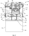
FIG. 7 is a cross-sectional view of a cleaning system, according to another embodiment of the disclosure, illustrating a wet-dry vacuum and cyclonic separator that is integrated with a power head of the wet-dry vacuum cleaner. -
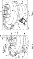
FIG. 8A is a partial cross-sectional view horizontally through the cyclonic separator ofFIG. 7 , illustrating an inlet port and airflow of the cyclonic separator. -
FIG. 8B is an upper view ofFIG. 8A , illustrating a separating plate and the airflow of the cyclonic separator. -
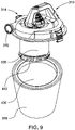
FIG. 9 is a perspective view a cleaning system, according to another embodiment of the disclosure, illustrating a wet-dry vacuum and cyclonic separator that is integrated with a power head of the wet-dry vacuum cleaner. -
FIG. 10 is a perspective cross-sectional view of the wet-dry vacuum cleaner ofFIG. 9 , taken through section line 10-10 ofFIG. 9 . -
FIG. 11 is a perspective cross-sectional view the wet-dry vacuum and cyclonic separator ofFIG. 9 , illustrating an alternate filter assembly useable with the wet-dry vacuum and cyclonic separator. - Before any embodiments of the disclosure are explained in detail, it is to be understood that the disclosure is not limited in its application to the details of construction and the arrangement of components set forth in the following description or illustrated in the following drawings. The disclosure is capable of other embodiments and of being practiced or of being carried out in various ways. Also, it is to be understood that the phraseology and terminology used herein is for the purpose of description and should not be regarded as limiting.
- Use of "including" and "comprising" and variations thereof as used herein is meant to encompass the items listed thereafter and equivalents thereof as well as additional items. Use of "consisting of' and variations thereof as used herein is meant to encompass only the items listed thereafter and equivalents thereof. Unless specified or limited otherwise, the terms "mounted," "connected," "supported," and "coupled" and variations thereof are used broadly and encompass both direct and indirect mountings, connections, supports, and couplings.
-
FIG. 1 illustrates a prior art example of acyclonic separator 1 that couples with a utility bucket 2 (e.g., cannister, bin, five gallon pale, etc.) and is disposed separate and upstream of a wet-dry vacuum cleaner 3. Thecyclonic separator 1 includes a dirtyair inlet port 4 and a cleanair outlet port 5 at the top center of thecyclonic separator 1. The dirtyair inlet port 4 is fluidly coupled to a firstflexible hose 6a with an opposite free orsuction end 7, and the cleanair outlet port 5 is fluidly coupled to a secondflexible hose 6b with an opposite end fluidly coupled to aninlet port 8 on the wet-dry vacuum cleaner 3. In operation, the wet-dry vacuum cleaner 3 is turned on, and a suction motor operates to draw in dirty air from thesuction end 7 of the firstflexible hose 6a. The dirty air passes through thecyclonic separator 1 where the air spins causing relatively heavier debris to separate from the airstream and collect in theutility bucket 2. The airflow then passes out of the cleanair outlet port 5 to the secondflexible hose 6b and into the wet-dry vacuum cleaner 3 through theinlet port 8. The cleanair outlet port 5 may further support anelbow connection 9 coupled between the cleanair outlet port 5 and the secondflexible hose 6b. -
FIGS. 2A and 2B illustrate a wet-dry vacuum cleaner 10, according to an embodiment of the present disclosure. The wet-dry vacuum cleaner 10 includes apower head 14, a bin 18 (e.g., a collecting bin, debris cannister, bucket, etc.), and acyclonic separator 22 integrated with the wet-dry vacuum cleaner 10 between thepower head 14 and thebin 18. In some embodiments, thebin 18 can be received by abase 20, such as an elevating base, a rolling base, and/or the like. Thepower head 14 incudes asuction motor 26 energized to rotate afan 30, such as an impeller, and generate a suction airflow through a portion of thepower head 14. Thepower head 14 further includes apre-motor filter 34 that hangs downward from thepower head 14 adjacent thesuction motor 26 andfan 30. Thepre-motor filter 34 is supported in apre-motor filter housing 35 that further supports thepower head 14 on thebin 18. The suction airflow, from thebin 18, travels through thepre-motor filter 34 before moving across thefan 30 and exhausting through anoutlet port 36 on thepower head 14. - The
power head 14 also includes apower source 38. In the illustrated embodiment, thepower source 38 includes a DC source, such as a removable or integrated battery. As shown inFIG. 2A , thepower source 38 may be received beneath acover 42 pivotally coupled to thepower head 14. In other embodiments, an AC power source, such as a wall outlet, may be utilized to power thepower head 14. In some embodiments, a combination of AC and DC power may be used to power thepower head 14,suction motor 26, or the like. - Referring to
FIGS. 2A-6 , thepower head 14 is supported on thepre-motor filter housing 35, which is attachable to anupper rim 50 of thecyclonic separator 22 via a plurality oflatches 54 to connect thepower head 14 to thecyclonic separator 22. Thecyclonic separator 22 is in turn attached to anupper rim 58 of thebin 18 by latches 62 (e.g., over-center-type latches), such that thecyclonic separator 22 is disposed between theupper rim 58 of thebin 18 and a lower edge 66 (FIG. 2B ) of thepre-motor filter housing 35. In other words, thepower head 14 is connected to thebin 18 through thecyclonic separator 22 and through thepre-motor filter housing 35. In instances where the wet-dry vacuum cleaner 10 is operated without thecyclonic separator 22, thelatches 62 may connect thepower head 14 directly to thebin 18, and thebin 18 may include an inlet similar to the dirtyair inlet port 70 on thecyclonic separator 22. In such instance, thepre-motor filter housing 35 is received directly in thebin 18 and thelatches 54 on thepre-motor filter housing 35 sit freely in an unlatched position. - With specific reference to
FIG. 2A , thecyclonic separator 22 includes a dirtyair inlet port 70 and a cleanair outlet port 74 at the top center of thecyclonic separator 22. The dirtyair inlet port 70 is fluidly coupled to aflexible hose 78 with an opposite free orsuction end 82, and the cleanair outlet port 74 is fluidly coupled to aninlet port 86 on thepower head 14 through thepre-motor filter housing 35. - The
cyclonic separator 22 can be an integrated component of the wet-dry vacuum cleaner 10 or could be a separately sold component (e.g., after market part or accessory) that can be added to a typical wet-dry vacuum cleaner to increase an effectiveness (e.g., suction force, operating strength, etc.) of dirt separation by removing thepower head 14 from thebin 18 and inserting thecyclonic separator 22 between the bin 18 and thepower head 14 in a stacked configuration, as illustrated inFIG. 2B . In some embodiments, thecyclonic separator 22 may be omitted such that the wet-dry vacuum cleaner 10 could be selectively operable like a typical wet-dry vacuum cleaner without thecyclonic separator 22 or operable with thecyclonic separator 22. - In operation, the wet-
dry vacuum cleaner 10 can be turned on (e.g., energized) to operate thesuction motor 26 and draw dirty air into thecyclonic separator 22 from the free or suction end 82 of theflexible hose 78. The dirty air passes through thecyclonic separator 22 where the air spins and causes relatively heavier debris to separate from an airstream and collect in thebin 18. The airflow then passes radially inwardly through a centrally-locatedcylindrical screen 90, up through the cleanair outlet port 74, through thepre-motor filter 34, and out of thepower head 14 through theoutlet port 36. In some embodiments, the airflow passes through the centrally-locatedcylindrical screen 90 and above a float assembly before passing through the cleanair outlet port 74 andpre-motor filter 34. In the illustrated embodiment, the airflow passes substantially vertically from thecyclonic separator 22, through the cleanair outlet port 74, through thepre-motor filter 34, and through thefan 30. In other words, the airflow path from thecyclonic separator 22 into thepower head 14 is principally vertical. -
FIG. 3 illustrates the wet-dry vacuum cleaner 10 with thecyclonic separator 22 connected between thepower head 14 and the 18. More specifically, thelatches 54 between thepre-motor filter housing 35 and thecyclonic separator 22 are positioned in a latched position in which thepower head 14 is stacked on thecyclonic separator 22 and connected to thecyclonic separator 22.FIG. 3 further illustrates thelatches 62 between thecyclonic separator 22 and thebin 18 in a latched position in which thecyclonic separator 22 is stacked on thebin 18 and connected to thebin 18 via thelatches 62. - As shown in
FIG. 3 , thelatches 54 between thepre-motor filter housing 35 and thecyclonic separator 22 may be metal clasp-type latches. In other embodiments, other types of connectors may be used to attach thecyclonic separator 22 to thepre-motor filter housing 35, such as a threaded twist connection, bayonet connection, a stacking interface, a detent mechanism, and/or the like. As also shown inFIG. 3 , thelatches 62 between thecyclonic separator 22 and thebin 18 are moveably mounted to thebin 18 and may be over-center-type latches or another type of connector. In some embodiments, thelatches 62 are moveably mounted to thecyclonic separator 22 and latched to thebin 18. When latched, alip 94 on thelatches 62 extends over acomplementary edge 98 on thecyclonic separator 22, and thelip 94 is set to a stop position in which thelatches 62 remains biased in the latched position. - When unlatched, as illustrated in
FIG. 4 , thelatches 62 between thecyclonic separator 22 and thebin 18 are opened such that thelip 94 does not extend over thecomplementary edge 98 and thelip 94 is not biased to the stop position. Rather, when unlatched, thelip 94 generally sits freely. In other embodiments, thelip 94 may be temporarily biased into the unlatched position once an unlocking or opening force is applied to thelatches 62. As further illustrated inFIG. 4 , thelatches 62 include ahinge assembly 99 that may accommodate biasing of thelatches 62 in the locked/latched position (FIG. 3 ). - When unlatched, as also illustrated in
FIGS. 5 and 6 , thelatches 62 between thecyclonic separator 22 and thebin 18 are opened such that thecyclonic separator 22 is removable from thebin 18.FIG. 5 further illustrates thepower head 14,pre-motor filter housing 35, andcyclonic separator 22 being lifted away from thebin 18, whileFIG. 6 further illustrates thepower head 14,pre-motor filter housing 35, andcyclonic separator 22 totally lifted away from thebin 18 to expose acollection chamber 100 within thebin 18. - As described above, the heavier debris (e.g., stones, wood scrap, metal pieces, sand, etc.) separated from the airstream within the
cyclonic separator 22 falls from the airstream and into thebin 18, and the remaining airstream proceeds upstream to thepre-motor filter 34. When thecyclonic separator 22 is attached to thebin 18, the larger or heavier debris is collected within thecollection chamber 100 in thebin 18. While in the totally lifted away position shown inFIG. 6 , the debris may be removed from thebin 18 to empty out thecollection chamber 100. -
FIGS. 7-8B illustrate a wet-dry vacuum cleaner 110, according to another embodiment of the present disclosure. The wet-dry vacuum cleaner 110 ofFIGS. 7-8B is similar to the wet-dry vacuum cleaner 10 described above with reference toFIGS. 2A-6 , and similar aspects of the wet-dry vacuum cleaner 110 are identified with similar reference numbers, plus "100." Some of the differences between the wet-dry vacuum cleaner 10 and the wet-dry vacuum cleaner 110 are described. - Referring to
FIG. 7 , the wet-dry vacuum cleaner 110 includes apower head 114, a bin 118 (e.g., a collecting bin, debris cannister, bucket, etc.), and acyclonic separator 122 integrated with the wet-dry vacuum cleaner 110 and within thepower head 114. As illustrated inFIG. 7 , thecyclonic separator 122 is connected directly to thepower head 114 and surrounds apre-motor filter housing 135 supporting apre-motor filter 134. Thepower head 114 andcyclonic separator 122 are further collectively attached to thebin 118. - The
power head 114 further incudes ahousing 123 having anouter wall 124 that streamlines a transition from thecyclonic separator 122 and through thepower head 114. As best shown inFIG. 7 , theouter wall 124 andhousing 123 further houses thecyclonic separator 122 within thepower head 114. Thepower head 114 further incudes asuction motor 126 energized to rotate afan 130, such as an impeller, and generate a working or suction airflow through a portion of thepower head 114. Thepre-motor filter 134 is supported in thepower head 114 and hangs downward adjacent thesuction motor 126 andfan 130. Thepre-motor filter 134 is supported in thepre-motor filter housing 135 that fluidly connects with thecyclonic separator 122 and extends to thesuction motor 126. The working airflow travels through thecyclonic separator 122, through a cleanair outlet port 174 in thecyclonic separator 122, and into thepre-motor filter 134 before moving across thefan 130 and exhausting through anoutlet port 136 on thepower head 114. In the illustrated embodiment, the cleanair outlet port 174 is centrally located on thecyclonic separator 122 and is surrounded by a centrally-locatedcylindrical screen assembly 190. -
FIG. 7 further illustrates afloat assembly 140 centrally lower than the cleanair outlet port 174 of thecyclonic separator 122. Thefloat assembly 140 includes afloat puck 141 that will close off the cleanair outlet port 174 when a liquid (e.g., fluid, water, and/or the like) level within thebin 118 reaches a predetermined height, such as a max height, full level, and/or the like. Stated another way, thefloat puck 141 sits in a dropped position (FIG. 7 ) until the liquid reaches a surface of thefloat puck 141 and raises thefloat puck 141 into a blocking position in which thefloat puck 141 closes off the cleanair outlet port 174. As the liquid level continues to rise, thefloat puck 141 will raise with the fluid level until the fluid level is high enough to bear thefloat puck 141 against the cleanair outlet port 174. Once thefloat puck 141 is high enough (e.g., in the blocking position), thefloat puck 141 will inhibit liquid from passing out of thebin 118 and into the cleanair outlet port 174 toward thesuction motor 126. Thefloat puck 141 may also close off the cleanair outlet port 174 to halt operation of thesuction motor 126. In such instances, thesuction motor 126 may communicate with a sensor, trigger, and/or the like and receive a command to deenergize (e.g., shut off, halt rotation of thefan 130, etc.). - The
power head 114 also includes apower source 138 similar to the power source(s) 38 of the wet-dry vacuum cleaner 10. Referring still toFIG. 7 , thepower head 114 is supported on thehousing 123, and thecyclonic separator 122 is integrally formed with thehousing 123 to connect and fluidly communicate thebin 118 with thesuction motor 126. In some embodiments, thepower head 114 is integrally connected to thehousing 123. In other embodiments, thepower head 114 is removably coupled to thehousing 123, including thecyclonic separator 122, and thehousing 123 is in turn removably coupled to anupper rim 158 of thebin 118 by latches 162 (e.g., over-center-type latches, snap latches, etc.), such that thecyclonic separator 122 is disposed between theupper rim 158 of thebin 118 and alower edge 166 of thepre-motor filter housing 135. In other words, thepower head 114 is connected to thebin 118 through thehousing 123, and thecyclonic separator 122 andpre-motor filter housing 135 are fully integrated into thepower head 114. - Referring now to
FIGS. 7 ,8A, and 8B , thecyclonic separator 122 includes a dirtyair inlet port 170 and the cleanair outlet port 174 at the top center of thecyclonic separator 122. The dirtyair inlet port 170 may be fluidly coupled to a flexible hose (e.g.,flexible hose 78 ofFIG. 2A ) with an opposite free or suction end, and the cleanair outlet port 174 is fluidly coupled to a suction motorhousing inlet port 186 on thepower head 114 through thepre-motor filter housing 135, including thefan 130 andpre-motor filter 134. - In the illustrated embodiment, the
cyclonic separator 122 may be referred to as an integrated component of the wet-dry vacuum cleaner 110 that increases an effectiveness (e.g., suction force, operating strength, etc.) of dirt separation accomplished by thepower head 114 by decreasing an amount of debris that travels to thepre-motor filter 134, thus allowing for more air to flow through thepre-motor filter 134 and to thesuction motor 126. In some embodiments, thepower head 114 is sealable to thebin 118 by a bayonet connection and/or a snap-fit connection 164, in which a portion of thecyclonic separator 122 is open to thebin 118. In other embodiments, thehousing 123 forms a half or clamshell portion of thecyclonic separator 122, and a portion of thehousing 123 is connectable with thecyclonic separator 122 and thebin 118. - In operation, the wet-
dry vacuum cleaner 110 can be turned on (e.g., energized) to operate thesuction motor 126 and draw adirty air 188 into thecyclonic separator 122 through the dirtyair inlet port 170. As best shown inFIGS. 8A and 8B ,dirty air 188 coming into thepower head 114 will enter tangentially into acyclonic chamber 199 of thecyclonic separator 122 and cause thedirty air 188 to spin cyclonically within thecyclonic chamber 199. Thecyclonic separator 122 further causes the relatively heavier debris (e.g., dirty liquid droplets, dirt, stones, wood scrap, metal pieces, sand, etc.) to be forced radially outwardly relative the cleanair outlet port 174, thereby separating the heavier debris from thedirty air 188 and resulting inclean air 189 moving through the cleanair outlet port 174. - It should be stated that the
clean air 189 refers to the working airflow that does not include the heavier debris described above. Theclean air 189 will still pass through the centrally-locatedcylindrical screen assembly 190 with working airflow laden with lighter debris (e.g., dust, particles, fine grains, etc.). However, it should be understood that the lighter debris will be separated from theclean air 189 by thepre-motor filter 134 such that the working airflow passing over/adjacent thesuction motor 126 does not damage thesuction motor 126. - With continued reference to
FIGS. 7 ,8A, and 8B , the separated heavier debris will fall into a collection chamber 200 (FIG. 7 ) of thebin 118 through aplate 210 positioned at least partially within thecyclonic chamber 199 and supported by thecyclonic separator 122. Theplate 210 includes acutout 214 positioned between adefining wall 218 of thecyclonic chamber 199 and a portion of theplate 210. The definingwall 218 may be an outer or even outermost wall of thecyclonic separator 122. The definingwall 218 may, in some embodiments, align with theouter wall 124 of thepower head 114, and may further define at least a portion of the cyclonical airflow path. - In the illustrated embodiment, the
cutout 214 includes anopening 222 extending along the definingwall 218 and alarger relief opening 226 that terminates theopening 222. As shown inFIG. 8B , theopening 222 is generally arcuate. In other embodiments, thecutout 214 includes an opening having a different shape. In general, the opening accommodates separation of the heavier debris and allows the heavier debris to fall from thedirty air 188 and into thecollection chamber 200. Thelarger relief opening 226 may be positioned anywhere along thecutout 214 but is illustrated as being disposed in a radial airflow path of thedirty air 188 and upstream of the remainder of thecutout 214 and/oropening 222. - As illustrated in
FIG. 8B , thecutout 214 extends around more than 50% (e.g., approximately 65%) of an entire radial surface of the definingwall 218. In some embodiments, thecutout 214 extends around more than 75% (e.g., approximately 85%) of the entire radial surface of the definingwall 218. In other embodiments, thecutout 214 extends around more than 95% (e.g., approximately 100%) of the entire radial surface of the definingwall 218. In yet another embodiment, thecutout 214 extends around less than 50% (e.g., approximately 30%) of the entire radial surface of the definingwall 218, while in even another embodiment, thecutout 214 extends around less than 25% (e.g., approximately 10%) of the entire radial surface of the definingwall 218. In such embodiments in which thecutout 214 extends around less than 25% of the entire radial surface of the definingwall 218, thecutout 214 may be made up of primarily thelarger relief opening 226. - After the heavier debris is separated from the
dirty air 188, the resultingclean air 189 will then move radially inwardly toward the cleanair outlet port 174 and floatassembly 140. Theclean air 189 will pass through the centrally-locatedcylindrical screen assembly 190 and travel up through the cleanair outlet port 174 of thecyclonic separator 122 and toward thepre-motor filter 134 of thepower head 114. From there, theclean air 189 will be substantially void of lighter debris and the "filtered" working air will pass through thefan 130 and be exhausted from thepower head 114 through theoutlet port 136. - In some embodiments, the
outlet port 136 includes one or more exhaust vents. The working airflow travels through thecyclonic separator 122, through the cleanair outlet port 174 in thecyclonic separator 122, and into thepre-motor filter 134 before moving across thefan 130 and exhausting through theoutlet port 136 on thepower head 114. As further illustrated inFIG. 8A , thebin 118 can be received by abase 120, such as an elevating base, a rolling base, and/or the like. -
FIGS. 9 and10 illustrate a wet-dry vacuum cleaner 310, according to another embodiment of the present disclosure. The wet-dry vacuum cleaner 310 ofFIGS. 9 and10 is similar to the wet-dry vacuum cleaner 110 described above with reference toFIGS. 7-8B , and similar aspects of the wet-dry vacuum cleaner 310 are identified with similar reference numbers, plus "200." It should be understood that the wet-dry vacuum cleaner 310 is also inherently similar to the wet-dry vacuum cleaner 10 described above with reference toFIGS. 2A-6 . Some of the differences between the wet-dry vacuum cleaner 110 and the wet-dry vacuum cleaner 310 are described. - Referring to
FIG. 9 , the wet-dry vacuum cleaner 310 includes apower head 314, a bin 318 (e.g., a collecting bin, debris cannister, bucket, etc.), and acyclonic separator 322 integrated with the wet-dry vacuum cleaner 310 and within thepower head 314. As illustrated inFIG. 10 , thecyclonic separator 322 is disposed directly within thepower head 314 and surrounds apre-motor filter housing 335 supporting apre-motor filter 334. Thepower head 314, including thecyclonic separator 322, can be selectively attached to thebin 318. - The
power head 314 further incudes ahousing 323 having anouter wall 324 that streamlines a transition from thecyclonic separator 322 and through thepower head 314. As best shown inFIG. 10 , theouter wall 324 andhousing 323 further houses thecyclonic separator 322 within thepower head 314. Thepower head 314 further incudes asuction motor 326 energized to rotate afan 330, such as an impeller, and generate a working or suction airflow through a portion of thepower head 314. Thepre-motor filter 334 is supported in thepower head 314 and hangs downward adjacent thesuction motor 326 andfan 330. Thepre-motor filter 334 is supported in thepre-motor filter housing 335, which is fluidly connected with thecyclonic separator 322 and extends to thesuction motor 326. - Generally, working airflow travels through the
cyclonic separator 322, through a cleanair outlet port 374 in thecyclonic separator 322, and into thepre-motor filter 334 before moving across thefan 330 and exhausting through anoutlet port 336 on thepower head 314. In some embodiments, theoutlet port 336 allows air to exhaust radially outwardly. In the illustrated embodiment, the cleanair outlet port 374 is centrally located on thecyclonic separator 322 and extends into thepre-motor filter housing 335. In some embodiments, the wet-dry vacuum cleaner 310 includes a float assembly that will close off the cleanair outlet port 374 when a liquid (e.g., fluid, water, and/or the like) level within thebin 318 reaches a predetermined height, such as a max height, full level, and/or the like. - The
power head 314 also includes apower source 338 similar to the power source(s) 38, 138 of the wet-dry vacuum cleaner - Referring still to
FIG. 10 , thecyclonic separator 322 includes a dirtyair inlet port 370 and the cleanair outlet port 374 at the top center of thecyclonic separator 322. The dirtyair inlet port 370 may be fluidly coupled to a flexible hose (e.g.,flexible hose 78 ofFIG. 2A ) with an opposite free or suction end, and the cleanair outlet port 374 is fluidly coupled to a suction motorhousing inlet port 386 in thepower head 314 through thepre-motor filter housing 335, including thefan 330 andpre-motor filter 334. In the illustrated embodiment, thepre-motor filter 334 to the suction motorhousing inlet port 386 are fluidly connected by aconduit 387. In some embodiments, the cleanair outlet port 374 at least partially surrounds theconduit 387. - In the illustrated embodiment, the
cyclonic separator 322 may be referred to as an integrated component of the wet-dry vacuum cleaner 310 that increases an effectiveness (e.g., suction force, operating strength, etc.) of dirt separation accomplished by thepower head 314 by decreasing an amount of debris that travels to thepre-motor filter 334, thus allowing for more air to flow through thepre-motor filter 334 and to thesuction motor 326. In operation, the wet-dry vacuum cleaner 310 can be turned on (e.g., energized) to operate thesuction motor 326 and draw adirty air 388 into thecyclonic separator 322 through the dirtyair inlet port 370. Thedirty air 388 coming into thepower head 314 will enter tangentially into acyclonic chamber 399 of thecyclonic separator 322 and cause thedirty air 388 to spin cyclonically within thecyclonic chamber 399. Thecyclonic separator 322 further causes the relatively heavier debris (e.g., dirty liquid droplets, dirt, stones, wood scrap, metal pieces, sand, etc.) to be forced radially outwardly relative the cleanair outlet port 374, thereby separating the heavier debris from thedirty air 388 and resulting inclean air 389 moving through the cleanair outlet port 374. - With continued reference to
FIG. 10 , the separated heavier debris will fall into a collection chamber 400 (FIG. 9 ) of thebin 318 through aplate 410 positioned at least partially within thecyclonic chamber 399 and supported by thecyclonic separator 322. In the illustrated embodiment, theplate 410 includes a conical portion (e.g., may have a conical shape). Theplate 410 includes acutout 414 positioned between adefining wall 418 of thecyclonic chamber 399 and a portion of theplate 410. The definingwall 418 may be an outer or even outermost wall of thecyclonic separator 322 and/or the housing 323 (e.g., theouter wall 324 of thepower head 314. - In the illustrated embodiment, the
cutout 414 includes anopening 422 that accommodates separation of the heavier debris and allows the heavier debris to fall from thedirty air 388 and into thecollection chamber 400. After the heavier debris is separated from thedirty air 388, the resultingclean air 389 will then move radially inwardly toward the cleanair outlet port 374. In some embodiments, the resultingclean air 389 passes radially inwardly through a centrally-locatedcylindrical screen 390 before entering the cleanair outlet port 374. - The
clean air 389 will then travel down through the cleanair outlet port 374 of thecyclonic separator 322 and into thepre-motor filter housing 335. Theconduit 387 is generally sealed off from thedirty air 388 and the resultingclean air 389 so that no air enters into the suction motorhousing inlet port 386 without passing into thepre-motor filter housing 335. Once in thepre-motor filter housing 335, theclean air 389 will circle around thepre-motor filter housing 335 and pass radially through the exterior surface of thepre-motor filter 334 having a cylindrical shape or body. From there, theclean air 389 will be substantially void of lighter debris and the "filtered" working air will be drawn up through theconduit 387 to the suction motorhousing inlet port 386. The working air will then pass through thefan 330 and be exhausted from thepower head 314 through theoutlet port 336. - The working airflow travels through the
cyclonic separator 322, down through the cleanair outlet port 374 in thecyclonic separator 322, and through thepre-motor filter 334 before being drawn upwardly across thefan 330 and exhausting through theoutlet port 336 on thepower head 314. - As illustrated in
FIG. 10 , thepre-motor filter 334 is cylindrical and hangs down from thepower head 314 within thepre-motor filter housing 335. Thepre-motor filter housing 335 may include aremovable cap 412 threadably connected to thepre-motor filter housing 335. Theremovable cap 412 may include a bump or pin 416 that supports a bottom end of thepre-motor filter 334. In some embodiments, thepre-motor filter 334 has a recess, such as an aperture or guiding hole, that receives thepin 416. Thepre-motor filter 334 may be supported by other portions of thepre-motor filter housing 335 and/or theremovable cap 412. As further illustrated inFIG. 10 , thepre-motor filter housing 335 blends into the cleanair outlet port 374 in thecyclonic separator 322. An upper portion of thepre-motor filter 334, adjacent the instant air coming from the cleanair outlet port 374, may be solid (e.g., non-perforated, air-blocking, etc.) so as to force air toward afilter media 420 supported by thepre-motor filter 334. In the illustrated embodiments, thefilter media 420 forms a substantially cylindrical body of thepre-motor filter 334, and air passed through vertical side walls of thefilter media 420. Thepre-motor filter 334 and filtermedia 420 are further located below theplate 410 and in thecollection chamber 400 of thebin 318. Thepre-motor filter housing 335 further fully encloses thepre-motor filter 334 and filtermedia 420 to prevent any debris or dirty air circulating within thebin 318 from contaminating thefilter media 420. -
FIG. 11 illustrates an alternatepre-motor filter 334a housed within apre-motor filter housing 335a. Thepre-motor filter housing 335a blends (e.g., receives air) into the cleanair outlet port 374 in thecyclonic separator 322, and an upper portion of the alternatepre-motor filter 334a, adjacent the instant air coming from the cleanair outlet port 374, may be solid (e.g., non-perforated, air-blocking, etc.) so as to force air toward afilter media 420a supported by the alternatepre-motor filter 334a. In the illustrated embodiment ofFIG. 11 , thefilter media 420a forms a substantially flat puck-shaped body of the alternatepre-motor filter 334a and is positioned on a lower side of the alternatepre-motor filter 334a. Rather than air entering into the alternatepre-motor filter 334a through vertical side walls of thefilter media 420a, air enters into the alternatepre-motor filter 334a through a substantially horizontal base wall of thefilter media 420a and exits through a corresponding horizontal top wall. Thefilter media 420a may be retained in the alternatepre-motor filter 334a by one or more support vanes. - The embodiment(s) described above and illustrated in the figures are presented by way of example only and are not intended as a limitation upon the concepts and principles of the present disclosure. As such, it will be appreciated that variations and modifications to the elements and their configuration and/or arrangement exist within the spirit and scope of one or more independent aspects as described. For example, the various aspects of either wet-
dry vacuum cleaner latches
Claims (20)
- A wet-dry vacuum cleaner comprising:a collecting bin;a cyclonic separator removably coupled to the bin, the cyclonic separator including a dirty air inlet and a clean air outlet,a housing removably coupled to the cyclonic separator, the housing supporting a filter therein, the filter positioned adjacent the clean air outlet of the cyclonic separator when the housing is coupled to the cyclonic separator;a power head integrally formed on the housing, the power head including an exhaust outlet; anda suction motor assembly operable to create a working airflow path from the dirty air inlet, through the cyclonic separator, through the clean air outlet, and to the exhaust outlet,wherein the cyclonic separator is configured to separate heavier debris from the working airflow and discharge the separated heavier debris into the collecting bin.
- The wet-dry vacuum cleaner of claim 1, wherein the working airflow path from the cyclonic separator through the housing is substantially vertical, and wherein the wet-dry vacuum cleaner is configured to be battery operated.
- The wet-dry vacuum cleaner of claim 1, wherein the housing is selectively stackable on an upper portion of the cyclonic separator or directly coupled to the collecting bin.
- The wet-dry vacuum cleaner of claim 3, wherein the housing includes a first latch moveable to a latched position in which a portion of the first latch couples the housing to the cyclonic separator, and wherein while in the latched position, the housing supports the power head on top of the cyclonic separator in a stacked configuration.
- The wet-dry vacuum cleaner of claim 4, wherein the first latch is moveable to an unlatched position, and wherein the housing is configured to alternately be received within the collecting bin while the cyclonic separator is separated from the housing and the first latch is in the unlatched position.
- The wet-dry vacuum cleaner of claim 4, wherein the collecting bin includes a second latch moveable to a first latched position in which a portion of the second latch couples the cyclonic separator to the collecting bin, and wherein the second latch is moveable to a second latched position in which a portion of the second latch, while the cyclonic separator is removed from the wet-dry vacuum cleaner, couples the power head to the collecting bin..
- The wet-dry vacuum cleaner of claim 1, wherein the cyclonic separator includes one or more after market parts that can be integrated into the wet-dry vacuum cleaner in a stacked configuration, and wherein the cyclonic separator is configured to operate with a typical wet-dry vacuum cleaner in a non-stacked configuration.
- A wet-dry vacuum cleaner comprising:a collecting bin; anda power head removably coupled to the collecting bin, the power head includinga housing configured to support the power head on the collecting bin,an exhaust outlet,a cyclonic separator positioned within the housing, the cyclonic separator including a dirty air inlet, a chamber, and a clean air outlet,a suction motor assembly operable to create a working airflow path from the dirty air inlet to the exhaust outlet, anda filter disposed within a filter housing hanging downwardly from the suction motor assembly, the filter positioned within the working airflow path adjacent the clean air outlet of the cyclonic separator.
- The wet-dry vacuum cleaner of claim 8, wherein the cyclonic separator is fluidly disposed between the power head and the collecting bin, and wherein the cyclonic separator is configured to separate heavier debris from working air in the working airflow path.
- The wet-dry vacuum cleaner of claim 8, wherein the filter housing receives air from the clean air outlet of the cyclonic separator, wherein working air in the working airflow path passes over the cyclonic separator before entering the filter housing, and wherein working air is drawn from the clean air outlet of the cyclonic separator downwardly into the filter housing.
- The wet-dry vacuum cleaner of claim 10, wherein the filter includes a conduit upstream from the clean air outlet of the cyclonic separator, the conduit accommodating the working airflow path from the filter housing to the exhaust outlet.
- The wet-dry vacuum cleaner of claim 11, wherein the conduit is at least partially surrounded by the clean air outlet of the cyclonic separator.
- The wet-dry vacuum cleaner of claim 11, wherein the conduit passes through the clean air outlet of the cyclonic separator, and wherein the conduit separates working air entering the filter housing through the clean air outlet of the cyclonic separator from working air exiting the filter housing toward the exhaust outlet.
- The wet-dry vacuum cleaner of claim 8, wherein the filter is disposed fluidly downstream of the cyclonic separator and physically below the cyclonic separator, wherein working air in the working airflow path is drawn into the filter and travels away from the cyclonic separator, and wherein working air is drawn into the suction motor assembly and bypasses the cyclonic separator via the conduit after exiting the filter.
- The wet-dry vacuum cleaner of claim 14, wherein the filter includes a cylindrical body at least partially formed by filter media, and wherein working air is drawn horizontally through the filter media and then vertically toward the exhaust outlet.
- The wet-dry vacuum cleaner of claim 14, wherein the filter includes a flat body at least partially formed by filter media, and wherein working air is drawn vertically through the filter media and then vertically toward the exhaust outlet.
- A wet-dry vacuum cleaner comprising:a collecting bin;a power head removably coupled to the collecting bin, the power head includinga housing configured to support the power head on the collecting bin,dirty air inlet,an exhaust outlet, anda suction motor assembly operable to draw working air from the dirty air inlet and expel air through exhaust outlet;a cyclonic separator integrated within the housing, the cyclonic separator includinga plate configured to separate heavier debris from the working air, the plate having an opening defined between the plate and the housing of the power head, the opening allowing heavier debris to fall into the collecting bin, anda clean air outlet positioned within the housing of the power head, the clean air outlet configured to receive working air unladen of heavier debris;a filter housing hanging downwardly from the power head, the filter housing receiving air from the clean air outlet of the cyclonic separator;a filter supported within the filter housing, the filter being disposed fluidly downstream of the cyclonic separator; anda conduit extending from the filter toward the exhaust outlet, the conduit positioned physically in the cyclonic separator but fluidly disposed downstream of the cyclonic separator, the conduit physically separating working air entering into the filter housing though the clean air outlet and working air exiting the filter housing through the conduit.
- The wet-dry vacuum cleaner of claim 17, wherein working air is drawn into the filter and travels away from the cyclonic separator, and wherein working air is drawn into the suction motor assembly and bypasses the cyclonic separator via the conduit after exiting the filter.
- The wet-dry vacuum cleaner of claim 18, wherein the filter includes a cylindrical body at least partially formed by filter media, and wherein working air is drawn horizontally through the filter media and then vertically toward the exhaust outlet.
- The wet-dry vacuum cleaner of claim 18, wherein the filter includes a flat body at least partially formed by filter media, and wherein working air is drawn vertically through the filter media and then vertically toward the exhaust outlet.
Applications Claiming Priority (1)
| Application Number | Priority Date | Filing Date | Title |
|---|---|---|---|
| US202163153793P | 2021-02-25 | 2021-02-25 |
Publications (2)
| Publication Number | Publication Date |
|---|---|
| EP4049570A2 true EP4049570A2 (en) | 2022-08-31 |
| EP4049570A3 EP4049570A3 (en) | 2023-07-19 |
Family
ID=80461215
Family Applications (1)
| Application Number | Title | Priority Date | Filing Date |
|---|---|---|---|
| EP22158598.7A Pending EP4049570A3 (en) | 2021-02-25 | 2022-02-24 | Integrated cyclonic separator in a wet-dry vacuum |
Country Status (4)
| Country | Link |
|---|---|
| US (2) | US11910989B2 (en) |
| EP (1) | EP4049570A3 (en) |
| CN (1) | CN218588914U (en) |
| CA (1) | CA3150216A1 (en) |
Families Citing this family (4)
| Publication number | Priority date | Publication date | Assignee | Title |
|---|---|---|---|---|
| US20140237768A1 (en) | 2013-02-28 | 2014-08-28 | G.B.D. Corp. | Surface cleaning apparatus |
| US11980334B2 (en) | 2017-09-15 | 2024-05-14 | Omachron Intellectual Property Inc. | Surface cleaning apparatus |
| US20240225391A1 (en) * | 2023-01-11 | 2024-07-11 | Oneida Air Systems, Inc. | Low Profile Bucket Lid and Dust Cyclone |
| WO2025185228A1 (en) | 2024-03-04 | 2025-09-12 | Sharkninja Operating Llc | Handheld surface cleaner |
Citations (3)
| Publication number | Priority date | Publication date | Assignee | Title |
|---|---|---|---|---|
| US20150182083A1 (en) * | 2012-09-18 | 2015-07-02 | Alfred Kärcher Gmbh & Co. Kg | Vacuum cleaner |
| EP2895045B1 (en) * | 2012-09-14 | 2016-09-14 | Alfred Kärcher GmbH & Co. KG | Vacuum cleaner |
| US20200205624A1 (en) * | 2018-12-28 | 2020-07-02 | Tti (Macao Commercial Offshore) Limited | Portable extractor |
Family Cites Families (62)
| Publication number | Priority date | Publication date | Assignee | Title |
|---|---|---|---|---|
| US2295984A (en) * | 1941-02-17 | 1942-09-15 | Burgess C Wilson | Vacuum cleaner |
| SE333628B (en) | 1967-09-18 | 1971-03-22 | J Ekenberg | |
| SE366642B (en) | 1972-09-22 | 1974-05-06 | Electrolux Ab | |
| SE372415B (en) * | 1972-09-22 | 1974-12-23 | Electrolux Ab | |
| US3820310A (en) | 1973-01-29 | 1974-06-28 | Singer Co | Vacuum cleaner inlet baffle |
| US3896520A (en) | 1973-10-23 | 1975-07-29 | Spray Brite | Wet and dry vacuum cleaner |
| US4547206A (en) * | 1983-06-22 | 1985-10-15 | Royal Appliance Mfg. Co. | Vacuum cleaner |
| US4654926A (en) * | 1985-04-08 | 1987-04-07 | Central Quality Industries, Inc. | Vacuum cleaner |
| DK119093A (en) | 1993-10-22 | 1995-04-23 | Joergen Sjoegreen | Universal Vacuum Cleaner |
| US5746795A (en) * | 1995-12-18 | 1998-05-05 | Witter; Robert | Replaceable, self-cleaning cartridge for a cyclonic air cleaning device |
| CA2260428A1 (en) | 1999-01-26 | 2000-07-26 | Rajinder Jit Singh Uppal | Wet/dry vacuum cleaner and filter therefor |
| US6251296B1 (en) | 1999-07-27 | 2001-06-26 | G.B.D. Corp. | Apparatus and method for separating particles from a cyclonic fluid flow |
| KR100510644B1 (en) | 2000-02-17 | 2005-08-31 | 엘지전자 주식회사 | cyclone dust collector |
| DE10046110B8 (en) | 2000-09-18 | 2006-07-06 | Siemens Ag | Medical diagnostic device with patient recognition |
| WO2005011460A1 (en) | 2003-08-04 | 2005-02-10 | Koninklijke Philips Electronics N.V. | Cyclonic separator for separating particles from an airflow and vacuum cleaner including such a separator |
| US7293324B2 (en) | 2003-09-19 | 2007-11-13 | Techtronic Industries Co., Ltd. | Vacuum cleaner with level control |
| EP1535560B1 (en) | 2003-10-28 | 2013-03-13 | LG Electronics, Inc. | Dust-collecting device and vacuum cleaner for both wet and dry cleaning using the same |
| US7048783B2 (en) | 2004-04-13 | 2006-05-23 | Oreck Holdings, Llc | Vacuum cleaner air/liquid separator |
| KR100667869B1 (en) | 2004-12-22 | 2007-01-15 | 삼성광주전자 주식회사 | Dust collector of vacuum cleaner |
| US20060130449A1 (en) | 2004-12-22 | 2006-06-22 | Samsung Gwangju Electronics Co., Ltd. | Vacuum cleaner dust collecting apparatus |
| JP2006175214A (en) | 2004-12-22 | 2006-07-06 | Samsung Kwangju Electronics Co Ltd | Vacuum cleaner dust collector |
| US7559965B2 (en) | 2005-01-25 | 2009-07-14 | Samsung Gwangju Electronics Co., Ltd. | Cyclonic separating apparatus for vacuum cleaner which is capable of separately collecting water from dust |
| KR100647196B1 (en) | 2005-06-22 | 2006-11-23 | 삼성광주전자 주식회사 | Cyclone Dust Collector for Vacuum Cleaner |
| US7937803B2 (en) * | 2005-07-26 | 2011-05-10 | Witter Robert M | Bag hold-down for dust collection system |
| AU2006220438B2 (en) | 2005-09-23 | 2011-02-03 | Bissell Inc. | Vacuum cleaner with two stage filtration |
| US7282074B1 (en) * | 2006-04-28 | 2007-10-16 | Witter Robert M | Auxiliary dust collection system |
| US8146201B2 (en) | 2006-12-12 | 2012-04-03 | G.B.D. Corp. | Surface cleaning apparatus |
| US8869344B2 (en) | 2006-12-12 | 2014-10-28 | G.B.D. Corp. | Surface cleaning apparatus with off-centre dirt bin inlet |
| WO2008070962A1 (en) | 2006-12-12 | 2008-06-19 | Gbd Corp. | Surface cleaning apparatus |
| CN101730495B (en) | 2007-05-15 | 2013-10-23 | 皇家器具有限公司 | Cyclonic utility vacuum |
| CN102885600A (en) | 2007-10-23 | 2013-01-23 | 莱克电气股份有限公司 | Wet-and-dry two-purpose dust collector with separating device |
| US8161597B2 (en) * | 2008-06-16 | 2012-04-24 | Oneida Air Systems, Inc. | Shop vacuum cleaner with cyclonic separator |
| US20100132317A1 (en) | 2008-11-21 | 2010-06-03 | Thien J Philip | Dust separator |
| NZ582896A (en) | 2009-02-05 | 2011-12-22 | John Charles Turner | A modular cleaning system adaptable to perform a number of cleaning tasks that can recycle water used |
| DE102009040489A1 (en) | 2009-09-08 | 2011-03-10 | Holger Lepold | suction device |
| WO2011050637A1 (en) | 2009-10-29 | 2011-05-05 | 莱克电气股份有限公司 | Dry and wet dual purpose vacuum cleaner |
| WO2011132323A1 (en) | 2010-04-22 | 2011-10-27 | 三立機器株式会社 | Vacuum cleaner for both dry and wet applications |
| US8337580B2 (en) * | 2010-09-03 | 2012-12-25 | Manska Wayne E | Debris separator |
| KR20120052692A (en) | 2010-11-16 | 2012-05-24 | 삼성전자주식회사 | Cyclone dust collecting apparatus and vacuum cleaner having the same |
| GB2489408B (en) | 2011-03-23 | 2015-08-05 | Techtronic Floor Care Tech Ltd | Suction cleaner |
| US9675220B2 (en) | 2011-06-10 | 2017-06-13 | Carl L. C. Kah, Jr. | Wet/dry, non-porous bag/bagless vacuum assembly with steam and variable speed settable vacuum motor control with no loss of suction |
| CN103767628B (en) | 2012-10-19 | 2017-02-08 | 莱克电气股份有限公司 | Dual-use wet and dry vacuum cleaner with separating device |
| CN202859029U (en) | 2012-10-19 | 2013-04-10 | 莱克电气股份有限公司 | Dry-wet dual-purpose dust collector with air inlet cover |
| CN203138362U (en) | 2013-03-01 | 2013-08-21 | 莱克电气股份有限公司 | Dry and wet dual-purpose dust collector with flow guide groove |
| WO2016170431A1 (en) | 2015-03-10 | 2016-10-27 | Kaivac, Inc. | Portable liquid-recycling liquid-reusing cleaning system for hard surface flooring |
| CN205054024U (en) | 2015-07-30 | 2016-03-02 | 博世电动工具(中国)有限公司 | Cyclone -type dust collector |
| CN204862986U (en) | 2015-07-30 | 2015-12-16 | 博世电动工具(中国)有限公司 | Cyclone type duster |
| US10857550B2 (en) | 2016-03-21 | 2020-12-08 | Thomas Huntley | Low profile dust separator |
| AU2017100402A4 (en) | 2016-04-10 | 2017-07-27 | Norton, Mathew Raymund MR | Dry and Wet Pre Separator Apparatus & Wet Vacuum Cyclone Chamber Invention |
| US10653281B2 (en) | 2017-08-25 | 2020-05-19 | Emerson Electric Co. | Pre-filter bag for vacuum cleaner and vacuum cleaner including same |
| CN107595204B (en) | 2017-10-31 | 2022-10-25 | 卓力电器集团有限公司 | Two-stage dust-air separation cyclone type dust cup capable of absorbing water and dust collector thereof |
| CN208740860U (en) | 2017-10-31 | 2019-04-16 | 卓力电器集团有限公司 | A kind of second level dust and gas separation cyclone dust cup and its dust catcher that can be absorbed water |
| CN208435487U (en) | 2018-02-26 | 2019-01-29 | 江苏美的清洁电器股份有限公司 | Separation device for wet and dry vacuum cleaners and wet and dry vacuum cleaners |
| EP3552531A1 (en) * | 2018-04-09 | 2019-10-16 | HILTI Aktiengesellschaft | Separating device for dust suction device |
| CN208988709U (en) | 2018-07-27 | 2019-06-18 | 珠海格力电器股份有限公司 | Dry-wet dual-purpose cyclone separation assembly and dust collector |
| CN108720726B (en) | 2018-07-27 | 2024-05-10 | 珠海格力电器股份有限公司 | Dry-wet dual-purpose cyclone separation assembly and dust collector |
| CN209220120U (en) | 2018-07-30 | 2019-08-09 | 珠海格力电器股份有限公司 | Gas-solid-liquid separation device and dust collector with same |
| CN108991989B (en) | 2018-07-30 | 2020-08-11 | 珠海格力电器股份有限公司 | Gas-solid-liquid separation device and dust collector with same |
| CN209186567U (en) | 2018-08-27 | 2019-08-02 | 珠海格力电器股份有限公司 | Float stop mechanism and dust catcher |
| CN109091066B (en) | 2018-08-27 | 2024-08-23 | 珠海格力电器股份有限公司 | Floating stop mechanism and vacuum cleaner |
| CN209269566U (en) | 2018-12-13 | 2019-08-20 | 苏州市格美纳电器有限公司 | A kind of dust collect plant and the dust catcher with it |
| CN210643878U (en) | 2019-05-08 | 2020-06-02 | 邦辰环保科技(苏州)有限公司 | A dry-wet dual-use separation device and a vacuum cleaner |
-
2022
- 2022-02-23 US US17/678,806 patent/US11910989B2/en active Active
- 2022-02-24 EP EP22158598.7A patent/EP4049570A3/en active Pending
- 2022-02-25 CN CN202220428102.3U patent/CN218588914U/en active Active
- 2022-02-25 CA CA3150216A patent/CA3150216A1/en active Pending
-
2024
- 2024-01-24 US US18/421,251 patent/US20240156317A1/en active Pending
Patent Citations (3)
| Publication number | Priority date | Publication date | Assignee | Title |
|---|---|---|---|---|
| EP2895045B1 (en) * | 2012-09-14 | 2016-09-14 | Alfred Kärcher GmbH & Co. KG | Vacuum cleaner |
| US20150182083A1 (en) * | 2012-09-18 | 2015-07-02 | Alfred Kärcher Gmbh & Co. Kg | Vacuum cleaner |
| US20200205624A1 (en) * | 2018-12-28 | 2020-07-02 | Tti (Macao Commercial Offshore) Limited | Portable extractor |
Also Published As
| Publication number | Publication date |
|---|---|
| EP4049570A3 (en) | 2023-07-19 |
| US20220265104A1 (en) | 2022-08-25 |
| CA3150216A1 (en) | 2022-08-25 |
| US20240156317A1 (en) | 2024-05-16 |
| CN218588914U (en) | 2023-03-10 |
| US11910989B2 (en) | 2024-02-27 |
Similar Documents
| Publication | Publication Date | Title |
|---|---|---|
| US11910989B2 (en) | Integrated cyclonic separator in a wet-dry vacuum | |
| CN101730495B (en) | Cyclonic utility vacuum | |
| US12035872B2 (en) | Handheld vacuum cleaner | |
| US11627852B2 (en) | Vacuum cleaner | |
| CN101420895B (en) | Single stage cyclonic vacuum cleaner | |
| AU674359B2 (en) | Wet/dry utility vacuum cleaner | |
| US6896719B2 (en) | Dirt collecting system for a floor care appliance | |
| US7544226B2 (en) | Grille for a cyclone vacuum | |
| GB2456192A (en) | Sloped upper wall of cyclone inflow channel | |
| CN101184422A (en) | Twin Cyclone Vacuum Cleaner | |
| GB2463089A (en) | Directing air into a grille | |
| KR20100135634A (en) | Dust collector of vacuum cleaner with dust removal function | |
| AU2017423525B2 (en) | Vacuum cleaner | |
| CN101940454A (en) | Built-in suspended cyclone separator | |
| WO2021126687A1 (en) | Vacuum cleaner | |
| EP2835088B1 (en) | Separation system for wet vacuum cleaners | |
| US10433691B2 (en) | Separator assembly for a suction cleaning apparatus | |
| CN223262846U (en) | High-efficient cyclone dust and gas separation dirt cup | |
| CN119055130A (en) | A high-efficiency cyclone dust and gas separation dust cup | |
| KR100578332B1 (en) | Separation plate for dust collecting casing of vacuum cleaner and dust collecting casing using same | |
| KR100546622B1 (en) | Dust collector of vacuum cleaner | |
| CN216535180U (en) | Dust separation module for cleaning machine and cleaning machine | |
| GB2428210A (en) | Dust collecting apparatus for a cyclonic vacuum cleaner | |
| KR101221299B1 (en) | Cyclone cleaner | |
| KR100546628B1 (en) | Dust collector of vacuum cleaner |
Legal Events
| Date | Code | Title | Description |
|---|---|---|---|
| PUAI | Public reference made under article 153(3) epc to a published international application that has entered the european phase |
Free format text: ORIGINAL CODE: 0009012 |
|
| STAA | Information on the status of an ep patent application or granted ep patent |
Free format text: STATUS: REQUEST FOR EXAMINATION WAS MADE |
|
| 17P | Request for examination filed |
Effective date: 20220224 |
|
| AK | Designated contracting states |
Kind code of ref document: A2 Designated state(s): AL AT BE BG CH CY CZ DE DK EE ES FI FR GB GR HR HU IE IS IT LI LT LU LV MC MK MT NL NO PL PT RO RS SE SI SK SM TR |
|
| PUAL | Search report despatched |
Free format text: ORIGINAL CODE: 0009013 |
|
| AK | Designated contracting states |
Kind code of ref document: A3 Designated state(s): AL AT BE BG CH CY CZ DE DK EE ES FI FR GB GR HR HU IE IS IT LI LT LU LV MC MK MT NL NO PL PT RO RS SE SI SK SM TR |
|
| RIC1 | Information provided on ipc code assigned before grant |
Ipc: A47L 5/22 20060101ALI20230613BHEP Ipc: A47L 9/16 20060101ALI20230613BHEP Ipc: A47L 5/36 20060101ALI20230613BHEP Ipc: A47L 7/00 20060101AFI20230613BHEP |
|
| STAA | Information on the status of an ep patent application or granted ep patent |
Free format text: STATUS: EXAMINATION IS IN PROGRESS |
|
| 17Q | First examination report despatched |
Effective date: 20250811 |