EP1535560B1 - Dust-collecting device and vacuum cleaner for both wet and dry cleaning using the same - Google Patents
Dust-collecting device and vacuum cleaner for both wet and dry cleaning using the same Download PDFInfo
- Publication number
- EP1535560B1 EP1535560B1 EP20040024856 EP04024856A EP1535560B1 EP 1535560 B1 EP1535560 B1 EP 1535560B1 EP 20040024856 EP20040024856 EP 20040024856 EP 04024856 A EP04024856 A EP 04024856A EP 1535560 B1 EP1535560 B1 EP 1535560B1
- Authority
- EP
- European Patent Office
- Prior art keywords
- dust
- collecting
- guide
- water
- filter
- Prior art date
- Legal status (The legal status is an assumption and is not a legal conclusion. Google has not performed a legal analysis and makes no representation as to the accuracy of the status listed.)
- Expired - Lifetime
Links
- 238000005108 dry cleaning Methods 0.000 title claims description 12
- 238000004891 communication Methods 0.000 claims description 63
- 230000002093 peripheral effect Effects 0.000 claims description 58
- XLYOFNOQVPJJNP-UHFFFAOYSA-N water Substances O XLYOFNOQVPJJNP-UHFFFAOYSA-N 0.000 claims description 58
- 239000000126 substance Substances 0.000 claims description 41
- 239000003599 detergent Substances 0.000 claims description 36
- 238000005192 partition Methods 0.000 claims description 35
- 239000011358 absorbing material Substances 0.000 claims description 2
- 238000007789 sealing Methods 0.000 description 8
- 239000000428 dust Substances 0.000 description 7
- 210000003739 neck Anatomy 0.000 description 6
- 238000009434 installation Methods 0.000 description 5
- 125000006850 spacer group Chemical group 0.000 description 5
- 238000004140 cleaning Methods 0.000 description 4
- 238000012546 transfer Methods 0.000 description 4
- 230000002745 absorbent Effects 0.000 description 1
- 239000002250 absorbent Substances 0.000 description 1
- 238000009825 accumulation Methods 0.000 description 1
- 230000006978 adaptation Effects 0.000 description 1
- 239000000853 adhesive Substances 0.000 description 1
- 230000001070 adhesive effect Effects 0.000 description 1
- 230000002411 adverse Effects 0.000 description 1
- 230000015572 biosynthetic process Effects 0.000 description 1
- 239000000356 contaminant Substances 0.000 description 1
- 230000000694 effects Effects 0.000 description 1
- 230000005489 elastic deformation Effects 0.000 description 1
- 238000003780 insertion Methods 0.000 description 1
- 230000037431 insertion Effects 0.000 description 1
- 230000002452 interceptive effect Effects 0.000 description 1
- 239000007788 liquid Substances 0.000 description 1
- 239000000463 material Substances 0.000 description 1
- 238000000034 method Methods 0.000 description 1
- 238000012986 modification Methods 0.000 description 1
- 230000004048 modification Effects 0.000 description 1
- 230000001681 protective effect Effects 0.000 description 1
- 230000002787 reinforcement Effects 0.000 description 1
- 238000005507 spraying Methods 0.000 description 1
Images


Classifications
-
- A—HUMAN NECESSITIES
- A47—FURNITURE; DOMESTIC ARTICLES OR APPLIANCES; COFFEE MILLS; SPICE MILLS; SUCTION CLEANERS IN GENERAL
- A47L—DOMESTIC WASHING OR CLEANING; SUCTION CLEANERS IN GENERAL
- A47L7/00—Suction cleaners adapted for additional purposes; Tables with suction openings for cleaning purposes; Containers for cleaning articles by suction; Suction cleaners adapted to cleaning of brushes; Suction cleaners adapted to taking-up liquids
- A47L7/0004—Suction cleaners adapted to take up liquids, e.g. wet or dry vacuum cleaners
- A47L7/0042—Gaskets; Sealing means
-
- A—HUMAN NECESSITIES
- A47—FURNITURE; DOMESTIC ARTICLES OR APPLIANCES; COFFEE MILLS; SPICE MILLS; SUCTION CLEANERS IN GENERAL
- A47L—DOMESTIC WASHING OR CLEANING; SUCTION CLEANERS IN GENERAL
- A47L7/00—Suction cleaners adapted for additional purposes; Tables with suction openings for cleaning purposes; Containers for cleaning articles by suction; Suction cleaners adapted to cleaning of brushes; Suction cleaners adapted to taking-up liquids
- A47L7/0004—Suction cleaners adapted to take up liquids, e.g. wet or dry vacuum cleaners
- A47L7/0009—Suction cleaners adapted to take up liquids, e.g. wet or dry vacuum cleaners with means mounted on the nozzle; nozzles specially adapted for the recovery of liquid
-
- A—HUMAN NECESSITIES
- A47—FURNITURE; DOMESTIC ARTICLES OR APPLIANCES; COFFEE MILLS; SPICE MILLS; SUCTION CLEANERS IN GENERAL
- A47L—DOMESTIC WASHING OR CLEANING; SUCTION CLEANERS IN GENERAL
- A47L7/00—Suction cleaners adapted for additional purposes; Tables with suction openings for cleaning purposes; Containers for cleaning articles by suction; Suction cleaners adapted to cleaning of brushes; Suction cleaners adapted to taking-up liquids
- A47L7/0004—Suction cleaners adapted to take up liquids, e.g. wet or dry vacuum cleaners
- A47L7/0023—Recovery tanks
- A47L7/0028—Security means, e.g. float valves or level switches for preventing overflow
Definitions
- the present invention relates to a vacuum cleaner capable of performing wet cleaning, and more particularly, to a vacuum cleaner for both wet and dry cleaning, wherein water and a detergent are sprayed and then sucked back together with foreign substances that in turn are separated by a dust-collecting device provided in the vacuum cleaner.
- a vacuum cleaner is one of household electric appliances, which can perform cleaning by generating a strong suction force in a main body or a nozzle of the vacuum cleaner, sucking contaminants existing on an area to be cleaned into the main body and collecting them therein.
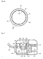
- Fig. 1 shows the configuration of a conventional vacuum cleaner for both wet and dry cleaning.
- a fan/motor assembly 2 for generating a suction force is provided within a main body 1 of the vacuum cleaner.
- a dust-collecting canister 3 is installed within the main body 1 to collect water and foreign substances except air among sucked matters.
- An upper portion of the dust-collecting canister 3 is shielded by a cover 4 that is formed with a first discharge port 5 for allowing only air passing through the dust-collecting canister 3 to be discharged therethrough.
- a floater guide 7 is formed at a position corresponding to the first discharge port 5 of the cover 4.
- a floater 8 for selectively opening or closing the first discharge port 5 is installed in the floater guide 7.
- the floater guide 7 is perforated to have a plurality of inlet holes 7a.
- One side of the main body 1 is provided with a second discharge port 9 through which air with the water and the detergent removed therefrom among the matters sucked through the nozzle assembly is discharged back to the outside.
- the second discharge port 9 is a portion through which air that has passed through the first discharge port and the fan/motor assembly 2 is discharged.
- the water and the foreign substances are rotated at high speed within the dust-collecting canister 3 by means of the strong cyclonic suction force.
- the strong cyclonic suction force there is a problem in that a part of the water is splashed on an inner wall surface of the dust-collecting canister 3 and then transferred directly to the floater guide 7.
- the water transferred to the floater guide 7 at high speed and with large impulse is introduced together with the air into the floater guide 7 through the inlet holes 7a of the floater guide 7. Further, the water has adverse effects on the fan/motor assembly 2 or other parts within the main body 1 while passing through the first discharge port 5 by the suction force from the fan/motor assembly 2.
- CA 2260428 A discloses a vacuum cleaner for both wet and dry operations which includes a debris canister, within which a cyclonic suction/exhaust flow that carries vacuumed debris may be established, a vacuum fan and a motor assembly.
- the vacuum cleaner also includes a conical filter surrounding a valve assembly positioned to limit the accumulation of liquid debris within the debris canister to a threshold level where a discharge port from the canister is blocked by means of the valve.
- DE 3405749 A discloses a vacuum cleaner for both wet and dry operations which is not based on the cyclone principle and which has a cylindrical pleated filter element surrounded by a protective tube provided with openings.
- An object of the present invention is to prevent water from being transferred to the exterior of a dust-collecting canister in a vacuum cleaner for both wet and dry cleaning.
- Another object of the present invention is to ensure securer collection of water and foreign substances in a vacuum cleaner for both wet and dry cleaning.
- a further object of the present invention is to ensure securer installation of parts provided in a water tank in a vacuum cleaner for both wet and dry cleaning.
- a dust-collecting device comprising a dust-collecting tank for collecting water and foreign substances in a cyclone manner, the dust-collecting tank having a suction port formed such that air flows along an inner peripheral surface of a dust-collecting space defined therein; a tank cover portion for selectively shielding the dust-collecting space, the tank cover portion having a first discharge port; a floater guide including an inner space communicating with the first discharge port, a floater for opening or closing the first discharge port, and a plurality of communication holes formed along an outer peripheral surface of the floater guide; a dust-collecting filter provided to surround the outer peripheral surface of the floater guide in order to filter out foreign substances from air flowing from the dust-collecting space to the interior of the floater guide; and a water-blocking wall for surrounding the first discharge port with a gap with respect to an outer peripheral surface of the dust-collecting filter.
- the dust-collecting space is divided into upper and lower space sections by partition plate.
- the partition plates are at least two, each of the partition plates is constructed such that an extension of the center of rotation thereof passes closely by the center of the dust-collecting space, and an upper surface of each of the partition plates is formed with ribs for supporting the dust-collecting filter.
- the ribs are formed to protrude by a predetermined height from both upper and lower surfaces of each of the partition plates.
- the dust-collecting filter is fitted around an outer peripheral surface of a filter guide mounted on the tank cover portion to shield the floater guide, and the filter guide is formed with a plurality of communication holes.
- intermediate communication holes are formed along an entire intermediate portion of the outer peripheral surface of the filter guide, and peripheral communication holes are formed at positions corresponding to the intermediate communication holes along an entire intermediate portion of the outer peripheral surface of the floater guide.
- lower communication holes are formed along a lower end of the outer peripheral surface of the filter guide, and four-directional communication holes are formed along a lower end of the outer peripheral surface of the floater guide to communicate with some of the lower communication holes.
- a plurality of upper communication holes are formed at upper portions of the outer peripheral surface of the filter guide above the intermediate communication holes.
- the water-blocking wall is formed as an arcuate wall having a predetermined length between the dust-collecting filter and the suction port.
- the water-blocking wall is constructed in the form of a cylinder to surround the outer peripheral surface of the dust-collecting filter.
- a protection portion made of a sound-absorbing material is provided on an outer surface of the water-blocking wall.
- the water-blocking wall is provided on the tank cover portion.
- the water-blocking wall is formed integrally with the floater guide and then mounted on the tank cover portion.
- the water-blocking wall is detachably mounted on the floater guide.
- a plurality of lifting guide ribs are formed vertically on an inner wall surface of the floater guide.
- the lifting guide ribs protrude radially inward by a predetermined width from the inner wall surface of the floater guide such that a distance between tips of the lifting guide ribs are constant.
- Fig. 2 is an exploded perspective view showing a vacuum cleaner according to a preferred embodiment of the present invention
- Fig. 3 is a sectional view schematically showing the inner structure of a vacuum cleaner according to the embodiment of the present invention
- Fig. 4 is an exploded perspective view showing the structure of a dust tank of a vacuum cleaner according to the embodiment of the present invention
- Fig. 5 is an exploded perspective view showing the structures of a dust-collecting filter and a filter guide of a vacuum cleaner according to the embodiment of the present invention.
- a predetermined inner space 11 is formed in a main body 10 of the vacuum cleaner.
- a variety of parts for constructing the vacuum cleaner are installed in the inner space 11 of the main body 10.
- the main body 10 defines an external appearance of the main body 10.
- a motor assembly 12 is provided in the main body 10.
- the motor assembly 12 is a portion that generates a suction force for use in operations of the vacuum cleaner.
- One side of the main body 10 where the motor assembly 12 is provided is formed with a second discharge port 13 through which air that has passed through the motor assembly 12 is discharged to the exterior of the main body 10.
- a detergent tank 14 is provided in the main body 10.
- a detergent diluted with water at a predetermined ratio is contained in the detergent tank 14.
- a pump 15' is provided to supply the detergent and water contained in the detergent tank 14, and a detergent supply port 15 is provided at an outer surface of the main body 10.
- a detergent hose 19 is connected to the detergent supply port 15 so that the detergent and water pressurized by the pump 15' can be delivered to a nozzle assembly.
- a hose connection portion 16 is formed at another side of the main body 10.
- the hose connection portion 16 serves to cause the exterior of the main body 10 to communicate with the inner space 11, and more specifically, connects a suction port 22 of a dust-collecting tank 20 to a suction hose 18 to be described later.
- the suction hose 18 serves to transfer a detergent, water and the like sucked through the nozzle assembly into the main body 10.
- the substantially cylindrical dust-collecting tank 20 is installed at one side of the inner space 11 of the main body 10.
- the dust-collecting tank 20 is a portion for separating water and foreign substances from water, air and foreign substances sucked by means of the suction force from the motor assembly 12 and collecting the water and foreign substances.
- the dust-collecting tank 20 defines a dust-collecting space 21 therein.
- the dust-collecting space 21 has an open top and may be constructed in various configurations according to the shape of the inner space 11 of the main body 10.
- the suction port 22 for causing the dust-collecting space 21 to communicate with the suction hose 18 is formed to penetrate through a portion of an upper end of the dust-collecting tank 20.
- a wall for defining the suction port 22 extends into the dust-collecting space 21, and a portion of the wall on the side of an outlet of the suction port (a portion facing the interior of the dust-collecting space 21) is open so that it can perform a circular motion within the dust-collecting space 21.
- a seating guide 23 is provided along a periphery of the upper end of the dust-collecting tank 20.
- the seating guide 23 may be intermittently formed along the periphery of the upper end of the dust-collecting tank 20.
- the seating guide 23 is formed to radially extend by a predetermined width at a position slightly below the upper end of the dust-collecting tank 20.
- Reference numeral 24 designates a handle for lifting the dust-collecting tank 20.
- First and second partition plates 26 and 27 are provided within the dust-collecting tank 20 to partition the dust-collecting space 21 into upper and lower space sections.
- Each of the first and second partition plates 26 and 27 is formed in the form of a semi-circular plate.
- the first and second partition plates 26 and 27 are formed with hinge shafts 26' and 27' at positions corresponding to both ends of a diameter of the semi-circle of each of the first and second partition plates 26 and 27.
- the hinge shafts 26' and 27' are supported by structures formed on an inner surface of the dust-collecting tank 20 so as to function as the centers of rotation.
- the first and second partition plates 26 and 27 divide the dust-collecting space 21 into the upper and lower space sections, so that water and foreign substances collected in the lower space section cannot be affected by the suction force generated from the motor assembly 12.
- a communicating portion 28 is formed at one side of the first partition plate 26.
- the communicating portion 28 prevents the first partition plate 26 from interfering with the suction port 22 and simultaneously serves to transfer the water and foreign substances into the lower space section of the dust-collecting space 21 divided by the partition plates 26 and 27.
- Supporting ribs 29 are provided on upper surfaces of the first and second partition plates 26 and 27. Although each of the supporting ribs 29 takes the shape of a cylindrical protrusion, it is not necessarily to be shaped as such.
- the supporting ribs 29 serve to support a dust-collecting filter 60 to be described later. Therefore, the supporting ribs 29 are provided at positions corresponding to the dust-collecting filter 60 in a region corresponding to the center of the dust-collecting space 21.
- the supporting ribs 29 may also be provided on lower surfaces of the partition plates 26 and 27. In this case, it is not necessary to consider orientations of the partition plates 26 and 27 upon installation thereof.
- each of the partition plates 26 and 27 inside the supporting ribs 29 is provided with a semi-circular rib 29'.
- the semi-circular ribs 29' support spacer ribs 69 of the filter guide 62 to be described later.
- the partition plates 26 and 27 are installed horizontally within the dust-collecting tank 20. To this end, a structure for supporting necessary portions of the partition plates 26 and 27 is provided.
- the partition plates 26 and 27 can be horizontally supported due to the shape of the dust-collecting tank 20 itself or may be supported by additional supporting ribs protruding from a bottom surface of the dust-collecting tank 20.
- a main body cover 30 is mounted on the top of the main body 10.
- the main body cover 30 is seated on the main body 10 to shield the inner space 11 from the outside.
- the main body cover 30 defines an external appearance of the vacuum cleaner in cooperation with the main body 10.
- Reference numeral 32 designates a handle.
- a lower surface of the main body cover 30 is provided with a tank cover portion 40.
- the tank cover portion 40 serves to shield the dust-collecting space 21 of the dust-collecting tank 20 from the outside. That is, the tank cover portion functions to define a partition between the inner space 11 and the dust-collecting space 21.
- the tank cover portion 40 is formed with a first discharge port 41 therethrough at a portion corresponding to the center of the dust-collecting tank 20.
- the first discharge port 41 is a portion through which air is discharged from the dust-collecting tank 20.
- a water-blocking wall 43 is provided to surround the first discharge port 41 of the tank cover portion 40.
- the water-blocking wall 43 prevents water introduced into the dust-collecting tank 20 from exiting through the first discharge port 41.
- the water-blocking wall 43 generally takes the shape of a cylinder and thus has a substantially circular cross section. It will be apparent that the water-blocking wall 43 is not necessarily cylindrical but may have a semi-circular shape in cross section. This is to effectively shield at least a portion facing the suction port 22.
- a connection flow passage 45 for causing the motor assembly 12 to communicate with the first discharge port 41 is provided in the main body cover 30.
- the connection flow passage 45 provided in the main body cover 30 causes the motor assembly 12 to communicate with the first discharge port 41 when the main body cover 30 is mounted on the main body 10.
- a floater guide 50 is installed on the tank cover portion 40. As well shown in Fig. 5 , the floater guide 50 generally takes the shape of a cylinder of which the diameter of an upper portion is relatively larger than that of a lower portion thereof. An inner space 51 of the floater guide 50 is formed to communicate with the first discharge port 41. A plurality of lifting guide ribs 51' are formed to extend vertically within the inner space 51 of the floater guide 50. The plurality of lifting guide ribs 51' are arranged at a predetermined interval.
- the lifting guide ribs 51' are constructed such that the diameter of a circle defined by tips of the lifting guide ribs is constant throughout the entire lengths thereof. This is achieved because the diameter of the upper portion of the inner space 51 is relatively larger than that of the lower portion thereof but the radially inward protruding widths of the lifting guide ribs 51' increase toward the upper portion of the inner space.
- the lifting guide ribs 51' allow a predetermined gap to be maintained between an outer peripheral surface of a floater 52 to be described below and an inner peripheral surface of the inner space 51.
- the floater 52 is provided within the floater guide 50.
- the floater 52 serves to selectively open and close the first discharge port 41. That is, if the dust-collecting space 21 is filled with water and foreign substances up to a predetermined level, the floater 52 clogs the first discharge port 41 by means of pressure generated by the motor assembly 12.
- Peripheral communication holes 53 are formed along the outer peripheral surface of the floater guide 50.
- the peripheral communication holes 53 are formed in a line along the outer peripheral surface of the floater guide 50 at an approximately intermediate position of the entire height of the floater guide.
- the peripheral communication holes 53 are separated from one another by the lifting guide ribs 51'.
- Four-directional communication holes 54 are formed at predetermined positions at a lower end of the outer peripheral surface of the floater guide 50.
- Four four-directional communication holes 54 are formed in total at an angular interval of about 90 degrees.
- the peripheral communication holes 53 and the four-directional communication holes 54 serve to cause the inner space 51 to communicate with the outside.
- a mounting flange 55 is formed along the upper end of the floater guide 50.
- the mounting flange 55 protrudes radially outward to have a predetermined width.
- the mounting flange 55 is used to mount the floater guide 50 on the tank cover portion 40.
- the mounting flange 55 may be formed integrally with the tank cover portion 40.
- the floater guide 50 should be properly designed in shape.
- the water-blocking wall 43 may be formed integrally with the floater guide 50. That is, the water-blocking wall 43 may be formed integrally with and along a tip of the mounting flange 55 of the floater guide 50.
- a sealing member 56 is provided along an inner periphery on a lower surface of the mounting flange 55.
- the sealing member 56 ensures sealing by coming into close contact with a relevant portion of a filter guide 62 to be described later. Meanwhile, it is also preferred that a sealing member (not shown) be provided at a periphery of an entrance of the inner space 51 corresponding to an upper surface of the mounting flange 55.
- Wing-mounting members 57 are formed to protrude from the lower surface of the mounting flange 55.
- the wing-mounting members 57 are used to mount the filter guide 62 to the mounting flange 55.
- a reinforcement rib 57' is formed to protrude from a lower surface of each of the wing-mounting members 57.
- a tip guide 58 is provided at one end of each of the wing-mounting members 57.
- the tip guide 58 is formed approximately perpendicularly to a direction of the formation of the wing-mounting member 57.
- the tip guide 58 is connected through a connection neck 58' to the wing-mounting member 57.
- the connection neck 58' is constructed to be elastically deformed to a certain extent due to connection of only a portion of the neck to the wing-mounting member 57.
- a guide catching protrusion 59 is formed at an upper end of the tip guide 58, i.e. a portion thereof extending from the connection neck 58'.
- the guide catching protrusion 59 is formed to be upwardly inclined in a direction toward the connection neck 58' and in a direction opposite thereto, such that it is formed to protrude in the form of a triangle when viewed from a side.
- the guide catching protrusion 59 prevents a mounting wing 68, which has been mounted to the wing-mounting member 57, from being arbitrarily demounted therefrom.
- the dust-collecting filter 60 is provided to surround the floater guide 50.
- the dust-collecting filter 60 primarily serves to filter out fine dust.
- the dust-collecting filter 60 is formed to take the shape of a cylinder and has annular frames 61 at upper and lower ends.
- a dust-collecting portion 61' that is pleated and takes the shape of a cylinder is provided between the frames 61.
- the dust-collecting filter 60 is fixedly mounted to the filter guide 62.
- the dust-collecting filter 60 is installed to be fitted around an outer peripheral surface of the filter guide 62.
- the filter guide 62 generally takes the shape of a cylinder, and an inner space 63 thereof is open only upwardly, i.e. in a direction toward the first discharge port 41 in the same manner as the floater guide 50.
- Intermediate communication holes 64 are formed along the outer peripheral surface of the filter guide 62. As shown in Fig. 6b , the intermediate communication holes 64 are formed at positions conforming to the peripheral communication holes 53 of the floater guide 50. Therefore, the inner space 51 of the floater guide 50 can be viewed through the intermediate communication holes 64 and the peripheral communication holes 53 from the exterior of the filter guide 62.
- Lower communication holes 65 are formed at a lower end of the filter guide 62 below the intermediate communication holes 64.
- Three lower communication holes 65 constitute one set, and two sets of lower communication holes are provided at an angular interval of 180 degrees, i.e. at opposite sides of the outer peripheral surface of the filter guide 62. As shown in Fig. 6c , one of the lower communication holes in each set communicates with the four-directional communication hole 54.
- Upper communication holes 66 are formed just above the intermediate communication holes 64. Likewise, three upper communication holes 66 are also formed at an angular interval of 180 degrees. However, as shown in Fig. 6a , the upper communication holes 66 do not communicate directly with the inner space 51 of the floater guide 50. The positions where the upper and communication holes 66 and 65 are formed respectively at the upper and lower ends of the outer peripheral surface of the filter guide 62 partially overlap with each other.
- the gap is widened toward the lower end of the floater guide 50. Therefore, even though the lower or upper communication holes 65 or 66 do not communicate directly with the interior of the floater guide 50, they can communicate with the interior of the floater guide 50 through the gap.
- a filter stopper 67 is provided along the upper end of the filter guide 62.
- the filter stopper 67 serves to guide the insertion of the dust-collecting filter 60 in place. That is, the frame 61 provided at the upper end of the dust-collecting filter 60 is caught by the filter stopper 67 and thus cannot be further inserted.
- the mounting wings 68 are provided at the upper end of the filter guide 62 to be mounted to the wing-mounting members 57 of the mounting flange 55. Each of the mounting wings 68 is formed to protrude with a predetermined width and length from the upper end of the filter guide 62. Although the mounting wings 68 are formed at an angular interval of 120 degrees in this embodiment, they are not necessarily formed in such a manner.
- the spacer ribs 69 are formed to protrude from a lower surface of the filter guide 62.
- the spacer ribs 69 are supported by the semi-circular rib 29'.
- the spacer ribs 69 protrude by a predetermined length corresponding to a gap between the lower surface of the filter guide 62 and the partition plates 26 and 27.
- a motor assembly 112 is provided in a main body 110 of a vacuum cleaner.
- the motor assembly 112 is a portion that generates a suction force for use in operations of the vacuum cleaner.
- One side of the main body 110 where the motor assembly 112 is provided is formed with a second discharge port 113 through which air that has passed through the motor assembly 112 is discharged to the exterior of the main body 110.
- a detergent tank is provided in the main body 110 and contains a diluted detergent. The detergent contained in the detergent tank is delivered to the outside by a pump.
- a hose connection portion 116 is formed at another side of the main body 110.
- the hose connection portion 116 serves to cause the exterior of the main body 110 to communicate with a dust-collecting space 121 of a dust-collecting tank 120 to be described later.
- a suction hose 118 is connected to the hose connection portion 116.
- the suction hose 118 serves to transfer a detergent, water and the like sucked through a nozzle assembly into the dust-collecting tank 120.
- the substantially cylindrical dust-collecting tank 120 is installed at one side of the interior of the main body 110.
- the dust-collecting tank 120 is a portion for separating water and foreign substances from water, air and foreign substances sucked by means of the suction force from the motor assembly 112 and collecting the water and foreign substances.
- the dust-collecting tank 120 defines the dust-collecting space 121 therein.
- the dust-collecting space 121 has an open top.
- a suction port 122 for causing the dust-collecting space 121 to communicate with the suction hose 118 is formed to penetrate through a portion of an upper end of the dust-collecting tank 120.
- a wall for defining the suction port 122 extends into the dust-collecting space 121, and a portion of the wall on the side of an outlet of the suction port (a portion facing the interior of the dust-collecting space 121) is open so that it can perform a circular motion within the dust-collecting space 121.
- Other structures of the dust-collecting tank 120 may be similar to those of the previous embodiment.
- an additional main body cover may be provided on the main body 110.
- the main body cover serves to selectively shield the interior of the main body 110. Therefore, the main body cover may be provided in various forms at any positions so far as the main body cover can selectively shield the interior of the main body 110.
- the dust-collecting space 121 of the dust-collecting tank 120 has an open top.
- the open top of the dust-collecting tank 120 is shielded by a tank cover portion 140.
- the tank cover portion 140 can be formed integrally with the main body cover in the same manner as the previous embodiment or separately therefrom.
- the tank cover portion 140 is formed with a first discharge port 141 therethrough at a portion corresponding to the center of the dust-collecting tank 120.
- the first discharge port 141 is a portion through which air is discharged from the dust-collecting tank 120.
- a water-blocking wall 143 is provided to surround the first discharge port 141 of the tank cover portion 140.
- the water-blocking wall 143 prevents water introduced into the dust-collecting tank 120 from exiting through the first discharge port 141.
- the water-blocking wall 143 generally takes the shape of a cylinder and thus has a substantially circular cross section. It will be apparent that the water-blocking wall 143 is not necessarily cylindrical but may have a semi-circular shape in cross section. This is to effectively shield at least a portion facing the suction port 122.
- a floater guide 150 is installed on the tank cover portion 140.
- the floater guide 150 generally takes the shape of a cylinder of which the diameter of an upper portion is relatively larger than that of a lower portion thereof.
- An inner space 151 of the floater guide 150 is formed to communicate with the first discharge port 141.
- a floater 152 is provided within the inner space 151 of the floater guide 150. The floater 152 serves to selectively open and close the first discharge port 141. That is, if the dust-collecting space 121 is filled with water and foreign substances up to a predetermined level, the floater 152 clogs the first discharge port 141 by means of pressure generated by the motor assembly 112.
- Peripheral communication holes 153 are formed along an outer peripheral surface of the floater guide 150.
- the peripheral communication holes 53 may be formed at various positions throughout the outer peripheral surface of the floater guide 150.
- the floater guide 150 may be formed integrally with the tank cover portion 140, or may be formed separately from and then installed on the tank cover portion.
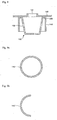
- Fig. 8 shows a structure in which that the floater guide 150 and the water-blocking wall 143 are formed separately from and then installed on the tank cover portion 140.
- the floater guide 150 may be bonded to the tank cover portion 140 using an adhesive or fastened thereto using screws or the like. It will be apparent that the floater guide may be mounted on the tank cover portion 140 in the same manner as the previous embodiment.
- Fig. 8 shows that a flange 155 is formed along a periphery of an upper end of the floater guide 150 and the water-blocking wall 143 is formed to extend downward from the upper end of the flange 155.
- Fig. 9 The shape of a cross section of the water-blocking wall 143 is shown in Fig. 9 . That is, Fig. 9a shows a water-blocking wall 143 with a circular cross section. At this time, the water-blocking wall 143 is placed to surround the floater guide 150. Fig. 9b shows a water-blocking wall 143' with a semi-circular cross section. The water-blocking wall 143' is placed between the suction port 122 and the floater guide 150.
- a motor assembly 212 is provided in a main body 210 of a vacuum cleaner.
- the motor assembly 212 is a portion that generates a suction force for use in operations of the vacuum cleaner.
- One side of the main body 210 where the motor assembly 212 is provided is formed with a second discharge port 213 through which air that has passed through the motor assembly 212 is discharged to the exterior of the main body 210.
- a detergent tank (not shown) is provided in the main body 210.
- a detergent diluted with water at a predetermined ratio is contained in the detergent tank.
- a pump 215' is provided to supply the detergent and water contained in the detergent tank to the outside, and a detergent supply port 215 is provided at an outer surface of the main body 210.
- a detergent hose (not shown) is connected to the detergent supply port 215 so that the detergent and water pressurized by the pump 215' can be delivered to a nozzle assembly.
- a hose connection portion 216 is formed at another side of the main body 210.
- the hose connection portion 216 connects a suction port 222 of a dust-collecting tank 220 to a suction hose 218 to be described later.
- the suction hose 218 serves to transfer a detergent, air and the like sucked through the nozzle assembly into the main body 210.
- the substantially cylindrical dust-collecting tank 220 is installed at one side of the interior of the main body 210.
- the dust-collecting tank 220 is a portion for separating water and foreign substances from water, air and foreign substances sucked by means of the suction force from the motor assembly 212 and collecting the water and foreign substances.
- the dust-collecting tank 220 defines a dust-collecting space 221 therein.
- the dust-collecting space 221 has an open top and may be constructed in various configurations according to the shape of the interior of the main body 210.
- a suction port 222 for causing the dust-collecting space 221 to communicate with the suction hose 218 is formed to penetrate through a portion of an upper end of the dust-collecting tank 220.
- a wall for defining the suction port 222 extends into the dust-collecting space 221, and a portion of the wall on the side of an outlet of the suction port (a portion facing the interior of the dust-collecting space 221) is open so that it can perform a circular motion within the dust-collecting space 221.
- a main body cover for selectively opening and closing the interior of the main body 210 be provided on one side of the main body 210.
- the main body cover may be installed at any positions on the main body 210, it is preferably installed at the top of the main body 210.
- the dust-collecting space 221 of the dust-collecting tank 220 is opened or closed by a tank cover portion 240.
- the tank cover portion 240 serves to shield the dust-collecting space 221 of the dust-collecting tank 220 from the outside, and may be provided on the main body cover or separately therefrom.
- the tank cover portion 240 is formed with a first discharge port 241 therethrough at a portion corresponding to the center of the dust-collecting tank 220.
- the first discharge port 241 is a portion through which air is discharged from the dust-collecting tank 220.
- a water-blocking wall 243 is provided to surround the first discharge port 241 of the tank cover portion 240.
- the water-blocking wall 243 prevents water introduced into the dust-collecting tank 220 from exiting through the first discharge port 241.
- the water-blocking wall 243 generally takes the shape of a cylinder and thus has a substantially circular cross section. It will be apparent that the water-blocking wall 243 is not necessarily cylindrical but may have a semi-circular shape in cross section. This is to effectively shield at least a portion facing the suction port 222.
- a protection portion 244 is provided to surround an outer peripheral surface of the water-blocking wall 243.
- the protection portion 244 absorbs impact generated when foreign substances collide against the water-blocking wall 243. Therefore, it is possible to eliminate noises generated upon collision of the foreign substances against the water-blocking wall 243. To this end, it is preferred that the protection portion 244 be made of a shock-absorbing and absorbent material.
- connection flow passage 245 causes the motor assembly 212 to communicate with the first discharge port 241.
- the connection flow passage 245 is preferably provided in the main body cover. It will be apparent that the connection flow passage 245 may be formed separately from the main body cover or integrally with the tank cover portion 240.
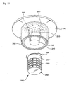
- a floater guide 250 is installed on the tank cover portion 240. As well shown in Fig. 11 , the floater guide 250 generally takes the shape of a cylinder of which the diameter of an upper portion is relatively larger than that of a lower portion thereof. An inner space 251 of the floater guide 250 is formed to communicate with the first discharge port 241.
- a floater 252 is provided within the interior of the floater guide 250.
- the floater 252 serves to selectively open and close the first discharge port 241. That is, if the dust-collecting space 221 is filled with water and foreign substances up to a predetermined level, the floater 252 clogs the first discharge port 241 by means of pressure generated by the motor assembly 212.
- Peripheral communication holes 253 are formed along an outer peripheral surface of the floater guide 250.
- the plurality of peripheral communication holes 253 are formed to be elongated vertically along the outer peripheral surface of the floater guide 250.
- a mounting flange 255 is formed along an upper end of the floater guide 250.
- the mounting flange 255 protrudes radially outward to have a predetermined width.
- the mounting flange 255 is used to mount the floater guide 250 on the tank cover portion 240.
- Wing-mounting members 257 are formed in the mounting flange 55.
- the plurality of wing-mounting members 257 are formed at a predetermined interval.
- the mounting flange 255 may be formed integrally with the tank cover portion 240.
- the floater guide 250 should be properly designed in shape.
- the water-blocking wall 243 may be formed integrally with the floater guide 250. That is, the water-blocking wall 243 may be formed integrally with and along a tip of the mounting flange 255 of the floater guide 250.
- a dust-collecting filter 260 is provided to surround the floater guide 250.
- the dust-collecting filter 260 primarily serves to filter out fine dust.
- the dust-collecting filter 260 is constructed as follows.
- the dust-collecting filter 260 is provided with a filter guide 262 for use in mounting the dust-collecting filter to the floater guide 250.
- a dust-collecting portion 261' is provided at an outer peripheral surface of the filter guide 262 to filter out fine dust.
- the filter guide 262 generally takes the shape of a cylinder, and an inner space thereof is open only upwardly, i.e. in a direction toward the first discharge port 241 in the same manner as the floater guide 250.
- a plurality of communication holes 264 are formed along the outer peripheral surface of the filter guide 262.
- the communication holes 264 are formed over various regions on the outer peripheral surface of the filter guide 262.
- Mounting wings 268 are provided at an upper end of the filter guide 262 to be mounted to the wing-mounting members 257 of the mounting flange 255.
- Each of the mounting wings 268 is formed to protrude with a predetermined width and length from the upper end of the filter guide 262.
- the dust-collecting tank 20 can be detachably mounted within the main body 10 in a state where the dust-collecting tank is separated from the main body cover 30.
- the floater guide 50 is mounted on the tank cover portion 40 provided in the main body cover 30.
- the inner space 51 of the floater guide 50 is caused to communicate with the connection flow passage 45 through the first discharge port 41.
- the floater guide 50 is fastened using screws.
- the filter guide 62 is mounted on the mounting flange 55 of the floater guide 50, particularly, by inserting the mounting wings 68 of the filter guide 62 into the wing-mounting members 57. This is performed by rotating the filter guide 62 with respect to the floater guide 50 in a state where upper surfaces of the mounting wings 68 are in close contact with the lower surface of the mounting flange 55. In this state, the mounting wings 68 move along the mounting flange 55, ride over the guide catching protrusions 59 and are then inserted into the wing-mounting members 57.
- the tip guides 58 including the guide catching protrusions 59 are pushed out and then restored due to elastic deformation of the connection necks 58' so that the mounting wings 68 can be caught by the wing-mounting members 57. It will be apparent that the plurality of mounting wings 68 are simultaneously caught by the wing-mounting members 57. Since one end of each of the mounting wings 68 is caught by the relevant guide catching protrusion 59, it cannot be arbitrarily demounted from the relevant wing-mounting member.
- the peripheral communication holes 53 are caused to match the intermediate communication holes 64.
- Some of the four-directional communication holes 54 communicate with the lower communication holes 65.
- Each of opposite ones of the four-directional communication holes 54 spaced apart at an angular interval of 180 degrees communicates with one of the relevant set of three lower communication holes 65.
- the upper communication holes 66 communicate not directly but indirectly through the peripheral communication holes 53 or the four-directional communication holes 54 with the inner space 51 of the floater guide 50.
- sealing is achieved therebetween by means of the sealing member. Sealing between the floater guide 50 and the filter guide 61 is also achieved by means of the sealing member 56, thereby preventing a suction force or water from leaking out.
- the dust-collecting filter 60 is inserted into the filter guide 62.
- the outer peripheral surface of the filter guide 62 is surrounded by the dust-collecting portion 61'. Therefore, air containing foreign substances passes through the dust-collecting portion 61' by means of the suction force transmitted through the communication holes 64, 65 and 66 formed in the filter guide 62.
- the floater guide 50, the filter guide 62 and the dust-collecting filter 60 are mounted on the tank cover portion 40 of the main body cover 30.
- the structures are constructed to be placed within the water-blocking wall 43. Therefore, as the main body cover 30 is mounted on the main body 10, the tank cover portion 40 shields the dust-collecting tank 20, and the dust-collecting filter 60 and the like are placed in the inner space 21 of the dust-collecting tank 20.
- the frame 61 provided at the lower end of the dust-collecting filter 60 is supported by or placed with a certain gap with respect to the supporting ribs 29 formed at the partition plates 26 and 27.
- the spacer ribs 69 of the filter guide 62 are placed on the semi-circular ribs 29' of the partition plates 26 and 27.
- the motor assembly 12 When an operating signal is provided to the vacuum cleaner, the motor assembly 12 is driven and generates a suction force. The suction force generated by the motor assembly 12 is transmitted to the nozzle assembly provided at a leading end of the suction hose 18 through the connection flow passage 45 and the dust-collecting tank 20.
- the detergent contained in the detergent tank 14 is delivered through a detergent supply port 15 and a detergent hose 19 to the nozzle assembly from which the detergent is sprayed to an area to be cleaned.
- the nozzle assembly sucks foreign substances and the detergent-mixed water together with air.
- the air is transferred to the suction port 22 through the suction hose 18, and performs circular motion along an inner peripheral surface of the dust-collecting space 21 of the dust-collecting tank 20 while exiting through the suction port 22.
- the water and large foreign substances remain in the dust-collecting space 21, whereas the air and fine foreign substances pass through the dust-collecting filter 60.
- the fine foreign substances entrained by the air are filtered out while passing through the dust-collecting portion 61' of the dust-collecting filter 60.
- the air that has passed through the dust-collecting portion 61' is transferred to the inner space 51 of the floater guide 50 through the communication holes 64, 65 and 66 of the filter guide 61 and the communication holes 53 and 54 of the floater guide 50.
- the air passes through the inner space 51, the first discharge port 41 and the connection flow passage 45 to the second discharge port 13 through which the air is discharged to the exterior of the main body 10.
- the water, foreign substances and air sucked by means of the suction force from the motor assembly 112 rotate along an inner wall of the dust-collecting tank 120.
- the water and foreign substances among them fall to a lower portion of the dust-collecting space 121, while the air flows into the floater guide 150.
- the air transferred to the interior of the floater guide 150 is sucked to the motor assembly 112 through the first discharge port 141.
- the air that has passed through the motor assembly 112 is discharged to the exterior of the vacuum cleaner through the second discharge port 113.
- the water-blocking wall 143 serves to prevent water or foreign substances from being transferred directly to the interior of the floater guide 150. Particularly, the water-blocking wall 143 prevents water from being transferred to the interior of the floater guide 150 between the suction port 122 and the floater guide 150.
- the filter 260 is provided in this embodiment, fine dust can be filtered out in the same manner as the embodiment shown in Fig. 2 . Further, since the connection flow passage 245 is provided within the main body 210 in this embodiment, more secure communication between the dust-collecting tank 220 and the motor assembly 212 can be achieved.
- the dust-collecting tank may take various shapes rather than a cylindrical shape.
- the partition plates will be formed to conform to the shape of the dust-collecting tank.
- the water-blocking wall may also take various shapes.
- the water-blocking wall may take any shapes capable of preventing at least water introduced through the suction port of the dust-collecting tank from being splashed to the dust-collecting filter.
- the dust-collecting filter, the filter guide and the like that have been formed separately from the dust-collecting tank and provided to the tank cover portion are supported by the partition plates within the dust-collecting tank in the present invention, they are prevented from being broken or changed in their installation states. Thus, there is an advantage in that product reliability of the vacuum cleaner is improved.
- the filter guide and the floater guide are constructed properly even with the presence of the dust-collecting filter in the present invention, there is an advantage in that water and foreign substances can be more effectively separated from air.
Landscapes
- Filters For Electric Vacuum Cleaners (AREA)
Description
- The present invention relates to a vacuum cleaner capable of performing wet cleaning, and more particularly, to a vacuum cleaner for both wet and dry cleaning, wherein water and a detergent are sprayed and then sucked back together with foreign substances that in turn are separated by a dust-collecting device provided in the vacuum cleaner.
- A vacuum cleaner is one of household electric appliances, which can perform cleaning by generating a strong suction force in a main body or a nozzle of the vacuum cleaner, sucking contaminants existing on an area to be cleaned into the main body and collecting them therein. Recently, there has been developed a vacuum cleaner that can perform wet cleaning with a wet duster mounted thereon, or perform wet cleaning by exchanging a simple accessory tool such as a nozzle assembly and repeatedly spraying water and a detergent from the vacuum cleaner itself and sucking the water and detergent, even while performing the basic function of collecting dry dust and the like.
-
Fig. 1 shows the configuration of a conventional vacuum cleaner for both wet and dry cleaning. Referring to this figure, a fan/motor assembly 2 for generating a suction force is provided within a main body 1 of the vacuum cleaner. A dust-collectingcanister 3 is installed within the main body 1 to collect water and foreign substances except air among sucked matters. An upper portion of the dust-collectingcanister 3 is shielded by acover 4 that is formed with afirst discharge port 5 for allowing only air passing through the dust-collectingcanister 3 to be discharged therethrough. - External water, foreign substances and air are sucked through a nozzle assembly (not shown) connected through a
suction hose 6 to the main body 1 and then introduced into the dust-colleting tank 3. The water and foreign substances are separated from the air in a cyclone manner within the dust-collectingcanister 3. Within the dust-collectingcanister 3, afloater guide 7 is formed at a position corresponding to thefirst discharge port 5 of thecover 4. Afloater 8 for selectively opening or closing thefirst discharge port 5 is installed in thefloater guide 7. Thefloater guide 7 is perforated to have a plurality ofinlet holes 7a. - One side of the main body 1 is provided with a
second discharge port 9 through which air with the water and the detergent removed therefrom among the matters sucked through the nozzle assembly is discharged back to the outside. Thesecond discharge port 9 is a portion through which air that has passed through the first discharge port and the fan/motor assembly 2 is discharged. - However, there are the following problems in the prior art described above.
- In the conventional vacuum cleaner, the water and the foreign substances are rotated at high speed within the dust-collecting
canister 3 by means of the strong cyclonic suction force. During such rotation of the water and the foreign substances, there is a problem in that a part of the water is splashed on an inner wall surface of the dust-collectingcanister 3 and then transferred directly to thefloater guide 7. - The water transferred to the
floater guide 7 at high speed and with large impulse is introduced together with the air into thefloater guide 7 through theinlet holes 7a of thefloater guide 7. Further, the water has adverse effects on the fan/motor assembly 2 or other parts within the main body 1 while passing through thefirst discharge port 5 by the suction force from the fan/motor assembly 2. -
CA 2260428 A discloses a vacuum cleaner for both wet and dry operations which includes a debris canister, within which a cyclonic suction/exhaust flow that carries vacuumed debris may be established, a vacuum fan and a motor assembly. The vacuum cleaner also includes a conical filter surrounding a valve assembly positioned to limit the accumulation of liquid debris within the debris canister to a threshold level where a discharge port from the canister is blocked by means of the valve. -
DE 3405749 A discloses a vacuum cleaner for both wet and dry operations which is not based on the cyclone principle and which has a cylindrical pleated filter element surrounded by a protective tube provided with openings. - Accordingly, the present invention is conceived to solve the aforementioned problems in the prior art. An object of the present invention is to prevent water from being transferred to the exterior of a dust-collecting canister in a vacuum cleaner for both wet and dry cleaning.
- Another object of the present invention is to ensure securer collection of water and foreign substances in a vacuum cleaner for both wet and dry cleaning.
- A further object of the present invention is to ensure securer installation of parts provided in a water tank in a vacuum cleaner for both wet and dry cleaning.
- According to an aspect of the present invention for achieving the objects, there is provided a dust-collecting device, comprising a dust-collecting tank for collecting water and foreign substances in a cyclone manner, the dust-collecting tank having a suction port formed such that air flows along an inner peripheral surface of a dust-collecting space defined therein; a tank cover portion for selectively shielding the dust-collecting space, the tank cover portion having a first discharge port; a floater guide including an inner space communicating with the first discharge port, a floater for opening or closing the first discharge port, and a plurality of communication holes formed along an outer peripheral surface of the floater guide; a dust-collecting filter provided to surround the outer peripheral surface of the floater guide in order to filter out foreign substances from air flowing from the dust-collecting space to the interior of the floater guide; and a water-blocking wall for surrounding the first discharge port with a gap with respect to an outer peripheral surface of the dust-collecting filter.
- Preferably, the dust-collecting space is divided into upper and lower space sections by partition plate.
- The partition plates are at least two, each of the partition plates is constructed such that an extension of the center of rotation thereof passes closely by the center of the dust-collecting space, and an upper surface of each of the partition plates is formed with ribs for supporting the dust-collecting filter.
- The ribs are formed to protrude by a predetermined height from both upper and lower surfaces of each of the partition plates.
- Further, the dust-collecting filter is fitted around an outer peripheral surface of a filter guide mounted on the tank cover portion to shield the floater guide, and the filter guide is formed with a plurality of communication holes.
- Preferably, intermediate communication holes are formed along an entire intermediate portion of the outer peripheral surface of the filter guide, and peripheral communication holes are formed at positions corresponding to the intermediate communication holes along an entire intermediate portion of the outer peripheral surface of the floater guide.
- More preferably, lower communication holes are formed along a lower end of the outer peripheral surface of the filter guide, and four-directional communication holes are formed along a lower end of the outer peripheral surface of the floater guide to communicate with some of the lower communication holes.
- A plurality of upper communication holes are formed at upper portions of the outer peripheral surface of the filter guide above the intermediate communication holes.
- Furthermore, the water-blocking wall is formed as an arcuate wall having a predetermined length between the dust-collecting filter and the suction port.
- Preferably, the water-blocking wall is constructed in the form of a cylinder to surround the outer peripheral surface of the dust-collecting filter.
- Further, a protection portion made of a sound-absorbing material is provided on an outer surface of the water-blocking wall.
- Furthermore, the water-blocking wall is provided on the tank cover portion.
- Preferably, the water-blocking wall is formed integrally with the floater guide and then mounted on the tank cover portion.
- More preferably, the water-blocking wall is detachably mounted on the floater guide.
- A plurality of lifting guide ribs are formed vertically on an inner wall surface of the floater guide.
- The lifting guide ribs protrude radially inward by a predetermined width from the inner wall surface of the floater guide such that a distance between tips of the lifting guide ribs are constant.
- With the present invention constructed as above, there are advantages in that water is prevented from being transferred to parts within the main body in the vacuum cleaner for both wet and dry cleaning, and the structure of the dust-collecting filter and the like provided in the dust-collecting tank can be maintained more securely.
- The above and other objects and features of the present invention will become apparent from the following description of preferred embodiments given in conjunction with the accompanying drawings, in which:
-
Fig. 1 is a sectional view showing the structure of a conventional vacuum cleaner; -
Fig. 2 is an exploded perspective view showing a vacuum cleaner in which a dust-collecting device according to an embodiment of the present invention is employed; -
Fig. 3 is a sectional view schematically showing the inner structure of vacuum cleaner according to the embodiment of the present invention; -
Fig. 4 is an exploded perspective view showing the structure of a dust tank of vacuum cleaner according to the embodiment of the present invention; -
Fig. 5 is an exploded perspective view showing the structures of a floater guide, a dust-collecting filter and a filter guide of vacuum cleaner according to the embodiment of the present invention; -
Fig. 6 is a sectional view showing the structures of a floater guide, a dust-collecting filter and a filter guide of vacuum cleaner according to the other embodiment of the present invention; -
Fig. 7 is a sectional view schematically showing the inner structure of vacuum cleaner according to the other embodiment of the present invention; -
Fig. 8 is a sectional view showing the structures of a tank cover portion of vacuum cleaner according to the other embodiment of the present invention; -
Fig. 9a is a sectional view showing the structure of a water-blocking wall of vacuum cleaner according to the other embodiment of the present invention; -
Fig. 9b is a sectional view showing the structure of a water-blocking wall of vacuum cleaner according to the other embodiment of the present invention -
Fig. 10 is an sectional view showing the structure of vacuum cleaner according to the another embodiment of the present invention; -
Fig. 11 is an exploded perspective view showing the structures of a tank cover portion and a dust-collecting of vacuum cleaner according to the another embodiment of the present invention; -
Fig. 2 is an exploded perspective view showing a vacuum cleaner according to a preferred embodiment of the present invention,Fig. 3 is a sectional view schematically showing the inner structure of a vacuum cleaner according to the embodiment of the present invention;Fig. 4 is an exploded perspective view showing the structure of a dust tank of a vacuum cleaner according to the embodiment of the present invention; andFig. 5 is an exploded perspective view showing the structures of a dust-collecting filter and a filter guide of a vacuum cleaner according to the embodiment of the present invention. - Referring to these figures, a predetermined
inner space 11 is formed in amain body 10 of the vacuum cleaner. A variety of parts for constructing the vacuum cleaner are installed in theinner space 11 of themain body 10. Themain body 10 defines an external appearance of themain body 10. Amotor assembly 12 is provided in themain body 10. Themotor assembly 12 is a portion that generates a suction force for use in operations of the vacuum cleaner. One side of themain body 10 where themotor assembly 12 is provided is formed with asecond discharge port 13 through which air that has passed through themotor assembly 12 is discharged to the exterior of themain body 10. - A
detergent tank 14 is provided in themain body 10. A detergent diluted with water at a predetermined ratio is contained in thedetergent tank 14. A pump 15' is provided to supply the detergent and water contained in thedetergent tank 14, and adetergent supply port 15 is provided at an outer surface of themain body 10. Adetergent hose 19 is connected to thedetergent supply port 15 so that the detergent and water pressurized by the pump 15' can be delivered to a nozzle assembly. - A
hose connection portion 16 is formed at another side of themain body 10. Thehose connection portion 16 serves to cause the exterior of themain body 10 to communicate with theinner space 11, and more specifically, connects asuction port 22 of a dust-collectingtank 20 to asuction hose 18 to be described later. Thesuction hose 18 serves to transfer a detergent, water and the like sucked through the nozzle assembly into themain body 10. - The substantially cylindrical dust-collecting
tank 20 is installed at one side of theinner space 11 of themain body 10. The dust-collectingtank 20 is a portion for separating water and foreign substances from water, air and foreign substances sucked by means of the suction force from themotor assembly 12 and collecting the water and foreign substances. The dust-collectingtank 20 defines a dust-collectingspace 21 therein. The dust-collectingspace 21 has an open top and may be constructed in various configurations according to the shape of theinner space 11 of themain body 10. - The structure of the dust-collecting
tank 20 will be described with reference toFig. 4 . Thesuction port 22 for causing the dust-collectingspace 21 to communicate with thesuction hose 18 is formed to penetrate through a portion of an upper end of the dust-collectingtank 20. A wall for defining thesuction port 22 extends into the dust-collectingspace 21, and a portion of the wall on the side of an outlet of the suction port (a portion facing the interior of the dust-collecting space 21) is open so that it can perform a circular motion within the dust-collectingspace 21. - A
seating guide 23 is provided along a periphery of the upper end of the dust-collectingtank 20. Theseating guide 23 may be intermittently formed along the periphery of the upper end of the dust-collectingtank 20. Theseating guide 23 is formed to radially extend by a predetermined width at a position slightly below the upper end of the dust-collectingtank 20.Reference numeral 24 designates a handle for lifting the dust-collectingtank 20. - First and
second partition plates tank 20 to partition the dust-collectingspace 21 into upper and lower space sections. Each of the first andsecond partition plates second partition plates second partition plates tank 20 so as to function as the centers of rotation. The first andsecond partition plates space 21 into the upper and lower space sections, so that water and foreign substances collected in the lower space section cannot be affected by the suction force generated from themotor assembly 12. - A communicating
portion 28 is formed at one side of thefirst partition plate 26. When thefirst partition plate 26 is opened or closed, the communicatingportion 28 prevents thefirst partition plate 26 from interfering with thesuction port 22 and simultaneously serves to transfer the water and foreign substances into the lower space section of the dust-collectingspace 21 divided by thepartition plates - Supporting
ribs 29 are provided on upper surfaces of the first andsecond partition plates ribs 29 takes the shape of a cylindrical protrusion, it is not necessarily to be shaped as such. The supportingribs 29 serve to support a dust-collectingfilter 60 to be described later. Therefore, the supportingribs 29 are provided at positions corresponding to the dust-collectingfilter 60 in a region corresponding to the center of the dust-collectingspace 21. The supportingribs 29 may also be provided on lower surfaces of thepartition plates partition plates - A portion of each of the
partition plates ribs 29 is provided with a semi-circular rib 29'. The semi-circular ribs 29'support spacer ribs 69 of thefilter guide 62 to be described later. - The
partition plates tank 20. To this end, a structure for supporting necessary portions of thepartition plates partition plates tank 20 itself or may be supported by additional supporting ribs protruding from a bottom surface of the dust-collectingtank 20. - Returning again to
Fig. 2 , amain body cover 30 is mounted on the top of themain body 10. Themain body cover 30 is seated on themain body 10 to shield theinner space 11 from the outside. Themain body cover 30 defines an external appearance of the vacuum cleaner in cooperation with themain body 10.Reference numeral 32 designates a handle. - As well shown in
Fig. 3 , a lower surface of themain body cover 30 is provided with atank cover portion 40. Thetank cover portion 40 serves to shield the dust-collectingspace 21 of the dust-collectingtank 20 from the outside. That is, the tank cover portion functions to define a partition between theinner space 11 and the dust-collectingspace 21. - The
tank cover portion 40 is formed with afirst discharge port 41 therethrough at a portion corresponding to the center of the dust-collectingtank 20. Thefirst discharge port 41 is a portion through which air is discharged from the dust-collectingtank 20. - A water-blocking
wall 43 is provided to surround thefirst discharge port 41 of thetank cover portion 40. The water-blockingwall 43 prevents water introduced into the dust-collectingtank 20 from exiting through thefirst discharge port 41. The water-blockingwall 43 generally takes the shape of a cylinder and thus has a substantially circular cross section. It will be apparent that the water-blockingwall 43 is not necessarily cylindrical but may have a semi-circular shape in cross section. This is to effectively shield at least a portion facing thesuction port 22. - A
connection flow passage 45 for causing themotor assembly 12 to communicate with thefirst discharge port 41 is provided in themain body cover 30. Theconnection flow passage 45 provided in themain body cover 30 causes themotor assembly 12 to communicate with thefirst discharge port 41 when themain body cover 30 is mounted on themain body 10. - A
floater guide 50 is installed on thetank cover portion 40. As well shown inFig. 5 , thefloater guide 50 generally takes the shape of a cylinder of which the diameter of an upper portion is relatively larger than that of a lower portion thereof. Aninner space 51 of thefloater guide 50 is formed to communicate with thefirst discharge port 41. A plurality of lifting guide ribs 51' are formed to extend vertically within theinner space 51 of thefloater guide 50. The plurality of lifting guide ribs 51' are arranged at a predetermined interval. - The lifting guide ribs 51' are constructed such that the diameter of a circle defined by tips of the lifting guide ribs is constant throughout the entire lengths thereof. This is achieved because the diameter of the upper portion of the
inner space 51 is relatively larger than that of the lower portion thereof but the radially inward protruding widths of the lifting guide ribs 51' increase toward the upper portion of the inner space. The lifting guide ribs 51' allow a predetermined gap to be maintained between an outer peripheral surface of afloater 52 to be described below and an inner peripheral surface of theinner space 51. - The
floater 52 is provided within thefloater guide 50. Thefloater 52 serves to selectively open and close thefirst discharge port 41. That is, if the dust-collectingspace 21 is filled with water and foreign substances up to a predetermined level, thefloater 52 clogs thefirst discharge port 41 by means of pressure generated by themotor assembly 12. - Peripheral communication holes 53 are formed along the outer peripheral surface of the
floater guide 50. The peripheral communication holes 53 are formed in a line along the outer peripheral surface of thefloater guide 50 at an approximately intermediate position of the entire height of the floater guide. The peripheral communication holes 53 are separated from one another by the lifting guide ribs 51'. Four-directional communication holes 54 are formed at predetermined positions at a lower end of the outer peripheral surface of thefloater guide 50. Four four-directional communication holes 54 are formed in total at an angular interval of about 90 degrees. The peripheral communication holes 53 and the four-directional communication holes 54 serve to cause theinner space 51 to communicate with the outside. - A mounting
flange 55 is formed along the upper end of thefloater guide 50. The mountingflange 55 protrudes radially outward to have a predetermined width. The mountingflange 55 is used to mount thefloater guide 50 on thetank cover portion 40. - It will be apparent that the mounting
flange 55 may be formed integrally with thetank cover portion 40. In this case, thefloater guide 50 should be properly designed in shape. Further, the water-blockingwall 43 may be formed integrally with thefloater guide 50. That is, the water-blockingwall 43 may be formed integrally with and along a tip of the mountingflange 55 of thefloater guide 50. - A sealing
member 56 is provided along an inner periphery on a lower surface of the mountingflange 55. The sealingmember 56 ensures sealing by coming into close contact with a relevant portion of afilter guide 62 to be described later. Meanwhile, it is also preferred that a sealing member (not shown) be provided at a periphery of an entrance of theinner space 51 corresponding to an upper surface of the mountingflange 55. - Wing-mounting
members 57 are formed to protrude from the lower surface of the mountingflange 55. The wing-mountingmembers 57 are used to mount thefilter guide 62 to the mountingflange 55. A reinforcement rib 57' is formed to protrude from a lower surface of each of the wing-mountingmembers 57. - A
tip guide 58 is provided at one end of each of the wing-mountingmembers 57. Thetip guide 58 is formed approximately perpendicularly to a direction of the formation of the wing-mountingmember 57. Thetip guide 58 is connected through a connection neck 58' to the wing-mountingmember 57. The connection neck 58' is constructed to be elastically deformed to a certain extent due to connection of only a portion of the neck to the wing-mountingmember 57. - A
guide catching protrusion 59 is formed at an upper end of thetip guide 58, i.e. a portion thereof extending from the connection neck 58'. Theguide catching protrusion 59 is formed to be upwardly inclined in a direction toward the connection neck 58' and in a direction opposite thereto, such that it is formed to protrude in the form of a triangle when viewed from a side. Theguide catching protrusion 59 prevents a mountingwing 68, which has been mounted to the wing-mountingmember 57, from being arbitrarily demounted therefrom. - The dust-collecting
filter 60 is provided to surround thefloater guide 50. The dust-collectingfilter 60 primarily serves to filter out fine dust. The dust-collectingfilter 60 is formed to take the shape of a cylinder and hasannular frames 61 at upper and lower ends. A dust-collectingportion 61' that is pleated and takes the shape of a cylinder is provided between theframes 61. - The dust-collecting
filter 60 is fixedly mounted to thefilter guide 62. The dust-collectingfilter 60 is installed to be fitted around an outer peripheral surface of thefilter guide 62. The filter guide 62 generally takes the shape of a cylinder, and aninner space 63 thereof is open only upwardly, i.e. in a direction toward thefirst discharge port 41 in the same manner as thefloater guide 50. - Intermediate communication holes 64 are formed along the outer peripheral surface of the
filter guide 62. As shown inFig. 6b , the intermediate communication holes 64 are formed at positions conforming to the peripheral communication holes 53 of thefloater guide 50. Therefore, theinner space 51 of thefloater guide 50 can be viewed through the intermediate communication holes 64 and the peripheral communication holes 53 from the exterior of thefilter guide 62. - Lower communication holes 65 are formed at a lower end of the
filter guide 62 below the intermediate communication holes 64. Three lower communication holes 65 constitute one set, and two sets of lower communication holes are provided at an angular interval of 180 degrees, i.e. at opposite sides of the outer peripheral surface of thefilter guide 62. As shown inFig. 6c , one of the lower communication holes in each set communicates with the four-directional communication hole 54. - Upper communication holes 66 are formed just above the intermediate communication holes 64. Likewise, three upper communication holes 66 are also formed at an angular interval of 180 degrees. However, as shown in
Fig. 6a , the upper communication holes 66 do not communicate directly with theinner space 51 of thefloater guide 50. The positions where the upper and communication holes 66 and 65 are formed respectively at the upper and lower ends of the outer peripheral surface of thefilter guide 62 partially overlap with each other. - There is the predetermined gap between the outer peripheral surface of the
floater guide 50 and the inner peripheral surface of thefilter guide 62. Particularly, the gap is widened toward the lower end of thefloater guide 50. Therefore, even though the lower or upper communication holes 65 or 66 do not communicate directly with the interior of thefloater guide 50, they can communicate with the interior of thefloater guide 50 through the gap. - A
filter stopper 67 is provided along the upper end of thefilter guide 62. Thefilter stopper 67 serves to guide the insertion of the dust-collectingfilter 60 in place. That is, theframe 61 provided at the upper end of the dust-collectingfilter 60 is caught by thefilter stopper 67 and thus cannot be further inserted. - The mounting
wings 68 are provided at the upper end of thefilter guide 62 to be mounted to the wing-mountingmembers 57 of the mountingflange 55. Each of the mountingwings 68 is formed to protrude with a predetermined width and length from the upper end of thefilter guide 62. Although the mountingwings 68 are formed at an angular interval of 120 degrees in this embodiment, they are not necessarily formed in such a manner. - Finally, the
spacer ribs 69 are formed to protrude from a lower surface of thefilter guide 62. Thespacer ribs 69 are supported by the semi-circular rib 29'. Thespacer ribs 69 protrude by a predetermined length corresponding to a gap between the lower surface of thefilter guide 62 and thepartition plates - Next, another embodiment of the present invention will be described with reference to
Fig. 7 . In this embodiment, amotor assembly 112 is provided in amain body 110 of a vacuum cleaner. Themotor assembly 112 is a portion that generates a suction force for use in operations of the vacuum cleaner. One side of themain body 110 where themotor assembly 112 is provided is formed with asecond discharge port 113 through which air that has passed through themotor assembly 112 is discharged to the exterior of themain body 110. A detergent tank is provided in themain body 110 and contains a diluted detergent. The detergent contained in the detergent tank is delivered to the outside by a pump. - A
hose connection portion 116 is formed at another side of themain body 110. Thehose connection portion 116 serves to cause the exterior of themain body 110 to communicate with a dust-collectingspace 121 of a dust-collecting tank 120 to be described later. Asuction hose 118 is connected to thehose connection portion 116. Thesuction hose 118 serves to transfer a detergent, water and the like sucked through a nozzle assembly into the dust-collecting tank 120. - The substantially cylindrical dust-
collecting tank 120 is installed at one side of the interior of themain body 110. The dust-collecting tank 120 is a portion for separating water and foreign substances from water, air and foreign substances sucked by means of the suction force from themotor assembly 112 and collecting the water and foreign substances. The dust-collecting tank 120 defines the dust-collectingspace 121 therein. The dust-collectingspace 121 has an open top. - A
suction port 122 for causing the dust-collectingspace 121 to communicate with thesuction hose 118 is formed to penetrate through a portion of an upper end of the dust-collecting tank 120. A wall for defining thesuction port 122 extends into the dust-collectingspace 121, and a portion of the wall on the side of an outlet of the suction port (a portion facing the interior of the dust-collecting space 121) is open so that it can perform a circular motion within the dust-collectingspace 121. Other structures of the dust-collecting tank 120 may be similar to those of the previous embodiment. - Meanwhile, an additional main body cover may be provided on the
main body 110. The main body cover serves to selectively shield the interior of themain body 110. Therefore, the main body cover may be provided in various forms at any positions so far as the main body cover can selectively shield the interior of themain body 110. - The dust-collecting
space 121 of the dust-collecting tank 120 has an open top. The open top of the dust-collecting tank 120 is shielded by atank cover portion 140. Thetank cover portion 140 can be formed integrally with the main body cover in the same manner as the previous embodiment or separately therefrom. - The
tank cover portion 140 is formed with afirst discharge port 141 therethrough at a portion corresponding to the center of the dust-collecting tank 120. Thefirst discharge port 141 is a portion through which air is discharged from the dust-collecting tank 120. - A water-blocking
wall 143 is provided to surround thefirst discharge port 141 of thetank cover portion 140. The water-blockingwall 143 prevents water introduced into the dust-collecting tank 120 from exiting through thefirst discharge port 141. The water-blockingwall 143 generally takes the shape of a cylinder and thus has a substantially circular cross section. It will be apparent that the water-blockingwall 143 is not necessarily cylindrical but may have a semi-circular shape in cross section. This is to effectively shield at least a portion facing thesuction port 122. - A
floater guide 150 is installed on thetank cover portion 140. Thefloater guide 150 generally takes the shape of a cylinder of which the diameter of an upper portion is relatively larger than that of a lower portion thereof. Aninner space 151 of thefloater guide 150 is formed to communicate with thefirst discharge port 141. Afloater 152 is provided within theinner space 151 of thefloater guide 150. Thefloater 152 serves to selectively open and close thefirst discharge port 141. That is, if the dust-collectingspace 121 is filled with water and foreign substances up to a predetermined level, thefloater 152 clogs thefirst discharge port 141 by means of pressure generated by themotor assembly 112. - Peripheral communication holes 153 are formed along an outer peripheral surface of the
floater guide 150. The peripheral communication holes 53 may be formed at various positions throughout the outer peripheral surface of thefloater guide 150. - Meanwhile, the
floater guide 150 may be formed integrally with thetank cover portion 140, or may be formed separately from and then installed on the tank cover portion.Fig. 8 shows a structure in which that thefloater guide 150 and the water-blockingwall 143 are formed separately from and then installed on thetank cover portion 140. Thefloater guide 150 may be bonded to thetank cover portion 140 using an adhesive or fastened thereto using screws or the like. It will be apparent that the floater guide may be mounted on thetank cover portion 140 in the same manner as the previous embodiment.Fig. 8 shows that aflange 155 is formed along a periphery of an upper end of thefloater guide 150 and the water-blockingwall 143 is formed to extend downward from the upper end of theflange 155. - The shape of a cross section of the water-blocking
wall 143 is shown inFig. 9 . That is,Fig. 9a shows a water-blockingwall 143 with a circular cross section. At this time, the water-blockingwall 143 is placed to surround thefloater guide 150.Fig. 9b shows a water-blocking wall 143' with a semi-circular cross section. The water-blocking wall 143' is placed between thesuction port 122 and thefloater guide 150. - Next,
Figs. 10 and11 show a further embodiment of the present invention. Referring to these figures, amotor assembly 212 is provided in amain body 210 of a vacuum cleaner. Themotor assembly 212 is a portion that generates a suction force for use in operations of the vacuum cleaner. One side of themain body 210 where themotor assembly 212 is provided is formed with asecond discharge port 213 through which air that has passed through themotor assembly 212 is discharged to the exterior of themain body 210. - A detergent tank (not shown) is provided in the
main body 210. A detergent diluted with water at a predetermined ratio is contained in the detergent tank. A pump 215' is provided to supply the detergent and water contained in the detergent tank to the outside, and adetergent supply port 215 is provided at an outer surface of themain body 210. A detergent hose (not shown) is connected to thedetergent supply port 215 so that the detergent and water pressurized by the pump 215' can be delivered to a nozzle assembly. - A
hose connection portion 216 is formed at another side of themain body 210. Thehose connection portion 216 connects asuction port 222 of a dust-collecting tank 220 to asuction hose 218 to be described later. Thesuction hose 218 serves to transfer a detergent, air and the like sucked through the nozzle assembly into themain body 210. - The substantially cylindrical dust-
collecting tank 220 is installed at one side of the interior of themain body 210. The dust-collecting tank 220 is a portion for separating water and foreign substances from water, air and foreign substances sucked by means of the suction force from themotor assembly 212 and collecting the water and foreign substances. The dust-collecting tank 220 defines a dust-collectingspace 221 therein. The dust-collectingspace 221 has an open top and may be constructed in various configurations according to the shape of the interior of themain body 210. - A
suction port 222 for causing the dust-collectingspace 221 to communicate with thesuction hose 218 is formed to penetrate through a portion of an upper end of the dust-collecting tank 220. A wall for defining thesuction port 222 extends into the dust-collectingspace 221, and a portion of the wall on the side of an outlet of the suction port (a portion facing the interior of the dust-collecting space 221) is open so that it can perform a circular motion within the dust-collectingspace 221. - It is preferred that a main body cover for selectively opening and closing the interior of the
main body 210 be provided on one side of themain body 210. Although the main body cover may be installed at any positions on themain body 210, it is preferably installed at the top of themain body 210. - The dust-collecting
space 221 of the dust-collecting tank 220 is opened or closed by atank cover portion 240. Thetank cover portion 240 serves to shield the dust-collectingspace 221 of the dust-collecting tank 220 from the outside, and may be provided on the main body cover or separately therefrom. - The
tank cover portion 240 is formed with afirst discharge port 241 therethrough at a portion corresponding to the center of the dust-collecting tank 220. Thefirst discharge port 241 is a portion through which air is discharged from the dust-collecting tank 220. - A water-blocking
wall 243 is provided to surround thefirst discharge port 241 of thetank cover portion 240. The water-blockingwall 243 prevents water introduced into the dust-collecting tank 220 from exiting through thefirst discharge port 241. The water-blockingwall 243 generally takes the shape of a cylinder and thus has a substantially circular cross section. It will be apparent that the water-blockingwall 243 is not necessarily cylindrical but may have a semi-circular shape in cross section. This is to effectively shield at least a portion facing thesuction port 222. - A
protection portion 244 is provided to surround an outer peripheral surface of the water-blockingwall 243. Theprotection portion 244 absorbs impact generated when foreign substances collide against the water-blockingwall 243. Therefore, it is possible to eliminate noises generated upon collision of the foreign substances against the water-blockingwall 243. To this end, it is preferred that theprotection portion 244 be made of a shock-absorbing and absorbent material. - A
connection flow passage 245 causes themotor assembly 212 to communicate with thefirst discharge port 241. Theconnection flow passage 245 is preferably provided in the main body cover. It will be apparent that theconnection flow passage 245 may be formed separately from the main body cover or integrally with thetank cover portion 240. - A
floater guide 250 is installed on thetank cover portion 240. As well shown inFig. 11 , thefloater guide 250 generally takes the shape of a cylinder of which the diameter of an upper portion is relatively larger than that of a lower portion thereof. Aninner space 251 of thefloater guide 250 is formed to communicate with thefirst discharge port 241. - A
floater 252 is provided within the interior of thefloater guide 250. Thefloater 252 serves to selectively open and close thefirst discharge port 241. That is, if the dust-collectingspace 221 is filled with water and foreign substances up to a predetermined level, thefloater 252 clogs thefirst discharge port 241 by means of pressure generated by themotor assembly 212. - Peripheral communication holes 253 are formed along an outer peripheral surface of the
floater guide 250. The plurality of peripheral communication holes 253 are formed to be elongated vertically along the outer peripheral surface of thefloater guide 250. - A mounting
flange 255 is formed along an upper end of thefloater guide 250. The mountingflange 255 protrudes radially outward to have a predetermined width. The mountingflange 255 is used to mount thefloater guide 250 on thetank cover portion 240. Wing-mountingmembers 257 are formed in the mountingflange 55. The plurality of wing-mountingmembers 257 are formed at a predetermined interval. - It will be apparent that the mounting
flange 255 may be formed integrally with thetank cover portion 240. In this case, thefloater guide 250 should be properly designed in shape. Further, the water-blockingwall 243 may be formed integrally with thefloater guide 250. That is, the water-blockingwall 243 may be formed integrally with and along a tip of the mountingflange 255 of thefloater guide 250. - A dust-collecting
filter 260 is provided to surround thefloater guide 250. The dust-collectingfilter 260 primarily serves to filter out fine dust. The dust-collectingfilter 260 is constructed as follows. - The dust-collecting
filter 260 is provided with afilter guide 262 for use in mounting the dust-collecting filter to thefloater guide 250. A dust-collecting portion 261' is provided at an outer peripheral surface of thefilter guide 262 to filter out fine dust. Thefilter guide 262 generally takes the shape of a cylinder, and an inner space thereof is open only upwardly, i.e. in a direction toward thefirst discharge port 241 in the same manner as thefloater guide 250. - A plurality of
communication holes 264 are formed along the outer peripheral surface of thefilter guide 262. The communication holes 264 are formed over various regions on the outer peripheral surface of thefilter guide 262. Mountingwings 268 are provided at an upper end of thefilter guide 262 to be mounted to the wing-mountingmembers 257 of the mountingflange 255. Each of the mountingwings 268 is formed to protrude with a predetermined width and length from the upper end of thefilter guide 262. - The operations of the dust-collecting device according to the present invention constructed as above and the vacuum cleaner for both wet and dry cleaning using the dust-collecting device will be described in detail below.
- First, assembly of structures for allowing water and foreign substances to be separated from air within the dust-collecting
tank 20 will be explained. The dust-collectingtank 20 can be detachably mounted within themain body 10 in a state where the dust-collecting tank is separated from themain body cover 30. - The floater guide 50 is mounted on the
tank cover portion 40 provided in themain body cover 30. Theinner space 51 of thefloater guide 50 is caused to communicate with theconnection flow passage 45 through thefirst discharge port 41. In this embodiment, thefloater guide 50 is fastened using screws. - The
filter guide 62 is mounted on the mountingflange 55 of thefloater guide 50, particularly, by inserting the mountingwings 68 of thefilter guide 62 into the wing-mountingmembers 57. This is performed by rotating thefilter guide 62 with respect to thefloater guide 50 in a state where upper surfaces of the mountingwings 68 are in close contact with the lower surface of the mountingflange 55. In this state, the mountingwings 68 move along the mountingflange 55, ride over theguide catching protrusions 59 and are then inserted into the wing-mountingmembers 57. - At this time, the tip guides 58 including the
guide catching protrusions 59 are pushed out and then restored due to elastic deformation of the connection necks 58' so that the mountingwings 68 can be caught by the wing-mountingmembers 57. It will be apparent that the plurality of mountingwings 68 are simultaneously caught by the wing-mountingmembers 57. Since one end of each of the mountingwings 68 is caught by the relevantguide catching protrusion 59, it cannot be arbitrarily demounted from the relevant wing-mounting member. - When the
filter guide 62 is mounted to thefloater guide 50, the peripheral communication holes 53 are caused to match the intermediate communication holes 64. Some of the four-directional communication holes 54 communicate with the lower communication holes 65. Each of opposite ones of the four-directional communication holes 54 spaced apart at an angular interval of 180 degrees communicates with one of the relevant set of three lower communication holes 65. The upper communication holes 66 communicate not directly but indirectly through the peripheral communication holes 53 or the four-directional communication holes 54 with theinner space 51 of thefloater guide 50. - When the
floater guide 50 is mounted on thetank cover portion 40, sealing is achieved therebetween by means of the sealing member. Sealing between thefloater guide 50 and thefilter guide 61 is also achieved by means of the sealingmember 56, thereby preventing a suction force or water from leaking out. - Meanwhile, the dust-collecting
filter 60 is inserted into thefilter guide 62. As the dust-collectingfilter 60 is inserted into thefilter guide 62, the outer peripheral surface of thefilter guide 62 is surrounded by the dust-collectingportion 61'. Therefore, air containing foreign substances passes through the dust-collectingportion 61' by means of the suction force transmitted through the communication holes 64, 65 and 66 formed in thefilter guide 62. - As described above, the
floater guide 50, thefilter guide 62 and the dust-collectingfilter 60 are mounted on thetank cover portion 40 of themain body cover 30. Particularly, the structures are constructed to be placed within the water-blockingwall 43. Therefore, as themain body cover 30 is mounted on themain body 10, thetank cover portion 40 shields the dust-collectingtank 20, and the dust-collectingfilter 60 and the like are placed in theinner space 21 of the dust-collectingtank 20. - At this time, the
frame 61 provided at the lower end of the dust-collectingfilter 60 is supported by or placed with a certain gap with respect to the supportingribs 29 formed at thepartition plates spacer ribs 69 of thefilter guide 62 are placed on the semi-circular ribs 29' of thepartition plates filter 60 and thefilter guide 62 are supported by thepartition plates filter 60, thefilter guide 62, thepartition plates - Next, the operation of the vacuum cleaner for both wet and dry cleaning having such dust-collecting structures will be explained. When an operating signal is provided to the vacuum cleaner, the
motor assembly 12 is driven and generates a suction force. The suction force generated by themotor assembly 12 is transmitted to the nozzle assembly provided at a leading end of thesuction hose 18 through theconnection flow passage 45 and the dust-collectingtank 20. - Meanwhile, with the driving of the pump 15', the detergent contained in the
detergent tank 14 is delivered through adetergent supply port 15 and adetergent hose 19 to the nozzle assembly from which the detergent is sprayed to an area to be cleaned. - Then, the nozzle assembly sucks foreign substances and the detergent-mixed water together with air. The air is transferred to the
suction port 22 through thesuction hose 18, and performs circular motion along an inner peripheral surface of the dust-collectingspace 21 of the dust-collectingtank 20 while exiting through thesuction port 22. - During such a process, the water and large foreign substances remain in the dust-collecting
space 21, whereas the air and fine foreign substances pass through the dust-collectingfilter 60. The fine foreign substances entrained by the air are filtered out while passing through the dust-collectingportion 61' of the dust-collectingfilter 60. The air that has passed through the dust-collectingportion 61' is transferred to theinner space 51 of thefloater guide 50 through the communication holes 64, 65 and 66 of thefilter guide 61 and the communication holes 53 and 54 of thefloater guide 50. - The air passes through the
inner space 51, thefirst discharge port 41 and theconnection flow passage 45 to thesecond discharge port 13 through which the air is discharged to the exterior of themain body 10. - Meanwhile, in the embodiment shown in
Fig. 7 , the water, foreign substances and air sucked by means of the suction force from themotor assembly 112 rotate along an inner wall of the dust-collecting tank 120. The water and foreign substances among them fall to a lower portion of the dust-collectingspace 121, while the air flows into thefloater guide 150. The air transferred to the interior of thefloater guide 150 is sucked to themotor assembly 112 through thefirst discharge port 141. The air that has passed through themotor assembly 112 is discharged to the exterior of the vacuum cleaner through thesecond discharge port 113. - At this time, the water-blocking
wall 143 serves to prevent water or foreign substances from being transferred directly to the interior of thefloater guide 150. Particularly, the water-blockingwall 143 prevents water from being transferred to the interior of thefloater guide 150 between thesuction port 122 and thefloater guide 150. - In the embodiment shown in
Fig. 10 , the collection of water and foreign substances sucked by means of the suction force generated by themotor assembly 212 in the dust-collecting tank 221 and the flow of air are the same as the other embodiments. - However, since the
filter 260 is provided in this embodiment, fine dust can be filtered out in the same manner as the embodiment shown inFig. 2 . Further, since theconnection flow passage 245 is provided within themain body 210 in this embodiment, more secure communication between the dust-collecting tank 220 and themotor assembly 212 can be achieved. - The scope of the present invention is not limited to the aforementioned embodiments but is defined by the appended claims. It will be apparent that those skilled in the art can make various modifications and adaptations within the scope of the invention defined by the claims.
- For example, the dust-collecting tank may take various shapes rather than a cylindrical shape. The partition plates will be formed to conform to the shape of the dust-collecting tank.
- The water-blocking wall may also take various shapes. The water-blocking wall may take any shapes capable of preventing at least water introduced through the suction port of the dust-collecting tank from being splashed to the dust-collecting filter.
- Further, with the installation of the protection portion around the outer peripheral surface of the water-blocking wall in all the aforementioned embodiments, it is possible to eliminate noises produced when foreign substances collide against the water-blocking wall.
- As described above, with the dust-collecting device and the vacuum cleaner for both wet and dry cleaning using the dust-collecting device according to the present invention, it can be expected to obtain the following advantages.
- First, in the vacuum cleaner for both wet and dry cleaning, water is effectively prevented from being transferred to the interior of the floater guide, thereby avoiding the water from damaging parts within the main body of the vacuum cleaner.
- Further, since the dust-collecting filter, the filter guide and the like that have been formed separately from the dust-collecting tank and provided to the tank cover portion are supported by the partition plates within the dust-collecting tank in the present invention, they are prevented from being broken or changed in their installation states. Thus, there is an advantage in that product reliability of the vacuum cleaner is improved.
- Moreover, since the filter guide and the floater guide are constructed properly even with the presence of the dust-collecting filter in the present invention, there is an advantage in that water and foreign substances can be more effectively separated from air.
Claims (17)
- A dust-collecting device, comprising:a dust-collecting tank (20;120;220) for collecting water and foreign substances in a cyclone manner, the dust-collecting tank (20;120;220) having a suction port (22;122;222) formed such that air flows along an inner peripheral surface of a dust-collecting space (21;121;221) defined therein;a tank cover portion (40;140;240) for selectively shielding the dust-collecting space (21;121;221), the tank cover portion (40;140;240) having a first discharge port (41;141;241);a floater guide (50;150;250) including an inner space (51;151;251) communicating with the first discharge port (41;141;241), a floater (52;152;252) for opening or closing the first discharge port (41;141;241), and a plurality of communication holes (53;153;253) formed along an outer peripheral surface of the floater guide (50;150;250);a dust-collecting filter (60;160;260) provided to surround the outer peripheral surface of the floater guide (50;150;250) in order to filter out foreign substances from air flowing from the dust-collecting space (21;121;221) to the interior of the floater guide (50; 150; 250) ; and characterized bya water-blocking wall (43;143;243) surrounding the first discharge port (41;141;241) with a gap with respect to an outer peripheral surface of the dust-collecting filter (60; 160; 260) .
- The device as claimed in claim 1, wherein the dust-collecting space (21) is divided into upper and lower space sections by a partition plate (26,27).
- The device as claimed in claim 2, wherein there are at least two partition plates (26,27), each of the partition plates (26,27) is constructed such that an extension of the center of rotation thereof passes closely by the center of the dust-collecting space (21), and an upper surface of each of the partition plates (26,27) is formed with ribs (29) for supporting the dust-collecting filter (60).
- The device as claimed in claim 3, wherein the ribs (29) are formed to protrude by a predetermined height from both upper and lower surfaces of each of the partition plates (26,27) .
- The device as claimed in one of claims 1 through 4, wherein the dust-collecting filter (60) is fitted around an outer peripheral surface of a filter guide (62) mounted on the tank cover portion (40) to shield the floater guide (50), and the filter guide (62) is formed with a plurality of communication holes (64,65,66).
- The device as claimed in claim 5, wherein intermediate communication holes (64) are formed along an entire intermediate portion of the outer peripheral surface of the filter guide (62), and peripheral communication holes (53) are formed at positions corresponding to the intermediate communication holes along an entire intermediate portion of the outer peripheral surface of the floater guide (50).
- The device as claimed in claims 5 or 6, wherein lower communication holes (65) are formed along a lower end of the outer peripheral surface of the filter guide (62), and four-directional communication holes (54) are formed along a lower end of the outer peripheral surface of the floater guide (50) to communicate with some of the lower communication holes (65) .
- The device as claimed in one of claims 5 through 7, wherein a plurality of upper communication holes (66) are formed at upper portions of the outer peripheral surface of the filter guide (62) above the intermediate communication holes (64).
- The device as claimed in one of claims 1 through 8, wherein the water-blocking wall (43;143;243) is formed as an arcuate wall having a predetermined length between the dust-collecting filter (60;160;260) and the suction port (22;122;222).
- The device as claimed in one of claims 1 through 8, wherein the water-blocking wall (43;143;243) is constructed in the form of a cylinder to surround the outer peripheral surface of the dust-collecting filter (60;160;260).
- The device as claimed in one of claims 1 through 10, wherein a protection portion (244) made of a sound-absorbing material is provided on an outer surface of the water-blocking wall (243).
- The device as claimed in one of claims 1 through 11, wherein the water-blocking wall (43;143;243) is provided on the tank cover portion (40;140;240).
- The device as claimed in one of claims 1 through 12, wherein the water-blocking wall (143) is formed integrally with the floater guide (150) and then mounted on the tank cover portion (140).
- The device as claimed in one of claims 1 through 11, wherein the water-blocking wall is detachably mounted on the floater guide.
- The device as claimed in one of claims 1 through 14, wherein a plurality of lifting guide ribs (51') are formed vertically on an inner wall surface of the floater guide (50) .
- The device as claimed in claim 15, wherein the lifting guide ribs (51') protrude radially inward by a predetermined width from the inner wall surface of the floater guide (50) such that a distance between tips of the lifting guide ribs (51') are constant.
- A vacuum cleaner for both wet and dry cleaning, comprising:a main body (10;110;210) having an inner space containing a motor assembly (12;112;212) for generating suction force and a detergent supply portion for supplying a detergent; anda dust-collecting device as defined in any one of claims 1 to 16 installed in the main body (10;110;210) to separate water and foreign substances from air sucked through a nozzle assembly and collect the water and the foreign substances.
Applications Claiming Priority (6)
| Application Number | Priority Date | Filing Date | Title |
|---|---|---|---|
| KR1020030075390A KR101065676B1 (en) | 2003-10-28 | 2003-10-28 | Water vacuum cleaner |
| KR2003075390 | 2003-10-28 | ||
| KR2004033191 | 2004-05-11 | ||
| KR1020040033191A KR20050108129A (en) | 2004-05-11 | 2004-05-11 | A dust-tank apparatus and vacuum cleaner for wet and dry cleaning using the same |
| KR1020040033192A KR20050108130A (en) | 2004-05-11 | 2004-05-11 | A dust-tank apparatus and vacuum cleaner for wet and dry cleaning using the same |
| KR2004033192 | 2004-05-11 |
Publications (3)
| Publication Number | Publication Date |
|---|---|
| EP1535560A2 EP1535560A2 (en) | 2005-06-01 |
| EP1535560A3 EP1535560A3 (en) | 2009-04-15 |
| EP1535560B1 true EP1535560B1 (en) | 2013-03-13 |
Family
ID=34468333
Family Applications (1)
| Application Number | Title | Priority Date | Filing Date |
|---|---|---|---|
| EP20040024856 Expired - Lifetime EP1535560B1 (en) | 2003-10-28 | 2004-10-19 | Dust-collecting device and vacuum cleaner for both wet and dry cleaning using the same |
Country Status (2)
| Country | Link |
|---|---|
| EP (1) | EP1535560B1 (en) |
| CN (1) | CN100339036C (en) |
Cited By (4)
| Publication number | Priority date | Publication date | Assignee | Title |
|---|---|---|---|---|
| US11006799B2 (en) | 2018-08-13 | 2021-05-18 | Omachron Intellectual Property Inc. | Cyclonic air treatment member and surface cleaning apparatus including the same |
| US11013384B2 (en) | 2018-08-13 | 2021-05-25 | Omachron Intellectual Property Inc. | Cyclonic air treatment member and surface cleaning apparatus including the same |
| US11192122B2 (en) | 2018-08-13 | 2021-12-07 | Omachron Intellectual Property Inc. | Cyclonic air treatment member and surface cleaning apparatus including the same |
| US11910989B2 (en) | 2021-02-25 | 2024-02-27 | Techtronic Cordless Gp | Integrated cyclonic separator in a wet-dry vacuum |
Families Citing this family (32)
| Publication number | Priority date | Publication date | Assignee | Title |
|---|---|---|---|---|
| KR100647196B1 (en) * | 2005-06-22 | 2006-11-23 | 삼성광주전자 주식회사 | Cyclone Dust Collector for Vacuum Cleaner |
| CN100417360C (en) * | 2006-09-08 | 2008-09-10 | 泰怡凯电器(苏州)有限公司 | Wet type cleaning device |
| DE112008001294T5 (en) | 2007-05-15 | 2010-06-17 | Royal Appliance Mfg. Co., Glenwillow | Cyclonic universal vacuum cleaner |
| US9433332B2 (en) | 2013-02-27 | 2016-09-06 | Omachron Intellectual Property Inc. | Surface cleaning apparatus |
| US9265395B2 (en) | 2010-03-12 | 2016-02-23 | Omachron Intellectual Property Inc. | Surface cleaning apparatus |
| CN102204800B (en) * | 2010-03-29 | 2013-04-24 | 莱克电气股份有限公司 | Cyclone dust removal device of dust collector and dust collector |
| CN102204798B (en) * | 2010-03-29 | 2013-06-05 | 莱克电气股份有限公司 | Wet or dry dust collector |
| WO2011050637A1 (en) * | 2009-10-29 | 2011-05-05 | 莱克电气股份有限公司 | Dry and wet dual purpose vacuum cleaner |
| US8813305B2 (en) * | 2010-03-12 | 2014-08-26 | G.B.D. Corp. | Compact surface cleaning apparatus |
| CN101904719B (en) * | 2010-08-06 | 2012-07-04 | 刘志洪 | Water filter device of dust absorber |
| EP2683283B1 (en) | 2011-03-11 | 2014-12-17 | Alfred Kärcher GmbH & Co. KG | Cyclone for a dust collecting apparatus |
| US9591958B2 (en) | 2013-02-27 | 2017-03-14 | Omachron Intellectual Property Inc. | Surface cleaning apparatus |
| US9320401B2 (en) | 2013-02-27 | 2016-04-26 | Omachron Intellectual Property Inc. | Surface cleaning apparatus |
| WO2014186973A1 (en) * | 2013-05-24 | 2014-11-27 | Wen Xia | Dust removing device |
| CN103549920A (en) * | 2013-11-06 | 2014-02-05 | 张周新 | Brush disc for cleaning robot |
| RU2671396C1 (en) | 2013-12-12 | 2018-10-30 | Альфред Кэрхер Гмбх Унд Ко. Кг | Floor-cleaning machine |
| DE102014114809A1 (en) | 2014-10-13 | 2016-04-14 | Alfred Kärcher Gmbh & Co. Kg | Surface cleaning machine with moistening device |
| DE102014114776A1 (en) | 2014-10-13 | 2016-04-14 | Alfred Kärcher Gmbh & Co. Kg | Surface cleaning machine |
| DE102014114813A1 (en) | 2014-10-13 | 2016-04-14 | Alfred Kärcher Gmbh & Co. Kg | Surface cleaning machine and method for operating a surface cleaning machine |
| EP3206547B1 (en) | 2014-10-13 | 2023-11-29 | Alfred Kärcher SE & Co. KG | Surface-cleaning machine |
| CN108135419A (en) | 2015-10-12 | 2018-06-08 | 阿尔弗雷德·凯驰两合公司 | surface cleaner |
| WO2017152973A1 (en) | 2016-03-09 | 2017-09-14 | Alfred Kärcher Gmbh & Co. Kg | Surface cleaning machine |
| CN106308681B (en) * | 2016-11-15 | 2022-04-01 | 苏州海歌电器科技有限公司 | Gas-dust separation device and dust collector |
| EP3542693A1 (en) * | 2018-03-22 | 2019-09-25 | Hilti Aktiengesellschaft | Wet and/or dry vacuum cleaning unit |
| CN108402991A (en) * | 2018-05-14 | 2018-08-17 | 宁波春仁电器有限公司 | Wet-dry hand held cleaner |
| CN108402994A (en) * | 2018-05-14 | 2018-08-17 | 宁波春仁电器有限公司 | A kind of Wet-dry hand held cleaner |
| CN110710922A (en) * | 2018-07-12 | 2020-01-21 | 苏州日月星辰静电净化技术有限公司 | Dry and wet dual-purpose dust collector with separating device |
| KR102665316B1 (en) * | 2018-12-26 | 2024-05-14 | 삼성전자주식회사 | Dust container and cleaner having the same |
| WO2020186136A1 (en) * | 2019-03-13 | 2020-09-17 | Seitz Michael W | Unopenable canister for vacuum cleaner |
| CN110124861B (en) * | 2019-06-10 | 2020-07-28 | 南通市台盈新材料科技有限公司 | Air purification system that kitchen electrostatic precipitator function dust vent bondd |
| US11589720B2 (en) | 2019-09-11 | 2023-02-28 | Techtronic Floor Care Technology Limited | Floor cleaner |
| CN115736705A (en) * | 2021-09-03 | 2023-03-07 | 北京顺造科技有限公司 | Filter equipment, dust collecting device and self-cleaning equipment |
Family Cites Families (9)
| Publication number | Priority date | Publication date | Assignee | Title |
|---|---|---|---|---|
| US3165774A (en) * | 1963-08-26 | 1965-01-19 | Us Divers Co Inc | Portable vacuum apparatus for rapid collection and disposal of debrisladen liquid |
| US4114231A (en) * | 1977-03-04 | 1978-09-19 | Nauta Jelle G | Motor ventilation system for wet/dry vacuum cleaner |
| DE3405749A1 (en) * | 1984-02-17 | 1985-08-22 | Düpro AG, Romanshorn | Suction cleaner |
| DE9405605U1 (en) * | 1994-04-02 | 1994-06-16 | Erma Reinigungstechnik Gmbh, 71229 Leonberg | Vacuum and water vacuum |
| US5870798A (en) * | 1996-05-03 | 1999-02-16 | The Hoover Company | Compact carpet and upholstery extractor |
| US6113663A (en) * | 1998-11-10 | 2000-09-05 | Shop Vac Corporation | Vacuum cleaner having a dual filter assembly |
| CA2260428A1 (en) * | 1999-01-26 | 2000-07-26 | Rajinder Jit Singh Uppal | Wet/dry vacuum cleaner and filter therefor |
| JP3626413B2 (en) * | 2000-08-19 | 2005-03-09 | エルジー電子株式会社 | Dust collector and vacuum cleaner using the same |
| KR100445470B1 (en) * | 2001-10-09 | 2004-08-21 | 엘지전자 주식회사 | Dirt and dust collecting casing and vacuum cleaner body having the same |
-
2004
- 2004-10-19 EP EP20040024856 patent/EP1535560B1/en not_active Expired - Lifetime
- 2004-10-28 CN CNB2004100896275A patent/CN100339036C/en not_active Expired - Fee Related
Cited By (4)
| Publication number | Priority date | Publication date | Assignee | Title |
|---|---|---|---|---|
| US11006799B2 (en) | 2018-08-13 | 2021-05-18 | Omachron Intellectual Property Inc. | Cyclonic air treatment member and surface cleaning apparatus including the same |
| US11013384B2 (en) | 2018-08-13 | 2021-05-25 | Omachron Intellectual Property Inc. | Cyclonic air treatment member and surface cleaning apparatus including the same |
| US11192122B2 (en) | 2018-08-13 | 2021-12-07 | Omachron Intellectual Property Inc. | Cyclonic air treatment member and surface cleaning apparatus including the same |
| US11910989B2 (en) | 2021-02-25 | 2024-02-27 | Techtronic Cordless Gp | Integrated cyclonic separator in a wet-dry vacuum |
Also Published As
| Publication number | Publication date |
|---|---|
| CN100339036C (en) | 2007-09-26 |
| CN1611172A (en) | 2005-05-04 |
| EP1535560A3 (en) | 2009-04-15 |
| EP1535560A2 (en) | 2005-06-01 |
Similar Documents
| Publication | Publication Date | Title |
|---|---|---|
| EP1535560B1 (en) | Dust-collecting device and vacuum cleaner for both wet and dry cleaning using the same | |
| KR100635668B1 (en) | Dust collection assembly of vacuum cleaner | |
| KR100645375B1 (en) | Cyclone dust collector with dirt backflow prevention member | |
| KR100445808B1 (en) | Cyclone-type dust collecting apparatus for a vacuum cleaner | |
| KR100595916B1 (en) | Cyclone dust collector | |
| CN101268922A (en) | Upright vacuum cleaners utilizing the return flow of exhaust air | |
| KR102339544B1 (en) | Cleaner | |
| JP2016182592A (en) | Oil mist dust collector | |
| KR100540793B1 (en) | Cyclone dust collector and vacuum cleaner having same | |
| KR101065675B1 (en) | Filter assembly for a vacuum cleaner | |
| RU2286710C2 (en) | Dust catching apparatus and wet and dry vacuum cleaner utilizing the same apparatus | |
| KR20050108129A (en) | A dust-tank apparatus and vacuum cleaner for wet and dry cleaning using the same | |
| KR101065676B1 (en) | Water vacuum cleaner | |
| KR20050081547A (en) | Dust case of vacuum cleaner | |
| KR20050108130A (en) | A dust-tank apparatus and vacuum cleaner for wet and dry cleaning using the same | |
| KR20060101082A (en) | Dust collection unit of vacuum cleaner combined with water cleaning | |
| KR101055960B1 (en) | Dust collection unit of vacuum cleaner combined with water cleaning | |
| KR101136631B1 (en) | Dust and dirt collecting unit of vacuum cleaner for wet and dry cleaning | |
| KR101014704B1 (en) | Motor cooling structure of the water vacuum cleaner | |
| KR100633618B1 (en) | Dust collection assembly of vacuum cleaner | |
| JP2003038926A (en) | Dust collector | |
| KR20050019269A (en) | vantilation structure for vacuum cleaner for wet and dry cleaning | |
| KR101053325B1 (en) | Dust collection unit of vacuum cleaner combined with water cleaning | |
| KR100471141B1 (en) | Cyclone vacuum cleaner | |
| KR200333890Y1 (en) | an air blow vacuum cleaner |
Legal Events
| Date | Code | Title | Description |
|---|---|---|---|
| PUAI | Public reference made under article 153(3) epc to a published international application that has entered the european phase |
Free format text: ORIGINAL CODE: 0009012 |
|
| 17P | Request for examination filed |
Effective date: 20041019 |
|
| AK | Designated contracting states |
Kind code of ref document: A2 Designated state(s): AT BE BG CH CY CZ DE DK EE ES FI FR GB GR HU IE IT LI LU MC NL PL PT RO SE SI SK TR |
|
| AX | Request for extension of the european patent |
Extension state: AL HR LT LV MK |
|
| RIC1 | Information provided on ipc code assigned before grant |
Ipc: 7A 47L 7/00 A |
|
| RIN1 | Information on inventor provided before grant (corrected) |
Inventor name: SUNG, HA-JONG Inventor name: JUNG, JAE-DUCK404-1803, JELMIMAEUL BOOYOUNG Inventor name: YANG, BYEONG-SUN |
|
| PUAL | Search report despatched |
Free format text: ORIGINAL CODE: 0009013 |
|
| AK | Designated contracting states |
Kind code of ref document: A3 Designated state(s): AT BE BG CH CY CZ DE DK EE ES FI FR GB GR HU IE IT LI LU MC NL PL PT RO SE SI SK TR |
|
| AX | Request for extension of the european patent |
Extension state: AL HR LT LV MK |
|
| RIC1 | Information provided on ipc code assigned before grant |
Ipc: A47L 7/00 20060101AFI20050426BHEP Ipc: A47L 9/16 20060101ALI20090306BHEP Ipc: A47L 9/18 20060101ALI20090306BHEP |
|
| AKX | Designation fees paid |
Designated state(s): DE FR GB IT |
|
| 17Q | First examination report despatched |
Effective date: 20110124 |
|
| GRAJ | Information related to disapproval of communication of intention to grant by the applicant or resumption of examination proceedings by the epo deleted |
Free format text: ORIGINAL CODE: EPIDOSDIGR1 |
|
| GRAP | Despatch of communication of intention to grant a patent |
Free format text: ORIGINAL CODE: EPIDOSNIGR1 |
|
| GRAP | Despatch of communication of intention to grant a patent |
Free format text: ORIGINAL CODE: EPIDOSNIGR1 |
|
| GRAS | Grant fee paid |
Free format text: ORIGINAL CODE: EPIDOSNIGR3 |
|
| GRAA | (expected) grant |
Free format text: ORIGINAL CODE: 0009210 |
|
| AK | Designated contracting states |
Kind code of ref document: B1 Designated state(s): DE FR GB IT |
|
| REG | Reference to a national code |
Ref country code: GB Ref legal event code: FG4D |
|
| REG | Reference to a national code |
Ref country code: DE Ref legal event code: R096 Ref document number: 602004041309 Country of ref document: DE Effective date: 20130508 |
|
| PLBE | No opposition filed within time limit |
Free format text: ORIGINAL CODE: 0009261 |
|
| STAA | Information on the status of an ep patent application or granted ep patent |
Free format text: STATUS: NO OPPOSITION FILED WITHIN TIME LIMIT |
|
| 26N | No opposition filed |
Effective date: 20131216 |
|
| PG25 | Lapsed in a contracting state [announced via postgrant information from national office to epo] |
Ref country code: IT Free format text: LAPSE BECAUSE OF FAILURE TO SUBMIT A TRANSLATION OF THE DESCRIPTION OR TO PAY THE FEE WITHIN THE PRESCRIBED TIME-LIMIT Effective date: 20130313 |
|
| REG | Reference to a national code |
Ref country code: DE Ref legal event code: R097 Ref document number: 602004041309 Country of ref document: DE Effective date: 20131216 |
|
| REG | Reference to a national code |
Ref country code: FR Ref legal event code: PLFP Year of fee payment: 13 |
|
| PGFP | Annual fee paid to national office [announced via postgrant information from national office to epo] |
Ref country code: GB Payment date: 20160906 Year of fee payment: 13 |
|
| PGFP | Annual fee paid to national office [announced via postgrant information from national office to epo] |
Ref country code: FR Payment date: 20160912 Year of fee payment: 13 |
|
| GBPC | Gb: european patent ceased through non-payment of renewal fee |
Effective date: 20171019 |
|
| REG | Reference to a national code |
Ref country code: FR Ref legal event code: ST Effective date: 20180629 |
|
| PG25 | Lapsed in a contracting state [announced via postgrant information from national office to epo] |
Ref country code: GB Free format text: LAPSE BECAUSE OF NON-PAYMENT OF DUE FEES Effective date: 20171019 |
|
| PG25 | Lapsed in a contracting state [announced via postgrant information from national office to epo] |
Ref country code: FR Free format text: LAPSE BECAUSE OF NON-PAYMENT OF DUE FEES Effective date: 20171031 |
|
| PGFP | Annual fee paid to national office [announced via postgrant information from national office to epo] |
Ref country code: DE Payment date: 20180905 Year of fee payment: 15 |
|
| REG | Reference to a national code |
Ref country code: DE Ref legal event code: R119 Ref document number: 602004041309 Country of ref document: DE |
|
| PG25 | Lapsed in a contracting state [announced via postgrant information from national office to epo] |
Ref country code: DE Free format text: LAPSE BECAUSE OF NON-PAYMENT OF DUE FEES Effective date: 20200501 |