EP4049466B1 - Methods and systems for determining and processing audio information in a mixed reality environment - Google Patents
Methods and systems for determining and processing audio information in a mixed reality environment Download PDFInfo
- Publication number
- EP4049466B1 EP4049466B1 EP20880077.1A EP20880077A EP4049466B1 EP 4049466 B1 EP4049466 B1 EP 4049466B1 EP 20880077 A EP20880077 A EP 20880077A EP 4049466 B1 EP4049466 B1 EP 4049466B1
- Authority
- EP
- European Patent Office
- Prior art keywords
- reverberation
- time
- virtual
- determining
- reverberation time
- Prior art date
- Legal status (The legal status is an assumption and is not a legal conclusion. Google has not performed a legal analysis and makes no representation as to the accuracy of the status listed.)
- Active
Links
Images


Classifications
-
- H—ELECTRICITY
- H04—ELECTRIC COMMUNICATION TECHNIQUE
- H04S—STEREOPHONIC SYSTEMS
- H04S7/00—Indicating arrangements; Control arrangements, e.g. balance control
- H04S7/30—Control circuits for electronic adaptation of the sound field
- H04S7/302—Electronic adaptation of stereophonic sound system to listener position or orientation
- H04S7/303—Tracking of listener position or orientation
- H04S7/304—For headphones
-
- H—ELECTRICITY
- H04—ELECTRIC COMMUNICATION TECHNIQUE
- H04R—LOUDSPEAKERS, MICROPHONES, GRAMOPHONE PICK-UPS OR LIKE ACOUSTIC ELECTROMECHANICAL TRANSDUCERS; ELECTRIC HEARING AIDS; PUBLIC ADDRESS SYSTEMS
- H04R29/00—Monitoring arrangements; Testing arrangements
-
- G—PHYSICS
- G01—MEASURING; TESTING
- G01H—MEASUREMENT OF MECHANICAL VIBRATIONS OR ULTRASONIC, SONIC OR INFRASONIC WAVES
- G01H7/00—Measuring reverberation time ; room acoustic measurements
-
- G—PHYSICS
- G06—COMPUTING OR CALCULATING; COUNTING
- G06F—ELECTRIC DIGITAL DATA PROCESSING
- G06F3/00—Input arrangements for transferring data to be processed into a form capable of being handled by the computer; Output arrangements for transferring data from processing unit to output unit, e.g. interface arrangements
- G06F3/01—Input arrangements or combined input and output arrangements for interaction between user and computer
- G06F3/011—Arrangements for interaction with the human body, e.g. for user immersion in virtual reality
-
- G—PHYSICS
- G06—COMPUTING OR CALCULATING; COUNTING
- G06F—ELECTRIC DIGITAL DATA PROCESSING
- G06F3/00—Input arrangements for transferring data to be processed into a form capable of being handled by the computer; Output arrangements for transferring data from processing unit to output unit, e.g. interface arrangements
- G06F3/01—Input arrangements or combined input and output arrangements for interaction between user and computer
- G06F3/017—Gesture based interaction, e.g. based on a set of recognized hand gestures
-
- G—PHYSICS
- G06—COMPUTING OR CALCULATING; COUNTING
- G06F—ELECTRIC DIGITAL DATA PROCESSING
- G06F3/00—Input arrangements for transferring data to be processed into a form capable of being handled by the computer; Output arrangements for transferring data from processing unit to output unit, e.g. interface arrangements
- G06F3/01—Input arrangements or combined input and output arrangements for interaction between user and computer
- G06F3/03—Arrangements for converting the position or the displacement of a member into a coded form
- G06F3/033—Pointing devices displaced or positioned by the user, e.g. mice, trackballs, pens or joysticks; Accessories therefor
- G06F3/0346—Pointing devices displaced or positioned by the user, e.g. mice, trackballs, pens or joysticks; Accessories therefor with detection of the device orientation or free movement in a three-dimensional [3D] space, e.g. 3D mice, 6-DOF [six degrees of freedom] pointers using gyroscopes, accelerometers or tilt-sensors
-
- H—ELECTRICITY
- H04—ELECTRIC COMMUNICATION TECHNIQUE
- H04R—LOUDSPEAKERS, MICROPHONES, GRAMOPHONE PICK-UPS OR LIKE ACOUSTIC ELECTROMECHANICAL TRANSDUCERS; ELECTRIC HEARING AIDS; PUBLIC ADDRESS SYSTEMS
- H04R1/00—Details of transducers, loudspeakers or microphones
- H04R1/08—Mouthpieces; Microphones; Attachments therefor
-
- H—ELECTRICITY
- H04—ELECTRIC COMMUNICATION TECHNIQUE
- H04R—LOUDSPEAKERS, MICROPHONES, GRAMOPHONE PICK-UPS OR LIKE ACOUSTIC ELECTROMECHANICAL TRANSDUCERS; ELECTRIC HEARING AIDS; PUBLIC ADDRESS SYSTEMS
- H04R3/00—Circuits for transducers
-
- G—PHYSICS
- G02—OPTICS
- G02B—OPTICAL ELEMENTS, SYSTEMS OR APPARATUS
- G02B27/00—Optical systems or apparatus not provided for by any of the groups G02B1/00 - G02B26/00, G02B30/00
- G02B27/01—Head-up displays
- G02B27/017—Head mounted
-
- H—ELECTRICITY
- H04—ELECTRIC COMMUNICATION TECHNIQUE
- H04R—LOUDSPEAKERS, MICROPHONES, GRAMOPHONE PICK-UPS OR LIKE ACOUSTIC ELECTROMECHANICAL TRANSDUCERS; ELECTRIC HEARING AIDS; PUBLIC ADDRESS SYSTEMS
- H04R2460/00—Details of hearing devices, i.e. of ear- or headphones covered by H04R1/10 or H04R5/033 but not provided for in any of their subgroups, or of hearing aids covered by H04R25/00 but not provided for in any of its subgroups
- H04R2460/07—Use of position data from wide-area or local-area positioning systems in hearing devices, e.g. program or information selection
-
- H—ELECTRICITY
- H04—ELECTRIC COMMUNICATION TECHNIQUE
- H04R—LOUDSPEAKERS, MICROPHONES, GRAMOPHONE PICK-UPS OR LIKE ACOUSTIC ELECTROMECHANICAL TRANSDUCERS; ELECTRIC HEARING AIDS; PUBLIC ADDRESS SYSTEMS
- H04R2499/00—Aspects covered by H04R or H04S not otherwise provided for in their subgroups
- H04R2499/10—General applications
- H04R2499/15—Transducers incorporated in visual displaying devices, e.g. televisions, computer displays, laptops
-
- H—ELECTRICITY
- H04—ELECTRIC COMMUNICATION TECHNIQUE
- H04S—STEREOPHONIC SYSTEMS
- H04S2420/00—Techniques used stereophonic systems covered by H04S but not provided for in its groups
- H04S2420/01—Enhancing the perception of the sound image or of the spatial distribution using head related transfer functions [HRTF's] or equivalents thereof, e.g. interaural time difference [ITD] or interaural level difference [ILD]
Definitions
- This disclosure relates in general to systems and methods for determining and processing audio information, and in particular to systems and methods for determining and processing audio information in a mixed reality environment.
- Virtual environments are ubiquitous in computing environments, finding use in video games (in which a virtual environment may represent a game world); maps (in which a virtual environment may represent terrain to be navigated); simulations (in which a virtual environment may simulate a real environment); digital storytelling (in which virtual characters may interact with each other in a virtual environment); and many other applications.
- Modern computer users are generally comfortable perceiving, and interacting with, virtual environments.
- users' experiences with virtual environments can be limited by the technology for presenting virtual environments. For example, conventional displays (e.g., 2D display screens) and audio systems (e.g., fixed speakers) may be unable to realize a virtual environment in ways that create a compelling, realistic, and immersive experience.
- VR virtual reality
- AR augmented reality
- MR mixed reality
- XR XR
- VR virtual reality
- AR augmented reality
- MR mixed reality
- XR XR
- This disclosure contemplates a distinction between VR, AR, and MR systems (although some systems may be categorized as VR in one aspect (e.g., a visual aspect), and simultaneously categorized as AR or MR in another aspect (e.g., an audio aspect)).
- VR systems present a virtual environment that replaces a user's real environment in at least one aspect; for example, a VR system could present the user with a view of the virtual environment while simultaneously obscuring his or her view of the real environment, such as with a light-blocking head-mounted display. Similarly, a VR system could present the user with audio corresponding to the virtual environment, while simultaneously blocking (attenuating) audio from the real environment.
- VR systems may experience various drawbacks that result from replacing a user's real environment with a virtual environment.
- One drawback is a feeling of motion sickness that can arise when a user's field of view in a virtual environment no longer corresponds to the state of his or her inner ear, which detects one's balance and orientation in the real environment (not a virtual environment).
- users may experience disorientation in VR environments where their own bodies and limbs (views of which users rely on to feel "grounded" in the real environment) are not directly visible.
- Another drawback is the computational burden (e.g., storage, processing power) placed on VR systems which must present a full 3D virtual environment, particularly in real-time applications that seek to immerse the user in the virtual environment.
- VR systems may struggle to create shared environments in which multiple users can interact, as users that share a physical space in the real environment may not be able to directly see or interact with each other in a virtual environment.
- AR systems present a virtual environment that overlaps or overlays the real environment in at least one aspect.
- an AR system could present the user with a view of a virtual environment overlaid on the user's view of the real environment, such as with a transmissive head-mounted display that presents a displayed image while allowing light to pass through the display into the user's eye.
- an AR system could present the user with audio corresponding to the virtual environment, while simultaneously mixing in audio from the real environment.
- MR systems present a virtual environment that overlaps or overlays the real environment in at least one aspect, as do AR systems, and may additionally allow that a virtual environment in an MR system may interact with the real environment in at least one aspect.
- a virtual character in a virtual environment may toggle a light switch in the real environment, causing a corresponding light bulb in the real environment to turn on or off.
- the virtual character may react (such as with a facial expression) to audio signals in the real environment.
- AR and MR systems may avoid some of the aforementioned drawbacks of VR systems; for instance, motion sickness in users is reduced because visual cues from the real environment (including users' own bodies) can remain visible, and such systems need not present a user with a fully realized 3D environment in order to be immersive.
- AR and MR systems can take advantage of real world sensory input (e.g., views and sounds of scenery, objects, and other users) to create new applications that augment that input.
- US 2017/0223478 A1 discloses a method and a corresponding system, comprising: receiving, via a microphone of a wearable head device, an audio signal; determining an envelope of the audio signal; estimating a reverberation time based on the envelope of the audio signal;; and presenting, via a speaker of a wearable head device, an audio content, wherein the audio content is based on the reverberation time.
- MR systems can interface with as many human senses as possible to create an immersive mixed reality environment for a user.
- Visual displays of virtual content can be important to a mixed reality experience, but audio signals can also be valuable in creating immersion in the mixed reality environment.
- virtual audio content can also be adapted to simulate sounds from a real environment. For example, virtual audio content presented in a real environment with echoes may also be rendered as echoing, even though the virtual audio content may not actually be echoing in the real environment.
- This adaptation can help blend virtual content with real content such that a distinction between the two is not obvious or even imperceptible to an end-user.
- the invention is directed to a method according to claim 1, a system according to claim 9 and a medium according to claim 15. Further developments of the invention are according to dependent claims 2-8 and 10-14.
- a user of a mixed reality system exists in a real environment - that is, a three-dimensional portion of the "real world," and all of its contents, that are perceptible by the user.
- a user perceives a real environment using one's ordinary human senses - sight, sound, touch, taste, smell - and interacts with the real environment by moving one's own body in the real environment.
- Locations in a real environment can be described as coordinates in a coordinate space; for example, a coordinate can comprise latitude, longitude, and elevation with respect to sea level; distances in three orthogonal dimensions from a reference point; or other suitable values.
- a vector can describe a quantity having a direction and a magnitude in the coordinate space.
- a computing device can maintain, for example in a memory associated with the device, a representation of a virtual environment.
- a virtual environment is a computational representation of a three-dimensional space.
- a virtual environment can include representations of any object, action, signal, parameter, coordinate, vector, or other characteristic associated with that space.
- circuitry e.g., a processor of a computing device can maintain and update a state of a virtual environment; that is, a processor can determine at a first time t0, based on data associated with the virtual environment and/or input provided by a user, a state of the virtual environment at a second time t1.
- the processor can apply laws of kinematics to determine a location of the object at time t1 using basic mechanics.
- the processor can use any suitable information known about the virtual environment, and/or any suitable input, to determine a state of the virtual environment at a time t1.
- the processor can execute any suitable software, including software relating to the creation and deletion of virtual objects in the virtual environment; software (e.g., scripts) for defining behavior of virtual objects or characters in the virtual environment; software for defining the behavior of signals (e.g., audio signals) in the virtual environment; software for creating and updating parameters associated with the virtual environment; software for generating audio signals in the virtual environment; software for handling input and output; software for implementing network operations; software for applying asset data (e.g., animation data to move a virtual object over time); or many other possibilities.
- software e.g., scripts
- signals e.g., audio signals
- Output devices can present any or all aspects of a virtual environment to a user.
- a virtual environment may include virtual objects (which may include representations of inanimate objects; people; animals; lights; etc.) that may be presented to a user.
- a processor can determine a view of the virtual environment (for example, corresponding to a "camera" with an origin coordinate, a view axis, and a frustum); and render, to a display, a viewable scene of the virtual environment corresponding to that view. Any suitable rendering technology may be used for this purpose.
- the viewable scene may include only some virtual objects in the virtual environment, and exclude certain other virtual objects.
- a virtual environment may include audio aspects that may be presented to a user as one or more audio signals.
- a virtual object in the virtual environment may generate a sound originating from a location coordinate of the object (e.g., a virtual character may speak or cause a sound effect); or the virtual environment may be associated with musical cues or ambient sounds that may or may not be associated with a particular location.
- a processor can determine an audio signal corresponding to a "listener" coordinate - for instance, an audio signal corresponding to a composite of sounds in the virtual environment, and mixed and processed to simulate an audio signal that would be heard by a listener at the listener coordinate - and present the audio signal to a user via one or more speakers.
- a virtual environment exists only as a computational structure, a user cannot directly perceive a virtual environment using one's ordinary senses. Instead, a user can perceive a virtual environment only indirectly, as presented to the user, for example by a display, speakers, haptic output devices, etc.
- a user cannot directly touch, manipulate, or otherwise interact with a virtual environment; but can provide input data, via input devices or sensors, to a processor that can use the device or sensor data to update the virtual environment.
- a camera sensor can provide optical data indicating that a user is trying to move an object in a virtual environment, and a processor can use that data to cause the object to respond accordingly in the virtual environment.
- a mixed reality system can present to the user, for example using a transmissive display and/or one or more speakers (which may, for example, be incorporated into a wearable head device), a mixed reality environment ("MRE") that combines aspects of a real environment and a virtual environment.
- the one or more speakers may be external to the head-mounted wearable unit.
- a MRE is a simultaneous representation of a real environment and a corresponding virtual environment.
- the corresponding real and virtual environments share a single coordinate space; in some examples, a real coordinate space and a corresponding virtual coordinate space are related to each other by a transformation matrix (or other suitable representation). Accordingly, a single coordinate (along with, in some examples, a transformation matrix) can define a first location in the real environment, and also a second, corresponding, location in the virtual environment; and vice versa.
- a virtual object (e.g., in a virtual environment associated with the MRE) can correspond to a real object (e.g., in a real environment associated with the MRE).
- a real object e.g., in a real environment associated with the MRE
- the real environment of a MRE comprises a real lamp post (a real object) at a location coordinate
- the virtual environment of the MRE may comprise a virtual lamp post (a virtual object) at a corresponding location coordinate.
- the real object in combination with its corresponding virtual object together constitute a "mixed reality object.” It is not necessary for a virtual object to perfectly match or align with a corresponding real object.
- a virtual object can be a simplified version of a corresponding real object.
- a corresponding virtual object may comprise a cylinder of roughly the same height and radius as the real lamp post (reflecting that lamp posts may be roughly cylindrical in shape). Simplifying virtual objects in this manner can allow computational efficiencies, and can simplify calculations to be performed on such virtual objects. Further, in some examples of a MRE, not all real objects in a real environment may be associated with a corresponding virtual object. Likewise, in some examples of a MRE, not all virtual objects in a virtual environment may be associated with a corresponding real object. That is, some virtual objects may solely in a virtual environment of a MRE, without any real-world counterpart.
- virtual objects may have characteristics that differ, sometimes drastically, from those of corresponding real objects.
- a real environment in a MRE may comprise a green, two-armed cactus - a prickly inanimate object - a corresponding virtual object in the MRE may have the characteristics of a green, two-armed virtual character with human facial features and a surly demeanor.
- the virtual object resembles its corresponding real object in certain characteristics (color, number of arms); but differs from the real object in other characteristics (facial features, personality).
- virtual objects have the potential to represent real objects in a creative, abstract, exaggerated, or fanciful manner; or to impart behaviors (e.g., human personalities) to otherwise inanimate real objects.
- virtual objects may be purely fanciful creations with no real-world counterpart (e.g., a virtual monster in a virtual environment, perhaps at a location corresponding to an empty space in a real environment).
- a mixed reality system presenting a MRE affords the advantage that the real environment remains perceptible while the virtual environment is presented. Accordingly, the user of the mixed reality system is able to use visual and audio cues associated with the real environment to experience and interact with the corresponding virtual environment.
- a user of VR systems may struggle to perceive or interact with a virtual object displayed in a virtual environment - because, as noted above, a user cannot directly perceive or interact with a virtual environment - a user of an MR system may find it intuitive and natural to interact with a virtual object by seeing, hearing, and touching a corresponding real object in his or her own real environment.
- mixed reality systems can reduce negative psychological feelings (e.g., cognitive dissonance) and negative physical feelings (e.g., motion sickness) associated with VR systems.
- Mixed reality systems further offer many possibilities for applications that may augment or alter our experiences of the real world.
- FIG. 1A illustrates an example real environment 100 in which a user 110 uses a mixed reality system 112.
- Mixed reality system 112 may comprise a display (e.g., a transmissive display) and one or more speakers, and one or more sensors (e.g., a camera), for example as described below.
- the real environment 100 shown comprises a rectangular room 104A, in which user 110 is standing; and real objects 122A (a lamp), 124A (a table), 126A (a sofa), and 128A (a painting).
- Room 104A further comprises a location coordinate 106, which may be considered an origin of the real environment 100. As shown in FIG.
- an environment/world coordinate system 108 (comprising an x-axis 108X, a y-axis 108Y, and a z-axis 108Z) with its origin at point 106 (a world coordinate), can define a coordinate space for real environment 100.
- the origin point 106 of the environment/world coordinate system 108 may correspond to where the mixed reality system 112 was powered on.
- the origin point 106 of the environment/world coordinate system 108 may be reset during operation.
- user 110 may be considered a real object in real environment 100; similarly, user 110's body parts (e.g., hands, feet) may be considered real objects in real environment 100.
- a user/listener/head coordinate system 114 (comprising an x-axis 114X, a y-axis 114Y, and a z-axis 114Z) with its origin at point 115 (e.g., user/listener/head coordinate) can define a coordinate space for the user/listener/head on which the mixed reality system 112 is located.
- the origin point 115 of the user/listener/head coordinate system 114 may be defined relative to one or more components of the mixed reality system 112.
- the origin point 115 of the user/listener/head coordinate system 114 may be defined relative to the display of the mixed reality system 112 such as during initial calibration of the mixed reality system 112.
- a matrix (which may include a translation matrix and a Quaternion matrix or other rotation matrix), or other suitable representation can characterize a transformation between the user/listener/head coordinate system 114 space and the environment/world coordinate system 108 space.
- a left ear coordinate 116 and a right ear coordinate 117 may be defined relative to the origin point 115 of the user/listener/head coordinate system 114.
- a matrix (which may include a translation matrix and a Quaternion matrix or other rotation matrix), or other suitable representation can characterize a transformation between the left ear coordinate 116 and the right ear coordinate 117, and user/listener/head coordinate system 114 space.
- the user/listener/head coordinate system 114 can simplify the representation of locations relative to the user's head, or to a head-mounted device, for example, relative to the environment/world coordinate system 108. Using Simultaneous Localization and Mapping (SLAM), visual odometry, or other techniques, a transformation between user coordinate system 114 and environment coordinate system 108 can be determined and updated in real-time.
- SLAM Simultaneous Localization and Mapping
- visual odometry or other techniques
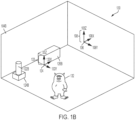
- FIG. 1B illustrates an example virtual environment 130 that corresponds to real environment 100.
- the virtual environment 130 shown comprises a virtual rectangular room 104B corresponding to real rectangular room 104A; a virtual object 122B corresponding to real object 122A; a virtual object 124B corresponding to real object 124A; and a virtual object 126B corresponding to real object 126A.
- Metadata associated with the virtual objects 122B, 124B, 126B can include information derived from the corresponding real objects 122A, 124A, 126A.
- Virtual environment 130 additionally comprises a virtual monster 132, which does not correspond to any real object in real environment 100.
- Real object 128A in real environment 100 does not correspond to any virtual object in virtual environment 130.
- a persistent coordinate system 133 (comprising an x-axis 133X, a y-axis 133Y, and a z-axis 133Z) with its origin at point 134 (persistent coordinate), can define a coordinate space for virtual content.
- the origin point 134 of the persistent coordinate system 133 may be defined relative/with respect to one or more real objects, such as the real object 126A.
- a matrix (which may include a translation matrix and a Quaternion matrix or other rotation matrix), or other suitable representation can characterize a transformation between the persistent coordinate system 133 space and the environment/world coordinate system 108 space.
- each of the virtual objects 122B, 124B, 126B, and 132 may have their own persistent coordinate point relative to the origin point 134 of the persistent coordinate system 133. In some embodiments, there may be multiple persistent coordinate systems and each of the virtual objects 122B, 124B, 126B, and 132 may have their own persistent coordinate point relative to one or more persistent coordinate systems.
- environment/world coordinate system 108 defines a shared coordinate space for both real environment 100 and virtual environment 130.
- the coordinate space has its origin at point 106.
- the coordinate space is defined by the same three orthogonal axes (108X, 108Y, 108Z). Accordingly, a first location in real environment 100, and a second, corresponding location in virtual environment 130, can be described with respect to the same coordinate space. This simplifies identifying and displaying corresponding locations in real and virtual environments, because the same coordinates can be used to identify both locations.
- corresponding real and virtual environments need not use a shared coordinate space.
- a matrix which may include a translation matrix and a Quaternion matrix or other rotation matrix
- suitable representation can characterize a transformation between a real environment coordinate space and a virtual environment coordinate space.
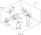
- FIG. 1C illustrates an example MRE 150 that simultaneously presents aspects of real environment 100 and virtual environment 130 to user 110 via mixed reality system 112.
- MRE 150 simultaneously presents user 110 with real objects 122A, 124A, 126A, and 128A from real environment 100 (e.g., via a transmissive portion of a display of mixed reality system 112); and virtual objects 122B, 124B, 126B, and 132 from virtual environment 130 (e.g., via an active display portion of the display of mixed reality system 112).
- origin point 106 acts as an origin for a coordinate space corresponding to MRE 150
- coordinate system 108 defines an x-axis, y-axis, and z-axis for the coordinate space.
- mixed reality objects comprise corresponding pairs of real objects and virtual objects (i.e., 122A/122B, 124A/124B, 126A/126B) that occupy corresponding locations in coordinate space 108.
- both the real objects and the virtual objects may be simultaneously visible to user 110. This may be desirable in, for example, instances where the virtual object presents information designed to augment a view of the corresponding real object (such as in a museum application where a virtual object presents the missing pieces of an ancient damaged sculpture).
- the virtual objects (122B, 124B, and/or 126B) may be displayed (e.g., via active pixelated occlusion using a pixelated occlusion shutter) so as to occlude the corresponding real objects (122A, 124A, and/or 126A). This may be desirable in, for example, instances where the virtual object acts as a visual replacement for the corresponding real object (such as in an interactive storytelling application where an inanimate real object becomes a "living" character).
- real objects may be associated with virtual content or helper data that may not necessarily constitute virtual objects.
- Virtual content or helper data can facilitate processing or handling of virtual objects in the mixed reality environment.
- virtual content could include two-dimensional representations of corresponding real objects; custom asset types associated with corresponding real objects; or statistical data associated with corresponding real objects. This information can enable or facilitate calculations involving a real object without incurring unnecessary computational overhead.
- the presentation described above may also incorporate audio aspects.
- virtual monster 132 could be associated with one or more audio signals, such as a footstep sound effect that is generated as the monster walks around MRE 150.
- a processor of mixed reality system 112 can compute an audio signal corresponding to a mixed and processed composite of all such sounds in MRE 150, and present the audio signal to user 110 via one or more speakers included in mixed reality system 112 and/or one or more external speakers.
- Example mixed reality system 112 can include a wearable head device (e.g., a wearable augmented reality or mixed reality head device) comprising a display (which may comprise left and right transmissive displays, which may be near-eye displays, and associated components for coupling light from the displays to the user's eyes); left and right speakers (e.g., positioned adjacent to the user's left and right ears, respectively); an inertial measurement unit (IMU)(e.g., mounted to a temple arm of the head device); an orthogonal coil electromagnetic receiver (e.g., mounted to the left temple piece); left and right cameras (e.g., depth (time-of-flight) cameras) oriented away from the user; and left and right eye cameras oriented toward the user (e.g., for detecting the user's eye movements).
- a wearable head device e.g., a wearable augmented reality or mixed reality head device
- a display which may comprise left and right transmissive displays, which may be near-eye displays, and associated
- a mixed reality system 112 can incorporate any suitable display technology, and any suitable sensors (e.g., optical, infrared, acoustic, LIDAR, EOG, GPS, magnetic).
- mixed reality system 112 may incorporate networking features (e.g., Wi-Fi capability) to communicate with other devices and systems, including other mixed reality systems.
- Mixed reality system 112 may further include a battery (which may be mounted in an auxiliary unit, such as a belt pack designed to be worn around a user's waist), a processor, and a memory.
- the wearable head device of mixed reality system 112 may include tracking components, such as an IMU or other suitable sensors, configured to output a set of coordinates of the wearable head device relative to the user's environment.
- tracking components may provide input to a processor performing a Simultaneous Localization and Mapping (SLAM) and/or visual odometry algorithm.
- mixed reality system 112 may also include a handheld controller 300, and/or an auxiliary unit 320, which may be a wearable beltpack, as described further below.
- FIGs. 2A-2D illustrate components of an example mixed reality system 200 (which may correspond to mixed reality system 112) that may be used to present a MRE (which may correspond to MRE 150), or other virtual environment, to a user.
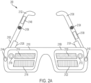
- FIG. 2A illustrates a perspective view of a wearable head device 2102 included in example mixed reality system 200.
- FIG. 2B illustrates a top view of wearable head device 2102 worn on a user's head 2202.
- FIG. 2C illustrates a front view of wearable head device 2102.
- FIG. 2D illustrates an edge view of example eyepiece 2110 of wearable head device 2102. As shown in FIGs.
- the example wearable head device 2102 includes an example left eyepiece (e.g., a left transparent waveguide set eyepiece) 2108 and an example right eyepiece (e.g., a right transparent waveguide set eyepiece) 2110.
- Each eyepiece 2108 and 2110 can include transmissive elements through which a real environment can be visible, as well as display elements for presenting a display (e.g., via imagewise modulated light) overlapping the real environment.
- display elements can include surface diffractive optical elements for controlling the flow of imagewise modulated light.
- the left eyepiece 2108 can include a left incoupling grating set 2112, a left orthogonal pupil expansion (OPE) grating set 2120, and a left exit (output) pupil expansion (EPE) grating set 2122.
- the right eyepiece 2110 can include a right incoupling grating set 2118, a right OPE grating set 2114 and a right EPE grating set 2116. Imagewise modulated light can be transferred to a user's eye via the incoupling gratings 2112 and 2118, OPEs 2114 and 2120, and EPE 2116 and 2122.
- Each incoupling grating set 2112, 2118 can be configured to deflect light toward its corresponding OPE grating set 2120, 2114.
- Each OPE grating set 2120, 2114 can be designed to incrementally deflect light down toward its associated EPE 2122, 2116, thereby horizontally extending an exit pupil being formed.
- Each EPE 2122, 2116 can be configured to incrementally redirect at least a portion of light received from its corresponding OPE grating set 2120, 2114 outward to a user eyebox position (not shown) defined behind the eyepieces 2108, 2110, vertically extending the exit pupil that is formed at the eyebox.
- the eyepieces 2108 and 2110 can include other arrangements of gratings and/or refractive and reflective features for controlling the coupling of imagewise modulated light to the user's eyes.
- wearable head device 2102 can include a left temple arm 2130 and a right temple arm 2132, where the left temple arm 2130 includes a left speaker 2134 and the right temple arm 2132 includes a right speaker 2136.
- An orthogonal coil electromagnetic receiver 2138 can be located in the left temple piece, or in another suitable location in the wearable head unit 2102.
- An Inertial Measurement Unit (IMU) 2140 can be located in the right temple arm 2132, or in another suitable location in the wearable head device 2102.
- the wearable head device 2102 can also include a left depth (e.g., time-of-flight) camera 2142 and a right depth camera 2144.
- the depth cameras 2142, 2144 can be suitably oriented in different directions so as to together cover a wider field of view.
- a left source of imagewise modulated light 2124 can be optically coupled into the left eyepiece 2108 through the left incoupling grating set 2112
- a right source of imagewise modulated light 2126 can be optically coupled into the right eyepiece 2110 through the right incoupling grating set 2118.
- Sources of imagewise modulated light 2124, 2126 can include, for example, optical fiber scanners; projectors including electronic light modulators such as Digital Light Processing (DLP) chips or Liquid Crystal on Silicon (LCoS) modulators; or emissive displays, such as micro Light Emitting Diode ( ⁇ LED) or micro Organic Light Emitting Diode ( ⁇ OLED) panels coupled into the incoupling grating sets 2112, 2118 using one or more lenses per side.
- the input coupling grating sets 2112, 2118 can deflect light from the sources of imagewise modulated light 2124, 2126 to angles above the critical angle for Total Internal Reflection (TIR) for the eyepieces 2108, 2110.
- TIR Total Internal Reflection
- the OPE grating sets 2114, 2120 incrementally deflect light propagating by TIR down toward the EPE grating sets 2116, 2122.
- the EPE grating sets 2116, 2122 incrementally couple light toward the user's face, including the pupils of the user's eyes.
- each of the left eyepiece 2108 and the right eyepiece 2110 includes a plurality of waveguides 2402.
- each eyepiece 2108, 2110 can include multiple individual waveguides, each dedicated to a respective color channel (e.g., red, blue and green).
- each eyepiece 2108, 2110 can include multiple sets of such waveguides, with each set configured to impart different wavefront curvature to emitted light.
- the wavefront curvature may be convex with respect to the user's eyes, for example to present a virtual object positioned a distance in front of the user (e.g., by a distance corresponding to the reciprocal of wavefront curvature).
- EPE grating sets 2116, 2122 can include curved grating grooves to effect convex wavefront curvature by altering the Poynting vector of exiting light across each EPE.
- stereoscopically-adjusted left and right eye imagery can be presented to the user through the imagewise light modulators 2124, 2126 and the eyepieces 2108, 2110.
- the perceived realism of a presentation of a three-dimensional virtual object can be enhanced by selecting waveguides (and thus corresponding the wavefront curvatures) such that the virtual object is displayed at a distance approximating a distance indicated by the stereoscopic left and right images.
- This technique may also reduce motion sickness experienced by some users, which may be caused by differences between the depth perception cues provided by stereoscopic left and right eye imagery, and the autonomic accommodation (e.g., object distance-dependent focus) of the human eye.
- FIG. 2D illustrates an edge-facing view from the top of the right eyepiece 2110 of example wearable head device 2102.
- the plurality of waveguides 2402 can include a first subset of three waveguides 2404 and a second subset of three waveguides 2406.
- the two subsets of waveguides 2404, 2406 can be differentiated by different EPE gratings featuring different grating line curvatures to impart different wavefront curvatures to exiting light.
- each waveguide can be used to couple a different spectral channel (e.g., one of red, green and blue spectral channels) to the user's right eye 2206.
- a different spectral channel e.g., one of red, green and blue spectral channels
- FIG. 3A illustrates an example handheld controller component 300 of a mixed reality system 200.
- handheld controller 300 includes a grip portion 346 and one or more buttons 350 disposed along a top surface 348.
- buttons 350 may be configured for use as an optical tracking target, e.g., for tracking six-degree-of-freedom (6DOF) motion of the handheld controller 300, in conjunction with a camera or other optical sensor (which may be mounted in a head unit (e.g., wearable head device 2102) of mixed reality system 200).
- handheld controller 300 includes tracking components (e.g., an IMU or other suitable sensors) for detecting position or orientation, such as position or orientation relative to wearable head device 2102.
- tracking components e.g., an IMU or other suitable sensors
- such tracking components may be positioned in a handle of handheld controller 300, and/or may be mechanically coupled to the handheld controller.
- Handheld controller 300 can be configured to provide one or more output signals corresponding to one or more of a pressed state of the buttons; or a position, orientation, and/or motion of the handheld controller 300 (e.g., via an IMU).
- Such output signals may be used as input to a processor of mixed reality system 200.
- Such input may correspond to a position, orientation, and/or movement of the handheld controller (and, by extension, to a position, orientation, and/or movement of a hand of a user holding the controller).
- Such input may also correspond to a user pressing buttons 350.
- FIG. 3B illustrates an example auxiliary unit 320 of a mixed reality system 200.
- the auxiliary unit 320 can include a battery to provide energy to operate the system 200, and can include a processor for executing programs to operate the system 200.
- the example auxiliary unit 320 includes a clip 2128, such as for attaching the auxiliary unit 320 to a user's belt.
- Other form factors are suitable for auxiliary unit 320 and will be apparent, including form factors that do not involve mounting the unit to a user's belt.
- auxiliary unit 320 is coupled to the wearable head device 2102 through a multiconduit cable that can include, for example, electrical wires and fiber optics. Wireless connections between the auxiliary unit 320 and the wearable head device 2102 can also be used.
- mixed reality system 200 can include one or more microphones to detect sound and provide corresponding signals to the mixed reality system.
- a microphone may be attached to, or integrated with, wearable head device 2102, and may be configured to detect a user's voice.
- a microphone may be attached to, or integrated with, handheld controller 300 and/or auxiliary unit 320. Such a microphone may be configured to detect environmental sounds, ambient noise, voices of a user or a third party, or other sounds.
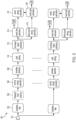
- FIG. 4 shows an example functional block diagram that may correspond to an example mixed reality system, such as mixed reality system 200 described above (which may correspond to mixed reality system 112 with respect to FIG. 1 ).
- example handheld controller 400B (which may correspond to handheld controller 300 (a "totem")) includes a totem-to-wearable head device six degree of freedom (6DOF) totem subsystem 404A and example wearable head device 400A (which may correspond to wearable head device 2102) includes a totem-to-wearable head device 6DOF subsystem 404B.
- 6DOF six degree of freedom
- the 6DOF totem subsystem 404A and the 6DOF subsystem 404B cooperate to determine six coordinates (e.g., offsets in three translation directions and rotation along three axes) of the handheld controller 400B relative to the wearable head device 400A.
- the six degrees of freedom may be expressed relative to a coordinate system of the wearable head device 400A.
- the three translation offsets may be expressed as X, Y, and Z offsets in such a coordinate system, as a translation matrix, or as some other representation.
- the rotation degrees of freedom may be expressed as sequence of yaw, pitch and roll rotations, as a rotation matrix, as a quaternion, or as some other representation.
- the wearable head device 400A; one or more depth cameras 444 (and/or one or more non-depth cameras) included in the wearable head device 400A; and/or one or more optical targets (e.g., buttons 350 of handheld controller 400B as described above, or dedicated optical targets included in the handheld controller 400B) can be used for 6DOF tracking.
- the handheld controller 400B can include a camera, as described above; and the wearable head device 400A can include an optical target for optical tracking in conjunction with the camera.
- the wearable head device 400A and the handheld controller 400B each include a set of three orthogonally oriented solenoids which are used to wirelessly send and receive three distinguishable signals.
- 6DOF totem subsystem 404A can include an Inertial Measurement Unit (IMU) that is useful to provide improved accuracy and/or more timely information on rapid movements of the handheld controller 400B.
- IMU Inertial Measurement Unit
- a local coordinate space e.g., a coordinate space fixed relative to the wearable head device 400A
- an inertial coordinate space e.g., a coordinate space fixed relative to the real environment
- such transformations may be necessary for a display of the wearable head device 400A to present a virtual object at an expected position and orientation relative to the real environment (e.g., a virtual person sitting in a real chair, facing forward, regardless of the wearable head device's position and orientation), rather than at a fixed position and orientation on the display (e.g., at the same position in the right lower corner of the display), to preserve the illusion that the virtual object exists in the real environment (and does not, for example, appear positioned unnaturally in the real environment as the wearable head device 400A shifts and rotates).
- an expected position and orientation relative to the real environment e.g., a virtual person sitting in a real chair, facing forward, regardless of the wearable head device's position and orientation
- a fixed position and orientation on the display e.g., at the same position in the right lower corner of the display
- a compensatory transformation between coordinate spaces can be determined by processing imagery from the depth cameras 444 using a SLAM and/or visual odometry procedure in order to determine the transformation of the wearable head device 400A relative to the coordinate system 108.
- the depth cameras 444 are coupled to a SLAM/visual odometry block 406 and can provide imagery to block 406.
- the SLAM/visual odometry block 406 implementation can include a processor configured to process this imagery and determine a position and orientation of the user's head, which can then be used to identify a transformation between a head coordinate space and another coordinate space (e.g., an inertial coordinate space).
- an additional source of information on the user's head pose and location is obtained from an IMU 409.
- Information from the IMU 409 can be integrated with information from the SLAM/visual odometry block 406 to provide improved accuracy and/or more timely information on rapid adjustments of the user's head pose and position.
- the depth cameras 444 can supply 3D imagery to a hand gesture tracker 411, which may be implemented in a processor of the wearable head device 400A.
- the hand gesture tracker 411 can identify a user's hand gestures, for example by matching 3D imagery received from the depth cameras 444 to stored patterns representing hand gestures. Other suitable techniques of identifying a user's hand gestures will be apparent.
- one or more processors 416 may be configured to receive data from the wearable head device's 6DOF headgear subsystem 404B, the IMU 409, the SLAM/visual odometry block 406, depth cameras 444, and/or the hand gesture tracker 411.
- the processor 416 can also send and receive control signals from the 6DOF totem system 404A.
- the processor 416 may be coupled to the 6DOF totem system 404A wirelessly, such as in examples where the handheld controller 400B is untethered.
- Processor 416 may further communicate with additional components, such as an audio-visual content memory 418, a Graphical Processing Unit (GPU) 420, and/or a Digital Signal Processor (DSP) audio spatializer 422.
- GPU Graphical Processing Unit
- DSP Digital Signal Processor
- the DSP audio spatializer 422 may be coupled to a Head Related Transfer Function (HRTF) memory 425.
- the GPU 420 can include a left channel output coupled to the left source of imagewise modulated light 424 and a right channel output coupled to the right source of imagewise modulated light 426.
- GPU 420 can output stereoscopic image data to the sources of imagewise modulated light 424, 426, for example as described above with respect to FIGs. 2A-2D .
- the DSP audio spatializer 422 can output audio to a left speaker 412 and/or a right speaker 414.
- the DSP audio spatializer 422 can receive input from processor 419 indicating a direction vector from a user to a virtual sound source (which may be moved by the user, e.g., via the handheld controller 320). Based on the direction vector, the DSP audio spatializer 422 can determine a corresponding HRTF (e.g., by accessing a HRTF, or by interpolating multiple HRTFs). The DSP audio spatializer 422 can then apply the determined HRTF to an audio signal, such as an audio signal corresponding to a virtual sound generated by a virtual object.
- auxiliary unit 400C may include a battery 427 to power its components and/or to supply power to the wearable head device 400A or handheld controller 400B. Including such components in an auxiliary unit, which can be mounted to a user's waist, can limit the size and weight of the wearable head device 400A, which can in turn reduce fatigue of a user's head and neck.
- FIG. 4 presents elements corresponding to various components of an example mixed reality system
- various other suitable arrangements of these components will become apparent to those skilled in the art.
- elements presented in FIG. 4 as being associated with auxiliary unit 400C could instead be associated with the wearable head device 400A or handheld controller 400B.
- some mixed reality systems may forgo entirely a handheld controller 400B or auxiliary unit 400C.
- Such changes and modifications are to be understood as being included within the scope of the disclosed examples.
- Presenting virtual audio content to a user can be advantageous in creating an immersive augmented/mixed reality experience.
- An immersive augmented/mixed reality experience can further blend real content with virtual content when convincing audio is presented in addition to convincing video.
- Displaying convincing virtual video content e.g., aligned with and/or inseparable from real content
- Displaying convincing virtual video content can further include rendering two sets of the same virtual video content from two different perspectives so that a stereoscopic image can be presented to a user to simulate three-dimensional virtual video content.
- presenting virtual audio content in a convincing matter can also include complex analyses of a real environment. For example, it can be desirable to understand acoustic properties of a real environment in which a MR system is being used so that virtual audio content can be rendered in a way that it simulates real audio content. Acoustic properties of a real environment can be used by a MR system (e.g., MR system 112, 200) to modify a rendering algorithm such that the virtual audio content sounds as if it originated from or otherwise belongs in the real environment. For example, a MR system used in a room with hard flooring and exposed walls may produce virtual audio content that mimics an echo that real audio content may have.
- a MR system used in a room with hard flooring and exposed walls may produce virtual audio content that mimics an echo that real audio content may have.
- Playing virtual audio content in a static manner as a user changes real environments may detract from an experience's immersion. It can be especially beneficial to render virtual audio content to mimic characteristics of real audio content if real audio content and virtual audio content may interact with each other (e.g., a user can speak to a virtual companion, and the virtual companion may speak back to the user). To do so, a MR system may determine acoustic characteristics of the real environment and apply those acoustic characteristics to virtual audio content (e.g., by altering a rendering algorithm for the virtual audio content). Additional details may be found in U.S. Patent Publication No. 2019116448 .
- a reverberation time can include a length of time required for a sound to decay by a certain amount (e.g., by 60 decibels). Sound decay can be a result of sound reflecting off surfaces in a real environment (e.g., walls, floors, furniture, etc.) whilst losing energy due to, for example, geometric spreading.
- a reverberation time can be influenced by environmental factors. For example, absorbent surfaces (e.g., cushions) may absorb sound in addition to geometric spreading, and a reverberation time may be reduced as a result. In some embodiments, it may not be necessary to have information about an original source to estimate an environment's reverberation time.
- a reverberation gain can include a ratio of a sound's direct/source/original energy to the sound's reverberation energy (e.g., energy of a reverberation resulting from the direct/source/original sound) where a listener and the source are substantially co-located (e.g., a user may clap their hands, producing a source sound that may be considered substantially co-located with one or more microphones mounted on a head-wearable MR system).
- a reverberation gain can include a ratio of a sound's direct/source/original energy to the sound's reverberation energy (e.g., energy of a reverberation resulting from the direct/source/original sound) where a listener and the source are substantially co-located (e.g., a user may clap their hands, producing a source sound that may be considered substantially co-located with one or more microphones mounted on a head-wearable MR system).
- an impulse e.g., a clap
- the reverberation sound from the impulse may have an energy associated with the reverberation of the impulse.
- the ratio of the original/source energy to the reverberation energy may be a reverberation gain.
- a real environment's reverberation gain may be influenced by, for example, absorbent surfaces that can absorb sound and thereby reduce a reverberation energy.
- a reverberation fingerprint can be passed to an audio rendering algorithm as one or more input parameters, which may allow the audio rendering algorithm to present virtual audio content with the same or similar characteristics as real audio content in a real environment.
- a reverberation fingerprint can be useful because it may characterize a real environment's acoustic properties independent of a sound source's position and/or orientation in the real environment.
- a standard interior room with four walls, a floor, and a ceiling may exhibit the same (or substantially the same) reverberation time and/or reverberation gain regardless if a source is located at a corner of the room, in the center of the room, or along any of the room's walls/edges.
- a sound source directly facing a corner of the room, the center of the room, or a wall in the room may all behave the same (or substantially the same) according to a real environment's reverberation fingerprint.
- a reverberation fingerprint can also be useful because it may characterize a real environment's acoustic properties independent of characteristics of a sound source. For example, a sound source (e.g., a person talking) at a low frequency, middle frequency, or high frequency may all behave the same (or substantially the same) according to a real environment's reverberation time and/or reverberation gain. Similarly, an impulse sound source (e.g., a clap) and a non-impulse sound source may behave the same (or substantially the same) according to a real environment's reverberation fingerprint (e.g., reverberation time and/or reverberation gain).
- a loud sound source and a quiet sound source may behave the same (or substantially the same) according to a real environment's reverberation fingerprint (e.g., reverberation time and/or reverberation gain).
- a reverberation fingerprint e.g., reverberation time and/or reverberation gain.
- the independence of a reverberation fingerprint from characteristics and/or location of a sound source can make the reverberation fingerprint a useful tool to render virtual audio content in a computationally efficient manner (e.g., the rendering algorithm can be the same as long as a user does not change environments, for example, by moving to a different room).
- a reverberation fingerprint may apply to "well-behaved" rooms (e.g., a standard interior room with four walls, a floor, and a ceiling), and may not apply to "misbehaved” rooms (e.g., a long corridor) that may have special acoustic properties.
- "well-behaved" rooms e.g., a standard interior room with four walls, a floor, and a ceiling
- “misbehaved” rooms e.g., a long corridor
- a blind estimation can be an estimation of a reverberation fingerprint where information about a sound source may not be required.
- a reverberation fingerprint may be estimated based simply on human conversation, where information on the original speech may not be provided to the estimation algorithm. Pauses during human speech can provide enough time for a reverberation fingerprint to be estimated using blind estimation. It can be beneficial to perform a blind estimation because such an estimation can be done without requiring a lengthy setup process and/or user interaction.
- a reverberation time can be blindly estimated and may not require information about an original sound source.
- a blind estimation may not be performed on a reverberation gain, which may include information about an original sound source.
- FIG. 5 illustrates an example process 500 of estimating a reverberation fingerprint, according to some embodiments.
- the example process shown can be implemented using one or more components of a mixed reality system, such as one or more of wearable head device 2102, handheld controller 300, and auxiliary unit 320 of the example mixed reality system 200 described above; or by a system (e.g., a system comprising a cloud server) in communication with mixed reality system 200.
- a system e.g., a system comprising a cloud server
- an input 501 can be split into one or more filtered components, which may then be individually processed.
- a bandpass filter can be applied to an input 501, which can be an audio signal from one or more microphones (e.g., one or more microphones mounted on a MR system).
- a bandpass filter can preferentially allow certain frequency ranges through the filter and/or suppress frequencies outside the frequency range.
- Bandpass filters can break a signal into smaller component pieces that may be easier to process for computational efficiency.
- Bandpass filters can also improve a signal-to-noise ratio of a signal by removing unwanted noise at frequencies outside the frequency range.
- bandpass filters can be used to separate an audio signal into six frequency ranges.
- a reverberation fingerprint (e.g., a reverberation time and a reverberation gain) can be estimated for each frequency range.
- each frequency can have an associated reverberation time and/or reverberation gain (e.g., a reverberation time and/or reverberation gain may be interpolated from calculated values that may be centered at a frequency range separated by a bandpass filter).
- a reverberation time and/or reverberation gain may be interpolated from calculated values that may be centered at a frequency range separated by a bandpass filter.
- an audio signal may be separated into any number of frequency ranges (e.g., using any number of bandpass filters).
- octave filters can be applied to the input signal.
- 1/3 octave filters can be applied to the input signal.
- signals with frequencies that are too low may not be analyzed for a reverberation fingerprint (e.g., because low frequencies may not sufficiently reverberate to conduct a reverberation fingerprint analysis).
- frequency band boosting can optionally be applied.
- Frequency band boosting may be applied to low frequencies (e.g., less than 500Hz) that may have a low signal-to-noise ratio, but the signal-to-noise ratio may still be sufficiently high to determine a reverberation fingerprint (e.g., the signal-to-noise ratio may be higher than a signal-to-noise ratio for frequencies less than 100Hz).
- Frequency band boosting may be applied to other frequency bands, or not at all.
- a running energy estimation can be performed on a signal.
- a running energy estimation can be performed in the frequency domain, time domain, spectral domain, and/or any other suitable domain.
- Signal energy may be estimated by determining an area under a squared magnitude of the signal in a time domain or by using other appropriate methods.
- envelope detection can be run on the signal and may be based on a running energy (estimate) of the signal.
- a signal envelope can be a characterization of signal peaks and/or troughs and may define upper and/or lower boundaries of a signal (e.g., an oscillating signal).
- Envelope detection can be performed using a Hilbert transform, a leaky integrator based root mean square detector, and/or other suitable methods.
- peak picking can be run on a signal envelope. Peak picking can identify local peaks in a signal envelope based on an amplitude of a previously detected peak and/or based on local maxima.
- a free decay region estimation can be run on a signal envelope.
- a free decay region can be a region of a signal envelope where the envelope decreases (e.g., after a local peak). This can be the result of a reverberation where new sound may not be detected and only previous sound continues to reverberate in a real environment, resulting in a decrease in the signal envelope.
- a linear fit can be determined for each of one or more free decay regions in a signal. A linear fit may be appropriate where a signal envelope is measured on a decibel scale due to an exponential decay of sound energy, and a decibel scale measuring on a logarithmic scale.
- a reverberation time can be estimated.
- a reverberation time may be estimated based on a free decay region or a portion of a free decay region with the fastest decaying slope, which can be determined from a linear fit determined for each free decay region (or portion of a free decay region).
- a threshold amount of time e.g., 50ms
- a linearly fitted slope can represent an amount by which the signal envelope decreases in decibels per unit of time (e.g., per second).
- multiple linear fits can be applied to a single free decay region.
- a linear regression may only be applied within a time range that the regression is sufficiently accurate (e.g., a correlation of 97% or greater). If a linear regression no longer fits the remainder of the duration of a free decay region, one or more additional/alternate linear regressions may be applied. Accuracy in a reverberation time estimate can be increased by using only the fastest decaying slope within a free decay region because the associated portion of the free decay region may most accurately represent only reverberant sounds.
- a portion of a free decay region with a slower decaying slope may capture a small amount of non-reverberant (e.g., original/source) sound, which may artificially slow a measured decay rate.
- a reverberation time (which can be a time required for a signal to decay by 60 decibels) can be extrapolated.
- FIG. 6 illustrates an example process 600 for estimating a reverberation time.
- Example process 600 may correspond to step 514 of example process 500 described above.
- Example process 600 can be implemented using one or more components of a mixed reality system, such as one or more of wearable head device 2102, handheld controller 300, and auxiliary unit 320 of the example mixed reality system 200 described above; or by a system (e.g., a system comprising a cloud server) in communication with mixed reality system 200.
- a local peak may be determined (e.g., a local peak from a signal envelope).
- a linear regression can be fit to part or all of a free decay region.
- a free decay region can be a region of a signal envelope where the envelope decreases (e.g., after a local peak).
- a linear regression may not account for a portion of time after a local peak (e.g., 50ms after a local peak).
- it can be determined whether the linear fit is sufficiently accurate e.g., has a sufficiently low root mean square error). If it is determined that the linear fit is not sufficiently accurate, at step 609 the next free decay region or portion of a free decay region may be examined. If it is determined that the linear fit is sufficiently accurate, at step 610 it can be determined if the decay region occurs over a sufficiently long period of time (e.g., >400ms).
- the next free decay region or portion of a free decay region may be examined at step 609. If it is determined that the decay region does occur over a sufficiently long period of time, at step 612 it can be determined if the decay slope from the linear regression is the fastest decay slope for the entire free decay region. If it is determined that the decay slope is not the fastest decay slope for the entire free decay region, the next free decay region or portion of a free decay region can be examined at step 609. If it is determined that the decay slope is the fastest decay slope for the entire free decay region, a reverberation time can be extrapolated based on the fastest decay slope at step 614.
- a reverberation time can be estimated using converging (or approximately converging) measurements. For example, a reverberation time can be declared after a threshold number of consecutive free decay regions have decay slopes within a threshold value of each other. An average decay slope may then be determined and declared as a reverberation time.
- decay slopes associated with free decay regions can be weighted according to a quality estimate for each measured decay slope.
- a decay slope may be determined to be more accurate when an associated portion of a free decay region lasts for a threshold amount of time (e.g., 400ms), which can increase an accuracy of the decay slope estimation.
- a decay slope may be determined to be more accurate if it has a relatively accurate linear fit (e.g., a low root mean square error). Decay slopes that are more accurate can be assigned higher weights in a weighted average to determine a reverberation time. In some embodiments, a single decay slope that is determined to be the most accurate (e.g., based on decay length and/or linear fit accuracy) can be used to determine a reverberation time, which may be a reverberation time for a given frequency range (e.g., a frequency range selected by a bandpass filter at step 502).
- a time difference between the reverberation time and a previously estimated reverberation time is determined. It is also determined whether the time difference is greater than a time threshold, and in accordance with a determination that the time difference is greater than the time threshold, the reverberation time estimate is declared.
- a confidence value may be determined and associated with a reverberation time. A confidence value may be determined based on various factors. For example, a confidence value can be based on a number of convergent decay slopes, a linear fit accuracy of utilized decay slopes, a decay length of utilized decay slopes, or any combination of these and/or other factors.
- a reverberation time estimate with an associated confidence may not be declared if the confidence value is below a threshold value (e.g., because insufficient free decay regions were detected for convergence). If a reverberation time estimate is not declared, other reverberation time estimates for other frequency ranges (e.g., frequency ranges separated at step 502 using a bandpass filter) may still be declared (e.g., if those reverberation time estimates have sufficiently high confidence values). The reverberation time estimate for a missing frequency range may be interpolated from declared reverberation times at other frequency ranges.
- a direct sound energy estimation can be performed.
- a direct sound energy estimation may utilize information on the direct/source sound. For example, if a direct/source sound is known, a direct sound energy estimation can estimate the energy of the direct/source sound (e.g., by integrating an area under a signal envelope peak including the direct/source sound). This can be achieved by using impulse sounds, which may be easier to separate a direct/source sound from a reverberant sound.
- a user may be prompted (e.g., by a MR system) to clap their hands to produce an impulse sound.
- a speaker for example one that is mounted on an MR system, may play an impulse sound.
- an impulse sound can be used to estimate both a direct sound energy and a reverberation time estimate.
- a direct sound estimation can be blindly estimated (e.g., if a blind estimate can separate a direct/source sound from a reverberant sound without prior knowledge of the direct/source sound).
- a reverberation sound energy can be estimated.
- the reverberation sound energy can be estimated by integrating a signal envelope from an end of a direct/source sound until the reverberant sound is no longer detected and/or the reverberant sound falls below a certain gain threshold (e.g., -90dB).
- a reverberation gain can be estimated based on the direct sound energy estimation and the reverberation energy estimation.
- the reverberation gain is calculated by taking a ratio of the reverberation energy to the direct sound energy.
- the reverberation gain is calculated by taking a ratio of the direct sound energy to the reverberation energy.
- a reverberation gain estimate can be declared (e.g., passed to an audio rendering algorithm).
- a confidence level may be associated with a reverberation gain estimate.
- a reverberation gain estimate may only be declared if a confidence level is at or above a certain threshold.
- a MR system may blindly estimate a reverberation time in the second room, determine that the reverberation time is sufficiently different than a previously declared reverberation time, and conclude that the user has changed rooms.
- a MR system may then declare a new reverberation time and/or a new reverberation gain (e.g., by asking the user to clap again, by playing an impulse through an external speaker, and/or doing a blind estimate of the reverberation gain).
- a user may calibrate a MR system in a room, and the MR system may determine a reverberation fingerprint of the room.
- the MR system may then identify the room based on the reverberation fingerprint and/or other factors (e.g., location determined through GPS and/or WiFi networks, or via one or more sensors such as described above with respect to the example mixed reality system 200).
- the MR system may access a remote database of previously mapped rooms and, using the reverberation fingerprint and/or other factors, identify the room as previously mapped.
- the MR system may download assets related to the room (e.g., a previously generated three-dimensional map of the room).
- FIG. 7 illustrates an example process for identifying a change in acoustic properties of a real environment.
- the example process shown can be implemented using one or more components of a mixed reality system, such as one or more of wearable head device 2102, handheld controller 300, and auxiliary unit 320 of the example mixed reality system 200 described above; or by a system (e.g., a system comprising a cloud server) in communication with mixed reality system 200.
- a new reverberation time can be determined (e.g., using process 500 and/or process 600).
- the new reverberation time can be compared to a previously declared reverberation time.
- a difference may be sufficient if a new reverberation time for a frequency range has a difference from a declared reverberation time for the frequency range greater than a specified threshold (e.g., 10%, which may be a sufficient difference for human listeners to perceive a difference).
- a sufficient difference may be determined if a threshold number of reverberation times for given frequency ranges differs from a threshold number of declared reverberation times for those frequency ranges.
- an absolute value of a difference between a new frequency response curve (which can include interpolated points between declared reverberation times for tested frequency ranges) and a declared frequency response curve can be integrated. If the integrated area is above a certain threshold, it may be determined that the new reverberation times are sufficiently different from the declared reverberation times.
- a MR system may continue to determine new reverberation times at step 702. If the new reverberation time is determined to be sufficiently different from a declared reverberation time, at step 708 it can be determined if a sufficient number of sufficiently different reverberation times has been detected. For example, three consecutive reverberation time estimates that are all sufficiently different from a declared reverberation item for a given frequency range may be a sufficient number of sufficiently different reverberation times. Other thresholds may also be used (e.g., three out of five most recent reverberation time estimates).
- step 710 can also include initiating a new reverberation gain estimate, which can prompt a user to clap or play an impulse sound from an external speaker.
- step 710 can also include accessing a remote database to identify a new real environment based on the new reverberation fingerprint and/or other information available to a MR system (e.g., location determined from GPS and/or WiFi connections, or via one or more sensors such as described above with respect to the example mixed reality system 200).
- a MR system e.g., location determined from GPS and/or WiFi connections, or via one or more sensors such as described above with respect to the example mixed reality system 200.
Landscapes
- Engineering & Computer Science (AREA)
- Physics & Mathematics (AREA)
- General Engineering & Computer Science (AREA)
- Theoretical Computer Science (AREA)
- Acoustics & Sound (AREA)
- Signal Processing (AREA)
- General Physics & Mathematics (AREA)
- Human Computer Interaction (AREA)
- Health & Medical Sciences (AREA)
- General Health & Medical Sciences (AREA)
- Otolaryngology (AREA)
- User Interface Of Digital Computer (AREA)
- Processing Or Creating Images (AREA)
- Circuit For Audible Band Transducer (AREA)
Applications Claiming Priority (2)
| Application Number | Priority Date | Filing Date | Title |
|---|---|---|---|
| US201962926330P | 2019-10-25 | 2019-10-25 | |
| PCT/US2020/057203 WO2021081435A1 (en) | 2019-10-25 | 2020-10-23 | Reverberation fingerprint estimation |
Publications (3)
| Publication Number | Publication Date |
|---|---|
| EP4049466A1 EP4049466A1 (en) | 2022-08-31 |
| EP4049466A4 EP4049466A4 (en) | 2022-12-28 |
| EP4049466B1 true EP4049466B1 (en) | 2025-04-30 |
Family
ID=75586525
Family Applications (1)
| Application Number | Title | Priority Date | Filing Date |
|---|---|---|---|
| EP20880077.1A Active EP4049466B1 (en) | 2019-10-25 | 2020-10-23 | Methods and systems for determining and processing audio information in a mixed reality environment |
Country Status (5)
| Country | Link |
|---|---|
| US (5) | US11304017B2 (https=) |
| EP (1) | EP4049466B1 (https=) |
| JP (2) | JP7446420B2 (https=) |
| CN (1) | CN114586382B (https=) |
| WO (1) | WO2021081435A1 (https=) |
Families Citing this family (54)
| Publication number | Priority date | Publication date | Assignee | Title |
|---|---|---|---|---|
| US9318108B2 (en) | 2010-01-18 | 2016-04-19 | Apple Inc. | Intelligent automated assistant |
| US8977255B2 (en) | 2007-04-03 | 2015-03-10 | Apple Inc. | Method and system for operating a multi-function portable electronic device using voice-activation |
| US8676904B2 (en) | 2008-10-02 | 2014-03-18 | Apple Inc. | Electronic devices with voice command and contextual data processing capabilities |
| US10057736B2 (en) | 2011-06-03 | 2018-08-21 | Apple Inc. | Active transport based notifications |
| US10417037B2 (en) | 2012-05-15 | 2019-09-17 | Apple Inc. | Systems and methods for integrating third party services with a digital assistant |
| DE112014000709B4 (de) | 2013-02-07 | 2021-12-30 | Apple Inc. | Verfahren und vorrichtung zum betrieb eines sprachtriggers für einen digitalen assistenten |
| US9715875B2 (en) | 2014-05-30 | 2017-07-25 | Apple Inc. | Reducing the need for manual start/end-pointing and trigger phrases |
| US10170123B2 (en) | 2014-05-30 | 2019-01-01 | Apple Inc. | Intelligent assistant for home automation |
| US9338493B2 (en) | 2014-06-30 | 2016-05-10 | Apple Inc. | Intelligent automated assistant for TV user interactions |
| US9886953B2 (en) | 2015-03-08 | 2018-02-06 | Apple Inc. | Virtual assistant activation |
| US10460227B2 (en) | 2015-05-15 | 2019-10-29 | Apple Inc. | Virtual assistant in a communication session |
| US10331312B2 (en) | 2015-09-08 | 2019-06-25 | Apple Inc. | Intelligent automated assistant in a media environment |
| US10671428B2 (en) | 2015-09-08 | 2020-06-02 | Apple Inc. | Distributed personal assistant |
| US10747498B2 (en) | 2015-09-08 | 2020-08-18 | Apple Inc. | Zero latency digital assistant |
| US11587559B2 (en) | 2015-09-30 | 2023-02-21 | Apple Inc. | Intelligent device identification |
| US10691473B2 (en) | 2015-11-06 | 2020-06-23 | Apple Inc. | Intelligent automated assistant in a messaging environment |
| US12223282B2 (en) | 2016-06-09 | 2025-02-11 | Apple Inc. | Intelligent automated assistant in a home environment |
| US10586535B2 (en) | 2016-06-10 | 2020-03-10 | Apple Inc. | Intelligent digital assistant in a multi-tasking environment |
| US12197817B2 (en) | 2016-06-11 | 2025-01-14 | Apple Inc. | Intelligent device arbitration and control |
| DK201670540A1 (en) | 2016-06-11 | 2018-01-08 | Apple Inc | Application integration with a digital assistant |
| US11204787B2 (en) | 2017-01-09 | 2021-12-21 | Apple Inc. | Application integration with a digital assistant |
| DK180048B1 (en) | 2017-05-11 | 2020-02-04 | Apple Inc. | MAINTAINING THE DATA PROTECTION OF PERSONAL INFORMATION |
| DK201770428A1 (en) | 2017-05-12 | 2019-02-18 | Apple Inc. | LOW-LATENCY INTELLIGENT AUTOMATED ASSISTANT |
| DK179496B1 (en) | 2017-05-12 | 2019-01-15 | Apple Inc. | USER-SPECIFIC Acoustic Models |
| DK201770411A1 (en) | 2017-05-15 | 2018-12-20 | Apple Inc. | Multi-modal interfaces |
| DK179560B1 (en) | 2017-05-16 | 2019-02-18 | Apple Inc. | FAR-FIELD EXTENSION FOR DIGITAL ASSISTANT SERVICES |
| US10303715B2 (en) | 2017-05-16 | 2019-05-28 | Apple Inc. | Intelligent automated assistant for media exploration |
| KR102785218B1 (ko) | 2017-10-17 | 2025-03-21 | 매직 립, 인코포레이티드 | 혼합 현실 공간 오디오 |
| CN116781827A (zh) | 2018-02-15 | 2023-09-19 | 奇跃公司 | 混合现实虚拟混响 |
| US10818288B2 (en) | 2018-03-26 | 2020-10-27 | Apple Inc. | Natural assistant interaction |
| US11145294B2 (en) | 2018-05-07 | 2021-10-12 | Apple Inc. | Intelligent automated assistant for delivering content from user experiences |
| US10928918B2 (en) | 2018-05-07 | 2021-02-23 | Apple Inc. | Raise to speak |
| DK180639B1 (en) | 2018-06-01 | 2021-11-04 | Apple Inc | DISABILITY OF ATTENTION-ATTENTIVE VIRTUAL ASSISTANT |
| DK201870355A1 (en) | 2018-06-01 | 2019-12-16 | Apple Inc. | VIRTUAL ASSISTANT OPERATION IN MULTI-DEVICE ENVIRONMENTS |
| CN119864004A (zh) | 2018-06-14 | 2025-04-22 | 奇跃公司 | 混响增益归一化 |
| US11462215B2 (en) | 2018-09-28 | 2022-10-04 | Apple Inc. | Multi-modal inputs for voice commands |
| US11348573B2 (en) | 2019-03-18 | 2022-05-31 | Apple Inc. | Multimodality in digital assistant systems |
| DK201970509A1 (en) | 2019-05-06 | 2021-01-15 | Apple Inc | Spoken notifications |
| US11307752B2 (en) | 2019-05-06 | 2022-04-19 | Apple Inc. | User configurable task triggers |
| US11140099B2 (en) | 2019-05-21 | 2021-10-05 | Apple Inc. | Providing message response suggestions |
| US11227599B2 (en) | 2019-06-01 | 2022-01-18 | Apple Inc. | Methods and user interfaces for voice-based control of electronic devices |
| EP4049466B1 (en) | 2019-10-25 | 2025-04-30 | Magic Leap, Inc. | Methods and systems for determining and processing audio information in a mixed reality environment |
| GB2588801A (en) | 2019-11-08 | 2021-05-12 | Nokia Technologies Oy | Determination of sound source direction |
| US11290834B2 (en) * | 2020-03-04 | 2022-03-29 | Apple Inc. | Determining head pose based on room reverberation |
| US12301635B2 (en) | 2020-05-11 | 2025-05-13 | Apple Inc. | Digital assistant hardware abstraction |
| US11061543B1 (en) | 2020-05-11 | 2021-07-13 | Apple Inc. | Providing relevant data items based on context |
| US11490204B2 (en) | 2020-07-20 | 2022-11-01 | Apple Inc. | Multi-device audio adjustment coordination |
| US11438683B2 (en) | 2020-07-21 | 2022-09-06 | Apple Inc. | User identification using headphones |
| US20230319465A1 (en) * | 2020-08-04 | 2023-10-05 | Rafael Chinchilla | Systems, Devices and Methods for Multi-Dimensional Audio Recording and Playback |
| US11630509B2 (en) * | 2020-12-11 | 2023-04-18 | Microsoft Technology Licensing, Llc | Determining user intent based on attention values |
| US20240414492A1 (en) * | 2021-10-25 | 2024-12-12 | Magic Leap, Inc. | Mapping of enviromental audio response on mixed reality device |
| CN115512720B (zh) * | 2022-09-14 | 2025-12-23 | 中科猷声(苏州)科技有限公司 | 用于远程通信的语音质量评价方法、装置及系统 |
| CN115855227B (zh) * | 2022-12-08 | 2026-03-24 | 广州声博士技术股份有限公司 | 一种混响时间测量方法、系统、设备及介质 |
| US12598442B2 (en) | 2023-01-09 | 2026-04-07 | Samsung Electronics Co., Ltd. | Automatic loudspeaker directivity adaptation |
Family Cites Families (155)
| Publication number | Priority date | Publication date | Assignee | Title |
|---|---|---|---|---|
| JPS5264974A (en) * | 1975-11-25 | 1977-05-28 | Victor Co Of Japan Ltd | Reverberation time measuring device |
| JPS644200A (en) * | 1987-06-26 | 1989-01-09 | Nissan Motor | Sound field improving device |
| US4852988A (en) | 1988-09-12 | 1989-08-01 | Applied Science Laboratories | Visor and camera providing a parallax-free field-of-view image for a head-mounted eye movement measurement system |
| GB9107011D0 (en) * | 1991-04-04 | 1991-05-22 | Gerzon Michael A | Illusory sound distance control method |
| FR2688371B1 (fr) | 1992-03-03 | 1997-05-23 | France Telecom | Procede et systeme de spatialisation artificielle de signaux audio-numeriques. |
| FR2738099B1 (fr) | 1995-08-25 | 1997-10-24 | France Telecom | Procede de simulation de la qualite acoustique d'une salle et processeur audio-numerique associe |
| US6847336B1 (en) | 1996-10-02 | 2005-01-25 | Jerome H. Lemelson | Selectively controllable heads-up display system |
| US6453047B1 (en) | 1998-09-28 | 2002-09-17 | Creative Technology Ltd | Matrix encoding system with improved behavior frequency |
| US6665407B1 (en) | 1998-09-28 | 2003-12-16 | Creative Technology Ltd. | Three channel panning system |
| US6188769B1 (en) | 1998-11-13 | 2001-02-13 | Creative Technology Ltd. | Environmental reverberation processor |
| US6433760B1 (en) | 1999-01-14 | 2002-08-13 | University Of Central Florida | Head mounted display with eyetracking capability |
| US6491391B1 (en) | 1999-07-02 | 2002-12-10 | E-Vision Llc | System, apparatus, and method for reducing birefringence |
| CA2316473A1 (en) | 1999-07-28 | 2001-01-28 | Steve Mann | Covert headworn information display or data display or viewfinder |
| US7231054B1 (en) | 1999-09-24 | 2007-06-12 | Creative Technology Ltd | Method and apparatus for three-dimensional audio display |
| US6798889B1 (en) | 1999-11-12 | 2004-09-28 | Creative Technology Ltd. | Method and apparatus for multi-channel sound system calibration |
| US6978027B1 (en) | 2000-04-11 | 2005-12-20 | Creative Technology Ltd. | Reverberation processor for interactive audio applications |
| US7149314B2 (en) | 2000-12-04 | 2006-12-12 | Creative Technology Ltd | Reverberation processor based on absorbent all-pass filters |
| US7099482B1 (en) | 2001-03-09 | 2006-08-29 | Creative Technology Ltd | Method and apparatus for the simulation of complex audio environments |
| CA2362895A1 (en) | 2001-06-26 | 2002-12-26 | Steve Mann | Smart sunglasses or computer information display built into eyewear having ordinary appearance, possibly with sight license |
| DE10132872B4 (de) | 2001-07-06 | 2018-10-11 | Volkswagen Ag | Kopfmontiertes optisches Durchsichtssystem |
| US20030030597A1 (en) | 2001-08-13 | 2003-02-13 | Geist Richard Edwin | Virtual display apparatus for mobile activities |
| US7848531B1 (en) | 2002-01-09 | 2010-12-07 | Creative Technology Ltd. | Method and apparatus for audio loudness and dynamics matching |
| JP4059478B2 (ja) * | 2002-02-28 | 2008-03-12 | パイオニア株式会社 | 音場制御方法及び音場制御システム |
| JP4055054B2 (ja) | 2002-05-15 | 2008-03-05 | ソニー株式会社 | 音響処理装置 |
| US7567845B1 (en) | 2002-06-04 | 2009-07-28 | Creative Technology Ltd | Ambience generation for stereo signals |
| US7257231B1 (en) | 2002-06-04 | 2007-08-14 | Creative Technology Ltd. | Stream segregation for stereo signals |
| CA2388766A1 (en) | 2002-06-17 | 2003-12-17 | Steve Mann | Eyeglass frames based computer display or eyeglasses with operationally, actually, or computationally, transparent frames |
| US6943754B2 (en) | 2002-09-27 | 2005-09-13 | The Boeing Company | Gaze tracking system, eye-tracking assembly and an associated method of calibration |
| US7347551B2 (en) | 2003-02-13 | 2008-03-25 | Fergason Patent Properties, Llc | Optical system for monitoring eye movement |
| US7500747B2 (en) | 2003-10-09 | 2009-03-10 | Ipventure, Inc. | Eyeglasses with electrical components |
| JP4349972B2 (ja) * | 2003-05-26 | 2009-10-21 | パナソニック株式会社 | 音場測定装置 |
| US7412380B1 (en) | 2003-12-17 | 2008-08-12 | Creative Technology Ltd. | Ambience extraction and modification for enhancement and upmix of audio signals |
| US7970144B1 (en) | 2003-12-17 | 2011-06-28 | Creative Technology Ltd | Extracting and modifying a panned source for enhancement and upmix of audio signals |
| CA2561287C (en) | 2004-04-01 | 2017-07-11 | William C. Torch | Biosensors, communicators, and controllers monitoring eye movement and methods for using them |
| WO2006003957A1 (ja) * | 2004-06-30 | 2006-01-12 | Pioneer Corporation | 残響調整装置、残響調整方法、残響調整プログラムおよびそれを記録した記録媒体、並びに、音場補正システム |
| US7928311B2 (en) | 2004-12-01 | 2011-04-19 | Creative Technology Ltd | System and method for forming and rendering 3D MIDI messages |
| US8964997B2 (en) | 2005-05-18 | 2015-02-24 | Bose Corporation | Adapted audio masking |
| US8696113B2 (en) | 2005-10-07 | 2014-04-15 | Percept Technologies Inc. | Enhanced optical and perceptual digital eyewear |
| US20070081123A1 (en) | 2005-10-07 | 2007-04-12 | Lewis Scott W | Digital eyewear |
| GB2431839B (en) | 2005-10-28 | 2010-05-19 | Sony Uk Ltd | Audio processing |
| US9788757B2 (en) | 2005-12-28 | 2017-10-17 | Breath Research, Inc. | Breathing biofeedback device |
| DE602006001051T2 (de) | 2006-01-09 | 2009-07-02 | Honda Research Institute Europe Gmbh | Bestimmung des entsprechenden Messfensters zur Schallquellenortung in Echoumgebungen |
| SG135058A1 (en) | 2006-02-14 | 2007-09-28 | St Microelectronics Asia | Digital audio signal processing method and system for generating and controlling digital reverberations for audio signals |
| US8379868B2 (en) | 2006-05-17 | 2013-02-19 | Creative Technology Ltd | Spatial audio coding based on universal spatial cues |
| US8345899B2 (en) | 2006-05-17 | 2013-01-01 | Creative Technology Ltd | Phase-amplitude matrixed surround decoder |
| US8712061B2 (en) | 2006-05-17 | 2014-04-29 | Creative Technology Ltd | Phase-amplitude 3-D stereo encoder and decoder |
| US8374365B2 (en) | 2006-05-17 | 2013-02-12 | Creative Technology Ltd | Spatial audio analysis and synthesis for binaural reproduction and format conversion |
| US8619998B2 (en) | 2006-08-07 | 2013-12-31 | Creative Technology Ltd | Spatial audio enhancement processing method and apparatus |
| US9014377B2 (en) | 2006-05-17 | 2015-04-21 | Creative Technology Ltd | Multichannel surround format conversion and generalized upmix |
| US9697844B2 (en) | 2006-05-17 | 2017-07-04 | Creative Technology Ltd | Distributed spatial audio decoder |
| US9496850B2 (en) | 2006-08-04 | 2016-11-15 | Creative Technology Ltd | Alias-free subband processing |
| US8488796B2 (en) | 2006-08-08 | 2013-07-16 | Creative Technology Ltd | 3D audio renderer |
| US8107631B2 (en) | 2007-10-04 | 2012-01-31 | Creative Technology Ltd | Correlation-based method for ambience extraction from two-channel audio signals |
| JP2009139615A (ja) | 2007-12-06 | 2009-06-25 | Toyama Univ | 音響再生装置、音響再生方法、音響再生プログラム、及び音響再生システム |
| JP5077847B2 (ja) * | 2008-03-04 | 2012-11-21 | 国立大学法人北陸先端科学技術大学院大学 | 残響時間推定装置及び残響時間推定方法 |
| JP2009290825A (ja) * | 2008-06-02 | 2009-12-10 | Yamaha Corp | 音響エコーキャンセラ |
| US9037468B2 (en) | 2008-10-27 | 2015-05-19 | Sony Computer Entertainment Inc. | Sound localization for user in motion |
| US8000485B2 (en) | 2009-06-01 | 2011-08-16 | Dts, Inc. | Virtual audio processing for loudspeaker or headphone playback |
| US9432790B2 (en) * | 2009-10-05 | 2016-08-30 | Microsoft Technology Licensing, Llc | Real-time sound propagation for dynamic sources |
| EP2486654B1 (en) | 2009-10-09 | 2016-09-21 | DTS, Inc. | Adaptive dynamic range enhancement of audio recordings |
| CN102667918B (zh) | 2009-10-21 | 2015-08-12 | 弗兰霍菲尔运输应用研究公司 | 用于使音频信号混响的混响器和方法 |
| WO2010000878A2 (en) * | 2009-10-27 | 2010-01-07 | Phonak Ag | Speech enhancement method and system |
| US20110213664A1 (en) | 2010-02-28 | 2011-09-01 | Osterhout Group, Inc. | Local advertising content on an interactive head-mounted eyepiece |
| US8890946B2 (en) | 2010-03-01 | 2014-11-18 | Eyefluence, Inc. | Systems and methods for spatially controlled scene illumination |
| KR20130038857A (ko) | 2010-04-09 | 2013-04-18 | 디티에스, 인코포레이티드 | 오디오 재생을 위한 적응적 주변 소음 보상 |
| JP5572445B2 (ja) | 2010-04-30 | 2014-08-13 | 本田技研工業株式会社 | 残響抑圧装置、及び残響抑圧方法 |
| US8531355B2 (en) | 2010-07-23 | 2013-09-10 | Gregory A. Maltz | Unitized, vision-controlled, wireless eyeglass transceiver |
| US8908874B2 (en) | 2010-09-08 | 2014-12-09 | Dts, Inc. | Spatial audio encoding and reproduction |
| US9391579B2 (en) | 2010-09-10 | 2016-07-12 | Dts, Inc. | Dynamic compensation of audio signals for improved perceived spectral imbalances |
| US8767968B2 (en) | 2010-10-13 | 2014-07-01 | Microsoft Corporation | System and method for high-precision 3-dimensional audio for augmented reality |
| US9292973B2 (en) | 2010-11-08 | 2016-03-22 | Microsoft Technology Licensing, Llc | Automatic variable virtual focus for augmented reality displays |
| WO2012093352A1 (en) | 2011-01-05 | 2012-07-12 | Koninklijke Philips Electronics N.V. | An audio system and method of operation therefor |
| CN103649706B (zh) | 2011-03-16 | 2015-11-25 | Dts(英属维尔京群岛)有限公司 | 三维音频音轨的编码及再现 |
| US9323325B2 (en) | 2011-08-30 | 2016-04-26 | Microsoft Technology Licensing, Llc | Enhancing an object of interest in a see-through, mixed reality display device |
| US9253574B2 (en) | 2011-09-13 | 2016-02-02 | Dts, Inc. | Direct-diffuse decomposition |
| US20130077147A1 (en) | 2011-09-22 | 2013-03-28 | Los Alamos National Security, Llc | Method for producing a partially coherent beam with fast pattern update rates |
| US8929589B2 (en) | 2011-11-07 | 2015-01-06 | Eyefluence, Inc. | Systems and methods for high-resolution gaze tracking |
| US8611015B2 (en) | 2011-11-22 | 2013-12-17 | Google Inc. | User interface |
| US8235529B1 (en) | 2011-11-30 | 2012-08-07 | Google Inc. | Unlocking a screen using eye tracking information |
| US10013053B2 (en) | 2012-01-04 | 2018-07-03 | Tobii Ab | System for gaze interaction |
| US8638498B2 (en) | 2012-01-04 | 2014-01-28 | David D. Bohn | Eyebox adjustment for interpupillary distance |
| US8831255B2 (en) | 2012-03-08 | 2014-09-09 | Disney Enterprises, Inc. | Augmented reality (AR) audio with position and action triggered virtual sound effects |
| US9274338B2 (en) | 2012-03-21 | 2016-03-01 | Microsoft Technology Licensing, Llc | Increasing field of view of reflective waveguide |
| WO2013181272A2 (en) | 2012-05-31 | 2013-12-05 | Dts Llc | Object-based audio system using vector base amplitude panning |
| US9332373B2 (en) | 2012-05-31 | 2016-05-03 | Dts, Inc. | Audio depth dynamic range enhancement |
| US8989535B2 (en) | 2012-06-04 | 2015-03-24 | Microsoft Technology Licensing, Llc | Multiple waveguide imaging structure |
| JP5417491B2 (ja) | 2012-06-27 | 2014-02-12 | 株式会社東芝 | 電子機器、方法およびプログラム |
| US9386373B2 (en) | 2012-07-03 | 2016-07-05 | Dts, Inc. | System and method for estimating a reverberation time |
| JP6003355B2 (ja) | 2012-07-30 | 2016-10-05 | ヤマハ株式会社 | 残響時間解析装置 |
| US9779731B1 (en) | 2012-08-20 | 2017-10-03 | Amazon Technologies, Inc. | Echo cancellation based on shared reference signals |
| CN104956689B (zh) * | 2012-11-30 | 2017-07-04 | Dts(英属维尔京群岛)有限公司 | 用于个性化音频虚拟化的方法和装置 |
| EP2929413B1 (en) | 2012-12-06 | 2020-06-03 | Google LLC | Eye tracking wearable devices and methods for use |
| KR20150103723A (ko) | 2013-01-03 | 2015-09-11 | 메타 컴퍼니 | 가상 또는 증강매개된 비전을 위한 엑스트라미시브 공간 이미징 디지털 아이 글래스 |
| US20140195918A1 (en) | 2013-01-07 | 2014-07-10 | Steven Friedlander | Eye tracking user interface |
| JP6519877B2 (ja) * | 2013-02-26 | 2019-05-29 | 聯發科技股▲ふん▼有限公司Mediatek Inc. | 音声信号を発生するための方法及び装置 |
| US9197930B2 (en) | 2013-03-15 | 2015-11-24 | The Nielsen Company (Us), Llc | Methods and apparatus to detect spillover in an audience monitoring system |
| US9443354B2 (en) | 2013-04-29 | 2016-09-13 | Microsoft Technology Licensing, Llc | Mixed reality interactions |
| KR20160005695A (ko) | 2013-04-30 | 2016-01-15 | 인텔렉추얼디스커버리 주식회사 | 헤드 마운트 디스플레이 및 이를 이용한 오디오 콘텐츠 제공 방법 |
| US10262462B2 (en) | 2014-04-18 | 2019-04-16 | Magic Leap, Inc. | Systems and methods for augmented and virtual reality |
| CN103675104B (zh) * | 2013-11-26 | 2015-12-02 | 同济大学 | 材料无规入射吸声系数或吸声量的测量方法及其测量装置 |
| US10063207B2 (en) | 2014-02-27 | 2018-08-28 | Dts, Inc. | Object-based audio loudness management |
| JP6349899B2 (ja) * | 2014-04-14 | 2018-07-04 | ヤマハ株式会社 | 放収音装置 |
| US20170208415A1 (en) | 2014-07-23 | 2017-07-20 | Pcms Holdings, Inc. | System and method for determining audio context in augmented-reality applications |
| US9858720B2 (en) | 2014-07-25 | 2018-01-02 | Microsoft Technology Licensing, Llc | Three-dimensional mixed-reality viewport |
| US20160027218A1 (en) | 2014-07-25 | 2016-01-28 | Tom Salter | Multi-user gaze projection using head mounted display devices |
| US9769552B2 (en) * | 2014-08-19 | 2017-09-19 | Apple Inc. | Method and apparatus for estimating talker distance |
| EP3018918A1 (en) * | 2014-11-07 | 2016-05-11 | Fraunhofer-Gesellschaft zur Förderung der angewandten Forschung e.V. | Apparatus and method for generating output signals based on an audio source signal, sound reproduction system and loudspeaker signal |
| US9584915B2 (en) | 2015-01-19 | 2017-02-28 | Microsoft Technology Licensing, Llc | Spatial audio with remote speakers |
| US9787846B2 (en) | 2015-01-21 | 2017-10-10 | Microsoft Technology Licensing, Llc | Spatial audio signal processing for objects with associated audio content |
| EP3251116A4 (en) | 2015-01-30 | 2018-07-25 | DTS, Inc. | System and method for capturing, encoding, distributing, and decoding immersive audio |
| US9558757B1 (en) * | 2015-02-20 | 2017-01-31 | Amazon Technologies, Inc. | Selective de-reverberation using blind estimation of reverberation level |
| GB2536020A (en) | 2015-03-04 | 2016-09-07 | Sony Computer Entertainment Europe Ltd | System and method of virtual reality feedback |
| KR102386309B1 (ko) | 2015-06-04 | 2022-04-14 | 삼성전자주식회사 | 전자 장치 및 전자 장치에서의 입출력 제어 방법 |
| US9776001B2 (en) * | 2015-06-11 | 2017-10-03 | Med-El Elektromedizinische Geraete Gmbh | Interaural coherence based cochlear stimulation using adapted envelope processing |
| EP3338466B1 (en) | 2015-08-21 | 2021-06-16 | DTS, Inc. | A multi-speaker method and apparatus for leakage cancellation |
| US10251016B2 (en) | 2015-10-28 | 2019-04-02 | Dts, Inc. | Dialog audio signal balancing in an object-based audio program |
| JP6880016B2 (ja) | 2015-10-28 | 2021-06-02 | ジャン−マルク ジョット | オーディオ信号のスペクトル補正法 |
| US10440355B2 (en) | 2015-11-06 | 2019-10-08 | Facebook Technologies, Llc | Depth mapping with a head mounted display using stereo cameras and structured light |
| FR3044509B1 (fr) * | 2015-11-26 | 2017-12-15 | Invoxia | Procede et dispositif pour estimer la reverberation acoustique |
| US9648438B1 (en) | 2015-12-16 | 2017-05-09 | Oculus Vr, Llc | Head-related transfer function recording using positional tracking |
| EP3413590B1 (en) * | 2016-02-01 | 2019-11-06 | Sony Corporation | Audio output device, audio output method, program, and audio system |
| WO2017136573A1 (en) | 2016-02-02 | 2017-08-10 | Dts, Inc. | Augmented reality headphone environment rendering |
| CA3007511C (en) | 2016-02-04 | 2023-09-19 | Magic Leap, Inc. | Technique for directing audio in augmented reality system |
| US9591427B1 (en) | 2016-02-20 | 2017-03-07 | Philip Scott Lyren | Capturing audio impulse responses of a person with a smartphone |
| EP3453190A4 (en) | 2016-05-06 | 2020-01-15 | DTS, Inc. | SYSTEMS FOR IMMERSIVE AUDIO PLAYBACK |
| US11176727B2 (en) | 2016-05-27 | 2021-11-16 | Institut National De La Sante Et De La Recherche Medicale (Inserm) | Method and apparatus for acquiring a spatial map of auditory perception of a subject |
| US9906885B2 (en) * | 2016-07-15 | 2018-02-27 | Qualcomm Incorporated | Methods and systems for inserting virtual sounds into an environment |
| US11179066B2 (en) | 2018-08-13 | 2021-11-23 | Facebook Technologies, Llc | Real-time spike detection and identification |
| US10390165B2 (en) | 2016-08-01 | 2019-08-20 | Magic Leap, Inc. | Mixed reality system with spatialized audio |
| IL303843B2 (en) | 2016-08-11 | 2024-06-01 | Magic Leap Inc | Automatic placement of a virtual object in a three-dimensional space |
| EP3507996B1 (en) * | 2016-09-01 | 2020-07-08 | Universiteit Antwerpen | Method of determining a personalized head-related transfer function and interaural time difference function, and computer program product for performing same |
| US9871774B1 (en) | 2016-09-29 | 2018-01-16 | International Business Machines Corporation | Secured file transfer management on augmented reality (AR) and virtual reality (VR) devices |
| WO2018073759A1 (en) * | 2016-10-19 | 2018-04-26 | Audible Reality Inc. | System for and method of generating an audio image |
| US10531220B2 (en) * | 2016-12-05 | 2020-01-07 | Magic Leap, Inc. | Distributed audio capturing techniques for virtual reality (VR), augmented reality (AR), and mixed reality (MR) systems |
| EP3343349B1 (en) | 2016-12-30 | 2022-06-15 | Nokia Technologies Oy | An apparatus and associated methods in the field of virtual reality |
| DE102017200597B4 (de) * | 2017-01-16 | 2020-03-26 | Sivantos Pte. Ltd. | Verfahren zum Betrieb eines Hörsystems und Hörsystem |
| KR102502383B1 (ko) * | 2017-03-27 | 2023-02-23 | 가우디오랩 주식회사 | 오디오 신호 처리 방법 및 장치 |
| US9940922B1 (en) | 2017-08-24 | 2018-04-10 | The University Of North Carolina At Chapel Hill | Methods, systems, and computer readable media for utilizing ray-parameterized reverberation filters to facilitate interactive sound rendering |
| US11122384B2 (en) | 2017-09-12 | 2021-09-14 | The Regents Of The University Of California | Devices and methods for binaural spatial processing and projection of audio signals |
| KR102785218B1 (ko) | 2017-10-17 | 2025-03-21 | 매직 립, 인코포레이티드 | 혼합 현실 공간 오디오 |
| CN111213202A (zh) | 2017-10-20 | 2020-05-29 | 索尼公司 | 信号处理装置和方法以及程序 |
| US10609502B2 (en) * | 2017-12-21 | 2020-03-31 | Verizon Patent And Licensing Inc. | Methods and systems for simulating microphone capture within a capture zone of a real-world scene |
| KR102334070B1 (ko) * | 2018-01-18 | 2021-12-03 | 삼성전자주식회사 | 전자 장치 및 그 제어 방법 |
| CN116781827A (zh) | 2018-02-15 | 2023-09-19 | 奇跃公司 | 混合现实虚拟混响 |
| US10535362B2 (en) | 2018-03-01 | 2020-01-14 | Apple Inc. | Speech enhancement for an electronic device |
| CN119864004A (zh) | 2018-06-14 | 2025-04-22 | 奇跃公司 | 混响增益归一化 |
| US10863300B2 (en) * | 2018-06-18 | 2020-12-08 | Magic Leap, Inc. | Spatial audio for interactive audio environments |
| US10440498B1 (en) * | 2018-11-05 | 2019-10-08 | Facebook Technologies, Llc | Estimating room acoustic properties using microphone arrays |
| US10674307B1 (en) | 2019-03-27 | 2020-06-02 | Facebook Technologies, Llc | Determination of acoustic parameters for a headset using a mapping server |
| US11206504B2 (en) | 2019-04-02 | 2021-12-21 | Syng, Inc. | Systems and methods for spatial audio rendering |
| US11102603B2 (en) * | 2019-05-28 | 2021-08-24 | Facebook Technologies, Llc | Determination of material acoustic parameters to facilitate presentation of audio content |
| US10645520B1 (en) * | 2019-06-24 | 2020-05-05 | Facebook Technologies, Llc | Audio system for artificial reality environment |
| US10880668B1 (en) * | 2019-09-13 | 2020-12-29 | Facebook Technologies, Llc | Scaling of virtual audio content using reverberent energy |
| IT201900018563A1 (it) * | 2019-10-11 | 2021-04-11 | Powersoft S P A | Dispositivo di condizionamento acustico per produrre un riverbero in un ambiente |
| EP4049466B1 (en) * | 2019-10-25 | 2025-04-30 | Magic Leap, Inc. | Methods and systems for determining and processing audio information in a mixed reality environment |
-
2020
- 2020-10-23 EP EP20880077.1A patent/EP4049466B1/en active Active
- 2020-10-23 US US17/079,212 patent/US11304017B2/en active Active
- 2020-10-23 JP JP2022523600A patent/JP7446420B2/ja active Active
- 2020-10-23 CN CN202080074331.3A patent/CN114586382B/zh active Active
- 2020-10-23 WO PCT/US2020/057203 patent/WO2021081435A1/en not_active Ceased
-
2022
- 2022-03-03 US US17/686,025 patent/US11540072B2/en active Active
- 2022-11-22 US US18/058,232 patent/US11778398B2/en active Active
-
2023
- 2023-08-24 US US18/237,803 patent/US12149896B2/en active Active
- 2023-12-20 JP JP2023214712A patent/JP7629975B2/ja active Active
-
2024
- 2024-10-14 US US18/915,247 patent/US20250039622A1/en active Pending
Also Published As
| Publication number | Publication date |
|---|---|
| JP7446420B2 (ja) | 2024-03-08 |
| JP7629975B2 (ja) | 2025-02-14 |
| US20210127220A1 (en) | 2021-04-29 |
| US12149896B2 (en) | 2024-11-19 |
| US11540072B2 (en) | 2022-12-27 |
| WO2021081435A1 (en) | 2021-04-29 |
| CN114586382A (zh) | 2022-06-03 |
| JP2022553333A (ja) | 2022-12-22 |
| US20230403524A1 (en) | 2023-12-14 |
| US20250039622A1 (en) | 2025-01-30 |
| US20230077524A1 (en) | 2023-03-16 |
| US11778398B2 (en) | 2023-10-03 |
| CN114586382B (zh) | 2025-09-23 |
| JP2024019645A (ja) | 2024-02-09 |
| EP4049466A4 (en) | 2022-12-28 |
| US20220272469A1 (en) | 2022-08-25 |
| US11304017B2 (en) | 2022-04-12 |
| EP4049466A1 (en) | 2022-08-31 |
Similar Documents
| Publication | Publication Date | Title |
|---|---|---|
| US12149896B2 (en) | Reverberation fingerprint estimation | |
| US11956620B2 (en) | Dual listener positions for mixed reality | |
| JP7642701B2 (ja) | 複合現実仮想反響音 |
Legal Events
| Date | Code | Title | Description |
|---|---|---|---|
| STAA | Information on the status of an ep patent application or granted ep patent |
Free format text: STATUS: THE INTERNATIONAL PUBLICATION HAS BEEN MADE |
|
| PUAI | Public reference made under article 153(3) epc to a published international application that has entered the european phase |
Free format text: ORIGINAL CODE: 0009012 |
|
| STAA | Information on the status of an ep patent application or granted ep patent |
Free format text: STATUS: REQUEST FOR EXAMINATION WAS MADE |
|
| 17P | Request for examination filed |
Effective date: 20220520 |
|
| AK | Designated contracting states |
Kind code of ref document: A1 Designated state(s): AL AT BE BG CH CY CZ DE DK EE ES FI FR GB GR HR HU IE IS IT LI LT LU LV MC MK MT NL NO PL PT RO RS SE SI SK SM TR |
|
| A4 | Supplementary search report drawn up and despatched |
Effective date: 20221124 |
|
| RIC1 | Information provided on ipc code assigned before grant |
Ipc: G06F 3/0346 20130101ALI20221118BHEP Ipc: G06F 3/01 20060101ALI20221118BHEP Ipc: G02B 27/01 20060101ALI20221118BHEP Ipc: G01H 7/00 20060101ALI20221118BHEP Ipc: G10L 19/18 20130101ALI20221118BHEP Ipc: G10L 19/08 20130101ALI20221118BHEP Ipc: G10L 19/00 20130101ALI20221118BHEP Ipc: G06F 3/16 20060101ALI20221118BHEP Ipc: H04S 7/00 20060101AFI20221118BHEP |
|
| DAV | Request for validation of the european patent (deleted) | ||
| DAX | Request for extension of the european patent (deleted) | ||
| RAP3 | Party data changed (applicant data changed or rights of an application transferred) |
Owner name: MAGIC LEAP, INC. |
|
| GRAP | Despatch of communication of intention to grant a patent |
Free format text: ORIGINAL CODE: EPIDOSNIGR1 |
|
| STAA | Information on the status of an ep patent application or granted ep patent |
Free format text: STATUS: GRANT OF PATENT IS INTENDED |
|
| INTG | Intention to grant announced |
Effective date: 20241121 |
|
| GRAS | Grant fee paid |
Free format text: ORIGINAL CODE: EPIDOSNIGR3 |
|
| GRAA | (expected) grant |
Free format text: ORIGINAL CODE: 0009210 |
|
| STAA | Information on the status of an ep patent application or granted ep patent |
Free format text: STATUS: THE PATENT HAS BEEN GRANTED |
|
| AK | Designated contracting states |
Kind code of ref document: B1 Designated state(s): AL AT BE BG CH CY CZ DE DK EE ES FI FR GB GR HR HU IE IS IT LI LT LU LV MC MK MT NL NO PL PT RO RS SE SI SK SM TR |
|
| P01 | Opt-out of the competence of the unified patent court (upc) registered |
Free format text: CASE NUMBER: APP_14485/2025 Effective date: 20250325 |
|
| REG | Reference to a national code |
Ref country code: CH Ref legal event code: EP Ref country code: GB Ref legal event code: FG4D |
|
| REG | Reference to a national code |
Ref country code: IE Ref legal event code: FG4D |
|
| REG | Reference to a national code |
Ref country code: DE Ref legal event code: R096 Ref document number: 602020050610 Country of ref document: DE |
|
| REG | Reference to a national code |
Ref country code: NL Ref legal event code: FP |
|
| REG | Reference to a national code |
Ref country code: AT Ref legal event code: MK05 Ref document number: 1791218 Country of ref document: AT Kind code of ref document: T Effective date: 20250430 |
|
| PG25 | Lapsed in a contracting state [announced via postgrant information from national office to epo] |
Ref country code: FI Free format text: LAPSE BECAUSE OF FAILURE TO SUBMIT A TRANSLATION OF THE DESCRIPTION OR TO PAY THE FEE WITHIN THE PRESCRIBED TIME-LIMIT Effective date: 20250430 Ref country code: PT Free format text: LAPSE BECAUSE OF FAILURE TO SUBMIT A TRANSLATION OF THE DESCRIPTION OR TO PAY THE FEE WITHIN THE PRESCRIBED TIME-LIMIT Effective date: 20250901 Ref country code: ES Free format text: LAPSE BECAUSE OF FAILURE TO SUBMIT A TRANSLATION OF THE DESCRIPTION OR TO PAY THE FEE WITHIN THE PRESCRIBED TIME-LIMIT Effective date: 20250430 |
|
| REG | Reference to a national code |
Ref country code: LT Ref legal event code: MG9D |
|
| PG25 | Lapsed in a contracting state [announced via postgrant information from national office to epo] |
Ref country code: NO Free format text: LAPSE BECAUSE OF FAILURE TO SUBMIT A TRANSLATION OF THE DESCRIPTION OR TO PAY THE FEE WITHIN THE PRESCRIBED TIME-LIMIT Effective date: 20250730 Ref country code: GR Free format text: LAPSE BECAUSE OF FAILURE TO SUBMIT A TRANSLATION OF THE DESCRIPTION OR TO PAY THE FEE WITHIN THE PRESCRIBED TIME-LIMIT Effective date: 20250731 |
|
| PG25 | Lapsed in a contracting state [announced via postgrant information from national office to epo] |
Ref country code: PL Free format text: LAPSE BECAUSE OF FAILURE TO SUBMIT A TRANSLATION OF THE DESCRIPTION OR TO PAY THE FEE WITHIN THE PRESCRIBED TIME-LIMIT Effective date: 20250430 |
|
| PGFP | Annual fee paid to national office [announced via postgrant information from national office to epo] |
Ref country code: NL Payment date: 20250923 Year of fee payment: 6 |
|
| PG25 | Lapsed in a contracting state [announced via postgrant information from national office to epo] |
Ref country code: BG Free format text: LAPSE BECAUSE OF FAILURE TO SUBMIT A TRANSLATION OF THE DESCRIPTION OR TO PAY THE FEE WITHIN THE PRESCRIBED TIME-LIMIT Effective date: 20250430 |
|
| PGFP | Annual fee paid to national office [announced via postgrant information from national office to epo] |
Ref country code: BE Payment date: 20250923 Year of fee payment: 6 Ref country code: GB Payment date: 20250923 Year of fee payment: 6 |
|
| PG25 | Lapsed in a contracting state [announced via postgrant information from national office to epo] |
Ref country code: HR Free format text: LAPSE BECAUSE OF FAILURE TO SUBMIT A TRANSLATION OF THE DESCRIPTION OR TO PAY THE FEE WITHIN THE PRESCRIBED TIME-LIMIT Effective date: 20250430 |
|
| PG25 | Lapsed in a contracting state [announced via postgrant information from national office to epo] |
Ref country code: AT Free format text: LAPSE BECAUSE OF FAILURE TO SUBMIT A TRANSLATION OF THE DESCRIPTION OR TO PAY THE FEE WITHIN THE PRESCRIBED TIME-LIMIT Effective date: 20250430 |
|
| PGFP | Annual fee paid to national office [announced via postgrant information from national office to epo] |
Ref country code: FR Payment date: 20250923 Year of fee payment: 6 |
|
| PG25 | Lapsed in a contracting state [announced via postgrant information from national office to epo] |
Ref country code: RS Free format text: LAPSE BECAUSE OF FAILURE TO SUBMIT A TRANSLATION OF THE DESCRIPTION OR TO PAY THE FEE WITHIN THE PRESCRIBED TIME-LIMIT Effective date: 20250731 |
|
| PG25 | Lapsed in a contracting state [announced via postgrant information from national office to epo] |
Ref country code: IS Free format text: LAPSE BECAUSE OF FAILURE TO SUBMIT A TRANSLATION OF THE DESCRIPTION OR TO PAY THE FEE WITHIN THE PRESCRIBED TIME-LIMIT Effective date: 20250830 |
|
| PG25 | Lapsed in a contracting state [announced via postgrant information from national office to epo] |
Ref country code: LV Free format text: LAPSE BECAUSE OF FAILURE TO SUBMIT A TRANSLATION OF THE DESCRIPTION OR TO PAY THE FEE WITHIN THE PRESCRIBED TIME-LIMIT Effective date: 20250430 |
|
| PGFP | Annual fee paid to national office [announced via postgrant information from national office to epo] |
Ref country code: DE Payment date: 20250923 Year of fee payment: 6 |
|
| PG25 | Lapsed in a contracting state [announced via postgrant information from national office to epo] |
Ref country code: DK Free format text: LAPSE BECAUSE OF FAILURE TO SUBMIT A TRANSLATION OF THE DESCRIPTION OR TO PAY THE FEE WITHIN THE PRESCRIBED TIME-LIMIT Effective date: 20250430 Ref country code: SM Free format text: LAPSE BECAUSE OF FAILURE TO SUBMIT A TRANSLATION OF THE DESCRIPTION OR TO PAY THE FEE WITHIN THE PRESCRIBED TIME-LIMIT Effective date: 20250430 |
|
| PG25 | Lapsed in a contracting state [announced via postgrant information from national office to epo] |
Ref country code: CZ Free format text: LAPSE BECAUSE OF FAILURE TO SUBMIT A TRANSLATION OF THE DESCRIPTION OR TO PAY THE FEE WITHIN THE PRESCRIBED TIME-LIMIT Effective date: 20250430 |
|
| PG25 | Lapsed in a contracting state [announced via postgrant information from national office to epo] |
Ref country code: EE Free format text: LAPSE BECAUSE OF FAILURE TO SUBMIT A TRANSLATION OF THE DESCRIPTION OR TO PAY THE FEE WITHIN THE PRESCRIBED TIME-LIMIT Effective date: 20250430 |
|
| PG25 | Lapsed in a contracting state [announced via postgrant information from national office to epo] |
Ref country code: SK Free format text: LAPSE BECAUSE OF FAILURE TO SUBMIT A TRANSLATION OF THE DESCRIPTION OR TO PAY THE FEE WITHIN THE PRESCRIBED TIME-LIMIT Effective date: 20250430 |
|
| PG25 | Lapsed in a contracting state [announced via postgrant information from national office to epo] |
Ref country code: IT Free format text: LAPSE BECAUSE OF FAILURE TO SUBMIT A TRANSLATION OF THE DESCRIPTION OR TO PAY THE FEE WITHIN THE PRESCRIBED TIME-LIMIT Effective date: 20250430 |
|
| REG | Reference to a national code |
Ref country code: DE Ref legal event code: R097 Ref document number: 602020050610 Country of ref document: DE |
|
| PG25 | Lapsed in a contracting state [announced via postgrant information from national office to epo] |
Ref country code: RO Free format text: LAPSE BECAUSE OF FAILURE TO SUBMIT A TRANSLATION OF THE DESCRIPTION OR TO PAY THE FEE WITHIN THE PRESCRIBED TIME-LIMIT Effective date: 20250430 |
|
| PLBE | No opposition filed within time limit |
Free format text: ORIGINAL CODE: 0009261 |
|
| STAA | Information on the status of an ep patent application or granted ep patent |
Free format text: STATUS: NO OPPOSITION FILED WITHIN TIME LIMIT |
|
| REG | Reference to a national code |
Ref country code: CH Ref legal event code: L10 Free format text: ST27 STATUS EVENT CODE: U-0-0-L10-L00 (AS PROVIDED BY THE NATIONAL OFFICE) Effective date: 20260311 |
|
| 26N | No opposition filed |
Effective date: 20260202 |