EP4049080B1 - Optisches system - Google Patents
Optisches system Download PDFInfo
- Publication number
- EP4049080B1 EP4049080B1 EP20800723.7A EP20800723A EP4049080B1 EP 4049080 B1 EP4049080 B1 EP 4049080B1 EP 20800723 A EP20800723 A EP 20800723A EP 4049080 B1 EP4049080 B1 EP 4049080B1
- Authority
- EP
- European Patent Office
- Prior art keywords
- optical system
- variable iris
- wavefront
- pupil
- optical
- Prior art date
- Legal status (The legal status is an assumption and is not a legal conclusion. Google has not performed a legal analysis and makes no representation as to the accuracy of the status listed.)
- Active
Links
Images


Classifications
-
- G—PHYSICS
- G02—OPTICS
- G02B—OPTICAL ELEMENTS, SYSTEMS OR APPARATUS
- G02B21/00—Microscopes
- G02B21/0004—Microscopes specially adapted for specific applications
- G02B21/002—Scanning microscopes
- G02B21/0024—Confocal scanning microscopes (CSOMs) or confocal "macroscopes"; Accessories which are not restricted to use with CSOMs, e.g. sample holders
- G02B21/0032—Optical details of illumination, e.g. light-sources, pinholes, beam splitters, slits, fibers
-
- G—PHYSICS
- G02—OPTICS
- G02B—OPTICAL ELEMENTS, SYSTEMS OR APPARATUS
- G02B26/00—Optical devices or arrangements for the control of light using movable or deformable optical elements
- G02B26/06—Optical devices or arrangements for the control of light using movable or deformable optical elements for controlling the phase of light
Definitions
- Optical systems consist of elements such as lenses, mirrors, light sources and detectors.
- the quality of detected images is determined by the theoretical limit given by the diffraction of light.
- image quality is limited by aberrations. I.e., by deformations of the wavefront due to imperfections of the components thereof, or a non-uniformity of the medium crossed by the light. This occurs, for example, in telescopes, where light must cross the atmosphere, or even in microscopes, due to the inhomogeneity of the sample.
- adaptive optics which, by means of deformable optics, can compensate for these distortions.
- the elements of an adaptive optics system are therefore a deformable device, an aberration measurement sensor and a control system.
- This technology is used successfully in telescopes, greatly improving the resolution thereof.
- This type of algorithms aims at improving the quality of an image by searching for the shape of the deformable element which compensates for the contribution given by the present aberrations.
- the advantage of this technique is that it does not require a wavefront sensor.
- the disadvantage is that the optimization operation is very slow, and being based on algorithms of a stochastic nature, the result is not always repeatable. It is also strongly dependent on the type of image which is being captured.
- US2012/0026466 A1 presents a wavefront measurement system which comprises an aperture placed in the optical beam.
- Adaptive optics via pupil segmentation for high-resolution imaging in biological tissues Na Ji, Daniel E Milkie & Eric Betzig, Nature Methods 7, 141-147 (2010 ) and US 8,730,573 B2 .
- a liquid crystal modulator is used both to segment the pupil of a microscope into sub-pupils and to independently control the wavefront within the sub-pupil itself.
- this technique has the advantage of being capable of dividing the light beam of the microscope into sub-beams whose phase can be controlled independently.
- the liquid crystal modulator being divided into cells of micrometric size (in general, approximately from 3 to 50 microns), generates a series of diffracted beams which propagate at different angles at the exit from the modulator.
- an optical stop to block such beams (called "field stop"), as described in [ US 8,730,573 B2 ] and in Nature Methods 7, 141-147 (2010 ), which would otherwise overlap the image on the detector, ruining the contrast thereof.
- the elimination of the diffracted orders occurs by positioning the field stop in an image plane. This is achieved by positioning, after the modulator, a pair of lenses in the focal plane of which the field stop is positioned. Therefore, although this solution is very interesting, it always involves a considerable amount of space.
- liquid crystal modulators with the highest optical efficiency are of the reflective type (LCoS, Liquid Crystal on Silicon) while transmissive liquid crystal modulators (Spatial Light Modulators) have a much lower optical efficiency and are therefore not used in microscopy.
- liquid crystal modulators work well with monochromatic sources and with a well-defined light polarization. However, they do not work with wide light spectra, such as, for example, conventional bright field microscopes or optical coherence tomography.
- the structure comprises measuring means configured to measure the displacement of the image on the detector following a change in the position of the light beam occlusion. Furthermore, the structure comprises controllable actuator means, to actuate the wavefront modulator depending on the displacement of the image detected by the measuring means.
- Such device will not require external elements, such as, for example, a diffracted order removal system, and can be inserted in an optical system in series with other elements of the system without altering the properties and functioning thereof, while adding the aberration correction function.
- a diffracted order removal system can be inserted in an optical system in series with other elements of the system without altering the properties and functioning thereof, while adding the aberration correction function.
- it can be inserted inside the lens system of a microscope. Therefore, it can be used as instrumentation in any type of microscope which is already assembled.
- a deformable lens and a variable iris are coupled.
- "Variable iris” means an occlusion of an optical beam which leaves a portion thereof free; such occlusion can change position and shape within the beam.
- the variable iris is suitable to create sub-pupils.
- “Sub-pupils” mean a portion of the optical beam of any shape, size and position; such portion of the beam can be selected on the optical pupil plane but also on any other plane lying within the light beam of the system.
- the wavefront modulation can occur by changing the shape of one or both surfaces of the lens. For example, see: S.Bonora et al, Opt. Express 23, 21931-21941 (2015 ).
- Other deformable lenses can exploit other principles, such as electrowetting ( US8649102B2 ) or the use of transparent elastic membranes ( WO2015052233A1 ).
- Figure 1a is a simplified diagram of a generic image system.
- element 100 is the lens system
- 101 is the "tube lens”
- 103 a detector.
- Element 104 is the device for measuring and correcting aberrations.
- Device 104 can be conveniently positioned in the pupil of the system but, in some cases, also in other positions within the optical path.
- the diagram is shown by way of example and is representative of, but not limited to, white light microscopy techniques such as "bright field", fluorescence, light sheet, single molecule, structured light, etc.
- Figure 1b shows how, in a very convenient manner, the correction system 104 can be integrated within the lens system 100 of the optical system.
- Figures 2a and 2b show sections of a possible implementation.
- a deformable lens 105 is placed, positioned along the optical axis 122 of the system.
- Such lens can change the shape thereof, so as to compensate for the distortions present in the optical path, whether generated in the sample or from imperfections or misalignments of the optical components.
- Facing the lens there is a sheet of opaque material with one or more holes (variable iris or sub-pupils) 106 with a diameter smaller than the diameter of the pupil of the system 107.
- a handling system can change the position of the variable iris, therefore illuminating a different sub-pupil 106 so as to scan all or part of the pupil of the system.
- the detector 103 captures the images of the sample and determines the displacement thereof in relation to a reference image. This image is the one relating to a sub-pupil placed on the optical axis.
- Figure 3a shows this principle.
- the wavefront from any single point in the image is spherical 108. Therefore, by passing through the lens system, it produces a beam parallel to the optical axis 110.
- the light is then filtered by the variable iris 111, exclusively passing through the sub-pupil 113. With the deformable lens in a flat position, the beam 114 propagates parallel to the axis without undergoing deviations.
- Figure 3b shows the case in which there are distortions of the spherical wavefront (solid line 116) which deviate from the ideal one (dashed line 115). Therefore, the light passing through the sub-pupil 113 will no longer propagate parallel to the optical axis but at a certain angle. The greater the distortion of the wavefront, the greater this angle will be. The slope of the wavefront in the position of the sub-pupil 113 will be measurable by the translation of the image on the detector. The measurement of these displacements is directly proportional to the gradient of the wavefront. It is therefore possible to deform the lens so that it compensates for this distortion and improve image quality.
- Figure 3c shows this situation in which the deformable lens 112 assumes a shape such as to compensate for the deformation of the wavefront and to ensure that the beams emitted from a point propagate parallel to the optical axis.
- the variable iris is configured so as to leave the whole optical aperture open (therefore, it has not been shown in the Figures) so as to capture the image with the correct wavefront.
- This operation can be repeated several times to improve the quality of the correction. In general, 2 to 4 iterations are required to achieve a good level of correction.
- the variable iris can be formed by a sheet of opaque material, with suitable holes, preferably round, but possibly of any shape, which select a smaller part of the pupil.
- Figure 2a , 108 shows the device which integrates both the variable iris 109 and the deformable lens 110.
- the aperture 110 shows a variable iris position.
- Figure 2B shows an exemplary diagram showing the variable iris 109 and the optical pupil of the system.
- the variable iris has the task of moving the sub-pupil so as to entirely or partially scan the pupil.
- variable iris consists of a disc 117 made of opaque material, and a deformable lens positioned adjacent thereto as shown in Figure 2a .
- the disc can, for example, be made of metal or plastic material, metal deposition on glass, etc.
- the disc is designed so that, with a simple rotation about the pin 120, it is possible to fully scan the pupil.
- Figure 4a shows that with 4 holes on the disc 119 placed in radial coordinates different with respect to the rotation axis and suitably spaced, it is possible to scan the entire pupil in 19 different positions as shown in Figure 4c .
- the dashed lines in Figure 4a show the trajectory of each hole during the rotation of the disc 117.
- the sub-pupils obtained with the holes 119 of the disc are arranged so as to completely scan the aperture of the pupil by simply rotating the disc 117. Scanning can occur with partial overlapping of the sub-pupils without overlapping.
- the aperture 118 allows to capture the correct image at the end of the correction procedure.
- Figure 4b shows a three-dimensional representation of the device.
- the adaptive lens 123 positioned centered with respect to the optical axis 122 and concentric with respect to the aperture 118 of the variable iris. In this position of the variable iris it is possible to capture images following the correction with adaptive optics.
- the variable iris can rotate about the rotation axis 124 thereof so that the pupil can be scanned by the sub-pupils 119.
- Figure 4c shows the pupil of the system 121 and how the irises 119 are capable of fully scanning the entire surface by rotating the disc 117.
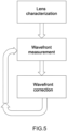
- the correction procedure which is not covered by the subject-matter of the claims, is shown in Figure 5 .
- the procedure involves the characterization of the wavefront deformation functions given by each individual actuator of the deformable lens. This is achieved by activating each actuator independently and by measuring the generated wavefront.
- the deformation functions generated also called influence functions in adaptive optics, are stored in a matrix called the matrix of influence functions "A". Within this matrix, each column contains the deformation of a single actuator. This information can also be obtained by activating multiple actuators simultaneously, by means of the technique called Hadamard matrix characterization.
- the characterization can be carried out on the microscope by means of the technique described above, i.e., by moving the variable iris or on a separate optical system equipped with a wavefront sensor (for example with a "Shack-Hartmann” sensor).
- the second operation is that of measuring the aberration of the system, which is carried out with the lens in a flat condition (all actuators off) or actuated on a previous position.
- This type of aberration correction can be used for the correction of any optical system.
- microscopes as explained above, of the image detection type with camera, and of the scanning type, such as, by way of non-limiting example, microscopes of the confocal, two-photon, optical coherence tomography, STED types and others. It can also be used for correcting aberrations in laser systems, without the use of wavefront sensors and by measuring aberrations in the experimental chamber.
- variable iris and the deformable lens can be conveniently placed outside the pupil of the optical system.
- they can be placed in an image plane of a plane on which system aberrations arise.
- the deformable lens and the variable iris can not be adjacent but placed on different positions in the optical system.
- they can be placed in mutual image planes.
- variable iris can be placed together with more than one deformable lens to increase the degree of correction.
- variable iris can also comprise one or more suitably shaped parts which, by means of the movement or rotation thereof, can create sub-pupils.
- they can be a pair of slits which rotate or translate independently, or one, two or more perforated discs which rotate and translate independently.
Landscapes
- Physics & Mathematics (AREA)
- General Physics & Mathematics (AREA)
- Optics & Photonics (AREA)
- Chemical & Material Sciences (AREA)
- Analytical Chemistry (AREA)
- Microscoopes, Condenser (AREA)
- Mechanical Light Control Or Optical Switches (AREA)
- Mounting And Adjusting Of Optical Elements (AREA)
- Testing Of Optical Devices Or Fibers (AREA)
- Lenses (AREA)
Claims (14)
- Optisches System, umfassend:- ein Objektiv (100),- einen Detektor (103), der geeignet ist, ein Bild einer Probe zu erfassen, wobei das Bild auf dem Detektor durch einen entlang eines optischen Weges von der Probe kommenden Lichtstrahl gebildet wird, und- eine Struktur (104) zum Messen und Korrigieren von Aberrationen des optischen Systems, wobei die genannte Struktur, im Inneren des optischen Weges, eine variable Blende (111) umfasst, wobei die variable Blende (111) geeignet ist, Unterpupillen (106, 113) zu bilden und jede Unterpupille (106, 113) ein Teil des Lichtstrahls ist und die variable Blende (111) geeignet ist, die Position einer Okklusion des Lichtstrahls zu ändern, die den Teil des Lichtstrahls zum Detektor (103) gelangen lässt,wobei die Struktur (104) darauf ausgelegt ist, die Messung einer Wellenfrontaberration auszuführen, indem sie eine Verschiebung des Bildes auf dem Detektor im Anschluss an eine Änderung der Position der Okklusion des Lichtstrahls misst,wobei die Struktur (104), im Inneren des optischen Weges, einen Wellenfrontmodulator umfasst;dadurch gekennzeichnet, dass der Wellenfrontmodulator eine verformbare Linse ist (105, 112, 123);wobei die Struktur darauf ausgelegt ist, die Aberration der Wellenfront zu korrigieren, indem sie den Wellenfrontmodulator abhängig von der Verschiebung des Bildes auf dem Detektor (103) betätigt; wobei das genannte Bild sich auf eine genannte Unterpupille (106, 113) bezieht;wobei der Wellenfrontmodulator und die variable Blende (111) aneinander angrenzen.
- Optisches System nach Anspruch 1, wobei die variable Blende (111) in dem optischen Pfad beweglich ist, um die Messung der Wellenfrontaberration durch Messen der Verschiebung eines Brennpunkts eines Lasers auf dem Detektor (103) in einer oder mehreren Positionen der variablen Blende (111) auszuführen.
- Optisches System nach Anspruch 1 oder 2, wobei die variable Blende (111) geeignet ist, die Form der Okklusion des Lichtstrahls zu ändern, die einen Teil des Lichtstrahls zum Detektor (103) gelangen lässt.
- Optisches System nach einem beliebigen der Ansprüche 1 bis 3, wobei die variable Blende (111) eine Lamellenstruktur ist.
- Optisches System nach einem beliebigen der Ansprüche 1 bis 3, wobei die variable Blende (111) eine gelochte Platte ist, die sich orthogonal zur optischen Achse bewegen kann.
- Optisches System nach einem beliebigen der Ansprüche 1 bis 3, wobei die variable Blende (111) ein rotierendes Blech (117) mit einer oder mehreren Öffnungen (119, 118) ist.
- Optisches System nach einem beliebigen der vorangegangenen Ansprüche, wobei die variable Blende (111) eine oder mehrere Nebenöffnungen (119) aufweist.
- Optisches System nach einem beliebigen der vorangegangenen Ansprüche, wobei die variable Blende (111) eine oder mehrere Nebenöffnungen (119) und eine Öffnung (118) in ausreichenden Größen aufweist, um die Pupille (107, 121) des optischen Systems nicht zu verdecken.
- Optisches System nach einem beliebigen der vorangegangenen Ansprüche, wobei der Wellenfrontmodulator und die variable Blende (111) einer rückseitigen Öffnung des Objektivs (100) gegenüberliegend angeordnet sind.
- Optisches System nach einem beliebigen der Ansprüche 1 bis 8, wobei der Wellenfrontmodulator und die variable Blende (111) im Inneren des Objektivs (100) gegenüberliegend angeordnet sind.
- Optisches System nach Anspruch 9 oder 10, wobei der Wellenfrontmodulator und die variable Blende (111) in der Pupille (107, 121) des optischen Systems positioniert sind.
- Optisches System nach Anspruch 9 oder 10, wobei der Wellenfrontmodulator und die variable Blende (111) in Bildebenen der Pupille (107, 121) des optischen Systems positioniert sind.
- Mikroskop, umfassend ein optisches System nach einem beliebigen der vorangegangenen Ansprüche.
- Laservorrichtung, umfassend ein optisches System nach einem beliebigen der Ansprüche 1-12.
Applications Claiming Priority (2)
| Application Number | Priority Date | Filing Date | Title |
|---|---|---|---|
| IT102019000019235A IT201900019235A1 (it) | 2019-10-21 | 2019-10-21 | Sistema integrato per la correzione delle aberrazioni ottiche |
| PCT/IB2020/059625 WO2021079232A1 (en) | 2019-10-21 | 2020-10-14 | Integrated system for the correction of optical aberrations |
Publications (3)
| Publication Number | Publication Date |
|---|---|
| EP4049080A1 EP4049080A1 (de) | 2022-08-31 |
| EP4049080B1 true EP4049080B1 (de) | 2024-12-18 |
| EP4049080C0 EP4049080C0 (de) | 2024-12-18 |
Family
ID=69903740
Family Applications (1)
| Application Number | Title | Priority Date | Filing Date |
|---|---|---|---|
| EP20800723.7A Active EP4049080B1 (de) | 2019-10-21 | 2020-10-14 | Optisches system |
Country Status (3)
| Country | Link |
|---|---|
| EP (1) | EP4049080B1 (de) |
| IT (1) | IT201900019235A1 (de) |
| WO (1) | WO2021079232A1 (de) |
Family Cites Families (4)
| Publication number | Priority date | Publication date | Assignee | Title |
|---|---|---|---|---|
| US8356900B2 (en) * | 2006-01-20 | 2013-01-22 | Clarity Medical Systems, Inc. | Large diopter range real time sequential wavefront sensor |
| WO2010073127A2 (en) | 2008-12-23 | 2010-07-01 | Varioptic S.A. | Optical electrowetting device |
| WO2011006106A1 (en) | 2009-07-09 | 2011-01-13 | Howard Hughes Medical Institute | Microscopy with adaptive optics |
| EP2860555A1 (de) | 2013-10-08 | 2015-04-15 | Optotune AG | Abstimmbare Linse |
-
2019
- 2019-10-21 IT IT102019000019235A patent/IT201900019235A1/it unknown
-
2020
- 2020-10-14 WO PCT/IB2020/059625 patent/WO2021079232A1/en not_active Ceased
- 2020-10-14 EP EP20800723.7A patent/EP4049080B1/de active Active
Also Published As
| Publication number | Publication date |
|---|---|
| WO2021079232A1 (en) | 2021-04-29 |
| EP4049080C0 (de) | 2024-12-18 |
| IT201900019235A1 (it) | 2021-04-21 |
| EP4049080A1 (de) | 2022-08-31 |
Similar Documents
| Publication | Publication Date | Title |
|---|---|---|
| EP2732326B1 (de) | Mikroskopie mit adaptiver optik | |
| CN106461925B (zh) | 用于具有自适应光学系统的拉曼散射光学显微镜的系统和方法 | |
| JP6360825B2 (ja) | 結像光学系、照明装置および観察装置 | |
| KR102128642B1 (ko) | 보상 광학 시스템의 조정 방법, 보상 광학 시스템, 및 보상 광학 시스템용 프로그램을 기억하는 기록 매체 | |
| JP5999121B2 (ja) | 共焦点光スキャナ | |
| JP5287252B2 (ja) | レーザ走査共焦点顕微鏡 | |
| US10558030B2 (en) | Structures illumination microscopy system, method, and non-transitory storage medium storing program | |
| JP6637976B2 (ja) | 歪曲収差の少ない顕微鏡 | |
| JP6071177B2 (ja) | 顕微鏡、画像取得装置及び画像取得システム | |
| CN111095073B (zh) | 在激光扫描显微镜中扫描激发辐射和/或操纵辐射的光学组件以及激光扫描显微镜 | |
| JP2008529082A (ja) | 補償走査光学顕微鏡 | |
| JP2018533769A (ja) | 広視野高分解能顕微鏡 | |
| JP7481351B2 (ja) | 波面解析装置、蛍光顕微鏡画像化システムおよび対象を顕微鏡画像化する方法 | |
| Booth et al. | Adaptive optics for microscopy | |
| CN115248498A (zh) | 基于led光源的结构光超分辨自适应显微镜装置及成像方法 | |
| EP3637167B1 (de) | Konfokale bereichsabtastrastermikroskopie (ascm) | |
| JP7094225B2 (ja) | 試料を検査する方法および顕微鏡 | |
| EP4049080B1 (de) | Optisches system | |
| JP2023109177A (ja) | 非対称psfを用いた顕微鏡における三次元画像化のための方法、装置及び顕微鏡 | |
| JP3455775B2 (ja) | 光駆動型波面補正映像方法及び装置 | |
| US11703672B2 (en) | Microscopic transmitted light contrasting method | |
| US6754000B2 (en) | Optical arrangement, and method for the deflection of light beams | |
| Geary | Wavefront sensors | |
| Haist et al. | Scene-based wavefront correction with spatial light modulators | |
| O'byrne et al. | Adaptive optics in confocal microscopy |
Legal Events
| Date | Code | Title | Description |
|---|---|---|---|
| STAA | Information on the status of an ep patent application or granted ep patent |
Free format text: STATUS: UNKNOWN |
|
| STAA | Information on the status of an ep patent application or granted ep patent |
Free format text: STATUS: THE INTERNATIONAL PUBLICATION HAS BEEN MADE |
|
| PUAI | Public reference made under article 153(3) epc to a published international application that has entered the european phase |
Free format text: ORIGINAL CODE: 0009012 |
|
| STAA | Information on the status of an ep patent application or granted ep patent |
Free format text: STATUS: REQUEST FOR EXAMINATION WAS MADE |
|
| 17P | Request for examination filed |
Effective date: 20220510 |
|
| AK | Designated contracting states |
Kind code of ref document: A1 Designated state(s): AL AT BE BG CH CY CZ DE DK EE ES FI FR GB GR HR HU IE IS IT LI LT LU LV MC MK MT NL NO PL PT RO RS SE SI SK SM TR |
|
| DAV | Request for validation of the european patent (deleted) | ||
| DAX | Request for extension of the european patent (deleted) | ||
| P01 | Opt-out of the competence of the unified patent court (upc) registered |
Effective date: 20230303 |
|
| GRAP | Despatch of communication of intention to grant a patent |
Free format text: ORIGINAL CODE: EPIDOSNIGR1 |
|
| STAA | Information on the status of an ep patent application or granted ep patent |
Free format text: STATUS: GRANT OF PATENT IS INTENDED |
|
| INTG | Intention to grant announced |
Effective date: 20240808 |
|
| GRAS | Grant fee paid |
Free format text: ORIGINAL CODE: EPIDOSNIGR3 |
|
| GRAA | (expected) grant |
Free format text: ORIGINAL CODE: 0009210 |
|
| STAA | Information on the status of an ep patent application or granted ep patent |
Free format text: STATUS: THE PATENT HAS BEEN GRANTED |
|
| AK | Designated contracting states |
Kind code of ref document: B1 Designated state(s): AL AT BE BG CH CY CZ DE DK EE ES FI FR GB GR HR HU IE IS IT LI LT LU LV MC MK MT NL NO PL PT RO RS SE SI SK SM TR |
|
| REG | Reference to a national code |
Ref country code: CH Ref legal event code: EP |
|
| REG | Reference to a national code |
Ref country code: DE Ref legal event code: R096 Ref document number: 602020043435 Country of ref document: DE |
|
| REG | Reference to a national code |
Ref country code: IE Ref legal event code: FG4D |
|
| U01 | Request for unitary effect filed |
Effective date: 20250114 |
|
| U07 | Unitary effect registered |
Designated state(s): AT BE BG DE DK EE FI FR IT LT LU LV MT NL PT RO SE SI Effective date: 20250120 |
|
| P04 | Withdrawal of opt-out of the competence of the unified patent court (upc) registered |
Free format text: CASE NUMBER: APP_2621/2025 Effective date: 20250116 |
|
| PG25 | Lapsed in a contracting state [announced via postgrant information from national office to epo] |
Ref country code: HR Free format text: LAPSE BECAUSE OF FAILURE TO SUBMIT A TRANSLATION OF THE DESCRIPTION OR TO PAY THE FEE WITHIN THE PRESCRIBED TIME-LIMIT Effective date: 20241218 |
|
| PG25 | Lapsed in a contracting state [announced via postgrant information from national office to epo] |
Ref country code: NO Free format text: LAPSE BECAUSE OF FAILURE TO SUBMIT A TRANSLATION OF THE DESCRIPTION OR TO PAY THE FEE WITHIN THE PRESCRIBED TIME-LIMIT Effective date: 20250318 |
|
| PG25 | Lapsed in a contracting state [announced via postgrant information from national office to epo] |
Ref country code: GR Free format text: LAPSE BECAUSE OF FAILURE TO SUBMIT A TRANSLATION OF THE DESCRIPTION OR TO PAY THE FEE WITHIN THE PRESCRIBED TIME-LIMIT Effective date: 20250319 |
|
| PG25 | Lapsed in a contracting state [announced via postgrant information from national office to epo] |
Ref country code: RS Free format text: LAPSE BECAUSE OF FAILURE TO SUBMIT A TRANSLATION OF THE DESCRIPTION OR TO PAY THE FEE WITHIN THE PRESCRIBED TIME-LIMIT Effective date: 20250318 |
|
| PG25 | Lapsed in a contracting state [announced via postgrant information from national office to epo] |
Ref country code: SM Free format text: LAPSE BECAUSE OF FAILURE TO SUBMIT A TRANSLATION OF THE DESCRIPTION OR TO PAY THE FEE WITHIN THE PRESCRIBED TIME-LIMIT Effective date: 20241218 |
|
| PG25 | Lapsed in a contracting state [announced via postgrant information from national office to epo] |
Ref country code: PL Free format text: LAPSE BECAUSE OF FAILURE TO SUBMIT A TRANSLATION OF THE DESCRIPTION OR TO PAY THE FEE WITHIN THE PRESCRIBED TIME-LIMIT Effective date: 20241218 |
|
| PG25 | Lapsed in a contracting state [announced via postgrant information from national office to epo] |
Ref country code: ES Free format text: LAPSE BECAUSE OF FAILURE TO SUBMIT A TRANSLATION OF THE DESCRIPTION OR TO PAY THE FEE WITHIN THE PRESCRIBED TIME-LIMIT Effective date: 20241218 |
|
| PG25 | Lapsed in a contracting state [announced via postgrant information from national office to epo] |
Ref country code: IS Free format text: LAPSE BECAUSE OF FAILURE TO SUBMIT A TRANSLATION OF THE DESCRIPTION OR TO PAY THE FEE WITHIN THE PRESCRIBED TIME-LIMIT Effective date: 20250418 |
|
| PG25 | Lapsed in a contracting state [announced via postgrant information from national office to epo] |
Ref country code: SK Free format text: LAPSE BECAUSE OF FAILURE TO SUBMIT A TRANSLATION OF THE DESCRIPTION OR TO PAY THE FEE WITHIN THE PRESCRIBED TIME-LIMIT Effective date: 20241218 |
|
| PG25 | Lapsed in a contracting state [announced via postgrant information from national office to epo] |
Ref country code: CZ Free format text: LAPSE BECAUSE OF FAILURE TO SUBMIT A TRANSLATION OF THE DESCRIPTION OR TO PAY THE FEE WITHIN THE PRESCRIBED TIME-LIMIT Effective date: 20241218 |
|
| PLBE | No opposition filed within time limit |
Free format text: ORIGINAL CODE: 0009261 |
|
| STAA | Information on the status of an ep patent application or granted ep patent |
Free format text: STATUS: NO OPPOSITION FILED WITHIN TIME LIMIT |
|
| U20 | Renewal fee for the european patent with unitary effect paid |
Year of fee payment: 6 Effective date: 20250926 |
|
| 26N | No opposition filed |
Effective date: 20250919 |