EP4048115B1 - Haarstylinggerät mit rotierendem schwenkzubehör - Google Patents
Haarstylinggerät mit rotierendem schwenkzubehör Download PDFInfo
- Publication number
- EP4048115B1 EP4048115B1 EP20792642.9A EP20792642A EP4048115B1 EP 4048115 B1 EP4048115 B1 EP 4048115B1 EP 20792642 A EP20792642 A EP 20792642A EP 4048115 B1 EP4048115 B1 EP 4048115B1
- Authority
- EP
- European Patent Office
- Prior art keywords
- accessory
- hair
- axis
- styling appliance
- appliance according
- Prior art date
- Legal status (The legal status is an assumption and is not a legal conclusion. Google has not performed a legal analysis and makes no representation as to the accuracy of the status listed.)
- Active
Links
Images


Classifications
-
- A—HUMAN NECESSITIES
- A45—HAND OR TRAVELLING ARTICLES
- A45D—HAIRDRESSING OR SHAVING EQUIPMENT; EQUIPMENT FOR COSMETICS OR COSMETIC TREATMENTS, e.g. FOR MANICURING OR PEDICURING
- A45D2/00—Hair-curling or hair-waving appliances ; Appliances for hair dressing treatment not otherwise provided for
- A45D2/12—Hair winders or hair curlers for use parallel to the scalp, i.e. flat-curlers
- A45D2/24—Hair winders or hair curlers for use parallel to the scalp, i.e. flat-curlers of multi-part type, e.g. with sliding parts other than for fastening
- A45D2/2464—Hair winders or hair curlers for use parallel to the scalp, i.e. flat-curlers of multi-part type, e.g. with sliding parts other than for fastening tube-like
- A45D2/2471—Hair winders or hair curlers for use parallel to the scalp, i.e. flat-curlers of multi-part type, e.g. with sliding parts other than for fastening tube-like comprising bristles
-
- A—HUMAN NECESSITIES
- A45—HAND OR TRAVELLING ARTICLES
- A45D—HAIRDRESSING OR SHAVING EQUIPMENT; EQUIPMENT FOR COSMETICS OR COSMETIC TREATMENTS, e.g. FOR MANICURING OR PEDICURING
- A45D2/00—Hair-curling or hair-waving appliances ; Appliances for hair dressing treatment not otherwise provided for
- A45D2/36—Hair curlers or hair winders with incorporated heating or drying means, e.g. electric, using chemical reaction
- A45D2/367—Hair curlers or hair winders with incorporated heating or drying means, e.g. electric, using chemical reaction with electrical heating means
-
- A—HUMAN NECESSITIES
- A45—HAND OR TRAVELLING ARTICLES
- A45D—HAIRDRESSING OR SHAVING EQUIPMENT; EQUIPMENT FOR COSMETICS OR COSMETIC TREATMENTS, e.g. FOR MANICURING OR PEDICURING
- A45D20/00—Hair drying devices; Accessories therefor
- A45D20/04—Hot-air producers
- A45D20/08—Hot-air producers heated electrically
- A45D20/10—Hand-held drying devices, e.g. air douches
- A45D20/12—Details thereof or accessories therefor, e.g. nozzles, stands
-
- A—HUMAN NECESSITIES
- A45—HAND OR TRAVELLING ARTICLES
- A45D—HAIRDRESSING OR SHAVING EQUIPMENT; EQUIPMENT FOR COSMETICS OR COSMETIC TREATMENTS, e.g. FOR MANICURING OR PEDICURING
- A45D20/00—Hair drying devices; Accessories therefor
- A45D20/48—Hair-drying combs or hair-drying brushes, with internal heating means
- A45D20/50—Hair-drying combs or hair-drying brushes, with internal heating means and provision for an air stream
-
- A—HUMAN NECESSITIES
- A45—HAND OR TRAVELLING ARTICLES
- A45D—HAIRDRESSING OR SHAVING EQUIPMENT; EQUIPMENT FOR COSMETICS OR COSMETIC TREATMENTS, e.g. FOR MANICURING OR PEDICURING
- A45D24/00—Hair combs for care of the hair; Accessories therefor
- A45D24/007—Hair combs for care of the hair; Accessories therefor power-driven
-
- A—HUMAN NECESSITIES
- A45—HAND OR TRAVELLING ARTICLES
- A45D—HAIRDRESSING OR SHAVING EQUIPMENT; EQUIPMENT FOR COSMETICS OR COSMETIC TREATMENTS, e.g. FOR MANICURING OR PEDICURING
- A45D6/00—Details of, or accessories for, hair-curling or hair-waving devices
- A45D6/04—Devices for winding the hair on flat-curlers
Definitions
- the present invention relates to the field of hairdressing devices and in particular to the field of hairdressing devices making it possible to create curls and/or waves on the hair.
- the present invention relates in particular to the field of hairdressing devices comprising a rotating accessory.
- the invention relates to the technical field of hairdressing appliances comprising a main body comprising a handle extending longitudinally along a first axis, an accessory intended to come into contact with the hair to shape the latter, said accessory extending longitudinally along a second axis, a motor for rotating the accessory around said second axis so that the hair can be wound around said accessory.
- This type of device gives excellent results in shaping hair and is therefore well appreciated by users.
- this type of device can sometimes present some difficulties when using it, particularly when the device is used by a single person who is looking to do their own hair.
- the document FR2978332 discloses a rotating blower brush.
- the present invention aims to overcome the aforementioned drawbacks.
- An objective of the invention is to provide a hairdressing device which is particularly ergonomic to use, whatever the area of the head to be styled.
- Another objective of the invention is to propose a hairdressing device which is particularly ergonomic to use, both for a user using the device on himself (user doing his own hair) and for a user using the device on another person (user styling another person), and this on all parts of the hair.
- Another objective of the invention is to propose a hairdressing device which is particularly comfortable to use.
- Another objective of the invention is to provide a hairdressing device which is particularly reliable and robust.
- Another objective of the invention is to propose a hairdressing device which is particularly economical to design and manufacture.
- Another objective of the invention is to provide a hairdressing device which is particularly easy to repair.
- Another objective of the invention is to provide a hairdressing device which is particularly effective for shaping hair, in particular for creating curls or waves or obtaining a "brushing" effect on these. last.
- handle we mean for example any element allowing a user to grasp and manipulate the hairdressing appliance, such as a handle for example.
- the handle can advantageously form the main body or, on the contrary, be separated from the main body, while still being connected to the latter.
- the handle is aligned with the main body.
- the handle and the main body both extend along the first axis.
- the hairdressing device is thus advantageously portable, that is to say it can be transported and oriented in space according to the user's wishes.
- the accessory has a revolution shape, and advantageously a cylindrical shape, which maximizes the surface area coming into contact with the hair to shape it.
- a shape makes it easier to rotate the accessory.
- the accessory is removable, that is to say removable, that is to say that it is possible for the user to remove the accessory from the hairdressing appliance, that is i.e. to separate the accessory and the handle, for example to replace it with another accessory of a different size and/or shape.
- This allows the user to choose as they wish the hairstyle that they will create on their hair, in particular by being able to choose the diameter of the curls or waves that they will create using the accessory.
- This can also allow the user to choose the most suitable accessory depending on the nature of their hair.
- the accessory comprises a contact surface intended to serve as a hair winding surface and a plurality of pins projecting from said contact surface. Said plurality of pins makes it possible to grip the hair and, combined with the rotation of the accessory, to wrap it well around the winding surface.
- the contact surface is a surface of revolution, advantageously cylindrical thus forming a mandrel on which the hair can wind automatically under the effect of the rotation of the accessory.
- the motor is an electric motor.
- the expression "motor” could designate a motor driven by another energy, such as for example pneumatic, magnetic or even human energy.
- each of said first position and second position guarantees the correct extraction of air through the air outlet.
- the accessory in two distinct and different positions.
- said first axis and second axis form a flat angle: they are therefore either aligned (that is to say merged) or parallel.
- the accessory and the handle are either aligned (one being an extension of the other), (that is to say merged) or parallel.
- said first axis and second axis form an angle which is not flat: they are therefore neither aligned, nor merged, nor parallel.
- the accessory and the handle form an elbow, one being inclined relative to the other.
- the positions retained are either a position in which the accessory is aligned with the main body, or a position in which the accessory is inclined relative to the main body.
- the hairdressing device which is the subject of the invention in the first position to shape his hair located on the side of his head, in a manner known as such.
- the ergonomics of the hairdressing device as defined by the invention is also optimized for a user who would use the hairdressing device on a third person, for example for a hairdresser who would perform a hairstyle on a client.
- the user can place the accessory in the second position to easily reach the hair located on the top of the head of the person to be styled, while keeping their arm alongside the body, a position which is particularly ergonomic.
- the accessory is movable between exactly the first position and the second position, that is to say that the accessory has only two possible positions each allowing the rotation of the accessory. In other words, there is no intermediate position allowing the device to function properly between the first position and the second position.
- said first position and second position are stable positions and defined by design.
- the first position and the second position are pre-existing positions, defined by the designers of the device, in which the accessory is automatically maintained. This ensures that the user can only select the best positions of the device, those which guarantee the best ergonomics, positions which will have been carefully defined in advance by the designers of the device. This is particularly suitable for people new to hairdressing operations.
- the user cannot define said first position and second position, he can simply move the accessory between one and the other, the accessory being automatically maintained either in the first position or in the second position . This is particularly interesting for a user who does not have particular knowledge of ergonomics or hairstyles, thus limiting the risk of error for the user.
- the stability of the accessory alternately in one or the other of said first and second positions ensures the proper maintenance of the accessory in the position chosen by the user (in this case the first or the second) , regardless of the effort applied to the accessory. This therefore avoids any accidental or unwanted movement of the accessory, particularly during hair styling operations where significant forces can be exerted on the accessory, efforts which tend to cause the accessory to move and therefore cause it to leave its position. position.
- the second axis forms an angle ⁇ different from the right angle with the first axis when the accessory is in the second position.
- said angle ⁇ is between 100° and 170°, preferably between 130° and 170° and advantageously equal to 150°.
- the designers of the device noticed that these angle ranges were particularly advantageous for optimizing the ergonomics of the hairdressing device, whether for a user using the device on himself or for a user using the device on a third person, as explained previously.
- the main body comprises a joint located between and connecting the handle and the accessory.
- a joint placed between the handle and the accessory allows the user to move the accessory between the first position and the second position as desired and with complete ease.
- the articulation then comprises a first inclined side and a second inclined side, said first inclined side and second inclined side being movable relative to each other so as to move the accessory between said first positions and second position.
- Such a blocking device makes it possible to ensure the automatic maintenance of the accessory in one or other of said first or second positions (that is to say alternately in one and the other of said first and second position) according to the user's wishes, in a safe, reliable and inexpensive manner.
- said free position is preferably an unstable position while said locked position is a stable position. This therefore encourages the user to systematically place the accessory either in the first position or in the second position, strongly dissuading him (not to say forbidding him) from placing the accessory in another position since the blocking device will then refuse to lock.
- This allows the novice user to easily select the best positions for using the the device.
- This also guarantees that the accessory is maintained either in the first position or in the second position and avoids any unwanted evolution of the accessory: in fact, positive action by the user is necessary on the blocking device to be able to move the accessory from one position to another.
- the rotation drive motor of the accessory is located inside said accessory.
- This embodiment is particularly well suited to the advantageous case where the accessory is hollow. This makes it possible to arrange the rotational drive motor of the accessory outside the main body, and in particular outside the handle, and therefore to reduce the size of the latter, in particular its diameter which further improves the ergonomics of the device.
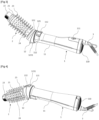
- the hairdressing appliance which is the subject of the invention is a blower brush, that is to say, a device combining the functions of drying and brushing hair. More precisely, the device illustrated is a rotating blower brush, that is to say that the device, in addition to being able to blow hot air, has a rotating accessory allowing you to create curls or waves in the hair, as will be detailed later.
- the main body 1 also includes an air inlet 110 located at the free end of the main body 1 as can be seen in the figures.
- an air inlet is typically used on “blowing brush” type hairdressing appliances. It is therefore through this air inlet 110 that the air is sucked in by the air moving device, heated by the air heating device, then then extracted from the main body 1 by the end connected to an accessory 2, as will be detailed later.
- the air inlet 110 typically comprises a grid, advantageously removable, intended to prevent foreign bodies (such as hair for example) from being sucked in by the air movement device.
- the main body 1 can be formed of two half-shells assembled together so as to facilitate assembly, disassembly, repair or maintenance operations of the device.
- the main body 1 extends longitudinally along a first axis PP' as illustrated by the figures 6 and 7 . As we can see, the main body extends between a free end (that is to say which is not connected to other parts) and an end intended to receive an accessory, as will be detailed by the following. More precisely, the main body 1 has a shape of revolution around the first axis P-P', in particular a cylindrical shape. This makes it possible to combine the ergonomic and reception functions of the different components, as explained previously.
- the main body 1 comprises a handle 11 intended to be grasped by the user. Thus, it is through this handle 11 that the user can easily grasp the main body 1 and manipulate the hairdressing appliance.
- the handle 11 is part of the main body 1 and is formed by a zone of reduced diameter of the main body 1 in order to facilitate its grip by the user's hand.
- the handle 11 and the main body 1 both extend along the first axis P-P', preferably being coaxial.
- the main body 1 comprises a first control device 111 designed to control the air moving device and the air heating device. More precisely, the first control device 111 is a sliding button with several positions, four in this case: an off position, a cold air blowing position (that is to say that the heating device of the air is not activated, only the air movement device being activated), a position corresponding to an intermediate level of heating and air flow (i.e. the heating device and the air moving device are not at full power) and a position corresponding to a maximum level of heating and air flow (i.e. the heating device and the device air movement are at full power).
- an off position that is to say that the heating device of the air is not activated, only the air movement device being activated
- a position corresponding to an intermediate level of heating and air flow i.e. the heating device and the air moving device are not at full power
- a position corresponding to a maximum level of heating and air flow i.e. the heating device and the device air movement are at full power.
- the main body 1 is connected to a power cord 3 so as to provide adequate energy to the various components of the hairdressing appliance, in particular the device for moving the air or the air heating device.
- the power cord 3 is in this case an electrical cord making it possible to supply the components with electrical energy but one could imagine other types of power cords, such as for example a pneumatic cord for supplying air to pneumatic components .
- the hairdressing appliance is powered by an internal source (a battery for example), so that it would then have no power cord 3.
- the hairdressing device also includes an accessory 2 intended to come into contact with the hair to shape it.
- the accessory is removable, as can be seen in the Figure 7 .
- the accessory 2 comprises a contact surface 21 intended to serve as a hair winding surface. More precisely, the contact surface 21 is a surface of revolution, and in particular a cylindrical surface so as to optimize the winding of the hair on the latter. Such a contact surface 21 makes it possible to create curls or waves or even a “brushing” effect on the hair.
- the contact surface 21 is made of a material which is a good thermal conductor (such as steel or aluminum for example) in order to diffuse the heat from the air towards the hair. This helps to secure the styling of the hair.
- the accessory 2 extends longitudinally along a second axis A-A', as can be seen on the figures 6 and 7 . More precisely, the accessory 2 has a form of revolution around the second axis A-A'. Accessory 2 is hollow.
- the accessory 2 also includes an air outlet 24.
- the air outlet 24 then comprises a plurality of holes as can be seen on the figures 1 to 6 . Said plurality of holes is then regularly distributed over the contact surface 21, in particular by being arranged in the form of rows between the pins 23. This makes it possible to properly diffuse the air extracted from the hairdressing appliance inside the hair, gently and evenly.
- the diameter of each of the holes of the air outlet 24 decreases according to the direction of the air flow, that is to say decreasing from the main body 1 towards the free end of the accessory 2. This contributes to maintain a relatively constant flow of air emitted despite the increasing distance from the air inlet 110.
- the accessory 2 includes a gripping tip 22 intended to be grasped by the user when using the hairdressing appliance.
- Said gripping tip 22 is made of insulating material so as not to transmit the heat from the accessory 2 to the user's fingers.
- the gripping tip 22 can be mounted to rotate freely relative to the accessory 2 in order to remain stationary in the user's fingers despite the rotation of the accessory 2. This makes it possible to improve the comfort of use of the the device but also the precision of the styling operation.
- the gripping end 22 also allows the assembly and disassembly operations of the accessory, as is known as such.
- the hairdressing appliance also comprises a motor for driving the accessory 2 in rotation around said second axis A-A' so that the hair can be wound around said accessory 2. More precisely the motor is an electric motor, as is clearly known as such.
- the motor for driving the accessory 2 in rotation is located inside said accessory 2.
- the motor for rotating the accessory 2 is offset from the main body 1: the motor for driving it in rotation rotation the accessory 2 is located outside the main body 1.
- the hairdressing appliance comprises a first motor inside the main body 1 (the drive motor of the air moving device) and a motor inside of accessory 2 (the rotation drive motor of the latter). The ergonomics and comfort of use of the hairdressing device are therefore improved.
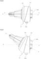
- the hairdressing appliance comprises an accessory support 4 which itself includes the motor to rotate the accessory 2.
- the accessory 2 is therefore arranged around the accessory support 4.
- the accessory support 4 includes a proximal part 41 connected to the main body 1.
- the proximal part 41 comprises an air guiding device 411.
- the air guiding device 411 may in particular comprise fins, as illustrated, which then contribute to straightening the air flow coming from the placing device. Movement of the air, so as to create a laminar air flow.
- the air guiding device 411 may include arches.
- the accessory support 4 comprises a distal part 42 located opposite the proximal part 41.
- the distal part 42 is a free part, that is to say it is not connected to the main body 1 as can be seen on the figures 7 Or 10 .
- the distal part 42 comprises a rotation drive device 421 of the accessory 2. More precisely, the rotation drive device 421 of the accessory 2 comprises grooves intended to correspond with a complementary receiving device located at inside the accessory 2, as is known to those skilled in the art.
- the distal part 42 also comprises an assembly and holding device 422 for the accessory 2 which itself comprises by example a groove. The groove is then intended to correspond with a complementary assembly and holding device located inside the accessory 2 as is known to those skilled in the art.
- the assembly and holding device 422 and the complementary assembly and holding device of the accessory also allow the user to disassemble the accessory, as is known as such.
- the rotation drive motor of the accessory 2 is mounted inside the accessory support 4, the output shaft of said motor is connected to the rotation drive device 421 of the distal part 42 of the accessory support 4, said rotation drive device 421 itself being connected to the accessory 2 so as to transmit the rotational movement of said motor to the accessory 2.
- the proximal part 41 is also connected to the motor d rotational drive of the accessory 2 to the extent that the latter generally houses the electrical cables powering said motor.
- the main body 1 also includes a joint 12.
- the joint 12 is then located between the handle 11 and the accessory 2. More precisely the joint 12 is connected to the accessory support 4 and is arranged at one end of the main body 1.
- the articulation 12 also makes it possible to connect the handle 11 and the accessory 2, or more precisely the accessory support 4.
- articulation we mean any device allowing at least an angular movement between two parts connected to each other by said articulation 12, in this case, between the handle 11 and the accessory support 4, and therefore finally the accessory 2.
- the figures 8 to 11 illustrate in detail an example of a joint used in the hairdressing device of the preceding figures.
- the articulation 12 comprises a first inclined section 121, that is to say a first part, one face of which is inclined relative to the first axis P-P'.
- the articulation 12 also includes a second inclined section 122, that is to say a second part, one face of which is inclined relative to the second axis A-A'.
- Said first inclined face 121 and second inclined face 122 are parts of revolution, in particular cylinder portions, beveled cylinders, as illustrated.
- the first inclined section 121 extends longitudinally along the first axis P-P' and around the first axis P-P'.
- the second inclined section 122 extends longitudinally along the second axis A-A' and around the second axis A-A'.
- the first inclined part 121 is connected to the handle 11, as can be seen on the figures 6 and 7 , while the second inclined panel 122 is connected to the accessory support 4, more precisely to the proximal part 41 of the latter.
- the second inclined section 122 is connected (indirectly) to the accessory 2.
- first and second inclined sections 121, 122 are movable relative to each other, more particularly in a plane support movement, as illustrated by the figures 8, 9 And 11 .
- the first inclined face 121 comprises a first plane 1211
- the second inclined face 122 comprises a second plane 1221.
- said second inclined face 122 in motion relative to the first inclined face 121 (or vice versa)
- the second plane 1221 will move on the first plane 1211 (or vice versa).
- said first plane 1211 and second plane 1221 form disk portions.
- first inclined side 121 and second inclined side 122 are hooked to one another in order to maintain the joint 12 in the form of a unitary part.
- first inclined face 121 comprises a guiding and hooking device 1212 while the second inclined face 122 comprises a complementary guiding and hooking device 1222.
- the guiding and hooking device 1212 comprises a plurality of tongues projecting from the first plane 1211 towards the second plane 1221 of the second inclined surface 122.
- the complementary guiding and hooking device 1222 comprises a groove, or a groove, made on the second plane 1221, inside the second inclined face 122.
- said groove, or groove receives said plurality of tongues.
- Each of the tabs has a hook at its free end so as to remain engaged in the groove or groove, as can be seen on the Figure 11 .
- the guiding and hooking device 1212 is designed to penetrate at least partially inside the complementary guiding and hooking device 1222, which makes it possible to ensure the assembly between the first inclined side 121 and the second side inclined 122.
- the complementary guiding and hooking device 1222 is designed to receive the guiding and hooking device 1212 so as to ensure blocking in translation but a degree of freedom in rotation.
- the plurality of tongues of the guide and hooking device 1212 can slide inside the groove of the complementary guide and hooking device 1222, without however being able to be extracted therefrom, thanks to the hooks.
- the joint 12 can take at least two positions: a first position illustrated in figure 8 and a second position illustrated in Figure 9 .
- first position of the articulation 12 of the figure 8 corresponds to the first position of accessory 2 of the figure 1 or 2
- second position of the articulation 12 of the Figure 9 corresponds to the second position of the accessory of the figure 3 or 4 .
- the entire articulation 12 is oriented along the first axis P-P', that is to say that the first inclined face 121 and the second inclined face 122 are both aligned on the first axis P-P'.
- the first inclined face 121 and the second inclined face 122 extend longitudinally along and around the first axis P-P'.
- the first plane 1211 and second plane 1221 are arranged in a staggered or “head-to-tail” pattern.
- the joint 12 being connected on the one hand to the accessory 2 and on the other hand to the handle 11, the joint 12 allows the accessory 2 to be movable between the first position and the second position, that is to say, allows the accessory 2 to be oriented either along the first axis P-P', or along the second axis A-A', as can be seen on the figures 6 and 7 notably.
- the accessory 2 can therefore, depending on the wishes of the user who will handle the device, be either in the axis of the handle 11 or bent relative to the handle 11.
- the joint 12 further comprises a locking device 123.
- the latter is then designed to block the joint 12 in the first position or in the second position, that is to say to hold the joint 12 in the one or the other of the positions, avoiding any untimely movement of the joint 12.
- the blocking device 123 is movable between two positions: a free position, allowing the accessory 2 to move between said at least first position and second position, and a locked position blocking said accessory 2 in one of said first position or second position.
- FIG. 11 illustrates in detail this blocking device 123.
- the latter thus comprises a third control device 1231, in this case a push button, intended to be manipulated by the user of the hairdressing appliance.
- the third control device 1231 projects radially from the first inclined side 121, so that it can easily be operated by the thumb or index finger of the user's hand which holds the hairdressing appliance by the handle 11 as can be understand it about figures 1 to 4 .
- the blocking device 123 also includes a lug 1232 connected to the third control device 1231.
- the lug 1232 projects longitudinally from the first plane 1211 of the first inclined surface 121, in the same direction as the guiding and hooking device 1212.
- the lug 1232 is therefore arranged perpendicular to the third control device 1231.
- the lug 1232 is driven by a translational movement, vertical with reference to the figures, when the third control device 1231, in this case the push button, is activated by the user.
- the blocking device 123 also includes a first notch 1233 and a second notch 1234 each made in the second inclined face 122. Said first notch 1233 and second notch 1234 are diametrically opposed as can be seen in the Figure 11 . Each of said first notch 1233 and second notch 1234 is then designed to alternately receive the lug 1232.
- the lug 1232 will then prevent the relative rotation between the first inclined face 121 and second inclined face 122, thus ensuring that the joint 12 is maintained in position, whatever the force exerted on the accessory.
- the joint 12 is blocked in the first position, that is to say that the entire joint 12 is oriented along the first axis P-P', that is to say that the accessory 2 and the main body 1 are aligned along the first axis P-P'.
- Said first inclined side 121 and second inclined side 122 are then arranged staggered or “head to tail” as explained previously.
- the blocking device 123 also includes an elastic return device, a spring for example (not illustrated), in the locked position.
- the free position is an unstable position while the locked position is a stable position.
- the joint 12 is blocked, which prevents any unwanted movement of the latter, and therefore any unwanted movement of the accessory 2 relative to the main body 1.
- the elastic return device ensures automatic blocking of the joint 12 in one or other of the first or second positions as soon as the lug 1232 arrives opposite one or the other of the first notch 1233 or second notch 1234, that is to say as soon as the articulation 12 arrives in one or the other of the first or second position, that is to say as soon as the accessory 2 arrives in the 'either of the first or second position.
- This makes using joint 12 more intuitive.
- the joint 12 comprises an air channel 124 designed to allow the air flow to pass from the air inlet 110 to the air outlet 24, the air being set in motion by the setting device. air movement, as explained previously.
- the air channel 124 comprises a tube 1241 which delimits said first planes 1211 and second plane 1221.
- the air channel 124 comprises a plurality of walls 1242, arranged radially inside the tube 1241. Said plurality of walls 1242 thus forms different channels which make it possible to properly direct the air flow, in particular in a longitudinal direction.
- the walls 1242 make it possible in particular to reduce, or even eliminate, the rotating or swirling component of the air flow leaving the air movement device.
- the accessory support 4 is oriented along the second axis A-A', that is to say it forms an angle with respect to the main body 1.
- each of the first and second positions allows the rotation of the accessory 2 by the motor driving the rotation of the accessory arranged at the inside the accessory holder 4.
- the joint 12 is designed to be movable between exactly two positions: the first position or the second position. Consequently, the accessory 2 is movable between exactly the first position and the second position.
- the accessory 2 is designed to operate normally, that is to say be able to be rotated by the accessory drive motor, only in these two positions. This makes it possible to limit the number of scenarios for using the hairdressing device, which simplifies the use of the device for the user while providing an ergonomic device. This also limits the costs of designing and manufacturing the hairdressing device.
- accessory 2 could evolve between three, four, five or a plurality of different positions, each of them allowing the rotation of the accessory 2 around the second axis A-A'.
- accessory 2 could move between, not different predefined positions, but an infinity of positions, that is to say that accessory 2 could operate in any position. This will for example be possible with a flexible joint, including for example a cardan joint.
Landscapes
- Cleaning And Drying Hair (AREA)
- Brushes (AREA)
- Dry Shavers And Clippers (AREA)
Claims (15)
- Frisiereinrichtung, umfassend:- einen Hauptkörper (1), der einen Griff (11) umfasst, der sich längslaufend entlang einer ersten Achse (P-P') erstreckt,- ein Zubehör (2), das dazu vorgesehen ist, mit Haaren in Kontakt zu kommen, um diese Letztere in Form zu bringen, wobei sich das Zubehör (2) längslaufend entlang einer zweiten Achse (A-A') erstreckt,- einen Motor zum drehenden Antrieb des Zubehörs (2) um die zweite Achse (A-A') herum, damit die Haare um das Zubehör (2) herum aufgewickelt werden können,dadurch gekennzeichnet, dass das Zubehör (2) zwischen mindestens zwei Positionen beweglich ist, die jeweils die Drehung des Zubehörs (2) um die zweite Achse (A-A') herum erlauben:- einer ersten Position, bei der die zweite Achse (A-A') und die erste Achse (P-P') untereinander einen flachen Winkel bilden,- einer zweiten Position, bei der die zweite Achse (A-A') und die erste Achse (P-P') untereinander einen von dem flachen Winkel unterschiedlichen Winkel bilden.
- Frisiereinrichtung nach dem vorstehenden Anspruch, wobei das Zubehör (2) zwischen genau der ersten Position und der zweiten Position beweglich ist.
- Frisiereinrichtung nach einer der vorstehenden Ansprüche, wobei die erste Position und die zweite Position stabile Positionen sind und per Design definiert sind.
- Frisiereinrichtung nach einer der vorstehenden Ansprüche, wobei die zweite Achse (A-A') mit der ersten Achse (P-P') einen von dem rechten Winkel unterschiedlichen Winkel α bildet, wenn das Zubehör (2) in der zweiten Position ist.
- Frisiereinrichtung nach dem vorstehenden Anspruch, wobei der Winkel α zwischen 100° und 170°, vorzugsweise zwischen 130° und 170° beträgt und vorteilhafterweise gleich 150° ist.
- Frisiereinrichtung nach einer der vorstehenden Ansprüche, wobei der Hauptkörper (1) ein Gelenk (12) umfasst, das sich zwischen dem Griff (11) und dem Zubehör (2) befindet und diese verbindet.
- Frisiereinrichtung nach dem vorstehenden Anspruch, wobei das Gelenk (12) eine erste schräge Seite (121) und eine zweite schräge Seite (122) umfasst, wobei die erste schräge Seite (121) und die zweite schräge Seite (122) in Bezug zueinander derart beweglich sind, dass sie das Zubehör (2) zwischen der ersten Position und der zweiten Position übergehen lassen.
- Frisiereinrichtung nach dem Anspruch 6 oder 7 und dem Anspruch 3, wobei das Gelenk (12) eine Arretierungsvorrichtung (123) umfasst, die beweglich ist zwischen einer freien Position, die dem Zubehör (2) erlaubt, zwischen der ersten Position und der zweiten Position überzugehen, und einer verriegelten Position, die das Zubehör (2) in einer von der ersten Position oder der zweiten Position arretiert.
- Frisiereinrichtung nach dem vorstehenden Anspruch, wobei die freie Position eine instabile Position ist, wohingegen die verriegelte Position eine stabile Position ist.
- Frisiereinrichtung nach einem der vorstehenden Ansprüche, wobei sich der Motor zum drehenden Antrieb des Zubehörs (2) im Inneren des Zubehörs (2) befindet.
- Frisiereinrichtung nach einem der vorstehenden Ansprüche, wobei die Frisiereinrichtung eine Vorrichtung zur Versetzung der Luft zwischen einem Lufteingang (110) und einem Luftausgang (24) in Bewegung umfasst.
- Frisiereinrichtung nach dem vorstehenden Anspruch, wobei der Hauptkörper (1) den Lufteingang (110) umfasst und das Zubehör (2) den Luftausgang (24) umfasst.
- Frisiereinrichtung nach dem vorstehenden Anspruch, wobei der Luftausgang (24) eine Vielzahl von Öffnungen umfasst.
- Frisiereinrichtung nach einem der Ansprüche 11 bis 13, wobei die Frisiereinrichtung eine Lufterwärmungsvorrichtung umfasst.
- Frisiereinrichtung nach einem der vorstehenden Ansprüche, wobei das Zubehör (2) eine Kontaktfläche (21), die dazu vorgesehen ist, als Wickelfläche der Haare zu dienen, und eine Vielzahl von Zacken (23), die von der Kontaktfläche (21) hervorstehen, umfasst.
Applications Claiming Priority (2)
| Application Number | Priority Date | Filing Date | Title |
|---|---|---|---|
| FR1911964A FR3102347B1 (fr) | 2019-10-25 | 2019-10-25 | appareil de coiffure avec accessoire rotatif orientable |
| PCT/EP2020/079136 WO2021078633A1 (fr) | 2019-10-25 | 2020-10-15 | Appareil de coiffure avec accessoire rotatif orientable |
Publications (2)
| Publication Number | Publication Date |
|---|---|
| EP4048115A1 EP4048115A1 (de) | 2022-08-31 |
| EP4048115B1 true EP4048115B1 (de) | 2023-11-15 |
Family
ID=69375535
Family Applications (1)
| Application Number | Title | Priority Date | Filing Date |
|---|---|---|---|
| EP20792642.9A Active EP4048115B1 (de) | 2019-10-25 | 2020-10-15 | Haarstylinggerät mit rotierendem schwenkzubehör |
Country Status (6)
| Country | Link |
|---|---|
| EP (1) | EP4048115B1 (de) |
| CN (1) | CN114599251B (de) |
| ES (1) | ES2971431T3 (de) |
| FR (1) | FR3102347B1 (de) |
| PL (1) | PL4048115T3 (de) |
| WO (1) | WO2021078633A1 (de) |
Families Citing this family (14)
| Publication number | Priority date | Publication date | Assignee | Title |
|---|---|---|---|---|
| FR3091154B1 (fr) * | 2018-12-28 | 2021-10-22 | Seb Sa | appareil de coiffure avec embout de préhension pour le refroidissement du moteur |
| CN218791006U (zh) * | 2021-11-12 | 2023-04-07 | 尚科宁家运营有限公司 | 毛发护理器具 |
| US12225995B2 (en) | 2021-11-12 | 2025-02-18 | Sharkninja Operating Llc | Hair care appliance |
| US11653737B1 (en) | 2021-11-12 | 2023-05-23 | Sharkninja Operating Llc | Hair care appliance |
| CN118716755A (zh) * | 2021-11-12 | 2024-10-01 | 尚科宁家运营有限公司 | 护发用具 |
| US12501982B2 (en) | 2021-11-12 | 2025-12-23 | Sharkninja Operating Llc | Hair care appliance |
| USD1021238S1 (en) | 2022-06-02 | 2024-04-02 | Sharkninja Operating Llc | Hair care appliance |
| CN115088930B (zh) * | 2022-07-18 | 2024-03-22 | 杭州乐秀电子科技有限公司 | 柱状吹风机 |
| FR3140742A1 (fr) | 2022-10-14 | 2024-04-19 | Seb S.A. | Appareil de coiffure à tête rotative et à sélection automatique du sens de rotation de ladite tête |
| US20250213029A1 (en) | 2023-01-19 | 2025-07-03 | Sharkninja Operating Llc | Hair care appliance with powered attachment |
| US20240245190A1 (en) | 2023-01-19 | 2024-07-25 | Sharkninja Operating Llc | Identification of hair care appliance attachments |
| GB2633040A (en) * | 2023-08-30 | 2025-03-05 | Dyson Technology Ltd | Haircare appliance |
| CN221228883U (zh) * | 2023-11-23 | 2024-06-28 | 深圳市奋达科技股份有限公司 | 一种易于操作卷发器 |
| FR3157082B1 (fr) | 2023-12-21 | 2026-01-02 | Seb Sa | Appareil de coiffure à tête rotative, à sélection automatique du sens de rotation de la tête et assistance au démêlage |
Citations (1)
| Publication number | Priority date | Publication date | Assignee | Title |
|---|---|---|---|---|
| EP2131695B1 (de) * | 2007-04-06 | 2014-05-07 | Seb S.A. | Elektrische haarbürste |
Family Cites Families (6)
| Publication number | Priority date | Publication date | Assignee | Title |
|---|---|---|---|---|
| JPH0513281Y2 (de) * | 1988-01-18 | 1993-04-08 | ||
| FR2978332B1 (fr) * | 2011-07-27 | 2015-08-14 | Seb Sa | Brosse a cheveux electrique avec accessoire evolutif |
| FR2978333B1 (fr) * | 2011-07-27 | 2014-08-22 | Seb Sa | Brosse a cheveux electrique avec accessoire non cylindrique |
| FR3031018B1 (fr) * | 2014-12-30 | 2017-02-10 | Seb Sa | Appareil de coiffure multifonction de type brosse tournante |
| US20160302547A1 (en) * | 2015-04-14 | 2016-10-20 | Todd Jones | Multi-Angle Adjustable Curling Iron |
| US20180360185A1 (en) * | 2017-06-16 | 2018-12-20 | John Paul Mitchell Systems | Curling iron with adjustable heating rod |
-
2019
- 2019-10-25 FR FR1911964A patent/FR3102347B1/fr active Active
-
2020
- 2020-10-15 PL PL20792642.9T patent/PL4048115T3/pl unknown
- 2020-10-15 EP EP20792642.9A patent/EP4048115B1/de active Active
- 2020-10-15 WO PCT/EP2020/079136 patent/WO2021078633A1/fr not_active Ceased
- 2020-10-15 ES ES20792642T patent/ES2971431T3/es active Active
- 2020-10-15 CN CN202080074322.4A patent/CN114599251B/zh active Active
Patent Citations (1)
| Publication number | Priority date | Publication date | Assignee | Title |
|---|---|---|---|---|
| EP2131695B1 (de) * | 2007-04-06 | 2014-05-07 | Seb S.A. | Elektrische haarbürste |
Also Published As
| Publication number | Publication date |
|---|---|
| PL4048115T3 (pl) | 2024-05-13 |
| CN114599251A (zh) | 2022-06-07 |
| WO2021078633A1 (fr) | 2021-04-29 |
| FR3102347A1 (fr) | 2021-04-30 |
| ES2971431T3 (es) | 2024-06-05 |
| EP4048115A1 (de) | 2022-08-31 |
| CN114599251B (zh) | 2024-11-01 |
| FR3102347B1 (fr) | 2021-10-22 |
Similar Documents
| Publication | Publication Date | Title |
|---|---|---|
| EP4048115B1 (de) | Haarstylinggerät mit rotierendem schwenkzubehör | |
| EP3902440B1 (de) | Frisiervorrichtung mit drehbarer kopfkomponente | |
| EP2736374B1 (de) | Elektrische haarbürste mit einstellbarem zubehör | |
| EP3220769B1 (de) | Frisiergerät mit wärmeisolationsmittel | |
| FR3104916A1 (fr) | Appareil de coiffure multifonction a accessoire rotatif verrouillable en position par rapport au manche | |
| EP4355166A1 (de) | Frisiervorrichtung mit mehreren blasmodi mit einem push-push-steuermechanismus | |
| WO2013041805A1 (fr) | Accessoire de coiffure pour seche-cheveux | |
| EP3240455A1 (de) | Verbessertes zubehör für eine elektrische haarbürste | |
| EP4048116B1 (de) | Haarformgerät, das ein schwenkbares gebläsezubehör umfasst | |
| EP3845091B1 (de) | Verbessertes frisiergerät, das eine schwingende fönbürste bildet | |
| EP1124466A1 (de) | Zubehör zum glätten von haaren | |
| EP4355167B1 (de) | Haarstylinggerät mit verbessertem oszillierendem gebläse-bürsten-modus | |
| EP4079185B1 (de) | Frisiergerät mit verstellbarem zubehörteil und vorrichtung zur verriegelung des zubehörteils | |
| CH661643A5 (fr) | Ensemble d'accessoires pour la coupe, le sechage et la mise en forme d'une coiffure. | |
| EP4609750A1 (de) | Frisiergerät mit einem blaskopf mit versetzten luftleitblechen | |
| EP4385356B1 (de) | Multimodale blashaarformungsvorrichtung mit einem blaskopf mit selektiv ausgerichteten internen luftleitblechen | |
| RU2811970C1 (ru) | Парикмахерское устройство с ориентируемым вращающимся приспособлением | |
| FR3161533A1 (fr) | Appareil de coiffure multifonction à soufflage d’air radial | |
| RU2814087C1 (ru) | Парикмахерское устройство с ориентируемым воздуходувным приспособлением | |
| EP4601502A1 (de) | Frisiervorrichtung mit einem drehkopf und automatischer auswahl der drehrichtung des kopfes | |
| WO2025133523A1 (fr) | Appareil de coiffure a tete rotative, a selection automatique du sens de rotation de la tete et assistance au demelage | |
| WO2015125036A1 (fr) | Instrument et methode de coiffure | |
| FR3159730A1 (fr) | Dispositif de coiffure incluant un appareil de coiffure comprenant une tête de soufflage à élément d’engagement mécanique des cheveux et un accessoire de protection de ce dernier | |
| EP4609751A1 (de) | Frisiervorrichtung mit einer frisiervorrichtung mit einem blaskopf mit mechanischem haareingriffselement und einem schutzzubehör dafür | |
| FR3143283A1 (fr) | Appareil de coiffure multimode de soufflage comprenant une tête de soufflage pourvue d’un élément d’engagement mécanique des cheveux et d’une buse de soufflage d’air |
Legal Events
| Date | Code | Title | Description |
|---|---|---|---|
| STAA | Information on the status of an ep patent application or granted ep patent |
Free format text: STATUS: UNKNOWN |
|
| STAA | Information on the status of an ep patent application or granted ep patent |
Free format text: STATUS: THE INTERNATIONAL PUBLICATION HAS BEEN MADE |
|
| PUAI | Public reference made under article 153(3) epc to a published international application that has entered the european phase |
Free format text: ORIGINAL CODE: 0009012 |
|
| STAA | Information on the status of an ep patent application or granted ep patent |
Free format text: STATUS: REQUEST FOR EXAMINATION WAS MADE |
|
| 17P | Request for examination filed |
Effective date: 20220516 |
|
| AK | Designated contracting states |
Kind code of ref document: A1 Designated state(s): AL AT BE BG CH CY CZ DE DK EE ES FI FR GB GR HR HU IE IS IT LI LT LU LV MC MK MT NL NO PL PT RO RS SE SI SK SM TR |
|
| DAV | Request for validation of the european patent (deleted) | ||
| DAX | Request for extension of the european patent (deleted) | ||
| GRAP | Despatch of communication of intention to grant a patent |
Free format text: ORIGINAL CODE: EPIDOSNIGR1 |
|
| STAA | Information on the status of an ep patent application or granted ep patent |
Free format text: STATUS: GRANT OF PATENT IS INTENDED |
|
| INTG | Intention to grant announced |
Effective date: 20230606 |
|
| GRAS | Grant fee paid |
Free format text: ORIGINAL CODE: EPIDOSNIGR3 |
|
| GRAA | (expected) grant |
Free format text: ORIGINAL CODE: 0009210 |
|
| STAA | Information on the status of an ep patent application or granted ep patent |
Free format text: STATUS: THE PATENT HAS BEEN GRANTED |
|
| AK | Designated contracting states |
Kind code of ref document: B1 Designated state(s): AL AT BE BG CH CY CZ DE DK EE ES FI FR GB GR HR HU IE IS IT LI LT LU LV MC MK MT NL NO PL PT RO RS SE SI SK SM TR |
|
| REG | Reference to a national code |
Ref country code: CH Ref legal event code: EP Ref country code: GB Ref legal event code: FG4D Free format text: NOT ENGLISH |
|
| REG | Reference to a national code |
Ref country code: DE Ref legal event code: R096 Ref document number: 602020021199 Country of ref document: DE |
|
| REG | Reference to a national code |
Ref country code: IE Ref legal event code: FG4D Free format text: LANGUAGE OF EP DOCUMENT: FRENCH |
|
| P01 | Opt-out of the competence of the unified patent court (upc) registered |
Effective date: 20231129 |
|
| REG | Reference to a national code |
Ref country code: LT Ref legal event code: MG9D |
|
| REG | Reference to a national code |
Ref country code: NL Ref legal event code: MP Effective date: 20231115 |
|
| PG25 | Lapsed in a contracting state [announced via postgrant information from national office to epo] |
Ref country code: GR Free format text: LAPSE BECAUSE OF FAILURE TO SUBMIT A TRANSLATION OF THE DESCRIPTION OR TO PAY THE FEE WITHIN THE PRESCRIBED TIME-LIMIT Effective date: 20240216 |
|
| PG25 | Lapsed in a contracting state [announced via postgrant information from national office to epo] |
Ref country code: IS Free format text: LAPSE BECAUSE OF FAILURE TO SUBMIT A TRANSLATION OF THE DESCRIPTION OR TO PAY THE FEE WITHIN THE PRESCRIBED TIME-LIMIT Effective date: 20240315 |
|
| PG25 | Lapsed in a contracting state [announced via postgrant information from national office to epo] |
Ref country code: LT Free format text: LAPSE BECAUSE OF FAILURE TO SUBMIT A TRANSLATION OF THE DESCRIPTION OR TO PAY THE FEE WITHIN THE PRESCRIBED TIME-LIMIT Effective date: 20231115 |
|
| REG | Reference to a national code |
Ref country code: AT Ref legal event code: MK05 Ref document number: 1630923 Country of ref document: AT Kind code of ref document: T Effective date: 20231115 |
|
| PG25 | Lapsed in a contracting state [announced via postgrant information from national office to epo] |
Ref country code: NL Free format text: LAPSE BECAUSE OF FAILURE TO SUBMIT A TRANSLATION OF THE DESCRIPTION OR TO PAY THE FEE WITHIN THE PRESCRIBED TIME-LIMIT Effective date: 20231115 |
|
| PG25 | Lapsed in a contracting state [announced via postgrant information from national office to epo] |
Ref country code: AT Free format text: LAPSE BECAUSE OF FAILURE TO SUBMIT A TRANSLATION OF THE DESCRIPTION OR TO PAY THE FEE WITHIN THE PRESCRIBED TIME-LIMIT Effective date: 20231115 |
|
| PG25 | Lapsed in a contracting state [announced via postgrant information from national office to epo] |
Ref country code: NL Free format text: LAPSE BECAUSE OF FAILURE TO SUBMIT A TRANSLATION OF THE DESCRIPTION OR TO PAY THE FEE WITHIN THE PRESCRIBED TIME-LIMIT Effective date: 20231115 Ref country code: LT Free format text: LAPSE BECAUSE OF FAILURE TO SUBMIT A TRANSLATION OF THE DESCRIPTION OR TO PAY THE FEE WITHIN THE PRESCRIBED TIME-LIMIT Effective date: 20231115 Ref country code: IS Free format text: LAPSE BECAUSE OF FAILURE TO SUBMIT A TRANSLATION OF THE DESCRIPTION OR TO PAY THE FEE WITHIN THE PRESCRIBED TIME-LIMIT Effective date: 20240315 Ref country code: GR Free format text: LAPSE BECAUSE OF FAILURE TO SUBMIT A TRANSLATION OF THE DESCRIPTION OR TO PAY THE FEE WITHIN THE PRESCRIBED TIME-LIMIT Effective date: 20240216 Ref country code: BG Free format text: LAPSE BECAUSE OF FAILURE TO SUBMIT A TRANSLATION OF THE DESCRIPTION OR TO PAY THE FEE WITHIN THE PRESCRIBED TIME-LIMIT Effective date: 20240215 Ref country code: AT Free format text: LAPSE BECAUSE OF FAILURE TO SUBMIT A TRANSLATION OF THE DESCRIPTION OR TO PAY THE FEE WITHIN THE PRESCRIBED TIME-LIMIT Effective date: 20231115 Ref country code: PT Free format text: LAPSE BECAUSE OF FAILURE TO SUBMIT A TRANSLATION OF THE DESCRIPTION OR TO PAY THE FEE WITHIN THE PRESCRIBED TIME-LIMIT Effective date: 20240315 |
|
| PG25 | Lapsed in a contracting state [announced via postgrant information from national office to epo] |
Ref country code: SE Free format text: LAPSE BECAUSE OF FAILURE TO SUBMIT A TRANSLATION OF THE DESCRIPTION OR TO PAY THE FEE WITHIN THE PRESCRIBED TIME-LIMIT Effective date: 20231115 Ref country code: RS Free format text: LAPSE BECAUSE OF FAILURE TO SUBMIT A TRANSLATION OF THE DESCRIPTION OR TO PAY THE FEE WITHIN THE PRESCRIBED TIME-LIMIT Effective date: 20231115 Ref country code: NO Free format text: LAPSE BECAUSE OF FAILURE TO SUBMIT A TRANSLATION OF THE DESCRIPTION OR TO PAY THE FEE WITHIN THE PRESCRIBED TIME-LIMIT Effective date: 20240215 Ref country code: LV Free format text: LAPSE BECAUSE OF FAILURE TO SUBMIT A TRANSLATION OF THE DESCRIPTION OR TO PAY THE FEE WITHIN THE PRESCRIBED TIME-LIMIT Effective date: 20231115 Ref country code: HR Free format text: LAPSE BECAUSE OF FAILURE TO SUBMIT A TRANSLATION OF THE DESCRIPTION OR TO PAY THE FEE WITHIN THE PRESCRIBED TIME-LIMIT Effective date: 20231115 |
|
| REG | Reference to a national code |
Ref country code: ES Ref legal event code: FG2A Ref document number: 2971431 Country of ref document: ES Kind code of ref document: T3 Effective date: 20240605 |
|
| PG25 | Lapsed in a contracting state [announced via postgrant information from national office to epo] |
Ref country code: DK Free format text: LAPSE BECAUSE OF FAILURE TO SUBMIT A TRANSLATION OF THE DESCRIPTION OR TO PAY THE FEE WITHIN THE PRESCRIBED TIME-LIMIT Effective date: 20231115 |
|
| PG25 | Lapsed in a contracting state [announced via postgrant information from national office to epo] |
Ref country code: SK Free format text: LAPSE BECAUSE OF FAILURE TO SUBMIT A TRANSLATION OF THE DESCRIPTION OR TO PAY THE FEE WITHIN THE PRESCRIBED TIME-LIMIT Effective date: 20231115 |
|
| PG25 | Lapsed in a contracting state [announced via postgrant information from national office to epo] |
Ref country code: SM Free format text: LAPSE BECAUSE OF FAILURE TO SUBMIT A TRANSLATION OF THE DESCRIPTION OR TO PAY THE FEE WITHIN THE PRESCRIBED TIME-LIMIT Effective date: 20231115 Ref country code: SK Free format text: LAPSE BECAUSE OF FAILURE TO SUBMIT A TRANSLATION OF THE DESCRIPTION OR TO PAY THE FEE WITHIN THE PRESCRIBED TIME-LIMIT Effective date: 20231115 Ref country code: EE Free format text: LAPSE BECAUSE OF FAILURE TO SUBMIT A TRANSLATION OF THE DESCRIPTION OR TO PAY THE FEE WITHIN THE PRESCRIBED TIME-LIMIT Effective date: 20231115 Ref country code: DK Free format text: LAPSE BECAUSE OF FAILURE TO SUBMIT A TRANSLATION OF THE DESCRIPTION OR TO PAY THE FEE WITHIN THE PRESCRIBED TIME-LIMIT Effective date: 20231115 |
|
| REG | Reference to a national code |
Ref country code: DE Ref legal event code: R097 Ref document number: 602020021199 Country of ref document: DE |
|
| PLBE | No opposition filed within time limit |
Free format text: ORIGINAL CODE: 0009261 |
|
| STAA | Information on the status of an ep patent application or granted ep patent |
Free format text: STATUS: NO OPPOSITION FILED WITHIN TIME LIMIT |
|
| 26N | No opposition filed |
Effective date: 20240819 |
|
| PG25 | Lapsed in a contracting state [announced via postgrant information from national office to epo] |
Ref country code: SI Free format text: LAPSE BECAUSE OF FAILURE TO SUBMIT A TRANSLATION OF THE DESCRIPTION OR TO PAY THE FEE WITHIN THE PRESCRIBED TIME-LIMIT Effective date: 20231115 |
|
| PG25 | Lapsed in a contracting state [announced via postgrant information from national office to epo] |
Ref country code: SI Free format text: LAPSE BECAUSE OF FAILURE TO SUBMIT A TRANSLATION OF THE DESCRIPTION OR TO PAY THE FEE WITHIN THE PRESCRIBED TIME-LIMIT Effective date: 20231115 |
|
| REG | Reference to a national code |
Ref country code: CH Ref legal event code: PL |
|
| PG25 | Lapsed in a contracting state [announced via postgrant information from national office to epo] |
Ref country code: MC Free format text: LAPSE BECAUSE OF FAILURE TO SUBMIT A TRANSLATION OF THE DESCRIPTION OR TO PAY THE FEE WITHIN THE PRESCRIBED TIME-LIMIT Effective date: 20231115 |
|
| PG25 | Lapsed in a contracting state [announced via postgrant information from national office to epo] |
Ref country code: LU Free format text: LAPSE BECAUSE OF NON-PAYMENT OF DUE FEES Effective date: 20241015 |
|
| PG25 | Lapsed in a contracting state [announced via postgrant information from national office to epo] |
Ref country code: CH Free format text: LAPSE BECAUSE OF NON-PAYMENT OF DUE FEES Effective date: 20241031 |
|
| PG25 | Lapsed in a contracting state [announced via postgrant information from national office to epo] |
Ref country code: FI Free format text: LAPSE BECAUSE OF FAILURE TO SUBMIT A TRANSLATION OF THE DESCRIPTION OR TO PAY THE FEE WITHIN THE PRESCRIBED TIME-LIMIT Effective date: 20231115 |
|
| PGFP | Annual fee paid to national office [announced via postgrant information from national office to epo] |
Ref country code: PL Payment date: 20250923 Year of fee payment: 6 |
|
| PG25 | Lapsed in a contracting state [announced via postgrant information from national office to epo] |
Ref country code: IE Free format text: LAPSE BECAUSE OF NON-PAYMENT OF DUE FEES Effective date: 20241015 |
|
| PGFP | Annual fee paid to national office [announced via postgrant information from national office to epo] |
Ref country code: DE Payment date: 20251015 Year of fee payment: 6 |
|
| PGFP | Annual fee paid to national office [announced via postgrant information from national office to epo] |
Ref country code: GB Payment date: 20251023 Year of fee payment: 6 |
|
| PGFP | Annual fee paid to national office [announced via postgrant information from national office to epo] |
Ref country code: IT Payment date: 20251007 Year of fee payment: 6 |
|
| PGFP | Annual fee paid to national office [announced via postgrant information from national office to epo] |
Ref country code: FR Payment date: 20251027 Year of fee payment: 6 |
|
| PGFP | Annual fee paid to national office [announced via postgrant information from national office to epo] |
Ref country code: BE Payment date: 20251020 Year of fee payment: 6 |
|
| PGFP | Annual fee paid to national office [announced via postgrant information from national office to epo] |
Ref country code: CZ Payment date: 20251014 Year of fee payment: 6 |
|
| PGFP | Annual fee paid to national office [announced via postgrant information from national office to epo] |
Ref country code: RO Payment date: 20251001 Year of fee payment: 6 |
|
| PG25 | Lapsed in a contracting state [announced via postgrant information from national office to epo] |
Ref country code: CY Free format text: LAPSE BECAUSE OF FAILURE TO SUBMIT A TRANSLATION OF THE DESCRIPTION OR TO PAY THE FEE WITHIN THE PRESCRIBED TIME-LIMIT; INVALID AB INITIO Effective date: 20201015 |
|
| PGFP | Annual fee paid to national office [announced via postgrant information from national office to epo] |
Ref country code: ES Payment date: 20251110 Year of fee payment: 6 |
|
| PG25 | Lapsed in a contracting state [announced via postgrant information from national office to epo] |
Ref country code: HU Free format text: LAPSE BECAUSE OF FAILURE TO SUBMIT A TRANSLATION OF THE DESCRIPTION OR TO PAY THE FEE WITHIN THE PRESCRIBED TIME-LIMIT; INVALID AB INITIO Effective date: 20201015 |