EP4047863A1 - Quantenkommunikationssystem mit impulsteiler und zugehörige verfahren - Google Patents
Quantenkommunikationssystem mit impulsteiler und zugehörige verfahren Download PDFInfo
- Publication number
- EP4047863A1 EP4047863A1 EP22156811.6A EP22156811A EP4047863A1 EP 4047863 A1 EP4047863 A1 EP 4047863A1 EP 22156811 A EP22156811 A EP 22156811A EP 4047863 A1 EP4047863 A1 EP 4047863A1
- Authority
- EP
- European Patent Office
- Prior art keywords
- pulse
- quantum
- node
- transmitter
- communications channel
- Prior art date
- Legal status (The legal status is an assumption and is not a legal conclusion. Google has not performed a legal analysis and makes no representation as to the accuracy of the status listed.)
- Pending
Links
- 238000004891 communication Methods 0.000 title claims abstract description 167
- 238000000034 method Methods 0.000 title claims description 34
- 230000008878 coupling Effects 0.000 claims abstract description 7
- 238000010168 coupling process Methods 0.000 claims abstract description 7
- 238000005859 coupling reaction Methods 0.000 claims abstract description 7
- 230000003287 optical effect Effects 0.000 claims description 52
- 230000010287 polarization Effects 0.000 description 33
- 238000005259 measurement Methods 0.000 description 14
- 239000013078 crystal Substances 0.000 description 12
- 238000001514 detection method Methods 0.000 description 11
- 239000000835 fiber Substances 0.000 description 11
- 230000008569 process Effects 0.000 description 7
- 238000010586 diagram Methods 0.000 description 6
- 238000005315 distribution function Methods 0.000 description 6
- 239000013307 optical fiber Substances 0.000 description 6
- 230000006872 improvement Effects 0.000 description 5
- 230000000295 complement effect Effects 0.000 description 4
- 238000004088 simulation Methods 0.000 description 4
- 230000002123 temporal effect Effects 0.000 description 4
- 230000008901 benefit Effects 0.000 description 3
- 239000002096 quantum dot Substances 0.000 description 3
- 230000005610 quantum mechanics Effects 0.000 description 3
- 230000005540 biological transmission Effects 0.000 description 2
- 230000008859 change Effects 0.000 description 2
- 238000006243 chemical reaction Methods 0.000 description 2
- 230000009365 direct transmission Effects 0.000 description 2
- 238000012986 modification Methods 0.000 description 2
- 230000004048 modification Effects 0.000 description 2
- 238000012544 monitoring process Methods 0.000 description 2
- 238000012545 processing Methods 0.000 description 2
- 230000006798 recombination Effects 0.000 description 2
- 238000005215 recombination Methods 0.000 description 2
- 230000035945 sensitivity Effects 0.000 description 2
- 230000003321 amplification Effects 0.000 description 1
- 230000003466 anti-cipated effect Effects 0.000 description 1
- 230000015556 catabolic process Effects 0.000 description 1
- 238000010367 cloning Methods 0.000 description 1
- 230000001427 coherent effect Effects 0.000 description 1
- 238000006731 degradation reaction Methods 0.000 description 1
- 230000001419 dependent effect Effects 0.000 description 1
- 238000011161 development Methods 0.000 description 1
- 230000007613 environmental effect Effects 0.000 description 1
- 230000007246 mechanism Effects 0.000 description 1
- 238000003199 nucleic acid amplification method Methods 0.000 description 1
- 230000005693 optoelectronics Effects 0.000 description 1
- 230000002441 reversible effect Effects 0.000 description 1
- 238000007493 shaping process Methods 0.000 description 1
- 230000003595 spectral effect Effects 0.000 description 1
- 230000002269 spontaneous effect Effects 0.000 description 1
- 238000012360 testing method Methods 0.000 description 1
- 238000012546 transfer Methods 0.000 description 1
- QWVYNEUUYROOSZ-UHFFFAOYSA-N trioxido(oxo)vanadium;yttrium(3+) Chemical compound [Y+3].[O-][V]([O-])([O-])=O QWVYNEUUYROOSZ-UHFFFAOYSA-N 0.000 description 1
- 238000011144 upstream manufacturing Methods 0.000 description 1
- 238000012795 verification Methods 0.000 description 1
Images


Classifications
-
- H—ELECTRICITY
- H04—ELECTRIC COMMUNICATION TECHNIQUE
- H04L—TRANSMISSION OF DIGITAL INFORMATION, e.g. TELEGRAPHIC COMMUNICATION
- H04L9/00—Cryptographic mechanisms or cryptographic arrangements for secret or secure communications; Network security protocols
- H04L9/08—Key distribution or management, e.g. generation, sharing or updating, of cryptographic keys or passwords
- H04L9/0816—Key establishment, i.e. cryptographic processes or cryptographic protocols whereby a shared secret becomes available to two or more parties, for subsequent use
- H04L9/0852—Quantum cryptography
- H04L9/0858—Details about key distillation or coding, e.g. reconciliation, error correction, privacy amplification, polarisation coding or phase coding
-
- H—ELECTRICITY
- H04—ELECTRIC COMMUNICATION TECHNIQUE
- H04L—TRANSMISSION OF DIGITAL INFORMATION, e.g. TELEGRAPHIC COMMUNICATION
- H04L9/00—Cryptographic mechanisms or cryptographic arrangements for secret or secure communications; Network security protocols
- H04L9/08—Key distribution or management, e.g. generation, sharing or updating, of cryptographic keys or passwords
- H04L9/0816—Key establishment, i.e. cryptographic processes or cryptographic protocols whereby a shared secret becomes available to two or more parties, for subsequent use
- H04L9/0852—Quantum cryptography
-
- G—PHYSICS
- G06—COMPUTING; CALCULATING OR COUNTING
- G06N—COMPUTING ARRANGEMENTS BASED ON SPECIFIC COMPUTATIONAL MODELS
- G06N10/00—Quantum computing, i.e. information processing based on quantum-mechanical phenomena
-
- H—ELECTRICITY
- H04—ELECTRIC COMMUNICATION TECHNIQUE
- H04B—TRANSMISSION
- H04B10/00—Transmission systems employing electromagnetic waves other than radio-waves, e.g. infrared, visible or ultraviolet light, or employing corpuscular radiation, e.g. quantum communication
- H04B10/70—Photonic quantum communication
-
- H—ELECTRICITY
- H04—ELECTRIC COMMUNICATION TECHNIQUE
- H04L—TRANSMISSION OF DIGITAL INFORMATION, e.g. TELEGRAPHIC COMMUNICATION
- H04L9/00—Cryptographic mechanisms or cryptographic arrangements for secret or secure communications; Network security protocols
- H04L9/08—Key distribution or management, e.g. generation, sharing or updating, of cryptographic keys or passwords
- H04L9/0816—Key establishment, i.e. cryptographic processes or cryptographic protocols whereby a shared secret becomes available to two or more parties, for subsequent use
- H04L9/0819—Key transport or distribution, i.e. key establishment techniques where one party creates or otherwise obtains a secret value, and securely transfers it to the other(s)
-
- H—ELECTRICITY
- H04—ELECTRIC COMMUNICATION TECHNIQUE
- H04L—TRANSMISSION OF DIGITAL INFORMATION, e.g. TELEGRAPHIC COMMUNICATION
- H04L9/00—Cryptographic mechanisms or cryptographic arrangements for secret or secure communications; Network security protocols
- H04L9/08—Key distribution or management, e.g. generation, sharing or updating, of cryptographic keys or passwords
- H04L9/0816—Key establishment, i.e. cryptographic processes or cryptographic protocols whereby a shared secret becomes available to two or more parties, for subsequent use
- H04L9/0852—Quantum cryptography
- H04L9/0855—Quantum cryptography involving additional nodes, e.g. quantum relays, repeaters, intermediate nodes or remote nodes
Definitions
- the present invention relates to communications, and, more particularly, to quantum communications systems and related methods.
- quantum communications system In a quantum communications system, sometimes referred to as a quantum information system, information is exchanged between a transmitter node and a receiver node using encoded single photons. Each photon carries information that is encoded on a property of the photons, such as its polarization, phase, or energy in time.
- These quantum communications systems generally require sending information from one node to another node, such as a transmitter node, usually referred to as "Alice,” and a receiver node, usually referred to as "Bob.”
- the term quantum communications system encompasses multiple applications. For example a quantum key distribution (QKD) system allows the sharing of cryptographic keys between the transmitter node and receiver node, thus allowing a more secure communication between the two parties.
- QKD quantum key distribution
- a QKD system provides a test whether any part of the key would be known to an unauthorized third party eavesdropper, usually referred to as "Eve.”
- the two parties as Alice and Bob at the respective transmitter node and receiver node may use two or more non-orthogonal bases to encode bit values.
- the laws of quantum mechanics apply to the photons and any measurement of the photons by an eavesdropper, e.g., Eve, without prior knowledge of the encoding basis of each photon, causes an unavoidable change to the state of some of the photons.
- These changes to the states of the photons may cause errors in the bit values sent between the transmitter node and receiver node, and by comparing a part of the common bit steam, the two parties may determine if the eavesdropper, e.g., Eve, has gained information.
- Photon polarization is often used to provide the complementary properties for encoding, and is used in the common QKD protocol, BB84, and may be applied to conjugate states, such as the polarization state of the quantum state.
- Other QKD protocols, such as E91, may be based on entanglement of photon pairs and used in a QKD system.
- QRNG quantum random number generator
- QSDC quantum secure direct communication
- the transmitter node as Alice generates quantum photons that carry secure quantum information representative of the data to be communicated.
- the quantum photons carrying the data are decoded upon receipt at the receiver node as Bob.
- QSDC systems are based on quantum mechanics for direct transmission of information without employing a distributed cryptographic key to encrypt the data.
- QSDC systems may be more efficient than some keyed communication systems because the cryptographic key development and key storage requirements are eliminated. Transmitted photons carrying data within the QSDC system may be more readily maintained in confidence without being erased, manipulated or monitored by unintended third parties, such as Eve.
- These QSDC systems may provide tamper evident communication links that are compatible with the direct transmission of data at the single photon level. As a result, QSDC systems may become more important as quantum computers increase in sophistication and allow conventional cryptographic keys to be more easily broken, while quantum interconnects are developed that network computers together. Improvements in QSDC systems may also provide quantum signatures and improve the efficiency and impart greater security in a quantum communications channel.
- a quantum communications system may include a transmitter node, a receiver node, and a quantum communications channel coupling the transmitter node and receiver node.
- the transmitter node may comprise a pulse transmitter and a pulse divider downstream therefrom.
- the receiver node may comprise a pulse recombiner and a pulse receiver downstream therefrom.
- the pulse transmitter may be configured to generate temporally modulated photons. Additionally, the pulse receiver may comprise a detector to detect phase binned states. The pulse receiver may also comprise at least one single photon detector.
- the quantum communications channel may comprise a fiber optic communications channel, and in another example, the quantum communications channel may comprise a free space optical (FSO) communications channel.
- the quantum communications channel may comprise an underwater communications channel.
- the pulse transmitter may be configured to generate spatially modulated photons and may be configured to perform optical polarization encoding.
- the pulse transmitter may be configured to generate a bit stream of optical pulses in a quantum key distribution (QKD) protocol.
- QKD quantum key distribution
- a method aspect is for operating a quantum communications system using a transmitter node, a receiver node, and a quantum communications channel coupling the transmitter node and receiver node.
- the method may include operating the transmitter node to generate quantum pulses at a pulse transmitter, and dividing the quantum pulses at a pulse divider.
- the method may also include operating the receiver node to recombine the divided quantum pulses at a pulse recombiner and receiving the recombined pulses at a pulse receiver.
- a quantum communications system is illustrated generally at 20 and may be operative as a quantum secure direct communications (QSDC) system, which permits direct communication, such as without use of a cryptographic key.
- the quantum communications system 20 includes a transmitter node 26 referred to as Alice, a receiver node 28 referred to as Bob, and a quantum communications channel 30 coupling the transmitter node and receiver node.
- the quantum communications system 20 may use the pulse division apparatus to place a quantum state into a superposition of time bins. Neighboring quantum states thus experience interference with each other, which scrambles the original data stream. Coupled with the he no-cloning theorem of quantum mechanics this acts as a physical layer of security that can be used to more securely transmit quantum data streams within the quantum communications channel 30 without the additional use of a cryptographic key in some embodiments.
- the pulse recombiner at the receiver node 28 where Bob is located reconstructs the original data stream.
- the input state at the transmitter node 26 is divided into many temporal copies that are separated in time from each other which broadly redistributes its probability distribution function and spoofs attempts to gain information about it within the public sections of the quantum communications channel 30 where an eavesdropper, referred to as Eve, would be located.
- Photon self-interference in the spatial domain and use of a spatial filter in the spatial domain may reveal data tampering. Because the spatial probability distribution function cannot be perfectly categorized, cloned and reintroduced to the public section of the quantum communications channel 30, any attempt to monitor, misrepresent or omit temporal data may introduce spatial probability distribution changes that will not cleanly exit a spatial filter at the receiver node 28, thus revealing tampering by an interferer within the public link of the quantum communications channel.
- the quantum communications channel 30 may include a fiber optic communications channel 34, which may be a single mode optical fiber or a multi-mode fiber.
- the single mode optical fiber may be used for transmitting temporally modulated photons
- the multi-mode optical fiber may be used for transmitting both temporally and spatially modulated photons.
- the quantum communications channel 30 may include a free-space optical (FSO) communications channel 36 that includes satellite or line-of-sight communications, or an underwater communications channel or bulk medium 38.
- FSO free-space optical
- the transmitter node 26 includes a pulse transmitter 40 as a laser pulse source and a pulse divider 42 downstream therefrom, such as positioned directly at the output or further downstream.
- the transmitter node 26 also includes a controller 48 that operates the pulse transmitter 40 and a transceiver 50 that connects to a communication system 52 as will be explained in further detail below and which may be part of the quantum communications channel 30.
- the receiver node 28 includes a pulse recombiner 54 and a pulse receiver 56 downstream.
- the pulse receiver 56 may include opto-electric (OE) circuitry 60 having a spatial filter 62 and a beam splitter 64 that splits signals into a phase basis or time basis at an optical detector circuit 66, which includes a phase detector 76 and single photon detector 74.
- the receiver node 24 includes a controller 78 and transceiver 80 connected thereto.
- the transceiver 80 is coupled to the communications system 52.
- the pulse transmitter 40 may be configured to generate temporally modulated photons.
- the pulse receiver 56 includes opto-electric (OE) circuitry 60 that detects phase bin states using the optical detector circuit 66.
- the pulse receiver 56 may include at least one single photon detector 74.
- the pulse transmitter 40 may also be configured to generate spatially modulated photons and perform optical polarization encoding.
- the pulse transmitter 40 may be configured to generate a bit stream of quantum pulses in a quantum key distribution (QKD) protocol as explained in further detail below.
- QKD quantum key distribution
- the quantum pulses may be time bin photons and the pulse divider 42 at the transmitter node 25 may divide the pulses across other time bins.
- the pulse recombiner 54 at the receiver node 28 may recombine the pulses.
- the pulse divider 42 and pulse recombiner 54 may operate to provide a divided pulse quantum key distribution that may be applied on top of existing QKD protocols and implemented downstream of the pulse transmitter and upstream of the pulse receiver 56 to improve the performance of existing QKD protocols.
- the transmitter node 26 may be configured to generate temporally modulated photons that are communicated over the fiber optic communications channel 34, which may be single mode optical fiber.
- the transmitter node 26 may also be configured to generate spatially modulated photons that are transmitted over a multi-mode optical fiber.
- the temporally or spatially modulated photons may use optical polarization encoding, and each photon may have a transmitted quantum basis.
- the transmitter node 26 communicates with the receiver node 28 over the quantum communications channel 30.
- Both transmitter and receiver nodes 26,28 may communicate via the communications system 52, which may include a classical communications channel and may be fiber optic, free-space, wired, or another conventional communications channel.
- This communications system 52 may be used if additional functions are desired, such as cryptographic key generation and quantum key distribution (QKD), or communication with networked devices using conventional transceivers.
- the quantum communications system 20 may use cryptographic key sifting or operate as a QSDC system.
- the quantum communications channel 30 may be part of the communication system 52 as indicated by the dashed lines connecting the two, indicating that both the quantum communications and non-quantum communications may be transmitted over any communications channel as part of the communications system 52.
- the optical pulse output from the pulse transmitter 40 at the transmitter node 26 may be an output bit stream of photons that are encoded bit values.
- the photon polarization may provide a complementary property used for encoding purposes, such as in the QKD protocol, BB84.
- Other protocols, such as the E91 protocol, may be used that includes the entanglement of photon pairs.
- Each bit of information such as a "0" or "1" may be encoded onto an individual photon by selecting from a pair of orthogonal polarization states.
- the basis may provide polarization state pairs in a rectilinear basis having vertical and horizontal polarization, such as 0° and 90°, and a diagonal basis having opposite diagonal direction polarization, such as 45° and 135°.
- the quantum communications system 20 may use an unencrypted non-quantum communications channel, such as the communications system 52, for the key exchange or key sifting process, as key exchange is commonly called. It is possible to use a continuous-variable QKD (CV-QKD) protocol or a discrete-variable (DV-QKD) protocol. Single protons may be generated for the DV-QKD protocol, usually as optical pulses, and requires single photon detectors 74 at the receiver node 28, for example, as an array of single photon optical detectors.
- CV-QKD continuous-variable QKD
- DV-QKD discrete-variable
- the CV-QKD protocol may use conjugate-continuous degrees of freedom (field quadratures) of a light pulse prepared in a Gaussian (coherent or squeezed) state to transmit signals that constitute a shared randomness.
- the field quadratures of each light pulse may be measured using as an example, shot-noise limited, balanced homodyne or heterodyne detectors, such as phase detectors 76, which have an advantage of not requiring single photon detection and operating at high GHz speed detection rates.
- a local oscillator (OL) signal may be generated at the transmitter node 26 and the CV-QKD protocol may involve polarization encoding and multiplexing techniques.
- the transceiver 50 at the transmitter node and the transceiver 80 at the receiver node 28 may communicate with the communications system 52, which may be a conventional or non-quantum communications system.
- Bob as the party at the receiver node 28 may communicate with Alice as the party at the transmitter node 26 over the conventional communications system 52, and transmit data regarding the basis in which each photon was received at the receiver node 28.
- the transmitter node 26, e.g., Alice may transmit data about the basis in which each photon was transmitted to the receiver node 28, e.g., Bob, using the communications system 52. Any bits having a different basis may be discarded, leaving the remaining bits as the basis for a shared cryptographic key in the key verification or key shifting phase.
- the subset of shared bits used by both parties, e.g., Alice and Bob as to the respective transmitter node 26 and receiver node 28, may be used to check against eavesdropping by the unauthorized party, e.g., Eve, which would have introduced errors into the communications stream of bits.
- the transmitter node 26 with the pulse transmitter 40 may include other components not illustrated in detail, such as a spatial light modulator (SLM) that imposes a spatially varying modulation by modulating intensity and phase, a waveguide array and circuitry that generates phase bin states, and an attenuation filter.
- SLM spatial light modulator
- the transmitter node 26 includes the pulse transmitter 40 for generating a bit stream of "quantum" optical pulses.
- a pulse transmitter 40 as a laser is described, it should be understood that other sources of the pulses may be used that generate the bit stream of pulses.
- the pulse output from the transmitter node 26 is an output bit stream of photons that are encoded bit values.
- the photons may be temporally or spatially modulated photons and have a transmitted quantum basis that includes time and phase parameters, including optical polarization encoding.
- the photon polarization provides the complementary property used for encoding purposes and in the quantum communications system 20 as described, with optical pulses arranged in time bins in this example, photon polarization may be applied to conjugate states, such as phase encoding.
- the quantum communications system 20 may use entanglement of photon pairs. Each bit of information such as a "0" or "1" may be encoded onto an individual photon by selecting from a pair of orthogonal polarization states.
- each pair of orthogonal states may be referred to as a "basis.”
- the bases may provide polarization state pairs in a rectilinear basis having vertical and horizontal polarization, such as 0° and 90°, and a diagonal basis having opposite diagonal direction polarization, such as 45° and 135°. It is also possible to use a circular basis of left-handedness and right-handedness depending on what other bases are used that are conjugate to each other.
- the transmitter node 26 includes its controller 48 operatively connected to the laser pulse transmitter 40 and other components at the transmitter node 26 for controlling their operation, such that the pulse transmitter is controlled for transmitting a photon in a polarization state defined by the bit and basis and in time bins, and record the time the photon was transmitted. This process is repeated for the string of bits as a stream of photons.
- the transmitter node 26 may include its transceiver 50 connected to the controller 48 and operative to communicate with conventional networked components via the communications system 52. Additional functions for Quantum Key Distribution (QKD) with the receiver node 28 may be provided via the communications system 52.
- QKD Quantum Key Distribution
- the transmitter node 26 may transmit the stream of pulses via the pulse divider 42 over the quantum communications channel 30, such as the fiber optic communications channel 34, and as either separate or a part of the communications system 52, and either as temporally modulated photons or spatially modulated photons in an example. It is possible to use the same fiber optic communications channel 34 for both quantum communications and conventional communications.
- the receiver node 28 includes the pulse recombiner 54 that recombines the pulses and the pulse receiver 56 includes in this example the opto-electronic (OE) circuitry 60 that receives the bit stream of pulses from the transmitter node 26 over the quantum communications channel 30.
- This OE circuitry 60 may include a spatial filter 62 and a beam splitter 64 for splitting the optical signal into an optical phase or time streams for measurement in the phase basis or time basis as explained below.
- the spatial filter 62 may be used to "clean up" the stream of optical pulses and produce a smooth intensity profile as a cleaner Gaussian signal that has unwanted multiple-order energy peaks removed such that the central maximum of a diffraction energy pattern will be passed through the OE circuitry 60.
- the spatial filter 62 may include a microscopic objective lens, a pinhole aperture and a positioning mechanism having precision X-Y movement at the center of the pinhole that operates as the focal point of the objective lens in a non-limiting example.
- the spatial filter 62 may also be advantageous because it operates as a filter for the spatial probability distribution function that may not be characterized, cloned and reintroduced to the public portion of the quantum communications channel 30. Thus, any spatial probability distribution disturbances that are introduced may not cleanly exit the spatial filter 62, and thus, Bob at the receiver node 28 may use this information as a metric to reveal tampering.
- the optical detector circuit 66 receives the bit stream of optical pulses from the OE circuitry 60 and detects the optical pulses and generates signals that may be processed at the controller 78, which processes and demodulates the signals representative of the optical pulses depending on the communications protocol.
- the optical detector circuit 66 may be formed as a single photon detector 74 for measuring photons in the time basis and in respective time bins, where the optical pulses are transmitted in respective time bins for data encoding.
- the optical detector circuit 66 may include an array of single photon detectors 74.
- the optical detector circuit 66 may also include a phase detector apparatus 76 for measuring the photons in the phase basis.
- the controller 78 at the receiver node 28 may be connected to the conventional transceiver 80, also located at the receiver node 28.
- This transceiver 80 may communicate via the conventional or non-quantum communications system 52 with the other networked components or to the transceiver 50 located at the transmitter node 26.
- the transmitter node 26 may include other components not illustrated in detail, such as a spatial light modulator (SLM) that imposes a spatially varying modulation by modulating intensity and phase, a waveguide array that increases bit generation and phase bin states, and an attenuation filter. These components may be used to transmit temporally modulated photons or spatially modulated photons and perform optical polarization encoding.
- SLM spatial light modulator
- the OE circuitry 60 at the receiver node 28 may include a spatial filter 62 and a beam splitter 64 to split any incoming optical pulse streams for time processing and phase processing as explained in greater detail below.
- the optical detector circuit 66 may include the phase detector apparatus 76 and single photon detector 74 for phase basis and time basis measurements, respectively.
- ⁇ ⁇ as a photon of a particular basis is prepared and transmitted from the transmitter node 26 as Alice over the quantum communications channel 30 to the receiver node 28 as Bob.
- ⁇ ⁇ was prepared in the same photon basis that Eve or Bob as the receiver node 28 chooses to measure the quantum state in, both will measure the same state that Alice at the transmitter node 26 initially prepared.
- Eve or Bob at the receiver node 28 choose a different basis than the one Alice at the receiver node 26 initially prepared the quantum state in, both would collapse the eigenstate
- ⁇ ⁇ into one of the eigenstates of the basis they were measuring in, and would have a 50% chance in a d 2 data structure, for example, corresponding to a random guess, of correctly identifying the associated bit value of the state that Alice sent.
- This use of mutually unbiased bases, and the impact of preparing and measuring in inconsistent bases, is used to establish a more secure communications link between Alice as the transmitter node 26 and Bob as the receiver node 28 over the quantum communications channel 30.
- Alice 26 has prepared as a single photon in order to gain any information about it, and as Eve must randomly choose a basis to measure the state in, on average Eve will choose the wrong basis 50% of the time, both resulting in measurements which do not provide Eve information about the original state, and revealing Eve's presence to Bob as the receiver node 28 downstream through a quantum bit error rate (QBER) that is higher than a certain threshold value.
- QBER quantum bit error rate
- Increasing the maximum threshold of the quantum bit error rate (QBER) that Bob 28 can tolerate before concluding that the quantum communications channel 30 is insecure may increase secure link lengths, increase secure bit rates, and enable more efficient and cost effective implementations of the quantum communications system 20 in existing communication links and better enable secure communications for QKD systems, and transmission of quantum information in general, for instance for distributed quantum computing or sensing applications.
- QBER quantum bit error rate
- the quantum communications system 20 increases the maximum QBER threshold where an initial state
- the quantum communications system 20 may reduce Eve's information about the eigenstate
- the QBER threshold required for unconditional security may be increased even when Eve chooses the right basis.
- the probability that Eve will measure the state Alice at the transmitter node 26 initially sent is reduced.
- Alice 26 and Bob 28 may tolerate higher system losses, increase communication link distances, relax optical detector requirements, and more easily adapt the system into existing telecom networks.
- FIG. 2 where a schematic block diagram is illustrated, and showing the optical detector circuit 66 having a phase basis section as part of the phase detector 76, which includes detectors D1 and D2 for phase basis measurements, and in this example, a single photon detector 74 for time basis measurements and including detector D3.
- the quantum communications system 20 results in the correct determination of the state for the quantum basis it is intended to be measured in, and inconclusive results of the state when measured in an unintended basis.
- the phase detector 76 includes detectors D1 and D2
- the single photon detector 74 includes detector D3 and operating to measure the time bin photons.
- Time basis measurements may be performed with direct detection to resolve the arrival times of pulses associated with the various bit values that Alice 26 sends. It is also possible to use the time to frequency conversion as disclosed in commonly assigned U.S. patent application Serial No. 16/583,346 filed September 26, 2019 , under the title, "Quantum Communication System Having Time to Frequency Conversion and Associated Methods," the disclosure which is hereby incorporated by reference in its entirety.
- An incoming photon may be randomly directed by the beam splitter 64 to either a time basis measurement at the single photon detector 74 (D3) or a phase basis measurement at the phase detector apparatus 76 (D1 and D2).
- detector D3 as the single photon detector 74 detects the arrival time of the photon, which correlates with a particular time bin and associated bit value.
- Phase basis measurements may be performed by passing the single photon state through a Mach-Zender interferometer 84, which has a delay set by the time bin width of a protocol for the quantum communications system 20 or a half width of the waveguide for the quantum communications system.
- Single photon interference occurs in a central time window, which the two outputs of the Mach-Zender interferometer 84 resolve constructively or destructively depending on the eigenstate of the phase basis that was sent. For example, if phase state 1 was sent with an associated bit value 0, the phase detector 76 would yield a detection event for PI on Detector 1, and no detection event on P1 of Detector 2.
- a flowchart illustrating a method of operating the quantum communication system is illustrated in FIG. 3 at 100.
- the process starts (Block 102), and the method includes operating the transmitter node 26 to generate quantum pulses at a pulse transmitter 40 (Block 104).
- the method further includes dividing the quantum pulses at the pulse divider 42 (Block 106), operating the receiver node 28 to recombine the quantum pulses at the pulse recombiner 54 (Block 108), and receiving the recombined pulses at the pulse receiver 56 (Block 110).
- the process ends (Block 112).
- FIG. 4 there is illustrated at 110 a graph showing the improvements resulting from the quantum communications system 20 to resist any tampering such as by Eve, when the pulse divider 42 and pulse recombiner 54 are employed.
- point A1 on the graph Eve's measurements are reduced to random and Eve's ability to recreate the state is impossible without a matched receiver.
- point B1 on the graph Alice and Bob may receive the same bits after sifting.
- the improvements for increased sensitivity to tampering such as by Eve indicates that the use of the pulse divider 42 and pulse recombiner 54 may potentially tolerate up to four times more bit errors than other protocols, from sources such as channel degradation, and still be operable.
- the state-of-the-art for a conventional quantum system without use of pulse dividers 42 and pulse recombiners 54 is shown in the first column and the use of the pulse combiner and pulse recombiner as a divided pulse QKD in an example with four stages, and assuming Eve does not have a matched receiver, is shown in the second column.
- the QBER without Eve is shown in the first row, and the QBER with Eve is shown in the second row, and the relative throughput indicated.
- FIG. 6 there is illustrated a schematic diagram showing inaccuracy of a measured image as in the public link of the quantum communications channel 30 using the quantum communication system 20 of FIG. 1 .
- the original image is shown at the transmitter node 26 (Alice) and is shown relative to the measured image 120 in the public link when the pulse divider 42 and pulse recombiner 54 are employed.
- the image is shown after recombination at the receiver node 28 and corresponding to the image at the transmitter node 26.
- the measured image 120 in the public link cannot be discerned even if Eve somehow correctly chose the frequency of the data.
- the optical communication system 20 as described provides high security, tamper evident communications, and low probability of interception/detection that are compatible with optical fiber, free space and underwater links and achieved with, for example, pulse division techniques using the pulse divider 42 and pulse recombiner 54.
- the transmitter node 226 includes a pulse transmitter 240 and a pulse divider 242 downstream therefrom and the receiver node 238 includes the pulse recombiner 254 and pulse receiver 256 downstream therefrom.
- the optical communications channel 230 may be a free-space optical communications channel 236, an underwater communications channel 238, or fiber optic communications channel 234, such as a single mode fiber or a multi-mode fiber.
- the pulse transmitter 240 may include pulse generation circuitry 241 that is configured to generate an optical signal carrying communications data and amplified simultaneous emission (ASE) noise, which may be in the spectral and temporal domains.
- the pulse divider 242 may include birefringent elements 243, that divide the pulses received from the pulse transmitter 240 into a first group of pulses having a first polarization and a second group of pulses having a second orthogonal polarization. These first and seconds of pulses may be interleaved with each other.
- the pulse receiver 256 may include a photoelectric detector 260 and a signal processor 264 coupled to the photoelectric detector and configured to separate the amplified spontaneous emission (ASE) noise from the communications data.
- the transmitter node 226 may include a controller 248 connected to the pulse transmitter 240 and controlling operation of the pulse transmitter.
- the receiver node 228 may include a controller 278 connected to the pulse receiver 256 and controlling operation of the pulse receiver, including the signal processor 264.
- the data signal from the pulse transmitter 240 is passed through the pulse divider 242, which may create copies of each bit and distribute them into neighboring time bins, foiling attempts to extract information about the data. As the power in the data signal is reduced and the pulse copies are increased, security of the data increases.
- the broad probability distribution function of the data created by the pulse divider 242 may be compatible with frequency hopping techniques and classical encryption techniques and may provide an integrated and added layer of physical security.
- pulse dividers 242 and pulse recombiners 254 may be used for both the quantum communications system 20 of FIG. 1 and the communications system 200 shown as a non-quantum optical communication system in FIG. 7 .
- the description relative to components described in FIG. 7 may also apply to the pulse divider 42 and pulse recombiner 54 in FIG. 1 .
- the pulse divider 242 may receive an input pulse of a first energy level and divide the pulse into a sequence of temporally spaced lower-energy pulses.
- the pulse recombiner 254 may combine the temporally spaced pulses for input into the pulse receiver 256.
- the pulse divider 242 may be formed from a sequence of M birefringent elements 243, which divide an initial pulse into a sequence of 2 M pulses. This sequence of pulses may include a first group of pulses that have a first polarization, and a second group of pulses that have a second orthogonal polarization. It is possible that the pulses in the first and second groups are interleaved with one another, so that the sequence of pulses have alternating linear polarizations.
- the birefringent elements 243 may be formed from a sequence of birefringent crystals 1, 2, ... , N. Crystals at odd-numbered positions in the sequence may have their optic axes oriented at a 45-degree angle to a direction of linear polarization of the pulse, while crystals at the even-numbered positions may be oriented in the same direction as the linear polarization of the pulse, so that at each crystal, a pulse is split into two equal-intensity pulses, one as an ordinary (o) wave pulse and a second as an extraordinary (e) wave pulse.
- the length of the shortest crystal in the sequence of crystals may be chosen so that ⁇ t exceeds the pulse duration.
- the pulse recombiner 254 may be formed from a second sequence of birefringent crystals, which may be formed from Yttrium vanadate. Any alternating pulses with orthogonal polarizations may be separated with a polarizing beam splitter, and counter-propagate through a gain medium that requires a specific direction of linear polarization. A wave plate may exchange the direction of polarization of the counterpropagating beams, ensuring the correct polarizations for the beam entering the gain medium, and reverse the pulse replicas before the replicas are recombined into a final output pulse.
- a mirror may be employed at the pulse recombiner 254 to rotate the polarization of the divided pulses by 90 degrees before they are fully recombined so that all pulses experience the same total delay and recombine into the output pulse.
- the pulse divider 242 and the pulse recombiner 254 may be implemented by a single stack of birefringent crystals 243. For pulse division, a pulse may be passed in a first direction through a stack of crystals and for pulse recombination, a sequence of pulses may be passed in a second, opposite direction through a stack of birefringent crystals.
- pulse dividers 42 and pulse recombiners 54 that may be used with the quantum communications system 20 of FIG. 1
- pulse dividers 242 and pulse recombiners 253 that may be used with optical communications system 20 of FIG. 7 are disclosed in U.S. Patent Nos. 8,456,736 ; 10,109,976 ; and 10,374,376 ; and in the articles: Zhou et al., "Divided-Pulse Amplification of Ultrashort Pulses," Optics Letters, 32(7), 2007, pp.
- FIG. 8 there is illustrated a graph at 290 showing a simulation of the results in pulse division at the transmitter node 226 using the conventional optical communication system 20 of FIG. 7 .
- the pulse division is shown in the graph of FIG. 8
- the recombining is shown in the graph of FIG. 9 at 292.
- the different stages in both graphs 290,292 are illustrated as letters A-F.
- the communications system 200 having the optical communications channel 230 and employment of the pulse dividers 242 and pulse recombiners 254 provides a low probability of detection where weak pulses are hid in tailored noise and makes the probability of detection low. There is a low probability of intercept because each bit is divided into many copies and distributing each copy into bins provides a system 200 where no useful information about the original message is gained.
- the system 200 is tamper evident because attempts to measure the data mid-link may be detected by the intended recipient and it is compatible with existing methods of data encryption with added potential for protecting against the attacks. Simulations have been based on "OOK" at 10 Gb/s to send an image from the transmitter node 226 to the receiver node 228 with a five-stage version of the divided pulse communications link.
- pulse divider 242 and pulse recombiner 254 are compatible with existing methods of data encryption and compatible with active link monitoring techniques and phase front shaping for increasing link performance and scattering media.
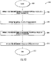
- FIG. 12 there is illustrated a flowchart generally at 300 that shows the method of operating the communications system 200 shown in FIG. 7 .
- the process starts (Block 302).
- the transmitter node 226 is operated to generate optical pulses at the pulse transmitter 240 (Block 304).
- the optical pulses are divided at the pulse divider 242 (Block 306).
- the receiver node 228 is operated to recombine the optical pulses at the pulse recombiner 254 (Block 308).
- the recombined pulses are received at the pulse receiver 256 (Block 310).
- the process ends (Block 312).
Landscapes
- Engineering & Computer Science (AREA)
- Physics & Mathematics (AREA)
- Signal Processing (AREA)
- Computer Networks & Wireless Communication (AREA)
- Electromagnetism (AREA)
- Theoretical Computer Science (AREA)
- Computer Security & Cryptography (AREA)
- Optics & Photonics (AREA)
- General Physics & Mathematics (AREA)
- Data Mining & Analysis (AREA)
- Pure & Applied Mathematics (AREA)
- Computing Systems (AREA)
- General Engineering & Computer Science (AREA)
- Mathematical Physics (AREA)
- Software Systems (AREA)
- Mathematical Optimization (AREA)
- Mathematical Analysis (AREA)
- Evolutionary Computation (AREA)
- Condensed Matter Physics & Semiconductors (AREA)
- Computational Mathematics (AREA)
- Artificial Intelligence (AREA)
- Optical Communication System (AREA)
Applications Claiming Priority (1)
| Application Number | Priority Date | Filing Date | Title |
|---|---|---|---|
| US17/179,562 US20230142045A1 (en) | 2021-02-19 | 2021-02-19 | Quantum communications system using pulse divider and associated methods |
Publications (1)
| Publication Number | Publication Date |
|---|---|
| EP4047863A1 true EP4047863A1 (de) | 2022-08-24 |
Family
ID=80682333
Family Applications (1)
| Application Number | Title | Priority Date | Filing Date |
|---|---|---|---|
| EP22156811.6A Pending EP4047863A1 (de) | 2021-02-19 | 2022-02-15 | Quantenkommunikationssystem mit impulsteiler und zugehörige verfahren |
Country Status (2)
| Country | Link |
|---|---|
| US (1) | US20230142045A1 (de) |
| EP (1) | EP4047863A1 (de) |
Families Citing this family (1)
| Publication number | Priority date | Publication date | Assignee | Title |
|---|---|---|---|---|
| US20220303130A1 (en) * | 2021-03-22 | 2022-09-22 | Ut-Battelle, Llc | Discrete variable quantum key distribution using conjugate homodyne detection |
Citations (5)
| Publication number | Priority date | Publication date | Assignee | Title |
|---|---|---|---|---|
| WO2008127451A2 (en) * | 2006-12-01 | 2008-10-23 | Cornell Research Foundation, Inc. | Divided-pulse amplification of short pulses |
| US10109976B2 (en) | 2014-01-21 | 2018-10-23 | Cornell University | Divided pulse lasers |
| US10374376B2 (en) | 2017-05-17 | 2019-08-06 | The Penn State Research Foundation | Divided pulse nonlinear optical sources |
| CN111130780A (zh) * | 2019-12-31 | 2020-05-08 | 无锡太湖学院 | 跨介质下设备无关及离散调制连续变量量子密钥分发系统 |
| GB2581528A (en) * | 2019-02-22 | 2020-08-26 | Toshiba Kk | A secure communication network |
Family Cites Families (2)
| Publication number | Priority date | Publication date | Assignee | Title |
|---|---|---|---|---|
| DE10338556A1 (de) * | 2003-08-22 | 2005-08-04 | Deutsche Telekom Ag | Verfahren sowie Anordnung zur Herstellung eines Hologramms |
| GB2536248B (en) * | 2015-03-10 | 2021-10-20 | Univ Bristol | Optical apparatus |
-
2021
- 2021-02-19 US US17/179,562 patent/US20230142045A1/en active Pending
-
2022
- 2022-02-15 EP EP22156811.6A patent/EP4047863A1/de active Pending
Patent Citations (6)
| Publication number | Priority date | Publication date | Assignee | Title |
|---|---|---|---|---|
| WO2008127451A2 (en) * | 2006-12-01 | 2008-10-23 | Cornell Research Foundation, Inc. | Divided-pulse amplification of short pulses |
| US8456736B2 (en) | 2006-12-01 | 2013-06-04 | Cornell University | Divided-pulse amplification of short pulses |
| US10109976B2 (en) | 2014-01-21 | 2018-10-23 | Cornell University | Divided pulse lasers |
| US10374376B2 (en) | 2017-05-17 | 2019-08-06 | The Penn State Research Foundation | Divided pulse nonlinear optical sources |
| GB2581528A (en) * | 2019-02-22 | 2020-08-26 | Toshiba Kk | A secure communication network |
| CN111130780A (zh) * | 2019-12-31 | 2020-05-08 | 无锡太湖学院 | 跨介质下设备无关及离散调制连续变量量子密钥分发系统 |
Non-Patent Citations (7)
| Title |
|---|
| ALI ANWAR ET AL: "Entangled Photon-Pair Sources based on three-wave mixing in bulk crystals", ARXIV.ORG, CORNELL UNIVERSITY LIBRARY, 201 OLIN LIBRARY CORNELL UNIVERSITY ITHACA, NY 14853, 30 July 2020 (2020-07-30), XP081729584 * |
| LAMB ET AL.: "Divided-Pulse Lasers", OPTICS LETTERS, vol. 39, no. 9, 2014, pages 2775 - 2777, XP001589650, DOI: 10.1364/OL.39.002775 |
| SCHILDKRAUT LUMI ET AL: "Investigating the Role of Spatiotemporal Optical Beam Profiles in Mixed Layer Oceanic Communication Channels", GLOBAL OCEANS 2020: SINGAPORE - U.S. GULF COAST, IEEE, 5 October 2020 (2020-10-05), pages 1 - 5, XP033896513, DOI: 10.1109/IEEECONF38699.2020.9388988 * |
| SHENG-KAI LIAO ET AL: "Satellite-to-ground quantum key distribution", ARXIV.ORG, CORNELL UNIVERSITY LIBRARY, 201 OLIN LIBRARY CORNELL UNIVERSITY ITHACA, NY 14853, 3 July 2017 (2017-07-03), XP081279476, DOI: 10.1038/NATURE23655 * |
| WANG TYAN-LIN ET AL: "Laser Beam Propagation Effects on Secure Key Rates for Satellite CV-QKD with Discrete Modulation", 2019 IEEE PHOTONICS CONFERENCE (IPC), IEEE, 29 September 2019 (2019-09-29), pages 1 - 2, XP033663213, DOI: 10.1109/IPCON.2019.8908317 * |
| ZHANG ET AL.: "Divided Pulse Soliton Self-Frequency Shift: A Multi-Color, Dual-Polarization, Power-Scalable, Broadly Tunable Optical Source", OPTICS LETTERS, vol. 42, no. 3, 2017, pages 502 - 505 |
| ZHOU ET AL.: "Divided-Pulse Amplification of Ultrashort Pulses", OPTICS LETTERS, vol. 32, no. 7, 2007, pages 871 - 873, XP001540441, DOI: 10.1364/OL.32.000871 |
Also Published As
| Publication number | Publication date |
|---|---|
| US20230142045A1 (en) | 2023-05-11 |
Similar Documents
| Publication | Publication Date | Title |
|---|---|---|
| US11451308B1 (en) | Quantum communications system having pulses divided into time bins and associated methods | |
| US8374350B2 (en) | Quantum communication system | |
| US7934132B2 (en) | Communication system and method for controlling the same | |
| US5515438A (en) | Quantum key distribution using non-orthogonal macroscopic signals | |
| JP4775820B2 (ja) | 非直交2状態量子暗号法及び盗聴探知のために量子ビット内及び量子ビット間干渉を有する装置 | |
| US11050559B2 (en) | Quantum communications system using Talbot effect image position and associated methods | |
| Townsend | Experimental investigation of the performance limits for first telecommunications-window quantum cryptography systems | |
| WO2009145392A1 (en) | System and method for quantum cryptography | |
| WO2015050623A2 (en) | Long-haul high rate quantum key distribution | |
| JP4777069B2 (ja) | 量子暗号通信システム及び方法、偏波/位相変調変換器並びに位相/偏波変調変換器 | |
| EP4107902B1 (de) | Verfahren zur verteilung von quantenschlüsseln, verfahren zur übertragung eines optischen signals, verfahren zur aufnahme eines optischen signals und empfänger eines optischen signals zur verteilung von quantenschlüsseln | |
| EP4047863A1 (de) | Quantenkommunikationssystem mit impulsteiler und zugehörige verfahren | |
| US11502758B2 (en) | Communications system using pulse divider and associated methods | |
| Townsend et al. | Secure optical communications systems using quantum cryptography | |
| EP3817274B1 (de) | Quantenkommunikationssystem mit quantenschlüsselverteilung und verwendung einer talbot-effekt-bildposition und zugehörige verfahren | |
| US11962689B2 (en) | Quantum communications system having at least one waveplate to alter pulse polarization and associated methods | |
| US11558123B2 (en) | Quantum communications system having stabilized quantum communications channel and associated methods | |
| Khan et al. | Analysis of achievable distances of BB84 and KMB09 QKD protocols | |
| Ma et al. | High speed quantum key distribution over optical fiber network system | |
| Rumyantsev et al. | Modeling of quantum key distribution system for secure information transfer | |
| Ryabtsev et al. | Element base of quantum informatics II: Quantum communications with single photons | |
| Curtacci et al. | Performance analysis of different multi-user optical passive networks for quantum cryptography applications | |
| Manninen | Practical Test of a Quantum Key Distribution System | |
| BARNETT | Secure optical communications systems using quantum cryptography | |
| Stumpf | Quantum Cryptography: A brief introduction to quantum key distribution |
Legal Events
| Date | Code | Title | Description |
|---|---|---|---|
| PUAI | Public reference made under article 153(3) epc to a published international application that has entered the european phase |
Free format text: ORIGINAL CODE: 0009012 |
|
| STAA | Information on the status of an ep patent application or granted ep patent |
Free format text: STATUS: REQUEST FOR EXAMINATION WAS MADE |
|
| 17P | Request for examination filed |
Effective date: 20220215 |
|
| AK | Designated contracting states |
Kind code of ref document: A1 Designated state(s): AL AT BE BG CH CY CZ DE DK EE ES FI FR GB GR HR HU IE IS IT LI LT LU LV MC MK MT NL NO PL PT RO RS SE SI SK SM TR |
|
| STAA | Information on the status of an ep patent application or granted ep patent |
Free format text: STATUS: EXAMINATION IS IN PROGRESS |