EP4047825A1 - Nahfeldkommunikationsvorrichtung mit einem ereignisdetektor - Google Patents
Nahfeldkommunikationsvorrichtung mit einem ereignisdetektor Download PDFInfo
- Publication number
- EP4047825A1 EP4047825A1 EP21305206.1A EP21305206A EP4047825A1 EP 4047825 A1 EP4047825 A1 EP 4047825A1 EP 21305206 A EP21305206 A EP 21305206A EP 4047825 A1 EP4047825 A1 EP 4047825A1
- Authority
- EP
- European Patent Office
- Prior art keywords
- nfc
- wlc
- unit
- events
- under charge
- Prior art date
- Legal status (The legal status is an assumption and is not a legal conclusion. Google has not performed a legal analysis and makes no representation as to the accuracy of the status listed.)
- Pending
Links
- 238000004891 communication Methods 0.000 title claims abstract description 43
- 238000001514 detection method Methods 0.000 claims abstract description 59
- 238000012545 processing Methods 0.000 claims abstract description 42
- 238000000034 method Methods 0.000 claims abstract description 22
- 238000001914 filtration Methods 0.000 claims description 8
- 238000012546 transfer Methods 0.000 description 18
- 230000000694 effects Effects 0.000 description 14
- 230000009471 action Effects 0.000 description 7
- 230000008859 change Effects 0.000 description 6
- 230000011664 signaling Effects 0.000 description 5
- 238000013461 design Methods 0.000 description 4
- 238000005516 engineering process Methods 0.000 description 4
- 230000000630 rising effect Effects 0.000 description 4
- 230000035945 sensitivity Effects 0.000 description 4
- 230000001960 triggered effect Effects 0.000 description 4
- 238000010586 diagram Methods 0.000 description 3
- 238000012544 monitoring process Methods 0.000 description 3
- 230000008569 process Effects 0.000 description 3
- 230000004044 response Effects 0.000 description 3
- 230000004913 activation Effects 0.000 description 2
- 230000005540 biological transmission Effects 0.000 description 2
- 230000008878 coupling Effects 0.000 description 2
- 238000010168 coupling process Methods 0.000 description 2
- 238000005859 coupling reaction Methods 0.000 description 2
- 238000011161 development Methods 0.000 description 2
- 238000003708 edge detection Methods 0.000 description 2
- 238000004519 manufacturing process Methods 0.000 description 2
- 238000007781 pre-processing Methods 0.000 description 2
- 238000013459 approach Methods 0.000 description 1
- 230000006399 behavior Effects 0.000 description 1
- 230000008901 benefit Effects 0.000 description 1
- 238000012508 change request Methods 0.000 description 1
- 230000001419 dependent effect Effects 0.000 description 1
- 230000001976 improved effect Effects 0.000 description 1
- 230000006872 improvement Effects 0.000 description 1
- 230000001939 inductive effect Effects 0.000 description 1
- 238000012067 mathematical method Methods 0.000 description 1
- 238000003672 processing method Methods 0.000 description 1
- 230000009467 reduction Effects 0.000 description 1
Images


Classifications
-
- H04B5/79—
-
- H04B5/72—
-
- H—ELECTRICITY
- H02—GENERATION; CONVERSION OR DISTRIBUTION OF ELECTRIC POWER
- H02J—CIRCUIT ARRANGEMENTS OR SYSTEMS FOR SUPPLYING OR DISTRIBUTING ELECTRIC POWER; SYSTEMS FOR STORING ELECTRIC ENERGY
- H02J50/00—Circuit arrangements or systems for wireless supply or distribution of electric power
- H02J50/80—Circuit arrangements or systems for wireless supply or distribution of electric power involving the exchange of data, concerning supply or distribution of electric power, between transmitting devices and receiving devices
-
- H04B5/73—
-
- H—ELECTRICITY
- H04—ELECTRIC COMMUNICATION TECHNIQUE
- H04W—WIRELESS COMMUNICATION NETWORKS
- H04W52/00—Power management, e.g. TPC [Transmission Power Control], power saving or power classes
- H04W52/02—Power saving arrangements
- H04W52/0209—Power saving arrangements in terminal devices
- H04W52/0261—Power saving arrangements in terminal devices managing power supply demand, e.g. depending on battery level
- H04W52/0274—Power saving arrangements in terminal devices managing power supply demand, e.g. depending on battery level by switching on or off the equipment or parts thereof
Definitions
- the present disclosure relates to a near field communication device. Furthermore, the present disclosure relates to a corresponding method of operating a near field communication device.
- NFC Near field communication
- a primary device may generate a radio frequency (RF) field at a frequency of 13.56 MHz to power a secondary device. Modulation techniques are used to communicate in both directions.
- the secondary device may be a passive device (e.g., a tag or a transponder) or an active, typically battery-powered device.
- An RF field generated by an NFC reader can be used to charge the battery of the secondary device. This process is referred to as wireless charging.
- a near field communication (NFC) device comprising: an NFC unit configured to charge an external device under charge by transferring power to said device under charge through an NFC channel; a detection unit configured to detect predefined events occurring on the NFC channel when said power is being transferred to the device under charge; a processing unit configured to control the transferring of power to the device under charge in dependence on the events detected by the detection unit.
- NFC near field communication
- the processing unit is further configured to disable, at least in part, a receiver comprised in the NFC unit when said power is being transferred to the device under charge.
- the processing unit is further configured to enable the receiver in dependence on the events detected by the detection unit.
- the processing unit is further configured to interrupt the transferring of power to the device under charge in dependence on the events detected by the detection unit or to conclude an ongoing continuous wave charging phase in dependence on the events detected by the detection unit.
- the predefined events include at least one of the following events: a data frame transmitted by the device under charge; a removal of the device under charge from the NFC channel; another communication device being brought into close proximity of the NFC unit.
- the detection unit includes a receiver signal monitor configured to monitor signal changes in a receiver path of the NFC unit, wherein said signal changes in the receiver path are indicative of one or more of the predefined events.
- the detection unit includes a transmitter current monitor configured to monitor signal changes in a supply current path to a transmitter of the NFC unit, wherein said signal changes in the supply current path are indicative of one or more of the predefined events.
- the detection unit further includes a decoder configured to decode inputs provided by the receiver signal monitor and the transmitter current monitor into detected events, and to notify the processing unit of said detected events.
- the decoder has settings which are programmable or configurable by a user.
- the processing unit is configured to enable and disable the decoder.
- the decoder includes a filtering unit configured to filter the inputs provided by the receiver signal monitor and the transmitter current monitor before said inputs are decoded.
- the decoder is configured to decode the inputs by detecting predefined patterns in the signal changes in the receiver path and/or the supply current path.
- the settings include one or more thresholds used for detecting the predefined patterns in said signal changes.
- a method of operating a near field communication (NFC) device comprising an NFC unit, a detection unit and a processing unit, the method comprising: charging, by the NFC unit, an external device under charge by transferring power to said device under charge through an NFC channel; detecting, by the detection unit, predefined events occurring on the NFC channel when said power is being transferred to the device under charge; controlling, by the processing unit, the transferring of power to the device under charge in dependence on the events detected by the detection unit.
- NFC near field communication
- NFC Near field communication
- a primary device may generate a radio frequency (RF) field at a frequency of 13.56 MHz to power a secondary device. Modulation techniques are used to communicate in both directions.
- the secondary device may be a passive device (e.g., a tag or a transponder) or an active, typically battery-powered device.
- An RF field generated by an NFC reader can be used to charge the battery of the secondary device. This process is referred to as wireless charging.
- Typical implementations of NFC direct wireless charging make use of a WLC-P (wireless charging poller) device and a WLC-L (wireless charging listener) device.
- the wireless charging poller may be a standalone reader device which is configured to charge the battery of the wireless charging listener, i.e. a secondary accessory device such as a watch or fitness tracker.
- Basic standalone WLC-P implementations typically have a single antenna for WLC use cases.
- general NFC devices and especially NFC-enabled mobile devices can support WLC-P use cases in parallel to conventional NFC use cases (such as payment, ticketing, access control, and tag reading applications) with a single NFC controller connected to NFC and WLC antennas.
- time multiplexing methods may be used to enable that only one antenna is actively connected to the NFC controller's radio frequency (RF) modem (i.e., the controller's NFC transceiver).
- RF radio frequency
- an NFC controller's RF modem may be connected to multiple antennas, including NFC and WLC antennas.
- an NFC controller is connected to a WLC antenna through which the wireless charging operation can be performed.
- the term "WLC activity" refers to a scenario in which a primary device acts as a WLC-P to charge a WLC-L using a WLC antenna.
- the duration of typical WLC activities is between several minutes up to several hours. Therefore, the WLC antenna may have to be used by the transmitter of the NFC controller's transceiver for a relatively long time to transfer power to the secondary device.
- the receiver of the RF modem should also remain active, because it should be able to receive, for example, control messages relating to the WLC activity from the secondary device. This, in turn, increases the power consumption of the wireless charging device.
- power saving measures can be implemented during the RF field emission of the wireless charging operation, the NFC transceiver should still be response to external RF events.
- Fig. 1 shows an example of an NFC-based wireless charging system 100.
- the system 100 includes a device with WLC-P functionality 102 configured to transfer power to a device with WLC-L functionality 108 through an NFC channel established between the devices 102, 108.
- the device with WLC-P functionality 102 comprises an NFC unit with WLC-P functionality 104
- the device with WLC-L functionality 108 comprises an NFC unit with WLC-L functionality 110.
- the device with WLC-P functionality 102 comprises a charger battery 106
- the device with WLC-L functionality 108 comprises a charged battery 112 (i.e., a battery that can be charged by the wirelessly transferred power).
- NFC Near field communication
- RFID radio frequency identification
- WLC Wireless Charging
- WLC-L WLC Listener
- WLC-L devices include accessories, such as fitness trackers, stylus pens or earbuds.
- a wireless charging activity may take from several minutes up to several hours.
- a continuous wave emission takes place.
- no RF communication is performed.
- the WLC-P will poll the WLC-L and check for updates. For instance, the WLC-P will verify whether the WLC-L has reached a "battery full" status. The time duration between such communication polls may take from some seconds up to several minutes.
- the WLC-L is usually aware of the battery status and the required RF power to successfully complete the wireless charging operation. However, if the WLC-L wants to trigger a change in RF power emitted by WLC-P, it has to wait until the WLC-P is checking for updates.
- the WLC-L which may be a card device, should wait for a request from the WLC-P, which may be a reader. Still, the WLC-L may be able to transmit a "WLC Stop Request" frame to trigger the WLC-P to ask WLC-related updates, in order to prevent long latencies, for example between the moment the WLC-L has an intention to request a change in the transmitted power and the moment the WLC-P becomes aware of this intention.
- a "WLC Stop Request” may be regarded as a communication event that should be detected by the WLC-P.
- WLC-P Another event which may have to be detected by the WLC-P is the removal of the WLC-L from the NFC channel through which the wireless power transfer (WPT) is performed.
- WPT wireless power transfer
- the WLC-P will detect removal of a WLC-L only as early as it performs the next polling communication. In other words, before this polling communication which is initiated by the WLC-P itself, the WLC-P will not receive any indication as to whether the WLC-L has been removed. This may cause a delay between the moment that the WLC-L is removed and the moment that the WLC-P disables the RF field. This delay, which may amount to several minutes, may cause an increased power consumption and a negative user experience (e.g., the NFC interface may be blocked).
- Another event which may have to be detected by the WLC-P is the close proximity of another communication device to the NFC transceiver of the WLC-P.
- This other communication device may for example be a tag, which enters the RF field generated by the WLC-P while the WLC-L is being charged.
- the WLC-P may emit RF fields above the H-field limits defined for RF communication by the NFC Forum. This allows faster energy transfer, but it can destroy tags which are brought into the proximity of the WLC-P device during the WLC activity. Therefore, the WLC-P should be able to detect the resonant device which is presented to the WLC-P.
- This device is referred to as a Foreign Object (FO) in the WLC specification of the NFC Forum.
- the NFC Forum defines a background Foreign Object Detection (bFOD) as a method to detect the approach of additional counterparts, which detection should trigger a power reduction of strong emitted RF fields. Additionally, this method may be used to detect RF coupling changes caused by the removal of the WLC-L from the NFC channel.
- bFOD Foreign Object Detection
- said WLC specification defines the concept of bFOD, but not how to realize it on or integrate it into real hardware. However, it is assumed that the skilled person will be able to implement it in hardware.
- the RF modem receiver chain typically includes a low-noise, high-performance analog chain and an optimized digital signal processing (DSP) unit for regular reader-mode activities.
- DSP digital signal processing
- reader-mode activities cover various use cases, tag and accessory reading and Bluetooth pairing triggered through an NFC channel.
- the RF modem includes a receiver as well as a transmitter, it may also be referred to as a transceiver.
- the high-performance receiver of the RF modem consumes a certain amount of power. Typical values for the RM modem's power dissipation are around 30 to 100 mW, depending on the device supply voltage.
- NFC-based wireless charging is often used to charge accessories with a received power between 100 mW and 2 W.
- the received power may be more than 15 W, which is common when wireless charging operations are performed in accordance with the Qi standard.
- Qi is an open interface standard that defines wireless power transfer using inductive charging over distances of up to 4 cm, developed by the Wireless Power Consortium.
- the end-to-end power efficiency is defined by the ratio between the input power of the charged accessory and the required power provided by the charger battery. If this efficiency is too low, the WLC use case may not be fully enabled and the user experience may be negatively affected. Therefore, the excess power in the WLC-P should be minimized.
- the near field communication device may be used to efficiently perform wireless power transfer (WPT) operations to charge an external device under charge.
- WPT wireless power transfer
- Fig. 2 shows an illustrative embodiment of an NFC device 200.
- the NFC device 200 comprises an NFC unit 202, a detection unit 204 and a processing unit 206.
- the NFC unit 202 is configured to charge an external device under charge (not shown) by transferring power to said device under charge through an NFC channel.
- the detection unit 204 is configured to detect predefined events occurring on the NFC channel when said power is being transferred to the device under charge.
- the processing unit 206 is configured to control the transferring of power to the device under charge in dependence on the events detected by the detection unit 204. In this way, the wireless power transfer operation may be controlled dynamically by adapting the operation as early as possible, without sending for example an explicit request for an update on the status of the device under charge.
- the NFC unit 202 may be an NFC transceiver of the kind set forth, i.e. a device which includes both a receiver and a transmitter. In other embodiments (not shown), the NFC unit 202 may only comprise a transmitter. Furthermore, it is noted that the term "device under charge” refers to a device that is being charged by said NFC unit.
- the processing unit 206 is further configured to disable, at least in part, a receiver comprised in the NFC unit 202 when said power is being transferred to the device under charge. In this way, the power consumed by the NFC device 200 may be further reduced.
- the high-performance receiver NFC unit 202 does not need to be used for this purpose. It is noted that disabling the receiver may be realized by switching off, at least in part, the receiver or putting the receiver at least in part in a power-down state, such as a sleep state. For example, only a set of submodules of the receiver may be switched off, while other submodules may remain active.
- the processing unit 206 is further configured to enable the receiver in dependence on the events detected by the detection unit 204. In this way, the receiver is quickly put into operation if the detected events indicate that its functionality is needed.
- the processing unit 206 is further configured to interrupt the transferring of power to the device under charge in dependence on the events detected by the detection unit 204 or to conclude an ongoing continuous wave charging phase in dependence on the events detected by the detection unit. In this way, the wireless power transfer operation may be stopped as early as possible, such that no energy is wasted on a continuation of the wireless power transfer operation if the detected events indicate that the operation does not need to be continued. Whether the transferring of power is interrupted or the continuous wave charging phase is concluded, may depend on the type of event which is detected. For instance, after a stop pattern event, the transferring of power as such may not be interrupted, because this might cause an RF field reset.
- the most appropriate action may be to stop the ongoing charging cycle and to perform communication with the counterpart.
- the correct handling may be to disable the RF field (i.e., to interrupt the transferring of power) and to enable it again to poll for any present NFC counterparts.
- the predefined events include at least one of the following events: a data frame transmitted by the device under charge; a removal of the device under charge from the NFC channel; another communication device being brought into close proximity of the NFC unit 202.
- These predefined events are particularly suitable events for signaling to the processing unit that a certain action should be taken.
- the data frame may comprise a stop pattern that indicates that the wireless power transfer should be interrupted.
- a removal of the device under charge may indicate that the wireless power transfer should be interrupted.
- the close proximity of another communication device may indicate that at least the strength of the emitted HF field should be reduced, to avoid damaging the other communication device.
- the detection unit 204 includes a receiver signal monitor configured to monitor signal changes in a receiver path of the NFC unit 202, wherein said signal changes in the receiver path are indicative of one or more of the predefined events. In this way, the detection of the predefined events is facilitated. In particular, by monitoring signal changes in the receiver path, predefined events can be detected while the receiver of the NFC unit 202 is not in an active state. Furthermore, in one or more embodiments, the detection unit 204 includes a transmitter current monitor configured to monitor signal changes in a supply current path to a transmitter of the NFC unit 202, wherein said signal changes in the supply current path are indicative of one or more of the predefined events. In this way, the detection of the predefined events is facilitated. In particular, by monitoring signal changes in the supply current path to the transmitter, predefined events can be detected while the receiver of the NFC unit 202 is not in an active state.
- the detection unit 204 further includes a decoder configured to decode inputs provided by the receiver signal monitor and the transmitter current monitor into detected events, and to notify the processing unit 206 of said detected events. This further facilitates the detection of the predefined events.
- the decoder has settings which are programmable or configurable by a user. In this way, the detection of the predefined events can easily be optimized by the user.
- the processing unit 206 is configured to enable and disable the decoder. In this way, the processing unit 206 can easily control whether the detection of predefined events is enabled or disabled.
- the decoder includes a filtering unit configured to filter the inputs provided by the receiver signal monitor and the transmitter current monitor before said inputs are decoded. In this way, the signal-to-noise ratio of the inputs can be increased, which may reduce the likelihood of wrongly detected events.
- the decoder is configured to decode the inputs by detecting predefined patterns in the signal changes in the receiver path and/or the supply current path. In this way, the detection of the predefined events is further facilitated.
- the programmable or configurable decoder settings include one or more thresholds used for detecting the predefined patterns in said signal changes. This further facilitates optimizing the detection of the predefined events.
- Fig. 3 shows an illustrative embodiment of a method 300 of operating an NFC device.
- the method 300 includes the following steps.
- an NFC unit of an NFC device charges an external device under charge by transferring power to said device under charge through an NFC channel.
- a detection unit of the NFC device detects predefined events occurring on the NFC channel when said power is being transferred to the device under charge.
- a processing unit of the NFC device controls the transferring of power to the device under charge in dependence on the events detected by the detection unit.
- the wireless power transfer operation may thereby be controlled dynamically by adapting the operation as early as possible, without sending for example an explicit request for an update on the status of the device under charge.
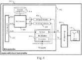
- Fig. 4 shows an illustrative embodiment of a device 400 with wireless charging poller (WLC-P) functionality.
- the device 400 includes an NFC controller 402 operatively coupled to an RF matching circuit 416 via a receiver (RX) path and a transmitter (TX) path.
- the device 400 further includes a WLC-P antenna 418 operatively coupled to the RF matching circuit 416.
- the WLC-P antenna 418 enables establishing an NFC channel through which power can be transferred to an external device under charge (not shown).
- the NFC controller 402 includes an RF modem 404 comprising a receiver and a transmitter, which enable receiving and transmitting signals to the external device under charge.
- the NFC controller 402 includes a receiver signal monitor 406 and a transmitter current monitor 408 that facilitate the detection of predefined events in the manner described above.
- the NFC controller 402 includes a WLC decoder and a processing unit 412 of the kind set forth above.
- a detection unit is configured to predefined events occurring on an NFC channel when power is being transferred to the device under charge.
- a predefined event may for example be the transmission of a so-called "WPT Stop Request" by the device under charge.
- the format of this request is defined in the WLC Technical Specification issued by the NFC Forum.
- the "WPT Stop Request” is defined as a sequence of eight symbols consisting of a "pattern S”.
- pattern S refers to a modulation symbol, and a plurality of "pattern S” symbols may form a WPT stop pattern.
- the "pattern S" symbol has a typical duration of 2 ms and half of the symbol has a positive or negative RF modulation.
- a symbol rate of approximately 500 Hz is very slow compared to typical bit rates found in NFC communication.
- typical bit rates for NFC are 106 kbps for the signaling types NFC-A and NFC-B and 26 kbps for the signaling type NFC-V.
- the latter signaling type may also be referred to as the "ICODE" signaling type, because it is used in so-called ICODE ® tags.
- Other predefined events are the removal of the WLC-L from the NFC channel and the close proximity of so-called foreign objects to the WLC-P. These predefined events result in load changes on the WLC-P antenna, which can be detected using the receiver signal monitor 406 or a transmitter current monitor 408.
- RF antenna load changes on the WLC-P antenna 418 result in an observable correlating change in the RF modem's TX supply current and RX input voltage envelope. It is noted that this change may be the same if WLC-L is removed or a foreign object is presented. Since the "pattern S" is also generated by load modulation on the NFC channel, it has a similar effect in terms of load changes on the WLC-P antenna 418 as the removal of the WLC-L and the proximity of a foreign object.
- the aforementioned WLC Technical Specification also describes examples of actions that may be taken by the processing unit 412 in response to detecting the predefined events. These examples include the following actions. After a WLC stop pattern has been received, the WPT phase (continuous wave emission) and the WLC cycle are caused to end early. Furthermore, the WLC-P polls again for a WLC-L, which allows the WLC-L to update the WLC-P with the information that triggered the transmission of the stop pattern. This may allow the WLC-L to indicate that its battery is full, but also to request an increase or decrease of the RF field strength depending on the charge state of its battery.
- the WLC-P After a bFOD event has been detected, the WLC-P will stop the ongoing WLC cycle in order to prevent damage to the FO being resonant at 13.56 MHz. Furthermore, the WLC-P will check which FC counterparts are present in its vicinity. This is called "Polling FOD" and may include an RF field reset as well as a new activation sequence.
- the device 400 shown in Fig. 4 includes an NFC controller 402, but the presently disclosed concept is also applicable to lower level NFC front-end designs.
- the transmitter of the RF modem 404 may be used as a source to generate the RF field and a modulated reader signal.
- the receiver of the RF modem 404 may be used to receive counterpart load modulation signals for NFC communication.
- the receiver chain implementation may include an analog and digital portion.
- NFC communication systems should typically have a very high dynamic range including a high receiver sensitivity performance to detect low load modulation amplitude levels of loosely coupled counterparts (such as NFC tags at a distance of a few centimeters).
- a WLC activity typically has a very high coupling between the WLC-P and WLC-L to achieve the power transfer and a high-power efficiency.
- the high RX detection sensitivity for regular reader mode reception results in a significant power consumption.
- this high RX detection sensitivity may not be needed.
- the RF modem's receiver, or sub-blocks of it may be enabled or disabled by a control signal.
- the NFC controller 402 has units 406, 408 to monitor receiver input signals and to monitor the transmitter supply current. It is noted that specific implementations may include only one of these units 406, 408. The digitized outputs of these units 406, 408 are provided to the WLC decoder 410.
- the WLC decoder 410 may have a user-programmable decoder configuration 414, which may be stored in a non-volatile memory.
- the decoder configuration 414 may include, for example, decoder threshold settings, timing definitions, and settings that define which input signal monitor should be used. Additionally, an enable signal may be used to power down the WLC decoder 410 when it is not needed.
- the RF modem's receiver input impedance may have to be kept constant while the WLC decoder 410 is active. Otherwise, input impedance changes may have a negative impact on the WLC decoder's detection performance. It is noted that WLC decoder implementations that rely only on the TX current as input signal may have an optimal power efficiency gain, because the complete receiver can be disabled.
- the processing unit 412 may control both the WLC decoder 410 and the RF modem 404. Furthermore, any RF events detected by the WLC decoder 410 may be handled by the processing unit 412, for example by taking actions as defined in the aforementioned WLC Technical Specification. It is noted that this specification defines that the WLC activity uses looped WLC cycles after initial activation and setup. Each WLC cycle consists of an RF communication phase called WCC (wireless charging control) for exchanging charging control messages (power change requests, battery full indication, etc.) and the main wireless power transfer (WPT) phase.
- WCC wireless charging control
- WPT main wireless power transfer
- the WPT phase does not include regular NFC RF communication, but the following events may be detected during this phase: (i) WPT Stop Pattern frames sent by the WLC-L, (ii) removal of the WLC-L from the NFC channel, and (iii) a foreign object (FO) entering the operating volume of the WLC-P.
- Fig. 5 shows an illustrative embodiment of a timing diagram 500 of a near field communication device.
- the system may shut down the main RF modem's receiver to save power and to increase the end-to-end efficiency.
- the NFC controller may implement further power saving measures in addition to shutting down the receiver.
- the NFC controller may enable the WLC decoder for RF event monitoring. During this time the WLC decoder monitors input metrics and raises corresponding RF events to the processing unit, which may take an appropriate action. For instance, the processing unit may disable the WLC decoder after any detected RF event and re-enable the RF modem's receiver for communication purposes.
- Fig. 6 shows an illustrative embodiment of a wireless charging (WLC) decoder 600.
- the WLC decoder 600 comprises a control unit 602, a signal selection and pre-processing section, a main processing section and an event reporting unit 616.
- the control unit 602 is used to configure sub-blocks as defined in non-volatile memory by using control signals. These control signals are shown in Fig. 6 as dashed lines and are explained below for every related block.
- the signal selection and pre-processing section includes two multiplexers 604, 608 and a digital filtering unit 606.
- the first multiplexer 604 allows to select the input signal for the WLC decoder 600. Configurable digital filtering can be used to pre-process the input signal.
- a second multiplexer 608 selects either the digitally filtered input signal or the raw input signal.
- the main processing section includes an edge detector and debouncing unit 610, followed by a "pattern S" validator 612 and a "pattern S” counter 614.
- the edge detector and debouncing unit 610 uses digital signal processing methods to detect significant load changes in the observed signal trace and signals the detected load changes to the "pattern S" validator 612.
- a basic implementation may include a threshold-based comparator with a debouncer to prevent noise in the input signal, which may cause false alarms (i.e., wrongly detected events).
- debouncing refers to a method to filter out "glitches” (i.e., short time outliers caused by for example interference or noise) in signals, thereby preventing that an edge detection is inadvertently triggered.
- a simple implementation of a debouncer may require that a signal stays above a threshold for a configurable minimum time before declaring this as an edge crossing.
- An improved implementation may use mathematical methods, such as methods based on first derivatives, to detect edges.
- the edge detector and debouncing unit 610 may take both rising edges and falling edges into account.
- the "pattern S" validator 612 verifies the timing between the detected edges. Only if the time between detected rising and falling edges is within a configurable target range, a "pattern S" symbol may be regarded as detected. This is signaled to the "pattern S" counter 614, which increments after every detected "pattern S” symbol. It is noted that the control unit 602 may reset the counter after the WLC decoder 600 has been enabled.
- the event reporting unit 616 receives detected RF events like "Modulation detected”, “FO detected”, “WPT Stop Pattern Detected” from the main processing section.
- An event-reason filtering configuration may be available to control which RF events are provided as WLC decoder output.
- the output may be an interrupt signal to a processing unit and/or a status signal.
- the WLC decoder 600 may have different detection thresholds (e.g., detection sensitivity configuration values) for "pattern S" detection and FO detection.
- the FO detection may also be related to the removal of a WLC-L. That is to say, the load change effect observed by the WLC-P when a FO is presented may be similar to the load change effect observed when the WLC-L is removed.
- reporting of the "FO detected" event may also be triggered by the removal of the WLC-L.
- the resulting system handling may also be the same: in both cases the action to be taken may be to check which NFC counterparts are present in the vicinity of the WLC-P's antenna.
- Fig. 7 shows an illustrative embodiment of a wireless power transfer (WPT) stop request decoding sequence 700.
- WPT wireless power transfer
- the input signal trace and WLC decoder internal status signals used by the main decoder section are shown.
- Low and high thresholds are defined to allow a sensitive symbol detection above intrinsic signal noise levels.
- Rising and falling edge detection events are signaled to the aforementioned "pattern S" validator. Note that debouncing may be applied to prevent false alarms.
- the "pattern S" validator signals a "pattern S” detected event, if the preceding time differences between rising and falling edges are within the configured time ranges.
Priority Applications (3)
| Application Number | Priority Date | Filing Date | Title |
|---|---|---|---|
| EP21305206.1A EP4047825A1 (de) | 2021-02-19 | 2021-02-19 | Nahfeldkommunikationsvorrichtung mit einem ereignisdetektor |
| CN202210019016.1A CN114978244A (zh) | 2021-02-19 | 2022-01-04 | 具有事件检测器的近场通信装置 |
| US17/649,421 US11916616B2 (en) | 2021-02-19 | 2022-01-31 | Near field communication device having an event detector |
Applications Claiming Priority (1)
| Application Number | Priority Date | Filing Date | Title |
|---|---|---|---|
| EP21305206.1A EP4047825A1 (de) | 2021-02-19 | 2021-02-19 | Nahfeldkommunikationsvorrichtung mit einem ereignisdetektor |
Publications (1)
| Publication Number | Publication Date |
|---|---|
| EP4047825A1 true EP4047825A1 (de) | 2022-08-24 |
Family
ID=74856799
Family Applications (1)
| Application Number | Title | Priority Date | Filing Date |
|---|---|---|---|
| EP21305206.1A Pending EP4047825A1 (de) | 2021-02-19 | 2021-02-19 | Nahfeldkommunikationsvorrichtung mit einem ereignisdetektor |
Country Status (3)
| Country | Link |
|---|---|
| US (1) | US11916616B2 (de) |
| EP (1) | EP4047825A1 (de) |
| CN (1) | CN114978244A (de) |
Cited By (1)
| Publication number | Priority date | Publication date | Assignee | Title |
|---|---|---|---|---|
| WO2024064013A1 (en) * | 2022-09-19 | 2024-03-28 | Apple Inc. | Foreign object detection during wireless power transmission |
Families Citing this family (1)
| Publication number | Priority date | Publication date | Assignee | Title |
|---|---|---|---|---|
| US20220294597A1 (en) * | 2021-03-10 | 2022-09-15 | Qualcomm Incorporated | Cell-group slot format indication (sfi) |
Citations (2)
| Publication number | Priority date | Publication date | Assignee | Title |
|---|---|---|---|---|
| US20130062959A1 (en) * | 2011-09-09 | 2013-03-14 | Qualcomm Incorporated | Systems and methods for detecting and identifying a wireless power device |
| US20160126752A1 (en) * | 2013-06-17 | 2016-05-05 | Nokia Technologies Oy | Method and apparatus for wireless power transfer |
Family Cites Families (6)
| Publication number | Priority date | Publication date | Assignee | Title |
|---|---|---|---|---|
| US8238823B2 (en) | 2005-02-09 | 2012-08-07 | Nxp B.V. | Method for ensuring a secure NFC functionality of a wireless mobile communication device and wireless mobile communication device having a secure NFC functionality |
| KR20130081620A (ko) | 2012-01-09 | 2013-07-17 | 주식회사 케이더파워 | 무선 충전 시스템용 수신기 |
| CN104578219A (zh) | 2013-10-25 | 2015-04-29 | 陈业军 | 一种具有近场通信功能的无线充电底座 |
| US10566843B2 (en) * | 2014-07-15 | 2020-02-18 | Qorvo Us, Inc. | Wireless charging circuit |
| EP3748614A1 (de) * | 2019-06-03 | 2020-12-09 | Nxp B.V. | Interaktives poster |
| US10819394B1 (en) | 2019-10-04 | 2020-10-27 | Nxp B.V. | Detection of NFC proximity IC cards (PICCs) during wireless charging |
-
2021
- 2021-02-19 EP EP21305206.1A patent/EP4047825A1/de active Pending
-
2022
- 2022-01-04 CN CN202210019016.1A patent/CN114978244A/zh active Pending
- 2022-01-31 US US17/649,421 patent/US11916616B2/en active Active
Patent Citations (2)
| Publication number | Priority date | Publication date | Assignee | Title |
|---|---|---|---|---|
| US20130062959A1 (en) * | 2011-09-09 | 2013-03-14 | Qualcomm Incorporated | Systems and methods for detecting and identifying a wireless power device |
| US20160126752A1 (en) * | 2013-06-17 | 2016-05-05 | Nokia Technologies Oy | Method and apparatus for wireless power transfer |
Cited By (1)
| Publication number | Priority date | Publication date | Assignee | Title |
|---|---|---|---|---|
| WO2024064013A1 (en) * | 2022-09-19 | 2024-03-28 | Apple Inc. | Foreign object detection during wireless power transmission |
Also Published As
| Publication number | Publication date |
|---|---|
| US11916616B2 (en) | 2024-02-27 |
| CN114978244A (zh) | 2022-08-30 |
| US20220271798A1 (en) | 2022-08-25 |
Similar Documents
| Publication | Publication Date | Title |
|---|---|---|
| US11916616B2 (en) | Near field communication device having an event detector | |
| KR101897325B1 (ko) | 무선 전력 수신기들에서 전압을 제한하기 위한 시스템들 및 방법들 | |
| US9553637B2 (en) | Near field communications (NFC) and proximity sensor for portable devices | |
| US10734841B2 (en) | System and method for facilitating avoidance of wireless charging cross connection | |
| JP6148310B2 (ja) | ワイヤレス給電ピアツーピア通信 | |
| JP6359556B2 (ja) | コロケートされた送信機とのワイヤレス電力システムにおける通信の解決 | |
| CN109478802B (zh) | 用于后续的接收器的无线功率充电的装置和方法 | |
| US11784681B2 (en) | Communication device and operating method | |
| WO2021102725A1 (en) | System and method for distinguishing between active and passive nfc devices | |
| US10492140B2 (en) | Auxiliary path for low-power device wakeup | |
| US20220141772A1 (en) | Rf communication devices and operating methods | |
| TWI765193B (zh) | 訊號傳輸系統、客戶裝置及其訊號的偵測方法 | |
| JP2017216707A (ja) | 可搬装置のための近距離場通信(nfc)および近接センサー | |
| JP2014103788A (ja) | 充電器、制御プログラム | |
| US11190237B2 (en) | Wireless communication device for detecting card | |
| KR101192168B1 (ko) | 근거리 무선통신방법 | |
| CN117811224A (zh) | 用于对无线充电监听器装置执行存在检查的方法和装置 |
Legal Events
| Date | Code | Title | Description |
|---|---|---|---|
| PUAI | Public reference made under article 153(3) epc to a published international application that has entered the european phase |
Free format text: ORIGINAL CODE: 0009012 |
|
| STAA | Information on the status of an ep patent application or granted ep patent |
Free format text: STATUS: THE APPLICATION HAS BEEN PUBLISHED |
|
| AK | Designated contracting states |
Kind code of ref document: A1 Designated state(s): AL AT BE BG CH CY CZ DE DK EE ES FI FR GB GR HR HU IE IS IT LI LT LU LV MC MK MT NL NO PL PT RO RS SE SI SK SM TR |
|
| STAA | Information on the status of an ep patent application or granted ep patent |
Free format text: STATUS: REQUEST FOR EXAMINATION WAS MADE |
|
| 17P | Request for examination filed |
Effective date: 20230224 |
|
| RBV | Designated contracting states (corrected) |
Designated state(s): AL AT BE BG CH CY CZ DE DK EE ES FI FR GB GR HR HU IE IS IT LI LT LU LV MC MK MT NL NO PL PT RO RS SE SI SK SM TR |