EP4047813B1 - Regulierungsmodul für elektrisch umlaufende maschine - Google Patents
Regulierungsmodul für elektrisch umlaufende maschine Download PDFInfo
- Publication number
- EP4047813B1 EP4047813B1 EP22154492.7A EP22154492A EP4047813B1 EP 4047813 B1 EP4047813 B1 EP 4047813B1 EP 22154492 A EP22154492 A EP 22154492A EP 4047813 B1 EP4047813 B1 EP 4047813B1
- Authority
- EP
- European Patent Office
- Prior art keywords
- module
- machine
- rotor
- stator
- output quantity
- Prior art date
- Legal status (The legal status is an assumption and is not a legal conclusion. Google has not performed a legal analysis and makes no representation as to the accuracy of the status listed.)
- Active
Links
Images
Classifications
-
- H—ELECTRICITY
- H02—GENERATION; CONVERSION OR DISTRIBUTION OF ELECTRIC POWER
- H02P—CONTROL OR REGULATION OF ELECTRIC MOTORS, ELECTRIC GENERATORS OR DYNAMO-ELECTRIC CONVERTERS; CONTROLLING TRANSFORMERS, REACTORS OR CHOKE COILS
- H02P9/00—Arrangements for controlling electric generators for the purpose of obtaining a desired output
- H02P9/10—Control effected upon generator excitation circuit to reduce harmful effects of overloads or transients, e.g. sudden application of load, sudden removal of load, sudden change of load
-
- H—ELECTRICITY
- H02—GENERATION; CONVERSION OR DISTRIBUTION OF ELECTRIC POWER
- H02P—CONTROL OR REGULATION OF ELECTRIC MOTORS, ELECTRIC GENERATORS OR DYNAMO-ELECTRIC CONVERTERS; CONTROLLING TRANSFORMERS, REACTORS OR CHOKE COILS
- H02P21/00—Arrangements or methods for the control of electric machines by vector control, e.g. by control of field orientation
- H02P21/22—Current control, e.g. using a current control loop
-
- H—ELECTRICITY
- H02—GENERATION; CONVERSION OR DISTRIBUTION OF ELECTRIC POWER
- H02P—CONTROL OR REGULATION OF ELECTRIC MOTORS, ELECTRIC GENERATORS OR DYNAMO-ELECTRIC CONVERTERS; CONTROLLING TRANSFORMERS, REACTORS OR CHOKE COILS
- H02P9/00—Arrangements for controlling electric generators for the purpose of obtaining a desired output
- H02P9/10—Control effected upon generator excitation circuit to reduce harmful effects of overloads or transients, e.g. sudden application of load, sudden removal of load, sudden change of load
- H02P9/105—Control effected upon generator excitation circuit to reduce harmful effects of overloads or transients, e.g. sudden application of load, sudden removal of load, sudden change of load for increasing the stability
-
- B—PERFORMING OPERATIONS; TRANSPORTING
- B60—VEHICLES IN GENERAL
- B60W—CONJOINT CONTROL OF VEHICLE SUB-UNITS OF DIFFERENT TYPE OR DIFFERENT FUNCTION; CONTROL SYSTEMS SPECIALLY ADAPTED FOR HYBRID VEHICLES; ROAD VEHICLE DRIVE CONTROL SYSTEMS FOR PURPOSES NOT RELATED TO THE CONTROL OF A PARTICULAR SUB-UNIT
- B60W10/00—Conjoint control of vehicle sub-units of different type or different function
- B60W10/04—Conjoint control of vehicle sub-units of different type or different function including control of propulsion units
- B60W10/08—Conjoint control of vehicle sub-units of different type or different function including control of propulsion units including control of electric propulsion units, e.g. motors or generators
-
- F—MECHANICAL ENGINEERING; LIGHTING; HEATING; WEAPONS; BLASTING
- F02—COMBUSTION ENGINES; HOT-GAS OR COMBUSTION-PRODUCT ENGINE PLANTS
- F02N—STARTING OF COMBUSTION ENGINES; STARTING AIDS FOR SUCH ENGINES, NOT OTHERWISE PROVIDED FOR
- F02N11/00—Starting of engines by means of electric motors
- F02N11/04—Starting of engines by means of electric motors the motors being associated with current generators
-
- H—ELECTRICITY
- H02—GENERATION; CONVERSION OR DISTRIBUTION OF ELECTRIC POWER
- H02J—ELECTRIC POWER NETWORKS; CIRCUIT ARRANGEMENTS OR SYSTEMS FOR SUPPLYING OR DISTRIBUTING ELECTRIC POWER; SYSTEMS FOR STORING ELECTRIC ENERGY
- H02J7/00—Circuit arrangements for charging or discharging batteries or for supplying loads from batteries
- H02J7/14—Circuit arrangements for charging or discharging batteries or for supplying loads from batteries for charging batteries from dynamo-electric generators driven at varying speed, e.g. on vehicle
-
- H—ELECTRICITY
- H02—GENERATION; CONVERSION OR DISTRIBUTION OF ELECTRIC POWER
- H02P—CONTROL OR REGULATION OF ELECTRIC MOTORS, ELECTRIC GENERATORS OR DYNAMO-ELECTRIC CONVERTERS; CONTROLLING TRANSFORMERS, REACTORS OR CHOKE COILS
- H02P11/00—Arrangements for controlling dynamo-electric converters
- H02P11/06—Arrangements for controlling dynamo-electric converters for controlling dynamo-electric converters having an AC output
-
- H—ELECTRICITY
- H02—GENERATION; CONVERSION OR DISTRIBUTION OF ELECTRIC POWER
- H02P—CONTROL OR REGULATION OF ELECTRIC MOTORS, ELECTRIC GENERATORS OR DYNAMO-ELECTRIC CONVERTERS; CONTROLLING TRANSFORMERS, REACTORS OR CHOKE COILS
- H02P21/00—Arrangements or methods for the control of electric machines by vector control, e.g. by control of field orientation
- H02P21/0003—Control strategies in general, e.g. linear type, e.g. P, PI, PID, using robust control
- H02P21/0021—Control strategies in general, e.g. linear type, e.g. P, PI, PID, using robust control using different modes of control depending on a parameter, e.g. the speed
-
- H—ELECTRICITY
- H02—GENERATION; CONVERSION OR DISTRIBUTION OF ELECTRIC POWER
- H02P—CONTROL OR REGULATION OF ELECTRIC MOTORS, ELECTRIC GENERATORS OR DYNAMO-ELECTRIC CONVERTERS; CONTROLLING TRANSFORMERS, REACTORS OR CHOKE COILS
- H02P21/00—Arrangements or methods for the control of electric machines by vector control, e.g. by control of field orientation
- H02P21/12—Stator flux based control involving the use of rotor position or rotor speed sensors
-
- H—ELECTRICITY
- H02—GENERATION; CONVERSION OR DISTRIBUTION OF ELECTRIC POWER
- H02P—CONTROL OR REGULATION OF ELECTRIC MOTORS, ELECTRIC GENERATORS OR DYNAMO-ELECTRIC CONVERTERS; CONTROLLING TRANSFORMERS, REACTORS OR CHOKE COILS
- H02P9/00—Arrangements for controlling electric generators for the purpose of obtaining a desired output
- H02P9/02—Details of the control
-
- H—ELECTRICITY
- H02—GENERATION; CONVERSION OR DISTRIBUTION OF ELECTRIC POWER
- H02P—CONTROL OR REGULATION OF ELECTRIC MOTORS, ELECTRIC GENERATORS OR DYNAMO-ELECTRIC CONVERTERS; CONTROLLING TRANSFORMERS, REACTORS OR CHOKE COILS
- H02P9/00—Arrangements for controlling electric generators for the purpose of obtaining a desired output
- H02P9/48—Arrangements for obtaining a constant output value at varying speed of the generator, e.g. on vehicle
-
- H—ELECTRICITY
- H02—GENERATION; CONVERSION OR DISTRIBUTION OF ELECTRIC POWER
- H02P—CONTROL OR REGULATION OF ELECTRIC MOTORS, ELECTRIC GENERATORS OR DYNAMO-ELECTRIC CONVERTERS; CONTROLLING TRANSFORMERS, REACTORS OR CHOKE COILS
- H02P25/00—Arrangements or methods for the control of AC motors characterised by the kind of AC motor or by structural details
- H02P25/02—Arrangements or methods for the control of AC motors characterised by the kind of AC motor or by structural details characterised by the kind of motor
- H02P25/022—Synchronous motors
Definitions
- the invention relates in particular to a regulation module for a rotating electrical machine of a vehicle, in particular during an operating mode where a battery of the vehicle is disconnected from the machine.
- a reversible machine is a rotating electrical machine capable of working reversibly, on the one hand, as an electric generator in alternator function and, on the other hand, as an electric motor for example to start the thermal engine of the vehicle such as a motor vehicle.
- the patent FR3083025 describes a classic regulation system for a rotating electrical machine.
- the regulation of the rotating electrical machine operates in the same way whether the machine is in a normal operating state or in an operating state without battery.
- the machine regulation module is not impacted by the change of mode, except by the adaptation of certain coefficients allowing the optimization of the control quantities of currents and voltages.
- the present invention therefore relates to a regulation module for a rotating electrical machine of a vehicle, the rotating electrical machine comprising a rotor and a stator.
- the regulation module has an operating mode in which said machine is intended to be disconnected from a battery of the vehicle.
- the regulation module has a rotor module arranged to emit a first rotor control output quantity and a stator module arranged to emit at least one second stator control output quantity.
- the machine's power potential is, in particular, the maximum power that the machine can generate for a given speed while respecting the machine's steady-state constraints, particularly thermal constraints.
- This maximum power when the machine is disconnected from the battery may be the maximum power that can be transmitted to the vehicle's on-board network, if necessary via a DC/DC converter.
- This maximum power is, for example, of the order of a few kW, for example, equal to 2 kW.
- the present invention makes it possible to better regulate load variations and avoid stalls over a wider variation range.
- the output voltage of the machine is thus better regulated. This therefore makes it possible to make the battery-free operating mode of the rotating electrical machine more robust.
- the first intermediate instruction may, in addition, be independent of an output voltage of the machine and/or independent of the torque generated by the machine.
- the stator module comprises an optimization sub-module generating the second intermediate setpoint and a regulation sub-module generating the second output quantity, the optimization sub-module and the regulation sub-module notably having the same operating frequency. This makes it possible to improve the responsiveness of the machine with respect to the variations in flow rates that it may undergo.
- the second intermediate setpoint is, in addition, determined from a reference voltage.
- the stator module is arranged to emit a second stator control output quantity and a third stator control output quantity.
- the second output quantity allows to control a torque component at the stator
- the third output quantity allows to control a flux component at the stator.
- the second output quantity and the third output quantity are determined from the second intermediate setpoint.
- the second output quantity is determined from a comparison between the second intermediate setpoint and a quadrature axis current of the stator.
- the second output quantity is determined from a comparison between the second intermediate setpoint and an output current of the machine.
- the regulation module further comprises a current measuring device making it possible to measure the output current or a current estimation device making it possible to estimate the output current.
- the third output quantity is determined from a comparison between the third intermediate setpoint and an output current of the machine.
- the rotor module comprises an optimization sub-module arranged to generate the first intermediate setpoint and a regulation sub-module arranged to generate the first output quantity, the first output quantity being determined from a comparison between the first intermediate setpoint and the excitation current of the rotor.
- the rotor module has an operating frequency lower than the operating frequency of the stator module. This makes it possible not to complicate the operation of the rotor module without causing a delay in the calculation of the output control setpoints since the regulation of the machine is here based more particularly on the stator module.
- the regulation module further comprises a current measuring device making it possible to measure the excitation current of the rotor or a current estimation device making it possible to estimate the excitation current of the rotor.
- the present invention also relates to a rotating electrical machine.
- the rotating electrical machine can, advantageously, form an alternator, an alternator-starter, a reversible machine or an electric motor.
- the present invention may also relate to a regulation method for a rotating electrical machine of a vehicle, the rotating electrical machine comprising a rotor and a stator.
- the regulation method has an operating mode in which said machine is intended to be disconnected from a battery of the vehicle.
- the regulation method is implemented by a regulation module having a rotor module arranged to emit a first rotor control output quantity and a stator module arranged to emit at least one second stator control output quantity.
- the regulation method has a step of generating a first intermediate setpoint from which the first output quantity is generated, said first intermediate setpoint being determined from a power potential reference signal and a rotor rotation speed and being independent of a control power or control torque of the machine.
- the regulation method has a step of generating a second intermediate setpoint from which the first output quantity is generated, said second intermediate quantity being determined from the output voltage of the machine.
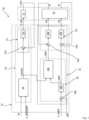
- Fig. 1 represents, partially, a block diagram of a first example of a regulation module according to the invention.
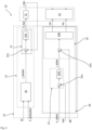
- Fig. 2 represents, partially, a block diagram of a second example of a regulation module according to the invention.
- a rotating electrical machine 10 in particular for a vehicle such as a motor vehicle or a drone, transforms mechanical energy into electrical energy, in alternator mode, and can operate in motor mode to transform electrical energy into mechanical energy.
- This rotating electrical machine 10 is, for example, an alternator, an alternator-starter, a reversible machine or an electric motor.
- the machine 10 may comprise a rotor 11, a stator 12 and an electronic assembly such as an inverter or a voltage converter.
- the housing may house the rotor 11 and the stator 12.
- the electronic assembly may be mounted on the housing or remote from the housing.
- the rotor 11 is a claw rotor comprising, here, two pole wheels and a coil wound around a core of the pole wheels.
- the machine has a commutator mounted on the rotor and has slip rings connected by wire connections to the coil and a brush holder arranged so that brushes rub on the slip rings to electrically power the rotor coil.
- the brushes of the brush holder are electrically connected to a control module of the electronic assembly which makes it possible to control the electrical power supply to the rotor.
- the stator 12 comprises a body, for example formed from a stack of sheets provided with notches, and an electrical winding mounted in the body.
- the electrical winding is formed from one or more phases comprising at least one electrical conductor.
- Each phase has an end forming a phase output which is electrically connected to a power module of the electronic assembly to enable control of the stator and rectification of the output current of the machine.
- the electronic assembly comprises a power stage, comprising at least one power module for receiving or supplying an electrical power signal to the electrical phases of the winding.
- the power module forms a voltage rectifier bridge to transform the voltage alternating current generated by the stator phases into a direct voltage and/or, conversely, to transform a direct voltage into an alternating voltage to supply the stator phases.
- the electronic assembly also includes a control stage comprising a control module making it possible in particular to control the rotor voltage 11 and the stator voltage 12 by interfacing with an external computer of the vehicle for the overall control of the machine.
- the optimization sub-module 16 of the rotor module 14 receives as input data a speed W and a machine power potential reference signal P_dcMaxRef.
- the machine power potential P_dcMaxRef is in particular the maximum power that the machine can generate for a given speed while respecting the steady-state constraints, in particular thermal constraints, of the machine.
- the optimization sub-module 16 generates a first intermediate setpoint I_RotRef from the speed W and the machine power potential reference signal P_dcMaxRef.
- the output parameters of the machine such as an output voltage Vdc, are not taken into account for the calculation of the first intermediate setpoint I_RotRef.
- the calculation of the first intermediate setpoint I_RotRef is for example made from a map giving an excitation current as a function of the speed W.
- the regulation sub-module 17 of the rotor module 14 receives as input data the first intermediate setpoint I_RotRef emitted by the optimization sub-module 16 and an excitation current I_Rot of the rotor 11.
- the regulation sub-module 17 comprises a comparator 17a for comparing the two input data to determine a first error.
- the regulation sub-module 17 also comprises here a corrector 17b for converting the first error into a first output quantity V_Rot to control the excitation current of the rotor coil 11.
- the excitation current I_Rot corresponds to the actual excitation current of the rotor 11.
- the excitation current I_Rot can be estimated or measured for example from a current sensor.
- the optimization sub-module 16 and the regulation sub-module 17 of the rotor module 14 operate at the same frequency which is for example 1kHZ.
- the rotor module 14 can use a regulation signal of the pulse width modulation type (called PWM).
- the rotor module 14 may have a thermal protection module (not shown) making it possible to prevent the rotor 11 from heating.
- the optimization sub-module 18 issues two different intermediate instructions here.
- the output current Idc corresponds to the actual output current of the machine 10 and in particular to the output of the electronic assembly after rectification via the power modules.
- the output current Idc can be estimated or measured for example from a current sensor.
- the present invention finds applications in particular in the field of regulation systems for alternators or reversible machines but it could also be applied to any type of rotating machine.
Landscapes
- Engineering & Computer Science (AREA)
- Power Engineering (AREA)
- Chemical & Material Sciences (AREA)
- Combustion & Propulsion (AREA)
- Mechanical Engineering (AREA)
- General Engineering & Computer Science (AREA)
- Transportation (AREA)
- Control Of Ac Motors In General (AREA)
- Control Of Motors That Do Not Use Commutators (AREA)
- Control Of Eletrric Generators (AREA)
Claims (8)
- Regelungsmodul für eine drehende elektrische Maschine eines Fahrzeugs, wobei die drehende elektrische Maschine (10) einen Rotor (11) und einen Stator (12) umfasst und wobei das Regelungsmodul (13) eine Betriebsart aufweist, in der die Maschine dazu bestimmt ist, von der Batterie des Fahrzeugs getrennt zu sein, wobei das Regelungsmodul (13) ein Rotormodul (14), das dazu ausgebildet ist, eine erste Ausgangsgröße (V_Rot) zur Steuerung des Rotors (12) auszugeben, und ein Statormodul (15, 20), das dazu ausgebildet ist, eine zweite Ausgangsgröße (Vq) und eine dritte Ausgangsgröße (Vd) zur Steuerung des Stators (12) auszugeben, aufweist, wobei das Regelungsmodul dadurch gekennzeichnet ist, dass:- das Rotormodul (14) dazu ausgebildet ist, einen ersten Zwischensollwert (I_RotRef) zu erzeugen, ausgehend von dem die erste Ausgangsgröße (V_Rot) erzeugt wird, wobei der erste Zwischensollwert (I_RotRef) ausgehend von einem Leistungspotential-Referenzsignal (Pdc_MaxRef) und einer Drehzahl (W) des Rotors bestimmt wird und unabhängig von einer Steuerleistung oder von einem Steuerdrehmoment der Maschine ist, das Leistungspotential der Maschine insbesondere die maximale Leistung ist, die die Maschine bei einer gegebenen Geschwindigkeit unter Berücksichtigung der, insbesondere thermischen, Einschränkungen im Dauerbetrieb der Maschine erzeugen kann,- das Statormodul (15, 20) dazu ausgebildet ist, einen zweiten Zwischensollwert (I_qRef, I_dcRef) zu erzeugen, ausgehend von dem die zweite Ausgangsgröße (Vq) und die dritte Ausgangsgröße (Vd) erzeugt werden, wobei der zweite Zwischensollwert (I_qRef, I_dcRef) ausgehend von der Ausgangsspannung (Vdc) der Maschine bestimmt wird.
- Regelungsmodul nach dem vorhergehenden Anspruch, dadurch gekennzeichnet, dass das Statormodul (15, 20) ein Optimierungsteilmodul (18, 21), das den zweiten Zwischensollwert (I_qRef, I_dcRef) erzeugt, und ein Regelungsteilmodul (19, 22), das die zweite Ausgangsgröße (Vd, Vq) erzeugt, beinhaltet, wobei das Optimierungsteilmodul und das Regelungsteilmodul insbesondere die gleiche Betriebsfrequenz aufweisen.
- Regelungsmodul nach einem der vorhergehenden Ansprüche, dadurch gekennzeichnet, dass der zweite Zwischensollwert (I_qRef, I_dcRef) ferner ausgehend von einer Referenzausgangsspannung (V_dcRef) bestimmt wird.
- Regelungsmodul nach einem der vorhergehenden Ansprüche, dadurch gekennzeichnet, dass die zweite Ausgangsgröße (Vq) ausgehend von einem Vergleich zwischen dem zweiten Zwischensollwert (I_qRef) und einem Quadraturachsenstrom (I_q) des Stators bestimmt wird.
- Regelungsmodul nach einem der vorhergehenden Ansprüche, dadurch gekennzeichnet, dass die dritte Ausgangsgröße (Vd) ausgehend von einem Vergleich zwischen einem dritten Zwischensollwert (I_dRef) und einem Direktachsenstrom (I_d) des Stators bestimmt wird.
- Regelungsmodul nach dem vorhergehenden Anspruch, dadurch gekennzeichnet, dass der dritte Zwischensollwert (I_dRef) ausgehend von dem ersten Zwischensollwert (I_RotRef) und von dem zweiten Zwischensollwert (I_qRef) bestimmt wird.
- Regelungsmodul nach einem der vorhergehenden Ansprüche, dadurch gekennzeichnet, dass das Rotormodul (14) ein Optimierungsteilmodul (16), das dazu ausgebildet ist den ersten Zwischensollwert (I_RotRef) zu erzeugen, und ein Regelungsteilmodul (17), das dazu ausgebildet ist, die erste Ausgangsgröße (V_Rot) zu erzeugen, umfasst, die erste Ausgangsgröße (V_Rot) ausgehend von einem Vergleich zwischen dem ersten Zwischensollwert (I_RotRef) und dem Erregungsstrom (I_Rot) des Rotors bestimmt wird.
- Drehende elektrische Maschine mit einem Regelungsmodul (13) nach einem der vorhergehenden Ansprüche.
Applications Claiming Priority (1)
| Application Number | Priority Date | Filing Date | Title |
|---|---|---|---|
| FR2101567A FR3119952B1 (fr) | 2021-02-18 | 2021-02-18 | Module de régulation pour une machine électrique tournante |
Publications (2)
| Publication Number | Publication Date |
|---|---|
| EP4047813A1 EP4047813A1 (de) | 2022-08-24 |
| EP4047813B1 true EP4047813B1 (de) | 2025-04-09 |
Family
ID=75539541
Family Applications (1)
| Application Number | Title | Priority Date | Filing Date |
|---|---|---|---|
| EP22154492.7A Active EP4047813B1 (de) | 2021-02-18 | 2022-02-01 | Regulierungsmodul für elektrisch umlaufende maschine |
Country Status (5)
| Country | Link |
|---|---|
| US (1) | US11855577B2 (de) |
| EP (1) | EP4047813B1 (de) |
| KR (1) | KR20220118344A (de) |
| CN (1) | CN115065282B (de) |
| FR (1) | FR3119952B1 (de) |
Family Cites Families (7)
| Publication number | Priority date | Publication date | Assignee | Title |
|---|---|---|---|---|
| WO2001067589A1 (en) * | 2000-03-09 | 2001-09-13 | Ecoair Corp. | Alternator system |
| DE10134883A1 (de) * | 2001-07-18 | 2003-01-30 | Abb Research Ltd | Verfahren und Vorrichtung zur drehzahlstellbaren leistungselektronischen Regelung einer getriebelosen Windkraftanlage |
| US7078876B2 (en) * | 2003-07-07 | 2006-07-18 | Pentadyne Power Corporation | Feedforward controller for synchronous reluctance machines |
| US7372174B2 (en) * | 2005-11-11 | 2008-05-13 | Converteam Ltd | Power converters |
| US10293243B1 (en) * | 2017-12-01 | 2019-05-21 | Future Motion, Inc. | Control system for electric vehicles |
| FR3083025B1 (fr) * | 2018-06-20 | 2020-07-10 | Valeo Equipements Electriques Moteur | Systeme de regulation ameliore pour une machine electrique tournante |
| US11394330B2 (en) * | 2019-07-31 | 2022-07-19 | GM Global Technology Operations LLC | Torque and current control methods for switching variable electric drive vehicles |
-
2021
- 2021-02-18 FR FR2101567A patent/FR3119952B1/fr active Active
-
2022
- 2022-02-01 EP EP22154492.7A patent/EP4047813B1/de active Active
- 2022-02-17 KR KR1020220020877A patent/KR20220118344A/ko active Pending
- 2022-02-18 US US17/651,638 patent/US11855577B2/en active Active
- 2022-02-18 CN CN202210163371.6A patent/CN115065282B/zh active Active
Also Published As
| Publication number | Publication date |
|---|---|
| KR20220118344A (ko) | 2022-08-25 |
| CN115065282A (zh) | 2022-09-16 |
| FR3119952B1 (fr) | 2023-01-13 |
| CN115065282B (zh) | 2026-02-06 |
| FR3119952A1 (fr) | 2022-08-19 |
| EP4047813A1 (de) | 2022-08-24 |
| US20220263442A1 (en) | 2022-08-18 |
| US11855577B2 (en) | 2023-12-26 |
Similar Documents
| Publication | Publication Date | Title |
|---|---|---|
| EP1632019B1 (de) | Steuergerät mit pulsbreitenmodulation für eine vielseitigeinsetzbare elektrische maschine und eine vielseitigeinsetzbare elektrische maschine ausgesttatet mit einem solchen steuergerät | |
| CA2480204C (fr) | Systeme de generation electrique a frequence fixe et procede de controle de celui-ci | |
| EP2676362A1 (de) | Anordnung mit betrieb in einer variablen abfolge | |
| EP3365970B1 (de) | Generatorstarter einer turbomaschine mit asynchroner elektrischer maschine mit mehreren windungen | |
| EP2686946B1 (de) | Elektrische energieversorgung eines flugzeugs | |
| EP2073371B1 (de) | Verfahren zur steuerung einer lichtmaschine eines kraftfahrzeugs | |
| EP2158672B1 (de) | Elektrische drehmaschine und verfahren zu ihrer steuerung | |
| EP4047813B1 (de) | Regulierungsmodul für elektrisch umlaufende maschine | |
| EP1112896B1 (de) | Leistungerzeugungsystem für ein Doppelspannungsnetz | |
| EP3166220A2 (de) | Vorrichtung zur dynamischen begrenzung, und verfahren zur dynamischen begrenzung durch eine solche vorrichtung | |
| EP3404822B1 (de) | Anlassereinheit eines motors, und anlassverfahren | |
| EP1430582B1 (de) | Temperaturbegrenzungsvorrichtung einer feldwicklung eines läufers einer rotierenden elektrischen maschine und batterielade vorrichtung mit dieser vorrichtung | |
| EP3095171A1 (de) | Verfahren zur steuerung eines elektronisches leistungsmoduls als synchroner gleichrichter, entsprechende steuerung vorrichtung und elektrische drehmaschine für ein elektrisches fahrzeug mit solch einer vorrichtung | |
| EP4113823A1 (de) | Spannungswandler für eine elektrisch umlaufende maschine | |
| EP4113822A1 (de) | Spannungswandler für eine elektrisch umlaufende maschine | |
| FR2990579A1 (fr) | Procede de pilotage d'un generateur d'un vehicule automobile | |
| WO2025003242A1 (fr) | Procede de controle d'une machine electrique en mode moteur par hybridation parallele d'un reseau electrique auxiliaire | |
| WO2019097158A1 (fr) | Machine electrique pour un vehicule automobile comprenant un capteur de courant | |
| WO2024256728A1 (fr) | Procede et dispositif de controle des puissances d'un reseau alternatif triphase par hybridation parallele avec un onduleur pilote et une source dc | |
| FR3075516A1 (fr) | Procede de pilotage d'une machine electrique tournante suite a une detection d'un appel de charge | |
| FR3128080A1 (fr) | Régulateur comprenant un module de sécurité pour une machine électrique tournante | |
| FR3024616A1 (fr) | Procede et dispositif de commande du couple electromagnetique d'un groupe motopropulseur | |
| FR2979769A1 (fr) | Machine electrique tournante | |
| FR3075517A1 (fr) | Procede de pilotage d'une machine electrique tournante |
Legal Events
| Date | Code | Title | Description |
|---|---|---|---|
| PUAI | Public reference made under article 153(3) epc to a published international application that has entered the european phase |
Free format text: ORIGINAL CODE: 0009012 |
|
| STAA | Information on the status of an ep patent application or granted ep patent |
Free format text: STATUS: REQUEST FOR EXAMINATION WAS MADE |
|
| 17P | Request for examination filed |
Effective date: 20220201 |
|
| AK | Designated contracting states |
Kind code of ref document: A1 Designated state(s): AL AT BE BG CH CY CZ DE DK EE ES FI FR GB GR HR HU IE IS IT LI LT LU LV MC MK MT NL NO PL PT RO RS SE SI SK SM TR |
|
| P01 | Opt-out of the competence of the unified patent court (upc) registered |
Effective date: 20230528 |
|
| STAA | Information on the status of an ep patent application or granted ep patent |
Free format text: STATUS: EXAMINATION IS IN PROGRESS |
|
| 17Q | First examination report despatched |
Effective date: 20231011 |
|
| GRAP | Despatch of communication of intention to grant a patent |
Free format text: ORIGINAL CODE: EPIDOSNIGR1 |
|
| STAA | Information on the status of an ep patent application or granted ep patent |
Free format text: STATUS: GRANT OF PATENT IS INTENDED |
|
| RIC1 | Information provided on ipc code assigned before grant |
Ipc: H02P 25/022 20160101ALN20240523BHEP Ipc: H02P 21/12 20160101ALI20240523BHEP Ipc: H02P 21/00 20160101ALI20240523BHEP Ipc: H02P 11/06 20060101ALI20240523BHEP Ipc: H02P 9/10 20060101ALI20240523BHEP Ipc: H02P 9/02 20060101AFI20240523BHEP |
|
| INTG | Intention to grant announced |
Effective date: 20240612 |
|
| RIC1 | Information provided on ipc code assigned before grant |
Ipc: H02P 25/022 20160101ALN20240604BHEP Ipc: H02P 21/12 20160101ALI20240604BHEP Ipc: H02P 21/00 20160101ALI20240604BHEP Ipc: H02P 11/06 20060101ALI20240604BHEP Ipc: H02P 9/10 20060101ALI20240604BHEP Ipc: H02P 9/02 20060101AFI20240604BHEP |
|
| RAP1 | Party data changed (applicant data changed or rights of an application transferred) |
Owner name: VALEO ELECTRIFICATION |
|
| GRAJ | Information related to disapproval of communication of intention to grant by the applicant or resumption of examination proceedings by the epo deleted |
Free format text: ORIGINAL CODE: EPIDOSDIGR1 |
|
| STAA | Information on the status of an ep patent application or granted ep patent |
Free format text: STATUS: EXAMINATION IS IN PROGRESS |
|
| GRAP | Despatch of communication of intention to grant a patent |
Free format text: ORIGINAL CODE: EPIDOSNIGR1 |
|
| STAA | Information on the status of an ep patent application or granted ep patent |
Free format text: STATUS: GRANT OF PATENT IS INTENDED |
|
| INTC | Intention to grant announced (deleted) | ||
| RIC1 | Information provided on ipc code assigned before grant |
Ipc: H02P 25/022 20160101ALN20241014BHEP Ipc: H02P 21/12 20160101ALI20241014BHEP Ipc: H02P 21/00 20160101ALI20241014BHEP Ipc: H02P 11/06 20060101ALI20241014BHEP Ipc: H02P 9/10 20060101ALI20241014BHEP Ipc: H02P 9/02 20060101AFI20241014BHEP |
|
| INTG | Intention to grant announced |
Effective date: 20241107 |
|
| GRAS | Grant fee paid |
Free format text: ORIGINAL CODE: EPIDOSNIGR3 |
|
| GRAA | (expected) grant |
Free format text: ORIGINAL CODE: 0009210 |
|
| STAA | Information on the status of an ep patent application or granted ep patent |
Free format text: STATUS: THE PATENT HAS BEEN GRANTED |
|
| AK | Designated contracting states |
Kind code of ref document: B1 Designated state(s): AL AT BE BG CH CY CZ DE DK EE ES FI FR GB GR HR HU IE IS IT LI LT LU LV MC MK MT NL NO PL PT RO RS SE SI SK SM TR |
|
| REG | Reference to a national code |
Ref country code: GB Ref legal event code: FG4D Free format text: NOT ENGLISH |
|
| REG | Reference to a national code |
Ref country code: CH Ref legal event code: EP |
|
| REG | Reference to a national code |
Ref country code: DE Ref legal event code: R096 Ref document number: 602022012741 Country of ref document: DE |
|
| REG | Reference to a national code |
Ref country code: IE Ref legal event code: FG4D Free format text: LANGUAGE OF EP DOCUMENT: FRENCH |
|
| REG | Reference to a national code |
Ref country code: NL Ref legal event code: MP Effective date: 20250409 |
|
| PG25 | Lapsed in a contracting state [announced via postgrant information from national office to epo] |
Ref country code: NL Free format text: LAPSE BECAUSE OF FAILURE TO SUBMIT A TRANSLATION OF THE DESCRIPTION OR TO PAY THE FEE WITHIN THE PRESCRIBED TIME-LIMIT Effective date: 20250409 |
|
| REG | Reference to a national code |
Ref country code: AT Ref legal event code: MK05 Ref document number: 1784464 Country of ref document: AT Kind code of ref document: T Effective date: 20250409 |
|
| PG25 | Lapsed in a contracting state [announced via postgrant information from national office to epo] |
Ref country code: FI Free format text: LAPSE BECAUSE OF FAILURE TO SUBMIT A TRANSLATION OF THE DESCRIPTION OR TO PAY THE FEE WITHIN THE PRESCRIBED TIME-LIMIT Effective date: 20250409 Ref country code: ES Free format text: LAPSE BECAUSE OF FAILURE TO SUBMIT A TRANSLATION OF THE DESCRIPTION OR TO PAY THE FEE WITHIN THE PRESCRIBED TIME-LIMIT Effective date: 20250409 Ref country code: PT Free format text: LAPSE BECAUSE OF FAILURE TO SUBMIT A TRANSLATION OF THE DESCRIPTION OR TO PAY THE FEE WITHIN THE PRESCRIBED TIME-LIMIT Effective date: 20250811 |
|
| REG | Reference to a national code |
Ref country code: LT Ref legal event code: MG9D |
|
| PG25 | Lapsed in a contracting state [announced via postgrant information from national office to epo] |
Ref country code: GR Free format text: LAPSE BECAUSE OF FAILURE TO SUBMIT A TRANSLATION OF THE DESCRIPTION OR TO PAY THE FEE WITHIN THE PRESCRIBED TIME-LIMIT Effective date: 20250710 Ref country code: NO Free format text: LAPSE BECAUSE OF FAILURE TO SUBMIT A TRANSLATION OF THE DESCRIPTION OR TO PAY THE FEE WITHIN THE PRESCRIBED TIME-LIMIT Effective date: 20250709 |
|
| PG25 | Lapsed in a contracting state [announced via postgrant information from national office to epo] |
Ref country code: PL Free format text: LAPSE BECAUSE OF FAILURE TO SUBMIT A TRANSLATION OF THE DESCRIPTION OR TO PAY THE FEE WITHIN THE PRESCRIBED TIME-LIMIT Effective date: 20250409 |
|
| PG25 | Lapsed in a contracting state [announced via postgrant information from national office to epo] |
Ref country code: BG Free format text: LAPSE BECAUSE OF FAILURE TO SUBMIT A TRANSLATION OF THE DESCRIPTION OR TO PAY THE FEE WITHIN THE PRESCRIBED TIME-LIMIT Effective date: 20250409 |
|
| PG25 | Lapsed in a contracting state [announced via postgrant information from national office to epo] |
Ref country code: HR Free format text: LAPSE BECAUSE OF FAILURE TO SUBMIT A TRANSLATION OF THE DESCRIPTION OR TO PAY THE FEE WITHIN THE PRESCRIBED TIME-LIMIT Effective date: 20250409 |
|
| PG25 | Lapsed in a contracting state [announced via postgrant information from national office to epo] |
Ref country code: AT Free format text: LAPSE BECAUSE OF FAILURE TO SUBMIT A TRANSLATION OF THE DESCRIPTION OR TO PAY THE FEE WITHIN THE PRESCRIBED TIME-LIMIT Effective date: 20250409 |
|
| PG25 | Lapsed in a contracting state [announced via postgrant information from national office to epo] |
Ref country code: RS Free format text: LAPSE BECAUSE OF FAILURE TO SUBMIT A TRANSLATION OF THE DESCRIPTION OR TO PAY THE FEE WITHIN THE PRESCRIBED TIME-LIMIT Effective date: 20250709 |
|
| PG25 | Lapsed in a contracting state [announced via postgrant information from national office to epo] |
Ref country code: IS Free format text: LAPSE BECAUSE OF FAILURE TO SUBMIT A TRANSLATION OF THE DESCRIPTION OR TO PAY THE FEE WITHIN THE PRESCRIBED TIME-LIMIT Effective date: 20250809 |
|
| PG25 | Lapsed in a contracting state [announced via postgrant information from national office to epo] |
Ref country code: LV Free format text: LAPSE BECAUSE OF FAILURE TO SUBMIT A TRANSLATION OF THE DESCRIPTION OR TO PAY THE FEE WITHIN THE PRESCRIBED TIME-LIMIT Effective date: 20250409 |
|
| REG | Reference to a national code |
Ref country code: DE Ref legal event code: R097 Ref document number: 602022012741 Country of ref document: DE |
|
| PG25 | Lapsed in a contracting state [announced via postgrant information from national office to epo] |
Ref country code: DK Free format text: LAPSE BECAUSE OF FAILURE TO SUBMIT A TRANSLATION OF THE DESCRIPTION OR TO PAY THE FEE WITHIN THE PRESCRIBED TIME-LIMIT Effective date: 20250409 Ref country code: SM Free format text: LAPSE BECAUSE OF FAILURE TO SUBMIT A TRANSLATION OF THE DESCRIPTION OR TO PAY THE FEE WITHIN THE PRESCRIBED TIME-LIMIT Effective date: 20250409 |
|
| PG25 | Lapsed in a contracting state [announced via postgrant information from national office to epo] |
Ref country code: CZ Free format text: LAPSE BECAUSE OF FAILURE TO SUBMIT A TRANSLATION OF THE DESCRIPTION OR TO PAY THE FEE WITHIN THE PRESCRIBED TIME-LIMIT Effective date: 20250409 |
|
| PG25 | Lapsed in a contracting state [announced via postgrant information from national office to epo] |
Ref country code: EE Free format text: LAPSE BECAUSE OF FAILURE TO SUBMIT A TRANSLATION OF THE DESCRIPTION OR TO PAY THE FEE WITHIN THE PRESCRIBED TIME-LIMIT Effective date: 20250409 |
|
| PG25 | Lapsed in a contracting state [announced via postgrant information from national office to epo] |
Ref country code: SK Free format text: LAPSE BECAUSE OF FAILURE TO SUBMIT A TRANSLATION OF THE DESCRIPTION OR TO PAY THE FEE WITHIN THE PRESCRIBED TIME-LIMIT Effective date: 20250409 |
|
| PG25 | Lapsed in a contracting state [announced via postgrant information from national office to epo] |
Ref country code: IT Free format text: LAPSE BECAUSE OF FAILURE TO SUBMIT A TRANSLATION OF THE DESCRIPTION OR TO PAY THE FEE WITHIN THE PRESCRIBED TIME-LIMIT Effective date: 20250409 |
|
| PLBE | No opposition filed within time limit |
Free format text: ORIGINAL CODE: 0009261 |
|
| STAA | Information on the status of an ep patent application or granted ep patent |
Free format text: STATUS: NO OPPOSITION FILED WITHIN TIME LIMIT |
|
| REG | Reference to a national code |
Ref country code: CH Ref legal event code: L10 Free format text: ST27 STATUS EVENT CODE: U-0-0-L10-L00 (AS PROVIDED BY THE NATIONAL OFFICE) Effective date: 20260218 |
|
| 26N | No opposition filed |
Effective date: 20260112 |
|
| PGFP | Annual fee paid to national office [announced via postgrant information from national office to epo] |
Ref country code: DE Payment date: 20260206 Year of fee payment: 5 |
|
| PGFP | Annual fee paid to national office [announced via postgrant information from national office to epo] |
Ref country code: FR Payment date: 20260227 Year of fee payment: 5 |