EP1430582B1 - Temperaturbegrenzungsvorrichtung einer feldwicklung eines läufers einer rotierenden elektrischen maschine und batterielade vorrichtung mit dieser vorrichtung - Google Patents
Temperaturbegrenzungsvorrichtung einer feldwicklung eines läufers einer rotierenden elektrischen maschine und batterielade vorrichtung mit dieser vorrichtung Download PDFInfo
- Publication number
- EP1430582B1 EP1430582B1 EP02800156.8A EP02800156A EP1430582B1 EP 1430582 B1 EP1430582 B1 EP 1430582B1 EP 02800156 A EP02800156 A EP 02800156A EP 1430582 B1 EP1430582 B1 EP 1430582B1
- Authority
- EP
- European Patent Office
- Prior art keywords
- excitation
- current
- excitation current
- rotor
- circuit
- Prior art date
- Legal status (The legal status is an assumption and is not a legal conclusion. Google has not performed a legal analysis and makes no representation as to the accuracy of the status listed.)
- Expired - Lifetime
Links
- 238000004804 winding Methods 0.000 title description 28
- 230000005284 excitation Effects 0.000 claims description 70
- 230000006698 induction Effects 0.000 claims 4
- 230000001276 controlling effect Effects 0.000 claims 2
- 230000001105 regulatory effect Effects 0.000 claims 2
- 238000013021 overheating Methods 0.000 description 5
- 239000000523 sample Substances 0.000 description 5
- 239000007858 starting material Substances 0.000 description 4
- 238000000034 method Methods 0.000 description 3
- 230000002441 reversible effect Effects 0.000 description 3
- 230000033228 biological regulation Effects 0.000 description 2
- 238000006243 chemical reaction Methods 0.000 description 2
- 238000001816 cooling Methods 0.000 description 2
- 239000012809 cooling fluid Substances 0.000 description 2
- 230000007423 decrease Effects 0.000 description 2
- 230000000694 effects Effects 0.000 description 2
- 238000005516 engineering process Methods 0.000 description 2
- 239000004065 semiconductor Substances 0.000 description 2
- RYGMFSIKBFXOCR-UHFFFAOYSA-N Copper Chemical compound [Cu] RYGMFSIKBFXOCR-UHFFFAOYSA-N 0.000 description 1
- 210000000078 claw Anatomy 0.000 description 1
- 238000002485 combustion reaction Methods 0.000 description 1
- 238000010276 construction Methods 0.000 description 1
- 229910052802 copper Inorganic materials 0.000 description 1
- 239000010949 copper Substances 0.000 description 1
- 238000010586 diagram Methods 0.000 description 1
- 238000009499 grossing Methods 0.000 description 1
- 238000010438 heat treatment Methods 0.000 description 1
- 210000000056 organ Anatomy 0.000 description 1
- 230000010287 polarization Effects 0.000 description 1
- 239000000758 substrate Substances 0.000 description 1
- 230000001360 synchronised effect Effects 0.000 description 1
Images


Classifications
-
- H—ELECTRICITY
- H02—GENERATION; CONVERSION OR DISTRIBUTION OF ELECTRIC POWER
- H02P—CONTROL OR REGULATION OF ELECTRIC MOTORS, ELECTRIC GENERATORS OR DYNAMO-ELECTRIC CONVERTERS; CONTROLLING TRANSFORMERS, REACTORS OR CHOKE COILS
- H02P9/00—Arrangements for controlling electric generators for the purpose of obtaining a desired output
- H02P9/14—Arrangements for controlling electric generators for the purpose of obtaining a desired output by variation of field
- H02P9/26—Arrangements for controlling electric generators for the purpose of obtaining a desired output by variation of field using discharge tubes or semiconductor devices
- H02P9/30—Arrangements for controlling electric generators for the purpose of obtaining a desired output by variation of field using discharge tubes or semiconductor devices using semiconductor devices
-
- H—ELECTRICITY
- H02—GENERATION; CONVERSION OR DISTRIBUTION OF ELECTRIC POWER
- H02H—EMERGENCY PROTECTIVE CIRCUIT ARRANGEMENTS
- H02H7/00—Emergency protective circuit arrangements specially adapted for specific types of electric machines or apparatus or for sectionalised protection of cable or line systems, and effecting automatic switching in the event of an undesired change from normal working conditions
- H02H7/06—Emergency protective circuit arrangements specially adapted for specific types of electric machines or apparatus or for sectionalised protection of cable or line systems, and effecting automatic switching in the event of an undesired change from normal working conditions for dynamo-electric generators; for synchronous capacitors
Definitions
- the invention relates to a device for controlling the temperature of the rotor inductor winding of a rotating electrical machine such as an alternator, in particular for a motor vehicle, of the type comprising means indicating the temperature of the rotor and means for regulation of the excitation current of the rotor as a function of the indicated temperature.
- the invention also relates to a device for charging a motor vehicle battery, comprising an alternator.
- thermal limiters are used to regulate, to protect the latter.
- a temperature sensor integrated in the voltage regulator is used to regulate the excitation current of the rotor.
- This solution uses an additional organ. Indeed, the temperature difference between the rotor and the regulator can vary greatly.
- a more accurate solution is to use thermal probes arranged outside the regulator. But this solution requires connections between the probe and the regulator and is therefore less economical than the thermal limiters inside the regulator. Plus, he is. difficult to place these thermal probes on the rotating assembly that is the rotor of an alternator.
- the present invention aims to propose a satisfactory solution to the problem that has just been stated.
- the regulator comprises means for reducing the excitation current when the value of the resistance is equal to or greater than a predetermined value.
- the temperature control device comprises a device for measuring the excitation current.
- the system according to the invention comprises means for calculating the average value of the excitation current.
- the regulator comprises means for measuring the negative peak value of the excitation current just after the closing of the excitation switch and the positive peak value of this current just before opening. of this switch and the calculating means is adapted to calculate the average value of the negative and positive peak values.
- the average value is established over several periods of the excitation signal.
- the device for charging the battery is characterized in that it comprises a control device according to the invention.
- the control system according to the invention will be described below in an application to a high-speed alternator which is part of a charging device.
- the battery for example of a motor vehicle and is equipped with a regulator of the battery voltage.
- a polyphase alternator for a motor vehicle comprises a pulley intended to be connected to the internal combustion engine of the vehicle and secured to the front end of a rotor shaft, a front bearing bearing a front ball bearing centrally. , a rear bearing centrally bearing a rear ball bearing, a stator comprising a grooved stator body carrying a stator winding, a rotor integral with the rotor shaft whose axial ends are mounted in the ball bearings respectively front and rear , a rectifying device for converting the alternating current produced by the stator winding into a direct current, a brush holder and a voltage regulator connected to the brushes of the brush holder.
- the cooling means comprise at least one internal fan secured to one of the axial ends of the rotor. This fan generates air circulation. To do this the adjacent landing is openwork.
- This winding comprises several windings namely at least one per phase that comprises the polyphase stator.
- front and rear bearings are shaped to form a chamber for the circulation of a cooling fluid, such as the cooling fluid of the engine of the vehicle.
- the rotor comprises two pole wheels between which is mounted a core carrying an inductor winding whose ends are connected to slip rings in contact with which come to rub the brushes of the brush holder carried by the rear bearing.
- the pole wheels being claw pole wheels with axially imbricated teeth.
- the rotor core may be independent of the pole wheels or consist of two half-cores.
- the rear bearing carries the straightening device and the regulator.
- the regulator and the rectifier are mounted outside the alternator.
- the system according to the invention is based on the discovery that the resistance of the inductor winding, also called excitation winding or rotor winding, of the rotor can serve as a criterion indicative of the temperature of the inductor winding and thus perform the function a thermal probe, with the advantage that this probe is not an additional member to be reported and placed on the hot parts of the alternator such as the rectifier bridge, the stator or in the regulator, as is known of the state of the art.
- the rotor inductor winding generators is generally made of copper whose resistance varies greatly with the temperature, which could be of the order of 70% between the temperatures of 25 ° C and 200 ° C.
- the value of this resistance becomes too great, it is deduced that the rotor is too hot and that it is necessary to reduce the excitation current of the inductor winding of the rotor to limit the flow and the heating of the alternator and of his rotor specifically.
- control circuit will first be described according to the figure 2 since this circuit makes it possible to measure the excitation current flowing through the excitation winding of the rotor and the knowledge of which is necessary for the implementation of the invention.
- the regulator circuit includes in its left part on the figure 2 , in a conventional manner per se, an FD winding constituting the excitation winding or rotor winding of a motor vehicle alternator or alternator-starter, a power transistor Tex, preferably in MOS technology, connected in series with the FD winding between the output voltage Ualt of the alternator (corresponding to the battery voltage) and the ground.
- a freewheeling diode is mounted in antiparallel with the FD winding.
- the current flowing in the transistor Tex is denoted Iex, while the current effectively flowing in the coil FD is noted Iexc. These two currents are respectively illustrated in solid lines and in broken lines on the figure 3 .
- the gate of the transistor Tex receives an excitation control signal Cex, consisting of a width-modulated signal. of impulse whose pace is also illustrated on the figure 3 .
- the current Iexc has a very low AC component.
- the current Iex is in turn chopped by the transistor Tex, and it is only at times when Tex is closed that the currents Iex and Iexc are superimposed.
- the device according to the invention comprises three main parts, namely a current measuring circuit 1 in the transistor Tex, a circuit 2 for storing the measured value, and an output circuit 3 capable of delivering signals representative of the current level. Iexc excitation.
- the circuit 1 firstly comprises a transistor Tm mounted in current mirror with the transistor Tex.
- This transistor TM has its drain connected to the drain of Tex and the voltage Ualt and its gate connected to the gate of Tex.
- the transistor Tm is therefore able to copy in a current Im, with a fixed fixed attenuation coefficient, the current Iex flowing between the drain and the source of Tex. For example, this coefficient is 1/1000.
- the transistor Tm is produced with the same basic cells as the power transistor Tex. In the example chosen here, it suffices to use to realize Tm a number of elementary cells of the transistor Tex.
- the proportional recopy of the current Tex in Tm implies that the three terminals of each transistor are respectively at the same potentials. It has been seen above that the drains and gates of the transistors are connected together. As regards source potentials, we observe on the figure 2 that the sources are connected together via the inverting and non-inverting inputs of an operational amplifier A1, which has the inherent property of keeping both of its inputs at the same potential. The condition of proportional copying is thus fulfilled.
- the source Tm is furthermore connected to the emitter of a bipolar transistor PNP T1, whose base is driven by the output of Al.
- the measuring circuit 1 furthermore comprises a resistor R1 connected between the collector of T1 and the earth. , and a resistor R2 and a Zener cleaving diode DZ1 both connected in series between the Tex source and the ground.
- the T1 collector is also connected to the non-inverting input of an operational amplifier A2, which by definition draws no current.
- the current I1 on the collector T1 is therefore equal to the current Im, the base current T1 that we will neglect here.
- This current produces across R1 a voltage U1 equal to R1xI1, and it is understood that this voltage U1 is in the form of a signal of the same waveform and level proportional to the current Iex in Tex.
- the resistor R2 and the clipping diode DZ1 (whose reverse voltage is preferably chosen to be 5 volts) generate on their common terminal a logic signal EN representative of the open or closed state of the transistor Tex.
- a logic signal EN representative of the open or closed state of the transistor Tex.
- the storage circuit 2 comprises in the first place a counter / downcounter circuit CD whose parallel outputs (for example on eight bits) are connected to the parallel inputs of a digital-to-analog converter CNA.
- the circuit 2 also comprises an input for clock signal CK (or alternatively an internal clock) which rates the counting and counting performed by the DC circuit.
- the operational amplifier A2 mounted as a comparator, receives on its non-inverting input as has been said the voltage U1, and on its inverting input the output voltage U2 of the converter CNA.
- the object of the comparator A2 is to generate a up / down count logic signal Up / Dn applied to the corresponding input of the up / down counter CD.
- the CNA circuit delivers a voltage U2 feedback which is maintained on a value that is closest to U1. But as soon as Tex becomes open, the The counter / down counter CD is stopped, so that U2 keeps as long as Tex is open the last acquired value before the opening of Tex.
- the voltage U2 can be directly used as an output of the circuit of the invention.
- a signal can be distorted by such disturbances, or by unexpected shift of the ground potential, which can occur in vehicles.
- the ohmic value of the resistor R1 can vary quite strongly, especially if it is carried out in monolithic technology.
- the device of the invention therefore advantageously comprises an output circuit 3.
- This circuit comprises a current generator built around an operational amplifier A3, an NPN bipolar transistor T2 and a resistor R3.
- the amplifier A3 receives on its non-inverting input the voltage U2 produced by the storage circuit 2, and its inverting input is connected to the emitter of T2.
- the output of A3 is connected to the T2 base.
- Resistor R3 is mounted between the T2 emitter and the ground.
- the circuit 3 also comprises a selector Com and a current mirror circuit built around MOS transistors T3 and T4, a bipolar transistor PNP T5, resistors R4 and R5 and a bipolar diode D1. More specifically, the movable contact of the selector Com is connected to the collector of T2, while one of its fixed contacts is connected to the cathode of D1 as well as to the base of T5. The anode of D1 is connected to the gate and the drain of T3, whose source is connected to the voltage Ualt via the resistor R4. On the other side of the current mirror, the transistor T5 has its source connected to the voltage Ualt via the resistor R5, its gate connected to the gate of T4 and its drain connected to the emitter of T5. The other fixed contact of the selector Com is connected to the collector of T5 and to a terminal of output Sim of the device.
- the operation of the output circuit 3 is as follows. In the first place, the current generating circuit A3, T2, R3 generates at the collector of T2 a current Is1 which is proportional to the voltage U2. In addition, if one chooses for R3 an ohmic value equal to that of R1, then the current Is1 is substantially equal to the current Im during the phases where Tex is closed.
- the current mirror T3, T4, T5, D1, R4, R5 is active to produce at the collector of T5, and thus on the output terminal Sim , an outgoing current Is2 which is proportional to Is1 or equal to it.
- junction voltage of the diode D1 located on the side of T3 makes it possible to ensure an identical polarization at the level of T3 and T4, since T4, for its part, has to undergo the emitter / base junction voltage. T5.
- resistors R4 and R5 are balancing resistors to maintain a good proportionality or equality between the currents Is1 and Is2.
- the selector Com makes it possible, by offering a "current out” output mode and an "incoming current” output mode, a greater flexibility of interfacing the device of the invention with an existing motor control device.
- the above device shows, as will be seen, good properties in terms of thermal compensation.
- the current Is1 or Is2 generated at the output has an excellent proportionality (or equality) with the current I1 itself proportional to the current in the transistor Tex.
- the device described above is advantageously made in the form of a monolithic circuit, and preferably on the same semiconductor chip as the excitation control circuit (including in particular the transistor Tex and the diode DL) of the alternator or alternator-starter.
- the transistors acting as current mirrors namely Tex and Tm on the one hand, and T3 and T4 on the other hand
- the resistors R1 and R3 are advantageously made on the one hand, and R4 and R5 on the other hand, so that they are exposed to the same thermal conditions.
- the circuit of the figure 2 is able to transmit a signal representative of the excitation current to the motor control device in the form of a current.
- the engine control device has an analog / digital conversion device capable of deriving from this current a numerical value that can be used in the processes that it performs.
- the circuit of the figure 2 may incorporate, downstream of the Sim terminal, such an analog / digital conversion circuit, the information being in this case transmitted to the engine control device in digital form, for example according to standard digital formats or protocols such as the "bit" synchronous "or the” LIN ".
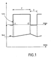
- FIG. 1 shows at the top the excitation signal Uex which is delivered by the excitation transistor Tex and characterized by its duty ratio ⁇ .
- the regulator in a manner known per se, measures and regulates the voltage of the Vreg edge network. As it was described above, the regulator is also able to measure the excitation current Iexc flowing through the inductor winding FD of the rotor of the alternator and whose typical pattern is given on the figure 3 . This Iexc excitation current is represented on the figure 1 below the excitation voltage Uex.
- the resistance of the inductor winding of the rotor is obtained by relating the values of the voltage of the edge network Vreg, the excitation duty cycle ⁇ and the excitation current Iexc.
- the excitation current Iexc is not rigorously constant and varies according to the alternations of the excitation signal Uex, which can disturb the calculation of the resistance of the Rrot rotor. Indeed, this current increases when the excitation transistor Tex is closed during the closing period F and decreases when the transistor is open during the period O.
- the regulator to measure the negative peak value of the excitation current Iexc just after the closing of the excitation transistor Tex, that is to say the value measured at time t1, and the value of positive peak of this current, measured just before the opening of the transistor Tex, that is to say at time t2, as shown in FIG. figure 1 .
- the average value of the excitation current is the average of the negative and positive peak values.
- the excitation duty cycle can vary greatly from one period to another. To take this variation into account, it is proposed to also average the cyclical report over several periods. This average is easily achievable with a digital controller. In some devices it is obtained automatically. For example if we use the solutions described in the French patent 2,747,860 of the applicant, the value of the duty cycle used for the closed loop can be considered as an average value of the excitation duty cycle for calculating the resistance of the rotor Rrot.
- the control system which has just been described as being particularly applicable to alternators or high-speed starter alternator for a motor vehicle is usable in all cases where a problem of overheating identical or similar to the problem that has been described arises.
- the method of controlling the temperature of the winding by Establishing the resistance of this winding is of course usable in charging devices of the battery for a motor vehicle.
- an alternator-starter is a reversible machine capable of operating as a current generator or an electric motor for, in particular, starting the vehicle.
Landscapes
- Engineering & Computer Science (AREA)
- Power Engineering (AREA)
- Control Of Eletrric Generators (AREA)
- Control Of Charge By Means Of Generators (AREA)
Claims (9)
- Vorrichtung zur Kontrolle der Temperatur der Feldwicklung des Rotors einer drehenden elektrischen Maschine, wie eines Drehstromgenerators, insbesondere für ein Kraftfahrzeug, von der Art, die Anzeigeeinrichtungen der Temperatur des Rotors und Regeleinrichtungen des Erregerstroms des Rotors abhängig von der angezeigten Temperatur enthält, dadurch gekennzeichnet, dass die Anzeigeeinrichtungen der Temperatur des Rotors vom Widerstand der Feldwicklung (FD) des Rotors geformt werden, dass sie Einrichtungen zur Erstellung des Werts des Widerstands der Feldwicklung ausgehend von mindestens drei Parametern aufweist, nämlich dem Taktverhältnis des Erregersignals, dem Wert des Erregerstroms und dem Wert der geregelten Spannung der Versorgungsquelle mit elektrischer Energie, und dass sie Einrichtungen zur Berechnung des Mittelwerts des Erregerstroms aufweist, und dass der Mittelwert des Erregerstroms ausgehend von den Werten von positiven und negativen Spitzen des Erregerstroms erstellt wird, die kurz nach dem Schließen des Erregerschalters des Durchflusses des Erregerstroms und kurz vor dem Öffnen des Schalters gemessen werden.
- Vorrichtung nach Anspruch 1, dadurch gekennzeichnet, dass sie Einrichtungen zur Reduzierung des Erregerstroms (Iexc) aufweist, wenn der Wert des Widerstands gleich einem oder höher als ein vorbestimmter Wert ist.
- Vorrichtung nach Anspruch 1 oder 2, dadurch gekennzeichnet, dass sie eine Vorrichtung zum Messen des Erregerstroms aufweist.
- Vorrichtung nach einem der vorhergehenden Ansprüche, dadurch gekennzeichnet, dass der Mittelwert des Erregerstroms über mehrere Perioden des Erregersignals erstellt wird.
- Vorrichtung nach einem der vorhergehenden Ansprüche, dadurch gekennzeichnet, dass sie eine Messvorrichtung des Erregerstroms (1), einen Speicherschaltkreis des gemessenen Werts (2) und einen Ausgangsschaltkreis (3) aufweist, der für den Pegel des Erregerstroms (Iexc) repräsentative Signale liefern kann.
- Vorrichtung nach Anspruch 5, dadurch gekennzeichnet, dass der Messschaltkreis des Erregerstroms einen Transistor (Tm) aufweist, der als Stromspiegel mit einem Leistungstransistor (Tex) montiert ist, der in Reihe mit der Feldwicklung (FD) geschaltet ist, und dass der Leistungstransistor (Tex) ein Erregungssteuersignal empfängt, das aus einem Signal mit Amplitudenbreitenmodulation besteht.
- Vorrichtung nach Anspruch 5 oder 6, dadurch gekennzeichnet, dass der Speicherschaltkreis (2) einen Vorwärts/Rückwärtszähler-Schaltkreis (CD) aufweist.
- Vorrichtung nach einem der Ansprüche 5 bis 7, dadurch gekennzeichnet, dass der Ausgangsschaltkreis (3) einen Stromgenerator, einen Wahlschalter (Com) und einen Stromspiegelschaltkreis aufweist.
- Ladevorrichtung der Batterie für ein Kraftfahrzeug, die einen Drehstromgenerator aufweist, dadurch gekennzeichnet, dass sie eine Kontrollvorrichtung nach einem der vorhergehenden Ansprüche, aufweist.
Applications Claiming Priority (3)
| Application Number | Priority Date | Filing Date | Title |
|---|---|---|---|
| FR0112537A FR2830380B1 (fr) | 2001-09-28 | 2001-09-28 | Dispositif de limitation de la temperature de l'enroulement inducteur du rotor d'une machine electrique tournante et dispositif de charge d'une batterie pourvu d'un tel dispositif de controle |
| FR0112537 | 2001-09-28 | ||
| PCT/FR2002/003303 WO2003030327A1 (fr) | 2001-09-28 | 2002-09-27 | Dispositif de limitation de la temperature de l'enroulement inducteur du rotor d'une machine electrique tournante et dispositif de charge d'une batterie pourvu d'un tel dispositif de controle |
Publications (2)
| Publication Number | Publication Date |
|---|---|
| EP1430582A1 EP1430582A1 (de) | 2004-06-23 |
| EP1430582B1 true EP1430582B1 (de) | 2013-05-08 |
Family
ID=8867740
Family Applications (1)
| Application Number | Title | Priority Date | Filing Date |
|---|---|---|---|
| EP02800156.8A Expired - Lifetime EP1430582B1 (de) | 2001-09-28 | 2002-09-27 | Temperaturbegrenzungsvorrichtung einer feldwicklung eines läufers einer rotierenden elektrischen maschine und batterielade vorrichtung mit dieser vorrichtung |
Country Status (6)
| Country | Link |
|---|---|
| EP (1) | EP1430582B1 (de) |
| JP (1) | JP4313673B2 (de) |
| KR (1) | KR100920264B1 (de) |
| ES (1) | ES2423410T3 (de) |
| FR (1) | FR2830380B1 (de) |
| WO (1) | WO2003030327A1 (de) |
Families Citing this family (2)
| Publication number | Priority date | Publication date | Assignee | Title |
|---|---|---|---|---|
| JP4736668B2 (ja) * | 2005-09-26 | 2011-07-27 | 株式会社デンソー | 負荷駆動装置の信号検出装置 |
| KR101454444B1 (ko) * | 2013-02-04 | 2014-10-28 | 타타대우상용차 주식회사 | 차량용 발전기를 이용한 차량의 발전 제어장치 및 제어방법 |
Family Cites Families (3)
| Publication number | Priority date | Publication date | Assignee | Title |
|---|---|---|---|---|
| US5510687A (en) * | 1994-04-29 | 1996-04-23 | Allen-Bradley Company, Inc. | Electric motor controller with temperature protection |
| FR2747860B1 (fr) * | 1996-04-18 | 1998-05-22 | Valeo Equip Electr Moteur | Procede de regulation par traitement numerique du courant d'excitation d'un alternateur de vehicule automobile et dispositif regulateur mettant en oeuvre un tel procede |
| US5708336A (en) * | 1996-08-21 | 1998-01-13 | Hughes Electronics | Thermal control system for a motor |
-
2001
- 2001-09-28 FR FR0112537A patent/FR2830380B1/fr not_active Expired - Fee Related
-
2002
- 2002-09-27 JP JP2003533408A patent/JP4313673B2/ja not_active Expired - Fee Related
- 2002-09-27 KR KR1020047004672A patent/KR100920264B1/ko active IP Right Grant
- 2002-09-27 WO PCT/FR2002/003303 patent/WO2003030327A1/fr active Application Filing
- 2002-09-27 ES ES02800156T patent/ES2423410T3/es not_active Expired - Lifetime
- 2002-09-27 EP EP02800156.8A patent/EP1430582B1/de not_active Expired - Lifetime
Also Published As
| Publication number | Publication date |
|---|---|
| KR100920264B1 (ko) | 2009-10-05 |
| WO2003030327A1 (fr) | 2003-04-10 |
| KR20040039456A (ko) | 2004-05-10 |
| JP4313673B2 (ja) | 2009-08-12 |
| ES2423410T3 (es) | 2013-09-20 |
| FR2830380B1 (fr) | 2005-01-07 |
| JP2005505222A (ja) | 2005-02-17 |
| FR2830380A1 (fr) | 2003-04-04 |
| EP1430582A1 (de) | 2004-06-23 |
Similar Documents
| Publication | Publication Date | Title |
|---|---|---|
| FR2864724A1 (fr) | Dispositif de commande destine a un dispositif de generateur electrique de vehicule a moteur | |
| FR2894735A1 (fr) | Generateur-moteur synchrone a enroulement de champ | |
| FR2855677A1 (fr) | Circuit de commande a modulation en largeur d'impulsions pour machine electrique multi mode et machine electrique multi mode equipee d'un tel circuit de commande | |
| EP3146626B1 (de) | Drehen elektrischer maschine für einen kraftfahrzeug | |
| WO2010049618A1 (fr) | Regulateur de tension d'alternateur equipe d'une interface programmable de traitement de signal | |
| WO2003088471A2 (fr) | Agencement pour la mise en œuvre d'une machine electrique tournante polyphasee et reversible associee a un moteur thermique d'un vehicule automobile | |
| WO2007083062A1 (fr) | Dispositif de pilotage d'une machine tournante polyphasee | |
| EP1847839B1 (de) | Verfahren zur Erkennung eines Widerstandskurzschlusses, System, Modul und Aufzeichnungsdatenträger für dieses Verfahren | |
| EP1943725B1 (de) | Messung eines von einer elektrischen drehmaschine wie ein generator gelieferten stroms | |
| FR2729256A1 (fr) | Methode et dispositif de controle d'un moteur synchrone monophase a aimants permanents apte a optimiser les parametres de fonctionnement meme en presence de fluctuations de la tension ou de la charge | |
| EP1430582B1 (de) | Temperaturbegrenzungsvorrichtung einer feldwicklung eines läufers einer rotierenden elektrischen maschine und batterielade vorrichtung mit dieser vorrichtung | |
| WO2009000996A2 (fr) | Machine electrique tournante et son procede de commande | |
| FR2821699A1 (fr) | Alternateur de vehicule automobile a sortie d'information d'excitation | |
| FR3077446A1 (fr) | Procede d'estimation d'un courant continu genere par une machine electrique tournante | |
| EP4047813A1 (de) | Regulierungsmodul für elektrisch umlaufende maschine | |
| FR2812982A1 (fr) | Alternateur pourvu de moyens perfectionnes d'interface entre un dispositif de controle moteur et son circuit regulateur, et interface correspondante | |
| FR3136129A1 (fr) | Dispositif d’alimentation d’un moteur synchrone à partir d’une source d’alimentation continue | |
| WO2022223756A1 (fr) | Convertisseur de tension comprenant un dispositif de protection | |
| WO2019097158A1 (fr) | Machine electrique pour un vehicule automobile comprenant un capteur de courant | |
| FR3082686A1 (fr) | Procede de protection thermique d'une machine electrique tournante | |
| FR3124909A1 (fr) | Convertisseur de tension pour une machine électrique tournante | |
| FR3075516A1 (fr) | Procede de pilotage d'une machine electrique tournante suite a une detection d'un appel de charge | |
| WO2019186020A1 (fr) | Procédé de commande d'un onduleur | |
| EP4113822A1 (de) | Spannungswandler für eine elektrisch umlaufende maschine | |
| FR3075517A1 (fr) | Procede de pilotage d'une machine electrique tournante |
Legal Events
| Date | Code | Title | Description |
|---|---|---|---|
| PUAI | Public reference made under article 153(3) epc to a published international application that has entered the european phase |
Free format text: ORIGINAL CODE: 0009012 |
|
| 17P | Request for examination filed |
Effective date: 20040413 |
|
| AK | Designated contracting states |
Kind code of ref document: A1 Designated state(s): AT BE BG CH CY CZ DE DK EE ES FI FR GB GR IE IT LI LU MC NL PT SE SK TR |
|
| 17Q | First examination report despatched |
Effective date: 20101215 |
|
| GRAP | Despatch of communication of intention to grant a patent |
Free format text: ORIGINAL CODE: EPIDOSNIGR1 |
|
| RIN1 | Information on inventor provided before grant (corrected) |
Inventor name: PIERRET, JEAN-MARIE |
|
| GRAS | Grant fee paid |
Free format text: ORIGINAL CODE: EPIDOSNIGR3 |
|
| GRAA | (expected) grant |
Free format text: ORIGINAL CODE: 0009210 |
|
| AK | Designated contracting states |
Kind code of ref document: B1 Designated state(s): AT BE BG CH CY CZ DE DK EE ES FI FR GB GR IE IT LI LU MC NL PT SE SK TR |
|
| REG | Reference to a national code |
Ref country code: GB Ref legal event code: FG4D Free format text: NOT ENGLISH |
|
| REG | Reference to a national code |
Ref country code: AT Ref legal event code: REF Ref document number: 611479 Country of ref document: AT Kind code of ref document: T Effective date: 20130515 Ref country code: CH Ref legal event code: EP |
|
| REG | Reference to a national code |
Ref country code: IE Ref legal event code: FG4D Free format text: LANGUAGE OF EP DOCUMENT: FRENCH |
|
| REG | Reference to a national code |
Ref country code: DE Ref legal event code: R096 Ref document number: 60244939 Country of ref document: DE Effective date: 20130704 |
|
| REG | Reference to a national code |
Ref country code: ES Ref legal event code: FG2A Ref document number: 2423410 Country of ref document: ES Kind code of ref document: T3 Effective date: 20130920 |
|
| REG | Reference to a national code |
Ref country code: AT Ref legal event code: MK05 Ref document number: 611479 Country of ref document: AT Kind code of ref document: T Effective date: 20130508 |
|
| REG | Reference to a national code |
Ref country code: NL Ref legal event code: VDEP Effective date: 20130508 |
|
| PG25 | Lapsed in a contracting state [announced via postgrant information from national office to epo] |
Ref country code: PT Free format text: LAPSE BECAUSE OF FAILURE TO SUBMIT A TRANSLATION OF THE DESCRIPTION OR TO PAY THE FEE WITHIN THE PRESCRIBED TIME-LIMIT Effective date: 20130909 Ref country code: FI Free format text: LAPSE BECAUSE OF FAILURE TO SUBMIT A TRANSLATION OF THE DESCRIPTION OR TO PAY THE FEE WITHIN THE PRESCRIBED TIME-LIMIT Effective date: 20130508 Ref country code: SE Free format text: LAPSE BECAUSE OF FAILURE TO SUBMIT A TRANSLATION OF THE DESCRIPTION OR TO PAY THE FEE WITHIN THE PRESCRIBED TIME-LIMIT Effective date: 20130508 Ref country code: AT Free format text: LAPSE BECAUSE OF FAILURE TO SUBMIT A TRANSLATION OF THE DESCRIPTION OR TO PAY THE FEE WITHIN THE PRESCRIBED TIME-LIMIT Effective date: 20130508 Ref country code: GR Free format text: LAPSE BECAUSE OF FAILURE TO SUBMIT A TRANSLATION OF THE DESCRIPTION OR TO PAY THE FEE WITHIN THE PRESCRIBED TIME-LIMIT Effective date: 20130809 |
|
| PG25 | Lapsed in a contracting state [announced via postgrant information from national office to epo] |
Ref country code: CY Free format text: LAPSE BECAUSE OF FAILURE TO SUBMIT A TRANSLATION OF THE DESCRIPTION OR TO PAY THE FEE WITHIN THE PRESCRIBED TIME-LIMIT Effective date: 20130508 Ref country code: BG Free format text: LAPSE BECAUSE OF FAILURE TO SUBMIT A TRANSLATION OF THE DESCRIPTION OR TO PAY THE FEE WITHIN THE PRESCRIBED TIME-LIMIT Effective date: 20130808 |
|
| PG25 | Lapsed in a contracting state [announced via postgrant information from national office to epo] |
Ref country code: DK Free format text: LAPSE BECAUSE OF FAILURE TO SUBMIT A TRANSLATION OF THE DESCRIPTION OR TO PAY THE FEE WITHIN THE PRESCRIBED TIME-LIMIT Effective date: 20130508 Ref country code: SK Free format text: LAPSE BECAUSE OF FAILURE TO SUBMIT A TRANSLATION OF THE DESCRIPTION OR TO PAY THE FEE WITHIN THE PRESCRIBED TIME-LIMIT Effective date: 20130508 Ref country code: EE Free format text: LAPSE BECAUSE OF FAILURE TO SUBMIT A TRANSLATION OF THE DESCRIPTION OR TO PAY THE FEE WITHIN THE PRESCRIBED TIME-LIMIT Effective date: 20130508 Ref country code: CZ Free format text: LAPSE BECAUSE OF FAILURE TO SUBMIT A TRANSLATION OF THE DESCRIPTION OR TO PAY THE FEE WITHIN THE PRESCRIBED TIME-LIMIT Effective date: 20130508 |
|
| PG25 | Lapsed in a contracting state [announced via postgrant information from national office to epo] |
Ref country code: NL Free format text: LAPSE BECAUSE OF FAILURE TO SUBMIT A TRANSLATION OF THE DESCRIPTION OR TO PAY THE FEE WITHIN THE PRESCRIBED TIME-LIMIT Effective date: 20130508 Ref country code: IT Free format text: LAPSE BECAUSE OF FAILURE TO SUBMIT A TRANSLATION OF THE DESCRIPTION OR TO PAY THE FEE WITHIN THE PRESCRIBED TIME-LIMIT Effective date: 20130508 |
|
| PLBE | No opposition filed within time limit |
Free format text: ORIGINAL CODE: 0009261 |
|
| STAA | Information on the status of an ep patent application or granted ep patent |
Free format text: STATUS: NO OPPOSITION FILED WITHIN TIME LIMIT |
|
| BERE | Be: lapsed |
Owner name: VALEO EQUIPEMENTS ELECTRIQUES MOTEUR Effective date: 20130930 |
|
| 26N | No opposition filed |
Effective date: 20140211 |
|
| PG25 | Lapsed in a contracting state [announced via postgrant information from national office to epo] |
Ref country code: MC Free format text: LAPSE BECAUSE OF FAILURE TO SUBMIT A TRANSLATION OF THE DESCRIPTION OR TO PAY THE FEE WITHIN THE PRESCRIBED TIME-LIMIT Effective date: 20130508 |
|
| REG | Reference to a national code |
Ref country code: CH Ref legal event code: PL |
|
| REG | Reference to a national code |
Ref country code: DE Ref legal event code: R097 Ref document number: 60244939 Country of ref document: DE Effective date: 20140211 |
|
| GBPC | Gb: european patent ceased through non-payment of renewal fee |
Effective date: 20130927 |
|
| REG | Reference to a national code |
Ref country code: IE Ref legal event code: MM4A |
|
| PG25 | Lapsed in a contracting state [announced via postgrant information from national office to epo] |
Ref country code: BE Free format text: LAPSE BECAUSE OF NON-PAYMENT OF DUE FEES Effective date: 20130930 Ref country code: GB Free format text: LAPSE BECAUSE OF NON-PAYMENT OF DUE FEES Effective date: 20130927 Ref country code: CH Free format text: LAPSE BECAUSE OF NON-PAYMENT OF DUE FEES Effective date: 20130930 Ref country code: IE Free format text: LAPSE BECAUSE OF NON-PAYMENT OF DUE FEES Effective date: 20130927 Ref country code: LI Free format text: LAPSE BECAUSE OF NON-PAYMENT OF DUE FEES Effective date: 20130930 |
|
| PG25 | Lapsed in a contracting state [announced via postgrant information from national office to epo] |
Ref country code: LU Free format text: LAPSE BECAUSE OF NON-PAYMENT OF DUE FEES Effective date: 20130927 |
|
| REG | Reference to a national code |
Ref country code: FR Ref legal event code: PLFP Year of fee payment: 15 |
|
| REG | Reference to a national code |
Ref country code: FR Ref legal event code: PLFP Year of fee payment: 16 |
|
| PGFP | Annual fee paid to national office [announced via postgrant information from national office to epo] |
Ref country code: TR Payment date: 20170918 Year of fee payment: 16 |
|
| REG | Reference to a national code |
Ref country code: FR Ref legal event code: PLFP Year of fee payment: 17 |
|
| PGFP | Annual fee paid to national office [announced via postgrant information from national office to epo] |
Ref country code: DE Payment date: 20190913 Year of fee payment: 18 Ref country code: FR Payment date: 20190930 Year of fee payment: 18 |
|
| PGFP | Annual fee paid to national office [announced via postgrant information from national office to epo] |
Ref country code: ES Payment date: 20191016 Year of fee payment: 18 |
|
| REG | Reference to a national code |
Ref country code: DE Ref legal event code: R119 Ref document number: 60244939 Country of ref document: DE |
|
| PG25 | Lapsed in a contracting state [announced via postgrant information from national office to epo] |
Ref country code: FR Free format text: LAPSE BECAUSE OF NON-PAYMENT OF DUE FEES Effective date: 20200930 Ref country code: DE Free format text: LAPSE BECAUSE OF NON-PAYMENT OF DUE FEES Effective date: 20210401 |
|
| REG | Reference to a national code |
Ref country code: ES Ref legal event code: FD2A Effective date: 20220118 |
|
| PG25 | Lapsed in a contracting state [announced via postgrant information from national office to epo] |
Ref country code: ES Free format text: LAPSE BECAUSE OF NON-PAYMENT OF DUE FEES Effective date: 20200928 |
|
| PG25 | Lapsed in a contracting state [announced via postgrant information from national office to epo] |
Ref country code: TR Free format text: LAPSE BECAUSE OF NON-PAYMENT OF DUE FEES Effective date: 20200927 |