EP1430582B1 - Device for limiting the temperature of the rotor field winding of a rotary electric machine and a device for charging a battery equipped with one such control device - Google Patents
Device for limiting the temperature of the rotor field winding of a rotary electric machine and a device for charging a battery equipped with one such control device Download PDFInfo
- Publication number
- EP1430582B1 EP1430582B1 EP02800156.8A EP02800156A EP1430582B1 EP 1430582 B1 EP1430582 B1 EP 1430582B1 EP 02800156 A EP02800156 A EP 02800156A EP 1430582 B1 EP1430582 B1 EP 1430582B1
- Authority
- EP
- European Patent Office
- Prior art keywords
- excitation
- current
- excitation current
- rotor
- circuit
- Prior art date
- Legal status (The legal status is an assumption and is not a legal conclusion. Google has not performed a legal analysis and makes no representation as to the accuracy of the status listed.)
- Expired - Lifetime
Links
- 238000004804 winding Methods 0.000 title description 28
- 230000005284 excitation Effects 0.000 claims description 70
- 230000006698 induction Effects 0.000 claims 4
- 230000001276 controlling effect Effects 0.000 claims 2
- 230000001105 regulatory effect Effects 0.000 claims 2
- 238000013021 overheating Methods 0.000 description 5
- 239000000523 sample Substances 0.000 description 5
- 239000007858 starting material Substances 0.000 description 4
- 238000000034 method Methods 0.000 description 3
- 230000002441 reversible effect Effects 0.000 description 3
- 230000033228 biological regulation Effects 0.000 description 2
- 238000006243 chemical reaction Methods 0.000 description 2
- 238000001816 cooling Methods 0.000 description 2
- 239000012809 cooling fluid Substances 0.000 description 2
- 230000007423 decrease Effects 0.000 description 2
- 230000000694 effects Effects 0.000 description 2
- 238000005516 engineering process Methods 0.000 description 2
- 239000004065 semiconductor Substances 0.000 description 2
- RYGMFSIKBFXOCR-UHFFFAOYSA-N Copper Chemical compound [Cu] RYGMFSIKBFXOCR-UHFFFAOYSA-N 0.000 description 1
- 210000000078 claw Anatomy 0.000 description 1
- 238000002485 combustion reaction Methods 0.000 description 1
- 238000010276 construction Methods 0.000 description 1
- 229910052802 copper Inorganic materials 0.000 description 1
- 239000010949 copper Substances 0.000 description 1
- 238000010586 diagram Methods 0.000 description 1
- 238000009499 grossing Methods 0.000 description 1
- 238000010438 heat treatment Methods 0.000 description 1
- 210000000056 organ Anatomy 0.000 description 1
- 230000010287 polarization Effects 0.000 description 1
- 239000000758 substrate Substances 0.000 description 1
- 230000001360 synchronised effect Effects 0.000 description 1
Images


Classifications
-
- H—ELECTRICITY
- H02—GENERATION; CONVERSION OR DISTRIBUTION OF ELECTRIC POWER
- H02P—CONTROL OR REGULATION OF ELECTRIC MOTORS, ELECTRIC GENERATORS OR DYNAMO-ELECTRIC CONVERTERS; CONTROLLING TRANSFORMERS, REACTORS OR CHOKE COILS
- H02P9/00—Arrangements for controlling electric generators for the purpose of obtaining a desired output
- H02P9/14—Arrangements for controlling electric generators for the purpose of obtaining a desired output by variation of field
- H02P9/26—Arrangements for controlling electric generators for the purpose of obtaining a desired output by variation of field using discharge tubes or semiconductor devices
- H02P9/30—Arrangements for controlling electric generators for the purpose of obtaining a desired output by variation of field using discharge tubes or semiconductor devices using semiconductor devices
-
- H—ELECTRICITY
- H02—GENERATION; CONVERSION OR DISTRIBUTION OF ELECTRIC POWER
- H02H—EMERGENCY PROTECTIVE CIRCUIT ARRANGEMENTS
- H02H7/00—Emergency protective circuit arrangements specially adapted for specific types of electric machines or apparatus or for sectionalised protection of cable or line systems, and effecting automatic switching in the event of an undesired change from normal working conditions
- H02H7/06—Emergency protective circuit arrangements specially adapted for specific types of electric machines or apparatus or for sectionalised protection of cable or line systems, and effecting automatic switching in the event of an undesired change from normal working conditions for dynamo-electric generators; for synchronous capacitors
Definitions
- the invention relates to a device for controlling the temperature of the rotor inductor winding of a rotating electrical machine such as an alternator, in particular for a motor vehicle, of the type comprising means indicating the temperature of the rotor and means for regulation of the excitation current of the rotor as a function of the indicated temperature.
- the invention also relates to a device for charging a motor vehicle battery, comprising an alternator.
- thermal limiters are used to regulate, to protect the latter.
- a temperature sensor integrated in the voltage regulator is used to regulate the excitation current of the rotor.
- This solution uses an additional organ. Indeed, the temperature difference between the rotor and the regulator can vary greatly.
- a more accurate solution is to use thermal probes arranged outside the regulator. But this solution requires connections between the probe and the regulator and is therefore less economical than the thermal limiters inside the regulator. Plus, he is. difficult to place these thermal probes on the rotating assembly that is the rotor of an alternator.
- the present invention aims to propose a satisfactory solution to the problem that has just been stated.
- the regulator comprises means for reducing the excitation current when the value of the resistance is equal to or greater than a predetermined value.
- the temperature control device comprises a device for measuring the excitation current.
- the system according to the invention comprises means for calculating the average value of the excitation current.
- the regulator comprises means for measuring the negative peak value of the excitation current just after the closing of the excitation switch and the positive peak value of this current just before opening. of this switch and the calculating means is adapted to calculate the average value of the negative and positive peak values.
- the average value is established over several periods of the excitation signal.
- the device for charging the battery is characterized in that it comprises a control device according to the invention.
- the control system according to the invention will be described below in an application to a high-speed alternator which is part of a charging device.
- the battery for example of a motor vehicle and is equipped with a regulator of the battery voltage.
- a polyphase alternator for a motor vehicle comprises a pulley intended to be connected to the internal combustion engine of the vehicle and secured to the front end of a rotor shaft, a front bearing bearing a front ball bearing centrally. , a rear bearing centrally bearing a rear ball bearing, a stator comprising a grooved stator body carrying a stator winding, a rotor integral with the rotor shaft whose axial ends are mounted in the ball bearings respectively front and rear , a rectifying device for converting the alternating current produced by the stator winding into a direct current, a brush holder and a voltage regulator connected to the brushes of the brush holder.
- the cooling means comprise at least one internal fan secured to one of the axial ends of the rotor. This fan generates air circulation. To do this the adjacent landing is openwork.
- This winding comprises several windings namely at least one per phase that comprises the polyphase stator.
- front and rear bearings are shaped to form a chamber for the circulation of a cooling fluid, such as the cooling fluid of the engine of the vehicle.
- the rotor comprises two pole wheels between which is mounted a core carrying an inductor winding whose ends are connected to slip rings in contact with which come to rub the brushes of the brush holder carried by the rear bearing.
- the pole wheels being claw pole wheels with axially imbricated teeth.
- the rotor core may be independent of the pole wheels or consist of two half-cores.
- the rear bearing carries the straightening device and the regulator.
- the regulator and the rectifier are mounted outside the alternator.
- the system according to the invention is based on the discovery that the resistance of the inductor winding, also called excitation winding or rotor winding, of the rotor can serve as a criterion indicative of the temperature of the inductor winding and thus perform the function a thermal probe, with the advantage that this probe is not an additional member to be reported and placed on the hot parts of the alternator such as the rectifier bridge, the stator or in the regulator, as is known of the state of the art.
- the rotor inductor winding generators is generally made of copper whose resistance varies greatly with the temperature, which could be of the order of 70% between the temperatures of 25 ° C and 200 ° C.
- the value of this resistance becomes too great, it is deduced that the rotor is too hot and that it is necessary to reduce the excitation current of the inductor winding of the rotor to limit the flow and the heating of the alternator and of his rotor specifically.
- control circuit will first be described according to the figure 2 since this circuit makes it possible to measure the excitation current flowing through the excitation winding of the rotor and the knowledge of which is necessary for the implementation of the invention.
- the regulator circuit includes in its left part on the figure 2 , in a conventional manner per se, an FD winding constituting the excitation winding or rotor winding of a motor vehicle alternator or alternator-starter, a power transistor Tex, preferably in MOS technology, connected in series with the FD winding between the output voltage Ualt of the alternator (corresponding to the battery voltage) and the ground.
- a freewheeling diode is mounted in antiparallel with the FD winding.
- the current flowing in the transistor Tex is denoted Iex, while the current effectively flowing in the coil FD is noted Iexc. These two currents are respectively illustrated in solid lines and in broken lines on the figure 3 .
- the gate of the transistor Tex receives an excitation control signal Cex, consisting of a width-modulated signal. of impulse whose pace is also illustrated on the figure 3 .
- the current Iexc has a very low AC component.
- the current Iex is in turn chopped by the transistor Tex, and it is only at times when Tex is closed that the currents Iex and Iexc are superimposed.
- the device according to the invention comprises three main parts, namely a current measuring circuit 1 in the transistor Tex, a circuit 2 for storing the measured value, and an output circuit 3 capable of delivering signals representative of the current level. Iexc excitation.
- the circuit 1 firstly comprises a transistor Tm mounted in current mirror with the transistor Tex.
- This transistor TM has its drain connected to the drain of Tex and the voltage Ualt and its gate connected to the gate of Tex.
- the transistor Tm is therefore able to copy in a current Im, with a fixed fixed attenuation coefficient, the current Iex flowing between the drain and the source of Tex. For example, this coefficient is 1/1000.
- the transistor Tm is produced with the same basic cells as the power transistor Tex. In the example chosen here, it suffices to use to realize Tm a number of elementary cells of the transistor Tex.
- the proportional recopy of the current Tex in Tm implies that the three terminals of each transistor are respectively at the same potentials. It has been seen above that the drains and gates of the transistors are connected together. As regards source potentials, we observe on the figure 2 that the sources are connected together via the inverting and non-inverting inputs of an operational amplifier A1, which has the inherent property of keeping both of its inputs at the same potential. The condition of proportional copying is thus fulfilled.
- the source Tm is furthermore connected to the emitter of a bipolar transistor PNP T1, whose base is driven by the output of Al.
- the measuring circuit 1 furthermore comprises a resistor R1 connected between the collector of T1 and the earth. , and a resistor R2 and a Zener cleaving diode DZ1 both connected in series between the Tex source and the ground.
- the T1 collector is also connected to the non-inverting input of an operational amplifier A2, which by definition draws no current.
- the current I1 on the collector T1 is therefore equal to the current Im, the base current T1 that we will neglect here.
- This current produces across R1 a voltage U1 equal to R1xI1, and it is understood that this voltage U1 is in the form of a signal of the same waveform and level proportional to the current Iex in Tex.
- the resistor R2 and the clipping diode DZ1 (whose reverse voltage is preferably chosen to be 5 volts) generate on their common terminal a logic signal EN representative of the open or closed state of the transistor Tex.
- a logic signal EN representative of the open or closed state of the transistor Tex.
- the storage circuit 2 comprises in the first place a counter / downcounter circuit CD whose parallel outputs (for example on eight bits) are connected to the parallel inputs of a digital-to-analog converter CNA.
- the circuit 2 also comprises an input for clock signal CK (or alternatively an internal clock) which rates the counting and counting performed by the DC circuit.
- the operational amplifier A2 mounted as a comparator, receives on its non-inverting input as has been said the voltage U1, and on its inverting input the output voltage U2 of the converter CNA.
- the object of the comparator A2 is to generate a up / down count logic signal Up / Dn applied to the corresponding input of the up / down counter CD.
- the CNA circuit delivers a voltage U2 feedback which is maintained on a value that is closest to U1. But as soon as Tex becomes open, the The counter / down counter CD is stopped, so that U2 keeps as long as Tex is open the last acquired value before the opening of Tex.
- the voltage U2 can be directly used as an output of the circuit of the invention.
- a signal can be distorted by such disturbances, or by unexpected shift of the ground potential, which can occur in vehicles.
- the ohmic value of the resistor R1 can vary quite strongly, especially if it is carried out in monolithic technology.
- the device of the invention therefore advantageously comprises an output circuit 3.
- This circuit comprises a current generator built around an operational amplifier A3, an NPN bipolar transistor T2 and a resistor R3.
- the amplifier A3 receives on its non-inverting input the voltage U2 produced by the storage circuit 2, and its inverting input is connected to the emitter of T2.
- the output of A3 is connected to the T2 base.
- Resistor R3 is mounted between the T2 emitter and the ground.
- the circuit 3 also comprises a selector Com and a current mirror circuit built around MOS transistors T3 and T4, a bipolar transistor PNP T5, resistors R4 and R5 and a bipolar diode D1. More specifically, the movable contact of the selector Com is connected to the collector of T2, while one of its fixed contacts is connected to the cathode of D1 as well as to the base of T5. The anode of D1 is connected to the gate and the drain of T3, whose source is connected to the voltage Ualt via the resistor R4. On the other side of the current mirror, the transistor T5 has its source connected to the voltage Ualt via the resistor R5, its gate connected to the gate of T4 and its drain connected to the emitter of T5. The other fixed contact of the selector Com is connected to the collector of T5 and to a terminal of output Sim of the device.
- the operation of the output circuit 3 is as follows. In the first place, the current generating circuit A3, T2, R3 generates at the collector of T2 a current Is1 which is proportional to the voltage U2. In addition, if one chooses for R3 an ohmic value equal to that of R1, then the current Is1 is substantially equal to the current Im during the phases where Tex is closed.
- the current mirror T3, T4, T5, D1, R4, R5 is active to produce at the collector of T5, and thus on the output terminal Sim , an outgoing current Is2 which is proportional to Is1 or equal to it.
- junction voltage of the diode D1 located on the side of T3 makes it possible to ensure an identical polarization at the level of T3 and T4, since T4, for its part, has to undergo the emitter / base junction voltage. T5.
- resistors R4 and R5 are balancing resistors to maintain a good proportionality or equality between the currents Is1 and Is2.
- the selector Com makes it possible, by offering a "current out” output mode and an "incoming current” output mode, a greater flexibility of interfacing the device of the invention with an existing motor control device.
- the above device shows, as will be seen, good properties in terms of thermal compensation.
- the current Is1 or Is2 generated at the output has an excellent proportionality (or equality) with the current I1 itself proportional to the current in the transistor Tex.
- the device described above is advantageously made in the form of a monolithic circuit, and preferably on the same semiconductor chip as the excitation control circuit (including in particular the transistor Tex and the diode DL) of the alternator or alternator-starter.
- the transistors acting as current mirrors namely Tex and Tm on the one hand, and T3 and T4 on the other hand
- the resistors R1 and R3 are advantageously made on the one hand, and R4 and R5 on the other hand, so that they are exposed to the same thermal conditions.
- the circuit of the figure 2 is able to transmit a signal representative of the excitation current to the motor control device in the form of a current.
- the engine control device has an analog / digital conversion device capable of deriving from this current a numerical value that can be used in the processes that it performs.
- the circuit of the figure 2 may incorporate, downstream of the Sim terminal, such an analog / digital conversion circuit, the information being in this case transmitted to the engine control device in digital form, for example according to standard digital formats or protocols such as the "bit" synchronous "or the” LIN ".
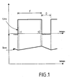
- FIG. 1 shows at the top the excitation signal Uex which is delivered by the excitation transistor Tex and characterized by its duty ratio ⁇ .
- the regulator in a manner known per se, measures and regulates the voltage of the Vreg edge network. As it was described above, the regulator is also able to measure the excitation current Iexc flowing through the inductor winding FD of the rotor of the alternator and whose typical pattern is given on the figure 3 . This Iexc excitation current is represented on the figure 1 below the excitation voltage Uex.
- the resistance of the inductor winding of the rotor is obtained by relating the values of the voltage of the edge network Vreg, the excitation duty cycle ⁇ and the excitation current Iexc.
- the excitation current Iexc is not rigorously constant and varies according to the alternations of the excitation signal Uex, which can disturb the calculation of the resistance of the Rrot rotor. Indeed, this current increases when the excitation transistor Tex is closed during the closing period F and decreases when the transistor is open during the period O.
- the regulator to measure the negative peak value of the excitation current Iexc just after the closing of the excitation transistor Tex, that is to say the value measured at time t1, and the value of positive peak of this current, measured just before the opening of the transistor Tex, that is to say at time t2, as shown in FIG. figure 1 .
- the average value of the excitation current is the average of the negative and positive peak values.
- the excitation duty cycle can vary greatly from one period to another. To take this variation into account, it is proposed to also average the cyclical report over several periods. This average is easily achievable with a digital controller. In some devices it is obtained automatically. For example if we use the solutions described in the French patent 2,747,860 of the applicant, the value of the duty cycle used for the closed loop can be considered as an average value of the excitation duty cycle for calculating the resistance of the rotor Rrot.
- the control system which has just been described as being particularly applicable to alternators or high-speed starter alternator for a motor vehicle is usable in all cases where a problem of overheating identical or similar to the problem that has been described arises.
- the method of controlling the temperature of the winding by Establishing the resistance of this winding is of course usable in charging devices of the battery for a motor vehicle.
- an alternator-starter is a reversible machine capable of operating as a current generator or an electric motor for, in particular, starting the vehicle.
Landscapes
- Engineering & Computer Science (AREA)
- Power Engineering (AREA)
- Control Of Eletrric Generators (AREA)
- Control Of Charge By Means Of Generators (AREA)
Description
L'invention concerne un dispositif de contrôle de la température de l'enroulement inducteur du rotor d'une machine électrique tournante tel qu'un alternateur, notamment pour véhicule automobile, du type comprenant des moyens indicateur de la température du rotor et des moyens de régulation du courant d'excitation du rotor en fonction de la température indiquée.The invention relates to a device for controlling the temperature of the rotor inductor winding of a rotating electrical machine such as an alternator, in particular for a motor vehicle, of the type comprising means indicating the temperature of the rotor and means for regulation of the excitation current of the rotor as a function of the indicated temperature.
L'invention concerne également un dispositif de charge d'une batterie de véhicule automobile, comportant un alternateur.The invention also relates to a device for charging a motor vehicle battery, comprising an alternator.
Dans les dispositifs de ce type, qui sont connus, pour réduire le courant d'excitation et le débit de l'alternateur en cas de surchauffe, on utilise des limiteurs thermiques internes au régulateur, pour protéger ce dernier. Dans le document
La présente invention a pour but de proposer une solution satisfaisante au problème qui vient d'être énoncé.The present invention aims to propose a satisfactory solution to the problem that has just been stated.
Ce but est résolu par la revendication 1This object is solved by
Selon une caractéristique de l'invention, le régulateur comprend des moyens de réduction du courant d'excitation lorsque la valeur de la résistance est égale ou supérieure à une valeur prédéterminée.According to a characteristic of the invention, the regulator comprises means for reducing the excitation current when the value of the resistance is equal to or greater than a predetermined value.
Selon une autre caractéristique de l'invention, le dispositif de contrôle de la température comporte un dispositif de mesure du courant d'excitation.According to another characteristic of the invention, the temperature control device comprises a device for measuring the excitation current.
Selon encore une autre caractéristique de l'invention, le système selon l'invention comporte des moyens pour calculer la valeur moyenne du courant d'excitation.According to yet another characteristic of the invention, the system according to the invention comprises means for calculating the average value of the excitation current.
Selon encore une caractéristique de l'invention, le régulateur comporte des moyens de mesure de la valeur de crête négative du courant d'excitation juste après la fermeture du commutateur d'excitation et la valeur de crête positive de ce courant juste avant l'ouverture de ce commutateur et le moyen de calcul est adapté pour calculer la valeur moyenne des valeurs de crêtes négatives et positives.According to another characteristic of the invention, the regulator comprises means for measuring the negative peak value of the excitation current just after the closing of the excitation switch and the positive peak value of this current just before opening. of this switch and the calculating means is adapted to calculate the average value of the negative and positive peak values.
Selon encore un autre caractéristique de l'invention, la valeur moyenne est établie sur plusieurs périodes du signal d'excitation.According to yet another characteristic of the invention, the average value is established over several periods of the excitation signal.
Le dispositif de charge de la batterie, notamment de véhicule automobile est caractérisé en ce qu'il comporte un dispositif de contrôle selon l'invention.The device for charging the battery, particularly a motor vehicle, is characterized in that it comprises a control device according to the invention.
L'invention sera mieux comprise, et d'autres buts, caractéristiques, détails et avantages de celle-ci apparaîtront plus clairement dans la description explicative qui va suivre faite en référence aux dessins schématiques annexés donnés uniquement à titre d'exemple illustrant un mode de réalisation de l'invention et dans lesquels :
- La
figure 1 illustre l'allure d'un signal de commande d'excitation et du courant d'excitation traversant le bobinage d'excitation du rotor d'un alternateur, pour expliciter le procédé d'établissement de la valeur moyenne du courant d'excitation, conformément à l'invention ; - La
figure 2 montre le schéma d'un circuit régulateur permettant la mesure du courant d'excitation traversant le bobinage d'excitation du rotor d'alternateur, et - La
figure 3 illustre les allures d'un signal de commande de l'excitation, du courant d'excitation, du courant traversant le commutateur de commande de l'excitation ainsi que deux de tensions intervenant dans le circuit de lafigure 2 .
- The
figure 1 illustrates the appearance of an excitation control signal and the excitation current flowing through the rotor excitation winding of an alternator, to explain the method for setting the average value of the excitation current, in accordance with to the invention; - The
figure 2 shows the diagram of a regulator circuit for measuring the excitation current flowing through the excitation coil of the alternator rotor, and - The
figure 3 illustrates the behavior of a control signal of the excitation, the excitation current, the current flowing through the control switch of the excitation as well as two voltages intervening in the circuit of thefigure 2 .
Le système de contrôle selon l'invention sera décrit ci-après dans une application à un alternateur à fort débit qui fait parti d'un dispositif de charge de la batterie par exemple d'un véhicule automobile et est équipé d'un régulateur de la tension de la batterie.The control system according to the invention will be described below in an application to a high-speed alternator which is part of a charging device. the battery for example of a motor vehicle and is equipped with a regulator of the battery voltage.
Ainsi qu'on le sait un alternateur polyphasé pour véhicule automobile comporte une poulie destinée à être reliée au moteur à combustion interne du véhicule et solidaire de l'extrémité avant d'un arbre de rotor, un palier avant portant centralement un roulement à billes avant, un palier arrière portant centralement un roulement à billes arrière, un stator comprenant un corps de stator rainuré portant un bobinage de stator, un rotor solidaire de l'arbre de rotor dont les extrémités axiales sont montées dans les roulements à billes respectivement avant et arrière, un dispositif de redressement pour transformer le courant alternatif produit par le bobinage du stator en un courant continu, un porte-balais et un régulateur de tension relié aux balais du porte-balais.As is known, a polyphase alternator for a motor vehicle comprises a pulley intended to be connected to the internal combustion engine of the vehicle and secured to the front end of a rotor shaft, a front bearing bearing a front ball bearing centrally. , a rear bearing centrally bearing a rear ball bearing, a stator comprising a grooved stator body carrying a stator winding, a rotor integral with the rotor shaft whose axial ends are mounted in the ball bearings respectively front and rear , a rectifying device for converting the alternating current produced by the stator winding into a direct current, a brush holder and a voltage regulator connected to the brushes of the brush holder.
Il est en outre prévu des moyens de refroidissement de l'alternateur.It is further provided means for cooling the alternator.
Dans une forme de réalisation les moyens de refroidissement comportent au moins un ventilateur interne solidaire de l'une des extrémités axiales du rotor. Ce ventilateur engendre une circulation d'air. Pour ce faire le palier adjacent est ajouré.In one embodiment, the cooling means comprise at least one internal fan secured to one of the axial ends of the rotor. This fan generates air circulation. To do this the adjacent landing is openwork.
Le plus souvent deux ventilateurs sont prévus à chaque extrémité axiale du rotor. Les ventilateurs sont implantés en dessous des extrémités du bobinage du stator formant des chignons de part et d'autre du corps du stator. Ce bobinage comporte plusieurs enroulement à savoir au moins un par phase que comporte le stator polyphasé.Most often two fans are provided at each axial end of the rotor. The fans are located below the ends of the stator winding forming buns on either side of the stator body. This winding comprises several windings namely at least one per phase that comprises the polyphase stator.
En variante les paliers avant et arrière sont conformés pour former une chambre pour la circulation d'un fluide de refroidissement, tel que le fluide de refroidissement du moteur thermique du véhicule.Alternatively the front and rear bearings are shaped to form a chamber for the circulation of a cooling fluid, such as the cooling fluid of the engine of the vehicle.
De manière connue, le rotor comporte deux roues polaires entre lesquelles est monté un noyau portant un enroulement inducteur dont les extrémités sont reliées à des bagues collectrices au contact desquels viennent frotter les balais du porte-balais porté par le palier arrière. Pour plus de précisions on se reportera par exemple au document
Le noyau du rotor peut être indépendant des roues polaires ou être constitué de deux demi noyaux.The rotor core may be independent of the pole wheels or consist of two half-cores.
Dans une forme de réalisation le palier arrière porte le dispositif de redressement et le régulateur.In one embodiment the rear bearing carries the straightening device and the regulator.
En variante comme décrit dans le document
Le circuit d'un tel régulateur est illustré sur la
Le système selon l'invention est basé sur la découverte que la résistance de l'enroulement inducteur, dit aussi bobinage d'excitation ou bobinage rotorique, du rotor peut servir de critère indicateur de la température de l'enroulement inducteur et donc accomplir la fonction d'une sonde thermique, avec l'avantage que cette sonde n'est pas un organe supplémentaire devant être rapporté et placé sur les parties chaudes de l'alternateur tel que le pont redresseur, le stator ou dans le régulateur, comme cela est connu de l'état de la technique.The system according to the invention is based on the discovery that the resistance of the inductor winding, also called excitation winding or rotor winding, of the rotor can serve as a criterion indicative of the temperature of the inductor winding and thus perform the function a thermal probe, with the advantage that this probe is not an additional member to be reported and placed on the hot parts of the alternator such as the rectifier bridge, the stator or in the regulator, as is known of the state of the art.
En effet, l'enroulement inducteur du rotor des alternateurs est réalisé généralement en cuivre dont la résistance varie fortement avec la température, qui pourrait être de l'ordre de 70 % entre les températures de 25°C et 200°C. Quand la valeur de cette résistance devient trop importante, on en déduit que le rotor est trop chaud et qu'il faut réduire le courant d'excitation de l'enroulement inducteur du rotor pour limiter le débit et l'échauffement de l'alternateur et de son rotor spécifiquement.Indeed, the rotor inductor winding generators is generally made of copper whose resistance varies greatly with the temperature, which could be of the order of 70% between the temperatures of 25 ° C and 200 ° C. When the value of this resistance becomes too great, it is deduced that the rotor is too hot and that it is necessary to reduce the excitation current of the inductor winding of the rotor to limit the flow and the heating of the alternator and of his rotor specifically.
Pour faciliter la compréhension de l'invention, on décrira tout d'abord le circuit régulateur selon la
Le circuit régulateur comprend dans sa partie gauche sur la
Le courant qui circule dans le transistor Tex est noté Iex, tandis que le courant qui circule effectivement dans le bobinage FD est noté Iexc. Ces deux courants, sont illustrés respectivement en traits pleins et en traits interrompus sur la
De façon également classique, la grille du transistor Tex reçoit un signal de commande d'excitation Cex, constitué d'un signal à modulation de largeur d'impulsion dont l'allure est également illustrée sur la
On observe sur la
Le dispositif selon l'invention comprend trois parties principales, à savoir un circuit 1 de mesure de courant dans le transistor Tex, un circuit 2 de mémorisation de la valeur mesurée, et un circuit de sortie 3 apte à délivrer des signaux représentatifs du niveau courant d'excitation Iexc.The device according to the invention comprises three main parts, namely a
Le circuit 1 comprend tout d'abord un transistor Tm monté en miroir de courant avec le transistor Tex. Ce transistor TM a son drain reliée au drain de Tex et à la tension Ualt et sa grille reliée à la grille de Tex.The
Le transistor Tm est donc capable de recopier en un courant Im, avec un coefficient d'atténuation fixe prédéterminée, le courant Iex circulant entre le drain et la source de Tex. Par exemple, ce coefficient est de 1/1000.The transistor Tm is therefore able to copy in a current Im, with a fixed fixed attenuation coefficient, the current Iex flowing between the drain and the source of Tex. For example, this coefficient is 1/1000.
Avantageusement, pour assurer une bonne proportionnalité entre les courants Iex et Im, le transistor Tm est réalisé avec les mêmes cellules de base que le transistor de puissance Tex. Dans l'exemple choisi ici, il suffit d'utiliser pour réaliser Tm un nombre de cellules élémentaires du transistor Tex.Advantageously, to ensure a good proportionality between the currents Iex and Im, the transistor Tm is produced with the same basic cells as the power transistor Tex. In the example chosen here, it suffices to use to realize Tm a number of elementary cells of the transistor Tex.
La recopie proportionnelle du courant Tex dans Tm implique que les trois bornes de chaque transistor soient respectivement aux mêmes potentiels. On a vu plus haut que les drains et les grilles des transistors sont reliées ensemble. Pour ce qui concerne les potentiels de sources, on observe sur la
La source Tm est en outre relié à l'émetteur d'un transistor bipolaire PNP T1, dont la base est attaquée par la sortie de Al. Le circuit de mesure 1 comprend en outre une résistance R1 reliée entre le collecteur de T1 et la masse, et une résistance R2 et une diode Zéner écrêteuse DZ1 montées toutes les deux en série entre la source de Tex et la masse. Le collecteur de T1 est également relié à l'entrée non-inverseuse d'un amplificateur opérationnel A2, qui par définition ne tire aucun courant.The source Tm is furthermore connected to the emitter of a bipolar transistor PNP T1, whose base is driven by the output of Al. The measuring
Le courant I1 sur le collecteur de T1 est donc égal au courant Im, au courant de base de T1 près que l'on négligera ici.The current I1 on the collector T1 is therefore equal to the current Im, the base current T1 that we will neglect here.
Ce courant produit aux bornes de R1 une tension U1 égale à R1xI1, et l'on comprend que cette tension U1 se présente sous la forme d'un signal de même forme d'onde et de niveau proportionnel au courant Iex dans Tex.This current produces across R1 a voltage U1 equal to R1xI1, and it is understood that this voltage U1 is in the form of a signal of the same waveform and level proportional to the current Iex in Tex.
La résistance R2 et la diode écrêteuse DZ1 (dont la tension en inverse est choisie de préférence égale à 5 volts) engendrent sur leur borne commune un signal logique EN représentatif de l'état ouvert ou fermé du transistor Tex. Ainsi, si Tex est fermé, un courant circule dans R2 et DZ1 et le signal EN est au niveau logique "1" ; si au contraire Tex est ouvert, un courant inverse circule dans DZ1 et R2 et le signal logique EN se situe à un faible niveau au-dessous du zéro volt de la masse, niveau correspondant à la tension de jonction de DZ1 soit typiquement -0,8 volt, qui constitue un niveau logique "0".The resistor R2 and the clipping diode DZ1 (whose reverse voltage is preferably chosen to be 5 volts) generate on their common terminal a logic signal EN representative of the open or closed state of the transistor Tex. Thus, if Tex is closed, a current flows in R2 and DZ1 and the signal EN is at logic level "1"; if on the contrary Tex is open, a reverse current flows in DZ1 and R2 and the logic signal EN is at a low level below the zero volt of the mass, level corresponding to the junction voltage of DZ1 is typically -0, 8 volts, which constitutes a logical level "0".
Le circuit de mémorisation 2 comprend en premier lieu un circuit compteur/décompteur CD dont les sorties parallèles (par exemple sur huit bits) sont reliées aux entrées parallèles d'un convertisseur numérique/analogique CNA. Le circuit 2 comprend également une entrée pour signal d'horloge CK (ou en variante une horloge interne) qui cadence le comptage et le décomptage réalisés par le circuit DC. L'amplificateur opérationnel A2, monté en comparateur, reçoit sur son entrée non-inverseuse comme on l'a dit la tension U1, et sur son entrée inverseuse la tension U2 de sortie du convertisseur CNA. Le comparateur A2 a pour objet d'engendrer un signal logique Up/Dn de sens de comptage/décomptage appliqué à l'entrée correspondante du compteur/décompteur CD.The
Le fonctionnement de ce circuit de mémorisation 2 est le suivant :
- si Tex est ouvert, le signal EN est au niveau logique "0" si bien que le compteur/décompteur CD est gelé ; la tension U2 reste donc à une valeur constante ;
- si maintenant Tex est fermé, le signal EN est au niveau logique "1" pour activer le comptage/décomptage dans CD ; il existe alors deux possibilités :
- * si U2 < U1, la sortie de A2 est au niveau logique "1", ce qui correspond à un comptage dans le circuit CD ; la valeur de U2 augmente donc pour se rapprocher de U1 ;
- * si au contraire U2 > U1, la sortie de A2 est au niveau logique "0", ce qui cause un décomptage dans le circuit CD : la valeur de U2 diminue donc pour se rapprocher de U1.
- if Tex is open, the signal EN is at logic level "0" so that the up / down counter CD is frozen; the voltage U2 therefore remains at a constant value;
- if now Tex is closed, the signal EN is at logic level "1" to enable counting / downcounting in CD; there are two possibilities:
- if U2 <U1, the output of A2 is at logic level "1", which corresponds to a count in the circuit CD; the value of U2 therefore increases to approach U1;
- * if on the contrary U2> U1, the output of A2 is at logic level "0", which causes a countdown in the circuit CD: the value of U2 thus decreases to approach U1.
Ainsi l'on comprend que, dès que Tex est fermé, le circuit CNA délivre une tension U2 qui par rétroaction est maintenue sur une valeur qui est la plus proche de U1. Mais dès que Tex devient ouvert, le compteur/décompteur CD est arrêté, si bien que U2 conserve aussi longtemps que Tex est ouvert la dernière valeur acquise avant l'ouverture de Tex.Thus it is understood that, as soon as Tex is closed, the CNA circuit delivers a voltage U2 feedback which is maintained on a value that is closest to U1. But as soon as Tex becomes open, the The counter / down counter CD is stopped, so that U2 keeps as long as Tex is open the last acquired value before the opening of Tex.
L'allure de l'évolution de la tension U2 (en traits pleins) est illustrée sur la
On observera ici que la tension U2 peut être directement utilisée comme sortie du circuit de l'invention. Toutefois, dans le cas d'un environnement exposé à des perturbation électromagnétiques, un tel signal peut être faussé par de telles perturbations, ou encore par décalage inopiné du potentiel de masse, qui peut se produire dans les véhicules.It will be observed here that the voltage U2 can be directly used as an output of the circuit of the invention. However, in the case of an environment exposed to electromagnetic disturbances, such a signal can be distorted by such disturbances, or by unexpected shift of the ground potential, which can occur in vehicles.
En outre, la valeur ohmique de la résistance R1 peut varier assez fortement, en particulier si elle est réalisée en technologie monolithique.In addition, the ohmic value of the resistor R1 can vary quite strongly, especially if it is carried out in monolithic technology.
Le dispositif de l'invention comprend donc avantageusement un circuit de sortie 3. Ce circuit comprend un générateur de courant construit autour d'un amplificateur opérationnel A3, d'un transistor bipolaire NPN T2 et d'une résistance R3. L'amplificateur A3 reçoit sur son entrée non-inverseuse la tension U2 produite par le circuit de mémorisation 2, et son entrée inverseuse est reliée à l'émetteur de T2. La sortie de A3 est quant à elle reliée à la base de T2. La résistance R3 est montée entre l'émetteur de T2 et la masse.The device of the invention therefore advantageously comprises an
Le circuit 3 comprend également un sélecteur Com et un circuit à miroir de courant construit autour de transistors MOS T3 et T4, d'un transistor bipolaire PNP T5, de résistances R4 et R5 et d'une diode bipolaire D1. Plus précisément, le contact mobile du sélecteur Com est relié au collecteur de T2, tandis que l'un de ses contacts fixes est relié à la cathode de D1 ainsi qu'à la base de T5. L'anode de D1 est reliée à la grille et au drain de T3, dont la source est reliée à la tension Ualt via la résistance R4. De l'autre côté du miroir de courant, le transistor T5 a sa source reliée à la tension Ualt via la résistance R5, sa grille reliée à la grille de T4 et son drain relié à l'émetteur de T5. L'autre contact fixe du sélecteur Com est relié au collecteur de T5 ainsi qu'à une borne de sortie Sim du dispositif.The
Le fonctionnement du circuit de sortie 3 est le suivant. En premier lieu, le circuit générateur de courant A3, T2, R3 engendre au niveau du collecteur de T2 un courant Is1 qui est proportionnel à la tension U2. En outre, si l'on choisit pour R3 une valeur ohmique égale à celle de R1, alors le courant Is1 est sensiblement égal au courant Im pendant les phases où Tex est fermé.The operation of the
Lorsque le circuit Com a son contact mobile dans la position illustrée en traits pleins, le miroir de courant T3, T4, T5, D1, R4, R5 est actif pour produire au niveau du collecteur de T5, et donc sur la borne de sortie Sim, un courant sortant Is2 qui est proportionnel à Is1 ou égal à celui-ci.When the circuit Com has its moving contact in the position shown in solid lines, the current mirror T3, T4, T5, D1, R4, R5 is active to produce at the collector of T5, and thus on the output terminal Sim , an outgoing current Is2 which is proportional to Is1 or equal to it.
On notera ici que la tension de jonction de la diode D1 située du côté de T3 permet d'assurer une polarisation identique au niveau de T3 et de T4, étant donné que T4 a de son côté à subir la tension de jonction émetteur/base de T5.It will be noted here that the junction voltage of the diode D1 located on the side of T3 makes it possible to ensure an identical polarization at the level of T3 and T4, since T4, for its part, has to undergo the emitter / base junction voltage. T5.
On notera également que les résistances R4 et R5 sont des résistances d'équilibrage permettant de conserver une bonne proportionnalité ou égalité entre les courants Is1 et Is2.Note also that the resistors R4 and R5 are balancing resistors to maintain a good proportionality or equality between the currents Is1 and Is2.
A l'inverse, dans le cas où le sélecteur Com occupe la position indiquée en pointillés, c'est le courant Is2 qui est appliqué directement comme courant entrant sur la borne sortie Sim.Conversely, in the case where the selector Com occupies the position indicated in dashed lines, this is the Is2 current which is applied directly as incoming current to the Sim output terminal.
Ainsi le sélecteur Com permet, en offrant un mode de sortie "courant sortant" et un mode de sortie "courant entrant", une plus grande souplesse d'interfaçage du dispositif de l'invention avec un dispositif de contrôle moteur existant.Thus, the selector Com makes it possible, by offering a "current out" output mode and an "incoming current" output mode, a greater flexibility of interfacing the device of the invention with an existing motor control device.
Le dispositif ci-dessus présente comme on va le voir de bonnes propriétés en matière de compensation thermique. En particulier, le courant Is1 ou Is2 engendré en sortie présente une excellente proportionnalité (ou égalité) avec le courant I1 lui-même proportionnel au courant dans le transistor Tex.The above device shows, as will be seen, good properties in terms of thermal compensation. In particular, the current Is1 or Is2 generated at the output has an excellent proportionality (or equality) with the current I1 itself proportional to the current in the transistor Tex.
Plus précisément, on comprend que pendant les phases où Tex est passant, on a par construction : ![]()
![]()
On a également : ![]()
et ![]()
![]()
and ![]()
Si le rapport R1/R3 est constant, alors la proportionnalité entre I1 et Is1 est garantie.If the ratio R1 / R3 is constant, then the proportionality between I1 and Is1 is guaranteed.
En outre, si l'on choisit R1 = R3, alors on a : ![]()
![]()
Pour ce qui concerne maintenant la proportionnalité entre Im (sensiblement égal à I1) et Iex, elle est garantie lorsque les transistors Tex et Tm sont polarisés de la même façon et réalisés avec les mêmes cellules élémentaires sur un substrat semi-conducteur commun.As regards now the proportionality between Im (substantially equal to I1) and Iex, it is guaranteed when the transistors Tex and Tm are polarized in the same way and made with the same elementary cells on a common semiconductor substrate.
Enfin la proportionnalité ou l'égalité entre les valeurs de Is1 et Is2 est garantie par le recours à des transistors T3 et T4 polarisés identiquement et à des résistances proportionnelles ou identiques, respectivement.Finally the proportionality or the equality between the values of Is1 and Is2 is guaranteed by the use of transistors T3 and T4 polarized identically and with proportional or identical resistances, respectively.
Comme on l'a indiqué, le dispositif décrit ci-dessus est avantageusement réalisé sous forme d'un circuit monolithique, et de préférence sur la même puce de semi-conducteur que le circuit régulateur d'excitation (comportant en particulier le transistor Tex et la diode DL) de l'alternateur ou alterno-démarreur. Dans ce cas, on réalise avantageusement les transistors jouant le rôle de miroirs de courant (à savoir Tex et Tm d'une part, et T3 et T4 d'autre part) à partir des mêmes cellules élémentaires. En outre, on réalise avantageusement les résistances R1 et R3 d'une part, et R4 et R5 d'autre part, pour qu'elles soient exposées aux mêmes conditions thermiques.As indicated, the device described above is advantageously made in the form of a monolithic circuit, and preferably on the same semiconductor chip as the excitation control circuit (including in particular the transistor Tex and the diode DL) of the alternator or alternator-starter. In this case, the transistors acting as current mirrors (namely Tex and Tm on the one hand, and T3 and T4 on the other hand) are advantageously made from the same elementary cells. In addition, the resistors R1 and R3 are advantageously made on the one hand, and R4 and R5 on the other hand, so that they are exposed to the same thermal conditions.
Comme on l'a décrit, le circuit de la
En variante, le circuit de la
En se reportant à la
La résistance de l'enroulement inducteur du rotor s'obtient par mise en relation des valeurs de la tension du réseau de bord Vreg, du rapport cyclique d'excitation τ et du courant d'excitation Iexc.The resistance of the inductor winding of the rotor is obtained by relating the values of the voltage of the edge network Vreg, the excitation duty cycle τ and the excitation current Iexc.
En effet, si on néglige la chute de tension dans le transistor d'excitation Tex, dans les balais et dans la diode de roue libre, la tension moyenne Urot appliquée au rotor est pratiquement égale à : ![]()
![]()
Cette relation s'avère bien juste pour les cas de surchauffe lorsque les rapports cycliques d'excitation sont importants et l'effet de la diode de roue libre est faible. La valeur de la résistance du rotor Rrot s'obtient alors par l'équation suivante : ![]()
![]()
Le régulateur notamment lorsqu'il comporte une architecture numérique avec micro-processeur peut réaliser ce calcul. On peut considérer que la tension du réseau de bord Vreg varie peu car cette valeur ne dépend que de la compensation thermique acceptable pour la charge de la batterie. Dans ces conditions, la tension du réseau de bord peut être assimilée à une constante K, et la valeur de la résistance du rotor peut être calculée en appliquant l'équation suivante : ![]()
![]()
Or, comme le montre la
Or, pour assurer un bon niveau de régulation, le rapport cyclique d'excitation peut varier fortement d'une période à l'autre. Pour prendre en compte cette variation, il est proposé de faire aussi la moyenne du rapport cyclique sur plusieurs périodes. Cette moyenne est facilement réalisable avec un régulateur numérique. Dans certains dispositifs elle est obtenue automatiquement. Par exemple si l'on utilise les solutions décrites dans le brevet français
Le système de contrôle qui vient d'être décrit comme étant particulièrement applicable à des alternateurs ou alterno-démarreur à fort débit pour véhicule automobile est utilisable dans tous les cas où un problème de surchauffe identique ou similaire au problème qui a été décrit se pose. La méthode de contrôle de la température de l'enroulement par établissement de la résistance de cette enroulement est bien entendu utilisable dans des dispositifs de charge de la batterie pour véhicule automobile.The control system which has just been described as being particularly applicable to alternators or high-speed starter alternator for a motor vehicle is usable in all cases where a problem of overheating identical or similar to the problem that has been described arises. The method of controlling the temperature of the winding by Establishing the resistance of this winding is of course usable in charging devices of the battery for a motor vehicle.
Pour mémoire on rappellera qu'un alterno-démarreur est une machine réversible apte à fonctionner en générateur de courant ou en moteur électrique pour notamment démarrer le véhicule.For the record, it will be recalled that an alternator-starter is a reversible machine capable of operating as a current generator or an electric motor for, in particular, starting the vehicle.
Pour plus de précisions on se reportera au document
Claims (9)
- Device for controlling the temperature of the induction coil of the rotor of an electrical rotating machine such as an alternator, notably for a motor vehicle, of the type comprising means for indicating the temperature of the rotor and means for regulating the excitation current of the rotor as a function of the indicated temperature, characterized in that the means for indicating the temperature of the rotor are formed by the resistance of the induction coil (FD) of the rotor, in that it comprises means for establishing the value of the resistance of the induction coil based on at least three parameters, namely the duty cycle of the excitation signal, the value of the excitation current and the value of the regulated voltage of the electrical energy supply source, in that it comprises means for computing the mean value of the excitation current and in that the mean value of the excitation current is established on the basis of the positive and negative peak values of the excitation current, measured just after the closure of the excitation commutator for the passage of the excitation current and just before the opening of the commutator.
- Device according to Claim 1, characterized in that it comprises means for reducing the excitation current (Iexc) when the value of the resistance is equal to or greater than a predetermined value.
- Device according to Claim 1 or 2, characterized in that it comprises a device for measuring the excitation current.
- Device according to any one of the preceding claims, characterized in that the mean value of the excitation current is established over several periods of the excitation signal.
- Device according to any one of the preceding claims, characterized in that it comprises a device for measuring the excitation current (1), a circuit for storing the measured value (2) and an output circuit (3) capable of delivering signals representative of the level of the excitation current (Iexc).
- Device according to Claim 5, characterized in that the circuit for measuring the excitation current comprises a transistor (Tm) mounted as a current mirror with a power transistor (Tex) connected in series with the induction coil (FD) and in that the power transistor (Tex) receives an excitation control signal consisting of an amplitude-width modulation signal.
- Device according to Claim 5 or 6, characterized in that the storage circuit (2) comprises an up-down counter circuit (CD).
- Device according to any one of Claims 5 to 7, characterized in that the output circuit (3) comprises a current generator, a selector (Com) and a current mirror circuit.
- Battery charging device for a motor vehicle comprising an alternator, characterized in that it comprises a controlling device according to any one of the preceding claims.
Applications Claiming Priority (3)
| Application Number | Priority Date | Filing Date | Title |
|---|---|---|---|
| FR0112537A FR2830380B1 (en) | 2001-09-28 | 2001-09-28 | DEVICE FOR LIMITING THE TEMPERATURE OF THE ROTOR-INDUCING WINDING OF A ROTATING ELECTRIC MACHINE AND DEVICE FOR CHARGING A BATTERY WITH SUCH A CONTROL DEVICE |
| FR0112537 | 2001-09-28 | ||
| PCT/FR2002/003303 WO2003030327A1 (en) | 2001-09-28 | 2002-09-27 | Device for limiting the temperature of the rotor field winding of a rotary electric machine and a device for charging a battery equipped with one such control device |
Publications (2)
| Publication Number | Publication Date |
|---|---|
| EP1430582A1 EP1430582A1 (en) | 2004-06-23 |
| EP1430582B1 true EP1430582B1 (en) | 2013-05-08 |
Family
ID=8867740
Family Applications (1)
| Application Number | Title | Priority Date | Filing Date |
|---|---|---|---|
| EP02800156.8A Expired - Lifetime EP1430582B1 (en) | 2001-09-28 | 2002-09-27 | Device for limiting the temperature of the rotor field winding of a rotary electric machine and a device for charging a battery equipped with one such control device |
Country Status (6)
| Country | Link |
|---|---|
| EP (1) | EP1430582B1 (en) |
| JP (1) | JP4313673B2 (en) |
| KR (1) | KR100920264B1 (en) |
| ES (1) | ES2423410T3 (en) |
| FR (1) | FR2830380B1 (en) |
| WO (1) | WO2003030327A1 (en) |
Families Citing this family (2)
| Publication number | Priority date | Publication date | Assignee | Title |
|---|---|---|---|---|
| JP4736668B2 (en) * | 2005-09-26 | 2011-07-27 | 株式会社デンソー | Signal detection device for load driving device |
| KR101454444B1 (en) * | 2013-02-04 | 2014-10-28 | 타타대우상용차 주식회사 | Electricity generation control apparatus and method with alternator for vehicl |
Family Cites Families (3)
| Publication number | Priority date | Publication date | Assignee | Title |
|---|---|---|---|---|
| US5510687A (en) * | 1994-04-29 | 1996-04-23 | Allen-Bradley Company, Inc. | Electric motor controller with temperature protection |
| FR2747860B1 (en) * | 1996-04-18 | 1998-05-22 | Valeo Equip Electr Moteur | METHOD OF REGULATING BY DIGITAL PROCESSING THE EXCITATION CURRENT OF A MOTOR VEHICLE ALTERNATOR AND REGULATING DEVICE IMPLEMENTING SUCH A METHOD |
| US5708336A (en) * | 1996-08-21 | 1998-01-13 | Hughes Electronics | Thermal control system for a motor |
-
2001
- 2001-09-28 FR FR0112537A patent/FR2830380B1/en not_active Expired - Fee Related
-
2002
- 2002-09-27 ES ES02800156T patent/ES2423410T3/en not_active Expired - Lifetime
- 2002-09-27 KR KR1020047004672A patent/KR100920264B1/en active IP Right Grant
- 2002-09-27 WO PCT/FR2002/003303 patent/WO2003030327A1/en active Application Filing
- 2002-09-27 JP JP2003533408A patent/JP4313673B2/en not_active Expired - Fee Related
- 2002-09-27 EP EP02800156.8A patent/EP1430582B1/en not_active Expired - Lifetime
Also Published As
| Publication number | Publication date |
|---|---|
| WO2003030327A1 (en) | 2003-04-10 |
| KR100920264B1 (en) | 2009-10-05 |
| ES2423410T3 (en) | 2013-09-20 |
| JP4313673B2 (en) | 2009-08-12 |
| FR2830380B1 (en) | 2005-01-07 |
| EP1430582A1 (en) | 2004-06-23 |
| JP2005505222A (en) | 2005-02-17 |
| FR2830380A1 (en) | 2003-04-04 |
| KR20040039456A (en) | 2004-05-10 |
Similar Documents
| Publication | Publication Date | Title |
|---|---|---|
| FR2864724A1 (en) | CONTROL DEVICE FOR AN ELECTRIC GENERATOR DEVICE OF A MOTOR VEHICLE | |
| FR2894735A1 (en) | SYNCHRONOUS MOTOR GENERATOR WITH FIELD WINDING | |
| FR2855677A1 (en) | Control circuit for e.g. alternator starter, has control circuit with configuration signal generating circuits for detecting functioning modes of electrical machine and for providing pulse width modulation, to control bridge | |
| EP3146626B1 (en) | Rotating electric machine for a motor vehicle | |
| WO2010049618A1 (en) | Alternator voltage regulator with a programmable signal processing interface | |
| WO2003088471A2 (en) | Arrangement for operating a multi-phased and reversible rotating electrical machine associated with a heat engine of a motor vehicle | |
| WO2007083062A1 (en) | Device for controlling a polyphase rotating machine | |
| EP1847839B1 (en) | Method of screening a resistive short-circuit, system, module and recording medium for this method | |
| EP1943725B1 (en) | Measuring a current supplied by a rotating electric machine such as an alternator | |
| FR2729256A1 (en) | METHOD AND DEVICE FOR CONTROLLING A SINGLE-PHASE PERMANENT MAGNET SYNCHRONOUS MOTOR CAPABLE OF OPTIMIZING OPERATING PARAMETERS EVEN IN THE PRESENCE OF VOLTAGE OR LOAD FLUCTUATIONS | |
| EP1992069B1 (en) | Device for controlling a mos transistor | |
| EP1430582B1 (en) | Device for limiting the temperature of the rotor field winding of a rotary electric machine and a device for charging a battery equipped with one such control device | |
| WO2009000996A2 (en) | Rotary electric machine and method for controlling same | |
| EP3404822A1 (en) | Assembly for starting an engine, and starting method | |
| FR2821699A1 (en) | MOTOR VEHICLE ALTERNATOR WITH EXCITATION INFORMATION OUTPUT | |
| FR3077446A1 (en) | METHOD OF ESTIMATING A CONTINUOUS CURRENT GENERATED BY A ROTATING ELECTRIC MACHINE | |
| EP4047813A1 (en) | Control module for a rotating electrical machine | |
| FR2812982A1 (en) | Alternator has interface between reference voltage controller and regulator which comprises adjustable clock and circuits to detect difference with incoming command signal then correct clock | |
| FR3136129A1 (en) | Device for powering a synchronous motor from a DC power source | |
| WO2022223756A1 (en) | Voltage converter comprising a protection device | |
| WO2019097158A1 (en) | Electrical machine for a motor vehicle comprising a current sensor | |
| FR3082686A1 (en) | METHOD FOR THERMAL PROTECTION OF A ROTATING ELECTRIC MACHINE | |
| FR3124909A1 (en) | Voltage converter for a rotating electrical machine | |
| FR3075516A1 (en) | METHOD FOR CONTROLLING A ROTATING ELECTRIC MACHINE FOLLOWING DETECTION OF A CHARGE CALL | |
| EP4113822A1 (en) | Voltage converter for a rotating electrical machine |
Legal Events
| Date | Code | Title | Description |
|---|---|---|---|
| PUAI | Public reference made under article 153(3) epc to a published international application that has entered the european phase |
Free format text: ORIGINAL CODE: 0009012 |
|
| 17P | Request for examination filed |
Effective date: 20040413 |
|
| AK | Designated contracting states |
Kind code of ref document: A1 Designated state(s): AT BE BG CH CY CZ DE DK EE ES FI FR GB GR IE IT LI LU MC NL PT SE SK TR |
|
| 17Q | First examination report despatched |
Effective date: 20101215 |
|
| GRAP | Despatch of communication of intention to grant a patent |
Free format text: ORIGINAL CODE: EPIDOSNIGR1 |
|
| RIN1 | Information on inventor provided before grant (corrected) |
Inventor name: PIERRET, JEAN-MARIE |
|
| GRAS | Grant fee paid |
Free format text: ORIGINAL CODE: EPIDOSNIGR3 |
|
| GRAA | (expected) grant |
Free format text: ORIGINAL CODE: 0009210 |
|
| AK | Designated contracting states |
Kind code of ref document: B1 Designated state(s): AT BE BG CH CY CZ DE DK EE ES FI FR GB GR IE IT LI LU MC NL PT SE SK TR |
|
| REG | Reference to a national code |
Ref country code: GB Ref legal event code: FG4D Free format text: NOT ENGLISH |
|
| REG | Reference to a national code |
Ref country code: AT Ref legal event code: REF Ref document number: 611479 Country of ref document: AT Kind code of ref document: T Effective date: 20130515 Ref country code: CH Ref legal event code: EP |
|
| REG | Reference to a national code |
Ref country code: IE Ref legal event code: FG4D Free format text: LANGUAGE OF EP DOCUMENT: FRENCH |
|
| REG | Reference to a national code |
Ref country code: DE Ref legal event code: R096 Ref document number: 60244939 Country of ref document: DE Effective date: 20130704 |
|
| REG | Reference to a national code |
Ref country code: ES Ref legal event code: FG2A Ref document number: 2423410 Country of ref document: ES Kind code of ref document: T3 Effective date: 20130920 |
|
| REG | Reference to a national code |
Ref country code: AT Ref legal event code: MK05 Ref document number: 611479 Country of ref document: AT Kind code of ref document: T Effective date: 20130508 |
|
| REG | Reference to a national code |
Ref country code: NL Ref legal event code: VDEP Effective date: 20130508 |
|
| PG25 | Lapsed in a contracting state [announced via postgrant information from national office to epo] |
Ref country code: PT Free format text: LAPSE BECAUSE OF FAILURE TO SUBMIT A TRANSLATION OF THE DESCRIPTION OR TO PAY THE FEE WITHIN THE PRESCRIBED TIME-LIMIT Effective date: 20130909 Ref country code: FI Free format text: LAPSE BECAUSE OF FAILURE TO SUBMIT A TRANSLATION OF THE DESCRIPTION OR TO PAY THE FEE WITHIN THE PRESCRIBED TIME-LIMIT Effective date: 20130508 Ref country code: SE Free format text: LAPSE BECAUSE OF FAILURE TO SUBMIT A TRANSLATION OF THE DESCRIPTION OR TO PAY THE FEE WITHIN THE PRESCRIBED TIME-LIMIT Effective date: 20130508 Ref country code: AT Free format text: LAPSE BECAUSE OF FAILURE TO SUBMIT A TRANSLATION OF THE DESCRIPTION OR TO PAY THE FEE WITHIN THE PRESCRIBED TIME-LIMIT Effective date: 20130508 Ref country code: GR Free format text: LAPSE BECAUSE OF FAILURE TO SUBMIT A TRANSLATION OF THE DESCRIPTION OR TO PAY THE FEE WITHIN THE PRESCRIBED TIME-LIMIT Effective date: 20130809 |
|
| PG25 | Lapsed in a contracting state [announced via postgrant information from national office to epo] |
Ref country code: CY Free format text: LAPSE BECAUSE OF FAILURE TO SUBMIT A TRANSLATION OF THE DESCRIPTION OR TO PAY THE FEE WITHIN THE PRESCRIBED TIME-LIMIT Effective date: 20130508 Ref country code: BG Free format text: LAPSE BECAUSE OF FAILURE TO SUBMIT A TRANSLATION OF THE DESCRIPTION OR TO PAY THE FEE WITHIN THE PRESCRIBED TIME-LIMIT Effective date: 20130808 |
|
| PG25 | Lapsed in a contracting state [announced via postgrant information from national office to epo] |
Ref country code: DK Free format text: LAPSE BECAUSE OF FAILURE TO SUBMIT A TRANSLATION OF THE DESCRIPTION OR TO PAY THE FEE WITHIN THE PRESCRIBED TIME-LIMIT Effective date: 20130508 Ref country code: SK Free format text: LAPSE BECAUSE OF FAILURE TO SUBMIT A TRANSLATION OF THE DESCRIPTION OR TO PAY THE FEE WITHIN THE PRESCRIBED TIME-LIMIT Effective date: 20130508 Ref country code: EE Free format text: LAPSE BECAUSE OF FAILURE TO SUBMIT A TRANSLATION OF THE DESCRIPTION OR TO PAY THE FEE WITHIN THE PRESCRIBED TIME-LIMIT Effective date: 20130508 Ref country code: CZ Free format text: LAPSE BECAUSE OF FAILURE TO SUBMIT A TRANSLATION OF THE DESCRIPTION OR TO PAY THE FEE WITHIN THE PRESCRIBED TIME-LIMIT Effective date: 20130508 |
|
| PG25 | Lapsed in a contracting state [announced via postgrant information from national office to epo] |
Ref country code: NL Free format text: LAPSE BECAUSE OF FAILURE TO SUBMIT A TRANSLATION OF THE DESCRIPTION OR TO PAY THE FEE WITHIN THE PRESCRIBED TIME-LIMIT Effective date: 20130508 Ref country code: IT Free format text: LAPSE BECAUSE OF FAILURE TO SUBMIT A TRANSLATION OF THE DESCRIPTION OR TO PAY THE FEE WITHIN THE PRESCRIBED TIME-LIMIT Effective date: 20130508 |
|
| PLBE | No opposition filed within time limit |
Free format text: ORIGINAL CODE: 0009261 |
|
| STAA | Information on the status of an ep patent application or granted ep patent |
Free format text: STATUS: NO OPPOSITION FILED WITHIN TIME LIMIT |
|
| BERE | Be: lapsed |
Owner name: VALEO EQUIPEMENTS ELECTRIQUES MOTEUR Effective date: 20130930 |
|
| 26N | No opposition filed |
Effective date: 20140211 |
|
| PG25 | Lapsed in a contracting state [announced via postgrant information from national office to epo] |
Ref country code: MC Free format text: LAPSE BECAUSE OF FAILURE TO SUBMIT A TRANSLATION OF THE DESCRIPTION OR TO PAY THE FEE WITHIN THE PRESCRIBED TIME-LIMIT Effective date: 20130508 |
|
| REG | Reference to a national code |
Ref country code: CH Ref legal event code: PL |
|
| REG | Reference to a national code |
Ref country code: DE Ref legal event code: R097 Ref document number: 60244939 Country of ref document: DE Effective date: 20140211 |
|
| GBPC | Gb: european patent ceased through non-payment of renewal fee |
Effective date: 20130927 |
|
| REG | Reference to a national code |
Ref country code: IE Ref legal event code: MM4A |
|
| PG25 | Lapsed in a contracting state [announced via postgrant information from national office to epo] |
Ref country code: BE Free format text: LAPSE BECAUSE OF NON-PAYMENT OF DUE FEES Effective date: 20130930 Ref country code: GB Free format text: LAPSE BECAUSE OF NON-PAYMENT OF DUE FEES Effective date: 20130927 Ref country code: CH Free format text: LAPSE BECAUSE OF NON-PAYMENT OF DUE FEES Effective date: 20130930 Ref country code: IE Free format text: LAPSE BECAUSE OF NON-PAYMENT OF DUE FEES Effective date: 20130927 Ref country code: LI Free format text: LAPSE BECAUSE OF NON-PAYMENT OF DUE FEES Effective date: 20130930 |
|
| PG25 | Lapsed in a contracting state [announced via postgrant information from national office to epo] |
Ref country code: LU Free format text: LAPSE BECAUSE OF NON-PAYMENT OF DUE FEES Effective date: 20130927 |
|
| REG | Reference to a national code |
Ref country code: FR Ref legal event code: PLFP Year of fee payment: 15 |
|
| REG | Reference to a national code |
Ref country code: FR Ref legal event code: PLFP Year of fee payment: 16 |
|
| PGFP | Annual fee paid to national office [announced via postgrant information from national office to epo] |
Ref country code: TR Payment date: 20170918 Year of fee payment: 16 |
|
| REG | Reference to a national code |
Ref country code: FR Ref legal event code: PLFP Year of fee payment: 17 |
|
| PGFP | Annual fee paid to national office [announced via postgrant information from national office to epo] |
Ref country code: DE Payment date: 20190913 Year of fee payment: 18 Ref country code: FR Payment date: 20190930 Year of fee payment: 18 |
|
| PGFP | Annual fee paid to national office [announced via postgrant information from national office to epo] |
Ref country code: ES Payment date: 20191016 Year of fee payment: 18 |
|
| REG | Reference to a national code |
Ref country code: DE Ref legal event code: R119 Ref document number: 60244939 Country of ref document: DE |
|
| PG25 | Lapsed in a contracting state [announced via postgrant information from national office to epo] |
Ref country code: FR Free format text: LAPSE BECAUSE OF NON-PAYMENT OF DUE FEES Effective date: 20200930 Ref country code: DE Free format text: LAPSE BECAUSE OF NON-PAYMENT OF DUE FEES Effective date: 20210401 |
|
| REG | Reference to a national code |
Ref country code: ES Ref legal event code: FD2A Effective date: 20220118 |
|
| PG25 | Lapsed in a contracting state [announced via postgrant information from national office to epo] |
Ref country code: ES Free format text: LAPSE BECAUSE OF NON-PAYMENT OF DUE FEES Effective date: 20200928 |
|
| PG25 | Lapsed in a contracting state [announced via postgrant information from national office to epo] |
Ref country code: TR Free format text: LAPSE BECAUSE OF NON-PAYMENT OF DUE FEES Effective date: 20200927 |