EP4047714A1 - Battery pack, battery rack including same, and power storage device - Google Patents
Battery pack, battery rack including same, and power storage device Download PDFInfo
- Publication number
- EP4047714A1 EP4047714A1 EP21807849.1A EP21807849A EP4047714A1 EP 4047714 A1 EP4047714 A1 EP 4047714A1 EP 21807849 A EP21807849 A EP 21807849A EP 4047714 A1 EP4047714 A1 EP 4047714A1
- Authority
- EP
- European Patent Office
- Prior art keywords
- energy consumption
- battery pack
- cell assembly
- battery
- consumption unit
- Prior art date
- Legal status (The legal status is an assumption and is not a legal conclusion. Google has not performed a legal analysis and makes no representation as to the accuracy of the status listed.)
- Pending
Links
- 238000005265 energy consumption Methods 0.000 claims abstract description 87
- 230000000712 assembly Effects 0.000 claims description 21
- 238000000429 assembly Methods 0.000 claims description 21
- 238000001816 cooling Methods 0.000 claims description 10
- 238000004146 energy storage Methods 0.000 claims description 8
- 230000008859 change Effects 0.000 claims description 6
- 239000003507 refrigerant Substances 0.000 claims description 6
- PXHVJJICTQNCMI-UHFFFAOYSA-N Nickel Chemical compound [Ni] PXHVJJICTQNCMI-UHFFFAOYSA-N 0.000 description 7
- 229910052751 metal Inorganic materials 0.000 description 7
- 239000002184 metal Substances 0.000 description 7
- WHXSMMKQMYFTQS-UHFFFAOYSA-N Lithium Chemical compound [Li] WHXSMMKQMYFTQS-UHFFFAOYSA-N 0.000 description 5
- 238000004891 communication Methods 0.000 description 5
- 229910052744 lithium Inorganic materials 0.000 description 5
- 230000008901 benefit Effects 0.000 description 4
- 230000007257 malfunction Effects 0.000 description 4
- 239000000463 material Substances 0.000 description 4
- 238000000034 method Methods 0.000 description 4
- XLYOFNOQVPJJNP-UHFFFAOYSA-N water Substances O XLYOFNOQVPJJNP-UHFFFAOYSA-N 0.000 description 4
- 238000004880 explosion Methods 0.000 description 3
- 238000004519 manufacturing process Methods 0.000 description 3
- 229910052759 nickel Inorganic materials 0.000 description 3
- 229910052782 aluminium Inorganic materials 0.000 description 2
- XAGFODPZIPBFFR-UHFFFAOYSA-N aluminium Chemical compound [Al] XAGFODPZIPBFFR-UHFFFAOYSA-N 0.000 description 2
- 238000010586 diagram Methods 0.000 description 2
- 238000007599 discharging Methods 0.000 description 2
- 230000005611 electricity Effects 0.000 description 2
- 239000008151 electrolyte solution Substances 0.000 description 2
- 230000001939 inductive effect Effects 0.000 description 2
- 238000012986 modification Methods 0.000 description 2
- 230000004048 modification Effects 0.000 description 2
- 239000007773 negative electrode material Substances 0.000 description 2
- 239000004033 plastic Substances 0.000 description 2
- 229920003023 plastic Polymers 0.000 description 2
- 239000007774 positive electrode material Substances 0.000 description 2
- 230000004044 response Effects 0.000 description 2
- OKTJSMMVPCPJKN-UHFFFAOYSA-N Carbon Chemical compound [C] OKTJSMMVPCPJKN-UHFFFAOYSA-N 0.000 description 1
- RYGMFSIKBFXOCR-UHFFFAOYSA-N Copper Chemical compound [Cu] RYGMFSIKBFXOCR-UHFFFAOYSA-N 0.000 description 1
- 229910000881 Cu alloy Inorganic materials 0.000 description 1
- ATJFFYVFTNAWJD-UHFFFAOYSA-N Tin Chemical compound [Sn] ATJFFYVFTNAWJD-UHFFFAOYSA-N 0.000 description 1
- OJIJEKBXJYRIBZ-UHFFFAOYSA-N cadmium nickel Chemical compound [Ni].[Cd] OJIJEKBXJYRIBZ-UHFFFAOYSA-N 0.000 description 1
- 229910052799 carbon Inorganic materials 0.000 description 1
- 239000003575 carbonaceous material Substances 0.000 description 1
- 239000011248 coating agent Substances 0.000 description 1
- 238000000576 coating method Methods 0.000 description 1
- 230000008602 contraction Effects 0.000 description 1
- 229910052802 copper Inorganic materials 0.000 description 1
- 239000010949 copper Substances 0.000 description 1
- 238000001514 detection method Methods 0.000 description 1
- 238000006073 displacement reaction Methods 0.000 description 1
- 230000000694 effects Effects 0.000 description 1
- 239000012777 electrically insulating material Substances 0.000 description 1
- -1 for example Substances 0.000 description 1
- 239000000155 melt Substances 0.000 description 1
- 230000003446 memory effect Effects 0.000 description 1
- 229910000652 nickel hydride Inorganic materials 0.000 description 1
- QELJHCBNGDEXLD-UHFFFAOYSA-N nickel zinc Chemical compound [Ni].[Zn] QELJHCBNGDEXLD-UHFFFAOYSA-N 0.000 description 1
- 239000005022 packaging material Substances 0.000 description 1
- 239000012188 paraffin wax Substances 0.000 description 1
- 229920000915 polyvinyl chloride Polymers 0.000 description 1
- 239000004800 polyvinyl chloride Substances 0.000 description 1
- 230000008569 process Effects 0.000 description 1
- 239000000243 solution Substances 0.000 description 1
Images


Classifications
-
- H—ELECTRICITY
- H01—ELECTRIC ELEMENTS
- H01M—PROCESSES OR MEANS, e.g. BATTERIES, FOR THE DIRECT CONVERSION OF CHEMICAL ENERGY INTO ELECTRICAL ENERGY
- H01M10/00—Secondary cells; Manufacture thereof
- H01M10/42—Methods or arrangements for servicing or maintenance of secondary cells or secondary half-cells
- H01M10/44—Methods for charging or discharging
- H01M10/443—Methods for charging or discharging in response to temperature
-
- H—ELECTRICITY
- H01—ELECTRIC ELEMENTS
- H01M—PROCESSES OR MEANS, e.g. BATTERIES, FOR THE DIRECT CONVERSION OF CHEMICAL ENERGY INTO ELECTRICAL ENERGY
- H01M50/00—Constructional details or processes of manufacture of the non-active parts of electrochemical cells other than fuel cells, e.g. hybrid cells
- H01M50/50—Current conducting connections for cells or batteries
- H01M50/572—Means for preventing undesired use or discharge
- H01M50/574—Devices or arrangements for the interruption of current
- H01M50/581—Devices or arrangements for the interruption of current in response to temperature
-
- H—ELECTRICITY
- H01—ELECTRIC ELEMENTS
- H01M—PROCESSES OR MEANS, e.g. BATTERIES, FOR THE DIRECT CONVERSION OF CHEMICAL ENERGY INTO ELECTRICAL ENERGY
- H01M10/00—Secondary cells; Manufacture thereof
- H01M10/42—Methods or arrangements for servicing or maintenance of secondary cells or secondary half-cells
- H01M10/4207—Methods or arrangements for servicing or maintenance of secondary cells or secondary half-cells for several batteries or cells simultaneously or sequentially
-
- H—ELECTRICITY
- H01—ELECTRIC ELEMENTS
- H01M—PROCESSES OR MEANS, e.g. BATTERIES, FOR THE DIRECT CONVERSION OF CHEMICAL ENERGY INTO ELECTRICAL ENERGY
- H01M10/00—Secondary cells; Manufacture thereof
- H01M10/42—Methods or arrangements for servicing or maintenance of secondary cells or secondary half-cells
- H01M10/425—Structural combination with electronic components, e.g. electronic circuits integrated to the outside of the casing
-
- H—ELECTRICITY
- H01—ELECTRIC ELEMENTS
- H01M—PROCESSES OR MEANS, e.g. BATTERIES, FOR THE DIRECT CONVERSION OF CHEMICAL ENERGY INTO ELECTRICAL ENERGY
- H01M10/00—Secondary cells; Manufacture thereof
- H01M10/42—Methods or arrangements for servicing or maintenance of secondary cells or secondary half-cells
- H01M10/44—Methods for charging or discharging
- H01M10/441—Methods for charging or discharging for several batteries or cells simultaneously or sequentially
-
- H—ELECTRICITY
- H01—ELECTRIC ELEMENTS
- H01M—PROCESSES OR MEANS, e.g. BATTERIES, FOR THE DIRECT CONVERSION OF CHEMICAL ENERGY INTO ELECTRICAL ENERGY
- H01M10/00—Secondary cells; Manufacture thereof
- H01M10/42—Methods or arrangements for servicing or maintenance of secondary cells or secondary half-cells
- H01M10/48—Accumulators combined with arrangements for measuring, testing or indicating the condition of cells, e.g. the level or density of the electrolyte
- H01M10/482—Accumulators combined with arrangements for measuring, testing or indicating the condition of cells, e.g. the level or density of the electrolyte for several batteries or cells simultaneously or sequentially
-
- H—ELECTRICITY
- H01—ELECTRIC ELEMENTS
- H01M—PROCESSES OR MEANS, e.g. BATTERIES, FOR THE DIRECT CONVERSION OF CHEMICAL ENERGY INTO ELECTRICAL ENERGY
- H01M10/00—Secondary cells; Manufacture thereof
- H01M10/42—Methods or arrangements for servicing or maintenance of secondary cells or secondary half-cells
- H01M10/48—Accumulators combined with arrangements for measuring, testing or indicating the condition of cells, e.g. the level or density of the electrolyte
- H01M10/486—Accumulators combined with arrangements for measuring, testing or indicating the condition of cells, e.g. the level or density of the electrolyte for measuring temperature
-
- H—ELECTRICITY
- H01—ELECTRIC ELEMENTS
- H01M—PROCESSES OR MEANS, e.g. BATTERIES, FOR THE DIRECT CONVERSION OF CHEMICAL ENERGY INTO ELECTRICAL ENERGY
- H01M10/00—Secondary cells; Manufacture thereof
- H01M10/60—Heating or cooling; Temperature control
- H01M10/61—Types of temperature control
- H01M10/613—Cooling or keeping cold
-
- H—ELECTRICITY
- H01—ELECTRIC ELEMENTS
- H01M—PROCESSES OR MEANS, e.g. BATTERIES, FOR THE DIRECT CONVERSION OF CHEMICAL ENERGY INTO ELECTRICAL ENERGY
- H01M10/00—Secondary cells; Manufacture thereof
- H01M10/60—Heating or cooling; Temperature control
- H01M10/62—Heating or cooling; Temperature control specially adapted for specific applications
- H01M10/627—Stationary installations, e.g. power plant buffering or backup power supplies
-
- H—ELECTRICITY
- H01—ELECTRIC ELEMENTS
- H01M—PROCESSES OR MEANS, e.g. BATTERIES, FOR THE DIRECT CONVERSION OF CHEMICAL ENERGY INTO ELECTRICAL ENERGY
- H01M10/00—Secondary cells; Manufacture thereof
- H01M10/60—Heating or cooling; Temperature control
- H01M10/65—Means for temperature control structurally associated with the cells
- H01M10/656—Means for temperature control structurally associated with the cells characterised by the type of heat-exchange fluid
- H01M10/6567—Liquids
-
- H—ELECTRICITY
- H01—ELECTRIC ELEMENTS
- H01M—PROCESSES OR MEANS, e.g. BATTERIES, FOR THE DIRECT CONVERSION OF CHEMICAL ENERGY INTO ELECTRICAL ENERGY
- H01M50/00—Constructional details or processes of manufacture of the non-active parts of electrochemical cells other than fuel cells, e.g. hybrid cells
- H01M50/20—Mountings; Secondary casings or frames; Racks, modules or packs; Suspension devices; Shock absorbers; Transport or carrying devices; Holders
- H01M50/204—Racks, modules or packs for multiple batteries or multiple cells
- H01M50/207—Racks, modules or packs for multiple batteries or multiple cells characterised by their shape
- H01M50/209—Racks, modules or packs for multiple batteries or multiple cells characterised by their shape adapted for prismatic or rectangular cells
-
- H—ELECTRICITY
- H01—ELECTRIC ELEMENTS
- H01M—PROCESSES OR MEANS, e.g. BATTERIES, FOR THE DIRECT CONVERSION OF CHEMICAL ENERGY INTO ELECTRICAL ENERGY
- H01M10/00—Secondary cells; Manufacture thereof
- H01M10/42—Methods or arrangements for servicing or maintenance of secondary cells or secondary half-cells
- H01M10/425—Structural combination with electronic components, e.g. electronic circuits integrated to the outside of the casing
- H01M2010/4271—Battery management systems including electronic circuits, e.g. control of current or voltage to keep battery in healthy state, cell balancing
-
- H—ELECTRICITY
- H01—ELECTRIC ELEMENTS
- H01M—PROCESSES OR MEANS, e.g. BATTERIES, FOR THE DIRECT CONVERSION OF CHEMICAL ENERGY INTO ELECTRICAL ENERGY
- H01M2200/00—Safety devices for primary or secondary batteries
- H01M2200/10—Temperature sensitive devices
-
- H—ELECTRICITY
- H01—ELECTRIC ELEMENTS
- H01M—PROCESSES OR MEANS, e.g. BATTERIES, FOR THE DIRECT CONVERSION OF CHEMICAL ENERGY INTO ELECTRICAL ENERGY
- H01M2200/00—Safety devices for primary or secondary batteries
- H01M2200/10—Temperature sensitive devices
- H01M2200/108—Normal resistors
-
- H—ELECTRICITY
- H01—ELECTRIC ELEMENTS
- H01M—PROCESSES OR MEANS, e.g. BATTERIES, FOR THE DIRECT CONVERSION OF CHEMICAL ENERGY INTO ELECTRICAL ENERGY
- H01M2220/00—Batteries for particular applications
- H01M2220/10—Batteries in stationary systems, e.g. emergency power source in plant
-
- Y—GENERAL TAGGING OF NEW TECHNOLOGICAL DEVELOPMENTS; GENERAL TAGGING OF CROSS-SECTIONAL TECHNOLOGIES SPANNING OVER SEVERAL SECTIONS OF THE IPC; TECHNICAL SUBJECTS COVERED BY FORMER USPC CROSS-REFERENCE ART COLLECTIONS [XRACs] AND DIGESTS
- Y02—TECHNOLOGIES OR APPLICATIONS FOR MITIGATION OR ADAPTATION AGAINST CLIMATE CHANGE
- Y02E—REDUCTION OF GREENHOUSE GAS [GHG] EMISSIONS, RELATED TO ENERGY GENERATION, TRANSMISSION OR DISTRIBUTION
- Y02E60/00—Enabling technologies; Technologies with a potential or indirect contribution to GHG emissions mitigation
- Y02E60/10—Energy storage using batteries
Definitions
- the present disclosure relates to a battery pack, a battery rack comprising the same and an energy storage system, and more particularly, to a battery pack with improved safety against thermal runaway of a plurality of battery cells.
- the lithium secondary battery mainly uses lithium-based oxide and a carbon material for a positive electrode active material and a negative electrode active material respectively.
- the lithium secondary battery includes an electrode assembly including a positive electrode plate coated with the positive electrode active material, a negative electrode plate coated with the negative electrode active material and a separator interposed between, and a hermetically sealed packaging material or battery pouch case in which the electrode assembly is received together with an electrolyte solution.
- secondary batteries are being widely used in not only small devices such as portable electronic products but also medium- and large-scale devices such as vehicles and energy storage systems (ESSs).
- ESSs vehicles and energy storage systems
- many secondary batteries are electrically connected to increase the capacity and output.
- pouch-type secondary batteries are widely used in medium- and large-scale devices because they are easy to stack.
- a battery pack including a plurality of secondary batteries electrically connected in series and/or parallel, a battery module to receive the secondary batteries and a battery management system (BMS).
- BMS battery management system
- the battery pack or rack includes a plurality of battery modules, and when a fire or explosion occurs due to thermal runaway in any of the plurality of secondary batteries of each battery module, heat or flames may spread to adjacent secondary batteries, causing secondary fires or explosions, and accordingly, many efforts have been made to prevent secondary fires or explosions.
- thermal runaway of the battery pack has been mitigated by cooling the battery pack or discharging stored electrical energy.
- resistance heat of a resistor that consumes the electrical energy may cause damage to the internal components of the battery pack or increase the temperature of the plurality of secondary batteries, causing thermal runaway of the secondary battery or impeding the cooling of the plurality of secondary batteries.
- the present disclosure is designed to solve the above-described problem, and therefore the present disclosure is directed to providing a battery pack with improved safety against thermal runaway of a plurality of battery cells.
- a battery pack includes at least one cell assembly including a plurality of battery cells, an energy consumption unit configured to discharge the at least one cell assembly when thermal runaway occurs in at least one of the plurality of battery cells, and a storage unit in which the energy consumption unit is received inside, and configured to discharge at least part of the energy consumption unit to outside when the energy consumption unit discharges the cell assembly.
- the storage unit may include a discharge unit configured to support the energy consumption unit in a direction opposite to a discharge direction of the energy consumption unit, and the discharge unit may be configured to melt away by heat generated by the energy consumption unit to discharge at least part of the energy consumption unit to the outside.
- the storage unit may include a discharge door which is closed to support in a direction opposite to a discharge direction of the energy consumption unit, and the discharge door may be configured to be released from the closed state and be opened when the thermal runaway occurs.
- the battery pack may further include a cooling unit including a refrigerant to cool the energy consumption unit discharged to the outside.
- the energy consumption unit may include a switch, and a resistor which is electrically connected to the at least one cell assembly by operation of the switch and configured to consume electrical energy stored in the at least one cell assembly.
- the switch may be configured to be turned on by a physical change made by influence of the heat generated from the cell assembly.
- the battery pack may further include a sensor to sense the thermal runaway in the plurality of battery cells, and a control unit to output a control signal for turning on the switch to electrically connect the cell assembly to the resistor when the control unit receives a signal notifying the thermal runaway from the sensor.
- the cell assembly, the resistor and the switch may be interconnected by an electrical line, and the electrical line may have a coil shape.
- the battery pack may include at least two cell assemblies, and the energy consumption unit may be configured to discharge the cell assembly including the battery cell in which the thermal runaway occurred among the at least two cell assemblies or other cell assembly adjacent to the cell assembly including the battery cell in which the thermal runaway occurred.
- a battery rack according to the present disclosure includes a battery pack and a rack case in which the battery pack is received.
- an energy storage system includes at least one battery rack.
- the battery pack of the present disclosure includes the energy consumption unit and the storage unit, thereby preventing propagation of thermal runaway to the adjacent other battery cell or the other cell assembly when thermal runaway occurs in any of the plurality of battery cells. Further, the present disclosure may discharge the energy consumption unit out of the storage unit, thereby preventing the temperature rise of the component of the battery pack, for example, the other cell assembly caused by the resistance heat generated from the energy consumption unit. Further, the energy consumption unit discharged out of the storage unit may be cooled quickly when meeting the external air, thereby preventing damage to an external device by the heat of the energy consumption unit.
- the battery pack of the present disclosure includes the discharge unit configured to melt away by the heat generated by the energy consumption unit to discharge at least part of the energy consumption unit to the outside, thereby inducing the energy consumption unit to be spontaneously discharged to the outside using the resistance heat generated from the energy consumption unit without a separate discharge device. Accordingly, due to the simple configuration, it is possible to save the manufacturing cost and effectively reduce the malfunction likelihood.
- the battery pack of the present disclosure includes the coil shaped electrical line, thereby reducing impacts caused by a fall of the resistor using the elastic force of the coil shape when the resistor is discharged out of the storage unit. Accordingly, it is possible to prevent the coil shaped electrical line of the present disclosure from being cut when a force of the falling resistor is transmitted to the electrical line.
- FIG. 1 is a schematic perspective view of a battery pack according to an embodiment of the present disclosure.
- FIG. 2 is a schematic perspective view of cell assemblies of the battery pack according to an embodiment of the present disclosure.
- FIG. 3 is a schematic conceptual diagram showing the components of the battery pack according to an embodiment of the present disclosure.
- the X axis direction is the right direction
- the Y axis direction is the rear direction
- the Z axis direction is the up direction.
- the battery pack 200 may include at least one cell assembly 210 including a plurality of battery cells 211, an energy consumption unit 220 and a storage unit 227.
- the battery cell 211 may be a pouch-type battery cell 211.
- each of three cell assemblies 210 may include 21 pouch-type battery cells 211 stacked side by side in the front-rear direction (y direction).
- the pouch-type battery cell 211 may include an electrode assembly (not shown), an electrolyte solution (not shown) and a pouch.
- the battery cell 211 may have an electrode terminal 211a at two opposite ends (in the X direction) with respect to the center of the battery cell 211.
- each battery cell 211 of the cell assembly 210 may have a positive electrode terminal 211a and a negative electrode terminal (not shown) extending in the horizontal direction (X direction).
- the battery pack 200 according to the present disclosure is not limited to the above-described pouch-type battery cell 211 and may employ various types of battery cells 211 known at the time of filing the patent application.
- the battery pack 200 may include at least one busbar 121 configured to electrically connect the plurality of battery cells 211 and at least two busbar frames 120 configured to mount the at least one busbar 121 on the outer side.
- the at least two busbar frames 120 may be provided on the left and right sides (X direction) of the cell assembly 210 respectively.
- the busbar 121 may include a conductive metal, for example, copper, aluminum and nickel.
- the busbar frame 120 may include an electrically insulating material.
- the busbar frame 120 may include a plastic material. More specifically, the plastic material may be polyvinyl chloride.
- the battery pack 200 may include a pack housing 250.
- the pack housing 250 may have an internal space in which the at least one cell assembly 210 is received.
- the pack housing 250 may accommodate three cell assemblies 210.
- the energy consumption unit 220 may be configured to discharge the at least one cell assembly 210. That is, the energy consumption unit 220 may be electrically connected to a power terminal 214 (a positive power terminal and a negative power terminal) of the cell assembly 210 to intentionally cause an electrical short circuit. Accordingly, the power of the cell assembly 210 electrically connected to the energy consumption unit 220 may be consumed quickly. In other words, the energy consumption unit 220 may be configured to consume electrical energy of the cell assembly 210 quickly.
- the 'thermal runaway' refers to a positive feedback that the temperature rise of any of the plurality of battery cells 211 increases the energy release rate of the battery cell 211 and the adjacent battery cell 211, and in turn, this will accelerate the temperature rise.
- thermal runaway may occur at 230°C or above, and the battery cell 211 may spontaneously ignite.
- the energy consumption unit 220 may be configured to apply power to the resistor 223, a power resistor or an electric motor to consume the power of the battery pack 200.
- the energy consumption unit 220 may include an electrical short circuit.
- the electrical short circuit may be a circuit electrically connected between the resistor 223 of the energy consumption unit 220 and the cell assembly 210. That is, both the external positive electrode terminal and the external negative electrode terminal of the cell assembly 210 may be electrically connected to the resistor 223 to cause an intentional electrical short circuit.
- the storage unit 227 may be configured to receive the energy consumption unit 220 inside.
- the storage unit 227 may have, for example, a rectangular box shaped frame.
- the energy consumption unit 220 may be positioned in the internal space of the rectangular box shaped frame 235.
- the storage unit 227 may be connected to the outer wall of the pack housing 250.
- the storage unit 227 may have an open part so that the storage unit 227 is in communication with the inside of the pack housing 250.
- the storage unit 227 is not limited thereto, and may not be in communication with the inside of the pack housing 250. That is, the storage unit 227 may have a space that is isolated from the outside.
- the storage unit 227 may be configured to discharge at least part of the energy consumption unit 220 to the outside. That is, when the energy consumption unit 220 discharges the cell assembly 210, a part of the storage unit 227 may be open so that the energy consumption unit 220 moves to the outside.
- the present disclosure includes the energy consumption unit 220 and the storage unit 227, thereby preventing propagation of thermal runaway to the adjacent other battery cell 211 or the other cell assembly 210 when thermal runaway occurs in any of the plurality of battery cells 211. Further, the present disclosure may discharge the energy consumption unit 220 out of the storage unit 227, thereby preventing the temperature rise of the component of the battery pack 200, for example, the other cell assembly 210 caused by the resistance heat generated from the energy consumption unit 220. Further, the energy consumption unit 220 discharged out of the storage unit 227 may be cooled quickly when meeting the external air, thereby preventing damage to an external device by the heat of the energy consumption unit 220.
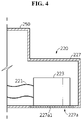
- FIG. 4 is a schematic cross-sectional view showing the internal configuration of the components of the battery pack according to an embodiment of the present disclosure. Additionally, FIG. 5 is a schematic cross-sectional view showing the internal configuration of the components of the battery pack according to an embodiment of the present disclosure.
- the storage unit 227 may have one open side through which the storage unit 227 is in communication with the inside of the pack housing 250.
- An electrical line 221 may be provided to establish an electrical connection between the cell assembly 210 and the resistor 223 through the open side of the storage unit 227.
- the storage unit 227 may include a discharge unit 227a.
- the discharge unit 227a may be configured to support the energy consumption unit 220 in a direction opposite to the discharge direction of the energy consumption unit 220.
- the storage unit 227 may include the discharge unit 227a configured to support the bottom of the energy consumption unit 220 in the upward direction. That is, the discharge unit 227a may be configured to support the energy consumption unit 220 in a direction opposite to the gravitational direction to place the energy consumption unit 220 in the storage unit 227.
- the discharge unit 227a may be configured to melt away by the heat generated by the energy consumption unit 220 to discharge at least part of the energy consumption unit 220 to the outside.
- the discharge unit 227a may include a material 227al that melts at the temperature between about 150°C and 300°C.
- the material may be, for example, paraffin or metal.
- the metal may be, for example, tin or lead.
- the present disclosure includes the discharge unit 227a configured to melt away by the heat generated by the energy consumption unit 220 to discharge at least part of the energy consumption unit 220 to the outside, thereby inducing the energy consumption unit 220 to be spontaneously discharged to the outside using the resistance heat generated from the energy consumption unit 220 without a separate discharge device. Accordingly, due to the simple configuration, it is possible to save the manufacturing cost and effectively reduce the malfunction likelihood.
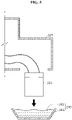
- FIG. 6 is a schematic cross-sectional view showing the internal configuration of the components of a battery pack according to another embodiment of the present disclosure. Additionally, FIG. 7 is a schematic cross-sectional view showing the internal configuration of the components of the battery pack according to another embodiment of the present disclosure.
- the storage unit 227 of the energy consumption unit 220A may include a discharge door 227b1.
- the discharge door 227b1 may be configured to support in a direction opposite to the discharge direction of the resistor 223 of the energy consumption unit 220A.
- the discharge door 227b1 may be closed to prevent the energy consumption unit 220A from being discharged.
- the discharge door 227b1 may be configured to be released from the closed state and be opened when thermal runaway occurs.
- the storage unit 227 may include a stop 227c and a hinge member 227d.
- the storage unit 227 may be configured to connect one side of the discharge door 227b1 of the hinge member 227d to the outer wall of the storage unit 227. That is, the discharge door 227b1 may be configured to rotatably move by the hinge member 227d.
- the stop 227c may be configured to keep the other side of the discharge door 227b1 from moving in the downward direction (gravitational direction).
- the stop 227c may be in the shape of a bar that extends in one direction.
- the stop 227c may be disposed on the outer wall (the lower wall) of the storage unit 227.
- the stop 227c may be configured to move in the extended lengthwise direction.
- the stop 227c may be configured to keep the discharge door 227b1 in the closed state or allow the discharge door 227b1 to rotatably move according to the location in the lengthwise direction.
- the battery pack 200 of the present disclosure may further include a cooling unit 240 configured to cool the energy consumption unit 220 discharged to the outside.
- the cooling unit 240 may include a water tank 243 and a refrigerant 241 received in the water tank 243.
- the refrigerant 241 may be, for example, an insulating oil having an electrically insulating property and a high specific heat.
- the cooling unit 240 may be configured to immerse the energy consumption unit 220 in the refrigerant 241 received in the water tank 243.
- the present disclosure further includes the cooling unit 240, thereby safely storing the energy consumption unit 220 discharged from the storage unit 227. That is, since the energy consumption unit 220 may generate high temperature by consuming the power of the cell assembly 210, and when contacting with an external device or the user, may be damaged, the present disclosure may quickly cool and safely store the energy consumption unit 220 using the cooling unit 240.
- the energy consumption unit 220 of the present disclosure may include an electrical line 221, a resistor 223 and a switch 225.
- the electrical line 221 may be electrically connected to the power terminal 214 of the at least one cell assembly 210.
- the power terminal 214 may be a negative power terminal or a positive power terminal.
- the cell assembly 210, the resistor 223 and the switch 225 may be interconnected by the electrical line 221.
- the electrical line 221 may include a metal wire and an electrically insulating coating that covers the wire.
- the resistor 223 may be electrically connected to the electrical line 221 and configured to consume the stored electrical energy of the cell assembly 210.
- the resistor 223 may include carbon, a metal or an oxidized metal having a predetermined specific electrical resistance or above.
- the metal may be, for example, alloys of copper, aluminum and nickel.
- the resistor 223 may be electrically connected to the positive electrode terminal and the negative electrode terminal of the cell assembly 210 to cause an electrical short circuit.
- the resistor 223 may be configured to convert the power of the cell assembly 210 into resistance heat.
- the switch 225 may be configured to control the electrical connection between the at least one cell assembly 210 and the resistor 223 by the on-off operation.
- the switch 225 may be provided on the electrical line 221.
- two switches 225 may be provided on two electrical lines 221 respectively.
- the switch 225 may be configured to control electrical connection between the cell assembly 210 and the resistor 223.
- the switch 225 is in an off state, the switch 225 may be open to disallow the electricity of the electrical line 221 to flow, and when the switch 225 is in an on state, the switch 225 may be closed to allow the electricity of the electrical line 221 to flow.
- the switch 225 may be configured to be turned on by a physical change made by the influence of the heat generated from the cell assembly 210.
- the switch 225 may be a temperature switch which opens or closes a contact point in response to the temperature using displacement resulting from expansion and contraction of a temperature sensing body such as bimetal with the temperature change of the cell assembly 210.
- the present disclosure includes the switch 225 which opens or closes the contact point in response to the temperature, so the switch 225 may operate using the temperature change of the cell assembly 210 without a separate device for controlling the switch 225. Accordingly, due to the simple configuration of the battery pack 200, it is possible to save the manufacturing cost and effectively reduce the malfunction likelihood.
- the battery pack 200 of the present disclosure may further include a sensor 262 and a control unit 260.
- the sensor 262 may be a gas detection sensor or a temperature sensor configured to sense thermal runaway of the plurality of battery cells 211.
- the sensor 262 may be disposed in the at least one cell assembly.
- control unit 260 when the control unit 260 receives a signal notifying thermal runaway from the sensor 262, the control unit 260 may be configured to transmit the signal to the switch 225 to electrically connect the cell assembly 210 to the resistor 223.
- the control unit 260 may include a communication line 261 to transmit the electrical signal to the switch 225.
- control unit 260 when the control unit 260 receives the signal notifying thermal runaway from the sensor 262, the control unit 260 may be configured to output a control signal for turning on the switch 225.
- the present disclosure further includes the control unit 260, thereby automatically controlling the switch 225 quickly when thermal runaway of the plurality of battery cells 211 is sensed. Accordingly, the present disclosure may quickly consume the power of the cell assembly 210 in which thermal runaway occurred, thereby increasing the safety.
- the battery pack 200 when comparing with the energy consumption unit 220 of FIG. 4 , may include the electrical line 221 of a different shape.
- the electrical line 221 of the energy consumption unit 220 may be in the shape of a coil.
- the resistor 223 When the resistor 223 is discharged out of the storage unit 227, the lengths of the coil shaped electrical line 221 may be elastically extended in the downward direction.
- the present disclosure includes the coil shaped electrical line 221, thereby reducing impacts caused by a fall of the resistor 223 using the elastic force of the coil shape when the resistor 223 is discharged out of the storage unit 227. Accordingly, it is possible to prevent the coil shaped electrical line 221 of the present disclosure from being cut when a force of the falling resistor 223 is transmitted to the electrical line 221.
- the battery pack 200 of the present disclosure may include at least two cell assemblies 210.
- the battery pack 200 may include three cell assemblies 210.
- the energy consumption unit 220 may be configured to discharge the cell assembly 210 including the battery cell 211 in which thermal runaway occurred among the at least two cell assemblies 210.
- the energy consumption unit 220 may be configured to discharge the other cell assembly 210 adjacent to the cell assembly 210 including the battery cell 211 in which thermal runaway occurred among the at least two cell assemblies 210.
- the present disclosure includes the energy consumption unit 220 configured to discharge the cell assembly 210 including the battery cell 211 in which thermal runaway occurred among the at least two cell assemblies 210, or configured to discharge the other cell assembly 210 adjacent to the cell assembly 210 including the battery cell 211 in which thermal runaway occurred among the at least two cell assemblies 210, thereby preventing propagation of thermal runaway from the cell assembly 210 to the adjacent other cell assembly 210 by consuming the power of the cell assembly 210 in which thermal runaway occurred or the cell assembly 210 adjacent to the cell assembly 210 in which thermal runaway occurred without needing to include the energy consumption unit 220 for each of the plurality of cell assemblies 210.
- thermal runaway occurs in one of the plurality of cell assemblies 210
- propagation of the thermal runaway to the adjacent other cell assembly 210 may be prevented by two methods.
- One of the methods quickly consumes the power of the cell assembly 210 including the battery cell 211 in which thermal runaway occurred among three cell assemblies 210, for example, below 30% as shown in FIG. 3 .
- the fast power consumption may reduce the thermal energy level of the cell assembly 210 in which thermal runaway occurred to a level at which the thermal runaway may not spread to the adjacent other cell assembly 210, thereby preventing the propagation of the thermal runaway to the other cell assemblies disposed at the front end and the rear end.
- the other method consumes the power of the front cell assembly 210 and the rear cell assembly 210 adjacent to the cell assembly 210 in which thermal runaway occurred among three cell assemblies. That is, when there are temperature rises of the other cell assemblies 210 disposed at the front end and the rear end by the intermediate cell assembly 210 in which thermal runaway occurred, the power of the other cell assemblies 210 has been already consumed, for example, below 30%, so thermal runaway is less likely to occur, thereby preventing the propagation of the thermal runaway.
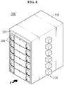
- FIG. 8 is a schematic perspective view of a battery rack according to an embodiment of the present disclosure.
- up, down, left and right directions may be defined when the battery rack is viewed from the F direction.
- the battery rack 300 may include a rack case 310 that accommodates the plurality of battery packs 200.
- the rack case 310 may be configured to receive the plurality of battery packs 200 vertically stacked.
- a part of the energy consumption unit 220 provided in each of the plurality of battery packs 200 may extend out of the rack case 310. That is, the energy consumption unit 220 may be disposed on the outer side of the battery rack 300 through a part of the rack case 310.
- the rack case 310 may be configured to be open to at least one side (right side). However, the rack case 310 may be configured to close the open side after the energy consumption unit 220 is installed.
- the battery rack 300 may further include a central control unit 320 including a Battery Management System (BMS) inside or outside of the rack case 310.
- BMS Battery Management System
- an energy storage system may include at least two battery racks 300.
- the at least two battery racks 300 may be arranged in a direction.
- the energy storage system may include three battery racks 300 arranged in a direction.
- the energy storage system may include a central control unit (not shown) to control the charge/discharge of the three battery racks 300.
- Battery pack 250 Pack housing 210: Cell assembly 211: Battery cell 220: Energy consumption unit 221, 223, 225: Electrical line, Resistor, Switch 227: Storage unit 227b, 227b1: Discharge unit, Discharge door 227c, 227d: Stop, Hinge member 240, 241, 243: Cooling unit, Refrigerant, Water tank 260, 261, 262: Control unit, Communication line, Sensor 300: Battery rack
Landscapes
- Chemical & Material Sciences (AREA)
- Chemical Kinetics & Catalysis (AREA)
- Electrochemistry (AREA)
- General Chemical & Material Sciences (AREA)
- Engineering & Computer Science (AREA)
- Manufacturing & Machinery (AREA)
- Microelectronics & Electronic Packaging (AREA)
- Battery Mounting, Suspending (AREA)
- Secondary Cells (AREA)
- Charge And Discharge Circuits For Batteries Or The Like (AREA)
Abstract
Description
- The present disclosure relates to a battery pack, a battery rack comprising the same and an energy storage system, and more particularly, to a battery pack with improved safety against thermal runaway of a plurality of battery cells.
- The present application claims the benefit of
Korean Patent Application No. 10-2020-0061807 filed on May 22, 2020 - Currently, commercially available secondary batteries include nickel cadmium batteries, nickel hydride batteries, nickel zinc batteries, lithium secondary batteries, etc., and among them, lithium secondary batteries have little or no memory effect, and thus they are gaining more attention than nickel-based secondary batteries for their advantages that recharging can be done whenever it is convenient, the self-discharge rate is very low and the energy density is high.
- The lithium secondary battery mainly uses lithium-based oxide and a carbon material for a positive electrode active material and a negative electrode active material respectively. The lithium secondary battery includes an electrode assembly including a positive electrode plate coated with the positive electrode active material, a negative electrode plate coated with the negative electrode active material and a separator interposed between, and a hermetically sealed packaging material or battery pouch case in which the electrode assembly is received together with an electrolyte solution.
- More recently, secondary batteries are being widely used in not only small devices such as portable electronic products but also medium- and large-scale devices such as vehicles and energy storage systems (ESSs). For use in medium- and large-scale devices, many secondary batteries are electrically connected to increase the capacity and output. In particular, pouch-type secondary batteries are widely used in medium- and large-scale devices because they are easy to stack.
- With the growing need for a large-capacity structure for use as an energy storage source, there is an increasing demand for a battery pack including a plurality of secondary batteries electrically connected in series and/or parallel, a battery module to receive the secondary batteries and a battery management system (BMS).
- However, the battery pack or rack includes a plurality of battery modules, and when a fire or explosion occurs due to thermal runaway in any of the plurality of secondary batteries of each battery module, heat or flames may spread to adjacent secondary batteries, causing secondary fires or explosions, and accordingly, many efforts have been made to prevent secondary fires or explosions.
- Accordingly, when thermal runaway occurs in any secondary battery of the battery pack or the battery rack, thermal runaway of the battery pack has been mitigated by cooling the battery pack or discharging stored electrical energy.
- However, in the process of discharging the electrical energy stored in the battery pack, resistance heat of a resistor that consumes the electrical energy may cause damage to the internal components of the battery pack or increase the temperature of the plurality of secondary batteries, causing thermal runaway of the secondary battery or impeding the cooling of the plurality of secondary batteries.
- The present disclosure is designed to solve the above-described problem, and therefore the present disclosure is directed to providing a battery pack with improved safety against thermal runaway of a plurality of battery cells.
- These and other objects and advantages of the present disclosure can be understood by the following description, and will be apparent from the embodiments of the present disclosure. In addition, it will be readily appreciated that the objects and advantages of the present disclosure can be realized by means and combinations thereof.
- To achieve the above-described object, a battery pack according to the present disclosure includes at least one cell assembly including a plurality of battery cells, an energy consumption unit configured to discharge the at least one cell assembly when thermal runaway occurs in at least one of the plurality of battery cells, and a storage unit in which the energy consumption unit is received inside, and configured to discharge at least part of the energy consumption unit to outside when the energy consumption unit discharges the cell assembly.
- Additionally, the storage unit may include a discharge unit configured to support the energy consumption unit in a direction opposite to a discharge direction of the energy consumption unit, and the discharge unit may be configured to melt away by heat generated by the energy consumption unit to discharge at least part of the energy consumption unit to the outside.
- Furthermore, the storage unit may include a discharge door which is closed to support in a direction opposite to a discharge direction of the energy consumption unit, and the discharge door may be configured to be released from the closed state and be opened when the thermal runaway occurs.
- Additionally, the battery pack may further include a cooling unit including a refrigerant to cool the energy consumption unit discharged to the outside.
- Further, the energy consumption unit may include a switch, and a resistor which is electrically connected to the at least one cell assembly by operation of the switch and configured to consume electrical energy stored in the at least one cell assembly.
- Additionally, the switch may be configured to be turned on by a physical change made by influence of the heat generated from the cell assembly.
- Furthermore, the battery pack may further include a sensor to sense the thermal runaway in the plurality of battery cells, and a control unit to output a control signal for turning on the switch to electrically connect the cell assembly to the resistor when the control unit receives a signal notifying the thermal runaway from the sensor.
- Additionally, the cell assembly, the resistor and the switch may be interconnected by an electrical line, and the electrical line may have a coil shape.
- Furthermore, the battery pack may include at least two cell assemblies, and the energy consumption unit may be configured to discharge the cell assembly including the battery cell in which the thermal runaway occurred among the at least two cell assemblies or other cell assembly adjacent to the cell assembly including the battery cell in which the thermal runaway occurred.
- Further, to achieve the above-described object, a battery rack according to the present disclosure includes a battery pack and a rack case in which the battery pack is received.
- Additionally, to achieve the above-described object, an energy storage system according to the present disclosure includes at least one battery rack.
- According to an aspect of the present disclosure, the battery pack of the present disclosure includes the energy consumption unit and the storage unit, thereby preventing propagation of thermal runaway to the adjacent other battery cell or the other cell assembly when thermal runaway occurs in any of the plurality of battery cells. Further, the present disclosure may discharge the energy consumption unit out of the storage unit, thereby preventing the temperature rise of the component of the battery pack, for example, the other cell assembly caused by the resistance heat generated from the energy consumption unit. Further, the energy consumption unit discharged out of the storage unit may be cooled quickly when meeting the external air, thereby preventing damage to an external device by the heat of the energy consumption unit.
- Additionally, according to an aspect of an embodiment of the present disclosure, the battery pack of the present disclosure includes the discharge unit configured to melt away by the heat generated by the energy consumption unit to discharge at least part of the energy consumption unit to the outside, thereby inducing the energy consumption unit to be spontaneously discharged to the outside using the resistance heat generated from the energy consumption unit without a separate discharge device. Accordingly, due to the simple configuration, it is possible to save the manufacturing cost and effectively reduce the malfunction likelihood.
- Further, according to another aspect of the present disclosure, the battery pack of the present disclosure includes the coil shaped electrical line, thereby reducing impacts caused by a fall of the resistor using the elastic force of the coil shape when the resistor is discharged out of the storage unit. Accordingly, it is possible to prevent the coil shaped electrical line of the present disclosure from being cut when a force of the falling resistor is transmitted to the electrical line.
- The accompanying drawings illustrate preferred embodiments of the present disclosure and, together with the detailed disclosure, serve to provide further understanding of the technical spirit of the present disclosure. However, the present disclosure is not to be construed as being limited to the drawings.
-
FIG. 1 is a schematic perspective view of a battery pack according to an embodiment of the present disclosure. -
FIG. 2 is a schematic perspective view of cell assemblies of a battery pack according to an embodiment of the present disclosure. -
FIG. 3 is a schematic conceptual diagram showing components of a battery pack according to an embodiment of the present disclosure. -
FIG. 4 is a schematic cross-sectional view of the battery pack ofFIG. 1 , taken along the line C-C'. -
FIG. 5 is a schematic cross-sectional view showing the internal configuration of components of a battery pack according to an embodiment of the present disclosure. -
FIG. 6 is a schematic cross-sectional view showing the internal configuration of components of a battery pack according to another embodiment of the present disclosure. -
FIG. 7 is a schematic cross-sectional view showing the internal configuration of components of a battery pack according to another embodiment of the present disclosure. -
FIG. 8 is a schematic perspective view of a battery rack according to an embodiment of the present disclosure. - Hereinafter, the preferred embodiments of the present disclosure will be described in detail with reference to the accompanying drawings. Prior to the description, it should be understood that the terms or words used in the specification and the appended claims should not be construed as being limited to general and dictionary meanings, but rather interpreted based on the meanings and concepts corresponding to the technical aspects of the present disclosure on the basis of the principle that the inventor is allowed to define the terms appropriately for the best explanation.
- Therefore, the embodiments described herein and illustrations shown in the drawings are just a most preferred embodiment of the present disclosure, but not intended to fully describe the technical aspects of the present disclosure, so it should be understood that a variety of other equivalents and modifications could have been made thereto at the time that the application was filed.
-
FIG. 1 is a schematic perspective view of a battery pack according to an embodiment of the present disclosure.FIG. 2 is a schematic perspective view of cell assemblies of the battery pack according to an embodiment of the present disclosure. Additionally,FIG. 3 is a schematic conceptual diagram showing the components of the battery pack according to an embodiment of the present disclosure. InFIG. 1 , the X axis direction is the right direction, the Y axis direction is the rear direction, and the Z axis direction is the up direction. - Referring to
FIGS. 1 to 3 , thebattery pack 200 according to the present disclosure may include at least onecell assembly 210 including a plurality ofbattery cells 211, anenergy consumption unit 220 and astorage unit 227. - Specifically, the
battery cell 211 may be a pouch-type battery cell 211. For example, as shown inFIG. 2 , each of threecell assemblies 210 may include 21 pouch-type battery cells 211 stacked side by side in the front-rear direction (y direction). - In particular, the pouch-
type battery cell 211 may include an electrode assembly (not shown), an electrolyte solution (not shown) and a pouch. - Further, as shown in
FIG. 2 , thebattery cell 211 may have anelectrode terminal 211a at two opposite ends (in the X direction) with respect to the center of thebattery cell 211. For example, as shown inFIG. 2 , eachbattery cell 211 of thecell assembly 210 may have apositive electrode terminal 211a and a negative electrode terminal (not shown) extending in the horizontal direction (X direction). - However, the
battery pack 200 according to the present disclosure is not limited to the above-described pouch-type battery cell 211 and may employ various types ofbattery cells 211 known at the time of filing the patent application. - Additionally, the
battery pack 200 may include at least onebusbar 121 configured to electrically connect the plurality ofbattery cells 211 and at least twobusbar frames 120 configured to mount the at least onebusbar 121 on the outer side. The at least twobusbar frames 120 may be provided on the left and right sides (X direction) of thecell assembly 210 respectively. - Specifically, the
busbar 121 may include a conductive metal, for example, copper, aluminum and nickel. - Additionally, the
busbar frame 120 may include an electrically insulating material. For example, thebusbar frame 120 may include a plastic material. More specifically, the plastic material may be polyvinyl chloride. - Meanwhile, the
battery pack 200 may include apack housing 250. Thepack housing 250 may have an internal space in which the at least onecell assembly 210 is received. For example, thepack housing 250 may accommodate threecell assemblies 210. - Meanwhile, when thermal runaway occurs in at least one of the plurality of
battery cells 211, theenergy consumption unit 220 may be configured to discharge the at least onecell assembly 210. That is, theenergy consumption unit 220 may be electrically connected to a power terminal 214 (a positive power terminal and a negative power terminal) of thecell assembly 210 to intentionally cause an electrical short circuit. Accordingly, the power of thecell assembly 210 electrically connected to theenergy consumption unit 220 may be consumed quickly. In other words, theenergy consumption unit 220 may be configured to consume electrical energy of thecell assembly 210 quickly. - Here, the 'thermal runaway' refers to a positive feedback that the temperature rise of any of the plurality of
battery cells 211 increases the energy release rate of thebattery cell 211 and theadjacent battery cell 211, and in turn, this will accelerate the temperature rise. For example, thermal runaway may occur at 230°C or above, and thebattery cell 211 may spontaneously ignite. - For example, the
energy consumption unit 220 may be configured to apply power to theresistor 223, a power resistor or an electric motor to consume the power of thebattery pack 200. - Additionally, the
energy consumption unit 220 may include an electrical short circuit. The electrical short circuit may be a circuit electrically connected between theresistor 223 of theenergy consumption unit 220 and thecell assembly 210. That is, both the external positive electrode terminal and the external negative electrode terminal of thecell assembly 210 may be electrically connected to theresistor 223 to cause an intentional electrical short circuit. - Further, the
storage unit 227 may be configured to receive theenergy consumption unit 220 inside. Thestorage unit 227 may have, for example, a rectangular box shaped frame. Theenergy consumption unit 220 may be positioned in the internal space of the rectangular box shaped frame 235. Thestorage unit 227 may be connected to the outer wall of thepack housing 250. - For example, the
storage unit 227 may have an open part so that thestorage unit 227 is in communication with the inside of thepack housing 250. However, thestorage unit 227 is not limited thereto, and may not be in communication with the inside of thepack housing 250. That is, thestorage unit 227 may have a space that is isolated from the outside. - Additionally, when the
energy consumption unit 220 discharges thecell assembly 210, thestorage unit 227 may be configured to discharge at least part of theenergy consumption unit 220 to the outside. That is, when theenergy consumption unit 220 discharges thecell assembly 210, a part of thestorage unit 227 may be open so that theenergy consumption unit 220 moves to the outside. - According to this configuration of the present disclosure, the present disclosure includes the
energy consumption unit 220 and thestorage unit 227, thereby preventing propagation of thermal runaway to the adjacentother battery cell 211 or theother cell assembly 210 when thermal runaway occurs in any of the plurality ofbattery cells 211. Further, the present disclosure may discharge theenergy consumption unit 220 out of thestorage unit 227, thereby preventing the temperature rise of the component of thebattery pack 200, for example, theother cell assembly 210 caused by the resistance heat generated from theenergy consumption unit 220. Further, theenergy consumption unit 220 discharged out of thestorage unit 227 may be cooled quickly when meeting the external air, thereby preventing damage to an external device by the heat of theenergy consumption unit 220. -
FIG. 4 is a schematic cross-sectional view showing the internal configuration of the components of the battery pack according to an embodiment of the present disclosure. Additionally,FIG. 5 is a schematic cross-sectional view showing the internal configuration of the components of the battery pack according to an embodiment of the present disclosure. - Referring to
FIGS. 4 and5 together withFIG. 2 , thestorage unit 227 may have one open side through which thestorage unit 227 is in communication with the inside of thepack housing 250. Anelectrical line 221 may be provided to establish an electrical connection between thecell assembly 210 and theresistor 223 through the open side of thestorage unit 227. - Further, the
storage unit 227 may include adischarge unit 227a. Thedischarge unit 227a may be configured to support theenergy consumption unit 220 in a direction opposite to the discharge direction of theenergy consumption unit 220. For example, as shown inFIG. 4 , thestorage unit 227 may include thedischarge unit 227a configured to support the bottom of theenergy consumption unit 220 in the upward direction. That is, thedischarge unit 227a may be configured to support theenergy consumption unit 220 in a direction opposite to the gravitational direction to place theenergy consumption unit 220 in thestorage unit 227. - Additionally, the
discharge unit 227a may be configured to melt away by the heat generated by theenergy consumption unit 220 to discharge at least part of theenergy consumption unit 220 to the outside. For example, thedischarge unit 227a may include a material 227al that melts at the temperature between about 150°C and 300°C. The material may be, for example, paraffin or metal. The metal may be, for example, tin or lead. - According to this configuration of the present disclosure, the present disclosure includes the
discharge unit 227a configured to melt away by the heat generated by theenergy consumption unit 220 to discharge at least part of theenergy consumption unit 220 to the outside, thereby inducing theenergy consumption unit 220 to be spontaneously discharged to the outside using the resistance heat generated from theenergy consumption unit 220 without a separate discharge device. Accordingly, due to the simple configuration, it is possible to save the manufacturing cost and effectively reduce the malfunction likelihood. -
FIG. 6 is a schematic cross-sectional view showing the internal configuration of the components of a battery pack according to another embodiment of the present disclosure. Additionally,FIG. 7 is a schematic cross-sectional view showing the internal configuration of the components of the battery pack according to another embodiment of the present disclosure. - Referring to
FIGS. 6 and7 together withFIG. 3 , thestorage unit 227 of theenergy consumption unit 220A according to another embodiment of the present disclosure may include a discharge door 227b1. The discharge door 227b1 may be configured to support in a direction opposite to the discharge direction of theresistor 223 of theenergy consumption unit 220A. The discharge door 227b1 may be closed to prevent theenergy consumption unit 220A from being discharged. The discharge door 227b1 may be configured to be released from the closed state and be opened when thermal runaway occurs. - For example, the
storage unit 227 may include astop 227c and ahinge member 227d. Thestorage unit 227 may be configured to connect one side of the discharge door 227b1 of thehinge member 227d to the outer wall of thestorage unit 227. That is, the discharge door 227b1 may be configured to rotatably move by thehinge member 227d. Thestop 227c may be configured to keep the other side of the discharge door 227b1 from moving in the downward direction (gravitational direction). - That is, the
stop 227c may be in the shape of a bar that extends in one direction. Thestop 227c may be disposed on the outer wall (the lower wall) of thestorage unit 227. Thestop 227c may be configured to move in the extended lengthwise direction. Thestop 227c may be configured to keep the discharge door 227b1 in the closed state or allow the discharge door 227b1 to rotatably move according to the location in the lengthwise direction. - Referring back to
FIGS. 4 and5 , thebattery pack 200 of the present disclosure may further include acooling unit 240 configured to cool theenergy consumption unit 220 discharged to the outside. For example, thecooling unit 240 may include awater tank 243 and a refrigerant 241 received in thewater tank 243. The refrigerant 241 may be, for example, an insulating oil having an electrically insulating property and a high specific heat. When theenergy consumption unit 220 is discharged from thestorage unit 227, thecooling unit 240 may be configured to immerse theenergy consumption unit 220 in the refrigerant 241 received in thewater tank 243. - According to this configuration of the present disclosure, the present disclosure further includes the
cooling unit 240, thereby safely storing theenergy consumption unit 220 discharged from thestorage unit 227. That is, since theenergy consumption unit 220 may generate high temperature by consuming the power of thecell assembly 210, and when contacting with an external device or the user, may be damaged, the present disclosure may quickly cool and safely store theenergy consumption unit 220 using thecooling unit 240. - Referring back to
FIGS. 1 to 4 , theenergy consumption unit 220 of the present disclosure may include anelectrical line 221, aresistor 223 and aswitch 225. - Specifically, the
electrical line 221 may be electrically connected to thepower terminal 214 of the at least onecell assembly 210. Thepower terminal 214 may be a negative power terminal or a positive power terminal. Thecell assembly 210, theresistor 223 and theswitch 225 may be interconnected by theelectrical line 221. Theelectrical line 221 may include a metal wire and an electrically insulating coating that covers the wire. - Additionally, the
resistor 223 may be electrically connected to theelectrical line 221 and configured to consume the stored electrical energy of thecell assembly 210. For example, theresistor 223 may include carbon, a metal or an oxidized metal having a predetermined specific electrical resistance or above. The metal may be, for example, alloys of copper, aluminum and nickel. - Further, the
resistor 223 may be electrically connected to the positive electrode terminal and the negative electrode terminal of thecell assembly 210 to cause an electrical short circuit. Theresistor 223 may be configured to convert the power of thecell assembly 210 into resistance heat. - Additionally, the
switch 225 may be configured to control the electrical connection between the at least onecell assembly 210 and theresistor 223 by the on-off operation. Theswitch 225 may be provided on theelectrical line 221. For example, as shown inFIG. 1 , twoswitches 225 may be provided on twoelectrical lines 221 respectively. When comparing with inclusion of oneswitch 225, in case that the twoswitches 225 are provided, it is possible to prevent unnecessary power consumption of thecell assembly 210 caused by malfunction of any of theswitches 225. Theswitch 225 may be configured to control electrical connection between thecell assembly 210 and theresistor 223. - For example, the
switch 225 is in an off state, theswitch 225 may be open to disallow the electricity of theelectrical line 221 to flow, and when theswitch 225 is in an on state, theswitch 225 may be closed to allow the electricity of theelectrical line 221 to flow. - Further, the
switch 225 may be configured to be turned on by a physical change made by the influence of the heat generated from thecell assembly 210. For example, theswitch 225 may be a temperature switch which opens or closes a contact point in response to the temperature using displacement resulting from expansion and contraction of a temperature sensing body such as bimetal with the temperature change of thecell assembly 210. - According to this configuration of the present disclosure, the present disclosure includes the
switch 225 which opens or closes the contact point in response to the temperature, so theswitch 225 may operate using the temperature change of thecell assembly 210 without a separate device for controlling theswitch 225. Accordingly, due to the simple configuration of thebattery pack 200, it is possible to save the manufacturing cost and effectively reduce the malfunction likelihood. - Referring back to
FIGS. 1 to 4 , thebattery pack 200 of the present disclosure may further include asensor 262 and acontrol unit 260. Thesensor 262 may be a gas detection sensor or a temperature sensor configured to sense thermal runaway of the plurality ofbattery cells 211. For example, thesensor 262 may be disposed in the at least one cell assembly. - Additionally, when the
control unit 260 receives a signal notifying thermal runaway from thesensor 262, thecontrol unit 260 may be configured to transmit the signal to theswitch 225 to electrically connect thecell assembly 210 to theresistor 223. Thecontrol unit 260 may include acommunication line 261 to transmit the electrical signal to theswitch 225. For example, when thecontrol unit 260 receives the signal notifying thermal runaway from thesensor 262, thecontrol unit 260 may be configured to output a control signal for turning on theswitch 225. - According to this configuration of the present disclosure, the present disclosure further includes the
control unit 260, thereby automatically controlling theswitch 225 quickly when thermal runaway of the plurality ofbattery cells 211 is sensed. Accordingly, the present disclosure may quickly consume the power of thecell assembly 210 in which thermal runaway occurred, thereby increasing the safety. - Referring back to
FIGS. 6 and7 , when comparing with theenergy consumption unit 220 ofFIG. 4 , thebattery pack 200 according to another embodiment of the present disclosure may include theelectrical line 221 of a different shape. For example, as shown inFIG. 7 , theelectrical line 221 of theenergy consumption unit 220 may be in the shape of a coil. When theresistor 223 is discharged out of thestorage unit 227, the lengths of the coil shapedelectrical line 221 may be elastically extended in the downward direction. - According to this configuration of the present disclosure, the present disclosure includes the coil shaped
electrical line 221, thereby reducing impacts caused by a fall of theresistor 223 using the elastic force of the coil shape when theresistor 223 is discharged out of thestorage unit 227. Accordingly, it is possible to prevent the coil shapedelectrical line 221 of the present disclosure from being cut when a force of the fallingresistor 223 is transmitted to theelectrical line 221. - Referring back to
FIGS. 1 to 4 , thebattery pack 200 of the present disclosure may include at least twocell assemblies 210. For example, as shown inFIG. 2 , thebattery pack 200 may include threecell assemblies 210. - Additionally, the
energy consumption unit 220 may be configured to discharge thecell assembly 210 including thebattery cell 211 in which thermal runaway occurred among the at least twocell assemblies 210. - Further, the
energy consumption unit 220 may be configured to discharge theother cell assembly 210 adjacent to thecell assembly 210 including thebattery cell 211 in which thermal runaway occurred among the at least twocell assemblies 210. - According to this configuration of the present disclosure, the present disclosure includes the
energy consumption unit 220 configured to discharge thecell assembly 210 including thebattery cell 211 in which thermal runaway occurred among the at least twocell assemblies 210, or configured to discharge theother cell assembly 210 adjacent to thecell assembly 210 including thebattery cell 211 in which thermal runaway occurred among the at least twocell assemblies 210, thereby preventing propagation of thermal runaway from thecell assembly 210 to the adjacentother cell assembly 210 by consuming the power of thecell assembly 210 in which thermal runaway occurred or thecell assembly 210 adjacent to thecell assembly 210 in which thermal runaway occurred without needing to include theenergy consumption unit 220 for each of the plurality ofcell assemblies 210. - That is, when thermal runaway occurs in one of the plurality of
cell assemblies 210, propagation of the thermal runaway to the adjacentother cell assembly 210 may be prevented by two methods. One of the methods quickly consumes the power of thecell assembly 210 including thebattery cell 211 in which thermal runaway occurred among threecell assemblies 210, for example, below 30% as shown inFIG. 3 . The fast power consumption may reduce the thermal energy level of thecell assembly 210 in which thermal runaway occurred to a level at which the thermal runaway may not spread to the adjacentother cell assembly 210, thereby preventing the propagation of the thermal runaway to the other cell assemblies disposed at the front end and the rear end. - Additionally, the other method consumes the power of the
front cell assembly 210 and therear cell assembly 210 adjacent to thecell assembly 210 in which thermal runaway occurred among three cell assemblies. That is, when there are temperature rises of theother cell assemblies 210 disposed at the front end and the rear end by theintermediate cell assembly 210 in which thermal runaway occurred, the power of theother cell assemblies 210 has been already consumed, for example, below 30%, so thermal runaway is less likely to occur, thereby preventing the propagation of the thermal runaway. -
FIG. 8 is a schematic perspective view of a battery rack according to an embodiment of the present disclosure. For reference, inFIG. 8 , up, down, left and right directions may be defined when the battery rack is viewed from the F direction. - Referring to
FIG. 8 , thebattery rack 300 according to an embodiment of the present disclosure may include arack case 310 that accommodates the plurality of battery packs 200. Therack case 310 may be configured to receive the plurality of battery packs 200 vertically stacked. In this instance, a part of theenergy consumption unit 220 provided in each of the plurality of battery packs 200 may extend out of therack case 310. That is, theenergy consumption unit 220 may be disposed on the outer side of thebattery rack 300 through a part of therack case 310. - Further, the
rack case 310 may be configured to be open to at least one side (right side). However, therack case 310 may be configured to close the open side after theenergy consumption unit 220 is installed. - Additionally, the
battery rack 300 may further include acentral control unit 320 including a Battery Management System (BMS) inside or outside of therack case 310. - Meanwhile, an energy storage system (not shown) according to an embodiment of the present disclosure may include at least two battery racks 300. The at least two
battery racks 300 may be arranged in a direction. For example, although not shown, the energy storage system may include threebattery racks 300 arranged in a direction. The energy storage system may include a central control unit (not shown) to control the charge/discharge of the threebattery racks 300. - The terms indicating directions as used herein such as upper, lower, left, right, front and rear are used for convenience of description only, and it is obvious to those skilled in the art that the term may change depending on the position of the stated element or an observer.
- While the present disclosure has been hereinabove described with regard to a limited number of embodiments and drawings, the present disclosure is not limited thereto and it is obvious to those skilled in the art that various modifications and changes may be made thereto within the technical aspects of the present disclosure and the equivalent scope of the appended claims.
-
200: Battery pack 250: Pack housing 210: Cell assembly 211: Battery cell 220: Energy consumption unit 221, 223, 225: Electrical line, Resistor, Switch 227: Storage unit 227b, 227b1: Discharge unit, Discharge door 227c, 227d: Stop, Hinge member 240, 241, 243: Cooling unit, Refrigerant, Water tank 260, 261, 262: Control unit, Communication line, Sensor 300: Battery rack
Claims (11)
- A battery pack, comprising:at least one cell assembly including a plurality of battery cells;an energy consumption unit configured to discharge the at least one cell assembly when thermal runaway occurs in at least one of the plurality of battery cells; anda storage unit in which the energy consumption unit is received inside, and configured to discharge at least part of the energy consumption unit to outside when the energy consumption unit discharges the cell assembly.
- The battery pack according to claim 1, wherein the storage unit includes a discharge unit configured to support the energy consumption unit in a direction opposite to a discharge direction of the energy consumption unit, and
the discharge unit is configured to melt away by heat generated by the energy consumption unit to discharge at least part of the energy consumption unit to the outside. - The battery pack according to claim 1, wherein the storage unit includes a discharge door which is closed to support in a direction opposite to a discharge direction of the energy consumption unit, and
the discharge door is configured to be released from the closed state and be opened when the thermal runaway occurs. - The battery pack according to claim 1, further comprising:
a cooling unit including a refrigerant to cool the energy consumption unit discharged to the outside. - The battery pack according to claim 1, wherein the energy consumption unit includes:a switch; anda resistor which is electrically connected to the at least one cell assembly by operation of the switch and configured to consume electrical energy stored in the at least one cell assembly.
- The battery pack according to claim 5, wherein the switch is configured to be turned on by a physical change made by influence of the heat generated from the cell assembly.
- The battery pack according to claim 5, further comprising:a sensor to sense the thermal runaway in the plurality of battery cells; anda control unit to output a control signal for turning on the switch to electrically connect the cell assembly to the resistor when the control unit receives a signal notifying the thermal runaway from the sensor.
- The battery pack according to claim 5, wherein the cell assembly, the resistor and the switch are interconnected by an electrical line, and
the electrical line has a coil shape. - The battery pack according to claim 1, wherein the battery pack includes at least two cell assemblies, and
the energy consumption unit is configured to discharge the cell assembly including the battery cell in which the thermal runaway occurred among the at least two cell assemblies or other cell assembly adjacent to the cell assembly including the battery cell in which the thermal runaway occurred. - A battery rack, comprising:the battery pack according to any one of claims 1 to 9, anda rack case in which the battery pack is received.
- An energy storage system comprising at least two battery racks according to claim 10.
Applications Claiming Priority (2)
| Application Number | Priority Date | Filing Date | Title |
|---|---|---|---|
| KR1020200061807A KR20210144440A (en) | 2020-05-22 | 2020-05-22 | Battery Pack, and Battery Rack Comprising the Same, and Energy Storage System |
| PCT/KR2021/005569 WO2021235738A1 (en) | 2020-05-22 | 2021-05-03 | Battery pack, battery rack including same, and power storage device |
Publications (2)
| Publication Number | Publication Date |
|---|---|
| EP4047714A1 true EP4047714A1 (en) | 2022-08-24 |
| EP4047714A4 EP4047714A4 (en) | 2024-03-27 |
Family
ID=78708751
Family Applications (1)
| Application Number | Title | Priority Date | Filing Date |
|---|---|---|---|
| EP21807849.1A Pending EP4047714A4 (en) | 2020-05-22 | 2021-05-03 | Battery pack, battery rack including same, and power storage device |
Country Status (7)
| Country | Link |
|---|---|
| US (1) | US20220367928A1 (en) |
| EP (1) | EP4047714A4 (en) |
| JP (1) | JP7342266B2 (en) |
| KR (1) | KR20210144440A (en) |
| CN (1) | CN114747064A (en) |
| AU (1) | AU2021275355A1 (en) |
| WO (1) | WO2021235738A1 (en) |
Cited By (1)
| Publication number | Priority date | Publication date | Assignee | Title |
|---|---|---|---|---|
| FR3141805A1 (en) * | 2022-11-07 | 2024-05-10 | Safran | Battery provided with a discharge during thermal runaway and corresponding control method. |
Family Cites Families (10)
| Publication number | Priority date | Publication date | Assignee | Title |
|---|---|---|---|---|
| WO2008079062A1 (en) * | 2006-12-22 | 2008-07-03 | Volvo Technology Corporation | Method and arrangement for discharging an energy storage system for electrical energy |
| JP2011120423A (en) | 2009-12-07 | 2011-06-16 | Sharp Corp | Battery system |
| JP5722251B2 (en) * | 2012-02-27 | 2015-05-20 | 株式会社東芝 | Battery pack, secondary battery device and electric vehicle |
| JP6179719B2 (en) | 2013-10-28 | 2017-08-16 | 三菱自動車工業株式会社 | Battery device |
| JP6440116B2 (en) * | 2014-12-26 | 2018-12-19 | パナソニックIpマネジメント株式会社 | Battery pack and adapter |
| CN110392956B (en) * | 2017-01-09 | 2023-06-23 | 米沃奇电动工具公司 | Battery pack |
| JP6711455B2 (en) * | 2017-04-07 | 2020-06-17 | 株式会社村田製作所 | Battery charge/discharge control device |
| KR102631549B1 (en) * | 2018-05-28 | 2024-01-30 | 주식회사 엘지에너지솔루션 | Self-heating system of battery pack for preventing undervoltage in low-temperature environment and manufacturing method thereof |
| US11621441B2 (en) * | 2018-07-27 | 2023-04-04 | The Boeing Company | Li-Ion battery high voltage distribution system architecture |
| KR20200061807A (en) | 2018-11-26 | 2020-06-03 | 실리콘 디스플레이 (주) | Apparatus for measuring contrast ratio of image sensor and method for measuring the same |
-
2020
- 2020-05-22 KR KR1020200061807A patent/KR20210144440A/en unknown
-
2021
- 2021-05-03 WO PCT/KR2021/005569 patent/WO2021235738A1/en unknown
- 2021-05-03 US US17/771,178 patent/US20220367928A1/en active Pending
- 2021-05-03 JP JP2022530992A patent/JP7342266B2/en active Active
- 2021-05-03 EP EP21807849.1A patent/EP4047714A4/en active Pending
- 2021-05-03 AU AU2021275355A patent/AU2021275355A1/en active Pending
- 2021-05-03 CN CN202180006857.2A patent/CN114747064A/en active Pending
Cited By (1)
| Publication number | Priority date | Publication date | Assignee | Title |
|---|---|---|---|---|
| FR3141805A1 (en) * | 2022-11-07 | 2024-05-10 | Safran | Battery provided with a discharge during thermal runaway and corresponding control method. |
Also Published As
| Publication number | Publication date |
|---|---|
| JP7342266B2 (en) | 2023-09-11 |
| US20220367928A1 (en) | 2022-11-17 |
| JP2023505049A (en) | 2023-02-08 |
| WO2021235738A1 (en) | 2021-11-25 |
| EP4047714A4 (en) | 2024-03-27 |
| AU2021275355A1 (en) | 2022-05-26 |
| CN114747064A (en) | 2022-07-12 |
| KR20210144440A (en) | 2021-11-30 |
Similar Documents
| Publication | Publication Date | Title |
|---|---|---|
| US11870094B2 (en) | Battery module, battery rack comprising same, and power storage device | |
| KR102248229B1 (en) | Battery Module Having Gas Discharge Structure | |
| EP3309859B1 (en) | Battery module | |
| JP5804540B2 (en) | Battery pack with improved safety | |
| KR101130050B1 (en) | Middle or Large-sized Battery Pack of Improved Safety | |
| US20230335846A1 (en) | Battery pack, vehicle, and electronic device comprising same | |
| US20220359922A1 (en) | Battery rack and energy storage system | |
| KR20160006000A (en) | Battery module exhibiting prevention of overcurrent | |
| US20220294035A1 (en) | Battery pack and battery rack and energy storage system comprising the same | |
| EP4199231A1 (en) | Battery pack having structure reducing temperature of venting gas and blocking external emission of spark | |
| US11158901B2 (en) | Lithium secondary battery pack including thermal expansion tape fixing pouch type battery cells and method of manufacturing same | |
| EP4047714A1 (en) | Battery pack, battery rack including same, and power storage device | |
| CN114097132A (en) | Battery holder and energy storage device including the same | |
| US20230268610A1 (en) | Battery module, battery pack, and vehicle | |
| CN116636073A (en) | Battery module having structure for blocking inflow of oxygen during heat propagation | |
| KR20230039122A (en) | Battery module with improved thermal runaway transition prevention performance | |
| KR20210134164A (en) | Battery Pack and Electronic Device Comprising the Same and Vehicle | |
| CN114080722A (en) | Battery module, battery rack containing same and energy storage device | |
| KR20200100407A (en) | Battery rack and power storage apparatus including the same | |
| EP4391212A1 (en) | Battery pack | |
| US20230123282A1 (en) | Battery module, battery rack, and power storage device | |
| EP4318773A1 (en) | Battery pack, energy storage system and vehicle comprising battery pack | |
| EP4354597A1 (en) | Battery pack, and energy storage system and vehicle comprising battery pack | |
| US20230335852A1 (en) | Battery pack and vehicle including same | |
| KR20230039836A (en) | Battery module with heat transfer blocking structure in case of internal fire |
Legal Events
| Date | Code | Title | Description |
|---|---|---|---|
| STAA | Information on the status of an ep patent application or granted ep patent |
Free format text: STATUS: THE INTERNATIONAL PUBLICATION HAS BEEN MADE |
|
| PUAI | Public reference made under article 153(3) epc to a published international application that has entered the european phase |
Free format text: ORIGINAL CODE: 0009012 |
|
| STAA | Information on the status of an ep patent application or granted ep patent |
Free format text: STATUS: REQUEST FOR EXAMINATION WAS MADE |
|
| 17P | Request for examination filed |
Effective date: 20220516 |
|
| AK | Designated contracting states |
Kind code of ref document: A1 Designated state(s): AL AT BE BG CH CY CZ DE DK EE ES FI FR GB GR HR HU IE IS IT LI LT LU LV MC MK MT NL NO PL PT RO RS SE SI SK SM TR |
|
| DAV | Request for validation of the european patent (deleted) | ||
| DAX | Request for extension of the european patent (deleted) | ||
| A4 | Supplementary search report drawn up and despatched |
Effective date: 20240226 |
|
| RIC1 | Information provided on ipc code assigned before grant |
Ipc: H01M 50/20 20210101ALI20240220BHEP Ipc: H01M 10/613 20140101ALI20240220BHEP Ipc: H01M 10/627 20140101ALI20240220BHEP Ipc: H01M 10/48 20060101ALI20240220BHEP Ipc: H01M 50/581 20210101ALI20240220BHEP Ipc: H01M 10/42 20060101AFI20240220BHEP |