EP4047523A1 - Dispositif de surveillance et procédé de fonctionnement d'un dispositif de surveillance - Google Patents
Dispositif de surveillance et procédé de fonctionnement d'un dispositif de surveillance Download PDFInfo
- Publication number
- EP4047523A1 EP4047523A1 EP21158487.5A EP21158487A EP4047523A1 EP 4047523 A1 EP4047523 A1 EP 4047523A1 EP 21158487 A EP21158487 A EP 21158487A EP 4047523 A1 EP4047523 A1 EP 4047523A1
- Authority
- EP
- European Patent Office
- Prior art keywords
- monitoring device
- sensor
- neural
- safety
- generated
- Prior art date
- Legal status (The legal status is an assumption and is not a legal conclusion. Google has not performed a legal analysis and makes no representation as to the accuracy of the status listed.)
- Pending
Links
- 238000012806 monitoring device Methods 0.000 title claims abstract description 54
- 238000000034 method Methods 0.000 title claims abstract description 12
- 230000001537 neural effect Effects 0.000 claims abstract description 73
- 238000011156 evaluation Methods 0.000 claims abstract description 24
- 238000005259 measurement Methods 0.000 claims abstract description 19
- 230000001960 triggered effect Effects 0.000 claims abstract description 11
- 230000006870 function Effects 0.000 claims description 32
- 230000001681 protective effect Effects 0.000 claims description 26
- 238000013528 artificial neural network Methods 0.000 claims description 18
- 230000003287 optical effect Effects 0.000 claims description 15
- 230000009471 action Effects 0.000 claims description 11
- 238000003066 decision tree Methods 0.000 claims description 10
- 238000001514 detection method Methods 0.000 claims description 8
- 239000003607 modifier Substances 0.000 claims description 8
- 230000008569 process Effects 0.000 claims description 5
- 230000001133 acceleration Effects 0.000 claims description 4
- 230000006978 adaptation Effects 0.000 claims description 4
- 238000012549 training Methods 0.000 claims description 3
- 230000007613 environmental effect Effects 0.000 claims 1
- 238000009434 installation Methods 0.000 abstract description 4
- 210000002569 neuron Anatomy 0.000 description 8
- 238000012544 monitoring process Methods 0.000 description 6
- 238000012546 transfer Methods 0.000 description 4
- 238000012937 correction Methods 0.000 description 2
- 238000007781 pre-processing Methods 0.000 description 2
- 230000004913 activation Effects 0.000 description 1
- 230000004888 barrier function Effects 0.000 description 1
- 230000006399 behavior Effects 0.000 description 1
- 230000001419 dependent effect Effects 0.000 description 1
- 238000013461 design Methods 0.000 description 1
- 238000011161 development Methods 0.000 description 1
- 230000018109 developmental process Effects 0.000 description 1
- 238000010586 diagram Methods 0.000 description 1
- 238000005516 engineering process Methods 0.000 description 1
- 231100001261 hazardous Toxicity 0.000 description 1
- 238000005286 illumination Methods 0.000 description 1
- 230000000977 initiatory effect Effects 0.000 description 1
- 238000012886 linear function Methods 0.000 description 1
- 238000005457 optimization Methods 0.000 description 1
- 230000000737 periodic effect Effects 0.000 description 1
- 238000011144 upstream manufacturing Methods 0.000 description 1
- 230000000007 visual effect Effects 0.000 description 1
Images


Classifications
-
- F—MECHANICAL ENGINEERING; LIGHTING; HEATING; WEAPONS; BLASTING
- F16—ENGINEERING ELEMENTS AND UNITS; GENERAL MEASURES FOR PRODUCING AND MAINTAINING EFFECTIVE FUNCTIONING OF MACHINES OR INSTALLATIONS; THERMAL INSULATION IN GENERAL
- F16P—SAFETY DEVICES IN GENERAL; SAFETY DEVICES FOR PRESSES
- F16P3/00—Safety devices acting in conjunction with the control or operation of a machine; Control arrangements requiring the simultaneous use of two or more parts of the body
- F16P3/12—Safety devices acting in conjunction with the control or operation of a machine; Control arrangements requiring the simultaneous use of two or more parts of the body with means, e.g. feelers, which in case of the presence of a body part of a person in or near the danger zone influence the control or operation of the machine
- F16P3/14—Safety devices acting in conjunction with the control or operation of a machine; Control arrangements requiring the simultaneous use of two or more parts of the body with means, e.g. feelers, which in case of the presence of a body part of a person in or near the danger zone influence the control or operation of the machine the means being photocells or other devices sensitive without mechanical contact
- F16P3/142—Safety devices acting in conjunction with the control or operation of a machine; Control arrangements requiring the simultaneous use of two or more parts of the body with means, e.g. feelers, which in case of the presence of a body part of a person in or near the danger zone influence the control or operation of the machine the means being photocells or other devices sensitive without mechanical contact using image capturing devices
-
- F—MECHANICAL ENGINEERING; LIGHTING; HEATING; WEAPONS; BLASTING
- F16—ENGINEERING ELEMENTS AND UNITS; GENERAL MEASURES FOR PRODUCING AND MAINTAINING EFFECTIVE FUNCTIONING OF MACHINES OR INSTALLATIONS; THERMAL INSULATION IN GENERAL
- F16P—SAFETY DEVICES IN GENERAL; SAFETY DEVICES FOR PRESSES
- F16P3/00—Safety devices acting in conjunction with the control or operation of a machine; Control arrangements requiring the simultaneous use of two or more parts of the body
- F16P3/12—Safety devices acting in conjunction with the control or operation of a machine; Control arrangements requiring the simultaneous use of two or more parts of the body with means, e.g. feelers, which in case of the presence of a body part of a person in or near the danger zone influence the control or operation of the machine
- F16P3/14—Safety devices acting in conjunction with the control or operation of a machine; Control arrangements requiring the simultaneous use of two or more parts of the body with means, e.g. feelers, which in case of the presence of a body part of a person in or near the danger zone influence the control or operation of the machine the means being photocells or other devices sensitive without mechanical contact
- F16P3/144—Safety devices acting in conjunction with the control or operation of a machine; Control arrangements requiring the simultaneous use of two or more parts of the body with means, e.g. feelers, which in case of the presence of a body part of a person in or near the danger zone influence the control or operation of the machine the means being photocells or other devices sensitive without mechanical contact using light grids
-
- F—MECHANICAL ENGINEERING; LIGHTING; HEATING; WEAPONS; BLASTING
- F16—ENGINEERING ELEMENTS AND UNITS; GENERAL MEASURES FOR PRODUCING AND MAINTAINING EFFECTIVE FUNCTIONING OF MACHINES OR INSTALLATIONS; THERMAL INSULATION IN GENERAL
- F16P—SAFETY DEVICES IN GENERAL; SAFETY DEVICES FOR PRESSES
- F16P3/00—Safety devices acting in conjunction with the control or operation of a machine; Control arrangements requiring the simultaneous use of two or more parts of the body
- F16P3/12—Safety devices acting in conjunction with the control or operation of a machine; Control arrangements requiring the simultaneous use of two or more parts of the body with means, e.g. feelers, which in case of the presence of a body part of a person in or near the danger zone influence the control or operation of the machine
- F16P3/14—Safety devices acting in conjunction with the control or operation of a machine; Control arrangements requiring the simultaneous use of two or more parts of the body with means, e.g. feelers, which in case of the presence of a body part of a person in or near the danger zone influence the control or operation of the machine the means being photocells or other devices sensitive without mechanical contact
- F16P3/147—Safety devices acting in conjunction with the control or operation of a machine; Control arrangements requiring the simultaneous use of two or more parts of the body with means, e.g. feelers, which in case of the presence of a body part of a person in or near the danger zone influence the control or operation of the machine the means being photocells or other devices sensitive without mechanical contact using electro-magnetic technology, e.g. tags or radar
-
- G—PHYSICS
- G06—COMPUTING; CALCULATING OR COUNTING
- G06N—COMPUTING ARRANGEMENTS BASED ON SPECIFIC COMPUTATIONAL MODELS
- G06N3/00—Computing arrangements based on biological models
- G06N3/02—Neural networks
- G06N3/04—Architecture, e.g. interconnection topology
- G06N3/045—Combinations of networks
-
- G—PHYSICS
- G06—COMPUTING; CALCULATING OR COUNTING
- G06N—COMPUTING ARRANGEMENTS BASED ON SPECIFIC COMPUTATIONAL MODELS
- G06N3/00—Computing arrangements based on biological models
- G06N3/02—Neural networks
- G06N3/08—Learning methods
Definitions
- the invention relates to a monitoring device and a method for operating a monitoring device.
- Such monitoring devices generally include a safety sensor which is used to monitor a danger area on a system.
- the system which is controlled by a system controller, can be formed by a stationary machine.
- the system can be formed by a vehicle, in which case the safety sensor is used to monitor the area in front of the vehicle as a danger zone.
- the functioning of the monitoring device is such that the safety sensor is used to monitor whether an object is intruding in the danger zone.
- a protective field covering the danger area is typically monitored with the safety sensor, which can be designed, for example, as a surface distance sensor or light curtain.
- a binary switching signal is generated in the safety sensor, the switching states of which indicate whether an object is in the protective field or not. If an object is registered in the protective field with the safety sensor, a safety function is triggered by the corresponding switching signal in the system control, which consists in particular of shutting down the system so that the system can no longer pose any danger.
- the object of the invention is to provide a monitoring device with extended functionality.
- the invention relates to a monitoring device with a safety sensor and a system controlled by a system controller.
- a danger area is monitored with the safety sensor.
- a switching signal is generated that is sent to the system controller, which triggers a safety function for the system.
- An evaluation system is provided in which measurement data from the safety sensor or a sensor are evaluated by at least one neural system. Depending on this evaluation, warning messages and/or corrective actions for movement sequences of the system are generated.
- the invention also relates to a method for operating a monitoring device.
- the basic function of the monitoring device is to secure a system with the safety sensor in such a way that in the event of an object intrusion, in particular a safety-critical object intrusion such as, for example, a person entering the danger area, a safety function is generated which transfers the system to a safe state, in which no more dangers can emanate from the system.
- a safety function is to shut down the system.
- the system can be formed both by a stationary machine and by a vehicle.
- a protective field is monitored in particular, with a binary switching signal in the safety sensor is generated, whose switching states indicate whether an object is present in the protective field or not.
- the safety sensor can be an optical sensor or a radar sensor.
- the security sensor is a light curtain, a surface distance sensor or a camera sensor.
- the camera sensor is designed in particular as a distance-measuring 2D or 3D camera.
- a further functionality is provided with the monitoring device in addition to this safety functionality such that in an evaluation system measurement data of the safety sensor itself or of another sensor, which is formed for example by an image detection sensor, is evaluated by at least one neural system. Depending on the evaluation of the measurement data, warning messages and/or corrective interventions for movement sequences of the system are generated in the neural system.
- Output signals generated in the neural system are advantageously fed to the system control, in which the warning messages and/or corrective interventions are generated.
- the availability of the monitored system is significantly increased.
- the triggering of the safety function in particular the shutting down of the system, generally reduces the availability of the system, since it is then no longer ready for operation.
- the warning messages and corrective actions can be used to avoid dangerous situations that lead to the triggering of the safety function will. Unnecessary triggering of the safety function is thus avoided, which increases the availability of the system.
- Optical and/or acoustic warning messages are advantageously generated.
- the optical warning messages are generated with indicator lights or the like.
- the acoustic warning messages can be given by horns and the like or also by characteristic system or machine noises that are generated, for example, by sudden braking or acceleration.
- a corrective intervention is advantageously formed by reducing speeds, accelerations, torques or forces of a system or a system part.
- a correction intervention is also advantageously formed by a local adaptation of a machine movement and/or by an evasive maneuver by a vehicle.
- the geometry of the protective field of the safety sensor is particularly advantageously adapted in the event of a reduced speed and/or an evasive maneuver.
- the availability of the system can also be increased by adapting the geometry of the protective field to the situation.
- the neural system comprises at least one neural network and/or at least one neural decision tree.
- the measurement data in the neural system are evaluated with learned parameters.
- the parameters are learned in real or simulated training situations.
- the neuronal system of the monitoring device thus forms a self-learning system that adapts to the respective application conditions.
- the parameters are continuously learned and improved during the working operation.
- a continuous optimization of the neural system is thus made possible during the working operation of the monitoring device.
- the measurement data supplied to the neural system form sequences that are offset in time or space.
- sequences can advantageously be used in the neural system to generate the warning messages and/or corrective interventions. Furthermore, these sequences can be used to learn the parameters of the neural system.
- the neural system particularly advantageously has a learning neural system, in which parameters are generated, and an applying neural system, in which the generated parameters are used.
- the applied neural system then uses the learned parameters to generate the warning messages and/or corrective interventions.
- the learning neural system advantageously has a plurality of neural networks or neural decision trees, which are supplied with measurement data offset in time and/or space.
- the evaluation systems or the system control can select or combine the outputs of the neural networks of the learning neural system.
- ambient conditions and/or operationally relevant boundary conditions are included in learning processes for learning parameters.
- the boundary conditions relevant to operation can in particular also be formed by the triggering of safety functions by the safety sensor.
- warning messages and/or corrective actions can be changed by a modifier.
- warning messages and/or corrective interventions can be continuously varied in order to continuously improve them during operation of the monitoring device and to adapt them to the respective application.
- changes to warning messages and/or corrective interventions carried out with the modifier can be influenced by a random number generator or a deterministic algorithm.
- FIG 1 shows a schematic of an exemplary embodiment of the monitoring device 1 according to the invention.
- the monitoring device 1 serves to monitor and control a system 81, which can be formed by a stationary machine or a vehicle.
- the system 81 is controlled by a system controller 80 .
- a danger area 72 of the system 81 is monitored with a safety sensor 71 .
- the safety sensor 71 monitors a protective field 73, which can be formed by a two-dimensional or three-dimensional area.
- a binary switching signal 40 (FIG. 6) is generated with the safety sensor 71, the switching states of which indicate whether an object intrusion, in particular a safety-critical object intrusion, is present in the protective field 73. If such an object intrusion is present, a safety function is triggered by the corresponding switching signal 40 in the system control 80, in particular the system 81 is shut down so that no more dangers can emanate from it.
- the monitoring device 1 has an evaluation system with a neural system 60 which, in the present case, comprises a learning neural system 63 and an applying neural system 64 .
- Measurement data which can be formed by image data, contour data and the like, are evaluated in the neural system 60 .
- the measurement data can be generated by the safety sensor 71 or optionally by a further sensor, which is formed by an image detection sensor 61 in the present case.
- warning messages and/or corrective interventions 641 are generated for the system 81.
- the learning neural system 63 uses learning processes to generate parameters 631 that are used in the neural system 64 that is being used.
- the measurement data in the neural system 60 are thus evaluated using learned parameters 631 .
- the parameters 631 are expediently learned in real or simulated training situations.
- the parameters 631 are advantageously continuously learned and improved during their working operation.
- output signals generated in the neural system 60 are fed to the system control 80, in which the warning messages and/or corrective interventions 641 are generated.
- Optical and/or acoustic warning messages can be generated in the process.
- Corrective action 641 is expediently formed by reducing speeds, accelerations, torques or forces of a system 81 or a system part.
- a corrective intervention 641 is formed by a local adjustment of a machine movement and/or by an evasive maneuver by a vehicle.
- the geometry of the protective field 73 of the safety sensor 71 can be adapted in the event of a reduced speed and/or an evasive maneuver.
- the Figures 2 to 5 12 show exemplary embodiments of safety sensors 71 in the form of distance-measuring optical sensors, with the distance measurements advantageously being carried out using a pulse propagation time method or a phase measuring method.
- figure 2 shows an embodiment of an optical sensor in the form of a surface distance sensor, ie a scanning distance sensor.
- the optical sensor has a transmitter 3 emitting light beams 2 and a receiver 4 receiving light beams 2 .
- the transmitter 3 emits light beams 2 in the form of light pulses.
- the light beams 2 are reflected on an object 5 to be detected, with the corresponding light propagation time of the light pulses to the object 5 and back to the optical sensor for determining the distance being evaluated.
- the sensor components of the optical sensors are integrated in a housing 6 , with the transmitter 3 and the receiver 4 being arranged in a stationary manner in the housing 6 with an upstream optical receiving system 7 .
- an object is detected in a flat detection area in that the light beams 2 are deflected by means of a deflection unit 8 be periodically distracted.
- the deflection unit 8 is motor-driven and includes an angle mirror 9 which can be rotated about an axis of rotation D and on which the light beams 2 are deflected.
- FIG figure 3 shows a variant of the area distance sensor according to FIG figure 1 .
- the periodic deflection of the light beams 2 takes place in that the transmitter 3 and the receiver 4 are arranged in a measuring head 10 that can be rotated about an axis of rotation D, with the measuring head 10 being rotatably mounted on a base 11 .
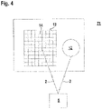
- FIG 4 shows the sensor components of a safety sensor 71 designed as a camera sensor.
- This safety sensor 71 has an illumination unit 12 emitting light beams 2 and an image sensor 13 as a receiver, which can be designed in the form of a CCD or CMOS array with a matrix-like arrangement of receiving elements 14.
- each safety sensor 71 has an evaluation unit, not shown, in which the received signals of the receiver 4 are evaluated.
- the evaluation is carried out in such a way that a protective field monitor 710 ( figure 7 ) is carried out and a binary switching signal 40 is generated depending on an object intervention in a protective field 73, the switching states of which indicate whether an object 5 is present in the protective field 73 or not. If an object 5 is present in the protective field 73, a safety function is triggered by the corresponding switching state of the switching signal 40 in such a way that the hazardous installation 81 is shut down so that no more dangers can emanate from it.
- the optical sensors are Figures 2 to 5 designed as a safety sensor 71 and have a fail-safe design, which could be implemented, for example, by a redundant evaluation unit in the form of two computer units that cyclically monitor one another.
- FIG. 12 shows a safety sensor 71 in the form of a light curtain, by means of which a flat monitoring area is monitored as a protective field 73.
- the light curtain has a transmitter unit 15 and a receiver unit 16, the components of which are each integrated in a housing and which are arranged on opposite edges of the surveillance area.
- a series arrangement of transmitters 3 emitting light beams 2 is located in the transmitter unit 15, and a corresponding number of receivers 4 is located in the receiver unit 16.
- One transmitter 3 and one receiver 4 lying opposite each other form a beam axis.
- the beam axes are activated cyclically one after the other by a transmitter control (not shown) and an optical synchronization.
- Object detection is based on the light barrier principle.
- a threshold value evaluation of the received signals of the receivers 4 is carried out in an evaluation unit in order to generate a binary switching signal 40.
- a switching signal 40 with the switching state "free monitoring area" is generated if the light beams 2 of all beam axes hit the respective receiver 4 unhindered. If at least one beam axis is interrupted by an object intrusion, a switching signal 40 with the switching state "object present” is generated in the evaluation unit.
- the evaluation unit has a redundant structure.
- figure 6 shows the course of time-varying sequences 31, 32 of measurement data from the safety sensor 71 or the image detection sensor 61, which in the present case are formed by images 21 to 25.
- the sequences 31, 32 can also vary spatially or depending on other state variables.
- the newer sequence 31 is the time interval 41 before the switching signal 40 is switched.
- the older sequence 32 is the time interval 42 before the switching signal 40 is switched.
- the switching signal 40 switches from 0 to 1, the safety function is triggered. Because the sequences 31, 32 before this Switching process are present, warning messages and / or corrective actions 641 can be generated based on the sequences 31, 32 before the safety function is triggered. Ideally, this can prevent the safety function from being triggered.
- an observable situation 50 at a plant 81 is shown with the reference number 50 .
- this can be formed by a driving area in front of a vehicle, an access area in front of a machine or a robot.
- the observable situation 50 can be the entire or partial scenery of a machine with a person environment or in the environment of other machines/vehicles.
- the observable situation 50 can be the entire or partial scenery of a robot with a person environment or in the environment of other machines/vehicles.
- the safety sensor 71 carries out protective field monitoring 710. If the safety sensor 71 registers an object intrusion in the protective field 73, it generates a switching signal 40 which triggers a safety function, which in the present case is formed by a switch-off signal 711 for the system 81.
- a switch-off information 712 which contains information about the switch-off signal 711 and possibly further information associated therewith, for example more precise information about the protective field violation, is supplied by the safety sensor 71 to the neural learning system 63 in order to use this information to learn the parameters 631.
- the neural system 60 forms a self-learning system in such a way that the learning neural system 63 generates parameters 631 that are used in the neural system 64 that is used to generate output signals, through which warning messages and/or corrective interventions 641 for the system control 80 are issued Appendix 81 are generated.
- the neural system 60 receives boundary parameters 601 as input variables in the form of influencing variables such as time of day, weather information, specification of the shift for the system 81 and the like.
- the image detection sensor 61 detects a field of view 620 and generates image data 610 which are fed to a pre-processing unit 62 .
- the pre-processed image data 621 generated there are supplied to the learning neural system 63 to define the parameters 631 and to the applying neural system 64 to generate the output signals.
- the learned parameters 631 are fed from the learning neural system 63 to the applying neural system 64 .
- the applying neural system 64 generates an override signal that activates a visual or audible alarm to issue a warning. Furthermore, the influencing signal causes a corrective action 641 in the installation 81.
- the corrective action 641 can be a slowing down of a working movement of the installation 81. Furthermore, the corrective intervention 641 can be the initiation of an evasive maneuver by a vehicle forming the system 81 .
- the protective field is influenced 811 of the safety sensor 71.
- a system influencing signal 812 is fed from the system 81 to the neural system 60, which influences the neural systems 63, 64.
- individual neural networks 100 figure 10 forming the neural systems 63, 64 can be selected and combined.
- the neural system 60 has a modifier 65, by means of which the influencing signals can be modified.
- varying correction interventions 641 in the form of system interventions can thus be generated in order to learn the optimal system intervention from the later behavior.
- figure 8 shows a variant of the embodiment according to FIG figure 7 .
- the safety sensor 71 is not only used for protective field monitoring 710 . Rather, the safety sensor 71 also records measurement data in the form of image data 610 or contour data, which are fed to the neural system 60 as input variables 713 . A separate image detection sensor 61 is not required in this case.
- figure 9 12 shows a specific implementation of the functioning of the neural system 60 according to FIG figure 7 .
- Input variables 713 in particular image data 610 or preprocessed image data 611, 621, are fed to learning neural networks LN1, LN2, LN3 with offsets V1, V2, V3.
- the learned parameters 631 are fed to applying decision trees AN1, AN2, AN3, where the applying decision trees AN1, AN2, AN3 are fed the data with no offset V1, V2, V3 (as shown) or other offsets (not shown).
- other external information or the switch-off information 712 could also be fed into the neural networks 100 . Learning about staggered situations can significantly improve the prediction quality of corrective actions.
- the outputs of the applying neural systems 64 are weighted with a weighting function G(x), for example.
- the type of weighting can optionally be varied by the system controller 80 depending on the situation. In the simplest case, the weighting can only be a simple selection.
- figure 10 shows the structure of a neural network 100 that can be used in the neural system 60.
- the neural system 60 has an algorithm 102 .
- the neural network 100 consists of individual functions that are organized in layers 121-124.
- the individual functions can be filter functions, functional relationships, transfer functions, decision matrices or neural networks.
- Layer 121 is used to receive input values 101.
- Layers 122, 123 are used to map intermediate variables.
- the layer 124 forms an output layer, in which the results of the previous layers 121 to 123 are combined to form an overall result, as a result of which output variables 103 are generated.
- Links 125 link individual layers 121 to 124, expediently with weightings of individual variables.
- FIG. 1 shows a specific embodiment of the neural network 100 according to FIG figure 10 .
- this type of neural network 100 all neurons in a layer 121 to 124 are linked to every neuron in the subsequent layer 122, 123, 124.
- the input signals x n of a neuron are weighted w n and summed up.
- another weight b is added.
- the intermediate result is subjected to a transfer function (activation function) f(z) in order to obtain the output signal y of the neuron.
- activation function activation function
- figure 12 shows a neural decision tree 200 for the neural system 60.
- Input variables in the form of MW are supplied to a binning layer BL via evaluation nodes BK.
- Combinations for example Kronecker product KK
- a weighting layer GL is fed to a weighting layer GL.
- output variables 103 are generated by weighting in a weighting layer GL.
Landscapes
- Engineering & Computer Science (AREA)
- General Engineering & Computer Science (AREA)
- Physics & Mathematics (AREA)
- Theoretical Computer Science (AREA)
- Mechanical Engineering (AREA)
- General Health & Medical Sciences (AREA)
- General Physics & Mathematics (AREA)
- Computational Linguistics (AREA)
- Data Mining & Analysis (AREA)
- Evolutionary Computation (AREA)
- Biomedical Technology (AREA)
- Molecular Biology (AREA)
- Computing Systems (AREA)
- Artificial Intelligence (AREA)
- Biophysics (AREA)
- Mathematical Physics (AREA)
- Software Systems (AREA)
- Life Sciences & Earth Sciences (AREA)
- Health & Medical Sciences (AREA)
- Radar, Positioning & Navigation (AREA)
- Remote Sensing (AREA)
- Emergency Alarm Devices (AREA)
Priority Applications (1)
| Application Number | Priority Date | Filing Date | Title |
|---|---|---|---|
| EP21158487.5A EP4047523A1 (fr) | 2021-02-22 | 2021-02-22 | Dispositif de surveillance et procédé de fonctionnement d'un dispositif de surveillance |
Applications Claiming Priority (1)
| Application Number | Priority Date | Filing Date | Title |
|---|---|---|---|
| EP21158487.5A EP4047523A1 (fr) | 2021-02-22 | 2021-02-22 | Dispositif de surveillance et procédé de fonctionnement d'un dispositif de surveillance |
Publications (1)
| Publication Number | Publication Date |
|---|---|
| EP4047523A1 true EP4047523A1 (fr) | 2022-08-24 |
Family
ID=74673125
Family Applications (1)
| Application Number | Title | Priority Date | Filing Date |
|---|---|---|---|
| EP21158487.5A Pending EP4047523A1 (fr) | 2021-02-22 | 2021-02-22 | Dispositif de surveillance et procédé de fonctionnement d'un dispositif de surveillance |
Country Status (1)
| Country | Link |
|---|---|
| EP (1) | EP4047523A1 (fr) |
Citations (2)
| Publication number | Priority date | Publication date | Assignee | Title |
|---|---|---|---|---|
| DE102017218917A1 (de) * | 2017-10-24 | 2019-04-25 | Robert Bosch Gmbh | Überwachungsvorrichtung, Industrieanlage, Verfahren zur Überwachung sowie Computerprogramm |
| EP3730250A1 (fr) * | 2019-04-24 | 2020-10-28 | Adolf Würth GmbH & Co. KG | Procédé de fermeture d'urgence des outils guidés à la main et outil guidé à la main |
-
2021
- 2021-02-22 EP EP21158487.5A patent/EP4047523A1/fr active Pending
Patent Citations (2)
| Publication number | Priority date | Publication date | Assignee | Title |
|---|---|---|---|---|
| DE102017218917A1 (de) * | 2017-10-24 | 2019-04-25 | Robert Bosch Gmbh | Überwachungsvorrichtung, Industrieanlage, Verfahren zur Überwachung sowie Computerprogramm |
| EP3730250A1 (fr) * | 2019-04-24 | 2020-10-28 | Adolf Würth GmbH & Co. KG | Procédé de fermeture d'urgence des outils guidés à la main et outil guidé à la main |
Similar Documents
| Publication | Publication Date | Title |
|---|---|---|
| EP2083209B1 (fr) | Système de sécurité destiné à la mesure sans contact de voies et/ou de vitesses | |
| EP2558886B1 (fr) | Dispositif de surveillance d'au moins une zone de sécurité tridimensionnelle | |
| EP0675420B1 (fr) | Dispositif de surveillance pour la surveillance de la sécurité des aéronefs | |
| EP1993081B1 (fr) | Dispositif de capteur optoélectronique et procédé de surveillance d'une zone de surveillance | |
| EP2053538B1 (fr) | Protection d'une zone de surveillance et support visuel d'un usinage automatisé | |
| EP1300691A2 (fr) | Procédé de surveillance et capteur opto-électronique | |
| EP1788467A2 (fr) | Dispositif de protection | |
| EP1269762B2 (fr) | Dispositif de securite servant a empecher l'acces a une zone dangereuse et procede pour verifier la securite de fonctionnement d'un tel dispositif | |
| WO2019001796A1 (fr) | Procédé, dispositif et support d'enregistrement pouvant être lu par un ordinateur pourvu d'instructions pour la résolution d'une redondance de deux modules redondants ou plus | |
| EP0952039B1 (fr) | Dispositif pour avertir un conducteur de véhicule lors d'assoupissement | |
| EP3287809B1 (fr) | Procédé de fonctionnement d'un dispositif de baleyage et dispositif de baleyage | |
| DE102012215465A1 (de) | Verfahren und Informationssystem zum Filtern von Objektinformationen | |
| DE102018100650A1 (de) | Verfahren zur Kollisionsvermeidung für ein Kraftfahrzeug mit einem Fahrunterstützungssystem | |
| EP4047523A1 (fr) | Dispositif de surveillance et procédé de fonctionnement d'un dispositif de surveillance | |
| DE102017218587A1 (de) | Vorrichtung und Verfahren zur Überwachung eines scannenden Lasersystems sowie eine Laservorrichtung zur Ausführung einer Überwachung eines scannenden Lasersystems | |
| EP3203262B1 (fr) | Dispositif opto-électrique de protection contre une source de danger | |
| EP1146353A2 (fr) | Dispositif détecteur optoélectronique et méthode pour actionner un dispositif détecteur optoélectronique | |
| WO2020038535A1 (fr) | Procédé de détermination de paramètres liés à un accident au moyen d'un système radar d'un véhicule | |
| DE102015225742A1 (de) | Verfahren zum Verarbeiten von Sensorsignalen zum Steuern einer Personenschutzeinrichtung eines Fahrzeugs, Steuergerät und Fahrzeug | |
| DE102019127826B4 (de) | Sicherer optoelektronischer Sensor und Verfahren zum Absichern eines Überwachungsbereichs | |
| DE102021206297A1 (de) | Verfahren und System zum Betreiben eines wenigstens teilweise automatisierten Fahrzeugs | |
| EP2306145A1 (fr) | Capteur optique | |
| DE102015226613A1 (de) | Verfahren zum Optimieren der Umfeldsensierung in einem Fahrzeug | |
| DE102009053395B4 (de) | System und Verfahren zur Überwachung von Zielobjekten | |
| DE102020207990B4 (de) | Verfahren zum Betreiben eines Fahrerassistenzsystems und Fahrerassistenzsystem |
Legal Events
| Date | Code | Title | Description |
|---|---|---|---|
| PUAI | Public reference made under article 153(3) epc to a published international application that has entered the european phase |
Free format text: ORIGINAL CODE: 0009012 |
|
| STAA | Information on the status of an ep patent application or granted ep patent |
Free format text: STATUS: REQUEST FOR EXAMINATION WAS MADE |
|
| 17P | Request for examination filed |
Effective date: 20210929 |
|
| AK | Designated contracting states |
Kind code of ref document: A1 Designated state(s): AL AT BE BG CH CY CZ DE DK EE ES FI FR GB GR HR HU IE IS IT LI LT LU LV MC MK MT NL NO PL PT RO RS SE SI SK SM TR |
|
| STAA | Information on the status of an ep patent application or granted ep patent |
Free format text: STATUS: EXAMINATION IS IN PROGRESS |
|
| 17Q | First examination report despatched |
Effective date: 20240104 |